EP3382151A1 - Composant de turbine comprenant des goupilles de refroidissement moulées - Google Patents
Composant de turbine comprenant des goupilles de refroidissement moulées Download PDFInfo
- Publication number
- EP3382151A1 EP3382151A1 EP18163803.2A EP18163803A EP3382151A1 EP 3382151 A1 EP3382151 A1 EP 3382151A1 EP 18163803 A EP18163803 A EP 18163803A EP 3382151 A1 EP3382151 A1 EP 3382151A1
- Authority
- EP
- European Patent Office
- Prior art keywords
- cooling
- curved surface
- shaped cooling
- turbine
- pins
- Prior art date
- Legal status (The legal status is an assumption and is not a legal conclusion. Google has not performed a legal analysis and makes no representation as to the accuracy of the status listed.)
- Granted
Links
- 238000001816 cooling Methods 0.000 title claims abstract description 199
- 239000012809 cooling fluid Substances 0.000 claims abstract description 41
- 239000012530 fluid Substances 0.000 claims abstract description 11
- 238000004891 communication Methods 0.000 claims abstract description 9
- 238000011144 upstream manufacturing Methods 0.000 claims abstract description 5
- 239000000428 dust Substances 0.000 description 19
- 239000004576 sand Substances 0.000 description 19
- 238000009825 accumulation Methods 0.000 description 16
- 239000002245 particle Substances 0.000 description 14
- 239000013256 coordination polymer Substances 0.000 description 8
- 239000010419 fine particle Substances 0.000 description 7
- 239000002184 metal Substances 0.000 description 2
- 239000000654 additive Substances 0.000 description 1
- 230000000996 additive effect Effects 0.000 description 1
- 238000000149 argon plasma sintering Methods 0.000 description 1
- 238000002485 combustion reaction Methods 0.000 description 1
- 239000013078 crystal Substances 0.000 description 1
- 239000000446 fuel Substances 0.000 description 1
- 238000005495 investment casting Methods 0.000 description 1
- 238000004519 manufacturing process Methods 0.000 description 1
- 239000000463 material Substances 0.000 description 1
- 229910001092 metal group alloy Inorganic materials 0.000 description 1
- 230000007704 transition Effects 0.000 description 1
Images


Classifications
-
- F—MECHANICAL ENGINEERING; LIGHTING; HEATING; WEAPONS; BLASTING
- F01—MACHINES OR ENGINES IN GENERAL; ENGINE PLANTS IN GENERAL; STEAM ENGINES
- F01D—NON-POSITIVE DISPLACEMENT MACHINES OR ENGINES, e.g. STEAM TURBINES
- F01D5/00—Blades; Blade-carrying members; Heating, heat-insulating, cooling or antivibration means on the blades or the members
- F01D5/12—Blades
- F01D5/14—Form or construction
- F01D5/18—Hollow blades, i.e. blades with cooling or heating channels or cavities; Heating, heat-insulating or cooling means on blades
- F01D5/187—Convection cooling
-
- F—MECHANICAL ENGINEERING; LIGHTING; HEATING; WEAPONS; BLASTING
- F01—MACHINES OR ENGINES IN GENERAL; ENGINE PLANTS IN GENERAL; STEAM ENGINES
- F01D—NON-POSITIVE DISPLACEMENT MACHINES OR ENGINES, e.g. STEAM TURBINES
- F01D5/00—Blades; Blade-carrying members; Heating, heat-insulating, cooling or antivibration means on the blades or the members
- F01D5/12—Blades
- F01D5/14—Form or construction
- F01D5/18—Hollow blades, i.e. blades with cooling or heating channels or cavities; Heating, heat-insulating or cooling means on blades
-
- F—MECHANICAL ENGINEERING; LIGHTING; HEATING; WEAPONS; BLASTING
- F05—INDEXING SCHEMES RELATING TO ENGINES OR PUMPS IN VARIOUS SUBCLASSES OF CLASSES F01-F04
- F05D—INDEXING SCHEME FOR ASPECTS RELATING TO NON-POSITIVE-DISPLACEMENT MACHINES OR ENGINES, GAS-TURBINES OR JET-PROPULSION PLANTS
- F05D2220/00—Application
- F05D2220/30—Application in turbines
- F05D2220/32—Application in turbines in gas turbines
- F05D2220/323—Application in turbines in gas turbines for aircraft propulsion, e.g. jet engines
-
- F—MECHANICAL ENGINEERING; LIGHTING; HEATING; WEAPONS; BLASTING
- F05—INDEXING SCHEMES RELATING TO ENGINES OR PUMPS IN VARIOUS SUBCLASSES OF CLASSES F01-F04
- F05D—INDEXING SCHEME FOR ASPECTS RELATING TO NON-POSITIVE-DISPLACEMENT MACHINES OR ENGINES, GAS-TURBINES OR JET-PROPULSION PLANTS
- F05D2240/00—Components
- F05D2240/20—Rotors
- F05D2240/30—Characteristics of rotor blades, i.e. of any element transforming dynamic fluid energy to or from rotational energy and being attached to a rotor
-
- F—MECHANICAL ENGINEERING; LIGHTING; HEATING; WEAPONS; BLASTING
- F05—INDEXING SCHEMES RELATING TO ENGINES OR PUMPS IN VARIOUS SUBCLASSES OF CLASSES F01-F04
- F05D—INDEXING SCHEME FOR ASPECTS RELATING TO NON-POSITIVE-DISPLACEMENT MACHINES OR ENGINES, GAS-TURBINES OR JET-PROPULSION PLANTS
- F05D2250/00—Geometry
- F05D2250/10—Two-dimensional
- F05D2250/18—Two-dimensional patterned
-
- F—MECHANICAL ENGINEERING; LIGHTING; HEATING; WEAPONS; BLASTING
- F05—INDEXING SCHEMES RELATING TO ENGINES OR PUMPS IN VARIOUS SUBCLASSES OF CLASSES F01-F04
- F05D—INDEXING SCHEME FOR ASPECTS RELATING TO NON-POSITIVE-DISPLACEMENT MACHINES OR ENGINES, GAS-TURBINES OR JET-PROPULSION PLANTS
- F05D2250/00—Geometry
- F05D2250/60—Structure; Surface texture
-
- F—MECHANICAL ENGINEERING; LIGHTING; HEATING; WEAPONS; BLASTING
- F05—INDEXING SCHEMES RELATING TO ENGINES OR PUMPS IN VARIOUS SUBCLASSES OF CLASSES F01-F04
- F05D—INDEXING SCHEME FOR ASPECTS RELATING TO NON-POSITIVE-DISPLACEMENT MACHINES OR ENGINES, GAS-TURBINES OR JET-PROPULSION PLANTS
- F05D2260/00—Function
- F05D2260/20—Heat transfer, e.g. cooling
- F05D2260/221—Improvement of heat transfer
- F05D2260/2212—Improvement of heat transfer by creating turbulence
-
- F—MECHANICAL ENGINEERING; LIGHTING; HEATING; WEAPONS; BLASTING
- F05—INDEXING SCHEMES RELATING TO ENGINES OR PUMPS IN VARIOUS SUBCLASSES OF CLASSES F01-F04
- F05D—INDEXING SCHEME FOR ASPECTS RELATING TO NON-POSITIVE-DISPLACEMENT MACHINES OR ENGINES, GAS-TURBINES OR JET-PROPULSION PLANTS
- F05D2260/00—Function
- F05D2260/20—Heat transfer, e.g. cooling
- F05D2260/221—Improvement of heat transfer
- F05D2260/2214—Improvement of heat transfer by increasing the heat transfer surface
- F05D2260/22141—Improvement of heat transfer by increasing the heat transfer surface using fins or ribs
-
- F—MECHANICAL ENGINEERING; LIGHTING; HEATING; WEAPONS; BLASTING
- F05—INDEXING SCHEMES RELATING TO ENGINES OR PUMPS IN VARIOUS SUBCLASSES OF CLASSES F01-F04
- F05D—INDEXING SCHEME FOR ASPECTS RELATING TO NON-POSITIVE-DISPLACEMENT MACHINES OR ENGINES, GAS-TURBINES OR JET-PROPULSION PLANTS
- F05D2260/00—Function
- F05D2260/60—Fluid transfer
- F05D2260/607—Preventing clogging or obstruction of flow paths by dirt, dust, or foreign particles
-
- Y—GENERAL TAGGING OF NEW TECHNOLOGICAL DEVELOPMENTS; GENERAL TAGGING OF CROSS-SECTIONAL TECHNOLOGIES SPANNING OVER SEVERAL SECTIONS OF THE IPC; TECHNICAL SUBJECTS COVERED BY FORMER USPC CROSS-REFERENCE ART COLLECTIONS [XRACs] AND DIGESTS
- Y02—TECHNOLOGIES OR APPLICATIONS FOR MITIGATION OR ADAPTATION AGAINST CLIMATE CHANGE
- Y02T—CLIMATE CHANGE MITIGATION TECHNOLOGIES RELATED TO TRANSPORTATION
- Y02T50/00—Aeronautics or air transport
- Y02T50/60—Efficient propulsion technologies, e.g. for aircraft
Definitions
- the present disclosure generally relates to gas turbine engines, and more particularly relates to a turbine component, such as a turbine airfoil, for use within a gas turbine engine that has one or more shaped cooling pins.
- Gas turbine engines may be employed to power various devices.
- a gas turbine engine may be employed to power a mobile platform, such as an aircraft, rotorcraft, etc.
- certain operating environments such as desert operating environments, may cause the gas turbine engine to ingest fine sand and dust particles. These ingested fine sand and dust particles may pass through portions of the gas turbine engine and may accumulate in stagnation regions of cooling circuits within turbine components, such as turbine airfoils, associated with the gas turbine engine.
- the accumulation of the fine sand and dust particles in the stagnation regions of the cooling circuits in the turbine components, such as the turbine airfoil, may impede the cooling of the turbine airfoil, which in turn, may reduce the life of the turbine airfoil leading to increased repair costs and downtime for the gas turbine engine.
- a turbine component such as a turbine airfoil
- one or more shaped cooling pins which enable the cooling of the turbine component, such as a turbine airfoil, while reducing a stagnation region within the cooling circuit.
- the turbine airfoil having the one or more shaped cooling pins which reduce the accumulation of fine sand and dust particles, thereby maintaining the cooling of the turbine airfoil in operating environments having fine sand and dust particles.
- a turbine component in various embodiments, includes at least one cooling circuit defined within the turbine component, the at least one cooling circuit in fluid communication with a source of a cooling fluid.
- the turbine component includes at least one shaped cooling pin disposed in the at least one cooling circuit.
- the at least one shaped cooling pin has a first end and a second end extending along an axis.
- the first end has a first curved surface defined by a minor diameter and the second end has a second curved surface defined by a major diameter.
- the first curved surface is upstream in the cooling fluid and the minor diameter is less than the major diameter.
- the turbine component includes at least one cooling circuit defined within the turbine component.
- the at least one cooling circuit is in fluid communication with a source of a cooling fluid.
- the turbine component includes a plurality of shaped cooling pins disposed in the at least one cooling circuit in a pattern that includes at least one row of a first sub-plurality of the plurality of shaped cooling pins and at least one column of a second sub-plurality of the plurality of shaped cooling pins.
- Each of the at least one row of the shaped cooling pins is spaced apart by a first distance
- each of the at least one column of the shaped cooling pins is spaced apart by a second distance. The first distance is different than the second distance.
- Each of the plurality of shaped cooling pins has a first end and a second end extending along an axis.
- the first end has a first curved surface defined by a minor diameter and the second end has a second curved surface defined by a major diameter.
- the second curved surface is downstream from the first curved surface in the cooling fluid and the minor diameter is less than the major diameter.
- turbine airfoil is described herein as being used with an axial turbine of a gas turbine engine onboard a mobile platform or vehicle, such as a bus, motorcycle, train, motor vehicle, marine vessel, aircraft, rotorcraft and the like
- the various teachings of the present disclosure can be used with a gas turbine engine or with an axial or radial turbine associated with a stationary platform.
- the present disclosure may be employed in airfoils or other components for use within other applications that require cooling.
- many alternative or additional functional relationships or physical connections may be present in an embodiment of the present disclosure.
- the figures shown herein depict an example with certain arrangements of elements, additional intervening elements, devices, features, or components may be present in an actual embodiment. It should also be understood that the drawings are merely illustrative and may not be drawn to scale.
- FIG. 1 a partial, cross-sectional view of an exemplary gas turbine engine 100 is shown with the remaining portion of the gas turbine engine 100 being axi-symmetric about a longitudinal axis 140, which also comprises an axis of rotation for the gas turbine engine 100.
- the gas turbine engine 100 is an annular multi-spool turbofan gas turbine jet engine 100 within an aircraft 99, although other arrangements and uses may be provided.
- the gas turbine engine 100 may be an auxiliary power unit ("APU").
- APU auxiliary power unit
- an airfoil of one or more turbine blades 200 associated with the gas turbine engine 100 includes one or more shaped cooling pins within an internal cooling circuit, which aid in cooling the airfoil.
- a stagnation region is reduced within the internal cooling circuit, thereby reducing an accumulation of fine sand and dust particles.
- the cooling of the turbine airfoil of the turbine blade is maintained, even in operating environments that include fine sand and dust particles.
- the gas turbine engine 100 includes a fan section 102, a compressor section 104, a combustor section 106, a turbine section 108 and an exhaust section 110.
- the fan section 102 includes a fan 112 mounted on a rotor 114 that draws air into the gas turbine engine 100 and accelerates it. A fraction of the accelerated air exhausted from the fan 112 is directed through an outer (or first) bypass duct 116 and the remaining fraction of air exhausted from the fan 112 is directed into the compressor section 104.
- the outer bypass duct 116 is generally defined by an inner casing 118 and an outer casing 144.
- the compressor section 104 includes a low pressure compressor 120 and a high pressure compressor 122.
- the number of compressors in the compressor section 104 may vary.
- the low pressure compressor 120 and the high pressure compressor 122 sequentially raise the pressure of the air and direct a majority of the high pressure air into the combustor section 106.
- a fraction of the compressed air bypasses the combustor section 106 and is used as a source of cooling fluid or air to cool other components, in this example, the turbine airfoil of the one or more turbine blades 200 in the turbine section 108.
- the high pressure air is mixed with fuel and combusted.
- the high-temperature combusted air is then directed into the turbine section 108.
- the turbine section 108 includes three turbines disposed in axial flow series, namely, a high pressure turbine 126, a low pressure turbine 128, and a power turbine 130.
- the number of turbines, and/or the configurations thereof may vary.
- the high-temperature combusted air from the combustor section 106 expands through and rotates each turbine 126, 128, and 130.
- each drives equipment in the gas turbine engine 100 via concentrically disposed shafts or spools.
- the high pressure turbine 126 drives the high pressure compressor 122 via a shaft 134
- the low pressure turbine 128 drives the low pressure compressor 120 via a shaft 136
- the power turbine 130 drives the fan 112 via a shaft 138.
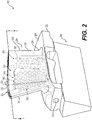
- the turbine blade 200 for use with one or more of the turbines 126, 128, and 130 of the gas turbine engine 100 is shown.
- the turbine blade 200 is associated with the high pressure turbine 126; however, the turbine blade 200 may be associated with the low pressure turbine 128 or the power turbine 130.
- the turbine blade 200 includes a shank 202, an airfoil 204, a platform 206 and a root 208.
- the shank 202 defines a cooling fluid inlet 210.
- the cooling fluid inlet 210 is in fluid communication with a source of a cooling fluid F, which in this example is a fraction of the compressed air that bypasses the combustor section 106 ( FIG. 1 ).
- cooling fluid F is described herein as comprising compressed air, any suitable source of cooling fluid may be employed.
- the cooling fluid F received by the cooling fluid inlet 210 internally cools the turbine blade 200.
- the cooling fluid inlet 210 directs the cooling fluid into a manifold 212.
- the manifold 212 is defined within the shank 202 and a portion of the root 208.
- the manifold 212 is fluidly coupled to the cooling fluid inlet 210 and the airfoil 204 to direct the cooling fluid F into the airfoil 204.
- shape of the manifold 212 is merely exemplary.
- the platform 206 is configured to radially contain turbine airflow.
- the root 208 provides an area in which a fir-tree may be machined (not shown).
- the fir-tree is used to attach the turbine blade 200 to a turbine rotor disc (not shown). It should be understood, however, that the shape of the root 208 is merely exemplary.
- the airfoil 204 has a first, concave outer wall 220 and a second, convex outer wall 222, each having outer surfaces that together define an airfoil shape.
- the airfoil 204 includes a leading edge 224, a trailing edge 226, a pressure side 228 along the first outer wall 220, a suction side 230 along the second outer wall 222, a blade tip 232 and an airfoil platform fillet 234.
- the airfoil 204 is coupled to the platform 206, and the airfoil platform fillet 234 surrounds the intersection between the airfoil 204 and the platform 206 to transition between the airfoil 204 and the platform 206.
- an internal cooling circuit 240 is defined within an interior cavity 236 defined in the airfoil 204 between the first outer wall 220 and the second outer wall 222.
- the internal cooling circuit 240 includes a first cooling circuit 242, a second cooling circuit 244 and a third cooling circuit 246.
- the first cooling circuit 242 is defined along the leading edge 224, and extends from a first inlet 248 adjacent to and in fluid communication with the manifold 212 to a first tip ejector 250 at the blade tip 232.
- the first cooling circuit 242 directs a portion of the cooling fluid F from the manifold 212 along the leading edge 224 to cool the leading edge 224.
- the second cooling circuit 244 is defined between the first cooling circuit 242 and the third cooling circuit 246.
- the second cooling circuit 244 extends from a second inlet 252 and a third inlet 254 each adjacent to and in fluid communication with the manifold 212 to a second tip ejector 256 at the blade tip 232.
- the second cooling circuit 244 directs a portion of the cooling fluid F from the manifold 212 between the first outer wall 220 and the second outer wall 222 to cool the pressure side 228 and the suction side 230, respectively.
- the second tip ejector 256 extends from the second cooling circuit 244 at the blade tip 232 near the first tip ejector 250 and does not span a full length of the second cooling circuit 244. It will be understood, however, that the second tip ejector 256 may extend over the full length of the second cooling circuit 244, if desired.
- the third cooling circuit 246 directs a portion of the cooling fluid F along the trailing edge 226 to cool the trailing edge 226.
- the third cooling circuit 246 extends from a fourth inlet 257 adjacent to and in fluid communication with the manifold 212 to a third tip ejector 258.
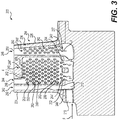
- One or more of the first cooling circuit 242, the second cooling circuit 244 and the third cooling circuit 246 includes a cooling pin bank 260 or an array of shaped cooling pins 262.
- the second cooling circuit 244 and the third cooling circuit 246 each include the cooling pin bank 260.
- the cooling pin bank 260 is defined within the respective one of the second cooling circuit 244 and the third cooling circuit 246 from an area adjacent to the manifold 212 to an area adjacent to the respective one of the second tip ejector 256 and the third tip ejector 258.
- the cooling pin bank 260 of each of the second cooling circuit 244 and the third cooling circuit 246 extends from a respective first end 244', 246' to a respective second end 244", 246" of the second cooling circuit 244 and the third cooling circuit 246, respectively.
- the cooling pin bank 260 enables heat transfer from the first outer wall 220 and the second outer wall 222 into the cooling fluid F that flows through the respective one of the second cooling circuit 244 and the third cooling circuit 246.
- the cooling pin bank 260 includes the plurality of shaped cooling pins 262. Each of the shaped cooling pins 262 are spaced apart and extend between the first outer wall 220 and the second outer wall 222 within the interior cavity 236 defined by the airfoil shape to enable heat transfer from the first outer wall 220 and the second outer wall 222 into the cooling fluid F. As will be discussed, the plurality of shaped cooling pins 262 are generally arranged in an array or pattern in each of the second cooling circuit 244 and the third cooling circuit 246 that defines the cooling pin bank 260.
- the cooling pin bank 260 includes the plurality of shaped cooling pins 262 arranged in rows, generally identified by reference numeral 264, and columns, generally identified by reference numeral 266, to form a pattern 268.
- the pattern includes at least one row of a first sub-plurality of the plurality of shaped cooling pins 262 and at least one column of a second sub-plurality of the plurality of shaped cooling pins 262.
- the pattern 268 includes four rows 264 and three columns 266.
- the plurality of shaped cooling pins 262 are spaced apart from each other in each row 264 in an X-direction by a first distance X 1 .
- the first distance X 1 is measured from a first center point CP 1 of a major diameter D 1 of each adjacent shaped cooling pin 262.
- the first distance X 1 is about (1.0 x D 1 ) to about (6.0 x D 1 ).
- adjacent ones of the first sub-plurality of shaped cooling pins 262 in the respective row 264 are spaced apart by the first distance X 1 that is defined between the first center point CP 1 of each of the adjacent ones of the first sub-plurality of shaped cooling pins 262.
- the plurality of shaped cooling pins 262 are described herein as forming a pattern, the plurality of shaped cooling pins 262 need not form a pattern, but rather may be positioned within the cooling circuit as desired to meet predefined cooling requirements for the turbine blade 200.
- the rows 264 of the first plurality of shaped cooling pins 262 are spaced apart from each other in a Y-direction by a second distance Y 2 .
- the second distance Y 2 is measured from a first center point CP 1 of a major diameter D 1 of each adjacent shaped cooling pin 262.
- the second distance Y 2 is about (0.87 x D 1 ) to about (8.0 x D 1 ).
- each shaped cooling pin 262 in the columns 266 of the first sub-plurality of the plurality of shaped cooling pins 262 is spaced apart by the first distance X 1 and each shaped cooling pin 262 in the rows 264 of the second sub-plurality of the plurality of shaped cooling pins 262 is spaced apart by the second distance Y 2 , the first distance X 1 different than the second distance Y 2 .
- the second distance Y 2 is less than the first distance X 1 . In other embodiments, however, the second distance Y 2 may be equal to the first distance X 1 .
- the second plurality of shaped cooling pins 262 in the columns 266 are spaced apart from each other or staggered in the X-direction by a third distance X 3 .
- the third distance X 3 is measured from the first center point CP 1 of the major diameter D 1 of each adjacent shaped cooling pin 262.
- third distance X 3 is less than the first distance X 1 .
- the third distance X 3 is X 1 2 .
- each shaped cooling pin 262 in the columns 266 of the second sub-plurality of the plurality of shaped cooling pins 262 is also spaced apart by the third distance X 3 , the third distance X 3 different than the second distance Y 2 and the first distance X 1 .
- each of the plurality of shaped cooling pins 262 in the cooling pin bank 260 are the same, and thus, only one of the plurality of shaped cooling pins 262 will be described in detail herein.
- the shaped cooling pin 262 has a first end 280 and a second end 282 that extend along an axis A.
- the first end 280 is upstream from the second end 282 in the cooling fluid F.
- the first end 280 faces the manifold 212 ( FIG. 3 ) so as to be positioned upstream in the cooling fluid F.
- the first end 280 has a first curved surface 284 defined by the minor diameter D 2
- the second end 282 has a second curved surface 286 defined by the major diameter D 1 .
- the minor diameter D 2 is smaller than the major diameter D 1 .
- the minor diameter D 2 is about 0.010 inches (in.) to about 0.050 inches (in.); and the major diameter D 1 is about 0.020 inches (in.) to about 0.100 inches (in.).
- the center of minor diameter D 2 is spaced apart from the center of major diameter D 1 by a length L. In one example, the length L is about 0.010 inches (in.) to about 0.150 inches (in.).
- the first curved surface 284 and the second curved surface 286 are interconnected by a pair of surfaces 287 that are defined by a pair of planes that are substantially tangent to a respective one of the first curved surface 284 and the second curved surface 286.
- first curved surface 284 and the second curved surface 286 need not be interconnected by a pair of planes that are substantially tangent to a respective one of the first curved surface 284 and the second curved surface 286. Rather, the first curved surface 284 and the second curved surface 286 may be interconnected by a pair of concave, convex, other shaped surfaces.
- the shape of the shaped cooling pin 262 is defined in cross-section by a first circle 288, a second circle 290 and a pair of tangent lines 292, 294.
- the first circle 288 defines the first curved surface 284 at the first end 280 and has the minor diameter D 2 .
- the second circle 290 defines the second curved surface 286 at the second end 282 and has the major diameter D 1 .
- the first circle 288 includes the second center point CP 2
- the second circle 290 includes the first center point CP 1 .
- the first center point CP 1 is spaced apart from the second center point CP 2 by the length L.
- the length L is greater than zero.
- the first curved surface 284 is spaced apart from the second curved surface 286 by the length L.
- the tangent lines 292, 294 interconnect the first curved surface 284 and the second curved surface 286.
- the tangent line 292 touches the first curved surface 284 and the second curved surface 286 on a first side 296 of the shaped cooling pin 262.
- the tangent line 294 touches the first curved surface 284 and the second curved surface 286 on a second side 298 of the shaped cooling pin 262.
- the turbine blade 200 having the cooling pin bank 260 including the plurality of shaped cooling pins 262 may be cast as one-piece, from a suitable metal or metal alloy, such as MAR-M 247 equiaxed or directionally solidified, or from a single crystal material.
- the turbine blade 200 is formed using investment casting, and the fir-tree 209 is machined in a subsequent processing step.
- the turbine blade 200 may be formed using conventional dies with one or more portions of a core (or portions adjacent to the core) comprising a fugitive core insert.
- turbine blade 200 may be formed through additive manufacturing methods such as direct metal laser sintering.
- the fir-tree ( FIG. 2 ) may be machined into the root 208. With the fir-tree machined into the root 208, the turbine blade 200 may be coupled to a turbine rotor disc. Generally, a plurality of the turbine blades 200 is assembled into the turbine rotor disc to form the high pressure turbine 126. With the high pressure turbine 126 assembled, the high pressure turbine 126 is coupled to or integral with the gas turbine engine 100.
- the fine sand and dust may be ingested by the gas turbine engine 100, via the fan section 102, for example.
- any of the fine sand and dust that is entrained in the cooling fluid F may flow into the internal cooling circuit 240 of the airfoil 204. Due to the shape of the plurality of shaped cooling pins 262, the accumulation of the fine sand and dust particles within the cooling pin bank 260 of the internal cooling circuit 240 is reduced.
- the first curved surface 284 defines a stagnation region of the respective shaped cooling pin 262.
- any accumulation of the fine sand and dust particles is substantially along the stagnation region defined by first curved surface 284.
- the first curved surface 284 has the minor diameter D 2 , which is less than the major diameter D 1 , the stagnation region is reduced, and thus, the accumulation of the fine sand and dust particles is reduced as compared to a cylindrical cooling pin.
- the first curved surface 284 of the shaped cooling pin 262 reduces a stagnation region of the cooling pin, thereby reducing an available surface area for the accumulation of fine sand and dust particles.
- any accumulation of the fine sand and dust particles on the first curved surface 284 results in about a 5 percent (%) reduction in heat transfer area, as compared to about a 50 percent (%) reduction in heat transfer area when a cylindrical cooling pin is employed.
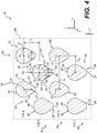
- the cooling pin bank 260 with the plurality of shaped cooling pins 262 is shown schematically in FIG. 5 .
- the cooling effectiveness of the cooling pin bank 260 may be defined by two equations.
- ⁇ F is the effectiveness of the cooling fluid F as the cooling fluid F flows through the cooling pin bank 260;
- T exit is the exit temperature of the cooling fluid F in degrees Kelvin (K);
- T inlet is the inlet temperature of the cooling fluid F in degrees Kelvin (K);
- T hot is the temperature of the working fluid in degrees Kelvin (K). It should be noted that the use of Kelvin (K) as the unit for the temperatures is merely exemplary.
- ⁇ M is the effectiveness of the cooling fluid F in cooling the first outer wall 220 or the second outer wall 222 as the cooling fluid F flows through the cooling pin bank 260;
- T hot is the temperature of the working fluid in degrees Kelvin (K);
- T wall is the temperature of the first outer wall 220 or the second outer wall 222 in degrees Kelvin (K);
- T inlet is the inlet temperature of the cooling fluid F in degrees Kelvin (K).
- Kelvin (K) as the unit for the temperatures is merely exemplary.
- FIGS. 5A a cross-section of a "dirty" one of the plurality of shaped cooling pins 262 is shown, and a cross-section of a "dirty" cylindrical cooling pin 302 is shown in FIG. 5B .
- an accumulation of fine particles 304 is formed on a stagnation region 306 of each of the pins 262, 302.
- a perimeter 308 covered by the accumulation of fine particles 304 on the cylindrical pin 302 is different than, and greater than, a perimeter 310 covered by the accumulation of fine particles 304 on the one of the plurality of shaped cooling pins 262.
- a remaining "clean" perimeter 312 of the cylindrical cooling pin 302 is different, and less than, a remaining "clean” perimeter 314 of the one of the plurality of shaped cooling pins 262.
- the plurality of shaped cooling pins 262 even when "dirty" has a clean surface area that is different from, and greater than, a clean surface area of the cylindrical cooling pin 302.
- the larger clean surface area of each of the plurality of shaped cooling pins 262 enables each of the plurality of shaped cooling pins 262 to be more effective in the transfer of heat from the first outer wall 220 or the second outer wall 222 to the cooling fluid F than the cylindrical cooling pin 302.
- a comparison of the heat transfer performance may be made that illustrates how the effectiveness may decrease as the pins 262, 302 accumulate the fine particles and become "dirty.”
- a cooling pin bank of the plurality of cylindrical pins 302 and the cooling pin bank 260 of the plurality of shaped pins 262 may be defined in a similar manner using the same basic size and spacing between rows and columns, cross sectional channel flow area, cooling flow F (rate and temperature), wall thickness, and the same external convection conditions.
- the plurality of cylindrical cooling pins 302 decrease in effectiveness ⁇ F by about 6.5 percent (%), when the plurality of cylindrical cooling pins 302 are clean and become "dirty;” and decrease in effectiveness ⁇ M by about 5.3 percent (%), when the plurality of cylindrical cooling pins 302 are clean and become “dirty.”
- the plurality of shaped cooling pins 262 decrease in effectiveness ⁇ F by about 0.4 percent (%), when the plurality of shaped cooling pins 262 are clean and become "dirty;” and decrease in effectiveness ⁇ M by about 0.5 percent (%), when the plurality of shaped cooling pins 262 are clean and become "dirty.”
- the "dirty” plurality of shaped cooling pins 262 are about 2.5 percent (%) more effective than “dirty” the plurality of cylindrical cooling pins 302.
- the "dirty" plurality of shaped cooling pins 262 are about 3.7 percent (%) more effective than the "dirty" plurality of shaped cooling pins 262.
- the plurality of shaped cooling pins 262 maintain the cooling of the airfoil 204 even during operating environments in which fine sand and dust may accumulate on the stagnation region of one or more of the plurality of shaped cooling pins 262.
- the first curved surface 284 has the minor diameter D 2 , which is less than the major diameter D 1 , the stagnation region of each of the plurality of shaped cooling pins 262 is reduced, thereby reducing the accumulation of the fine sand and dust particles, which in turn, maintains the cooling of the airfoil 204 in these operating environments.
- the various teachings of the present disclosure provide a turbine component, such as the airfoil 204, which includes the plurality of shaped cooling pins 262.
Landscapes
- Engineering & Computer Science (AREA)
- Mechanical Engineering (AREA)
- General Engineering & Computer Science (AREA)
- Turbine Rotor Nozzle Sealing (AREA)
Applications Claiming Priority (1)
| Application Number | Priority Date | Filing Date | Title |
|---|---|---|---|
| US15/475,597 US10563520B2 (en) | 2017-03-31 | 2017-03-31 | Turbine component with shaped cooling pins |
Publications (2)
| Publication Number | Publication Date |
|---|---|
| EP3382151A1 true EP3382151A1 (fr) | 2018-10-03 |
| EP3382151B1 EP3382151B1 (fr) | 2019-08-07 |
Family
ID=61768148
Family Applications (1)
| Application Number | Title | Priority Date | Filing Date |
|---|---|---|---|
| EP18163803.2A Active EP3382151B1 (fr) | 2017-03-31 | 2018-03-23 | Composant de turbine comprenant des goupilles de refroidissement moulées |
Country Status (2)
| Country | Link |
|---|---|
| US (2) | US10563520B2 (fr) |
| EP (1) | EP3382151B1 (fr) |
Cited By (2)
| Publication number | Priority date | Publication date | Assignee | Title |
|---|---|---|---|---|
| EP3663523A1 (fr) * | 2018-12-05 | 2020-06-10 | United Technologies Corporation | Circuit de refroidissement pour composant de moteur à turbine à gaz |
| EP3819469A1 (fr) * | 2019-11-05 | 2021-05-12 | Honeywell International Inc. | Composant de turbine avec système de refroidissement tolérant à la poussière |
Families Citing this family (2)
| Publication number | Priority date | Publication date | Assignee | Title |
|---|---|---|---|---|
| US10787932B2 (en) | 2018-07-13 | 2020-09-29 | Honeywell International Inc. | Turbine blade with dust tolerant cooling system |
| US10989067B2 (en) | 2018-07-13 | 2021-04-27 | Honeywell International Inc. | Turbine vane with dust tolerant cooling system |
Citations (3)
| Publication number | Priority date | Publication date | Assignee | Title |
|---|---|---|---|---|
| US20120207591A1 (en) * | 2011-02-15 | 2012-08-16 | Ching-Pang Lee | Cooling system having reduced mass pin fins for components in a gas turbine engine |
| US20120269649A1 (en) * | 2011-04-22 | 2012-10-25 | Christopher Rawlings | Turbine blade with improved trailing edge cooling |
| US20140110559A1 (en) * | 2012-10-23 | 2014-04-24 | Ching-Pang Lee | Casting core for a cooling arrangement for a gas turbine component |
Family Cites Families (17)
| Publication number | Priority date | Publication date | Assignee | Title |
|---|---|---|---|---|
| US6599092B1 (en) * | 2002-01-04 | 2003-07-29 | General Electric Company | Methods and apparatus for cooling gas turbine nozzles |
| US7097425B2 (en) * | 2003-08-08 | 2006-08-29 | United Technologies Corporation | Microcircuit cooling for a turbine airfoil |
| US7125225B2 (en) * | 2004-02-04 | 2006-10-24 | United Technologies Corporation | Cooled rotor blade with vibration damping device |
| US7625178B2 (en) | 2006-08-30 | 2009-12-01 | Honeywell International Inc. | High effectiveness cooled turbine blade |
| US20110033311A1 (en) | 2009-08-06 | 2011-02-10 | Martin Nicholas F | Turbine Airfoil Cooling System with Pin Fin Cooling Chambers |
| US8353669B2 (en) * | 2009-08-18 | 2013-01-15 | United Technologies Corporation | Turbine vane platform leading edge cooling holes |
| EP2378073A1 (fr) * | 2010-04-14 | 2011-10-19 | Siemens Aktiengesellschaft | Aube de rotor ou de stator pour turbomachine |
| US8506252B1 (en) | 2010-10-21 | 2013-08-13 | Florida Turbine Technologies, Inc. | Turbine blade with multiple impingement cooling |
| US8807945B2 (en) * | 2011-06-22 | 2014-08-19 | United Technologies Corporation | Cooling system for turbine airfoil including ice-cream-cone-shaped pedestals |
| US8858159B2 (en) | 2011-10-28 | 2014-10-14 | United Technologies Corporation | Gas turbine engine component having wavy cooling channels with pedestals |
| US8926289B2 (en) * | 2012-03-08 | 2015-01-06 | Hamilton Sundstrand Corporation | Blade pocket design |
| US9879546B2 (en) * | 2012-06-21 | 2018-01-30 | United Technologies Corporation | Airfoil cooling circuits |
| WO2014186109A1 (fr) * | 2013-05-15 | 2014-11-20 | United Technologies Corporation | Socle de turbulateur à passage de refroidissement de profil aérodynamique de moteur à turbine à gaz |
| EP2832956A1 (fr) * | 2013-07-29 | 2015-02-04 | Siemens Aktiengesellschaft | Aube de turbine avec corps de refroidissement en forme de profil aérodynamique |
| US20170009589A1 (en) * | 2015-07-09 | 2017-01-12 | Siemens Energy, Inc. | Gas turbine engine blade with increased wall thickness zone in the trailing edge-hub region |
| US10337332B2 (en) * | 2016-02-25 | 2019-07-02 | United Technologies Corporation | Airfoil having pedestals in trailing edge cavity |
| US11333023B2 (en) * | 2018-11-09 | 2022-05-17 | Raytheon Technologies Corporation | Article having cooling passage network with inter-row sub-passages |
-
2017
- 2017-03-31 US US15/475,597 patent/US10563520B2/en active Active
-
2018
- 2018-03-23 EP EP18163803.2A patent/EP3382151B1/fr active Active
-
2019
- 2019-08-20 US US16/546,055 patent/US10954801B2/en active Active
Patent Citations (3)
| Publication number | Priority date | Publication date | Assignee | Title |
|---|---|---|---|---|
| US20120207591A1 (en) * | 2011-02-15 | 2012-08-16 | Ching-Pang Lee | Cooling system having reduced mass pin fins for components in a gas turbine engine |
| US20120269649A1 (en) * | 2011-04-22 | 2012-10-25 | Christopher Rawlings | Turbine blade with improved trailing edge cooling |
| US20140110559A1 (en) * | 2012-10-23 | 2014-04-24 | Ching-Pang Lee | Casting core for a cooling arrangement for a gas turbine component |
Cited By (4)
| Publication number | Priority date | Publication date | Assignee | Title |
|---|---|---|---|---|
| EP3663523A1 (fr) * | 2018-12-05 | 2020-06-10 | United Technologies Corporation | Circuit de refroidissement pour composant de moteur à turbine à gaz |
| US10975710B2 (en) | 2018-12-05 | 2021-04-13 | Raytheon Technologies Corporation | Cooling circuit for gas turbine engine component |
| EP4219903A1 (fr) * | 2018-12-05 | 2023-08-02 | Raytheon Technologies Corporation | Circuit de refroidissement pour composant de moteur à turbine à gaz |
| EP3819469A1 (fr) * | 2019-11-05 | 2021-05-12 | Honeywell International Inc. | Composant de turbine avec système de refroidissement tolérant à la poussière |
Also Published As
| Publication number | Publication date |
|---|---|
| US10563520B2 (en) | 2020-02-18 |
| US20180283182A1 (en) | 2018-10-04 |
| US20200003059A1 (en) | 2020-01-02 |
| EP3382151B1 (fr) | 2019-08-07 |
| US10954801B2 (en) | 2021-03-23 |
Similar Documents
| Publication | Publication Date | Title |
|---|---|---|
| US10954801B2 (en) | Cooling circuit with shaped cooling pins | |
| EP2343435B1 (fr) | Composant de moteur | |
| EP2880276B1 (fr) | Composant de moteur à turbine à gaz et procédé | |
| EP2568119B1 (fr) | Aube de turbine avec agencement de refroidissement du bord de fuite amélioré | |
| US10907648B2 (en) | Airfoil with maximum thickness distribution for robustness | |
| EP3211179B1 (fr) | Aube avec socles dans cavité de bord de fuite | |
| CA2964139A1 (fr) | Profil aerodynamique pour turbine a gaz | |
| EP2662528B1 (fr) | Composant de moteur à turbine à gaz avec des trous de refroidissement ayant une configuration multi-lobée | |
| US11230929B2 (en) | Turbine component with dust tolerant cooling system | |
| US11448093B2 (en) | Turbine vane with dust tolerant cooling system | |
| EP2639405B1 (fr) | Refroidissement d'extrémité d'aube de turbine | |
| EP2848769B1 (fr) | Procédé de production d'une aube rotorique de turbine | |
| US10669862B2 (en) | Airfoil with leading edge convective cooling system | |
| EP3441566B1 (fr) | Profil aérodynamique avec répartition des maximums d'épaisseur pour la robustesse | |
| CA2956346A1 (fr) | Profil dynamique de turbine dote de refroidissement | |
| EP3418494B1 (fr) | Commande de flux secondaire | |
| EP3677750B1 (fr) | Composant de moteur à turbine à gaz avec une fente de décharge sur le bord de fuite |
Legal Events
| Date | Code | Title | Description |
|---|---|---|---|
| PUAI | Public reference made under article 153(3) epc to a published international application that has entered the european phase |
Free format text: ORIGINAL CODE: 0009012 |
|
| STAA | Information on the status of an ep patent application or granted ep patent |
Free format text: STATUS: REQUEST FOR EXAMINATION WAS MADE |
|
| 17P | Request for examination filed |
Effective date: 20180323 |
|
| AK | Designated contracting states |
Kind code of ref document: A1 Designated state(s): AL AT BE BG CH CY CZ DE DK EE ES FI FR GB GR HR HU IE IS IT LI LT LU LV MC MK MT NL NO PL PT RO RS SE SI SK SM TR |
|
| AX | Request for extension of the european patent |
Extension state: BA ME |
|
| RIC1 | Information provided on ipc code assigned before grant |
Ipc: F01D 5/18 20060101AFI20190131BHEP |
|
| GRAP | Despatch of communication of intention to grant a patent |
Free format text: ORIGINAL CODE: EPIDOSNIGR1 |
|
| STAA | Information on the status of an ep patent application or granted ep patent |
Free format text: STATUS: GRANT OF PATENT IS INTENDED |
|
| INTG | Intention to grant announced |
Effective date: 20190320 |
|
| GRAS | Grant fee paid |
Free format text: ORIGINAL CODE: EPIDOSNIGR3 |
|
| GRAA | (expected) grant |
Free format text: ORIGINAL CODE: 0009210 |
|
| STAA | Information on the status of an ep patent application or granted ep patent |
Free format text: STATUS: THE PATENT HAS BEEN GRANTED |
|
| AK | Designated contracting states |
Kind code of ref document: B1 Designated state(s): AL AT BE BG CH CY CZ DE DK EE ES FI FR GB GR HR HU IE IS IT LI LT LU LV MC MK MT NL NO PL PT RO RS SE SI SK SM TR |
|
| REG | Reference to a national code |
Ref country code: GB Ref legal event code: FG4D |
|
| REG | Reference to a national code |
Ref country code: CH Ref legal event code: EP Ref country code: AT Ref legal event code: REF Ref document number: 1164180 Country of ref document: AT Kind code of ref document: T Effective date: 20190815 |
|
| REG | Reference to a national code |
Ref country code: DE Ref legal event code: R096 Ref document number: 602018000364 Country of ref document: DE |
|
| REG | Reference to a national code |
Ref country code: IE Ref legal event code: FG4D |
|
| REG | Reference to a national code |
Ref country code: NL Ref legal event code: MP Effective date: 20190807 |
|
| REG | Reference to a national code |
Ref country code: LT Ref legal event code: MG4D |
|
| PG25 | Lapsed in a contracting state [announced via postgrant information from national office to epo] |
Ref country code: FI Free format text: LAPSE BECAUSE OF FAILURE TO SUBMIT A TRANSLATION OF THE DESCRIPTION OR TO PAY THE FEE WITHIN THE PRESCRIBED TIME-LIMIT Effective date: 20190807 Ref country code: HR Free format text: LAPSE BECAUSE OF FAILURE TO SUBMIT A TRANSLATION OF THE DESCRIPTION OR TO PAY THE FEE WITHIN THE PRESCRIBED TIME-LIMIT Effective date: 20190807 Ref country code: SE Free format text: LAPSE BECAUSE OF FAILURE TO SUBMIT A TRANSLATION OF THE DESCRIPTION OR TO PAY THE FEE WITHIN THE PRESCRIBED TIME-LIMIT Effective date: 20190807 Ref country code: NO Free format text: LAPSE BECAUSE OF FAILURE TO SUBMIT A TRANSLATION OF THE DESCRIPTION OR TO PAY THE FEE WITHIN THE PRESCRIBED TIME-LIMIT Effective date: 20191107 Ref country code: PT Free format text: LAPSE BECAUSE OF FAILURE TO SUBMIT A TRANSLATION OF THE DESCRIPTION OR TO PAY THE FEE WITHIN THE PRESCRIBED TIME-LIMIT Effective date: 20191209 Ref country code: LT Free format text: LAPSE BECAUSE OF FAILURE TO SUBMIT A TRANSLATION OF THE DESCRIPTION OR TO PAY THE FEE WITHIN THE PRESCRIBED TIME-LIMIT Effective date: 20190807 Ref country code: NL Free format text: LAPSE BECAUSE OF FAILURE TO SUBMIT A TRANSLATION OF THE DESCRIPTION OR TO PAY THE FEE WITHIN THE PRESCRIBED TIME-LIMIT Effective date: 20190807 Ref country code: BG Free format text: LAPSE BECAUSE OF FAILURE TO SUBMIT A TRANSLATION OF THE DESCRIPTION OR TO PAY THE FEE WITHIN THE PRESCRIBED TIME-LIMIT Effective date: 20191107 |
|
| REG | Reference to a national code |
Ref country code: AT Ref legal event code: MK05 Ref document number: 1164180 Country of ref document: AT Kind code of ref document: T Effective date: 20190807 |
|
| PG25 | Lapsed in a contracting state [announced via postgrant information from national office to epo] |
Ref country code: ES Free format text: LAPSE BECAUSE OF FAILURE TO SUBMIT A TRANSLATION OF THE DESCRIPTION OR TO PAY THE FEE WITHIN THE PRESCRIBED TIME-LIMIT Effective date: 20190807 Ref country code: LV Free format text: LAPSE BECAUSE OF FAILURE TO SUBMIT A TRANSLATION OF THE DESCRIPTION OR TO PAY THE FEE WITHIN THE PRESCRIBED TIME-LIMIT Effective date: 20190807 Ref country code: AL Free format text: LAPSE BECAUSE OF FAILURE TO SUBMIT A TRANSLATION OF THE DESCRIPTION OR TO PAY THE FEE WITHIN THE PRESCRIBED TIME-LIMIT Effective date: 20190807 Ref country code: IS Free format text: LAPSE BECAUSE OF FAILURE TO SUBMIT A TRANSLATION OF THE DESCRIPTION OR TO PAY THE FEE WITHIN THE PRESCRIBED TIME-LIMIT Effective date: 20191207 Ref country code: RS Free format text: LAPSE BECAUSE OF FAILURE TO SUBMIT A TRANSLATION OF THE DESCRIPTION OR TO PAY THE FEE WITHIN THE PRESCRIBED TIME-LIMIT Effective date: 20190807 Ref country code: GR Free format text: LAPSE BECAUSE OF FAILURE TO SUBMIT A TRANSLATION OF THE DESCRIPTION OR TO PAY THE FEE WITHIN THE PRESCRIBED TIME-LIMIT Effective date: 20191108 |
|
| PG25 | Lapsed in a contracting state [announced via postgrant information from national office to epo] |
Ref country code: TR Free format text: LAPSE BECAUSE OF FAILURE TO SUBMIT A TRANSLATION OF THE DESCRIPTION OR TO PAY THE FEE WITHIN THE PRESCRIBED TIME-LIMIT Effective date: 20190807 |
|
| PG25 | Lapsed in a contracting state [announced via postgrant information from national office to epo] |
Ref country code: PL Free format text: LAPSE BECAUSE OF FAILURE TO SUBMIT A TRANSLATION OF THE DESCRIPTION OR TO PAY THE FEE WITHIN THE PRESCRIBED TIME-LIMIT Effective date: 20190807 Ref country code: EE Free format text: LAPSE BECAUSE OF FAILURE TO SUBMIT A TRANSLATION OF THE DESCRIPTION OR TO PAY THE FEE WITHIN THE PRESCRIBED TIME-LIMIT Effective date: 20190807 Ref country code: AT Free format text: LAPSE BECAUSE OF FAILURE TO SUBMIT A TRANSLATION OF THE DESCRIPTION OR TO PAY THE FEE WITHIN THE PRESCRIBED TIME-LIMIT Effective date: 20190807 Ref country code: RO Free format text: LAPSE BECAUSE OF FAILURE TO SUBMIT A TRANSLATION OF THE DESCRIPTION OR TO PAY THE FEE WITHIN THE PRESCRIBED TIME-LIMIT Effective date: 20190807 Ref country code: IT Free format text: LAPSE BECAUSE OF FAILURE TO SUBMIT A TRANSLATION OF THE DESCRIPTION OR TO PAY THE FEE WITHIN THE PRESCRIBED TIME-LIMIT Effective date: 20190807 Ref country code: DK Free format text: LAPSE BECAUSE OF FAILURE TO SUBMIT A TRANSLATION OF THE DESCRIPTION OR TO PAY THE FEE WITHIN THE PRESCRIBED TIME-LIMIT Effective date: 20190807 |
|
| PG25 | Lapsed in a contracting state [announced via postgrant information from national office to epo] |
Ref country code: IS Free format text: LAPSE BECAUSE OF FAILURE TO SUBMIT A TRANSLATION OF THE DESCRIPTION OR TO PAY THE FEE WITHIN THE PRESCRIBED TIME-LIMIT Effective date: 20200224 Ref country code: SK Free format text: LAPSE BECAUSE OF FAILURE TO SUBMIT A TRANSLATION OF THE DESCRIPTION OR TO PAY THE FEE WITHIN THE PRESCRIBED TIME-LIMIT Effective date: 20190807 Ref country code: CZ Free format text: LAPSE BECAUSE OF FAILURE TO SUBMIT A TRANSLATION OF THE DESCRIPTION OR TO PAY THE FEE WITHIN THE PRESCRIBED TIME-LIMIT Effective date: 20190807 Ref country code: SM Free format text: LAPSE BECAUSE OF FAILURE TO SUBMIT A TRANSLATION OF THE DESCRIPTION OR TO PAY THE FEE WITHIN THE PRESCRIBED TIME-LIMIT Effective date: 20190807 |
|
| REG | Reference to a national code |
Ref country code: DE Ref legal event code: R097 Ref document number: 602018000364 Country of ref document: DE |
|
| PLBE | No opposition filed within time limit |
Free format text: ORIGINAL CODE: 0009261 |
|
| STAA | Information on the status of an ep patent application or granted ep patent |
Free format text: STATUS: NO OPPOSITION FILED WITHIN TIME LIMIT |
|
| PG2D | Information on lapse in contracting state deleted |
Ref country code: IS |
|
| 26N | No opposition filed |
Effective date: 20200603 |
|
| PG25 | Lapsed in a contracting state [announced via postgrant information from national office to epo] |
Ref country code: SI Free format text: LAPSE BECAUSE OF FAILURE TO SUBMIT A TRANSLATION OF THE DESCRIPTION OR TO PAY THE FEE WITHIN THE PRESCRIBED TIME-LIMIT Effective date: 20190807 |
|
| PG25 | Lapsed in a contracting state [announced via postgrant information from national office to epo] |
Ref country code: MC Free format text: LAPSE BECAUSE OF FAILURE TO SUBMIT A TRANSLATION OF THE DESCRIPTION OR TO PAY THE FEE WITHIN THE PRESCRIBED TIME-LIMIT Effective date: 20190807 |
|
| REG | Reference to a national code |
Ref country code: BE Ref legal event code: MM Effective date: 20200331 |
|
| PG25 | Lapsed in a contracting state [announced via postgrant information from national office to epo] |
Ref country code: LU Free format text: LAPSE BECAUSE OF NON-PAYMENT OF DUE FEES Effective date: 20200323 |
|
| PG25 | Lapsed in a contracting state [announced via postgrant information from national office to epo] |
Ref country code: IE Free format text: LAPSE BECAUSE OF NON-PAYMENT OF DUE FEES Effective date: 20200323 Ref country code: FR Free format text: LAPSE BECAUSE OF NON-PAYMENT OF DUE FEES Effective date: 20200331 |
|
| PG25 | Lapsed in a contracting state [announced via postgrant information from national office to epo] |
Ref country code: BE Free format text: LAPSE BECAUSE OF NON-PAYMENT OF DUE FEES Effective date: 20200331 |
|
| REG | Reference to a national code |
Ref country code: CH Ref legal event code: PL |
|
| PG25 | Lapsed in a contracting state [announced via postgrant information from national office to epo] |
Ref country code: LI Free format text: LAPSE BECAUSE OF NON-PAYMENT OF DUE FEES Effective date: 20210331 Ref country code: CH Free format text: LAPSE BECAUSE OF NON-PAYMENT OF DUE FEES Effective date: 20210331 |
|
| PG25 | Lapsed in a contracting state [announced via postgrant information from national office to epo] |
Ref country code: MT Free format text: LAPSE BECAUSE OF FAILURE TO SUBMIT A TRANSLATION OF THE DESCRIPTION OR TO PAY THE FEE WITHIN THE PRESCRIBED TIME-LIMIT Effective date: 20190807 Ref country code: CY Free format text: LAPSE BECAUSE OF FAILURE TO SUBMIT A TRANSLATION OF THE DESCRIPTION OR TO PAY THE FEE WITHIN THE PRESCRIBED TIME-LIMIT Effective date: 20190807 |
|
| PG25 | Lapsed in a contracting state [announced via postgrant information from national office to epo] |
Ref country code: MK Free format text: LAPSE BECAUSE OF FAILURE TO SUBMIT A TRANSLATION OF THE DESCRIPTION OR TO PAY THE FEE WITHIN THE PRESCRIBED TIME-LIMIT Effective date: 20190807 |
|
| GBPC | Gb: european patent ceased through non-payment of renewal fee |
Effective date: 20220323 |
|
| PG25 | Lapsed in a contracting state [announced via postgrant information from national office to epo] |
Ref country code: GB Free format text: LAPSE BECAUSE OF NON-PAYMENT OF DUE FEES Effective date: 20220323 |
|
| P01 | Opt-out of the competence of the unified patent court (upc) registered |
Effective date: 20230525 |
|
| PGFP | Annual fee paid to national office [announced via postgrant information from national office to epo] |
Ref country code: DE Payment date: 20240328 Year of fee payment: 7 |