EP3382144B1 - Structure d'amortissement de vibrations d'ailettes, ailette et turbomachine les comportant - Google Patents
Structure d'amortissement de vibrations d'ailettes, ailette et turbomachine les comportant Download PDFInfo
- Publication number
- EP3382144B1 EP3382144B1 EP18163286.0A EP18163286A EP3382144B1 EP 3382144 B1 EP3382144 B1 EP 3382144B1 EP 18163286 A EP18163286 A EP 18163286A EP 3382144 B1 EP3382144 B1 EP 3382144B1
- Authority
- EP
- European Patent Office
- Prior art keywords
- facing
- bucket
- contact
- tangential
- vibration damping
- Prior art date
- Legal status (The legal status is an assumption and is not a legal conclusion. Google has not performed a legal analysis and makes no representation as to the accuracy of the status listed.)
- Active
Links
- 238000013016 damping Methods 0.000 title claims description 98
- 230000002093 peripheral effect Effects 0.000 claims description 15
- 239000007789 gas Substances 0.000 description 15
- 238000010168 coupling process Methods 0.000 description 7
- 239000000567 combustion gas Substances 0.000 description 5
- 238000002485 combustion reaction Methods 0.000 description 5
- 230000008878 coupling Effects 0.000 description 5
- 238000005859 coupling reaction Methods 0.000 description 5
- 239000012530 fluid Substances 0.000 description 5
- 239000000446 fuel Substances 0.000 description 4
- 238000010248 power generation Methods 0.000 description 4
- 238000000926 separation method Methods 0.000 description 4
- 238000007906 compression Methods 0.000 description 1
- 230000000694 effects Effects 0.000 description 1
- 238000002347 injection Methods 0.000 description 1
- 239000007924 injection Substances 0.000 description 1
- 238000004519 manufacturing process Methods 0.000 description 1
- 238000000034 method Methods 0.000 description 1
- 230000004048 modification Effects 0.000 description 1
- 238000012986 modification Methods 0.000 description 1
- 230000002265 prevention Effects 0.000 description 1
- 230000008569 process Effects 0.000 description 1
- 230000007704 transition Effects 0.000 description 1
- 238000011144 upstream manufacturing Methods 0.000 description 1
Images
Classifications
-
- F—MECHANICAL ENGINEERING; LIGHTING; HEATING; WEAPONS; BLASTING
- F01—MACHINES OR ENGINES IN GENERAL; ENGINE PLANTS IN GENERAL; STEAM ENGINES
- F01D—NON-POSITIVE DISPLACEMENT MACHINES OR ENGINES, e.g. STEAM TURBINES
- F01D5/00—Blades; Blade-carrying members; Heating, heat-insulating, cooling or antivibration means on the blades or the members
- F01D5/12—Blades
- F01D5/22—Blade-to-blade connections, e.g. for damping vibrations
- F01D5/225—Blade-to-blade connections, e.g. for damping vibrations by shrouding
-
- F—MECHANICAL ENGINEERING; LIGHTING; HEATING; WEAPONS; BLASTING
- F01—MACHINES OR ENGINES IN GENERAL; ENGINE PLANTS IN GENERAL; STEAM ENGINES
- F01D—NON-POSITIVE DISPLACEMENT MACHINES OR ENGINES, e.g. STEAM TURBINES
- F01D25/00—Component parts, details, or accessories, not provided for in, or of interest apart from, other groups
- F01D25/04—Antivibration arrangements
-
- F—MECHANICAL ENGINEERING; LIGHTING; HEATING; WEAPONS; BLASTING
- F02—COMBUSTION ENGINES; HOT-GAS OR COMBUSTION-PRODUCT ENGINE PLANTS
- F02C—GAS-TURBINE PLANTS; AIR INTAKES FOR JET-PROPULSION PLANTS; CONTROLLING FUEL SUPPLY IN AIR-BREATHING JET-PROPULSION PLANTS
- F02C7/00—Features, components parts, details or accessories, not provided for in, or of interest apart form groups F02C1/00 - F02C6/00; Air intakes for jet-propulsion plants
- F02C7/28—Arrangement of seals
-
- F—MECHANICAL ENGINEERING; LIGHTING; HEATING; WEAPONS; BLASTING
- F05—INDEXING SCHEMES RELATING TO ENGINES OR PUMPS IN VARIOUS SUBCLASSES OF CLASSES F01-F04
- F05D—INDEXING SCHEME FOR ASPECTS RELATING TO NON-POSITIVE-DISPLACEMENT MACHINES OR ENGINES, GAS-TURBINES OR JET-PROPULSION PLANTS
- F05D2240/00—Components
- F05D2240/20—Rotors
- F05D2240/24—Rotors for turbines
-
- F—MECHANICAL ENGINEERING; LIGHTING; HEATING; WEAPONS; BLASTING
- F05—INDEXING SCHEMES RELATING TO ENGINES OR PUMPS IN VARIOUS SUBCLASSES OF CLASSES F01-F04
- F05D—INDEXING SCHEME FOR ASPECTS RELATING TO NON-POSITIVE-DISPLACEMENT MACHINES OR ENGINES, GAS-TURBINES OR JET-PROPULSION PLANTS
- F05D2260/00—Function
- F05D2260/96—Preventing, counteracting or reducing vibration or noise
Definitions
- Exemplary embodiments of the present disclosure relate to a bucket vibration damping structure and a bucket and turbomachine having the same, and more particularly, to a structure capable of damping vibration while performing variable contact according to the rotational speed of a turbine.
- turbines are power generation apparatuses that convert thermal energy of fluid, such as gas or steam, into rotational force as mechanical energy, and each comprises a rotor having a plurality of buckets to axially rotate by fluid and a casing installed to surround the rotor and having a plurality of diaphragms.
- a gas turbine comprises a compressor section, a combustor, and a turbine section.
- outside air is sucked and compressed by the rotation of the compressor section and is then transferred to the combustor, and combustion is performed by mixing the compressed air with fuel in the combustor.
- the high-temperature and high-pressure gas generated in the combustor drives a generator by rotating a rotor of the turbine while passing through the turbine section.
- a high-pressure turbine section In a steam turbine, a high-pressure turbine section, an intermediate-pressure turbine section, and a low-pressure turbine section are interconnected in series or in parallel to rotate the rotor.
- the high-pressure turbine section, the intermediate-pressure turbine section, and the low-pressure turbine section are interconnected in series, these share one rotor.
- each turbine has a diaphragm and a bucket with the rotor in a casing interposed therebetween. Steam rotates the rotor while passing through the diaphragm and the bucket, thereby enabling the generator to be driven.
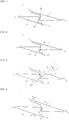
- Figs. 1 and 2 illustrate connections between blades on a bucket disposed on the outer peripheral surface of a rotor disk.
- the bucket generally comprises a coupling part that is coupled to the outer peripheral surface of the rotor disk in a dovetail manner.
- the coupling part has a platform formed at one end thereof, and the blades are disposed on the platform.
- Figs. 1 and 2 illustrate connections 4 and 5 between a plurality of blades 2 and 3.
- US 5257908 A shows an arrangement of turbine blades that are held in groups formed by a series of spaced lugs constituting a lashing structure. Selected lugs have gaps which are "Z"-shaped, the gaps tending to close during untwisting of the blades when the blades are subjected to high centrifugal forces.
- EP 2524759 A1 shows a pair of turbine buckets, each bucket including a Z-shaped front edge and a correspondingly-Z-shaped following edge. During operation of the turbine, following edge of the first bucket and front edge of the second bucket are in contact.
- the present disclosure has been made in view of the above-mentioned problem, and an object thereof is to provide a structure capable of damping vibration while performing variable contact according to the rotational speed of a turbine.
- the present disclosure is directed to a bucket vibration damping structure and a bucket and turbomachine having the same.
- the bucket vibration damping structure comprises a variable contact-type vibration damping means disposed on a plurality of bucket blades mounted on an outer peripheral surface of a rotor disk and performing variable contact according to rotational speed of a rotor for damping vibration, wherein the variable contact-type vibration damping means comprises a first damping member disposed on one of the blades, and a second damping member disposed at a position corresponding to the first damping member on the other blade.
- the first damping member may comprise a first tangential portion disposed on one blade and protruding toward the other adjacent blade, and a second tangential portion forming a certain angle with the first tangential portion and disposed adjacent thereto on one blade.
- Each of the first and second tangential portions may have a flat shape.
- the first and second tangential portions may form an angle of 90° to 120° with each other.
- the first and second tangential portions may have adjacent rounded portions.
- the second damping member may comprise a first facing portion protruding toward the first tangential portion on the other adjacent blade, and a second facing portion forming a certain angle with the first facing portion and disposed adjacent thereto.
- Each of the first and second facing portions may have a flat shape.
- the first and second facing portions may form an angle of 90° to 120° with each other.
- An amount of overlap between the first tangential portion and the first facing portion when they come into contact with each other may differ from an amount of overlap between the second tangential portion and the second facing portion when they come into contact with each other.
- the amount of overlap between the second tangential portion and the second facing portion when they come into contact with each other may be greater than the amount of overlap between the first tangential portion and the first facing portion when they come into contact with each other.
- An amount of gap between the first tangential portion and the first facing portion when they are not in contact with each other may differ from an amount of gap between the second tangential portion and the second facing portion when they are not in contact with each other.
- the amount of gap between the second tangential portion and the second facing portion when they are not in contact with each other may be greater than the amount of gap between the first tangential portion and the first facing portion when they are not in contact with each other.
- the first damping member may comprise a first curved portion disposed on one blade and rounded toward the other adjacent blade, and a second curved portion disposed adjacent to the first curved portion.
- the first and second curved portions may have the same curvature.
- the second damping member may comprise a first facing curved portion disposed on the other adjacent blade and rounded toward the first curved portion, and a second facing curved portion forming a certain angle with the first facing curved portion and disposed adjacent thereto.
- the first and second facing curved portions may have the same curvature.
- the curvature of the first and second facing curved portions may be greater than the curvature of the first and second curved portions.
- the bucket comprises a blade provided with the bucket vibration damping structure, a platform, one end of which is provided with the blade, and a coupling part provided at the other end of the platform and mounted on an outer peripheral surface of a rotor disk.
- the bucket vibration damping structure may be disposed on a shroud cover portion or an intermediate portion of the blade.
- the turbomachine comprises a casing, a compressor having the bucket and disposed in the casing to compress air introduced thereinto, a combustor connected to the compressor in the casing to combust the compressed air, a turbine connected to the combustor in the casing to produce power using the combusted air, and a diffuser connected to the turbine in the casing to discharge the air to the outside.
- the gas turbine pertaining to the present disclosure comprises a compressor, a combustor, and a turbine as basic components.
- the gas turbine has a casing corresponding to the body thereof.
- the compressor is disposed forward in the casing and the turbine is disposed rearward in the casing.
- the combustor is connected between the compressor and the turbine through respective passages in the casing.
- outside air is introduced into a compressor section disposed upstream of the gas turbine for an adiabatic compression process.
- the compressed air is introduced into a combustor section to be mixed with fuel for an isobaric combustion process.
- the combustion gas is introduced into a turbine section disposed downstream of the gas turbine for an adiabatic expansion process.
- the combustion used to produce power in the turbine is discharged to outside through an exhaust diffuser disposed in the rear of the casing.
- the compressor and the turbine are interconnected by one rotor shaft for rotation together.
- the gas turbine provided in a power plant is continuously driven to produce power. Therefore, the integral connection of the compressor and the turbine by a single rotor shaft may be suitable for manufacturing costs and management.
- a plurality of disks is mounted on the outer peripheral surface of the rotor shaft disposed in the compressor section, and a plurality of buckets corresponding to rotary wings is radially arranged on the disks.
- each of the buckets has a lower end processed in a dovetail form so that it is inserted into and coupled to a bucket mounting portion, which is formed on the outer peripheral surface of the associated disk, in the axial direction of the rotor shaft.
- the bucket is fitted into and coupled to the bucket mounting portion in the circumferential direction of the rotor disk.
- a platform is formed at the upper end of the bucket, and a blade is disposed on the platform.
- a plurality of disk diaphragms is fixedly arranged in rows on the inner peripheral surface of the casing, and a plurality of vanes or nozzles is radially arranged on the diaphragms.
- Each of the diaphragms has a hole formed at the center thereof such that the rotor shaft may be disposed therein.
- the air introduced from outside is compressed by mutual rotation of the vanes or nozzles disposed on the diaphragms and the buckets.
- the combustor section is disposed between the compressor section and the turbine section in the casing and is connected therebetween.
- a plurality of combustors is arranged in a shell form in the radial direction of the casing.
- Each of the combustors may comprise a burner that has a fuel injection nozzle and an ignition plug, an inner liner that defines a combustion chamber, a flow sleeve that guides the flow of combustion gas, and a transition piece that allows combustion gas to flow to the turbine section, etc.
- the air which is compressed in and introduced from the compressor section, is mixed with fuel injected from the combustor section for combustion and then flows to the turbine section.
- a plurality of turbine wheels is disposed on the outer peripheral surface of the rotor shaft disposed in the turbine section, and a plurality of turbine blades corresponding to rotary wings is radially arranged on the turbine wheels.
- a plurality of disk diaphragms is fixedly arranged in rows on the inner peripheral surface of the casing, and a plurality of vanes or nozzles is radially arranged on the diaphragms.
- Each of the diaphragms has a hole formed at the center thereof such that the rotor shaft may be disposed therein.
- the combustion gas generated in the combustors is expanded by mutual rotation of the vanes or nozzles disposed on the diaphragms and the turbine blades and is used to produce power in the turbine section.
- the gas turbine used in a combined generation system is configured such that the exhaust gas discharged from the exhaust diffuser is introduced into a steam turbine via heat exchangers for another power generation.
- the pressure and velocity of the exhaust gas discharged from the exhaust diffuser may be important factors. Therefore, the exhaust gas must be introduced into the steam turbine at constant pressure and velocity for smooth operation of the system.
- the non-rotation component such as a casing, a diaphragm, or a combustor is referred to as a fixed unit or a stator
- the rotation component such as a rotor shaft, a compressor, or a turbine is referred to as a rotating unit or a rotor.
- Fig. 3 is a view illustrating a vibration damping structure in a contact state at a low speed according to a first embodiment of the present disclosure.
- Fig. 4 is a view illustrating a vibration damping structure in another contact state at a high speed according to the first embodiment of the present disclosure.
- the vibration damping structure which is designated by reference numeral 10, according to the first embodiment of the present disclosure comprises a variable contact-type vibration damping means 11 that is disposed on a plurality of bucket blades 20 and 30 mounted on the outer peripheral surface of a rotor disk.
- the vibration damping structure performs a variable contact according to the rotational speed of a rotor for damping vibration.
- the variable contact-type vibration damping means 11 may comprise a first damping member 40 that is disposed on one of the blades, and a second damping member 50 that is disposed at a position corresponding to the first damping member 40 on the other blade.
- the first damping member 40 comprises a first tangential portion 41 and a second tangential portion 45
- the second damping member 50 comprises a first facing portion 51 and a second facing portion 55.
- the first tangential portion 41 may be disposed on one blade 20 and protrude toward the other adjacent blade 30, and the second tangential portion 45 may form a certain angle with the first tangential portion 41 and be disposed adjacent thereto on the blade 20.
- first and second tangential portions 41 and 45 may have a flat shape, which is to relieve vibration by forming contact surfaces with the first and second facing portions 51 and 55 as described below.
- the first and second tangential portions 41 and 45 form a certain angle ⁇ with each other.
- the certain angle ⁇ may be determined corresponding to the deformation of a bucket, the shape of which is deformed by a rotary force according to the increase or decrease of the rotational speed of a turbine.
- the certain angle ⁇ may be within a range of 90 to 120 degrees.
- the contact area of the overlap portion therebetween may be constantly maintained. Therefore, it may be possible to prevent the mutual separation between the first damping member 40 and the second damping member 50 even though the bucket is deformed.
- first and second tangential portions 41 and 45 have rounded portions 43 at the adjacent portions thereof.
- first and second tangential portions 41 and 45 are smoothly movable even when they come into the variable contact with the first and second facing portions 51 and 55.
- the first facing portion 51 may protrude toward the first tangential portion 41 on the other adjacent blade 30, and the second facing portion 55 may form a certain angle with the first facing portion 51 and be disposed adjacent thereto.
- first and second facing portions 51 and 55 may have a flat shape, which is to relieve vibration by forming contact surfaces with the first and second tangential portions 41 and 45.
- the first and second facing portions 51 and 55 form a certain angle ⁇ with each other.
- the certain angle ⁇ may be determined corresponding to the deformation of the bucket, the shape of which is deformed by rotary force according to the increase or decrease of the rotational speed of the turbine.
- the certain angle ⁇ may correspond to the angle formed by the first and second tangential portions 41 and 45.
- the certain angle ⁇ may be within a range of 90 to 120 degrees.
- the contact area of the overlap portion therebetween may be constantly maintained. Therefore, it may be possible to prevent the mutual separation between the first damping member 40 and the second damping member 50 even though the bucket is deformed.
- first and second facing portions 51 and 55 have rounded portions 53 at the adjacent portions thereof.
- first and second facing portions 51 and 55 are smoothly movable even when they come into variable contact with the first and second tangential portions 41 and 45.
- first and second damping members 40 and 50 may be configured such that an amount of overlap F1 between the first tangential portion 41 and the first facing portion 51 when they come into contact with each other differs from an amount of overlap F2 between the second tangential portion 45 and the second facing portion 55 when they come into contact with each other.
- This amount of overlap may be determined according to the degree of vibration caused by the rotational speed of the turbine. At a low speed, the vibration due to the impact with fluid is small since the rotational speed of the turbine is low. Thus, for relieving the vibration, the contact area between the damping members is relatively small.
- the amount of overlap F2 between the second tangential portion 45 and the second facing portion 55 when they come into contact with each other may be greater than the amount of overlap F1 between the first tangential portion 41 and the first facing portion 51 when they come into contact with each other.
- first and second damping members 40 and 50 may be configured such that an amount of gap A2 between the first tangential portion 41 and the first facing portion 51 when they are not in contact with each other differs from an amount of gap A1 between the second tangential portion 45 and the second facing portion 55 when they are not in contact with each other.
- This amount of gap may be determined according to the deformation of the bucket by the rotational speed of the turbine. The deformation of the bucket is further increased when the turbine rotates at the high speed. Therefore, in the first embodiment of the present disclosure, the amount of gap A1 between the second tangential portion 45 and the second facing portion 55 when they are not in contact with each other may be greater than the amount of gap A2 between the first tangential portion 41 and the first facing portion 51 when they are not in contact with each other.
- the vibration damping structure 10 may be disposed on cover portions X of shrouds 23 and 33 disposed at the ends of blades 20 and 30 of buckets 25 and 35 or on intermediate portions Y of the blades 20 and 30.
- the blades 20 and 30 are disposed on platforms 21 and 31, and male dovetail coupling parts 22 and 32 may be formed at the other sides of the platforms 21 and 31 so as to be coupled to the outer peripheral mounting portion of a rotor disk 70.
- the present disclosure may comprise these buckets.
- the present disclosure also pertains to a turbomachine comprising a casing, a compressor which has the buckets and is disposed in the casing to compress air introduced thereinto, a combustor which is connected to the compressor in the casing to combust the compressed air, a turbine which is connected to the combustor in the casing to produce power using the combusted air, and a diffuser which is connected to the turbine in the casing to discharge the air to outside.
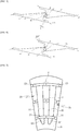
- Fig. 5 is a view illustrating a vibration damping structure in a contact state at a low speed according to a second embodiment of the present disclosure.
- Fig. 6 is a view illustrating a vibration damping structure in another contact state at a high speed according to the second embodiment of the present disclosure.
- the vibration damping structure which is designated by reference numeral 10, according to the second embodiment of the present disclosure comprises a variable contact-type vibration damping means 11 that is disposed on a plurality of bucket blades 20 and 30 mounted on the outer peripheral surface of a rotor disk and performs variable contact according to the rotational speed of a rotor for damping vibration.
- the variable contact-type vibration damping means 11 comprises a first damping member 40 that is disposed on one of the blades, and a second damping member 50 that is disposed at a position corresponding to the first damping member 40 on the other blade.
- the first damping member 40 comprises a first curved portion 46 and a second curved portion 49
- the second damping member 50 comprises a first facing curved portion 56 and a second facing curved portion 59.
- the first curved portion 46 may be disposed on one blade 20 and be rounded toward the other adjacent blade 30, and the second curved portion 49 may be disposed adjacent to the first curved portion 46.
- first and second curved portions 46 and 49 may have a semi-circular shape, which is to relieve vibration by forming contact surfaces with the first and second facing curved portions 56 and 59 as described below.
- the first and second curved portions 46 and 49 have the same curvature K1, which is to smoothly move when they form the contact surfaces with the first and second facing curved portions 56 and 59. That is, even though the first and second curved portions 46 and 49 come into a variable contact with the first and second facing curved portions 56 and 59 within a variation range of rotational speed (e.g., within a range of 1800 to 3600 rpm), the contact area of the overlap portion therebetween may be constantly maintained by virtue of the same curvature. Therefore, it may be possible to prevent the mutual separation between the first damping member 40 and the second damping member 50 even though the bucket is deformed.
- a variation range of rotational speed e.g., within a range of 1800 to 3600 rpm
- the first facing curved portion 56 may be rounded toward the first curved portion 46 on the other adjacent blade 30, and the second facing curved portion 59 may be disposed adjacent to the first facing curved portion 56.
- the first and second facing curved portions 56 and 59 may have the same curvature K2, which is to relieve vibration by forming contact surfaces with the first and second curved portions 46 and 49.
- the same curvature allows the first and second facing curved portions 56 and 59 to smoothly move.
- first and second curved portions 46 and 49 come into the variable contact with the first and second facing curved portions 56 and 59 within a variation range of rotational speed (e.g., within a range of 1800 to 3600 rpm), the contact area of the overlap portion therebetween may be constantly maintained. Therefore, it may be possible to prevent the mutual separation between the first damping member 40 and the second damping member 50 even though the bucket is deformed.
- a variation range of rotational speed e.g., within a range of 1800 to 3600 rpm
- first and second damping members 40 and 50 may be configured such that the curvature K2 of the first and second facing curved portions 56 and 59 is greater than the curvature K1 of the first and second curved portions 46 and 49.
- first and second damping members may come into the variable contact with each other with respect to the increase or decrease of the rotational speed of the turbine by forming a gap which is a non-contact area therebetween.
- the curvature K2 is greater than the curvature K1.
- first and second damping members 40 and 50 may be configured such that an amount of gap B2 between the first curved portion 46 and the first facing curved portion 56 when they are not in contact with each other differs from an amount of gap B1 between the second curved portion 49 and the second facing curved portion 59 when they are not in contact with each other.
- This amount of gap may be determined according to the deformation of the bucket by the rotational speed of the turbine. The deformation of the bucket is further increased when the turbine rotates at the high speed. Therefore, in the second embodiment of the present disclosure, the amount of gap B1 between the second curved portion 49 and the second facing curved portion 59 when they are not in contact with each other may be greater than the amount of gap B2 between the first curved portion 46 and the first facing curved portion 56 when they are not in contact with each other.
- the vibration damping structure 10 may be disposed on the cover portions X of the shrouds 23 and 33 disposed at the ends of the blades 20 and 30 of the buckets 25 and 35 or on the intermediate portions Y of the blades 20 and 30.
- the blades 20 and 30 are disposed on the platforms 21 and 31, and the male dovetail coupling parts 22 and 32 may be formed at the other sides of the platforms 21 and 31 so as to be coupled to the outer peripheral mounting portion of the rotor disk 70.
- the present disclosure may comprise these buckets.
- the present disclosure also pertains to the turbomachine comprising the casing, the compressor which has the buckets and is disposed in the casing to compress air introduced thereinto, the combustor which is connected to the compressor in the casing to combust the compressed air, the turbine which is connected to the combustor in the casing to produce power using the combusted air, and the diffuser which is connected to the turbine in the casing to discharge the air to outside.
- the present disclosure can damp vibration by connecting a plurality of blades while one surfaces thereof come into contact with each other at a low speed and can damp vibration by connecting the plurality of blades while the other surfaces thereof come into contact with each other when buckets are deformed by rotary force at a high speed.
Landscapes
- Engineering & Computer Science (AREA)
- Mechanical Engineering (AREA)
- General Engineering & Computer Science (AREA)
- Chemical & Material Sciences (AREA)
- Combustion & Propulsion (AREA)
- Turbine Rotor Nozzle Sealing (AREA)
- Structures Of Non-Positive Displacement Pumps (AREA)
Claims (13)
- Structure d'amortissement de vibrations d'aubes (10) comportant :des moyens d'amortissement de vibrations de type à contact variable (11) disposés sur une pluralité de lames d'aubes (20, 30) montées sur une surface périphérique extérieure d'un disque de rotor (70) et assurant un contact variable en fonction d'une vitesse de rotation d'un rotor pour amortir les vibrations,dans laquelle les moyens d'amortissement de vibrations de type à contact variable (11) comportent :un premier élément d'amortissement (40) disposé sur une lame (20) de la pluralité de lames d'aubes (20, 30) ; etun second élément d'amortissement (50) disposé sur une autre lame (30) de la pluralité de lames d'aubes (20, 30) à une position correspondant au premier élément d'amortissement (40) sur la lame (20) ;caractérisée en ce que le premier élément d'amortissement (40) comporte une première partie tangentielle (41) et une seconde partie tangentielle (45) et le second élément d'amortissement (50) comporte une première partie faciale (51) et une seconde partie faciale (55), dans laquelle la première partie tangentielle (41) est configurée pour venir en contact avec la première partie faciale (51) à une petite vitesse de rotation du rotor et la seconde partie tangentielle (45) est configurée pour venir en contact avec la seconde partie faciale (55) à une grande vitesse de rotation du rotor, dans les limites d'une plage de variation de la vitesse de rotation ; etdans laquelle la première partie tangentielle (41) est disposée sur la lame (20) et fait saillie vers l'autre lame (30), etdans laquelle la seconde partie tangentielle (45) forme un certain angle (φ) variant de 90° à 120° avec la première partie tangentielle (41) et est disposée au voisinage de celle-ci sur la lame (20).
- Structure d'amortissement de vibrations d'aubes (10) selon la revendication 1, dans laquelle les première et seconde parties tangentielles (41, 45) ont des parties arrondies (43) adjacentes.
- Structure d'amortissement de vibrations d'aubes (10) selon la revendication 1, dans laquelle la première partie faciale (51) fait saillie vers la première partie tangentielle (41) sur l'autre lame ; et
la seconde partie faciale (55) forme un certain angle (φ) avec la première partie faciale (51) et est disposée au voisinage de celle-ci. - Structure d'amortissement de vibrations d'aubes (10) selon la revendication 3, dans laquelle chacune des première et seconde parties faciales (51, 55) a une forme plate et/ou dans laquelle chacune des première et seconde parties tangentielles (41, 45) a une forme plate.
- Structure d'amortissement de vibrations d'aubes (10) selon la revendication 3 ou 4, dans laquelle les première et seconde parties faciales (51, 55) forment l'angle spécifique (φ) variant de 90° à 120° l'une par rapport à l'autre.
- Structure d'amortissement de vibrations d'aubes (10) selon les revendications 3 à 5, dans laquelle une quantité de chevauchement (F1) entre la première partie tangentielle (41) et la première partie faciale (51) lorsqu'elles viennent en contact l'une avec l'autre diffère d'une quantité de chevauchement (F2) entre la seconde partie tangentielle (45) et la seconde partie faciale (55) lorsqu'elles viennent en contact l'une avec l'autre.
- Structure d'amortissement de vibrations d'aubes (10) selon la revendication 6, dans laquelle la quantité de chevauchement (F2) entre la seconde partie tangentielle (45) et la seconde partie faciale (55) lorsqu'elles viennent en contact l'une avec l'autre est plus grande que la quantité de chevauchement (F1) entre la première partie tangentielle (41) et la première partie faciale (51) lorsqu'elles viennent en contact l'une avec l'autre.
- Structure d'amortissement de vibrations d'aubes (10) selon les revendications 3 à 7, dans laquelle une quantité d'espace (A2) entre la première partie tangentielle (41) et la première partie faciale (51) lorsqu'elles ne sont pas en contact l'une avec l'autre diffère d'une quantité d'espace (A1) entre la seconde partie tangentielle (51) et la seconde partie faciale (55) lorsqu'elles ne sont pas en contact l'une avec l'autre.
- Structure d'amortissement de vibrations d'aubes (10) selon la revendication 8, dans laquelle la quantité d'espace (A1) entre la seconde partie tangentielle (45) et la seconde partie faciale (55) lorsqu'elles ne sont pas en contact l'une avec l'autre est plus grande que la quantité d'espace (A2) entre la première partie tangentielle (41) et la première partie faciale (55) lorsqu'elles ne sont pas en contact l'une avec l'autre.
- Structure d'amortissement de vibrations d'aubes (10) comportant :des moyens d'amortissement de vibrations de type à contact variable (11) disposés sur une pluralité de lames d'aubes (20, 30) montées sur une surface périphérique extérieure d'un disque de rotor (70) et assurant un contact variable en fonction d'une vitesse de rotation d'un rotor pour amortir les vibrations,dans laquelle les moyens d'amortissement de vibrations de type à contact variable (11) comportent :un premier élément d'amortissement (40) disposé sur une lame (20) de la pluralité de lames d'aubes (20, 30) ; etun second élément d'amortissement (50) disposé sur une autre lame (30) de la pluralité de lames d'aubes (20, 30) à une position correspondant au premier élément d'amortissement (40) sur la lame (20) ;caractérisée en ce que le premier élément d'amortissement (40) comporte une première partie courbe (46) et une seconde partie courbe (49) et le second élément d'amortissement (50) comporte une première partie courbe faciale (56) et une seconde partie courbe faciale (59), dans laquelle la première partie courbe (46) est configurée pour venir en contact avec la première partie courbe faciale (56) à une petite vitesse de rotation du rotor et la seconde partie courbe (49) est configurée pour venir en contact avec la seconde partie courbe faciale (59) à une grande vitesse de rotation du rotor, dans les limites d'une plage de variation de la vitesse de rotation ; etdans laquelle la première partie courbe (46) est disposée sur la lame (20) et est arrondie vers l'autre lame (30) ; etla seconde partie courbe (49) est disposée au voisinage de la première partie courbe (46).
- Structure d'amortissement de vibrations d'aubes (10) selon la revendication 10, dans laquelle la première partie courbe faciale (56) est disposée sur l'autre lame (30) et arrondie vers la première partie courbe (46) ; et
la seconde partie courbe faciale (59) forme un certain angle avec la première partie courbe faciale (56) et est disposée au voisinage de celle-ci. - Structure d'amortissement de vibrations d'aubes (10) selon la revendication 11, dans laquelle la courbure (K2) des première et seconde parties courbes faciales (56, 59) est plus grande que la courbure (K1) des première et seconde parties courbes (46, 49).
- Turbomachine comportant :- un carter,- un compresseur ayant les aubes et disposé dans le carter pour comprimer de l'air introduit dans celui-ci,- une chambre de combustion reliée au compresseur dans le carter pour brûler l'air comprimé,- une turbine reliée à la chambre de combustion dans le carter pour produire de la puissance en utilisant l'air brûlé, et un diffuseur relié à la turbine dans le carter pour évacuer l'air vers l'extérieur ;caractérisée en ce que
la turbomachine comporte une structure d'amortissement de vibrations d'aubes (10) soit selon l'une quelconque des revendications 1 à 9, soit selon la revendication 10.
Applications Claiming Priority (1)
| Application Number | Priority Date | Filing Date | Title |
|---|---|---|---|
| KR1020170041742A KR101874243B1 (ko) | 2017-03-31 | 2017-03-31 | 버킷의 진동감쇠구조와 이를 포함하는 버킷 및 터보머신 |
Publications (2)
| Publication Number | Publication Date |
|---|---|
| EP3382144A1 EP3382144A1 (fr) | 2018-10-03 |
| EP3382144B1 true EP3382144B1 (fr) | 2020-04-15 |
Family
ID=61750016
Family Applications (1)
| Application Number | Title | Priority Date | Filing Date |
|---|---|---|---|
| EP18163286.0A Active EP3382144B1 (fr) | 2017-03-31 | 2018-03-22 | Structure d'amortissement de vibrations d'ailettes, ailette et turbomachine les comportant |
Country Status (3)
| Country | Link |
|---|---|
| US (1) | US10677072B2 (fr) |
| EP (1) | EP3382144B1 (fr) |
| KR (1) | KR101874243B1 (fr) |
Families Citing this family (3)
| Publication number | Priority date | Publication date | Assignee | Title |
|---|---|---|---|---|
| US11719440B2 (en) * | 2018-12-19 | 2023-08-08 | Doosan Enerbility Co., Ltd. | Pre-swirler having dimples |
| FR3107921B1 (fr) * | 2020-03-04 | 2022-08-05 | Safran Aircraft Engines | Procede pour remboiter des talons d’aubes d’une roue de rotor dans une turbomachine d’aeronef |
| DE102021118184A1 (de) * | 2021-07-14 | 2023-01-19 | MTU Aero Engines AG | Laufschaufel für eine strömungsmaschine |
Family Cites Families (16)
| Publication number | Priority date | Publication date | Assignee | Title |
|---|---|---|---|---|
| US4710102A (en) * | 1984-11-05 | 1987-12-01 | Ortolano Ralph J | Connected turbine shrouding |
| FR2612249B1 (fr) * | 1987-03-12 | 1992-02-07 | Alsthom | Aubage mobile pour turbines a vapeur |
| US5257908A (en) * | 1991-11-15 | 1993-11-02 | Ortolano Ralph J | Turbine lashing structure |
| US5522705A (en) * | 1994-05-13 | 1996-06-04 | United Technologies Corporation | Friction damper for gas turbine engine blades |
| JP2002004802A (ja) * | 2000-06-21 | 2002-01-09 | Mitsubishi Heavy Ind Ltd | 回転翼のシュラウド |
| JP2004052757A (ja) | 2002-05-31 | 2004-02-19 | Toshiba Corp | タービン動翼 |
| JP2005256786A (ja) * | 2004-03-12 | 2005-09-22 | Mitsubishi Heavy Ind Ltd | 回転機械、及び、回転機械の連成方法 |
| US7220100B2 (en) * | 2005-04-14 | 2007-05-22 | General Electric Company | Crescentic ramp turbine stage |
| DE102008023326A1 (de) * | 2008-05-13 | 2009-11-19 | Mtu Aero Engines Gmbh | Deckband für Laufschaufeln einer Strömungsmaschine und Strömungsmaschine |
| US9194239B2 (en) | 2010-01-20 | 2015-11-24 | Mitsubishi Heavy Industries, Ltd. | Turbine rotor blade and turbo machine |
| US20120294729A1 (en) * | 2011-05-16 | 2012-11-22 | General Electric Company | Cold metal transfer hardfacing of buckets |
| WO2014105533A1 (fr) * | 2012-12-28 | 2014-07-03 | United Technologies Corporation | Aube de turbine renforcée avec coin coupé |
| JP2015075070A (ja) | 2013-10-11 | 2015-04-20 | 株式会社東芝 | 蒸気タービン |
| US9822647B2 (en) | 2014-01-29 | 2017-11-21 | General Electric Company | High chord bucket with dual part span shrouds and curved dovetail |
| JP6066948B2 (ja) | 2014-03-13 | 2017-01-25 | 三菱重工業株式会社 | シュラウド、動翼体、及び回転機械 |
| US10196908B2 (en) * | 2016-02-09 | 2019-02-05 | General Electric Company | Turbine bucket having part-span connector and profile |
-
2017
- 2017-03-31 KR KR1020170041742A patent/KR101874243B1/ko active IP Right Grant
-
2018
- 2018-03-13 US US15/919,212 patent/US10677072B2/en active Active
- 2018-03-22 EP EP18163286.0A patent/EP3382144B1/fr active Active
Non-Patent Citations (1)
| Title |
|---|
| None * |
Also Published As
| Publication number | Publication date |
|---|---|
| EP3382144A1 (fr) | 2018-10-03 |
| US20180283186A1 (en) | 2018-10-04 |
| US10677072B2 (en) | 2020-06-09 |
| KR101874243B1 (ko) | 2018-07-03 |
Similar Documents
| Publication | Publication Date | Title |
|---|---|---|
| EP2971693B1 (fr) | Dispositif d'étanchéité de disque de rotor de turbine à gaz | |
| KR101919228B1 (ko) | 버킷의 축 방향 고정 장치와 버킷 조립체 및 이를 포함하는 가스터빈 | |
| EP3382144B1 (fr) | Structure d'amortissement de vibrations d'ailettes, ailette et turbomachine les comportant | |
| EP2666971A1 (fr) | Turbomachine dotée d'une capacité de commande de jeu | |
| KR101985093B1 (ko) | 블레이드 팁의 실링구조와 이를 포함하는 가스터빈 | |
| US10914182B2 (en) | Gas turbine | |
| EP3470625B1 (fr) | Ensemble de disque de rotor pour turbine à gaz | |
| US10927678B2 (en) | Turbine vane having improved flexibility | |
| US11415010B1 (en) | Turbine nozzle and gas turbine including the same | |
| US11401826B2 (en) | Stator structure and gas turbine having the same | |
| KR102454379B1 (ko) | 로터 및 이를 포함하는 터보머신 | |
| KR102307578B1 (ko) | 터빈 베인 및 이를 포함하는 터빈 베인 어셈블리 | |
| KR102655158B1 (ko) | 씰링 어셈블리 및 이를 포함하는 터보머신 | |
| KR102031933B1 (ko) | 블레이드 및 이를 구비하는 압축기 및 가스터빈 | |
| KR102120097B1 (ko) | 가스 터빈의 고정 베인 노즐 | |
| EP3885533A1 (fr) | Aube rotorique pour une turbomachine et turbomachine associée | |
| CN107532478B (zh) | 用于设计流体流发动机的方法和流体流发动机 | |
| KR20240026652A (ko) | 로터 및 이를 포함하는 터보머신 | |
| KR20190082501A (ko) | 로터 디스크에 대한 블레이드 고정 구조 |
Legal Events
| Date | Code | Title | Description |
|---|---|---|---|
| PUAI | Public reference made under article 153(3) epc to a published international application that has entered the european phase |
Free format text: ORIGINAL CODE: 0009012 |
|
| STAA | Information on the status of an ep patent application or granted ep patent |
Free format text: STATUS: REQUEST FOR EXAMINATION WAS MADE |
|
| 17P | Request for examination filed |
Effective date: 20180322 |
|
| AK | Designated contracting states |
Kind code of ref document: A1 Designated state(s): AL AT BE BG CH CY CZ DE DK EE ES FI FR GB GR HR HU IE IS IT LI LT LU LV MC MK MT NL NO PL PT RO RS SE SI SK SM TR |
|
| AX | Request for extension of the european patent |
Extension state: BA ME |
|
| STAA | Information on the status of an ep patent application or granted ep patent |
Free format text: STATUS: EXAMINATION IS IN PROGRESS |
|
| RBV | Designated contracting states (corrected) |
Designated state(s): AL AT BE BG CH CY CZ DE DK EE ES FI FR GB GR HR HU IE IS IT LI LT LU LV MC MK MT NL NO PL PT RO RS SE SI SK SM TR |
|
| 17Q | First examination report despatched |
Effective date: 20181023 |
|
| GRAP | Despatch of communication of intention to grant a patent |
Free format text: ORIGINAL CODE: EPIDOSNIGR1 |
|
| STAA | Information on the status of an ep patent application or granted ep patent |
Free format text: STATUS: GRANT OF PATENT IS INTENDED |
|
| INTG | Intention to grant announced |
Effective date: 20191018 |
|
| GRAS | Grant fee paid |
Free format text: ORIGINAL CODE: EPIDOSNIGR3 |
|
| GRAA | (expected) grant |
Free format text: ORIGINAL CODE: 0009210 |
|
| STAA | Information on the status of an ep patent application or granted ep patent |
Free format text: STATUS: THE PATENT HAS BEEN GRANTED |
|
| AK | Designated contracting states |
Kind code of ref document: B1 Designated state(s): AL AT BE BG CH CY CZ DE DK EE ES FI FR GB GR HR HU IE IS IT LI LT LU LV MC MK MT NL NO PL PT RO RS SE SI SK SM TR |
|
| REG | Reference to a national code |
Ref country code: CH Ref legal event code: EP |
|
| REG | Reference to a national code |
Ref country code: DE Ref legal event code: R096 Ref document number: 602018003696 Country of ref document: DE |
|
| REG | Reference to a national code |
Ref country code: IE Ref legal event code: FG4D |
|
| REG | Reference to a national code |
Ref country code: AT Ref legal event code: REF Ref document number: 1257509 Country of ref document: AT Kind code of ref document: T Effective date: 20200515 |
|
| REG | Reference to a national code |
Ref country code: NL Ref legal event code: MP Effective date: 20200415 |
|
| REG | Reference to a national code |
Ref country code: LT Ref legal event code: MG4D |
|
| PG25 | Lapsed in a contracting state [announced via postgrant information from national office to epo] |
Ref country code: IS Free format text: LAPSE BECAUSE OF FAILURE TO SUBMIT A TRANSLATION OF THE DESCRIPTION OR TO PAY THE FEE WITHIN THE PRESCRIBED TIME-LIMIT Effective date: 20200815 Ref country code: NO Free format text: LAPSE BECAUSE OF FAILURE TO SUBMIT A TRANSLATION OF THE DESCRIPTION OR TO PAY THE FEE WITHIN THE PRESCRIBED TIME-LIMIT Effective date: 20200715 Ref country code: SE Free format text: LAPSE BECAUSE OF FAILURE TO SUBMIT A TRANSLATION OF THE DESCRIPTION OR TO PAY THE FEE WITHIN THE PRESCRIBED TIME-LIMIT Effective date: 20200415 Ref country code: FI Free format text: LAPSE BECAUSE OF FAILURE TO SUBMIT A TRANSLATION OF THE DESCRIPTION OR TO PAY THE FEE WITHIN THE PRESCRIBED TIME-LIMIT Effective date: 20200415 Ref country code: GR Free format text: LAPSE BECAUSE OF FAILURE TO SUBMIT A TRANSLATION OF THE DESCRIPTION OR TO PAY THE FEE WITHIN THE PRESCRIBED TIME-LIMIT Effective date: 20200716 Ref country code: LT Free format text: LAPSE BECAUSE OF FAILURE TO SUBMIT A TRANSLATION OF THE DESCRIPTION OR TO PAY THE FEE WITHIN THE PRESCRIBED TIME-LIMIT Effective date: 20200415 Ref country code: NL Free format text: LAPSE BECAUSE OF FAILURE TO SUBMIT A TRANSLATION OF THE DESCRIPTION OR TO PAY THE FEE WITHIN THE PRESCRIBED TIME-LIMIT Effective date: 20200415 Ref country code: PT Free format text: LAPSE BECAUSE OF FAILURE TO SUBMIT A TRANSLATION OF THE DESCRIPTION OR TO PAY THE FEE WITHIN THE PRESCRIBED TIME-LIMIT Effective date: 20200817 |
|
| REG | Reference to a national code |
Ref country code: AT Ref legal event code: MK05 Ref document number: 1257509 Country of ref document: AT Kind code of ref document: T Effective date: 20200415 |
|
| PG25 | Lapsed in a contracting state [announced via postgrant information from national office to epo] |
Ref country code: RS Free format text: LAPSE BECAUSE OF FAILURE TO SUBMIT A TRANSLATION OF THE DESCRIPTION OR TO PAY THE FEE WITHIN THE PRESCRIBED TIME-LIMIT Effective date: 20200415 Ref country code: LV Free format text: LAPSE BECAUSE OF FAILURE TO SUBMIT A TRANSLATION OF THE DESCRIPTION OR TO PAY THE FEE WITHIN THE PRESCRIBED TIME-LIMIT Effective date: 20200415 Ref country code: BG Free format text: LAPSE BECAUSE OF FAILURE TO SUBMIT A TRANSLATION OF THE DESCRIPTION OR TO PAY THE FEE WITHIN THE PRESCRIBED TIME-LIMIT Effective date: 20200715 Ref country code: HR Free format text: LAPSE BECAUSE OF FAILURE TO SUBMIT A TRANSLATION OF THE DESCRIPTION OR TO PAY THE FEE WITHIN THE PRESCRIBED TIME-LIMIT Effective date: 20200415 |
|
| PG25 | Lapsed in a contracting state [announced via postgrant information from national office to epo] |
Ref country code: AL Free format text: LAPSE BECAUSE OF FAILURE TO SUBMIT A TRANSLATION OF THE DESCRIPTION OR TO PAY THE FEE WITHIN THE PRESCRIBED TIME-LIMIT Effective date: 20200415 |
|
| REG | Reference to a national code |
Ref country code: DE Ref legal event code: R097 Ref document number: 602018003696 Country of ref document: DE |
|
| PG25 | Lapsed in a contracting state [announced via postgrant information from national office to epo] |
Ref country code: IT Free format text: LAPSE BECAUSE OF FAILURE TO SUBMIT A TRANSLATION OF THE DESCRIPTION OR TO PAY THE FEE WITHIN THE PRESCRIBED TIME-LIMIT Effective date: 20200415 Ref country code: EE Free format text: LAPSE BECAUSE OF FAILURE TO SUBMIT A TRANSLATION OF THE DESCRIPTION OR TO PAY THE FEE WITHIN THE PRESCRIBED TIME-LIMIT Effective date: 20200415 Ref country code: SM Free format text: LAPSE BECAUSE OF FAILURE TO SUBMIT A TRANSLATION OF THE DESCRIPTION OR TO PAY THE FEE WITHIN THE PRESCRIBED TIME-LIMIT Effective date: 20200415 Ref country code: DK Free format text: LAPSE BECAUSE OF FAILURE TO SUBMIT A TRANSLATION OF THE DESCRIPTION OR TO PAY THE FEE WITHIN THE PRESCRIBED TIME-LIMIT Effective date: 20200415 Ref country code: ES Free format text: LAPSE BECAUSE OF FAILURE TO SUBMIT A TRANSLATION OF THE DESCRIPTION OR TO PAY THE FEE WITHIN THE PRESCRIBED TIME-LIMIT Effective date: 20200415 Ref country code: AT Free format text: LAPSE BECAUSE OF FAILURE TO SUBMIT A TRANSLATION OF THE DESCRIPTION OR TO PAY THE FEE WITHIN THE PRESCRIBED TIME-LIMIT Effective date: 20200415 Ref country code: RO Free format text: LAPSE BECAUSE OF FAILURE TO SUBMIT A TRANSLATION OF THE DESCRIPTION OR TO PAY THE FEE WITHIN THE PRESCRIBED TIME-LIMIT Effective date: 20200415 |
|
| PLBE | No opposition filed within time limit |
Free format text: ORIGINAL CODE: 0009261 |
|
| STAA | Information on the status of an ep patent application or granted ep patent |
Free format text: STATUS: NO OPPOSITION FILED WITHIN TIME LIMIT |
|
| PG25 | Lapsed in a contracting state [announced via postgrant information from national office to epo] |
Ref country code: SK Free format text: LAPSE BECAUSE OF FAILURE TO SUBMIT A TRANSLATION OF THE DESCRIPTION OR TO PAY THE FEE WITHIN THE PRESCRIBED TIME-LIMIT Effective date: 20200415 Ref country code: PL Free format text: LAPSE BECAUSE OF FAILURE TO SUBMIT A TRANSLATION OF THE DESCRIPTION OR TO PAY THE FEE WITHIN THE PRESCRIBED TIME-LIMIT Effective date: 20200415 |
|
| 26N | No opposition filed |
Effective date: 20210118 |
|
| PG25 | Lapsed in a contracting state [announced via postgrant information from national office to epo] |
Ref country code: SI Free format text: LAPSE BECAUSE OF FAILURE TO SUBMIT A TRANSLATION OF THE DESCRIPTION OR TO PAY THE FEE WITHIN THE PRESCRIBED TIME-LIMIT Effective date: 20200415 |
|
| PG25 | Lapsed in a contracting state [announced via postgrant information from national office to epo] |
Ref country code: MC Free format text: LAPSE BECAUSE OF FAILURE TO SUBMIT A TRANSLATION OF THE DESCRIPTION OR TO PAY THE FEE WITHIN THE PRESCRIBED TIME-LIMIT Effective date: 20200415 |
|
| REG | Reference to a national code |
Ref country code: CH Ref legal event code: PL |
|
| REG | Reference to a national code |
Ref country code: BE Ref legal event code: MM Effective date: 20210331 |
|
| PG25 | Lapsed in a contracting state [announced via postgrant information from national office to epo] |
Ref country code: FR Free format text: LAPSE BECAUSE OF NON-PAYMENT OF DUE FEES Effective date: 20210331 Ref country code: CH Free format text: LAPSE BECAUSE OF NON-PAYMENT OF DUE FEES Effective date: 20210331 Ref country code: LU Free format text: LAPSE BECAUSE OF NON-PAYMENT OF DUE FEES Effective date: 20210322 Ref country code: IE Free format text: LAPSE BECAUSE OF NON-PAYMENT OF DUE FEES Effective date: 20210322 Ref country code: LI Free format text: LAPSE BECAUSE OF NON-PAYMENT OF DUE FEES Effective date: 20210331 |
|
| PG25 | Lapsed in a contracting state [announced via postgrant information from national office to epo] |
Ref country code: BE Free format text: LAPSE BECAUSE OF NON-PAYMENT OF DUE FEES Effective date: 20210331 |
|
| GBPC | Gb: european patent ceased through non-payment of renewal fee |
Effective date: 20220322 |
|
| PG25 | Lapsed in a contracting state [announced via postgrant information from national office to epo] |
Ref country code: GB Free format text: LAPSE BECAUSE OF NON-PAYMENT OF DUE FEES Effective date: 20220322 |
|
| PG25 | Lapsed in a contracting state [announced via postgrant information from national office to epo] |
Ref country code: CY Free format text: LAPSE BECAUSE OF FAILURE TO SUBMIT A TRANSLATION OF THE DESCRIPTION OR TO PAY THE FEE WITHIN THE PRESCRIBED TIME-LIMIT Effective date: 20200415 |
|
| PG25 | Lapsed in a contracting state [announced via postgrant information from national office to epo] |
Ref country code: HU Free format text: LAPSE BECAUSE OF FAILURE TO SUBMIT A TRANSLATION OF THE DESCRIPTION OR TO PAY THE FEE WITHIN THE PRESCRIBED TIME-LIMIT; INVALID AB INITIO Effective date: 20180322 |
|
| PG25 | Lapsed in a contracting state [announced via postgrant information from national office to epo] |
Ref country code: MK Free format text: LAPSE BECAUSE OF FAILURE TO SUBMIT A TRANSLATION OF THE DESCRIPTION OR TO PAY THE FEE WITHIN THE PRESCRIBED TIME-LIMIT Effective date: 20200415 |
|
| PGFP | Annual fee paid to national office [announced via postgrant information from national office to epo] |
Ref country code: CZ Payment date: 20240228 Year of fee payment: 7 Ref country code: DE Payment date: 20231229 Year of fee payment: 7 |