EP3382107B1 - Construction machine with a control system for the superstructure - Google Patents
Construction machine with a control system for the superstructure Download PDFInfo
- Publication number
- EP3382107B1 EP3382107B1 EP16868413.2A EP16868413A EP3382107B1 EP 3382107 B1 EP3382107 B1 EP 3382107B1 EP 16868413 A EP16868413 A EP 16868413A EP 3382107 B1 EP3382107 B1 EP 3382107B1
- Authority
- EP
- European Patent Office
- Prior art keywords
- swing
- angle
- work implement
- signal
- stop
- Prior art date
- Legal status (The legal status is an assumption and is not a legal conclusion. Google has not performed a legal analysis and makes no representation as to the accuracy of the status listed.)
- Active
Links
- 238000010276 construction Methods 0.000 title claims description 46
- 230000009471 action Effects 0.000 claims description 30
- 239000012530 fluid Substances 0.000 claims description 16
- 230000009466 transformation Effects 0.000 description 23
- 238000010586 diagram Methods 0.000 description 22
- 230000008602 contraction Effects 0.000 description 11
- 238000012545 processing Methods 0.000 description 11
- 238000000605 extraction Methods 0.000 description 10
- 238000000034 method Methods 0.000 description 10
- 238000012937 correction Methods 0.000 description 8
- 230000008878 coupling Effects 0.000 description 5
- 238000010168 coupling process Methods 0.000 description 5
- 238000005859 coupling reaction Methods 0.000 description 5
- 230000004044 response Effects 0.000 description 5
- 238000009412 basement excavation Methods 0.000 description 2
- 230000003111 delayed effect Effects 0.000 description 2
- 239000000284 extract Substances 0.000 description 2
- 238000013459 approach Methods 0.000 description 1
- 230000007423 decrease Effects 0.000 description 1
- 230000003292 diminished effect Effects 0.000 description 1
- 238000012986 modification Methods 0.000 description 1
- 230000004048 modification Effects 0.000 description 1
- 238000012544 monitoring process Methods 0.000 description 1
- 230000009467 reduction Effects 0.000 description 1
Images


Classifications
-
- E—FIXED CONSTRUCTIONS
- E02—HYDRAULIC ENGINEERING; FOUNDATIONS; SOIL SHIFTING
- E02F—DREDGING; SOIL-SHIFTING
- E02F9/00—Component parts of dredgers or soil-shifting machines, not restricted to one of the kinds covered by groups E02F3/00 - E02F7/00
- E02F9/20—Drives; Control devices
- E02F9/2025—Particular purposes of control systems not otherwise provided for
- E02F9/2033—Limiting the movement of frames or implements, e.g. to avoid collision between implements and the cabin
-
- B—PERFORMING OPERATIONS; TRANSPORTING
- B66—HOISTING; LIFTING; HAULING
- B66C—CRANES; LOAD-ENGAGING ELEMENTS OR DEVICES FOR CRANES, CAPSTANS, WINCHES, OR TACKLES
- B66C23/00—Cranes comprising essentially a beam, boom, or triangular structure acting as a cantilever and mounted for translatory of swinging movements in vertical or horizontal planes or a combination of such movements, e.g. jib-cranes, derricks, tower cranes
- B66C23/62—Constructional features or details
- B66C23/84—Slewing gear
- B66C23/86—Slewing gear hydraulically actuated
-
- E—FIXED CONSTRUCTIONS
- E02—HYDRAULIC ENGINEERING; FOUNDATIONS; SOIL SHIFTING
- E02F—DREDGING; SOIL-SHIFTING
- E02F3/00—Dredgers; Soil-shifting machines
- E02F3/04—Dredgers; Soil-shifting machines mechanically-driven
- E02F3/28—Dredgers; Soil-shifting machines mechanically-driven with digging tools mounted on a dipper- or bucket-arm, i.e. there is either one arm or a pair of arms, e.g. dippers, buckets
- E02F3/30—Dredgers; Soil-shifting machines mechanically-driven with digging tools mounted on a dipper- or bucket-arm, i.e. there is either one arm or a pair of arms, e.g. dippers, buckets with a dipper-arm pivoted on a cantilever beam, i.e. boom
- E02F3/32—Dredgers; Soil-shifting machines mechanically-driven with digging tools mounted on a dipper- or bucket-arm, i.e. there is either one arm or a pair of arms, e.g. dippers, buckets with a dipper-arm pivoted on a cantilever beam, i.e. boom working downwardly and towards the machine, e.g. with backhoes
-
- E—FIXED CONSTRUCTIONS
- E02—HYDRAULIC ENGINEERING; FOUNDATIONS; SOIL SHIFTING
- E02F—DREDGING; SOIL-SHIFTING
- E02F3/00—Dredgers; Soil-shifting machines
- E02F3/04—Dredgers; Soil-shifting machines mechanically-driven
- E02F3/28—Dredgers; Soil-shifting machines mechanically-driven with digging tools mounted on a dipper- or bucket-arm, i.e. there is either one arm or a pair of arms, e.g. dippers, buckets
- E02F3/36—Component parts
- E02F3/42—Drives for dippers, buckets, dipper-arms or bucket-arms
- E02F3/425—Drive systems for dipper-arms, backhoes or the like
-
- E—FIXED CONSTRUCTIONS
- E02—HYDRAULIC ENGINEERING; FOUNDATIONS; SOIL SHIFTING
- E02F—DREDGING; SOIL-SHIFTING
- E02F3/00—Dredgers; Soil-shifting machines
- E02F3/04—Dredgers; Soil-shifting machines mechanically-driven
- E02F3/28—Dredgers; Soil-shifting machines mechanically-driven with digging tools mounted on a dipper- or bucket-arm, i.e. there is either one arm or a pair of arms, e.g. dippers, buckets
- E02F3/36—Component parts
- E02F3/42—Drives for dippers, buckets, dipper-arms or bucket-arms
- E02F3/43—Control of dipper or bucket position; Control of sequence of drive operations
- E02F3/435—Control of dipper or bucket position; Control of sequence of drive operations for dipper-arms, backhoes or the like
-
- E—FIXED CONSTRUCTIONS
- E02—HYDRAULIC ENGINEERING; FOUNDATIONS; SOIL SHIFTING
- E02F—DREDGING; SOIL-SHIFTING
- E02F9/00—Component parts of dredgers or soil-shifting machines, not restricted to one of the kinds covered by groups E02F3/00 - E02F7/00
- E02F9/08—Superstructures; Supports for superstructures
- E02F9/10—Supports for movable superstructures mounted on travelling or walking gears or on other superstructures
- E02F9/12—Slewing or traversing gears
- E02F9/121—Turntables, i.e. structure rotatable about 360°
- E02F9/123—Drives or control devices specially adapted therefor
-
- E—FIXED CONSTRUCTIONS
- E02—HYDRAULIC ENGINEERING; FOUNDATIONS; SOIL SHIFTING
- E02F—DREDGING; SOIL-SHIFTING
- E02F9/00—Component parts of dredgers or soil-shifting machines, not restricted to one of the kinds covered by groups E02F3/00 - E02F7/00
- E02F9/20—Drives; Control devices
- E02F9/2004—Control mechanisms, e.g. control levers
-
- E—FIXED CONSTRUCTIONS
- E02—HYDRAULIC ENGINEERING; FOUNDATIONS; SOIL SHIFTING
- E02F—DREDGING; SOIL-SHIFTING
- E02F9/00—Component parts of dredgers or soil-shifting machines, not restricted to one of the kinds covered by groups E02F3/00 - E02F7/00
- E02F9/20—Drives; Control devices
- E02F9/22—Hydraulic or pneumatic drives
- E02F9/2221—Control of flow rate; Load sensing arrangements
- E02F9/2225—Control of flow rate; Load sensing arrangements using pressure-compensating valves
-
- E—FIXED CONSTRUCTIONS
- E02—HYDRAULIC ENGINEERING; FOUNDATIONS; SOIL SHIFTING
- E02F—DREDGING; SOIL-SHIFTING
- E02F9/00—Component parts of dredgers or soil-shifting machines, not restricted to one of the kinds covered by groups E02F3/00 - E02F7/00
- E02F9/20—Drives; Control devices
- E02F9/22—Hydraulic or pneumatic drives
- E02F9/226—Safety arrangements, e.g. hydraulic driven fans, preventing cavitation, leakage, overheating
-
- E—FIXED CONSTRUCTIONS
- E02—HYDRAULIC ENGINEERING; FOUNDATIONS; SOIL SHIFTING
- E02F—DREDGING; SOIL-SHIFTING
- E02F9/00—Component parts of dredgers or soil-shifting machines, not restricted to one of the kinds covered by groups E02F3/00 - E02F7/00
- E02F9/20—Drives; Control devices
- E02F9/22—Hydraulic or pneumatic drives
- E02F9/2264—Arrangements or adaptations of elements for hydraulic drives
- E02F9/2267—Valves or distributors
-
- E—FIXED CONSTRUCTIONS
- E02—HYDRAULIC ENGINEERING; FOUNDATIONS; SOIL SHIFTING
- E02F—DREDGING; SOIL-SHIFTING
- E02F9/00—Component parts of dredgers or soil-shifting machines, not restricted to one of the kinds covered by groups E02F3/00 - E02F7/00
- E02F9/26—Indicating devices
-
- F—MECHANICAL ENGINEERING; LIGHTING; HEATING; WEAPONS; BLASTING
- F15—FLUID-PRESSURE ACTUATORS; HYDRAULICS OR PNEUMATICS IN GENERAL
- F15B—SYSTEMS ACTING BY MEANS OF FLUIDS IN GENERAL; FLUID-PRESSURE ACTUATORS, e.g. SERVOMOTORS; DETAILS OF FLUID-PRESSURE SYSTEMS, NOT OTHERWISE PROVIDED FOR
- F15B11/00—Servomotor systems without provision for follow-up action; Circuits therefor
- F15B11/02—Systems essentially incorporating special features for controlling the speed or actuating force of an output member
- F15B11/04—Systems essentially incorporating special features for controlling the speed or actuating force of an output member for controlling the speed
-
- F—MECHANICAL ENGINEERING; LIGHTING; HEATING; WEAPONS; BLASTING
- F15—FLUID-PRESSURE ACTUATORS; HYDRAULICS OR PNEUMATICS IN GENERAL
- F15B—SYSTEMS ACTING BY MEANS OF FLUIDS IN GENERAL; FLUID-PRESSURE ACTUATORS, e.g. SERVOMOTORS; DETAILS OF FLUID-PRESSURE SYSTEMS, NOT OTHERWISE PROVIDED FOR
- F15B15/00—Fluid-actuated devices for displacing a member from one position to another; Gearing associated therewith
- F15B15/18—Combined units comprising both motor and pump
-
- F—MECHANICAL ENGINEERING; LIGHTING; HEATING; WEAPONS; BLASTING
- F15—FLUID-PRESSURE ACTUATORS; HYDRAULICS OR PNEUMATICS IN GENERAL
- F15B—SYSTEMS ACTING BY MEANS OF FLUIDS IN GENERAL; FLUID-PRESSURE ACTUATORS, e.g. SERVOMOTORS; DETAILS OF FLUID-PRESSURE SYSTEMS, NOT OTHERWISE PROVIDED FOR
- F15B15/00—Fluid-actuated devices for displacing a member from one position to another; Gearing associated therewith
- F15B15/20—Other details, e.g. assembly with regulating devices
- F15B15/28—Means for indicating the position, e.g. end of stroke
- F15B15/2815—Position sensing, i.e. means for continuous measurement of position, e.g. LVDT
-
- B—PERFORMING OPERATIONS; TRANSPORTING
- B66—HOISTING; LIFTING; HAULING
- B66C—CRANES; LOAD-ENGAGING ELEMENTS OR DEVICES FOR CRANES, CAPSTANS, WINCHES, OR TACKLES
- B66C13/00—Other constructional features or details
- B66C13/18—Control systems or devices
-
- B—PERFORMING OPERATIONS; TRANSPORTING
- B66—HOISTING; LIFTING; HAULING
- B66C—CRANES; LOAD-ENGAGING ELEMENTS OR DEVICES FOR CRANES, CAPSTANS, WINCHES, OR TACKLES
- B66C23/00—Cranes comprising essentially a beam, boom, or triangular structure acting as a cantilever and mounted for translatory of swinging movements in vertical or horizontal planes or a combination of such movements, e.g. jib-cranes, derricks, tower cranes
- B66C23/62—Constructional features or details
- B66C23/82—Luffing gear
-
- F—MECHANICAL ENGINEERING; LIGHTING; HEATING; WEAPONS; BLASTING
- F15—FLUID-PRESSURE ACTUATORS; HYDRAULICS OR PNEUMATICS IN GENERAL
- F15B—SYSTEMS ACTING BY MEANS OF FLUIDS IN GENERAL; FLUID-PRESSURE ACTUATORS, e.g. SERVOMOTORS; DETAILS OF FLUID-PRESSURE SYSTEMS, NOT OTHERWISE PROVIDED FOR
- F15B13/00—Details of servomotor systems ; Valves for servomotor systems
- F15B13/02—Fluid distribution or supply devices characterised by their adaptation to the control of servomotors
Definitions
- the present invention relates to a control system for a construction machine.
- an operator when conducting work for loading excavated objects into a dump truck using a hydraulic excavator that is a construction machine, then an operator causes a work implement to execute a boom raising action while controlling an upper swing structure to rotate or swing by operator's simultaneous adjustment of a swing angle and a height of the work implement using operation devices, and moves the work implement from an excavation position to an upper position of a cargo stand of the dump truck to discharge the excavated objects.
- the upper swing structure continues swinging through inertia even after the operator stops a swing operation, and a swing stop angle varies depending on a swing speed and swing inertia at the time of stopping the swing operation. For this reason, it is necessary to determine stop timing of the swing operation in the light of an increase of the swing stop angle by the inertia for stopping the upper swing structure at a desired swing angle.
- the operator when performing a combined operation involving the swing action or the swing stop operation for stopping the upper swing structure at a desired position, the operator is required to operate the hydraulic excavator with a higher degree of concentration.
- operator's monitoring awareness of surroundings is diminished because of the concentration of awareness on operating the hydraulic excavator. For example, when an approaching object to a swing range of the work implement is present, the discovery of the approaching object is possibly delayed.
- Patent Document 3 discloses a swing type backhoe comprising a controller for automatically stopping the swing structure either in the left or right set stop position and in which the controller includes a mode setting section for setting a swing automatic stop mode comprising a function of a swing speed and a swing angle at the time of deceleration of the swing structure and in order to automatically stop the swing structure at the set stop position, wherein the swing type backhoe comprises sensor means for sensing the angle of the arm relative to the boom and mode instruction means for automatically selecting the swing automatic stop mode in accordance with the angle of the arm relative to the boom based on information from the sensor means thereby to instruct the selected swing automatic stop mode to the mode setting section.
- a technique of Patent Document 1 calculates the stop target position using the current swing position and the stop starting position. Furthermore, a technique of Patent Document 2 determines the probability of the interference with the approaching object on the basis of the current swing speed, the current swing inertia, and the position of the approaching object. Owing to this, changes (of the swing inertia and the swing stop target position) that occur after, for example, the stop of the swing operation is started are not possibly, sufficiently considered.
- the present invention has been achieved on the basis of the circumstances described above, and an object of the present invention is to provide a control system for a construction machine that can stop an upper swing structure at a desired swing stop angle.
- a construction machine comprising: an undercarriage; an upper swing structure rotatably mounted to swing on the undercarriage; a work implement attached to the upper swing structure to be able to rotate vertically thereto ; a swing hydraulic actuator that drives the upper swing structure to swing; work implement hydraulic actuators that drive the work implement; a hydraulic pump; work implement control valves and a swing control valve configured to exercise control of flow rates and directions of hydraulic fluids supplied from the hydraulic pump to the work implement hydraulic actuators and the swing hydraulic actuator; work implement operation devices and a swing operation device configured to instruct the work implement and the upper swing structure to be actuated; and a control system comprising a main controller configured to output drive signals to the work implement control valves and the swing control valve on the basis of instruction signals from the work implement operation devices and the swing operation device, wherein the control system further comprises: a first angle sensor configured to detect a swing angle of the upper swing structure with respect to the undercarriage; and a second angle sensor configured to detect an elevation angle of the work implement
- the control system for a construction machine includes the swing stoppability determination section that determines whether the swing can be stopped, and the work implement control section that either prohibits the work implement from executing the extension action in a swing radial direction or allows the work implement to execute the contraction action in the swing radial direction in response to the signal indicating whether the swing can be stopped. Therefore, it is possible to suppress the increase of the swing inertia and reduce the swing inertia. It is thereby possible to stop the upper swing structure at the desired swing stop angle.
- Fig. 1 is a perspective view showing a hydraulic excavator including one embodiment of the control system for the construction machine according to the present invention.
- the hydraulic excavator includes an undercarriage 9, an upper swing structure 10, and a work implement 15.
- the undercarriage 9 has left and right crawler belt travel devices, which are driven by left and right travel hydraulic motors 3b and 3a (only the left travel hydraulic motor 3b is shown).
- the upper swing structure 10 is rotatably mounted on the undercarriage 9 and driven to swing by a swing hydraulic motor 4.
- the upper swing structure 10 includes an engine 14 that serves as a prime mover and a hydraulic pump device 2 driven by the engine 14.
- the work implement 15 is attached to a front portion of the upper swing structure 10 in such a manner as to be able to be rotate vertically or elevated.
- the upper swing structure 10 is provided with an operation room, and operation devices such as a travel right operation lever device 1a, a travel left operation lever device 1b, and a right operation lever device 1c and a left operation lever device 1d for instructing the work implement 15 in actions and a swing action are disposed in the operation room.
- the work implement 15 has a multijoint structure having a boom 11, an arm 12, and a bucket 8.
- the boom 11 rotates vertically with respect to the upper swing structure 10 by extension/contraction of a boom cylinder 5
- the arm 12 rotates vertically and longitudinally with respect to the boom 11 by extension/contraction of an arm cylinder 6
- the bucket 8 rotates vertically and longitudinally with respect to the arm 12 by extension/contraction of a bucket cylinder 7.
- the work implement 15 includes: for calculating a position of the work implement 15, a first angle sensor 13a that is provided near a coupling portion between the undercarriage 9 and the upper swing structure 10 and that detects a swing angle of the upper swing structure 10 with respect to the undercarriage 9; a second angle sensor 13b that is provided near a coupling portion between the upper swing structure 10 and the boom 11 and that detects an angle (elevation angle) of the boom 11 with respect to a horizontal surface; a third angle sensor 13c that is provided near a coupling portion between the boom 11 and the arm 12 and that detects an angle of the arm 12; and a fourth angle sensor 13d that is provided near a coupling portion between the arm 12 and the bucket 8 and that detects an angle of the bucket 8. Angle signals detected by these first to fourth angle sensors 13a to 13d are input to a main controller 100 to be described later.
- a control valve 20 exercises control over a flow (a flow rate and a direction) of a hydraulic fluid supplied from the hydraulic pump device 2 to each of hydraulic actuators including the boom cylinder 5, the arm cylinder 6, the bucket cylinder 7, and the left and right travel hydraulic motors 3b and 3a described above.
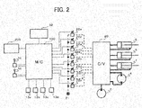
- Fig. 2 is a conceptual diagram showing a configuration of a hydraulic drive system of the construction machine including the one embodiment of the control system for the construction machine according to the present invention.
- devices related to the undercarriage 9 that is of no direct relevance to the embodiments of the present invention will not be shown in Fig. 2 and not explained.
- the hydraulic drive system includes the hydraulic pump device 2, the swing hydraulic motor 4 that is a swing hydraulic actuator, the boom cylinder 5, the arm cylinder 6, and the bucket cylinder 7 that are work implement hydraulic actuators, the right operation lever device 1c, the left operation lever device 1d, the control valve 20, a pilot hydraulic fluid source 21, solenoid proportional valves 22a to 22h, the first to fourth angle sensors 13a to 13d, and a radar device 32.
- the radar device 32 is an approaching object sensor that detects an approaching object near the hydraulic excavator.
- the hydraulic pump device 2 delivers the hydraulic fluid, and supplies the hydraulic fluid to the swing hydraulic motor 4, the boom cylinder 5, the arm cylinder 6, and the bucket cylinder 7 via the control valve 20.
- the control valve 20 includes a directional control valve that serves as a swing control valve that exercises control over the flow rate and the direction of the hydraulic fluid supplied to the swing hydraulic motor 4 that is the swing hydraulic actuator, and directional control valves that serve as work implement control valves each exercising control over the flow rate and the direction of the hydraulic fluid supplied to each of the boom cylinder 5, the arm cylinder 6, the bucket cylinder 7, and the like that are the work implement hydraulic actuators.
- the directional control valves are driven to operate by pilot hydraulic fluids supplied from the corresponding solenoid proportional valves 22a to 22h.
- the solenoid proportional valves 22a to 22h each use the pilot hydraulic fluid supplied from the pilot hydraulic fluid source 21 as a primary pressure, and output a pressure-reduced secondary pilot hydraulic fluid to an operation section of each directional control valve in response to a drive signal from the main controller 100.
- a relationship between the directional control valves and the solenoid proportional valves is defined as follows.
- the boom directional control valve is driven to operate by the pilot hydraulic fluid supplied to the operation section via the boom raising solenoid proportional valve 22c and the boom lowering solenoid proportional valve 22d.
- the arm directional control valve is driven to operate by the pilot hydraulic fluid supplied to the operation section via the arm crowding solenoid proportional valve 22e and the arm dumping solenoid proportional valve 22f.
- the bucket directional control valve is driven to operate by the pilot hydraulic fluid supplied to the operation section via the bucket crowding solenoid proportional valve 22g and the bucket dumping solenoid proportional valve 22h.
- the swing directional control valve is driven to operate by the pilot hydraulic fluid supplied to the operation section via the swing right solenoid proportional valve 22a and the swing left solenoid proportional valve 22b.
- the right operation lever device 1c outputs voltage signals depending on an operation amount and an operation direction of an operation lever to the main controller 100 as a boom operation signal and a bucket operation signal.
- the left operation lever device 1d outputs voltage signals depending on an operation amount and an operation direction of an operation lever to the main controller 100 as a swing operation signal and an arm operation signal.
- the boom and the bucket operation signal transmitted from the right operation lever device 1c, the swing operation signal and the arm transmitted from the left operation lever device 1d, the swing angle, the boom angle, the arm angle, and the bucket angle transmitted from the first to fourth angle sensors 13a to 13d, position information on the approaching object detected near a work region and transmitted from the radar device 32, and a loading target position signal transmitted from an information controller 200 are input to the main controller 100.
- the main controller 100 computes command signals for driving the solenoid proportional valves 22a to 22h in response to these input signals, and output the command signals to the solenoid proportional valves 22a to 22h.
- a method of inputting the loading target position signal set by the information controller 200 may be, for example, a method of inputting a loading position into a dump truck in numeric values as the angles of the hydraulic actuators.
- means of the radar device 32 for acquiring a position of the approaching object may be a camera, a millimeter wave radar, or the like. Computation performed by the information controller 200 and the radar device 32 is not directly relevant to characteristics of the present invention; thus, explanation thereof will be omitted.
- Fig. 3 is a conceptual diagram showing a configuration of the main controller that configures the one embodiment of the control system for the construction machine according to the present invention.
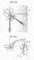
- Fig. 4(a) is a conceptual diagram showing a plan view of the hydraulic excavator including the one embodiment of the control system for the construction machine according to the present invention, and explaining a loading target position, a loading target swing angle, a loading target height, and a lower limit of a work implement height related to computing contents of the main controller.
- Fig. 3 is a conceptual diagram showing a configuration of the main controller that configures the one embodiment of the control system for the construction machine according to the present invention.
- Fig. 4(a) is a conceptual diagram showing a plan view of the hydraulic excavator including the one embodiment of the control system for the construction machine according to the present invention, and explaining a loading target position, a loading target swing angle, a loading target height, and a lower limit of a work implement height related to computing contents of the main controller.
- Fig. 3 is
- 4(b) is a conceptual diagram showing a front view of the hydraulic excavator including the one embodiment of the control system for the construction machine according to the present invention, and explaining the loading target position, the loading target swing angle, the loading target height, and the lower limit of the work implement height related to the computing contents of the main controller.
- the main controller 100 includes a work implement target position setting section 110, a swing stop target angle setting section 120, a work implement target height setting section 130, a swing stoppability determination section 140, a swing control section 150, a work implement control section 160, and an interference avoidance control section 170.
- the work implement target position setting section 110 computes the loading target swing angle and the loading target height on the basis of the loading target position signal transmitted from the information controller 200, outputs a calculated loading target swing angle signal to the swing stop target angle setting section 120 and the work implement target height setting section 130, and outputs a loading target height signal to the work implement target height setting section 130.
- the work implement target position is a target position at which a tip end (bucket 8) of the work implement is disposed.
- the swing stop target angle setting section 120 corrects the loading target swing angle calculated by the work implement target position setting section 110 to compute a swing stop target angle signal, and outputs the calculated swing stop target angle signal to the swing stoppability determination section 140. Details of computation performed by the swing stop target angle setting section 120 will be described later.
- the work implement target height setting section 130 calculates a lower limit value of the work implement height from the loading target swing angle signal and the loading target height signal calculated by the work implement target position setting section 110, computes a work implement target height depending on the swing angle on the basis of the lower limit value of the work implement height, and outputs a calculated work implement target height signal to the work implement control section 160.
- Figs. 4(a) and 4(b) are a plan view and a front view of the hydraulic excavator, respectively.
- a point O denotes an origin of a coordinate system with reference to a front of the undercarriage 9 of the hydraulic excavator, and the point O is at a height equal to that of a boom rotational axis on a swing axis of the hydraulic excavator.
- ⁇ denotes a swing angle that is a relative angle of a front direction of the upper swing structure 10 with respect to a forward movement direction of the undercarriage 9.
- the swing angle ⁇ is the relative angle of the front direction of the upper swing structure 10 with respect to the forward movement direction of the undercarriage 9.
- a point A in Figs. 4(a) and 4(b) denotes the loading target position, which is set to, for example, an upper position of a cargo stand of the dump truck
- ⁇ * in Fig. 4(a) denotes the loading target swing angle
- h* in Fig. 4(b) denotes the loading target height.
- L a length between the points O and A in Fig. 4(a) that is the plan view is indicated by L.
- a plane S1 in Figs. 4(a) and 4(b) denotes the lower limit of the work implement height
- the plane S1 is indicated by a broken line in Fig. 4(b) and indicated by a gradation part in Fig. 4(a) .
- the plane S1 is set in the following procedures. First, in Fig. 4(a) , a plane including the point A, parallel to the swing axis, and crossing a line OA at a right angle is defined as S0.
- the plane S1 generated by inclining the plane S0 at the angle ⁇ with respect to a line at the height h* on the plane S0 that serves as an axis is set as the lower limit of the work implement height.
- the angle ⁇ is preferably set on the basis of a ratio of a swing maximum angular speed ⁇ s max to a boom raising maximum angular speed ⁇ b max in such a manner that the angle ⁇ becomes larger as the swing maximum angular speed is higher.
- the work implement target height is computed as a height of a point C (hr in Fig. 4(b) that is an intersecting point between the plane S1 and a segment lowered from a point B computed using the swing angle ⁇ and the length L to the plane S1 in parallel to the swing axis.
- the work implement target height may be computed using a length between a position of a tip end portion of the bucket 8 or the like computed from the boom angle, the arm angle, and the bucket angle and the swing axis as an alternative to the length L.
- the swing stop target angle signal from the swing stop target angle setting section 120, the swing angle signal from the first angle sensor 13a, the boom angle (elevation angle) signal from the second angle sensor 13b, and the arm angle signal from the third angle sensor 13c are input to the swing stoppability determination section 140.
- the swing stoppability determination section 140 determines whether a swing action can be stopped before an angle of the upper swing structure reaches the swing stop target angle in response to the input signals, computes a swing stop angle margin signal and a swing stop angle deviation signal, and outputs the swing stop angle margin signal and the swing stop angle deviation signal to the swing control section 150 and the work implement control section 160, respectively. Details of computation performed by the swing stoppability determination section 140 will be described later.
- the swing operation signal from the left operation lever device 1d and the swing stop angle margin signal from the swing stoppability determination section 140 are input to the swing control section 150.
- the swing control section 150 computes a swing right drive signal and a swing left drive signal depending on the input signals, corrects the swing right drive signal and the swing left drive signal depending on the swing stop angle margin signal, and outputs the resultant swing right drive signal and the resultant swing left drive signal to drive the swing right solenoid proportional valve 22a and the swing left solenoid proportional valve 22b. Details of computation performed by the swing control section 150 will be described later.
- the boom and the bucket operation signal from the right operation lever device 1c, the arm from the left operation lever device 1d, the work implement target height signal from the work implement target height setting section 130, the swing stop angle deviation signal from the swing stoppability determination section 140, the swing angle signal from the first angle sensor 13a, the boom angle (elevation angle) signal from the second angle sensor 13b, the arm angle signal from the third angle sensor 13c, and the bucket angle signal from the fourth angle sensor 13d are input to the work implement control section 160.
- the work implement control section 160 computes a boom raising drive signal, a boom lowering drive signal, an arm crowding drive signal, an arm dumping drive signal, a bucket crowding drive signal, and a bucket dumping drive signal depending on the input signals, and outputs the boom raising drive signal, the boom lowering drive signal, the arm crowding drive signal, the arm dumping drive signal, the bucket crowding drive signal, and the bucket dumping drive signal to drive the boom raising solenoid proportional valve 22c, the boom lowering solenoid proportional valve 22d, the arm crowding solenoid proportional valve 22e, the arm dumping solenoid proportional valve 22f, the bucket crowding solenoid proportional valve 22g, and the bucket dumping solenoid proportional valve 22h, respectively.
- the work implement control section 160 computes a deviation between the work implement target height signal and the work implement height computed from the boom angle signal, the arm angle signal, and the bucket angle signal as a work implement height deviation signal, and outputs the work implement height deviation signal to the swing stop target angle setting section 120. Details of computation performed by the work implement control section 160 will be described later.
- the position information on the approaching object from the radar device 32, the boom angle signal from the second angle sensor 13b, the arm angle signal from the third angle sensor 13c, and the bucket angle signal from the fourth angle sensor 13d are input to the interference avoidance control section 170.
- the interference avoidance control section 170 computes an emergency stop target angle signal on the basis of the position of the approaching object, and outputs the emergency stop target angle signal to the swing stop target angle setting section 120.
- the main controller 100 may be configured such that height information in the approaching object position information is compared with a height of the work implement computed from the boom angle, the arm angle, and the bucket angle, and output of the emergency stop target angle signal is stopped when the height of the work implement is sufficiently larger.
- the main controller 100 may be configured such that an instruction signal is output to the work implement target height setting section 130 for keeping the work implement target height equal to or larger than the height of the approaching object.
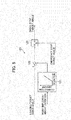
- Fig. 5 is a control block diagram showing an example of computing contents of the swing stop target angle setting section of the main controller that configures the one embodiment of the control system for the construction machine according to the present invention.
- the swing stop target angle setting section 120 computes a swing stop target angle on the basis of the loading target swing angle ⁇ .
- the swing stop target angle setting section 120 includes a function generating element 121, a subtracting element 122, and a selecting element 123.
- the work implement height deviation signal is input to the function generating element 121 from the work implement control section 160.
- the function generating element 121 computes a correction amount signal depending on the work implement height deviation signal by means of a preset map and outputs the correction amount signal to the subtracting element 122.
- the subtracting element 122 subtracts the correction amount signal from the loading target swing angle signal output from the work implement target position setting section 110, computes the swing stop target angle, and outputs the swing stop target angle to the selecting element 123. For example, when the work implement height is smaller than the work implement target height, the deviation signal becomes larger and the correction amount becomes larger as well; thus, the swing stop target angle that is output from the subtracting element 122 becomes smaller. This can avoid the interference of the work implement with the dump truck or the like.
- the swing stop target angle signal from the subtracting element 122 and the emergency stop target angle signal from the interference avoidance control section 170 are input to the selecting element 123.
- the selecting element 123 selects and outputs the swing stop target angle signal from the subtracting element 122.
- the selecting element 123 selects and outputs this signal. Since this computation sets the swing stop target angle depending on the position of the approaching object, it is possible to avoid the interference of the work implement 15 with the approaching object.
- Fig. 6 is a control block diagram showing an example of computing contents of the swing stoppability determination section of the main controller that configures the one embodiment of the control system for the construction machine according to the present invention.
- the swing stoppability determination section 140 determines whether the swing action can be stopped before the angle of the upper swing structure reaches the swing stop target angle on the basis of the swing stop target angle and the swing angle, and computes the swing stop angle margin signal and the swing stop angle deviation signal.
- the swing stoppability determination section 140 includes a differentiating element 1401, a computing element 1402, a first adding element 1403, a second adding element 1404, a first trigonometric function computing element 1405, a second trigonometric function computing element 1406, a function generating element 1407, a first subtracting element 1408, a sign function computing element 1409, a multiplying element 1410, a second subtracting element 1411, a first extraction computing element 1412, and a second extraction computing element 1413.
- the swing angle signal from the first angle sensor 13a is input to the differentiating element 1401.
- the differentiating element 1401 calculates a swing angular speed signal by performing differential computation, and outputs the swing angular speed signal to the computing element 1402 and the sign function computing element 1409.
- the boom angle signal from the second angle sensor 13b and the arm angle signal from the third angle sensor 13c are input to the first adding element 1403.
- the first adding element 1403 outputs a signal obtained by addition computation to the second trigonometric function computing element 1406.
- the boom angle signal from the second angle sensor 13b is input to the first trigonometric function computing element 1405.
- the first trigonometric function computing element 1405 computes an extension amount of the boom by performing trigonometric function computation, and outputs the extension amount to the second adding element 1404.
- the addition signal by adding up the boom angle signal and the arm angle signal from the first adding element 1403 is input to the second trigonometric function computing element 1406.
- the second trigonometric function computing element 1406 computes an extension amount solely of the arm by performing trigonometric function computation, and outputs the extension amount to the second adding element 1404.
- An extension amount signal of the boom and an extension amount signal solely of the arm are input to the second adding element 1404.
- the second adding element 1404 performs addition computation and outputs an arm extension amount signal to the function generating element 1407.
- the arm extension amount signal is input to the function generating element 1407 from the second adding element 1404.
- the function generating element 1407 estimates and computes a inertia moment signal J depending on the arm extension amount signal by means of a preset map, and outputs the inertia moment signal J to the computing element 1402.
- the swing angular speed signal from the differentiating element 1401 and the inertia moment signal from the function generating element 1407 are input to the computing element 1402.
- the computing element 1402 computes a swing smallest stop angle signal A using the following Equation (2) and outputs the swing smallest stop angle signal A to the second subtracting element 1411. It is noted that the swing smallest stop angle signal A is a minimum value of an increment of the swing stop angle by the inertia.
- A J ⁇ 2 / 2 T max
- Equation (2) ⁇ denotes the swing angular speed signal from the differentiating element 1401
- T max denotes a maximum value of a torque that can be output by the swing hydraulic motor 4 and is set on the basis of a volume, a relief pressure, and the like of the swing hydraulic motor 4.
- J denotes the swing inertia moment signal from the function generating element 1407.
- the swing stop target angle signal from the swing stop target angle setting section 120 and the swing angle signal from the first angle sensor 13a are input to the first subtracting element 1408.
- the first subtracting element 1408 computes a deviation and outputs the deviation to the multiplying element 1410.
- the swing angular speed signal from the differentiating element 1401 is input to the sign function computing element 1409.
- the sign function computing element 1409 computes a sign (+ or -) of the input signal and outputs the sign to the multiplying element 1410.
- a deviation signal from the first subtracting element 1408 and a sign signal from the sign function computing element 1409 are input to the multiplying element 1410.
- the multiplying element 1410 performs multiplication of the input signals, thereby calculating a relative value signal of the swing stop target angle to a current swing angle.
- the calculated relative value signal of the swing stop target angle to the current swing angle is output to the second subtracting element 1411.
- the swing smallest stop angle signal from the computing element 1402 and the relative value signal of the swing stop target angle to the current swing angle from the multiplying element 1410 are input to the second subtracting element 1411.
- the second subtracting element 1411 computes a deviation between the swing smallest stop angle signal and the relative value signal and outputs the deviation to the first extraction computing element 1412 and the second extraction computing element 1413.
- a deviation signal from the second subtracting element 1411 is input to the first extraction computing element 1412.
- the first extraction computing element 1412 computes an absolute value of the input signal and outputs the absolute value.
- a case in which the deviation signal from the second subtracting element 1411 is the negative value refers to a case in which the swing smallest stop angle signal is smaller than the relative value signal of the swing stop target angle to the current swing stop angle.
- the first extraction computing element 1412 determines that swing of the upper swing structure 10 can be stopped before the angle of the upper swing structure 10 reaches the swing stop target angle, extracts the absolute value of the negative value that is the deviation signal as the swing stop angle margin signal, and outputs the swing stop angle margin signal to the swing control section 150.
- the deviation signal from the second subtracting element 1411 is input to the second extraction computing element 1413.
- the second extraction computing element 1413 computes an absolute value of the input signal and outputs the absolute value.
- a case in which the deviation signal from the second subtracting element 1411 is the positive value refers to a case in which the swing smallest stop angle signal is larger than the relative value signal of the swing stop target angle to the current swing angle.
- the second extraction computing element 1413 determines that the swing of the upper swing structure 10 cannot be stopped before the angle of the upper swing structure 10 reaches the swing stop target angle, extracts the positive value that is the deviation signal as the swing stop angle deviation signal, and outputs the swing stop angle deviation signal to the work implement control section 160.
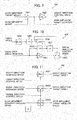
- Fig. 7 is a control block diagram showing an example of computing contents of the swing control section of the main controller that configures the one embodiment of the control system for the construction machine according to the present invention.
- the swing control section 150 computes the swing right drive signal and the swing left drive signal depending on the swing operation signal and the swing stop angle margin signal.
- the swing control section 150 includes a first function generating element 151, a second function generating element 152, a third function generating element 153, a first limiting element 154, and a second limiting element 155.
- the swing operation signal from the left operation lever device 1d is input to the first function generating element 151.
- the first function generating element 151 computes the swing right drive signal depending on the swing operation signal by means of a preset drive signal map, and outputs the swing right drive signal to the first limiting element 154.
- the swing operation signal from the left operation lever device 1d is input to the second function generating element 152.
- the second function generating element 152 computes the swing left drive signal depending on the swing operation signal by means of a preset drive signal map, and outputs the swing left drive signal to the second limiting element 155.
- the swing stop angle margin signal from the swing stoppability determination section 140 is input to the third function generating element 153.
- the third function generating element 153 computes a swing drive signal upper limit signal depending on the swing stop angle margin signal by means of a preset signal upper limit map, and outputs the swing drive signal upper limit signal to the first and second limiting elements 154 and 155.
- the swing right drive signal from the first function generating element 151 and the swing drive signal upper limit signal from the third function generating element 153 are input to the first limiting element 154.
- the first limiting element 154 outputs the swing right drive signal limited to be equal to or smaller than the swing drive signal upper limit signal.
- the swing left drive signal from the second function generating element 152 and the swing drive signal upper limit signal from the third function generating element 153 are input to the second limiting element 155.
- the second limiting element 155 outputs the swing left drive signal limited to be equal to or smaller than the swing drive signal upper limit signal.
- the signal upper limit map of the third function generating element 153 is set such that a swing drive signal upper limit becomes larger as the swing stop angle margin signal is larger in a positive direction. Owing to this, when the swing stop angle margin signal is large, the swing right drive signal and the swing left drive signal are output without being limited. As the swing stop angle margin signal is smaller, then the swing right drive signal and the swing left drive signal are limited to be smaller, and a speed of the swing is reduced.
- Fig. 8 is conceptual diagram showing a configuration of the work implement control section of the main controller that configures the one embodiment of the control system for the construction machine according to the present invention.
- the work implement control section 160 of the main controller 100 includes a demanded speed computing section 161, a speed kinematic coordinate transformation section 162, a position kinematic coordinate transformation section 163, a height direction control speed computing section 164, a radial direction control speed computing section 165, a target speed computing section 166, a speed inverse kinematic coordinate transformation section 167, and a solenoid valve drive signal control section 168.
- the boom and the bucket operation signal from the right operation lever device 1c and the arm from the left operation lever device 1d are input to the demanded speed computing section 161.
- the demanded speed computing section 161 computes a boom demanded speed signal, an arm demanded speed signal, and a bucket demanded speed signal as demanded speeds to the boom cylinder 5, the arm cylinder 6, and the bucket cylinder 7, respectively, and outputs the boom demanded speed signal, the arm demanded speed signal, and the bucket demanded speed signal to the speed kinematic coordinate transformation section 162.
- the boom angle signal from the second angle sensor 13b, the arm angle signal from the third angle sensor 13c, and the bucket angle signal from the fourth angle sensor 13d as well as the demanded speed signals described above are input to the speed kinematic coordinate transformation section 162.
- the speed kinematic coordinate transformation section 162 computes a work implement radial direction demanded speed signal, a work implement height direction demanded speed signal, and a work implement demanded angular speed signal from the demanded speed signals by performing well-known kinematic coordinate transformation based on the angle signals, and outputs the work implement radial direction demanded speed signal, the height direction demanded speed signal, and the work implement demanded angular speed signal to the target speed computing section 166.
- the boom angle signal from the second angle sensor 13b, the arm angle signal from the third angle sensor 13c, and the bucket angle signal from the fourth angle sensor 13d are input to the position kinematic coordinate transformation section 163.
- the position kinematic coordinate transformation section 163 computes a work implement height signal by performing well-known kinematic coordinate transformation, and outputs the work implement height signal to the height direction control speed computing section 164.
- the work implement target height signal from the work implement target height setting section 130 as well as the work implement height signal is input to the height direction control speed computing section 164.
- the height direction control speed computing section 164 computes a height direction control speed signal and the work implement height deviation signal on the basis of the input signals, outputs the height direction control speed signal to the target speed computing section 166, and outputs the work implement height deviation signal to the swing stop target angle setting section 120. Details of computation performed by the height direction control speed computing section 164 will be described later.
- the swing stop angle deviation signal from the swing stoppability determination section 140 and the swing angle signal from the first angle sensor 13a are input to the radial direction control speed computing section 165.
- the radial direction control speed computing section 165 computes a radial direction control speed signal on the basis of the input signals, and outputs the radial direction control speed signal to the target speed computing section 166. Details of computation performed by the radial direction control speed computing section 165 will be described later.
- the work implement radial direction demanded speed signal, the height direction demanded speed signal, and the work implement demanded angular speed signal from the speed kinematic coordinate transformation section 162, the height direction control speed signal from the height direction control speed computing section 164, and the radial direction control speed signal from the radial direction control speed computing section 165 are input to the target speed computing section 166.
- the target speed computing section 166 computes a radial direction target speed signal, a height direction target speed signal, and a work implement target angular speed signal on the basis of the input signals, and outputs the radial direction target speed signal, the height direction target speed signal, and the work implement target angular speed to the speed inverse kinematic coordinate transformation section 167. Details of computation performed by the target speed computing section 166 will be described later.
- the boom angle signal from the second angle sensor 13b, the arm angle signal from the third angle sensor 13c, and the bucket angle signal from the fourth angle sensor 13d as well as the target speed signals (and the target angular speed) described above are input to the speed inverse kinematic coordinate transformation section 167.
- the speed inverse kinematic coordinate transformation section 167 computes a boom target speed signal, an arm target speed signal, and a bucket target speed signal from the radial direction target speed signal, the height direction target speed signal, and the work implement target angular speed by performing well-known inverse kinematic coordinate transformation based on the angle signals, and outputs the boom target speed signal, the arm target speed signal, and the bucket target speed signal to the solenoid valve drive signal control section 168.
- the solenoid valve drive signal control section 168 generates the boom raising drive signal, the boom lowering drive signal, the arm crowding drive signal, the arm dumping drive signal, the bucket crowding drive signal, and the bucket dumping drive signal depending on a boom target speed, an arm target speed, and a bucket target speed.
- Fig. 9 is a control block diagram showing an example of computing contents of the height direction control speed computing section of the main controller that configures the one embodiment of the control system for the construction machine according to the present invention.
- the height direction control speed computing section 164 computes a work implement height deviation and the like on the basis of the work implement target height signal and the work implement height signal.
- the height direction control speed computing section 164 includes a subtracting element 1641 and a multiplying element 1642.
- the work implement target height signal from the work implement target height setting section 130 and the work implement height signal from the position kinematic coordinate transformation section 163 are input to the subtracting element 1641.
- the subtracting element 1641 computes the deviation signal and outputs the deviation signal to the multiplying element 1642 and the swing stop target angle setting section 120.
- the multiplying element 1642 multiplies the deviation signal that is the input signal by a gain Kh to compute the height direction control speed signal, and outputs the height direction control speed signal to the target speed computing section 166.
- the gain Kh is a well-known P gain for feedback control and set such that the height direction control speed signal becomes larger in a direction in which the work implement is raised as the work implement height deviation signal is larger.
- Fig. 10 is a control block diagram showing an example of computing contents of the radial direction control speed computing section of the main controller that configures the one embodiment of the control system for the construction machine according to the present invention.
- the radial direction control speed computing section 165 multiplies the swing stop angle deviation signal by a gain Kr to compute the radial direction control speed signal, and outputs the radial direction control speed signal to the target speed computing section 166 when a predetermined condition is satisfied.
- the radial direction control speed computing section 165 includes a multiplying element 1651, a first determination element 1652, a conditional connecting element 1653, a differentiating element 1654, a second determination element 1655, an AND computing element 1656, and an OR computing element 1657.
- the swing stop angle deviation signal from the swing stoppability determination section 140 is input to the multiplying element 1651.
- the multiplying element 1651 multiplies the swing stop angle deviation signal by the gain Kr to compute the radial direction control speed signal, and outputs the radial direction control speed signal to the conditional connecting element 1653.
- the swing stop angle deviation signal is input to the first determination element 1652.
- the first determination element 1652 outputs a logical signal 1 to the OR computing element 1657 when determining that the input signal is a positive value.
- An output from the AND computing element 1656 and an output from the first determination element 1652 are input to the OR computing element 1657.
- the OR computing element 1657 outputs an OR signal to the conditional connecting element 1653 and the AND computing element 1656.
- the radial direction control speed signal from the multiplying element 1651 and the OR signal from the OR computing element 1657 are input to the conditional connecting element 1653.
- the OR signal is 1
- the conditional connecting element 1653 enables connection between the conditional connecting element 1653 and the multiplying element 1651 element and validly outputs the radial direction control speed signal to the target speed computing section 166.
- the conditional connecting element 1653 disables the connection and outputs an invalid value to the target speed computing section 166.
- the gain Kr of the multiplying element 1651 is a well-known P gain for the feedback control, and is set such that the multiplying element 1651 computes the radial direction control speed in a direction in which the work implement is made closer to the swing axis as the swing stop angle deviation is larger to cause the work implement to execute a contraction action.
- the swing angle signal from the first angle sensor 13a is input to the differentiating element 1654.
- the differentiating element 1654 calculates the swing angular speed signal by performing differential computation and outputs the swing angular speed signal to the second determination element 1655.
- the second determination element 1655 When determining that the input swing angular speed signal is not generally zero, the second determination element 1655 outputs a logical signal 1 to the AND computing element 1656.
- the AND computing element 1656 outputs an AND signal obtained by AND between the logical signal from the OR computing element 1657 and the logical signal from the second determination element 1655 to the OR computing element 1657.
- This circuit operates in such a manner that even when the second determination element 1655 determines that the swing angular speed signal is not generally zero and it is determined that the swing stop angle deviation is the positive value, the connection between the conditional connecting element 1653 and the multiplying element 1651 is enabled and the radial direction control speed signal is validly output.
- the radial direction control speed signal is set to zero and output until the swing is stopped (the swing angular speed signal becomes generally zero). It is, therefore, possible to prohibit the work implement from executing an extension action in a direction in which the swing moment of inertia increases.
- Fig. 11 is a control block diagram showing an example of computing contents of the target speed computing section of the main controller that configures the one embodiment of the control system for the construction machine according to the present invention.
- the target speed computing section 166 includes a maximum value selecting element 1661, a selecting element 1662, and a conditional switch element 1663.
- the height direction demanded speed signal from the speed kinematic coordinate transformation section 162 and the height direction control speed signal from the height direction control speed computing section 164 are input to the maximum value selecting element 1661.
- the maximum value selecting element 1661 selects the larger signal out of the two speed signals, and outputs the selected signal to the speed inverse kinematic coordinate transformation section 167 as the height direction target speed signal.
- the radial direction demanded speed signal from the speed kinematic coordinate transformation section 162 and the radial direction control speed signal from the radial direction control speed computing section 165 are input to the selecting element 1662.
- the selecting element 1662 selects the radial direction demanded speed signal.
- the selecting element 1662 selects the radial direction control speed signal and outputs the radial direction control speed signal to the speed inverse kinematic coordinate transformation section 167 as the radial direction target speed signal.
- the work implement demanded angular speed signal from the speed kinematic coordinate transformation section 162 and the radial direction control speed signal from the radial direction control speed computing section 165 are input to the conditional switch element 1663.
- the conditional switch element 1663 When the radial direction control speed signal is not input, the conditional switch element 1663 outputs the work implement demanded angular speed signal to the speed inverse kinematic coordinate transformation section 167 as the work implement target angular speed.
- the conditional switch element 1663 When the radial direction control speed signal is input, the conditional switch element 1663 outputs a zero signal to the speed inverse kinematic coordinate transformation section 167 as the work implement target angular speed.
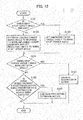
- Fig. 12 is a flowchart showing an example of a computing flow of the main controller that configures the one embodiment of the control system for the construction machine according to the present invention.
- the main controller 100 determines whether the emergency stop target angle is present (Step S121). Specifically, the main controller 100 determines whether the interference avoidance control section 170 receives the position information on the approaching object from the radar device 32 and outputs the emergency stop target angle signal to the swing stop target angle setting section 120. When the emergency stop target angle is present, processing goes to (Step S122); otherwise, the processing goes to (Step S123).
- the main controller 100 sets the emergency stop target angle to the swing stop target angle (Step S122). Specifically, the swing stop target angle setting section 120 sets the emergency stop target angle signal from the interference avoidance control section 170 to the swing stop target angle. The swing stop target angle depending on the position of the approaching object is thereby set when the approaching object is detected; thus, it is possible to avoid the interference between the work implement and the approaching object.
- the main controller 100 corrects the loading target swing angle depending on the work implement height deviation and sets the resultant angle to the swing stop target angle (Step S123).
- the swing stop target angle setting section 120 computes the correction amount signal depending on the work implement height deviation signal and subtracts the correction amount from the loading target swing angle. For example, when the work implement height is smaller than the work implement target height, the deviation signal becomes larger and the correction amount becomes larger as well; thus, the swing stop target angle becomes smaller. This can avoid the interference of the work implement with the dump truck or the like.
- the main controller 100 determines whether the swing stop target angle is smaller than the swing smallest stop angle (Step S141). Specifically, the swing stoppability determination section 140 computes the deviation between the relative value of the swing stop target angle to the swing angle and the swing smallest stop angle, and determines that the swing smallest stop angle is larger when this deviation is the positive value. When the swing stop target angle is smaller than the swing smallest stop angle, the processing goes to (Step S161); otherwise, the processing goes to (Step S162).
- the main controller 100 controls the work implement to execute a contraction action (Step S161). Specifically, the swing stoppability determination section 140 determines that the swing cannot be stopped before the angle of the upper swing structure 10 reaches the swing stop target angle, and outputs the positive value that is the deviation described above to the work implement control section 160 as the swing stop deviation signal.
- the work implement control section 160 computes the radial direction control speed in the direction in which the work implement is made closer to the swing axis on the basis of this swing stop deviation signal. The work implement thereby executes the contraction action. As a result, the swing moment of inertia decreases and it is possible to stop the upper swing structure at the desired swing stop angle.
- the main controller 100 determines whether the swing speed is present and either whether the extension action of the work implement is being prohibited or the contraction action is being executed by the work implement (Step S162). Specifically, there is provided a so-called self-holding circuit that outputs the radial direction control speed signal even when the radial direction control speed computing section 165 of the work implement control section 160 computes the swing angular speed from the swing angle, determines that the swing angular speed is not generally zero, and determines that the swing stop angle deviation is the positive value using the logical computing elements.
- the processing goes to (Step S163); otherwise, the processing goes to END to end the processing.
- the main controller 100 prohibits the work implement from executing the extension action (Step S163). Specifically, even when the swing stop angle deviation becomes zero after the radial direction control speed computing section 165 of the work implement control section 160 determines once that the swing stop angle deviation is the positive value, the self-holding circuit described above continues to set the radial direction control speed to zero until the swing is stopped, thereby prohibiting the work implement from executing the extension action. It is thereby possible to prevent the swing moment of inertia from increasing and stop the upper swing structure at the desired swing stop angle.
- Step S161 After execution of the processing in (Step S161) or (Step S163), the processing goes to END to end the processing.
- the one embodiment of the control system for the construction machine of the present invention includes the swing stoppability determination section 140 that determines whether the swing can be stopped, and the work implement control section 160 that either prohibits the work implement from executing the extension action in a swing radial direction or allows the work implement to execute the contraction action in the swing radial direction in response to the signal indicating whether the swing can be stopped. Therefore, it is possible to suppress the increase of the swing inertia and reduce the swing inertia. It is thereby possible to stop the upper swing structure 10 at the desired swing stop angle.
- the sections that detects the angles thereof are not limited to the angle sensors.
- the control system for the construction machine may be configured such that the boom cylinder 5, the arm cylinder 6, and the bucket cylinder 7 include stroke sensors that detect strokes of cylinder rods, and such that the angles of the boom 11, the arm 12, and the bucket 8 are calculated on the basis of the strokes of the cylinder rods, respectively.
- the present invention is not limited to the embodiment described above but encompasses various modifications.
- the present invention has been explained while the hydraulic excavator is taken by way of example in the above embodiment; however, the present invention is not limited to the hydraulic excavator.
- the present invention is also applicable to a crane or the like if the crane or the like includes a swing structure and a work implement.
Description
- The present invention relates to a control system for a construction machine.
- Generally, when conducting work for loading excavated objects into a dump truck using a hydraulic excavator that is a construction machine, then an operator causes a work implement to execute a boom raising action while controlling an upper swing structure to rotate or swing by operator's simultaneous adjustment of a swing angle and a height of the work implement using operation devices, and moves the work implement from an excavation position to an upper position of a cargo stand of the dump truck to discharge the excavated objects.
- The upper swing structure continues swinging through inertia even after the operator stops a swing operation, and a swing stop angle varies depending on a swing speed and swing inertia at the time of stopping the swing operation. For this reason, it is necessary to determine stop timing of the swing operation in the light of an increase of the swing stop angle by the inertia for stopping the upper swing structure at a desired swing angle. In this way, when performing a combined operation involving the swing action or the swing stop operation for stopping the upper swing structure at a desired position, the operator is required to operate the hydraulic excavator with a higher degree of concentration. In addition, operator's monitoring awareness of surroundings is diminished because of the concentration of awareness on operating the hydraulic excavator. For example, when an approaching object to a swing range of the work implement is present, the discovery of the approaching object is possibly delayed.
- There are known a construction machine swing control system and a method thereof that can stop an upper swing structure in a predetermined range even if an operator stops a swing operation for which the operator is required to have a high degree of concentration as described above at different timing (refer to, for example, Patent Document 1). According to the construction machine swing control system and the method thereof, an optimum swing-operation-stop starting position for stopping the upper swing structure in the predetermined range is estimated, a stop target position is calculated using a current swing position and the stop starting position, and a swing motor is then controlled such that the upper swing structure is stopped at the stop target position. It is thereby possible to stop the swing of the upper swing structure in the predetermined range even if the operator stops the swing operation at the different timing.
- There are also known a swing work machine and a swing work machine control method for detecting an approaching object described above to a swing range of the work implement and stopping the swing (refer to, for example, Patent Document 2). According to the swing work machine and the swing work machine control method, it is determined whether there is a probability of interference between the swing work machine and the approaching object on the basis of a current swing speed, current swing inertia, and a position of the approaching object, and a swing action is controlled.
- Furthermore, Patent Document 3 discloses a swing type backhoe comprising a controller for automatically stopping the swing structure either in the left or right set stop position and in which the controller includes a mode setting section for setting a swing automatic stop mode comprising a function of a swing speed and a swing angle at the time of deceleration of the swing structure and in order to automatically stop the swing structure at the set stop position, wherein the swing type backhoe comprises sensor means for sensing the angle of the arm relative to the boom and mode instruction means for automatically selecting the swing automatic stop mode in accordance with the angle of the arm relative to the boom based on information from the sensor means thereby to instruct the selected swing automatic stop mode to the mode setting section.
-
- Patent Document 1:
JP-2013-535593-T - Patent Document 2:
JP-2012-021290-A - Patent Document 3:
WO 2014/123 253 A1 - A technique of
Patent Document 1 calculates the stop target position using the current swing position and the stop starting position. Furthermore, a technique ofPatent Document 2 determines the probability of the interference with the approaching object on the basis of the current swing speed, the current swing inertia, and the position of the approaching object. Owing to this, changes (of the swing inertia and the swing stop target position) that occur after, for example, the stop of the swing operation is started are not possibly, sufficiently considered. - For example, when an arm extending action is executed in a state in which the operator performs the swing stop operation but the upper swing structure is not completely stopped yet, the swing inertia increases from that at timing of the stop operation. However, the techniques of
Patent Documents - Furthermore, at the time of loading the excavated objects into the dump truck, a boom raising action is executed while causing the upper swing structure to swing, and the work implement is moved from the excavation position to the upper position of the cargo stand of the dump truck. However, when the boom raising action is delayed, a contact possibly occurs between the cargo stand of the dump truck and the work implement. For avoidance of this contact, it is necessary to stop the swing of the upper swing structure earlier than the start to stop the swing operation. It is also necessary to stop the swing of the upper swing structure earlier than arrival at a predetermined stop position when the approaching object approaches a machine body after the approaching object is detected during swing work and the operator stops the swing operation. In such a case, a speed reduction torque exceeding a maximum value of a torque that can be output by a swing motor, with the result that the operator is unable to stop the swing of the upper swing structure at the desired swing stop angle.
- The present invention has been achieved on the basis of the circumstances described above, and an object of the present invention is to provide a control system for a construction machine that can stop an upper swing structure at a desired swing stop angle.
- According to the invention there is provided a construction machine comprising: an undercarriage; an upper swing structure rotatably mounted to swing on the undercarriage; a work implement attached to the upper swing structure to be able to rotate vertically thereto ; a swing hydraulic actuator that drives the upper swing structure to swing; work implement hydraulic actuators that drive the work implement; a hydraulic pump; work implement control valves and a swing control valve configured to exercise control of flow rates and directions of hydraulic fluids supplied from the hydraulic pump to the work implement hydraulic actuators and the swing hydraulic actuator; work implement operation devices and a swing operation device configured to instruct the work implement and the upper swing structure to be actuated; and a control system comprising a main controller configured to output drive signals to the work implement control valves and the swing control valve on the basis of instruction signals from the work implement operation devices and the swing operation device, wherein the control system further comprises: a first angle sensor configured to detect a swing angle of the upper swing structure with respect to the undercarriage; and a second angle sensor configured to detect an elevation angle of the work implement with respect to the upper swing structure, and the main controller comprises: a swing stop target angle setting section configured to set a swing stop target angle of the upper swing structure; a swing control section configured to calculate the drive signal on the basis of a difference between the swing angle of the upper swing structure detected by the first angle sensor and the swing stop target angle set by the swing stop target angle setting section and the instruction signal from the swing operation device, and to output the drive signal to the swing control valve; a swing stoppability determination section configured to determine whether a swing action can be stopped before an angle of the upper swing structure reaches the swing stop target angle on the basis of the swing angle of the upper swing structure detected by the first angle sensor, the swing stop target angle set by the swing stop target angle setting section, and the elevation angle of the work implement detected by the second angle sensor; and a work implement control section configured to output a drive signal to the work implement control valve in such a manner that when a determination result of the swing stoppability determination section is No, an action of the work implement in a direction in which at least a swing moment of inertia increases is limited or prohibited.
- According to the present invention, the control system for a construction machine includes the swing stoppability determination section that determines whether the swing can be stopped, and the work implement control section that either prohibits the work implement from executing the extension action in a swing radial direction or allows the work implement to execute the contraction action in the swing radial direction in response to the signal indicating whether the swing can be stopped. Therefore, it is possible to suppress the increase of the swing inertia and reduce the swing inertia. It is thereby possible to stop the upper swing structure at the desired swing stop angle.
-
-
Fig. 1 is a perspective view showing a hydraulic excavator including one embodiment of a control system for a construction machine according to the present invention. -
Fig. 2 is a conceptual diagram showing a configuration of a hydraulic drive system of a construction machine including the one embodiment of the control system for the construction machine according to the present invention. -
Fig. 3 is a conceptual diagram showing a configuration of a main controller that configures the one embodiment of the control system for the construction machine according to the present invention. -
Fig. 4(a) is a conceptual diagram showing a plan view of the hydraulic excavator including the one embodiment of the control system for the construction machine according to the present invention, and explaining a loading target position, a loading target swing angle, a loading target height, and a lower limit of a work implement height related to computing contents of the main controller. -
Fig. 4(b) is a conceptual diagram showing a front view of the hydraulic excavator including the one embodiment of the control system for the construction machine according to the present invention, and explaining the loading target position, the loading target swing angle, the loading target height, and the lower limit of the work implement height related to the computing contents of the main controller. -
Fig. 5 is a control block diagram showing an example of computing contents of a swing stop target angle setting section of the main controller that configures the one embodiment of the control system for the construction machine according to the present invention. -
Fig. 6 is a control block diagram showing an example of computing contents of a swing stoppability determination section of the main controller that configures the one embodiment of the control system for the construction machine according to the present invention. -
Fig. 7 is a control block diagram showing an example of computing contents of a swing control section of the main controller that configures the one embodiment of the control system for the construction machine according to the present invention. -
Fig. 8 is a conceptual diagram showing a configuration of a work implement control section of the main controller that configures the one embodiment of the control system for the construction machine according to the present invention. -
Fig. 9 is a control block diagram showing an example of computing contents of a height direction control speed computing section of the main controller that configures the one embodiment of the control system for the construction machine according to the present invention. -
Fig. 10 is a control block diagram showing an example of computing contents of a radial direction control speed computing section of the main controller that configures the one embodiment of the control system for the construction machine according to the present invention. -
Fig. 11 is a control block diagram showing an example of computing contents of a target speed computing section of the main controller that configures the one embodiment of the control system for the construction machine according to the present invention. -
Fig. 12 is a flowchart showing an example of a computing flow of the main controller that configures the one embodiment of the control system for the construction machine according to the present invention. - Embodiments of a control system for a construction machine according to the present invention will be explained hereinafter with reference to the drawings.
-
Fig. 1 is a perspective view showing a hydraulic excavator including one embodiment of the control system for the construction machine according to the present invention. As shown inFig. 1 , the hydraulic excavator includes anundercarriage 9, anupper swing structure 10, and a work implement 15. Theundercarriage 9 has left and right crawler belt travel devices, which are driven by left and right travelhydraulic motors 3b and 3a (only the left travelhydraulic motor 3b is shown). Theupper swing structure 10 is rotatably mounted on theundercarriage 9 and driven to swing by a swinghydraulic motor 4. Theupper swing structure 10 includes anengine 14 that serves as a prime mover and ahydraulic pump device 2 driven by theengine 14. - The
work implement 15 is attached to a front portion of theupper swing structure 10 in such a manner as to be able to be rotate vertically or elevated. Theupper swing structure 10 is provided with an operation room, and operation devices such as a travel right operation lever device 1a, a travel leftoperation lever device 1b, and a right operation lever device 1c and a leftoperation lever device 1d for instructing the work implement 15 in actions and a swing action are disposed in the operation room. - The work implement 15 has a multijoint structure having a
boom 11, anarm 12, and a bucket 8. Theboom 11 rotates vertically with respect to theupper swing structure 10 by extension/contraction of aboom cylinder 5, thearm 12 rotates vertically and longitudinally with respect to theboom 11 by extension/contraction of an arm cylinder 6, and the bucket 8 rotates vertically and longitudinally with respect to thearm 12 by extension/contraction of abucket cylinder 7. - Furthermore, the
work implement 15 includes: for calculating a position of the work implement 15, afirst angle sensor 13a that is provided near a coupling portion between theundercarriage 9 and theupper swing structure 10 and that detects a swing angle of theupper swing structure 10 with respect to theundercarriage 9; asecond angle sensor 13b that is provided near a coupling portion between theupper swing structure 10 and theboom 11 and that detects an angle (elevation angle) of theboom 11 with respect to a horizontal surface; athird angle sensor 13c that is provided near a coupling portion between theboom 11 and thearm 12 and that detects an angle of thearm 12; and afourth angle sensor 13d that is provided near a coupling portion between thearm 12 and the bucket 8 and that detects an angle of the bucket 8. Angle signals detected by these first tofourth angle sensors 13a to 13d are input to amain controller 100 to be described later. - A
control valve 20 exercises control over a flow (a flow rate and a direction) of a hydraulic fluid supplied from thehydraulic pump device 2 to each of hydraulic actuators including theboom cylinder 5, the arm cylinder 6, thebucket cylinder 7, and the left and right travelhydraulic motors 3b and 3a described above. -
Fig. 2 is a conceptual diagram showing a configuration of a hydraulic drive system of the construction machine including the one embodiment of the control system for the construction machine according to the present invention. For brevity of explanation, devices related to theundercarriage 9 that is of no direct relevance to the embodiments of the present invention will not be shown inFig. 2 and not explained. - In
Fig. 2 , the hydraulic drive system includes thehydraulic pump device 2, the swinghydraulic motor 4 that is a swing hydraulic actuator, theboom cylinder 5, the arm cylinder 6, and thebucket cylinder 7 that are work implement hydraulic actuators, the right operation lever device 1c, the leftoperation lever device 1d, thecontrol valve 20, a pilot hydraulicfluid source 21, solenoidproportional valves 22a to 22h, the first tofourth angle sensors 13a to 13d, and aradar device 32. It is noted that theradar device 32 is an approaching object sensor that detects an approaching object near the hydraulic excavator. - The
hydraulic pump device 2 delivers the hydraulic fluid, and supplies the hydraulic fluid to the swinghydraulic motor 4, theboom cylinder 5, the arm cylinder 6, and thebucket cylinder 7 via thecontrol valve 20. - The
control valve 20 includes a directional control valve that serves as a swing control valve that exercises control over the flow rate and the direction of the hydraulic fluid supplied to the swinghydraulic motor 4 that is the swing hydraulic actuator, and directional control valves that serve as work implement control valves each exercising control over the flow rate and the direction of the hydraulic fluid supplied to each of theboom cylinder 5, the arm cylinder 6, thebucket cylinder 7, and the like that are the work implement hydraulic actuators. The directional control valves are driven to operate by pilot hydraulic fluids supplied from the corresponding solenoidproportional valves 22a to 22h. - The solenoid
proportional valves 22a to 22h each use the pilot hydraulic fluid supplied from the pilot hydraulicfluid source 21 as a primary pressure, and output a pressure-reduced secondary pilot hydraulic fluid to an operation section of each directional control valve in response to a drive signal from themain controller 100. A relationship between the directional control valves and the solenoid proportional valves is defined as follows. The boom directional control valve is driven to operate by the pilot hydraulic fluid supplied to the operation section via the boom raising solenoidproportional valve 22c and the boom lowering solenoid proportional valve 22d. The arm directional control valve is driven to operate by the pilot hydraulic fluid supplied to the operation section via the arm crowding solenoid proportional valve 22e and the arm dumping solenoid proportional valve 22f. The bucket directional control valve is driven to operate by the pilot hydraulic fluid supplied to the operation section via the bucket crowding solenoid proportional valve 22g and the bucket dumping solenoidproportional valve 22h. The swing directional control valve is driven to operate by the pilot hydraulic fluid supplied to the operation section via the swing right solenoidproportional valve 22a and the swing left solenoidproportional valve 22b. - The right operation lever device 1c outputs voltage signals depending on an operation amount and an operation direction of an operation lever to the
main controller 100 as a boom operation signal and a bucket operation signal. Likewise, the leftoperation lever device 1d outputs voltage signals depending on an operation amount and an operation direction of an operation lever to themain controller 100 as a swing operation signal and an arm operation signal. - The boom and the bucket operation signal transmitted from the right operation lever device 1c, the swing operation signal and the arm transmitted from the left
operation lever device 1d, the swing angle, the boom angle, the arm angle, and the bucket angle transmitted from the first tofourth angle sensors 13a to 13d, position information on the approaching object detected near a work region and transmitted from theradar device 32, and a loading target position signal transmitted from aninformation controller 200 are input to themain controller 100. Themain controller 100 computes command signals for driving the solenoidproportional valves 22a to 22h in response to these input signals, and output the command signals to the solenoidproportional valves 22a to 22h. - It is noted that a method of inputting the loading target position signal set by the
information controller 200 may be, for example, a method of inputting a loading position into a dump truck in numeric values as the angles of the hydraulic actuators. In addition, means of theradar device 32 for acquiring a position of the approaching object may be a camera, a millimeter wave radar, or the like. Computation performed by theinformation controller 200 and theradar device 32 is not directly relevant to characteristics of the present invention; thus, explanation thereof will be omitted. - The
main controller 100 that configures the one embodiment of the control system for the construction machine according to the present invention will next be explained with reference to the drawings.Fig. 3 is a conceptual diagram showing a configuration of the main controller that configures the one embodiment of the control system for the construction machine according to the present invention.Fig. 4(a) is a conceptual diagram showing a plan view of the hydraulic excavator including the one embodiment of the control system for the construction machine according to the present invention, and explaining a loading target position, a loading target swing angle, a loading target height, and a lower limit of a work implement height related to computing contents of the main controller.Fig. 4(b) is a conceptual diagram showing a front view of the hydraulic excavator including the one embodiment of the control system for the construction machine according to the present invention, and explaining the loading target position, the loading target swing angle, the loading target height, and the lower limit of the work implement height related to the computing contents of the main controller. - As shown in
Fig. 3 , themain controller 100 includes a work implement targetposition setting section 110, a swing stop targetangle setting section 120, a work implement targetheight setting section 130, a swingstoppability determination section 140, aswing control section 150, a work implementcontrol section 160, and an interferenceavoidance control section 170. - The work implement target
position setting section 110 computes the loading target swing angle and the loading target height on the basis of the loading target position signal transmitted from theinformation controller 200, outputs a calculated loading target swing angle signal to the swing stop targetangle setting section 120 and the work implement targetheight setting section 130, and outputs a loading target height signal to the work implement targetheight setting section 130. It is noted that the work implement target position is a target position at which a tip end (bucket 8) of the work implement is disposed. - The swing stop target
angle setting section 120 corrects the loading target swing angle calculated by the work implement targetposition setting section 110 to compute a swing stop target angle signal, and outputs the calculated swing stop target angle signal to the swingstoppability determination section 140. Details of computation performed by the swing stop targetangle setting section 120 will be described later. - The work implement target
height setting section 130 calculates a lower limit value of the work implement height from the loading target swing angle signal and the loading target height signal calculated by the work implement targetposition setting section 110, computes a work implement target height depending on the swing angle on the basis of the lower limit value of the work implement height, and outputs a calculated work implement target height signal to the work implementcontrol section 160. - The loading target position, the loading target swing angle, the loading target height, and the lower limit of the work implement height will now be explained with reference to
Figs. 4(a) and 4(b). Figs. 4(a) and 4(b) are a plan view and a front view of the hydraulic excavator, respectively. - In
Figs. 4(a) and 4(b) , a point O denotes an origin of a coordinate system with reference to a front of theundercarriage 9 of the hydraulic excavator, and the point O is at a height equal to that of a boom rotational axis on a swing axis of the hydraulic excavator. InFigs. 4(a) and 4(b) , ϕ denotes a swing angle that is a relative angle of a front direction of theupper swing structure 10 with respect to a forward movement direction of theundercarriage 9. - The swing angle ϕ is the relative angle of the front direction of the
upper swing structure 10 with respect to the forward movement direction of theundercarriage 9. Further, a point A inFigs. 4(a) and 4(b) denotes the loading target position, which is set to, for example, an upper position of a cargo stand of the dump truck, ϕ* inFig. 4(a) denotes the loading target swing angle, and h* inFig. 4(b) denotes the loading target height. Moreover, a length between the points O and A inFig. 4(a) that is the plan view is indicated by L. - A plane S1 in
Figs. 4(a) and 4(b) denotes the lower limit of the work implement height, and the plane S1 is indicated by a broken line inFig. 4(b) and indicated by a gradation part inFig. 4(a) . The plane S1 is set in the following procedures. First, inFig. 4(a) , a plane including the point A, parallel to the swing axis, and crossing a line OA at a right angle is defined as S0. InFig. 4(b) , the plane S1 generated by inclining the plane S0 at the angle θ with respect to a line at the height h* on the plane S0 that serves as an axis is set as the lower limit of the work implement height. - The angle θ is preferably set on the basis of a ratio of a swing maximum angular speed ωsmax to a boom raising maximum angular speed ωbmax in such a manner that the angle θ becomes larger as the swing maximum angular speed is higher. The angle θ may be set using, for example, the following Equation (1).

- The work implement target height is computed as a height of a point C (hr in
Fig. 4(b) that is an intersecting point between the plane S1 and a segment lowered from a point B computed using the swing angle ϕ and the length L to the plane S1 in parallel to the swing axis. - It is noted that the work implement target height may be computed using a length between a position of a tip end portion of the bucket 8 or the like computed from the boom angle, the arm angle, and the bucket angle and the swing axis as an alternative to the length L.
- With reference back to
Fig. 3 , the swing stop target angle signal from the swing stop targetangle setting section 120, the swing angle signal from thefirst angle sensor 13a, the boom angle (elevation angle) signal from thesecond angle sensor 13b, and the arm angle signal from thethird angle sensor 13c are input to the swingstoppability determination section 140. The swingstoppability determination section 140 determines whether a swing action can be stopped before an angle of the upper swing structure reaches the swing stop target angle in response to the input signals, computes a swing stop angle margin signal and a swing stop angle deviation signal, and outputs the swing stop angle margin signal and the swing stop angle deviation signal to theswing control section 150 and the work implementcontrol section 160, respectively. Details of computation performed by the swingstoppability determination section 140 will be described later. - The swing operation signal from the left
operation lever device 1d and the swing stop angle margin signal from the swingstoppability determination section 140 are input to theswing control section 150. Theswing control section 150 computes a swing right drive signal and a swing left drive signal depending on the input signals, corrects the swing right drive signal and the swing left drive signal depending on the swing stop angle margin signal, and outputs the resultant swing right drive signal and the resultant swing left drive signal to drive the swing right solenoidproportional valve 22a and the swing left solenoidproportional valve 22b. Details of computation performed by theswing control section 150 will be described later. - The boom and the bucket operation signal from the right operation lever device 1c, the arm from the left
operation lever device 1d, the work implement target height signal from the work implement targetheight setting section 130, the swing stop angle deviation signal from the swingstoppability determination section 140, the swing angle signal from thefirst angle sensor 13a, the boom angle (elevation angle) signal from thesecond angle sensor 13b, the arm angle signal from thethird angle sensor 13c, and the bucket angle signal from thefourth angle sensor 13d are input to the work implementcontrol section 160. The work implementcontrol section 160 computes a boom raising drive signal, a boom lowering drive signal, an arm crowding drive signal, an arm dumping drive signal, a bucket crowding drive signal, and a bucket dumping drive signal depending on the input signals, and outputs the boom raising drive signal, the boom lowering drive signal, the arm crowding drive signal, the arm dumping drive signal, the bucket crowding drive signal, and the bucket dumping drive signal to drive the boom raising solenoidproportional valve 22c, the boom lowering solenoid proportional valve 22d, the arm crowding solenoid proportional valve 22e, the arm dumping solenoid proportional valve 22f, the bucket crowding solenoid proportional valve 22g, and the bucket dumping solenoidproportional valve 22h, respectively. In addition, the work implementcontrol section 160 computes a deviation between the work implement target height signal and the work implement height computed from the boom angle signal, the arm angle signal, and the bucket angle signal as a work implement height deviation signal, and outputs the work implement height deviation signal to the swing stop targetangle setting section 120. Details of computation performed by the work implementcontrol section 160 will be described later. - The position information on the approaching object from the
radar device 32, the boom angle signal from thesecond angle sensor 13b, the arm angle signal from thethird angle sensor 13c, and the bucket angle signal from thefourth angle sensor 13d are input to the interferenceavoidance control section 170. When receiving the approaching object position information, the interferenceavoidance control section 170 computes an emergency stop target angle signal on the basis of the position of the approaching object, and outputs the emergency stop target angle signal to the swing stop targetangle setting section 120. It is noted that themain controller 100 may be configured such that height information in the approaching object position information is compared with a height of the work implement computed from the boom angle, the arm angle, and the bucket angle, and output of the emergency stop target angle signal is stopped when the height of the work implement is sufficiently larger. In addition, themain controller 100 may be configured such that an instruction signal is output to the work implement targetheight setting section 130 for keeping the work implement target height equal to or larger than the height of the approaching object. - The details of the computation performed by the swing stop target
angle setting section 120 will be explained with reference toFig. 5. Fig. 5 is a control block diagram showing an example of computing contents of the swing stop target angle setting section of the main controller that configures the one embodiment of the control system for the construction machine according to the present invention. The swing stop targetangle setting section 120 computes a swing stop target angle on the basis of the loading target swing angle ϕ. The swing stop targetangle setting section 120 includes afunction generating element 121, a subtractingelement 122, and a selectingelement 123. - The work implement height deviation signal is input to the
function generating element 121 from the work implementcontrol section 160. Thefunction generating element 121 computes a correction amount signal depending on the work implement height deviation signal by means of a preset map and outputs the correction amount signal to the subtractingelement 122. The subtractingelement 122 subtracts the correction amount signal from the loading target swing angle signal output from the work implement targetposition setting section 110, computes the swing stop target angle, and outputs the swing stop target angle to the selectingelement 123. For example, when the work implement height is smaller than the work implement target height, the deviation signal becomes larger and the correction amount becomes larger as well; thus, the swing stop target angle that is output from the subtractingelement 122 becomes smaller. This can avoid the interference of the work implement with the dump truck or the like. - The swing stop target angle signal from the subtracting
element 122 and the emergency stop target angle signal from the interferenceavoidance control section 170 are input to the selectingelement 123. When the emergency stop target angle signal is not input, the selectingelement 123 selects and outputs the swing stop target angle signal from the subtractingelement 122. When the emergency stop target angle signal is input, the selectingelement 123 selects and outputs this signal. Since this computation sets the swing stop target angle depending on the position of the approaching object, it is possible to avoid the interference of the work implement 15 with the approaching object. - The details of the computation performed by the swing
stoppability determination section 140 will next be explained with reference toFig. 6. Fig. 6 is a control block diagram showing an example of computing contents of the swing stoppability determination section of the main controller that configures the one embodiment of the control system for the construction machine according to the present invention. The swingstoppability determination section 140 determines whether the swing action can be stopped before the angle of the upper swing structure reaches the swing stop target angle on the basis of the swing stop target angle and the swing angle, and computes the swing stop angle margin signal and the swing stop angle deviation signal. The swingstoppability determination section 140 includes a differentiatingelement 1401, acomputing element 1402, a first addingelement 1403, a second addingelement 1404, a first trigonometricfunction computing element 1405, a second trigonometricfunction computing element 1406, afunction generating element 1407, afirst subtracting element 1408, a signfunction computing element 1409, a multiplyingelement 1410, asecond subtracting element 1411, a firstextraction computing element 1412, and a secondextraction computing element 1413. - The swing angle signal from the
first angle sensor 13a is input to the differentiatingelement 1401. The differentiatingelement 1401 calculates a swing angular speed signal by performing differential computation, and outputs the swing angular speed signal to thecomputing element 1402 and the signfunction computing element 1409. - The boom angle signal from the
second angle sensor 13b and the arm angle signal from thethird angle sensor 13c are input to the first addingelement 1403. The first addingelement 1403 outputs a signal obtained by addition computation to the second trigonometricfunction computing element 1406. The boom angle signal from thesecond angle sensor 13b is input to the first trigonometricfunction computing element 1405. The first trigonometricfunction computing element 1405 computes an extension amount of the boom by performing trigonometric function computation, and outputs the extension amount to the second addingelement 1404. The addition signal by adding up the boom angle signal and the arm angle signal from the first addingelement 1403 is input to the second trigonometricfunction computing element 1406. The second trigonometricfunction computing element 1406 computes an extension amount solely of the arm by performing trigonometric function computation, and outputs the extension amount to the second addingelement 1404. An extension amount signal of the boom and an extension amount signal solely of the arm are input to the second addingelement 1404. The second addingelement 1404 performs addition computation and outputs an arm extension amount signal to thefunction generating element 1407. The arm extension amount signal is input to thefunction generating element 1407 from the second addingelement 1404. Thefunction generating element 1407 estimates and computes a inertia moment signal J depending on the arm extension amount signal by means of a preset map, and outputs the inertia moment signal J to thecomputing element 1402. - The swing angular speed signal from the differentiating
element 1401 and the inertia moment signal from thefunction generating element 1407 are input to thecomputing element 1402. Thecomputing element 1402 computes a swing smallest stop angle signal A using the following Equation (2) and outputs the swing smallest stop angle signal A to thesecond subtracting element 1411. It is noted that the swing smallest stop angle signal A is a minimum value of an increment of the swing stop angle by the inertia.
- In Equation (2), ω denotes the swing angular speed signal from the differentiating
element 1401, and Tmax denotes a maximum value of a torque that can be output by the swinghydraulic motor 4 and is set on the basis of a volume, a relief pressure, and the like of the swinghydraulic motor 4. In addition, J denotes the swing inertia moment signal from thefunction generating element 1407. - The swing stop target angle signal from the swing stop target
angle setting section 120 and the swing angle signal from thefirst angle sensor 13a are input to thefirst subtracting element 1408. Thefirst subtracting element 1408 computes a deviation and outputs the deviation to the multiplyingelement 1410. The swing angular speed signal from the differentiatingelement 1401 is input to the signfunction computing element 1409. The signfunction computing element 1409 computes a sign (+ or -) of the input signal and outputs the sign to the multiplyingelement 1410. - A deviation signal from the
first subtracting element 1408 and a sign signal from the signfunction computing element 1409 are input to the multiplyingelement 1410. The multiplyingelement 1410 performs multiplication of the input signals, thereby calculating a relative value signal of the swing stop target angle to a current swing angle. The calculated relative value signal of the swing stop target angle to the current swing angle is output to thesecond subtracting element 1411. - The swing smallest stop angle signal from the
computing element 1402 and the relative value signal of the swing stop target angle to the current swing angle from the multiplyingelement 1410 are input to thesecond subtracting element 1411. Thesecond subtracting element 1411 computes a deviation between the swing smallest stop angle signal and the relative value signal and outputs the deviation to the firstextraction computing element 1412 and the secondextraction computing element 1413. - A deviation signal from the
second subtracting element 1411 is input to the firstextraction computing element 1412. When the input signal is a negative value, the firstextraction computing element 1412 computes an absolute value of the input signal and outputs the absolute value. A case in which the deviation signal from thesecond subtracting element 1411 is the negative value refers to a case in which the swing smallest stop angle signal is smaller than the relative value signal of the swing stop target angle to the current swing stop angle. In this case, the firstextraction computing element 1412 determines that swing of theupper swing structure 10 can be stopped before the angle of theupper swing structure 10 reaches the swing stop target angle, extracts the absolute value of the negative value that is the deviation signal as the swing stop angle margin signal, and outputs the swing stop angle margin signal to theswing control section 150. - The deviation signal from the
second subtracting element 1411 is input to the secondextraction computing element 1413. When the input signal is a positive value, the secondextraction computing element 1413 computes an absolute value of the input signal and outputs the absolute value. A case in which the deviation signal from thesecond subtracting element 1411 is the positive value refers to a case in which the swing smallest stop angle signal is larger than the relative value signal of the swing stop target angle to the current swing angle. In this case, the secondextraction computing element 1413 determines that the swing of theupper swing structure 10 cannot be stopped before the angle of theupper swing structure 10 reaches the swing stop target angle, extracts the positive value that is the deviation signal as the swing stop angle deviation signal, and outputs the swing stop angle deviation signal to the work implementcontrol section 160. - The details of the computation performed by the
swing control section 150 will next be explained with reference toFig. 7. Fig. 7 is a control block diagram showing an example of computing contents of the swing control section of the main controller that configures the one embodiment of the control system for the construction machine according to the present invention. Theswing control section 150 computes the swing right drive signal and the swing left drive signal depending on the swing operation signal and the swing stop angle margin signal. Theswing control section 150 includes a firstfunction generating element 151, a secondfunction generating element 152, a thirdfunction generating element 153, a first limitingelement 154, and a second limiting element 155. - The swing operation signal from the left
operation lever device 1d is input to the firstfunction generating element 151. The firstfunction generating element 151 computes the swing right drive signal depending on the swing operation signal by means of a preset drive signal map, and outputs the swing right drive signal to the first limitingelement 154. Likewise, the swing operation signal from the leftoperation lever device 1d is input to the secondfunction generating element 152. The secondfunction generating element 152 computes the swing left drive signal depending on the swing operation signal by means of a preset drive signal map, and outputs the swing left drive signal to the second limiting element 155. - The swing stop angle margin signal from the swing
stoppability determination section 140 is input to the thirdfunction generating element 153. The thirdfunction generating element 153 computes a swing drive signal upper limit signal depending on the swing stop angle margin signal by means of a preset signal upper limit map, and outputs the swing drive signal upper limit signal to the first and second limitingelements 154 and 155. - The swing right drive signal from the first
function generating element 151 and the swing drive signal upper limit signal from the thirdfunction generating element 153 are input to the first limitingelement 154. The first limitingelement 154 outputs the swing right drive signal limited to be equal to or smaller than the swing drive signal upper limit signal. Likewise, the swing left drive signal from the secondfunction generating element 152 and the swing drive signal upper limit signal from the thirdfunction generating element 153 are input to the second limiting element 155. The second limiting element 155 outputs the swing left drive signal limited to be equal to or smaller than the swing drive signal upper limit signal. It is noted that the signal upper limit map of the thirdfunction generating element 153 is set such that a swing drive signal upper limit becomes larger as the swing stop angle margin signal is larger in a positive direction. Owing to this, when the swing stop angle margin signal is large, the swing right drive signal and the swing left drive signal are output without being limited. As the swing stop angle margin signal is smaller, then the swing right drive signal and the swing left drive signal are limited to be smaller, and a speed of the swing is reduced. - The details of the computation performed by the work implement
control section 160 will next be explained with reference toFig. 8. Fig. 8 is conceptual diagram showing a configuration of the work implement control section of the main controller that configures the one embodiment of the control system for the construction machine according to the present invention. As shown inFig. 8 , the work implementcontrol section 160 of themain controller 100 includes a demandedspeed computing section 161, a speed kinematic coordinatetransformation section 162, a position kinematic coordinatetransformation section 163, a height direction controlspeed computing section 164, a radial direction controlspeed computing section 165, a targetspeed computing section 166, a speed inverse kinematic coordinatetransformation section 167, and a solenoid valve drivesignal control section 168. - The boom and the bucket operation signal from the right operation lever device 1c and the arm from the left
operation lever device 1d are input to the demandedspeed computing section 161. The demandedspeed computing section 161 computes a boom demanded speed signal, an arm demanded speed signal, and a bucket demanded speed signal as demanded speeds to theboom cylinder 5, the arm cylinder 6, and thebucket cylinder 7, respectively, and outputs the boom demanded speed signal, the arm demanded speed signal, and the bucket demanded speed signal to the speed kinematic coordinatetransformation section 162. - The boom angle signal from the
second angle sensor 13b, the arm angle signal from thethird angle sensor 13c, and the bucket angle signal from thefourth angle sensor 13d as well as the demanded speed signals described above are input to the speed kinematic coordinatetransformation section 162. The speed kinematic coordinatetransformation section 162 computes a work implement radial direction demanded speed signal, a work implement height direction demanded speed signal, and a work implement demanded angular speed signal from the demanded speed signals by performing well-known kinematic coordinate transformation based on the angle signals, and outputs the work implement radial direction demanded speed signal, the height direction demanded speed signal, and the work implement demanded angular speed signal to the targetspeed computing section 166. - The boom angle signal from the
second angle sensor 13b, the arm angle signal from thethird angle sensor 13c, and the bucket angle signal from thefourth angle sensor 13d are input to the position kinematic coordinatetransformation section 163. The position kinematic coordinatetransformation section 163 computes a work implement height signal by performing well-known kinematic coordinate transformation, and outputs the work implement height signal to the height direction controlspeed computing section 164. The work implement target height signal from the work implement targetheight setting section 130 as well as the work implement height signal is input to the height direction controlspeed computing section 164. The height direction controlspeed computing section 164 computes a height direction control speed signal and the work implement height deviation signal on the basis of the input signals, outputs the height direction control speed signal to the targetspeed computing section 166, and outputs the work implement height deviation signal to the swing stop targetangle setting section 120. Details of computation performed by the height direction controlspeed computing section 164 will be described later. - The swing stop angle deviation signal from the swing
stoppability determination section 140 and the swing angle signal from thefirst angle sensor 13a are input to the radial direction controlspeed computing section 165. The radial direction controlspeed computing section 165 computes a radial direction control speed signal on the basis of the input signals, and outputs the radial direction control speed signal to the targetspeed computing section 166. Details of computation performed by the radial direction controlspeed computing section 165 will be described later. - The work implement radial direction demanded speed signal, the height direction demanded speed signal, and the work implement demanded angular speed signal from the speed kinematic coordinate
transformation section 162, the height direction control speed signal from the height direction controlspeed computing section 164, and the radial direction control speed signal from the radial direction controlspeed computing section 165 are input to the targetspeed computing section 166. The targetspeed computing section 166 computes a radial direction target speed signal, a height direction target speed signal, and a work implement target angular speed signal on the basis of the input signals, and outputs the radial direction target speed signal, the height direction target speed signal, and the work implement target angular speed to the speed inverse kinematic coordinatetransformation section 167. Details of computation performed by the targetspeed computing section 166 will be described later. - The boom angle signal from the
second angle sensor 13b, the arm angle signal from thethird angle sensor 13c, and the bucket angle signal from thefourth angle sensor 13d as well as the target speed signals (and the target angular speed) described above are input to the speed inverse kinematic coordinatetransformation section 167. The speed inverse kinematic coordinatetransformation section 167 computes a boom target speed signal, an arm target speed signal, and a bucket target speed signal from the radial direction target speed signal, the height direction target speed signal, and the work implement target angular speed by performing well-known inverse kinematic coordinate transformation based on the angle signals, and outputs the boom target speed signal, the arm target speed signal, and the bucket target speed signal to the solenoid valve drivesignal control section 168. - The solenoid valve drive
signal control section 168 generates the boom raising drive signal, the boom lowering drive signal, the arm crowding drive signal, the arm dumping drive signal, the bucket crowding drive signal, and the bucket dumping drive signal depending on a boom target speed, an arm target speed, and a bucket target speed. - The details of the computation performed by the height direction control
speed computing section 164 will next be explained with reference toFig. 9. Fig. 9 is a control block diagram showing an example of computing contents of the height direction control speed computing section of the main controller that configures the one embodiment of the control system for the construction machine according to the present invention. The height direction controlspeed computing section 164 computes a work implement height deviation and the like on the basis of the work implement target height signal and the work implement height signal. The height direction controlspeed computing section 164 includes asubtracting element 1641 and a multiplyingelement 1642. - The work implement target height signal from the work implement target
height setting section 130 and the work implement height signal from the position kinematic coordinatetransformation section 163 are input to thesubtracting element 1641. The subtractingelement 1641 computes the deviation signal and outputs the deviation signal to the multiplyingelement 1642 and the swing stop targetangle setting section 120. The multiplyingelement 1642 multiplies the deviation signal that is the input signal by a gain Kh to compute the height direction control speed signal, and outputs the height direction control speed signal to the targetspeed computing section 166. The gain Kh is a well-known P gain for feedback control and set such that the height direction control speed signal becomes larger in a direction in which the work implement is raised as the work implement height deviation signal is larger. - The details of the computation performed by the radial direction control
speed computing section 165 will next be explained with reference toFig. 10. Fig. 10 is a control block diagram showing an example of computing contents of the radial direction control speed computing section of the main controller that configures the one embodiment of the control system for the construction machine according to the present invention. The radial direction controlspeed computing section 165 multiplies the swing stop angle deviation signal by a gain Kr to compute the radial direction control speed signal, and outputs the radial direction control speed signal to the targetspeed computing section 166 when a predetermined condition is satisfied. The radial direction controlspeed computing section 165 includes a multiplyingelement 1651, afirst determination element 1652, a conditional connectingelement 1653, a differentiatingelement 1654, asecond determination element 1655, an ANDcomputing element 1656, and anOR computing element 1657. - The swing stop angle deviation signal from the swing
stoppability determination section 140 is input to the multiplyingelement 1651. The multiplyingelement 1651 multiplies the swing stop angle deviation signal by the gain Kr to compute the radial direction control speed signal, and outputs the radial direction control speed signal to the conditional connectingelement 1653. The swing stop angle deviation signal is input to thefirst determination element 1652. Thefirst determination element 1652 outputs alogical signal 1 to theOR computing element 1657 when determining that the input signal is a positive value. - An output from the AND
computing element 1656 and an output from thefirst determination element 1652 are input to theOR computing element 1657. TheOR computing element 1657 outputs an OR signal to the conditional connectingelement 1653 and the ANDcomputing element 1656. The radial direction control speed signal from the multiplyingelement 1651 and the OR signal from theOR computing element 1657 are input to the conditional connectingelement 1653. When the OR signal is 1, the conditional connectingelement 1653 enables connection between the conditional connectingelement 1653 and the multiplyingelement 1651 element and validly outputs the radial direction control speed signal to the targetspeed computing section 166. When the OR signal is 0, the conditional connectingelement 1653 disables the connection and outputs an invalid value to the targetspeed computing section 166. - The gain Kr of the multiplying
element 1651 is a well-known P gain for the feedback control, and is set such that the multiplyingelement 1651 computes the radial direction control speed in a direction in which the work implement is made closer to the swing axis as the swing stop angle deviation is larger to cause the work implement to execute a contraction action. - The swing angle signal from the
first angle sensor 13a is input to the differentiatingelement 1654. The differentiatingelement 1654 calculates the swing angular speed signal by performing differential computation and outputs the swing angular speed signal to thesecond determination element 1655. When determining that the input swing angular speed signal is not generally zero, thesecond determination element 1655 outputs alogical signal 1 to the ANDcomputing element 1656. The ANDcomputing element 1656 outputs an AND signal obtained by AND between the logical signal from theOR computing element 1657 and the logical signal from thesecond determination element 1655 to theOR computing element 1657. - This circuit operates in such a manner that even when the
second determination element 1655 determines that the swing angular speed signal is not generally zero and it is determined that the swing stop angle deviation is the positive value, the connection between the conditional connectingelement 1653 and the multiplyingelement 1651 is enabled and the radial direction control speed signal is validly output. Through this operation, even when the swing stop angle deviation signal becomes zero after it is determined once that the swing stop angle deviation signal is the positive value, the radial direction control speed signal is set to zero and output until the swing is stopped (the swing angular speed signal becomes generally zero). It is, therefore, possible to prohibit the work implement from executing an extension action in a direction in which the swing moment of inertia increases. - The details of the computation performed by the target
speed computing section 166 will next be explained with reference toFig. 11. Fig. 11 is a control block diagram showing an example of computing contents of the target speed computing section of the main controller that configures the one embodiment of the control system for the construction machine according to the present invention. The targetspeed computing section 166 includes a maximumvalue selecting element 1661, a selectingelement 1662, and aconditional switch element 1663. - The height direction demanded speed signal from the speed kinematic coordinate
transformation section 162 and the height direction control speed signal from the height direction controlspeed computing section 164 are input to the maximumvalue selecting element 1661. The maximumvalue selecting element 1661 selects the larger signal out of the two speed signals, and outputs the selected signal to the speed inverse kinematic coordinatetransformation section 167 as the height direction target speed signal. - The radial direction demanded speed signal from the speed kinematic coordinate
transformation section 162 and the radial direction control speed signal from the radial direction controlspeed computing section 165 are input to the selectingelement 1662. When the radial direction control speed signal is not input, the selectingelement 1662 selects the radial direction demanded speed signal. When the radial direction control speed signal is input, the selectingelement 1662 selects the radial direction control speed signal and outputs the radial direction control speed signal to the speed inverse kinematic coordinatetransformation section 167 as the radial direction target speed signal. - The work implement demanded angular speed signal from the speed kinematic coordinate
transformation section 162 and the radial direction control speed signal from the radial direction controlspeed computing section 165 are input to theconditional switch element 1663. When the radial direction control speed signal is not input, theconditional switch element 1663 outputs the work implement demanded angular speed signal to the speed inverse kinematic coordinatetransformation section 167 as the work implement target angular speed. When the radial direction control speed signal is input, theconditional switch element 1663 outputs a zero signal to the speed inverse kinematic coordinatetransformation section 167 as the work implement target angular speed. - An operation performed by the one embodiment of the control system for the construction machine according to the present invention described above will next be explained with reference to
Fig. 12. Fig. 12 is a flowchart showing an example of a computing flow of the main controller that configures the one embodiment of the control system for the construction machine according to the present invention. - The
main controller 100 determines whether the emergency stop target angle is present (Step S121). Specifically, themain controller 100 determines whether the interferenceavoidance control section 170 receives the position information on the approaching object from theradar device 32 and outputs the emergency stop target angle signal to the swing stop targetangle setting section 120. When the emergency stop target angle is present, processing goes to (Step S122); otherwise, the processing goes to (Step S123). - The
main controller 100 sets the emergency stop target angle to the swing stop target angle (Step S122). Specifically, the swing stop targetangle setting section 120 sets the emergency stop target angle signal from the interferenceavoidance control section 170 to the swing stop target angle. The swing stop target angle depending on the position of the approaching object is thereby set when the approaching object is detected; thus, it is possible to avoid the interference between the work implement and the approaching object. - When the emergency stop target angle is not present in (Step S121), the
main controller 100 corrects the loading target swing angle depending on the work implement height deviation and sets the resultant angle to the swing stop target angle (Step S123). Specifically, the swing stop targetangle setting section 120 computes the correction amount signal depending on the work implement height deviation signal and subtracts the correction amount from the loading target swing angle. For example, when the work implement height is smaller than the work implement target height, the deviation signal becomes larger and the correction amount becomes larger as well; thus, the swing stop target angle becomes smaller. This can avoid the interference of the work implement with the dump truck or the like. - After execution of the processing in (Step S122) or (Step S123), the
main controller 100 determines whether the swing stop target angle is smaller than the swing smallest stop angle (Step S141). Specifically, the swingstoppability determination section 140 computes the deviation between the relative value of the swing stop target angle to the swing angle and the swing smallest stop angle, and determines that the swing smallest stop angle is larger when this deviation is the positive value. When the swing stop target angle is smaller than the swing smallest stop angle, the processing goes to (Step S161); otherwise, the processing goes to (Step S162). - When the swing stop target angle is smaller than the swing smallest stop angle, the
main controller 100 controls the work implement to execute a contraction action (Step S161). Specifically, the swingstoppability determination section 140 determines that the swing cannot be stopped before the angle of theupper swing structure 10 reaches the swing stop target angle, and outputs the positive value that is the deviation described above to the work implementcontrol section 160 as the swing stop deviation signal. The work implementcontrol section 160 computes the radial direction control speed in the direction in which the work implement is made closer to the swing axis on the basis of this swing stop deviation signal. The work implement thereby executes the contraction action. As a result, the swing moment of inertia decreases and it is possible to stop the upper swing structure at the desired swing stop angle. - On the other hand, when the swing stop target angle is not smaller than the swing smallest stop angle in (Step S141), the
main controller 100 determines whether the swing speed is present and either whether the extension action of the work implement is being prohibited or the contraction action is being executed by the work implement (Step S162). Specifically, there is provided a so-called self-holding circuit that outputs the radial direction control speed signal even when the radial direction controlspeed computing section 165 of the work implementcontrol section 160 computes the swing angular speed from the swing angle, determines that the swing angular speed is not generally zero, and determines that the swing stop angle deviation is the positive value using the logical computing elements. When the swing speed is present and either the extension action of the work implement is being prohibited or the contraction action of the work implement is being executed, the processing goes to (Step S163); otherwise, the processing goes to END to end the processing. - When the swing speed is present and either the extension action of the work implement is being prohibited or the contraction action of the work implement is being executed, the
main controller 100 prohibits the work implement from executing the extension action (Step S163). Specifically, even when the swing stop angle deviation becomes zero after the radial direction controlspeed computing section 165 of the work implementcontrol section 160 determines once that the swing stop angle deviation is the positive value, the self-holding circuit described above continues to set the radial direction control speed to zero until the swing is stopped, thereby prohibiting the work implement from executing the extension action. It is thereby possible to prevent the swing moment of inertia from increasing and stop the upper swing structure at the desired swing stop angle. - After execution of the processing in (Step S161) or (Step S163), the processing goes to END to end the processing.
- The one embodiment of the control system for the construction machine of the present invention includes the swing
stoppability determination section 140 that determines whether the swing can be stopped, and the work implementcontrol section 160 that either prohibits the work implement from executing the extension action in a swing radial direction or allows the work implement to execute the contraction action in the swing radial direction in response to the signal indicating whether the swing can be stopped. Therefore, it is possible to suppress the increase of the swing inertia and reduce the swing inertia. It is thereby possible to stop theupper swing structure 10 at the desired swing stop angle. - While an example of using the second to fourth angle sensors provided near the coupling portions as sections that detect the angles of the
boom 11, thearm 12, and the bucket 8, respectively has been explained in the explanation of the one embodiment of the present invention, the sections that detects the angles thereof are not limited to the angle sensors. For example, the control system for the construction machine may be configured such that theboom cylinder 5, the arm cylinder 6, and thebucket cylinder 7 include stroke sensors that detect strokes of cylinder rods, and such that the angles of theboom 11, thearm 12, and the bucket 8 are calculated on the basis of the strokes of the cylinder rods, respectively. - It is noted that the present invention is not limited to the embodiment described above but encompasses various modifications. For example, the present invention has been explained while the hydraulic excavator is taken by way of example in the above embodiment; however, the present invention is not limited to the hydraulic excavator. The present invention is also applicable to a crane or the like if the crane or the like includes a swing structure and a work implement.
- Furthermore, the above embodiments have been explained in detail for facilitating understanding the present invention, and the present invention is not always limited to the control system for the construction machine having all the configurations explained above.
-
- 4:
- Swing hydraulic motor
- 5:
- Boom cylinder
- 6:
- Arm cylinder
- 7:
- Bucket cylinder
- 9:
- Undercarriage
- 10:
- Upper swing structure
- 15:
- Work implement
- 13a:
- First angle sensor
- 13b:
- Second angle sensor
- 13c:
- Third angle sensor
- 13d:
- Fourth angle sensor
- 22a to 22h:
- Solenoid proportional valve
- 32:
- Radar device
- 100:
- Main controller
- 110:
- Work implement target position setting section
- 120:
- Swing stop target angle setting section
- 130:
- Work implement target height setting section
- 140:
- Swing stoppability determination section
- 150:
- Swing control section
- 160:
- Work implement control section
Claims (4)
- A construction machine comprising:- an undercarriage (9);- an upper swing structure (10) rotatably mounted to swing on the undercarriage (9);- a work implement (15) attached to the upper swing structure (10) to be able to rotate vertically thereto ;- a swing hydraulic actuator (4) that drives the upper swing structure (10) to swing;
work implement hydraulic actuators (5, 6, 7) that drive the work implement (15);- a hydraulic pump (2);- work implement control valves (20) and a swing control valve configured to exercise control of flow rates and directions of hydraulic fluids supplied from the hydraulic pump (2) to the work implement hydraulic actuators (5, 6, 7) and the swing hydraulic actuator (4);- work implement operation devices (1c, 1d) and a swing operation device configured to instruct the work implement (15) and the upper swing structure (10) to be actuated; and- a control system comprising:- a main controller (100) configured to output drive signals to the work implement control valves (20) and the swing control valve on the basis of instruction signals from the work implement operation devices (1c, 1d) and the swing operation device, whereinthe control system further comprises:- a first angle sensor (13a) configured to detect a swing angle of the upper swing structure (10) with respect to the undercarriage (9); and- a second angle sensor (13b) configured to detect an elevation angle of the work implement (15) with respect to the upper swing structure (10), characterized in that:
the main controller (100) comprises:- a swing stop target angle setting section (120) configured to set a swing stop target angle of the upper swing structure (10);- a swing control section (150) configured to calculate the drive signal on the basis of a difference between the swing angle of the upper swing structure (10) detected by the first angle sensor (13a) and the swing stop target angle set by the swing stop target angle setting section (120) and the instruction signal from the swing operation device, and to output the drive signal to the swing control valve;- a swing stoppability determination section (140) configured to determine whether a swing action can be stopped before an angle of the upper swing structure (10) reaches the swing stop target angle on the basis of the swing angle of the upper swing structure (10) detected by the first angle sensor (13a), the swing stop target angle set by the swing stop target angle setting section (120), and the elevation angle of the work implement detected by the second angle sensor (13b); and- a work implement control section configured to output a drive signal to the work implement control valve in such a manner that when a determination result of the swing stoppability determination section (140) is No, an action of the work implement (15) in a direction in which at least a swing moment of inertia increases is limited or prohibited. - The construction machine according to claim 1, wherein
the swing stoppability determination section (140) is configured to compute a swing smallest stop angle signal that is a minimum value of an increment of a swing stop angle by inertia on the basis of a swing speed signal calculated from the swing angle of the upper swing structure (10) with respect to the undercarriage (9),
a swing inertia moment signal calculated on the basis of the swing speed signal and the elevation angle of the work implement (15) with respect to the upper swing structure (10), and the swing angle of the upper swing structure (10) with respect to the undercarriage (9), and to determines that it is impossible to stop swing when the swing smallest stop angle signal is larger than the swing stop target angle. - The construction machine according to claim 1, the main controller (100) further comprises:- a work implement target position setting section configured to set a work implement target position that is a target position at which a tip end of the work implement (15) is disposed; and- a work implement target height setting section configured to set a target height signal of the work implement on the basis of the work implement target position set by the work implement target position setting section, whereinthe work implement control section is configured to calculate a height signal of the work implement (15) on the basis of the elevation angle of the work implement (15) with respect to the upper swing structure (10), and
the swing stop target angle setting section (120) is configured to compute a deviation between the target height signal of the work implement (15) and the height signal of the work implement (15), and to correct the swing stop target angle depending on the deviation. - The construction machine according to claim 1, the main controller (100) further comprises:- an approaching object sensor (32) configured to detect a position of an approaching object around a work region, whereinthe swing stop target angle setting section (120) is configured to set the swing stop target angle depending on the position of the approaching object when receiving a position signal of the approaching object from the approaching object sensor (32).
Applications Claiming Priority (2)
| Application Number | Priority Date | Filing Date | Title |
|---|---|---|---|
| JP2015230136A JP6511387B2 (en) | 2015-11-25 | 2015-11-25 | Control device for construction machine |
| PCT/JP2016/083518 WO2017090465A1 (en) | 2015-11-25 | 2016-11-11 | Control device for construction machine |
Publications (3)
| Publication Number | Publication Date |
|---|---|
| EP3382107A1 EP3382107A1 (en) | 2018-10-03 |
| EP3382107A4 EP3382107A4 (en) | 2019-07-24 |
| EP3382107B1 true EP3382107B1 (en) | 2021-01-06 |
Family
ID=58763168
Family Applications (1)
| Application Number | Title | Priority Date | Filing Date |
|---|---|---|---|
| EP16868413.2A Active EP3382107B1 (en) | 2015-11-25 | 2016-11-11 | Construction machine with a control system for the superstructure |
Country Status (6)
| Country | Link |
|---|---|
| US (1) | US10450722B2 (en) |
| EP (1) | EP3382107B1 (en) |
| JP (1) | JP6511387B2 (en) |
| KR (1) | KR102097447B1 (en) |
| CN (1) | CN108350681B (en) |
| WO (1) | WO2017090465A1 (en) |
Families Citing this family (14)
| Publication number | Priority date | Publication date | Assignee | Title |
|---|---|---|---|---|
| JP6805883B2 (en) * | 2017-02-28 | 2020-12-23 | コベルコ建機株式会社 | Construction machinery |
| WO2018235779A1 (en) | 2017-06-21 | 2018-12-27 | 住友重機械工業株式会社 | Excavator |
| JP6946089B2 (en) * | 2017-07-18 | 2021-10-06 | 株式会社クボタ | Work machine |
| WO2019017188A1 (en) | 2017-07-18 | 2019-01-24 | 株式会社クボタ | Working machine |
| JP7155516B2 (en) * | 2017-12-20 | 2022-10-19 | コベルコ建機株式会社 | construction machinery |
| JP7088691B2 (en) * | 2018-02-28 | 2022-06-21 | 株式会社小松製作所 | Loading machine control, control method and remote control system |
| JP6946234B2 (en) * | 2018-04-27 | 2021-10-06 | 株式会社小松製作所 | Control device and control method for loading machine |
| US10883256B2 (en) * | 2018-05-25 | 2021-01-05 | Deere & Company | Object responsive control system for a work machine |
| JP6991331B2 (en) * | 2018-09-14 | 2022-01-12 | 日立建機株式会社 | Construction machinery |
| JP7070292B2 (en) * | 2018-09-27 | 2022-05-18 | コベルコ建機株式会社 | Work machine |
| JP7245581B2 (en) | 2018-10-10 | 2023-03-24 | 株式会社小松製作所 | Systems and methods for controlling work machines that load materials onto haul vehicles |
| JPWO2020101004A1 (en) * | 2018-11-14 | 2021-09-27 | 住友重機械工業株式会社 | Excavator, excavator control device |
| JP7231444B2 (en) * | 2019-03-04 | 2023-03-01 | 日立建機株式会社 | working machine |
| US20220145579A1 (en) * | 2019-09-30 | 2022-05-12 | Hitachi Construction Machinery Co., Ltd. | Work machine |
Family Cites Families (22)
| Publication number | Priority date | Publication date | Assignee | Title |
|---|---|---|---|---|
| JPS6355222A (en) * | 1986-08-26 | 1988-03-09 | Kubota Ltd | Slewing type back-hoe |
| JPS6370722A (en) * | 1986-09-12 | 1988-03-30 | Kubota Ltd | Back hoe of slewing type |
| JPH0637783B2 (en) * | 1987-10-01 | 1994-05-18 | 建設省九州地方建設局長 | Turning stop position control device |
| DE69431276T2 (en) * | 1993-03-23 | 2003-05-28 | Hitachi Construction Machinery | HYDRAULIC DRIVE FOR HYDRAULIC WORKING MACHINE |
| JPH0776490A (en) * | 1993-09-09 | 1995-03-20 | Komatsu Ltd | Automatic turning stop controller of crane |
| JP3056254B2 (en) * | 1994-04-28 | 2000-06-26 | 日立建機株式会社 | Excavation control device for construction machinery |
| US5704429A (en) * | 1996-03-30 | 1998-01-06 | Samsung Heavy Industries Co., Ltd. | Control system of an excavator |
| JP2003184133A (en) * | 2001-12-20 | 2003-07-03 | Hitachi Constr Mach Co Ltd | Vibration suppressing equipment for hydraulic work machine |
| JP4044763B2 (en) * | 2002-01-16 | 2008-02-06 | 日立建機株式会社 | Electronic control system for construction machinery |
| JP4331151B2 (en) * | 2005-09-20 | 2009-09-16 | 日立建機株式会社 | Working fluid cooling control system for construction machinery |
| JP4823767B2 (en) * | 2006-05-31 | 2011-11-24 | 日立建機株式会社 | Double-arm work machine |
| JP4866797B2 (en) * | 2007-06-27 | 2012-02-01 | 日立建機株式会社 | Swivel control device for construction machinery |
| JP5547884B2 (en) * | 2008-09-26 | 2014-07-16 | 株式会社アイチコーポレーション | Boom work vehicle control device |
| JP4839390B2 (en) * | 2009-04-17 | 2011-12-21 | 株式会社神戸製鋼所 | Swing stop control device and method for swivel work machine |
| WO2012008627A1 (en) | 2010-07-13 | 2012-01-19 | 볼보 컨스트럭션 이큅먼트 에이비 | Swing control apparatus and method of construction machinery |
| JP5570332B2 (en) * | 2010-07-13 | 2014-08-13 | 住友重機械工業株式会社 | Turning work machine and control method of turning work machine |
| JP5548113B2 (en) * | 2010-12-17 | 2014-07-16 | 川崎重工業株式会社 | Drive control method for work machine |
| JP5836362B2 (en) * | 2011-03-08 | 2015-12-24 | 住友建機株式会社 | Excavator and control method of excavator |
| JP5969379B2 (en) * | 2012-12-21 | 2016-08-17 | 住友建機株式会社 | Excavator and excavator control method |
| WO2014123253A1 (en) * | 2013-02-06 | 2014-08-14 | Volvo Construction Equipment Ab | Swing control system for construction machines |
| JP5823046B1 (en) * | 2014-05-14 | 2015-11-25 | 株式会社小松製作所 | Hydraulic excavator calibration system and calibration method |
| DE112015000068B4 (en) * | 2015-06-29 | 2020-09-24 | Komatsu Ltd. | Construction machine control system and construction machine control method |
-
2015
- 2015-11-25 JP JP2015230136A patent/JP6511387B2/en active Active
-
2016
- 2016-11-11 KR KR1020187012691A patent/KR102097447B1/en active IP Right Grant
- 2016-11-11 EP EP16868413.2A patent/EP3382107B1/en active Active
- 2016-11-11 CN CN201680065160.1A patent/CN108350681B/en active Active
- 2016-11-11 WO PCT/JP2016/083518 patent/WO2017090465A1/en active Application Filing
- 2016-11-11 US US15/778,301 patent/US10450722B2/en active Active
Non-Patent Citations (1)
| Title |
|---|
| None * |
Also Published As
| Publication number | Publication date |
|---|---|
| WO2017090465A1 (en) | 2017-06-01 |
| EP3382107A1 (en) | 2018-10-03 |
| CN108350681A (en) | 2018-07-31 |
| US20180347150A1 (en) | 2018-12-06 |
| CN108350681B (en) | 2020-09-29 |
| JP6511387B2 (en) | 2019-05-15 |
| US10450722B2 (en) | 2019-10-22 |
| KR102097447B1 (en) | 2020-04-06 |
| JP2017096006A (en) | 2017-06-01 |
| KR20180064476A (en) | 2018-06-14 |
| EP3382107A4 (en) | 2019-07-24 |
Similar Documents
| Publication | Publication Date | Title |
|---|---|---|
| EP3382107B1 (en) | Construction machine with a control system for the superstructure | |
| EP3399109B1 (en) | Excavator | |
| US9752298B2 (en) | Trace generation device and working machine | |
| JP5654144B1 (en) | Construction machine control system and control method | |
| KR102089455B1 (en) | Work vehicle, work management system and control method of work vehicle | |
| CN108779614B (en) | Working machine | |
| US10920394B2 (en) | Construction machine | |
| US20180002901A1 (en) | Control system for work vehicle, control method, and work vehicle | |
| JP5512311B2 (en) | Construction machinery | |
| EP3705633B1 (en) | Work machine | |
| EP1961869A1 (en) | Rotation control device and working machine therewith | |
| JP6477259B2 (en) | Construction machinery | |
| AU2019258168A1 (en) | Control device and control method for loading machine | |
| US9617710B2 (en) | Work vehicle and method for controlling work vehicle | |
| US20210254304A1 (en) | Loading machine control device and control method | |
| KR102456137B1 (en) | shovel | |
| KR102378264B1 (en) | working machine | |
| EP3521520B1 (en) | Shovel with stability controller | |
| KR20230042730A (en) | work machine | |
| US20230392346A1 (en) | System for mitigation of unintentional working machine movement | |
| JP2871890B2 (en) | Excavator excavation control device |
Legal Events
| Date | Code | Title | Description |
|---|---|---|---|
| STAA | Information on the status of an ep patent application or granted ep patent |
Free format text: STATUS: THE INTERNATIONAL PUBLICATION HAS BEEN MADE |
|
| PUAI | Public reference made under article 153(3) epc to a published international application that has entered the european phase |
Free format text: ORIGINAL CODE: 0009012 |
|
| STAA | Information on the status of an ep patent application or granted ep patent |
Free format text: STATUS: REQUEST FOR EXAMINATION WAS MADE |
|
| 17P | Request for examination filed |
Effective date: 20180625 |
|
| AK | Designated contracting states |
Kind code of ref document: A1 Designated state(s): AL AT BE BG CH CY CZ DE DK EE ES FI FR GB GR HR HU IE IS IT LI LT LU LV MC MK MT NL NO PL PT RO RS SE SI SK SM TR |
|
| AX | Request for extension of the european patent |
Extension state: BA ME |
|
| DAV | Request for validation of the european patent (deleted) | ||
| DAX | Request for extension of the european patent (deleted) | ||
| A4 | Supplementary search report drawn up and despatched |
Effective date: 20190621 |
|
| RIC1 | Information provided on ipc code assigned before grant |
Ipc: E02F 9/22 20060101AFI20190614BHEP Ipc: F15B 15/18 20060101ALI20190614BHEP Ipc: E02F 3/43 20060101ALI20190614BHEP Ipc: E02F 9/20 20060101ALI20190614BHEP Ipc: B66C 23/82 20060101ALI20190614BHEP Ipc: B66C 13/18 20060101ALI20190614BHEP Ipc: G05B 13/02 20060101ALI20190614BHEP Ipc: E02F 9/12 20060101ALI20190614BHEP Ipc: B66C 23/86 20060101ALI20190614BHEP Ipc: E02F 3/32 20060101ALI20190614BHEP Ipc: F15B 15/28 20060101ALI20190614BHEP Ipc: F15B 11/04 20060101ALI20190614BHEP Ipc: F15B 13/02 20060101ALI20190614BHEP |
|
| RIC1 | Information provided on ipc code assigned before grant |
Ipc: F15B 13/02 20060101ALI20200511BHEP Ipc: E02F 3/32 20060101ALI20200511BHEP Ipc: B66C 23/86 20060101ALI20200511BHEP Ipc: F15B 11/04 20060101ALI20200511BHEP Ipc: B66C 13/18 20060101ALI20200511BHEP Ipc: E02F 3/43 20060101ALI20200511BHEP Ipc: G05B 13/02 20060101ALI20200511BHEP Ipc: F15B 15/18 20060101ALI20200511BHEP Ipc: B66C 23/82 20060101ALI20200511BHEP Ipc: E02F 9/22 20060101AFI20200511BHEP Ipc: E02F 9/20 20060101ALI20200511BHEP Ipc: F15B 15/28 20060101ALI20200511BHEP Ipc: E02F 9/12 20060101ALI20200511BHEP |
|
| GRAP | Despatch of communication of intention to grant a patent |
Free format text: ORIGINAL CODE: EPIDOSNIGR1 |
|
| STAA | Information on the status of an ep patent application or granted ep patent |
Free format text: STATUS: GRANT OF PATENT IS INTENDED |
|
| INTG | Intention to grant announced |
Effective date: 20200629 |
|
| RIN1 | Information on inventor provided before grant (corrected) |
Inventor name: NARIKAWA, RYU Inventor name: SAKAMOTO, HIROSHI Inventor name: OSAKA, TADASHI Inventor name: MORIKI, HIDEKAZU Inventor name: TSURUGA, YASUTAKA |
|
| GRAS | Grant fee paid |
Free format text: ORIGINAL CODE: EPIDOSNIGR3 |
|
| GRAA | (expected) grant |
Free format text: ORIGINAL CODE: 0009210 |
|
| STAA | Information on the status of an ep patent application or granted ep patent |
Free format text: STATUS: THE PATENT HAS BEEN GRANTED |
|
| AK | Designated contracting states |
Kind code of ref document: B1 Designated state(s): AL AT BE BG CH CY CZ DE DK EE ES FI FR GB GR HR HU IE IS IT LI LT LU LV MC MK MT NL NO PL PT RO RS SE SI SK SM TR |
|
| REG | Reference to a national code |
Ref country code: GB Ref legal event code: FG4D |
|
| REG | Reference to a national code |
Ref country code: AT Ref legal event code: REF Ref document number: 1352512 Country of ref document: AT Kind code of ref document: T Effective date: 20210115 Ref country code: CH Ref legal event code: EP |
|
| REG | Reference to a national code |
Ref country code: DE Ref legal event code: R096 Ref document number: 602016051220 Country of ref document: DE |
|
| REG | Reference to a national code |
Ref country code: IE Ref legal event code: FG4D |
|
| REG | Reference to a national code |
Ref country code: NL Ref legal event code: MP Effective date: 20210106 |
|
| REG | Reference to a national code |
Ref country code: AT Ref legal event code: MK05 Ref document number: 1352512 Country of ref document: AT Kind code of ref document: T Effective date: 20210106 |
|
| REG | Reference to a national code |
Ref country code: LT Ref legal event code: MG9D |
|
| PG25 | Lapsed in a contracting state [announced via postgrant information from national office to epo] |
Ref country code: LT Free format text: LAPSE BECAUSE OF FAILURE TO SUBMIT A TRANSLATION OF THE DESCRIPTION OR TO PAY THE FEE WITHIN THE PRESCRIBED TIME-LIMIT Effective date: 20210106 Ref country code: BG Free format text: LAPSE BECAUSE OF FAILURE TO SUBMIT A TRANSLATION OF THE DESCRIPTION OR TO PAY THE FEE WITHIN THE PRESCRIBED TIME-LIMIT Effective date: 20210406 Ref country code: FI Free format text: LAPSE BECAUSE OF FAILURE TO SUBMIT A TRANSLATION OF THE DESCRIPTION OR TO PAY THE FEE WITHIN THE PRESCRIBED TIME-LIMIT Effective date: 20210106 Ref country code: GR Free format text: LAPSE BECAUSE OF FAILURE TO SUBMIT A TRANSLATION OF THE DESCRIPTION OR TO PAY THE FEE WITHIN THE PRESCRIBED TIME-LIMIT Effective date: 20210407 Ref country code: HR Free format text: LAPSE BECAUSE OF FAILURE TO SUBMIT A TRANSLATION OF THE DESCRIPTION OR TO PAY THE FEE WITHIN THE PRESCRIBED TIME-LIMIT Effective date: 20210106 Ref country code: PT Free format text: LAPSE BECAUSE OF FAILURE TO SUBMIT A TRANSLATION OF THE DESCRIPTION OR TO PAY THE FEE WITHIN THE PRESCRIBED TIME-LIMIT Effective date: 20210506 Ref country code: NO Free format text: LAPSE BECAUSE OF FAILURE TO SUBMIT A TRANSLATION OF THE DESCRIPTION OR TO PAY THE FEE WITHIN THE PRESCRIBED TIME-LIMIT Effective date: 20210406 |
|
| PG25 | Lapsed in a contracting state [announced via postgrant information from national office to epo] |
Ref country code: SE Free format text: LAPSE BECAUSE OF FAILURE TO SUBMIT A TRANSLATION OF THE DESCRIPTION OR TO PAY THE FEE WITHIN THE PRESCRIBED TIME-LIMIT Effective date: 20210106 Ref country code: LV Free format text: LAPSE BECAUSE OF FAILURE TO SUBMIT A TRANSLATION OF THE DESCRIPTION OR TO PAY THE FEE WITHIN THE PRESCRIBED TIME-LIMIT Effective date: 20210106 Ref country code: PL Free format text: LAPSE BECAUSE OF FAILURE TO SUBMIT A TRANSLATION OF THE DESCRIPTION OR TO PAY THE FEE WITHIN THE PRESCRIBED TIME-LIMIT Effective date: 20210106 Ref country code: RS Free format text: LAPSE BECAUSE OF FAILURE TO SUBMIT A TRANSLATION OF THE DESCRIPTION OR TO PAY THE FEE WITHIN THE PRESCRIBED TIME-LIMIT Effective date: 20210106 Ref country code: AT Free format text: LAPSE BECAUSE OF FAILURE TO SUBMIT A TRANSLATION OF THE DESCRIPTION OR TO PAY THE FEE WITHIN THE PRESCRIBED TIME-LIMIT Effective date: 20210106 |
|
| PG25 | Lapsed in a contracting state [announced via postgrant information from national office to epo] |
Ref country code: IS Free format text: LAPSE BECAUSE OF FAILURE TO SUBMIT A TRANSLATION OF THE DESCRIPTION OR TO PAY THE FEE WITHIN THE PRESCRIBED TIME-LIMIT Effective date: 20210506 |
|
| REG | Reference to a national code |
Ref country code: DE Ref legal event code: R097 Ref document number: 602016051220 Country of ref document: DE |
|
| PG25 | Lapsed in a contracting state [announced via postgrant information from national office to epo] |
Ref country code: SM Free format text: LAPSE BECAUSE OF FAILURE TO SUBMIT A TRANSLATION OF THE DESCRIPTION OR TO PAY THE FEE WITHIN THE PRESCRIBED TIME-LIMIT Effective date: 20210106 Ref country code: EE Free format text: LAPSE BECAUSE OF FAILURE TO SUBMIT A TRANSLATION OF THE DESCRIPTION OR TO PAY THE FEE WITHIN THE PRESCRIBED TIME-LIMIT Effective date: 20210106 Ref country code: CZ Free format text: LAPSE BECAUSE OF FAILURE TO SUBMIT A TRANSLATION OF THE DESCRIPTION OR TO PAY THE FEE WITHIN THE PRESCRIBED TIME-LIMIT Effective date: 20210106 |
|
| PLBE | No opposition filed within time limit |
Free format text: ORIGINAL CODE: 0009261 |
|
| STAA | Information on the status of an ep patent application or granted ep patent |
Free format text: STATUS: NO OPPOSITION FILED WITHIN TIME LIMIT |
|
| PG25 | Lapsed in a contracting state [announced via postgrant information from national office to epo] |
Ref country code: DK Free format text: LAPSE BECAUSE OF FAILURE TO SUBMIT A TRANSLATION OF THE DESCRIPTION OR TO PAY THE FEE WITHIN THE PRESCRIBED TIME-LIMIT Effective date: 20210106 Ref country code: RO Free format text: LAPSE BECAUSE OF FAILURE TO SUBMIT A TRANSLATION OF THE DESCRIPTION OR TO PAY THE FEE WITHIN THE PRESCRIBED TIME-LIMIT Effective date: 20210106 Ref country code: SK Free format text: LAPSE BECAUSE OF FAILURE TO SUBMIT A TRANSLATION OF THE DESCRIPTION OR TO PAY THE FEE WITHIN THE PRESCRIBED TIME-LIMIT Effective date: 20210106 |
|
| 26N | No opposition filed |
Effective date: 20211007 |
|
| PG25 | Lapsed in a contracting state [announced via postgrant information from national office to epo] |
Ref country code: ES Free format text: LAPSE BECAUSE OF FAILURE TO SUBMIT A TRANSLATION OF THE DESCRIPTION OR TO PAY THE FEE WITHIN THE PRESCRIBED TIME-LIMIT Effective date: 20210106 Ref country code: AL Free format text: LAPSE BECAUSE OF FAILURE TO SUBMIT A TRANSLATION OF THE DESCRIPTION OR TO PAY THE FEE WITHIN THE PRESCRIBED TIME-LIMIT Effective date: 20210106 |
|
| PG25 | Lapsed in a contracting state [announced via postgrant information from national office to epo] |
Ref country code: SI Free format text: LAPSE BECAUSE OF FAILURE TO SUBMIT A TRANSLATION OF THE DESCRIPTION OR TO PAY THE FEE WITHIN THE PRESCRIBED TIME-LIMIT Effective date: 20210106 |
|
| PG25 | Lapsed in a contracting state [announced via postgrant information from national office to epo] |
Ref country code: IT Free format text: LAPSE BECAUSE OF FAILURE TO SUBMIT A TRANSLATION OF THE DESCRIPTION OR TO PAY THE FEE WITHIN THE PRESCRIBED TIME-LIMIT Effective date: 20210106 |
|
| PG25 | Lapsed in a contracting state [announced via postgrant information from national office to epo] |
Ref country code: IS Free format text: LAPSE BECAUSE OF FAILURE TO SUBMIT A TRANSLATION OF THE DESCRIPTION OR TO PAY THE FEE WITHIN THE PRESCRIBED TIME-LIMIT Effective date: 20210506 |
|
| PG25 | Lapsed in a contracting state [announced via postgrant information from national office to epo] |
Ref country code: MC Free format text: LAPSE BECAUSE OF FAILURE TO SUBMIT A TRANSLATION OF THE DESCRIPTION OR TO PAY THE FEE WITHIN THE PRESCRIBED TIME-LIMIT Effective date: 20210106 |
|
| REG | Reference to a national code |
Ref country code: CH Ref legal event code: PL |
|
| PG25 | Lapsed in a contracting state [announced via postgrant information from national office to epo] |
Ref country code: LU Free format text: LAPSE BECAUSE OF NON-PAYMENT OF DUE FEES Effective date: 20211111 Ref country code: BE Free format text: LAPSE BECAUSE OF NON-PAYMENT OF DUE FEES Effective date: 20211130 |
|
| REG | Reference to a national code |
Ref country code: BE Ref legal event code: MM Effective date: 20211130 |
|
| PG25 | Lapsed in a contracting state [announced via postgrant information from national office to epo] |
Ref country code: LI Free format text: LAPSE BECAUSE OF NON-PAYMENT OF DUE FEES Effective date: 20211130 Ref country code: CH Free format text: LAPSE BECAUSE OF NON-PAYMENT OF DUE FEES Effective date: 20211130 |
|
| PG25 | Lapsed in a contracting state [announced via postgrant information from national office to epo] |
Ref country code: IE Free format text: LAPSE BECAUSE OF NON-PAYMENT OF DUE FEES Effective date: 20211111 |
|
| PG25 | Lapsed in a contracting state [announced via postgrant information from national office to epo] |
Ref country code: FR Free format text: LAPSE BECAUSE OF NON-PAYMENT OF DUE FEES Effective date: 20211130 |
|
| PG25 | Lapsed in a contracting state [announced via postgrant information from national office to epo] |
Ref country code: HU Free format text: LAPSE BECAUSE OF FAILURE TO SUBMIT A TRANSLATION OF THE DESCRIPTION OR TO PAY THE FEE WITHIN THE PRESCRIBED TIME-LIMIT; INVALID AB INITIO Effective date: 20161111 |
|
| PG25 | Lapsed in a contracting state [announced via postgrant information from national office to epo] |
Ref country code: NL Free format text: LAPSE BECAUSE OF NON-PAYMENT OF DUE FEES Effective date: 20210206 Ref country code: CY Free format text: LAPSE BECAUSE OF FAILURE TO SUBMIT A TRANSLATION OF THE DESCRIPTION OR TO PAY THE FEE WITHIN THE PRESCRIBED TIME-LIMIT Effective date: 20210106 |
|
| PGFP | Annual fee paid to national office [announced via postgrant information from national office to epo] |
Ref country code: GB Payment date: 20230928 Year of fee payment: 8 |
|
| PGFP | Annual fee paid to national office [announced via postgrant information from national office to epo] |
Ref country code: DE Payment date: 20230929 Year of fee payment: 8 |