EP3382106A1 - Entrained air deflector for a hydrostatic transmission - Google Patents
Entrained air deflector for a hydrostatic transmission Download PDFInfo
- Publication number
- EP3382106A1 EP3382106A1 EP18163265.4A EP18163265A EP3382106A1 EP 3382106 A1 EP3382106 A1 EP 3382106A1 EP 18163265 A EP18163265 A EP 18163265A EP 3382106 A1 EP3382106 A1 EP 3382106A1
- Authority
- EP
- European Patent Office
- Prior art keywords
- check valve
- hydraulic
- hydrostatic transmission
- hydraulic fluid
- fluid
- Prior art date
- Legal status (The legal status is an assumption and is not a legal conclusion. Google has not performed a legal analysis and makes no representation as to the accuracy of the status listed.)
- Granted
Links
- 230000005540 biological transmission Effects 0.000 title claims abstract description 40
- 230000002706 hydrostatic effect Effects 0.000 title claims abstract description 38
- 239000012530 fluid Substances 0.000 claims abstract description 88
- 239000011213 glass-filled polymer Substances 0.000 claims description 7
- 239000004677 Nylon Substances 0.000 claims description 4
- 239000011521 glass Substances 0.000 claims description 4
- 229920001778 nylon Polymers 0.000 claims description 4
- 238000005086 pumping Methods 0.000 claims description 2
- 230000007935 neutral effect Effects 0.000 description 4
- 238000007789 sealing Methods 0.000 description 4
- 238000000034 method Methods 0.000 description 2
- 238000004891 communication Methods 0.000 description 1
- 238000010276 construction Methods 0.000 description 1
- 238000006073 displacement reaction Methods 0.000 description 1
- 238000012986 modification Methods 0.000 description 1
- 230000004048 modification Effects 0.000 description 1
- 239000012815 thermoplastic material Substances 0.000 description 1
Images








Classifications
-
- F—MECHANICAL ENGINEERING; LIGHTING; HEATING; WEAPONS; BLASTING
- F16—ENGINEERING ELEMENTS AND UNITS; GENERAL MEASURES FOR PRODUCING AND MAINTAINING EFFECTIVE FUNCTIONING OF MACHINES OR INSTALLATIONS; THERMAL INSULATION IN GENERAL
- F16H—GEARING
- F16H41/00—Rotary fluid gearing of the hydrokinetic type
- F16H41/04—Combined pump-turbine units
-
- F—MECHANICAL ENGINEERING; LIGHTING; HEATING; WEAPONS; BLASTING
- F16—ENGINEERING ELEMENTS AND UNITS; GENERAL MEASURES FOR PRODUCING AND MAINTAINING EFFECTIVE FUNCTIONING OF MACHINES OR INSTALLATIONS; THERMAL INSULATION IN GENERAL
- F16H—GEARING
- F16H61/00—Control functions within control units of change-speed- or reversing-gearings for conveying rotary motion ; Control of exclusively fluid gearing, friction gearing, gearings with endless flexible members or other particular types of gearing
- F16H61/38—Control of exclusively fluid gearing
- F16H61/40—Control of exclusively fluid gearing hydrostatic
- F16H61/4174—Control of venting, e.g. removing trapped air
-
- B—PERFORMING OPERATIONS; TRANSPORTING
- B60—VEHICLES IN GENERAL
- B60K—ARRANGEMENT OR MOUNTING OF PROPULSION UNITS OR OF TRANSMISSIONS IN VEHICLES; ARRANGEMENT OR MOUNTING OF PLURAL DIVERSE PRIME-MOVERS IN VEHICLES; AUXILIARY DRIVES FOR VEHICLES; INSTRUMENTATION OR DASHBOARDS FOR VEHICLES; ARRANGEMENTS IN CONNECTION WITH COOLING, AIR INTAKE, GAS EXHAUST OR FUEL SUPPLY OF PROPULSION UNITS IN VEHICLES
- B60K17/00—Arrangement or mounting of transmissions in vehicles
- B60K17/04—Arrangement or mounting of transmissions in vehicles characterised by arrangement, location or kind of gearing
- B60K17/10—Arrangement or mounting of transmissions in vehicles characterised by arrangement, location or kind of gearing of fluid gearing
-
- B—PERFORMING OPERATIONS; TRANSPORTING
- B60—VEHICLES IN GENERAL
- B60K—ARRANGEMENT OR MOUNTING OF PROPULSION UNITS OR OF TRANSMISSIONS IN VEHICLES; ARRANGEMENT OR MOUNTING OF PLURAL DIVERSE PRIME-MOVERS IN VEHICLES; AUXILIARY DRIVES FOR VEHICLES; INSTRUMENTATION OR DASHBOARDS FOR VEHICLES; ARRANGEMENTS IN CONNECTION WITH COOLING, AIR INTAKE, GAS EXHAUST OR FUEL SUPPLY OF PROPULSION UNITS IN VEHICLES
- B60K17/00—Arrangement or mounting of transmissions in vehicles
- B60K17/04—Arrangement or mounting of transmissions in vehicles characterised by arrangement, location or kind of gearing
- B60K17/10—Arrangement or mounting of transmissions in vehicles characterised by arrangement, location or kind of gearing of fluid gearing
- B60K17/105—Units comprising at least a part of the gearing and a torque-transmitting axle, e.g. transaxles
-
- B—PERFORMING OPERATIONS; TRANSPORTING
- B62—LAND VEHICLES FOR TRAVELLING OTHERWISE THAN ON RAILS
- B62D—MOTOR VEHICLES; TRAILERS
- B62D51/00—Motor vehicles characterised by the driver not being seated
- B62D51/004—Motor vehicles characterised by the driver not being seated characterised by the transmission
-
- B—PERFORMING OPERATIONS; TRANSPORTING
- B62—LAND VEHICLES FOR TRAVELLING OTHERWISE THAN ON RAILS
- B62D—MOTOR VEHICLES; TRAILERS
- B62D51/00—Motor vehicles characterised by the driver not being seated
- B62D51/007—Motor vehicles characterised by the driver not being seated the vehicle being of the endless track type
-
- B—PERFORMING OPERATIONS; TRANSPORTING
- B62—LAND VEHICLES FOR TRAVELLING OTHERWISE THAN ON RAILS
- B62D—MOTOR VEHICLES; TRAILERS
- B62D51/00—Motor vehicles characterised by the driver not being seated
- B62D51/04—Motor vehicles characterised by the driver not being seated the driver walking
-
- E—FIXED CONSTRUCTIONS
- E02—HYDRAULIC ENGINEERING; FOUNDATIONS; SOIL SHIFTING
- E02F—DREDGING; SOIL-SHIFTING
- E02F9/00—Component parts of dredgers or soil-shifting machines, not restricted to one of the kinds covered by groups E02F3/00 - E02F7/00
- E02F9/20—Drives; Control devices
- E02F9/202—Mechanical transmission, e.g. clutches, gears
-
- F—MECHANICAL ENGINEERING; LIGHTING; HEATING; WEAPONS; BLASTING
- F15—FLUID-PRESSURE ACTUATORS; HYDRAULICS OR PNEUMATICS IN GENERAL
- F15B—SYSTEMS ACTING BY MEANS OF FLUIDS IN GENERAL; FLUID-PRESSURE ACTUATORS, e.g. SERVOMOTORS; DETAILS OF FLUID-PRESSURE SYSTEMS, NOT OTHERWISE PROVIDED FOR
- F15B21/00—Common features of fluid actuator systems; Fluid-pressure actuator systems or details thereof, not covered by any other group of this subclass
- F15B21/04—Special measures taken in connection with the properties of the fluid
- F15B21/044—Removal or measurement of undissolved gas, e.g. de-aeration, venting or bleeding
-
- F—MECHANICAL ENGINEERING; LIGHTING; HEATING; WEAPONS; BLASTING
- F16—ENGINEERING ELEMENTS AND UNITS; GENERAL MEASURES FOR PRODUCING AND MAINTAINING EFFECTIVE FUNCTIONING OF MACHINES OR INSTALLATIONS; THERMAL INSULATION IN GENERAL
- F16H—GEARING
- F16H39/00—Rotary fluid gearing using pumps and motors of the volumetric type, i.e. passing a predetermined volume of fluid per revolution
- F16H39/04—Rotary fluid gearing using pumps and motors of the volumetric type, i.e. passing a predetermined volume of fluid per revolution with liquid motor and pump combined in one unit
-
- F—MECHANICAL ENGINEERING; LIGHTING; HEATING; WEAPONS; BLASTING
- F16—ENGINEERING ELEMENTS AND UNITS; GENERAL MEASURES FOR PRODUCING AND MAINTAINING EFFECTIVE FUNCTIONING OF MACHINES OR INSTALLATIONS; THERMAL INSULATION IN GENERAL
- F16H—GEARING
- F16H39/00—Rotary fluid gearing using pumps and motors of the volumetric type, i.e. passing a predetermined volume of fluid per revolution
- F16H39/04—Rotary fluid gearing using pumps and motors of the volumetric type, i.e. passing a predetermined volume of fluid per revolution with liquid motor and pump combined in one unit
- F16H39/06—Rotary fluid gearing using pumps and motors of the volumetric type, i.e. passing a predetermined volume of fluid per revolution with liquid motor and pump combined in one unit pump and motor being of the same type
- F16H39/08—Rotary fluid gearing using pumps and motors of the volumetric type, i.e. passing a predetermined volume of fluid per revolution with liquid motor and pump combined in one unit pump and motor being of the same type each with one main shaft and provided with pistons reciprocating in cylinders
- F16H39/10—Rotary fluid gearing using pumps and motors of the volumetric type, i.e. passing a predetermined volume of fluid per revolution with liquid motor and pump combined in one unit pump and motor being of the same type each with one main shaft and provided with pistons reciprocating in cylinders with cylinders arranged around, and parallel or approximately parallel to the main axis of the gearing
- F16H39/14—Rotary fluid gearing using pumps and motors of the volumetric type, i.e. passing a predetermined volume of fluid per revolution with liquid motor and pump combined in one unit pump and motor being of the same type each with one main shaft and provided with pistons reciprocating in cylinders with cylinders arranged around, and parallel or approximately parallel to the main axis of the gearing with cylinders carried in rotary cylinder blocks or cylinder-bearing members
-
- F—MECHANICAL ENGINEERING; LIGHTING; HEATING; WEAPONS; BLASTING
- F16—ENGINEERING ELEMENTS AND UNITS; GENERAL MEASURES FOR PRODUCING AND MAINTAINING EFFECTIVE FUNCTIONING OF MACHINES OR INSTALLATIONS; THERMAL INSULATION IN GENERAL
- F16H—GEARING
- F16H41/00—Rotary fluid gearing of the hydrokinetic type
- F16H41/24—Details
-
- F—MECHANICAL ENGINEERING; LIGHTING; HEATING; WEAPONS; BLASTING
- F16—ENGINEERING ELEMENTS AND UNITS; GENERAL MEASURES FOR PRODUCING AND MAINTAINING EFFECTIVE FUNCTIONING OF MACHINES OR INSTALLATIONS; THERMAL INSULATION IN GENERAL
- F16H—GEARING
- F16H61/00—Control functions within control units of change-speed- or reversing-gearings for conveying rotary motion ; Control of exclusively fluid gearing, friction gearing, gearings with endless flexible members or other particular types of gearing
- F16H61/38—Control of exclusively fluid gearing
- F16H61/40—Control of exclusively fluid gearing hydrostatic
-
- B—PERFORMING OPERATIONS; TRANSPORTING
- B60—VEHICLES IN GENERAL
- B60Y—INDEXING SCHEME RELATING TO ASPECTS CROSS-CUTTING VEHICLE TECHNOLOGY
- B60Y2200/00—Type of vehicle
- B60Y2200/20—Off-Road Vehicles
- B60Y2200/22—Agricultural vehicles
- B60Y2200/223—Ridable lawn mowers
-
- F—MECHANICAL ENGINEERING; LIGHTING; HEATING; WEAPONS; BLASTING
- F16—ENGINEERING ELEMENTS AND UNITS; GENERAL MEASURES FOR PRODUCING AND MAINTAINING EFFECTIVE FUNCTIONING OF MACHINES OR INSTALLATIONS; THERMAL INSULATION IN GENERAL
- F16H—GEARING
- F16H59/00—Control inputs to control units of change-speed- or reversing-gearings for conveying rotary motion
- F16H59/68—Inputs being a function of gearing status
- F16H2059/6838—Sensing gearing status of hydrostatic transmissions
Definitions
- the embodiments disclosed herein are related to the field of hydrostatic transmissions.
- HST hydrostatic transmissions
- a hydrostatic transmission for a working machine having a frame, an engine on the frame, and at least one wheel driven by the hydrostatic transmission includes a housing, a hydraulic pump, the hydraulic pump driven by an output shaft from the engine, a hydraulic motor for driving an output shaft connected to the at least one wheel, a first fluid line fillable with hydraulic fluid to be maintained under a first pressure, a second fluid line fillable with hydraulic fluid to be maintained under a second pressure, a first check valve for allowing hydraulic fluid to enter the first fluid line, a second check valve for allowing hydraulic fluid to enter the second fluid line, and an entrained air deflector for preventing hydraulic fluid entrained with air from entering the first check valve and the second check valve.
- a deflector for preventing air entrained fluid from entering first and second check valves includes a floor, the floor having an outer edge, the floor being positioned beneath the first check valve and the second check valve, and a wall extending perpendicularly upward from the outer edge of the floor, the wall radially surrounding the first check valve and the second check valve.
- a hydrostatic transmission for a working machine having a frame, an engine on the frame, and at least one wheel driven by the hydrostatic transmission includes a housing, a hydraulic pump, the hydraulic pump driven by an output shaft from the engine for pumping hydraulic fluid, a hydraulic motor for driving an output shaft connected to the at least one wheel, a first fluid line transporting hydraulic fluid between the hydraulic pump and the hydraulic motor under a first pressure, a second fluid line transporting hydraulic fluid between the hydraulic pump and the hydraulic motor under a second pressure, a first check valve for allowing hydraulic fluid to enter the first fluid line, and a deflector for preventing hydraulic fluid entrained with air from entering the first check valve.
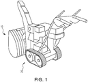
- FIG. 1 illustrates an embodiment of portable power equipment apparatus 10, which is illustrated as a snow blower.
- the power equipment apparatus 10 uses a hydrostatic transmission (HST) 100 of the type used with portable power equipment, such as snow blowers, lawn mowers, and similar equipment for converting torque from the engine 30 to rotation of the wheels 20.
- HST hydrostatic transmission
- the HST 100 includes a hydraulic pump 102 in fluid connection with a hydraulic motor 104. Versatility is achieved by making either or both the hydraulic pump 102 and hydraulic motor 104 variable displacement. The result is a continuously variable transmission (CVT).
- An HST 100 may be preferred over shifted gear transmission in many cases because of the stepless way in which the HST 100 speed ratio may be changed.
- the hydraulic pump 102 and the hydraulic motor 104 form a closed hydraulic circuit.
- the hydraulic pump 102 is externally driven by the engine 30 of the power equipment apparatus 10.
- the hydraulic pump 102 generates a flow of hydraulic fluid, which in turn drives the hydraulic motor 104.
- the hydraulic fluid is circulated between the hydraulic pump 102 and the hydraulic motor 104 by two lines, a first hydraulic line 106 and a second hydraulic line 108.
- the first hydraulic line 106 is a high pressure line for driving the hydraulic motor 104
- the second hydraulic line 108 is a low pressure line.
- the second hydraulic line 108 becomes the high pressure line in order to drive the hydraulic motor 104 in the opposite direction
- the first hydraulic line 106 becomes the low pressure line.
- the HST 100 can be broken down into three main components: a cover 110, a center section 112, and a main housing 114.
- the cover 110 represents the front portion of the HST 100 and provides the structure and housing for the hydraulic system in the center section 112.
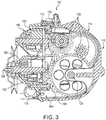
- the center section 112 defines the hydraulic circuit and is the location of the hydraulic pump 102, the hydraulic motor 104, the first and second hydraulic lines 106, 108, and the check valves 116, 117.
- the main housing 114 defines the gearbox 118 of the HST 100.
- the gears 120 of the gearbox 118 reduce the output of the hydraulic motor 104 to the output shaft 122, which turns the wheels 20 of the power equipment apparatus 10.
- the input shaft 124 of the HST 100 is turned by a V-belt and pulley system 40 coupled to the engine 30 as shown in FIG. 2 .
- the hydraulic pump 102 is turned by the input shaft 124. Rotation of the input shaft 124, and thus the hydraulic pump 102, is held at a constant speed and direction by the engine 30.
- a swash plate 126 is provided that is connected to the hydraulic pump 102 that is operated by a swash plate lever 128. As shown in FIGS. 6A-6C , the angle ⁇ of the swash plate 126 determines the direction of fluid flow. The angle ⁇ of the swash plate 126 alters the pressures in the first and second hydraulic lines 106, 108 in the center section 112. As an example, in FIG. 6A , the angle ⁇ is to the left of vertical v, and this represents movement in a forward direction. In FIG. 6B , the angle ⁇ is 0° from vertical, which represents neutral. In FIG. 6C , the angle ⁇ is to the right of vertical v, and this represents movement in a rearward direction.
- the first and second hydraulic lines 106, 108 are in fluid communication between the hydraulic pump 102 and the hydraulic motor 104.
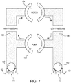
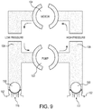
- the hydraulic motor 104 turns in either a clockwise direction (forward direction, illustrated in FIG. 7 , corresponding to swash plate 126 position illustrated in FIG. 6A ) or counter-clockwise direction (reverse direction, illustrated in FIG. 9 , corresponding to swash plate 126 position illustrated in FIG. 6C ) depending on the pressure differences in the first and second hydraulic lines 106, 108 created by the swash plate 126.
- the swash plate 126 is vertical, pressure is equalized between the first and second hydraulic lines 106, 108 and the hydraulic motor 104 does not rotate (neutral position, illustrated in FIG.
- the rotational speed of the hydraulic motor 104 is also related to the angle ⁇ of the swash plate 126. The greater the angle ⁇ of the swash plate 126, the faster the hydraulic motor 104 rotates.
- the motor shaft 130 meshes with the gears 120 in the main housing 120 to turn the output shaft 122, which in turn drives the wheels 20 of the power equipment apparatus 10.
- the pump block face 142 which is the sealing surface of hydraulic pump 102 illustrated in FIG. 12 , and which has an identical shape on the hydraulic motor 104 which is not illustrated, and the pump face 140 for each of the hydraulic pump 102 and hydraulic motor 104 located on center section 112 are each machined surfaces that rotate against one another.
- the sealing surface between the pump block face 142 and pump face 140 keeps the hydraulic fluid within the hydraulic pump 102 and hydraulic motor 104 reasonably well, but as increasing loads are applied to the HST output shaft 122, hydraulic fluid is lost through the sealing surface due to the high pressure spikes in the hydraulic circuit.
- the pump block face 142 further includes oil flow paths 144 that allow hydraulic fluid to flow out during a high pressure spike. The amount of hydraulic fluid lost through the sealing surface is proportionally related to the torque applied to the output shaft 122.
- the hydraulic fluid in the hydraulic circuit is entrained with cavitation bubbles 162, which limits the flow of the hydraulic fluid in the circuits and may limit the efficiency of the hydraulic circuit by reducing the pressure in the circuits. Air is easily compressible so the proper pressure in the circuit to turn the hydraulic motor 104 is not obtainable.
- an entrained air deflector 170 is provided.
- the entrained air deflector 170 prevents the flow of hydraulic fluid entrained with cavitation bubbles 162 into the check valve uptake area 160 by directing hydraulic fluid entrained with cavitation bubbles 162 away from the uptake area 160.
- the entrained air deflector 170 is placed around the seats 152 of the check valves 116, 117 to allow hydraulic fluid entrained with cavitation bubbles 162 to flow around the entrained air deflector 170 in the direction of arrow B upward due to the cavitation bubbles 162 in the hydraulic fluid.
- lighter hydraulic fluid entrained with cavitation bubbles 162 will rise while the heavier non-entrained hydraulic fluid will flow around the entrained air deflector 170 in the direction of arrow C towards the uptake area 160 to prevent the seats 152 from trapping or ingesting cavitation bubbles 162.
- the entrained air deflector 170 is of a rectangular or oval-type shape and attaches near the check valve uptake area 160.
- the entrained air deflector 170 encases the check valve uptake area 160 and protects the check valve seats 152 from hydraulic fluid entrained with cavitation bubbles 162.
- FIGS. 17-21 illustrate embodiments of the entrained air deflector 170.
- the entrained air deflector 170 includes a floor 172 positioned beneath the first check valve 116 and the second check valve 117.
- a wall 174 extends perpendicularly upward from an outer edge 176 of the floor 172.
- the wall 174 radially surrounds the first check valve 116 and the second check valve 117.
- the wall 174 may include an attachment hole 178 through which a fastener (not shown) may be passed.
- the fastener may be any fastener known to those skilled in the art, including but not limited to bolts, rivets, magnetic fasteners, or the like.
- the hole 178 may facilitate the entrained air deflector 170 being affixed to an extension 180 on the center section 112 of the HST 100 as shown in FIG. 3 .
- the entrained air deflector 170 may be made of any suitable thermoplastic material, such as a glass-filled polymer, which may be glass-filled nylon.
- FIG. 21 illustrates an alternate embodiment of the entrained air deflector which is squarer, as opposed to the rounder embodiment illustrated in FIGS. 17-20 .
Landscapes
- Engineering & Computer Science (AREA)
- General Engineering & Computer Science (AREA)
- Mechanical Engineering (AREA)
- Chemical & Material Sciences (AREA)
- Transportation (AREA)
- Combustion & Propulsion (AREA)
- Mining & Mineral Resources (AREA)
- Structural Engineering (AREA)
- Civil Engineering (AREA)
- Analytical Chemistry (AREA)
- Physics & Mathematics (AREA)
- Fluid Mechanics (AREA)
- Control Of Fluid Gearings (AREA)
- Motor Power Transmission Devices (AREA)
Abstract
Description
- The embodiments disclosed herein are related to the field of hydrostatic transmissions.
- Portable power equipment, such as snow blowers or similar apparatuses, typically use hydrostatic transmissions (HST) to operates. Due to cavitation within the HST, the HST loses efficiency due to air bubbles generated by the turning of the gears, particularly when the air bubbles get trapped in the check valve seats of the hydraulic circuit. Therefore, there is a need to prevent make-up oil entering through the check valve seats to be free of cavitation air bubbles.
- The features and advantages described in the specification are not all inclusive and, in particular, many additional features and advantages will be apparent to one of ordinary skill in the art in view of the drawings, specification, and claims. Moreover, it should be noted that the language used in the specification has been principally selected for readability and instructional purposes, and may not have been selected to delineate or circumscribe the inventive subject matter.
- According to one aspect, a hydrostatic transmission for a working machine having a frame, an engine on the frame, and at least one wheel driven by the hydrostatic transmission includes a housing, a hydraulic pump, the hydraulic pump driven by an output shaft from the engine, a hydraulic motor for driving an output shaft connected to the at least one wheel, a first fluid line fillable with hydraulic fluid to be maintained under a first pressure, a second fluid line fillable with hydraulic fluid to be maintained under a second pressure, a first check valve for allowing hydraulic fluid to enter the first fluid line, a second check valve for allowing hydraulic fluid to enter the second fluid line, and an entrained air deflector for preventing hydraulic fluid entrained with air from entering the first check valve and the second check valve.
- According to another aspect, a deflector for preventing air entrained fluid from entering first and second check valves includes a floor, the floor having an outer edge, the floor being positioned beneath the first check valve and the second check valve, and a wall extending perpendicularly upward from the outer edge of the floor, the wall radially surrounding the first check valve and the second check valve.
- According to yet another aspect, a hydrostatic transmission for a working machine having a frame, an engine on the frame, and at least one wheel driven by the hydrostatic transmission includes a housing, a hydraulic pump, the hydraulic pump driven by an output shaft from the engine for pumping hydraulic fluid, a hydraulic motor for driving an output shaft connected to the at least one wheel, a first fluid line transporting hydraulic fluid between the hydraulic pump and the hydraulic motor under a first pressure, a second fluid line transporting hydraulic fluid between the hydraulic pump and the hydraulic motor under a second pressure, a first check valve for allowing hydraulic fluid to enter the first fluid line, and a deflector for preventing hydraulic fluid entrained with air from entering the first check valve.
-
FIG. 1 is perspective view of a portable power equipment apparatus employing a hydrostatic transmission. -
FIG. 2 is an exploded perspective view of a drive train of the portable power equipment apparatus ofFIG. 1 . -
FIG. 3 is a cross-section of a hydrostatic transmission taken along Section A-A ofFIG. 2 presenting a side view. -
FIG. 4 is a rear view of the hydrostatic transmission with the main housing removed. -
FIG. 5 is a side view of the hydrostatic transmission with the main housing removed. -
FIG. 6A is a view of a swash plate and hydraulic pump with the swash plate angled for movement in a forward direction. -
FIG. 6B is a view of the swash plate and hydraulic pump with the swash plate angled for neutral operation. -
FIG. 6C is a view of the swash plate and hydraulic pump with the swash plate angled for movement in a rearward direction. -
FIG. 7 is a representation of a hydraulic circuit operating in a forward direction. -
FIG. 8 is a representation of a hydraulic circuit operating in neutral. -
FIG. 9 is a representation of a hydraulic circuit operating in a rearward direction. -
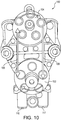
FIG. 10 is a front view of the hydrostatic transmission with the cover removed. -
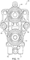
FIG. 11 is a front view of the hydrostatic transmission with the cover, the hydraulic pump, and the hydraulic motor removed to show the center section and the pump faces. -
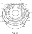
FIG. 12 is a top perspective view of the hydraulic pump showing the pump block face. -
FIG. 13 is the cross-section view of a hydrostatic transmission taken along Section A-A ofFIG. 2 showing the direction of hydraulic fluid flow in the hydrostatic transmission -
FIG. 14 is a representation of a hydraulic circuit operating in a forward direction with entrained cavitation bubbles. -
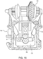
FIG. 15 is a rear view of the hydrostatic transmission with the main housing removed and an entrained air deflector installed. -
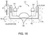
FIG. 16 is a plan view illustrating the operation of the entrained air deflector. -
FIG. 17 is a perspective view of an embodiment of the entrained air deflector. -
FIG. 18 is a top view of the embodiment of the entrained air deflector. -
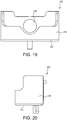
FIG. 19 is a front view of the embodiment of the entrained air deflector. -
FIG. 20 is a side view of the embodiment of the entrained air deflector. -
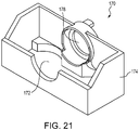
FIG. 21 is a perspective view of an alternate embodiment of the entrained air deflector. - The figures depict various embodiments for purposes of illustration only. One skilled in the art will readily recognize from the following discussion that alternative embodiments of the structures and methods illustrated herein may be employed without departing from the principles of the embodiments described herein.
-
FIG. 1 illustrates an embodiment of portablepower equipment apparatus 10, which is illustrated as a snow blower. As shown inFIG. 2 , thepower equipment apparatus 10 uses a hydrostatic transmission (HST) 100 of the type used with portable power equipment, such as snow blowers, lawn mowers, and similar equipment for converting torque from theengine 30 to rotation of thewheels 20. With reference toFIGS. 3-5 , the HST 100 includes ahydraulic pump 102 in fluid connection with ahydraulic motor 104. Versatility is achieved by making either or both thehydraulic pump 102 andhydraulic motor 104 variable displacement. The result is a continuously variable transmission (CVT). An HST 100 may be preferred over shifted gear transmission in many cases because of the stepless way in which the HST 100 speed ratio may be changed. - The
hydraulic pump 102 and thehydraulic motor 104 form a closed hydraulic circuit. Thehydraulic pump 102 is externally driven by theengine 30 of thepower equipment apparatus 10. Thehydraulic pump 102 generates a flow of hydraulic fluid, which in turn drives thehydraulic motor 104. The hydraulic fluid is circulated between thehydraulic pump 102 and thehydraulic motor 104 by two lines, a firsthydraulic line 106 and a secondhydraulic line 108. When the intention is to move thepower equipment apparatus 10 forward, the firsthydraulic line 106 is a high pressure line for driving thehydraulic motor 104, and the secondhydraulic line 108 is a low pressure line. When the intention is to move thepower equipment apparatus 10 in a reverse direction, the secondhydraulic line 108 becomes the high pressure line in order to drive thehydraulic motor 104 in the opposite direction, and the firsthydraulic line 106 becomes the low pressure line. - The HST 100 can be broken down into three main components: a
cover 110, acenter section 112, and amain housing 114. Thecover 110 represents the front portion of theHST 100 and provides the structure and housing for the hydraulic system in thecenter section 112. Thecenter section 112 defines the hydraulic circuit and is the location of thehydraulic pump 102, thehydraulic motor 104, the first and secondhydraulic lines check valves main housing 114 defines thegearbox 118 of the HST 100. Thegears 120 of thegearbox 118 reduce the output of thehydraulic motor 104 to theoutput shaft 122, which turns thewheels 20 of thepower equipment apparatus 10. - The
input shaft 124 of the HST 100 is turned by a V-belt andpulley system 40 coupled to theengine 30 as shown inFIG. 2 . Thehydraulic pump 102 is turned by theinput shaft 124. Rotation of theinput shaft 124, and thus thehydraulic pump 102, is held at a constant speed and direction by theengine 30. - A
swash plate 126 is provided that is connected to thehydraulic pump 102 that is operated by aswash plate lever 128. As shown inFIGS. 6A-6C , the angle α of theswash plate 126 determines the direction of fluid flow. The angle α of theswash plate 126 alters the pressures in the first and secondhydraulic lines center section 112. As an example, inFIG. 6A , the angle α is to the left of vertical v, and this represents movement in a forward direction. InFIG. 6B , the angle α is 0° from vertical, which represents neutral. InFIG. 6C , the angle α is to the right of vertical v, and this represents movement in a rearward direction. - The first and second
hydraulic lines hydraulic pump 102 and thehydraulic motor 104. Thehydraulic motor 104 turns in either a clockwise direction (forward direction, illustrated inFIG. 7 , corresponding toswash plate 126 position illustrated inFIG. 6A ) or counter-clockwise direction (reverse direction, illustrated inFIG. 9 , corresponding toswash plate 126 position illustrated inFIG. 6C ) depending on the pressure differences in the first and secondhydraulic lines swash plate 126. In the case where theswash plate 126 is vertical, pressure is equalized between the first and secondhydraulic lines hydraulic motor 104 does not rotate (neutral position, illustrated inFIG. 8 , corresponding toswash plate 126 position illustrated inFIG. 6B ). The rotational speed of thehydraulic motor 104 is also related to the angle α of theswash plate 126. The greater the angle α of theswash plate 126, the faster thehydraulic motor 104 rotates. Finally, themotor shaft 130 meshes with thegears 120 in themain housing 120 to turn theoutput shaft 122, which in turn drives thewheels 20 of thepower equipment apparatus 10. - Throughout the forward and reverse movement of the
swash plate lever 128, the pressure in each of the first and secondhydraulic lines swash plate 126. In an ideal situation, once the hydraulic circuit is filed with hydraulic fluid, no loss would occur. As shown inFIGS. 10-12 , thepump block face 142, which is the sealing surface ofhydraulic pump 102 illustrated inFIG. 12 , and which has an identical shape on thehydraulic motor 104 which is not illustrated, and thepump face 140 for each of thehydraulic pump 102 andhydraulic motor 104 located oncenter section 112 are each machined surfaces that rotate against one another. The sealing surface between thepump block face 142 and pumpface 140 keeps the hydraulic fluid within thehydraulic pump 102 andhydraulic motor 104 reasonably well, but as increasing loads are applied to theHST output shaft 122, hydraulic fluid is lost through the sealing surface due to the high pressure spikes in the hydraulic circuit. Thepump block face 142 further includesoil flow paths 144 that allow hydraulic fluid to flow out during a high pressure spike. The amount of hydraulic fluid lost through the sealing surface is proportionally related to the torque applied to theoutput shaft 122. - When hydraulic fluid is lost through
pump block face 142 of thehydraulic pump 102 andhydraulic motor 104, make up hydraulic fluid is added to the hydraulic circuit through one of twocheck valves check valves hydraulic lines HST 100 at the time. For example, in the forward direction example illustrated inFIG. 7 , hydraulic fluid may be added throughcheck valve 117. In the rearward direction example illustrated inFIG. 9 , hydraulic fluid may be added throughcheck valve 116. Thecheck valves hydraulic lines ball 150 into theseat 152, but if the pressure in the low pressure line of the first and secondhydraulic lines ball 150 is raised and fluid enters until pressure raises high enough to force theball 150 back into theseat 152. - With reference to
FIG. 13 , when the hydraulic fluid exits the hydraulic circuit, it passes through thegears 120 in themain housing 114. The churning of the hydraulic fluid through thegears 120 causes cavitation, or the introduction of pockets of air or air bubbles, called cavitation bubbles 162, into the hydraulic fluid. The drive gears 120 in themain housing 114 directs hydraulic fluid entrained withcavitation bubbles 162 to theuptake area 160 of thecheck valves check valves uptake area 160 and may operate to restrict the flow of hydraulic fluid into the first or secondhydraulic lines FIG. 14 , when the hydraulic fluid does enter the first or secondhydraulic lines cavitation bubbles 162, which limits the flow of the hydraulic fluid in the circuits and may limit the efficiency of the hydraulic circuit by reducing the pressure in the circuits. Air is easily compressible so the proper pressure in the circuit to turn thehydraulic motor 104 is not obtainable. - As illustrated in
FIG. 15 , which shows theHST 100 with the main housing In order to prevent the introduction of hydraulic fluid entrained withcavitation bubbles 162 into thecheck valves air deflector 170 is provided. The entrainedair deflector 170 prevents the flow of hydraulic fluid entrained withcavitation bubbles 162 into the checkvalve uptake area 160 by directing hydraulic fluid entrained withcavitation bubbles 162 away from theuptake area 160. As illustrated inFIG. 16 , the entrainedair deflector 170 is placed around theseats 152 of thecheck valves cavitation bubbles 162 to flow around the entrainedair deflector 170 in the direction of arrow B upward due to the cavitation bubbles 162 in the hydraulic fluid. Thus, lighter hydraulic fluid entrained withcavitation bubbles 162 will rise while the heavier non-entrained hydraulic fluid will flow around the entrainedair deflector 170 in the direction of arrow C towards theuptake area 160 to prevent theseats 152 from trapping or ingesting cavitation bubbles 162. The entrainedair deflector 170 is of a rectangular or oval-type shape and attaches near the checkvalve uptake area 160. The entrainedair deflector 170 encases the checkvalve uptake area 160 and protects thecheck valve seats 152 from hydraulic fluid entrained with cavitation bubbles 162. -
FIGS. 17-21 illustrate embodiments of the entrainedair deflector 170. In each embodiment, the entrainedair deflector 170 includes afloor 172 positioned beneath thefirst check valve 116 and thesecond check valve 117. Awall 174 extends perpendicularly upward from anouter edge 176 of thefloor 172. Thewall 174 radially surrounds thefirst check valve 116 and thesecond check valve 117. Further, thewall 174 may include anattachment hole 178 through which a fastener (not shown) may be passed. The fastener may be any fastener known to those skilled in the art, including but not limited to bolts, rivets, magnetic fasteners, or the like. Alternatively, thehole 178 may facilitate the entrainedair deflector 170 being affixed to anextension 180 on thecenter section 112 of theHST 100 as shown inFIG. 3 . The entrainedair deflector 170 may be made of any suitable thermoplastic material, such as a glass-filled polymer, which may be glass-filled nylon.FIG. 21 illustrates an alternate embodiment of the entrained air deflector which is squarer, as opposed to the rounder embodiment illustrated inFIGS. 17-20 . - Reference in the specification to "one embodiment" or to "an embodiment" means that a particular feature, structure, or characteristic described in connection with the embodiments is included in at least one embodiment. The appearances of the phrase "in one embodiment" or "an embodiment" in various places in the specification are not necessarily all referring to the same embodiment.
- In addition, the language used in the specification has been principally selected for readability and instructional purposes, and may not have been selected to delineate or circumscribe the inventive subject matter. Accordingly, the disclosure of the embodiments is intended to be illustrative, but not limiting, of the scope of the embodiments, which is set forth in the claims.
- While particular embodiments and applications have been illustrated and described herein, it is to be understood that the embodiments are not limited to the precise construction and components disclosed herein and that various modifications, changes, and variations may be made in the arrangement, operation, and details of the methods and apparatuses of the embodiments without departing from the spirit and scope of the embodiments as defined in the appended claims.
Claims (20)
- A hydrostatic transmission for a working machine having a frame, an engine (30) on the frame, and at least one wheel (20) driven by the hydrostatic transmission (100), comprising:a housing (114);a hydraulic pump (102), the hydraulic pump driven by an output shaft from the engine (30);a hydraulic motor (104) for driving an output shaft (130) connected to the at least one wheel (20);a first fluid line (106) fillable with hydraulic fluid to be maintained under a first pressure;a second fluid line (108) fillable with hydraulic fluid to be maintained under a second pressure;a first check valve (116) for allowing hydraulic fluid to enter the first fluid line (106);a second check valve (118) for allowing hydraulic fluid to enter the second fluid line (108); andan entrained air deflector (170) for preventing hydraulic fluid entrained with air from entering the first check valve (116) and the second check valve (118).
- The hydrostatic transmission of claim 1 wherein the entrained air deflector comprises:a floor (172), the floor (172) having an outer edge (176), the floor (172) being positioned beneath the first check valve (116) and the second check valve (118); anda wall (174) extending perpendicularly upward from the outer edge (176) of the floor (172), the wall (174) radially surrounding the first check valve (116) and the second check valve (118).
- The hydrostatic transmission of claim 2 wherein the wall (174) of the entrained air deflector (170) includes an opening (178) for receiving a fastener.
- The hydrostatic transmission of any one of claims 1 to 3 wherein the entrained air deflector (170) is comprised of a glass-filled polymer.
- The hydrostatic transmission of any one of claims 1 to 4 wherein the glass-filled polymer is glass-filled nylon.
- A deflector for preventing air entrained fluid from entering first and second check valves (116, 118), comprising:a floor (172), the floor (172) having an outer edge (176), the floor (172) being positioned beneath the first check valve (116) and the second check valve (118); anda wall (174) extending upwardly from the outer edge (176) of the floor (170), the wall (174) radially surrounding the first check valve (116) and the second check valve (118).
- The deflector of claim 6 further comprising:an opening (178) for receiving a fastener.
- The deflector of claim 6 or 7 wherein the floor (172) and wall (174) are comprised of a glass-filled polymer.
- The deflector of claim 6 or 8 wherein the glass-filled polymer is glass-filled nylon.
- A hydrostatic transmission for a working machine having a frame, an engine (30) on the frame, and at least one wheel (20) driven by the hydrostatic transmission (100), comprising:a housing (114);a hydraulic pump (102), the hydraulic pump (102) driven by an output shaft from the engine (30) for pumping hydraulic fluid;a hydraulic motor (104) for driving an output shaft (130) connected to the at least one wheel (20);a first fluid line (106) transporting hydraulic fluid between the hydraulic pump (102) and the hydraulic motor (104) under a first pressure;a second fluid line (108) transporting hydraulic fluid between the hydraulic pump (102) and the hydraulic motor (104) under a second pressure;a first check valve (116) for allowing hydraulic fluid to enter the first fluid line (106); anda deflector (170) for preventing hydraulic fluid entrained with air from entering the first check valve (116).
- The hydrostatic transmission of claim 10 further comprising:a second check valve (118) for allowing hydraulic fluid to enter the second fluid line (108).
- The hydrostatic transmission of claim 10 or 11 wherein the deflector (170) prevents hydraulic fluid entrained with air from entering the second check valve (118).
- The hydrostatic transmission of any one of claims 10 to 12 wherein the deflector comprises:a floor (172), the floor (172) having an outer edge (176), the floor (172) being positioned beneath the first check valve (116) and the second check valve (118); anda wall (174) extending upwardly from the outer edge (176) of the floor (172), the wall (174) radially surrounding the first check valve (116) and the second check valve (118).
- The hydrostatic transmission of claim 13 wherein the wall (174) of the deflector (170) includes an opening (178) for receiving a fastener.
- The hydrostatic transmission of any one of claims 10 to 14 wherein the deflector (170) is comprised of a glass-filled polymer.
- The hydrostatic transmission of any one of claims 10 to 15 wherein the glass-filled polymer is glass-filled nylon.
- The hydrostatic transmission of any one of claims 10 to 13 wherein hydraulic fluid comprises:air entrained hydraulic fluid; andnon-entrained hydraulic fluid.
- The hydrostatic transmission of any one of claims 10 to 17 wherein air entrained hydraulic fluid rises around the deflector (170).
- The hydrostatic transmission of claim 13 and any one of claims 14 to 18 wherein non-entrained hydraulic fluid flows over the wall (174) of the deflector onto the floor (172) of the deflector (170).
- The hydrostatic transmission of any one of claims 10 to 19 wherein non-entrained hydraulic fluid comes into fluid contact with the first check valve (116) and the second check valve (118).
Applications Claiming Priority (1)
| Application Number | Priority Date | Filing Date | Title |
|---|---|---|---|
| US15/471,442 US10281035B2 (en) | 2017-03-28 | 2017-03-28 | Entrained air deflector for a hydrostatic transmission |
Publications (2)
| Publication Number | Publication Date |
|---|---|
| EP3382106A1 true EP3382106A1 (en) | 2018-10-03 |
| EP3382106B1 EP3382106B1 (en) | 2019-10-30 |
Family
ID=61768073
Family Applications (1)
| Application Number | Title | Priority Date | Filing Date |
|---|---|---|---|
| EP18163265.4A Active EP3382106B1 (en) | 2017-03-28 | 2018-03-22 | Entrained air deflector for a hydrostatic transmission |
Country Status (5)
| Country | Link |
|---|---|
| US (1) | US10281035B2 (en) |
| EP (1) | EP3382106B1 (en) |
| JP (1) | JP7280016B2 (en) |
| CN (1) | CN108662110B (en) |
| CA (1) | CA2998024C (en) |
Citations (4)
| Publication number | Priority date | Publication date | Assignee | Title |
|---|---|---|---|---|
| US20030226774A1 (en) * | 2002-06-11 | 2003-12-11 | Elsegood Stewart D. | Fluid flow test kit |
| US6691511B1 (en) * | 2002-03-13 | 2004-02-17 | Hydro-Gear Limited Partnership | Filter for hydrostatic transmission |
| US8464610B1 (en) * | 2008-08-01 | 2013-06-18 | Hydro-Gear Limited Partnership | Drive device |
| US20150075155A1 (en) * | 2013-07-05 | 2015-03-19 | Kanzaki Kokyukoki Mfg. Co., Ltd. | Apparatus including hydrostatic transmission |
Family Cites Families (18)
| Publication number | Priority date | Publication date | Assignee | Title |
|---|---|---|---|---|
| JPS6148909U (en) * | 1984-08-28 | 1986-04-02 | ||
| US5373697A (en) * | 1991-07-22 | 1994-12-20 | Tecumseh Products Company | Hydraulic fluid system and dump valve mechanism for a hydrostatic transaxle |
| JP3571743B2 (en) * | 1993-12-02 | 2004-09-29 | ヤンマー株式会社 | HST hydraulic motor anti-spin device |
| US6125630A (en) | 1995-10-27 | 2000-10-03 | Tuff Torq Corporation | Axle driving apparatus |
| JPH09189350A (en) * | 1996-01-09 | 1997-07-22 | Kanzaki Kokyukoki Mfg Co Ltd | Axle driving device |
| DE19727205A1 (en) | 1996-06-29 | 1998-12-24 | Luk Fahrzeug Hydraulik | Oil suction filter for automatic gearboxes |
| US8066415B2 (en) * | 1999-06-17 | 2011-11-29 | Magna Mirrors Of America, Inc. | Exterior mirror vision system for a vehicle |
| CA2348197C (en) * | 2000-05-31 | 2005-04-26 | Honda Giken Kogyo Kabushiki Kaisha | Hydrostatic continuously variable transmission |
| DE20218576U1 (en) | 2002-11-30 | 2003-03-06 | AS-Antriebstechnik und Service GmbH, 48734 Reken | Air bubble separator for oil circuit has in inlet section behind oil inlet perforated retaining plates for oil-permeable column and connected one behind other in direction of flow |
| JP4464233B2 (en) | 2004-09-21 | 2010-05-19 | ジヤトコ株式会社 | Oil splitting structure in automatic transmission |
| JP4940633B2 (en) | 2005-11-09 | 2012-05-30 | 日産自動車株式会社 | Air breather device |
| JP2009227082A (en) * | 2008-03-21 | 2009-10-08 | Kanzaki Kokyukoki Mfg Co Ltd | Working vehicle and hst unit |
| JP5124371B2 (en) * | 2008-07-03 | 2013-01-23 | ザウアーダンフォス・ダイキン株式会社 | Transmission |
| US8534060B1 (en) | 2008-08-01 | 2013-09-17 | Hydro-Gear Limited Partnership | Drive device |
| DE102009058005B4 (en) * | 2009-12-11 | 2012-01-26 | Hydac System Gmbh | Hydrostatic drive |
| DE102010019434A1 (en) * | 2010-05-05 | 2011-11-10 | Robert Bosch Gmbh | Hydrostatic energy storage |
| JP5850675B2 (en) * | 2011-09-06 | 2016-02-03 | 高安株式会社 | Nylon resin composition |
| US9453519B2 (en) | 2013-07-05 | 2016-09-27 | Kanzaki Kokyukoki Mfg. Co., Ltd. | Transaxle |
-
2017
- 2017-03-28 US US15/471,442 patent/US10281035B2/en active Active
-
2018
- 2018-03-13 CA CA2998024A patent/CA2998024C/en active Active
- 2018-03-14 JP JP2018047115A patent/JP7280016B2/en active Active
- 2018-03-22 CN CN201810238778.4A patent/CN108662110B/en not_active Expired - Fee Related
- 2018-03-22 EP EP18163265.4A patent/EP3382106B1/en active Active
Patent Citations (4)
| Publication number | Priority date | Publication date | Assignee | Title |
|---|---|---|---|---|
| US6691511B1 (en) * | 2002-03-13 | 2004-02-17 | Hydro-Gear Limited Partnership | Filter for hydrostatic transmission |
| US20030226774A1 (en) * | 2002-06-11 | 2003-12-11 | Elsegood Stewart D. | Fluid flow test kit |
| US8464610B1 (en) * | 2008-08-01 | 2013-06-18 | Hydro-Gear Limited Partnership | Drive device |
| US20150075155A1 (en) * | 2013-07-05 | 2015-03-19 | Kanzaki Kokyukoki Mfg. Co., Ltd. | Apparatus including hydrostatic transmission |
Also Published As
| Publication number | Publication date |
|---|---|
| JP2018200100A (en) | 2018-12-20 |
| CN108662110B (en) | 2022-12-23 |
| US20180283546A1 (en) | 2018-10-04 |
| CN108662110A (en) | 2018-10-16 |
| US10281035B2 (en) | 2019-05-07 |
| JP7280016B2 (en) | 2023-05-23 |
| EP3382106B1 (en) | 2019-10-30 |
| CA2998024C (en) | 2022-11-22 |
| CA2998024A1 (en) | 2018-09-28 |
Similar Documents
| Publication | Publication Date | Title |
|---|---|---|
| RU2695240C2 (en) | Fan unit, operation method thereof and vehicle | |
| US9211793B2 (en) | Vehicle transaxle system | |
| US10315747B1 (en) | Outboard motors having transmissions with laterally offset input and output driveshafts | |
| US9109684B1 (en) | Drive device | |
| CN106567921A (en) | Variable baffle that reduces oil at the gear mesh | |
| US6151990A (en) | Hydrostatic transaxle having a casing split along one or more vertical planes | |
| US7007571B1 (en) | Hydrostatic transmission | |
| US7690198B2 (en) | Integrated hystat having single input and independent output | |
| JPS63284037A (en) | Auxiliary driving wheel drive | |
| EP3382106B1 (en) | Entrained air deflector for a hydrostatic transmission | |
| DE102010060972B4 (en) | Arrangement for driving a first and second radial fan | |
| KR0159519B1 (en) | Hydromechanical steering transmission with improved high range speed performance | |
| KR20180090015A (en) | Hydro Static Transmission and Swash plate controlling methods of Hydro Static Transmission | |
| US5687808A (en) | Four wheel drive mechanism | |
| US7377354B2 (en) | Four wheel traction control valve system | |
| EP3181954A2 (en) | Hydraulic system for a torque converter | |
| US7299891B2 (en) | Hydraulic drive mechanism for mobile vehicles | |
| US4981201A (en) | Variable drive apparatus | |
| KR20180090016A (en) | Hydro Static Transmission and control methods | |
| JP2003184990A (en) | Transmission mechanism of mobile farm machine | |
| JP3201659B2 (en) | Power take-out device for transmission | |
| JP3452037B2 (en) | Transmission mechanism of traveling device in combine | |
| KR100426539B1 (en) | Continuously variable transmission | |
| JPH1194076A (en) | Hydrostatic pressure type transmission | |
| JP3760951B2 (en) | Combine drive transmission |
Legal Events
| Date | Code | Title | Description |
|---|---|---|---|
| PUAI | Public reference made under article 153(3) epc to a published international application that has entered the european phase |
Free format text: ORIGINAL CODE: 0009012 |
|
| STAA | Information on the status of an ep patent application or granted ep patent |
Free format text: STATUS: REQUEST FOR EXAMINATION WAS MADE |
|
| 17P | Request for examination filed |
Effective date: 20180322 |
|
| AK | Designated contracting states |
Kind code of ref document: A1 Designated state(s): AL AT BE BG CH CY CZ DE DK EE ES FI FR GB GR HR HU IE IS IT LI LT LU LV MC MK MT NL NO PL PT RO RS SE SI SK SM TR |
|
| AX | Request for extension of the european patent |
Extension state: BA ME |
|
| GRAP | Despatch of communication of intention to grant a patent |
Free format text: ORIGINAL CODE: EPIDOSNIGR1 |
|
| STAA | Information on the status of an ep patent application or granted ep patent |
Free format text: STATUS: GRANT OF PATENT IS INTENDED |
|
| INTG | Intention to grant announced |
Effective date: 20190529 |
|
| GRAS | Grant fee paid |
Free format text: ORIGINAL CODE: EPIDOSNIGR3 |
|
| GRAA | (expected) grant |
Free format text: ORIGINAL CODE: 0009210 |
|
| STAA | Information on the status of an ep patent application or granted ep patent |
Free format text: STATUS: THE PATENT HAS BEEN GRANTED |
|
| AK | Designated contracting states |
Kind code of ref document: B1 Designated state(s): AL AT BE BG CH CY CZ DE DK EE ES FI FR GB GR HR HU IE IS IT LI LT LU LV MC MK MT NL NO PL PT RO RS SE SI SK SM TR |
|
| REG | Reference to a national code |
Ref country code: GB Ref legal event code: FG4D |
|
| REG | Reference to a national code |
Ref country code: CH Ref legal event code: EP |
|
| REG | Reference to a national code |
Ref country code: AT Ref legal event code: REF Ref document number: 1196271 Country of ref document: AT Kind code of ref document: T Effective date: 20191115 |
|
| REG | Reference to a national code |
Ref country code: DE Ref legal event code: R096 Ref document number: 602018001007 Country of ref document: DE |
|
| REG | Reference to a national code |
Ref country code: IE Ref legal event code: FG4D |
|
| REG | Reference to a national code |
Ref country code: LT Ref legal event code: MG4D |
|
| PG25 | Lapsed in a contracting state [announced via postgrant information from national office to epo] |
Ref country code: FI Free format text: LAPSE BECAUSE OF FAILURE TO SUBMIT A TRANSLATION OF THE DESCRIPTION OR TO PAY THE FEE WITHIN THE PRESCRIBED TIME-LIMIT Effective date: 20191030 Ref country code: BG Free format text: LAPSE BECAUSE OF FAILURE TO SUBMIT A TRANSLATION OF THE DESCRIPTION OR TO PAY THE FEE WITHIN THE PRESCRIBED TIME-LIMIT Effective date: 20200130 Ref country code: NO Free format text: LAPSE BECAUSE OF FAILURE TO SUBMIT A TRANSLATION OF THE DESCRIPTION OR TO PAY THE FEE WITHIN THE PRESCRIBED TIME-LIMIT Effective date: 20200130 Ref country code: PT Free format text: LAPSE BECAUSE OF FAILURE TO SUBMIT A TRANSLATION OF THE DESCRIPTION OR TO PAY THE FEE WITHIN THE PRESCRIBED TIME-LIMIT Effective date: 20200302 Ref country code: SE Free format text: LAPSE BECAUSE OF FAILURE TO SUBMIT A TRANSLATION OF THE DESCRIPTION OR TO PAY THE FEE WITHIN THE PRESCRIBED TIME-LIMIT Effective date: 20191030 Ref country code: LV Free format text: LAPSE BECAUSE OF FAILURE TO SUBMIT A TRANSLATION OF THE DESCRIPTION OR TO PAY THE FEE WITHIN THE PRESCRIBED TIME-LIMIT Effective date: 20191030 Ref country code: PL Free format text: LAPSE BECAUSE OF FAILURE TO SUBMIT A TRANSLATION OF THE DESCRIPTION OR TO PAY THE FEE WITHIN THE PRESCRIBED TIME-LIMIT Effective date: 20191030 Ref country code: LT Free format text: LAPSE BECAUSE OF FAILURE TO SUBMIT A TRANSLATION OF THE DESCRIPTION OR TO PAY THE FEE WITHIN THE PRESCRIBED TIME-LIMIT Effective date: 20191030 Ref country code: NL Free format text: LAPSE BECAUSE OF FAILURE TO SUBMIT A TRANSLATION OF THE DESCRIPTION OR TO PAY THE FEE WITHIN THE PRESCRIBED TIME-LIMIT Effective date: 20191030 Ref country code: GR Free format text: LAPSE BECAUSE OF FAILURE TO SUBMIT A TRANSLATION OF THE DESCRIPTION OR TO PAY THE FEE WITHIN THE PRESCRIBED TIME-LIMIT Effective date: 20200131 |
|
| REG | Reference to a national code |
Ref country code: NL Ref legal event code: MP Effective date: 20191030 |
|
| PG25 | Lapsed in a contracting state [announced via postgrant information from national office to epo] |
Ref country code: RS Free format text: LAPSE BECAUSE OF FAILURE TO SUBMIT A TRANSLATION OF THE DESCRIPTION OR TO PAY THE FEE WITHIN THE PRESCRIBED TIME-LIMIT Effective date: 20191030 Ref country code: IS Free format text: LAPSE BECAUSE OF FAILURE TO SUBMIT A TRANSLATION OF THE DESCRIPTION OR TO PAY THE FEE WITHIN THE PRESCRIBED TIME-LIMIT Effective date: 20200229 Ref country code: HR Free format text: LAPSE BECAUSE OF FAILURE TO SUBMIT A TRANSLATION OF THE DESCRIPTION OR TO PAY THE FEE WITHIN THE PRESCRIBED TIME-LIMIT Effective date: 20191030 |
|
| PG25 | Lapsed in a contracting state [announced via postgrant information from national office to epo] |
Ref country code: AL Free format text: LAPSE BECAUSE OF FAILURE TO SUBMIT A TRANSLATION OF THE DESCRIPTION OR TO PAY THE FEE WITHIN THE PRESCRIBED TIME-LIMIT Effective date: 20191030 |
|
| PG25 | Lapsed in a contracting state [announced via postgrant information from national office to epo] |
Ref country code: CZ Free format text: LAPSE BECAUSE OF FAILURE TO SUBMIT A TRANSLATION OF THE DESCRIPTION OR TO PAY THE FEE WITHIN THE PRESCRIBED TIME-LIMIT Effective date: 20191030 Ref country code: ES Free format text: LAPSE BECAUSE OF FAILURE TO SUBMIT A TRANSLATION OF THE DESCRIPTION OR TO PAY THE FEE WITHIN THE PRESCRIBED TIME-LIMIT Effective date: 20191030 Ref country code: RO Free format text: LAPSE BECAUSE OF FAILURE TO SUBMIT A TRANSLATION OF THE DESCRIPTION OR TO PAY THE FEE WITHIN THE PRESCRIBED TIME-LIMIT Effective date: 20191030 Ref country code: EE Free format text: LAPSE BECAUSE OF FAILURE TO SUBMIT A TRANSLATION OF THE DESCRIPTION OR TO PAY THE FEE WITHIN THE PRESCRIBED TIME-LIMIT Effective date: 20191030 Ref country code: DK Free format text: LAPSE BECAUSE OF FAILURE TO SUBMIT A TRANSLATION OF THE DESCRIPTION OR TO PAY THE FEE WITHIN THE PRESCRIBED TIME-LIMIT Effective date: 20191030 |
|
| REG | Reference to a national code |
Ref country code: DE Ref legal event code: R097 Ref document number: 602018001007 Country of ref document: DE |
|
| REG | Reference to a national code |
Ref country code: AT Ref legal event code: MK05 Ref document number: 1196271 Country of ref document: AT Kind code of ref document: T Effective date: 20191030 |
|
| PG25 | Lapsed in a contracting state [announced via postgrant information from national office to epo] |
Ref country code: SK Free format text: LAPSE BECAUSE OF FAILURE TO SUBMIT A TRANSLATION OF THE DESCRIPTION OR TO PAY THE FEE WITHIN THE PRESCRIBED TIME-LIMIT Effective date: 20191030 Ref country code: IT Free format text: LAPSE BECAUSE OF FAILURE TO SUBMIT A TRANSLATION OF THE DESCRIPTION OR TO PAY THE FEE WITHIN THE PRESCRIBED TIME-LIMIT Effective date: 20191030 Ref country code: SM Free format text: LAPSE BECAUSE OF FAILURE TO SUBMIT A TRANSLATION OF THE DESCRIPTION OR TO PAY THE FEE WITHIN THE PRESCRIBED TIME-LIMIT Effective date: 20191030 |
|
| PLBE | No opposition filed within time limit |
Free format text: ORIGINAL CODE: 0009261 |
|
| STAA | Information on the status of an ep patent application or granted ep patent |
Free format text: STATUS: NO OPPOSITION FILED WITHIN TIME LIMIT |
|
| 26N | No opposition filed |
Effective date: 20200731 |
|
| PG25 | Lapsed in a contracting state [announced via postgrant information from national office to epo] |
Ref country code: MC Free format text: LAPSE BECAUSE OF FAILURE TO SUBMIT A TRANSLATION OF THE DESCRIPTION OR TO PAY THE FEE WITHIN THE PRESCRIBED TIME-LIMIT Effective date: 20191030 |
|
| PG25 | Lapsed in a contracting state [announced via postgrant information from national office to epo] |
Ref country code: AT Free format text: LAPSE BECAUSE OF FAILURE TO SUBMIT A TRANSLATION OF THE DESCRIPTION OR TO PAY THE FEE WITHIN THE PRESCRIBED TIME-LIMIT Effective date: 20191030 Ref country code: SI Free format text: LAPSE BECAUSE OF FAILURE TO SUBMIT A TRANSLATION OF THE DESCRIPTION OR TO PAY THE FEE WITHIN THE PRESCRIBED TIME-LIMIT Effective date: 20191030 |
|
| REG | Reference to a national code |
Ref country code: BE Ref legal event code: MM Effective date: 20200331 |
|
| PG25 | Lapsed in a contracting state [announced via postgrant information from national office to epo] |
Ref country code: LU Free format text: LAPSE BECAUSE OF NON-PAYMENT OF DUE FEES Effective date: 20200322 |
|
| PG25 | Lapsed in a contracting state [announced via postgrant information from national office to epo] |
Ref country code: FR Free format text: LAPSE BECAUSE OF NON-PAYMENT OF DUE FEES Effective date: 20200331 Ref country code: IE Free format text: LAPSE BECAUSE OF NON-PAYMENT OF DUE FEES Effective date: 20200322 |
|
| PG25 | Lapsed in a contracting state [announced via postgrant information from national office to epo] |
Ref country code: BE Free format text: LAPSE BECAUSE OF NON-PAYMENT OF DUE FEES Effective date: 20200331 |
|
| REG | Reference to a national code |
Ref country code: CH Ref legal event code: PL |
|
| PG25 | Lapsed in a contracting state [announced via postgrant information from national office to epo] |
Ref country code: CH Free format text: LAPSE BECAUSE OF NON-PAYMENT OF DUE FEES Effective date: 20210331 Ref country code: LI Free format text: LAPSE BECAUSE OF NON-PAYMENT OF DUE FEES Effective date: 20210331 |
|
| PG25 | Lapsed in a contracting state [announced via postgrant information from national office to epo] |
Ref country code: TR Free format text: LAPSE BECAUSE OF FAILURE TO SUBMIT A TRANSLATION OF THE DESCRIPTION OR TO PAY THE FEE WITHIN THE PRESCRIBED TIME-LIMIT Effective date: 20191030 Ref country code: MT Free format text: LAPSE BECAUSE OF FAILURE TO SUBMIT A TRANSLATION OF THE DESCRIPTION OR TO PAY THE FEE WITHIN THE PRESCRIBED TIME-LIMIT Effective date: 20191030 Ref country code: CY Free format text: LAPSE BECAUSE OF FAILURE TO SUBMIT A TRANSLATION OF THE DESCRIPTION OR TO PAY THE FEE WITHIN THE PRESCRIBED TIME-LIMIT Effective date: 20191030 |
|
| PG25 | Lapsed in a contracting state [announced via postgrant information from national office to epo] |
Ref country code: MK Free format text: LAPSE BECAUSE OF FAILURE TO SUBMIT A TRANSLATION OF THE DESCRIPTION OR TO PAY THE FEE WITHIN THE PRESCRIBED TIME-LIMIT Effective date: 20191030 |
|
| GBPC | Gb: european patent ceased through non-payment of renewal fee |
Effective date: 20220322 |
|
| PG25 | Lapsed in a contracting state [announced via postgrant information from national office to epo] |
Ref country code: GB Free format text: LAPSE BECAUSE OF NON-PAYMENT OF DUE FEES Effective date: 20220322 |
|
| PGFP | Annual fee paid to national office [announced via postgrant information from national office to epo] |
Ref country code: DE Payment date: 20230125 Year of fee payment: 6 |
|
| REG | Reference to a national code |
Ref country code: DE Ref legal event code: R119 Ref document number: 602018001007 Country of ref document: DE |
|
| PG25 | Lapsed in a contracting state [announced via postgrant information from national office to epo] |
Ref country code: DE Free format text: LAPSE BECAUSE OF NON-PAYMENT OF DUE FEES Effective date: 20241001 |
|
| PG25 | Lapsed in a contracting state [announced via postgrant information from national office to epo] |
Ref country code: DE Free format text: LAPSE BECAUSE OF NON-PAYMENT OF DUE FEES Effective date: 20241001 |