EP3381779A1 - Structure of rocking controller of saddle riding type vehicle - Google Patents
Structure of rocking controller of saddle riding type vehicle Download PDFInfo
- Publication number
- EP3381779A1 EP3381779A1 EP18158884.9A EP18158884A EP3381779A1 EP 3381779 A1 EP3381779 A1 EP 3381779A1 EP 18158884 A EP18158884 A EP 18158884A EP 3381779 A1 EP3381779 A1 EP 3381779A1
- Authority
- EP
- European Patent Office
- Prior art keywords
- rocking
- lock
- vehicle body
- actuator
- shaft
- Prior art date
- Legal status (The legal status is an assumption and is not a legal conclusion. Google has not performed a legal analysis and makes no representation as to the accuracy of the status listed.)
- Granted
Links
Images



Classifications
-
- B—PERFORMING OPERATIONS; TRANSPORTING
- B60—VEHICLES IN GENERAL
- B60G—VEHICLE SUSPENSION ARRANGEMENTS
- B60G17/00—Resilient suspensions having means for adjusting the spring or vibration-damper characteristics, for regulating the distance between a supporting surface and a sprung part of vehicle or for locking suspension during use to meet varying vehicular or surface conditions, e.g. due to speed or load
- B60G17/015—Resilient suspensions having means for adjusting the spring or vibration-damper characteristics, for regulating the distance between a supporting surface and a sprung part of vehicle or for locking suspension during use to meet varying vehicular or surface conditions, e.g. due to speed or load the regulating means comprising electric or electronic elements
- B60G17/0152—Resilient suspensions having means for adjusting the spring or vibration-damper characteristics, for regulating the distance between a supporting surface and a sprung part of vehicle or for locking suspension during use to meet varying vehicular or surface conditions, e.g. due to speed or load the regulating means comprising electric or electronic elements characterised by the action on a particular type of suspension unit
- B60G17/0157—Resilient suspensions having means for adjusting the spring or vibration-damper characteristics, for regulating the distance between a supporting surface and a sprung part of vehicle or for locking suspension during use to meet varying vehicular or surface conditions, e.g. due to speed or load the regulating means comprising electric or electronic elements characterised by the action on a particular type of suspension unit non-fluid unit, e.g. electric motor
-
- B—PERFORMING OPERATIONS; TRANSPORTING
- B60—VEHICLES IN GENERAL
- B60G—VEHICLE SUSPENSION ARRANGEMENTS
- B60G21/00—Interconnection systems for two or more resiliently-suspended wheels, e.g. for stabilising a vehicle body with respect to acceleration, deceleration or centrifugal forces
- B60G21/007—Interconnection systems for two or more resiliently-suspended wheels, e.g. for stabilising a vehicle body with respect to acceleration, deceleration or centrifugal forces means for adjusting the wheel inclination
-
- B—PERFORMING OPERATIONS; TRANSPORTING
- B60—VEHICLES IN GENERAL
- B60G—VEHICLE SUSPENSION ARRANGEMENTS
- B60G21/00—Interconnection systems for two or more resiliently-suspended wheels, e.g. for stabilising a vehicle body with respect to acceleration, deceleration or centrifugal forces
- B60G21/02—Interconnection systems for two or more resiliently-suspended wheels, e.g. for stabilising a vehicle body with respect to acceleration, deceleration or centrifugal forces permanently interconnected
- B60G21/04—Interconnection systems for two or more resiliently-suspended wheels, e.g. for stabilising a vehicle body with respect to acceleration, deceleration or centrifugal forces permanently interconnected mechanically
- B60G21/05—Interconnection systems for two or more resiliently-suspended wheels, e.g. for stabilising a vehicle body with respect to acceleration, deceleration or centrifugal forces permanently interconnected mechanically between wheels on the same axle but on different sides of the vehicle, i.e. the left and right wheel suspensions being interconnected
-
- B—PERFORMING OPERATIONS; TRANSPORTING
- B62—LAND VEHICLES FOR TRAVELLING OTHERWISE THAN ON RAILS
- B62K—CYCLES; CYCLE FRAMES; CYCLE STEERING DEVICES; RIDER-OPERATED TERMINAL CONTROLS SPECIALLY ADAPTED FOR CYCLES; CYCLE AXLE SUSPENSIONS; CYCLE SIDECARS, FORECARS, OR THE LIKE
- B62K5/00—Cycles with handlebars, equipped with three or more main road wheels
- B62K5/02—Tricycles
- B62K5/027—Motorcycles with three wheels
-
- B—PERFORMING OPERATIONS; TRANSPORTING
- B62—LAND VEHICLES FOR TRAVELLING OTHERWISE THAN ON RAILS
- B62K—CYCLES; CYCLE FRAMES; CYCLE STEERING DEVICES; RIDER-OPERATED TERMINAL CONTROLS SPECIALLY ADAPTED FOR CYCLES; CYCLE AXLE SUSPENSIONS; CYCLE SIDECARS, FORECARS, OR THE LIKE
- B62K5/00—Cycles with handlebars, equipped with three or more main road wheels
- B62K5/02—Tricycles
- B62K5/05—Tricycles characterised by a single rear wheel
-
- B—PERFORMING OPERATIONS; TRANSPORTING
- B62—LAND VEHICLES FOR TRAVELLING OTHERWISE THAN ON RAILS
- B62K—CYCLES; CYCLE FRAMES; CYCLE STEERING DEVICES; RIDER-OPERATED TERMINAL CONTROLS SPECIALLY ADAPTED FOR CYCLES; CYCLE AXLE SUSPENSIONS; CYCLE SIDECARS, FORECARS, OR THE LIKE
- B62K5/00—Cycles with handlebars, equipped with three or more main road wheels
- B62K5/08—Cycles with handlebars, equipped with three or more main road wheels with steering devices acting on two or more wheels
-
- B—PERFORMING OPERATIONS; TRANSPORTING
- B62—LAND VEHICLES FOR TRAVELLING OTHERWISE THAN ON RAILS
- B62K—CYCLES; CYCLE FRAMES; CYCLE STEERING DEVICES; RIDER-OPERATED TERMINAL CONTROLS SPECIALLY ADAPTED FOR CYCLES; CYCLE AXLE SUSPENSIONS; CYCLE SIDECARS, FORECARS, OR THE LIKE
- B62K5/00—Cycles with handlebars, equipped with three or more main road wheels
- B62K5/10—Cycles with handlebars, equipped with three or more main road wheels with means for inwardly inclining the vehicle body on bends
-
- B—PERFORMING OPERATIONS; TRANSPORTING
- B60—VEHICLES IN GENERAL
- B60G—VEHICLE SUSPENSION ARRANGEMENTS
- B60G2202/00—Indexing codes relating to the type of spring, damper or actuator
- B60G2202/40—Type of actuator
- B60G2202/42—Electric actuator
-
- B—PERFORMING OPERATIONS; TRANSPORTING
- B60—VEHICLES IN GENERAL
- B60G—VEHICLE SUSPENSION ARRANGEMENTS
- B60G2202/00—Indexing codes relating to the type of spring, damper or actuator
- B60G2202/40—Type of actuator
- B60G2202/442—Rotary actuator
-
- B—PERFORMING OPERATIONS; TRANSPORTING
- B60—VEHICLES IN GENERAL
- B60G—VEHICLE SUSPENSION ARRANGEMENTS
- B60G2204/00—Indexing codes related to suspensions per se or to auxiliary parts
- B60G2204/40—Auxiliary suspension parts; Adjustment of suspensions
- B60G2204/46—Means for locking the suspension
- B60G2204/4604—Means for locking the suspension mechanically, e.g. using a hook as anticreep mechanism
-
- B—PERFORMING OPERATIONS; TRANSPORTING
- B60—VEHICLES IN GENERAL
- B60G—VEHICLE SUSPENSION ARRANGEMENTS
- B60G2204/00—Indexing codes related to suspensions per se or to auxiliary parts
- B60G2204/80—Interactive suspensions; arrangement affecting more than one suspension unit
- B60G2204/82—Interactive suspensions; arrangement affecting more than one suspension unit left and right unit on same axle
-
- B—PERFORMING OPERATIONS; TRANSPORTING
- B60—VEHICLES IN GENERAL
- B60G—VEHICLE SUSPENSION ARRANGEMENTS
- B60G2204/00—Indexing codes related to suspensions per se or to auxiliary parts
- B60G2204/80—Interactive suspensions; arrangement affecting more than one suspension unit
- B60G2204/83—Type of interconnection
- B60G2204/8302—Mechanical
-
- B—PERFORMING OPERATIONS; TRANSPORTING
- B60—VEHICLES IN GENERAL
- B60G—VEHICLE SUSPENSION ARRANGEMENTS
- B60G2300/00—Indexing codes relating to the type of vehicle
- B60G2300/12—Cycles; Motorcycles
- B60G2300/122—Trikes
-
- B—PERFORMING OPERATIONS; TRANSPORTING
- B60—VEHICLES IN GENERAL
- B60G—VEHICLE SUSPENSION ARRANGEMENTS
- B60G2300/00—Indexing codes relating to the type of vehicle
- B60G2300/45—Rolling frame vehicles
-
- B—PERFORMING OPERATIONS; TRANSPORTING
- B60—VEHICLES IN GENERAL
- B60G—VEHICLE SUSPENSION ARRANGEMENTS
- B60G2800/00—Indexing codes relating to the type of movement or to the condition of the vehicle and to the end result to be achieved by the control action
- B60G2800/01—Attitude or posture control
- B60G2800/012—Rolling condition
Definitions
- the present invention relates to a structure of rocking controller of a saddle riding type vehicle.
- the actuator for controlling the rocking which is a heavy component, is arranged at a front side in the entire vehicle with respect to the cushion support arm.
- the left and right end portions of the cushion support arm are connected to the upper end parts of the left and right cushion units and the cushion support arm receives a road surface reaction via the left and right cushion units.
- the cushion support arm moves parallel in a horizontal state when the vehicle body is rocking in the left and right.
- a rocking mechanism capable of rocking the vehicle body in the left and right is arranged between the cushion support arm and the vehicle.
- the actuator is arranged at the front side even further, and therefore, the mass in the front section of the vehicle body is likely to be distributed.
- An aspect of the present invention is to provide a structure of rocking controller of a saddle riding type vehicle that can suppress the mass distribution even an actuator for rocking control is installed.
- a structure of rocking controller of a saddle riding type vehicle according to the present invention employs the following configuration.
- the actuator since the actuator has a torque detecting sensor at a rear side thereof, it is possible to easily protect the torque detecting sensor from foreign objects and the like from the front side of the vehicle. If the torque detecting sensor is arranged inside of the lock plate, it is possible to easily protect the torque detecting sensor from foreign objects and the like from the surroundings.
- FIG. 1 shows a vehicle body front section of a saddle riding vehicle 1 of the embodiment.
- the saddle riding vehicle 1 includes a pair of left and right front wheels (steered wheels) 2 installed on the vehicle body front section in lateral symmetry and a rear wheel (not shown) installed on a vehicle body rear section as a single driving wheel.
- the saddle riding vehicle 1 is configured as a two-front-wheeled type three-wheeled rocking vehicle that enables lateral rocking (rolling motion) of a vehicle body 1A in a state in which the left and right front wheels 2 are in contact with the ground.
- the saddle riding vehicle 1 of the embodiment includes a structure of rocking controller 100 having a rocking lock mechanism 32A which will be described below.
- lateral symmetry with respect to a vehicle body lateral center is formed unless the context indicates otherwise.
- a front suspension frame body 5 of the two-front-wheeled suspension system 4 is integrally coupled to a front section of a main frame body 6 disposed at a center of the vehicle body.
- a rear wheel suspension system (not shown) is connected to a rear section of the main frame body 6.
- the main frame body 6 is formed in a cradle shape that surrounds a power unit 3A of the saddle riding vehicle 1, and obtained by integrally coupling a plurality types of metal material through welding or the like.
- the power unit 3A includes a horizontally opposed engine 3.
- the main frame body 6 includes a pair of left and right main frames 7 extending in a forward/rearward direction of the vehicle and bent in an inverted V shape when seen in a side view, a pair of left and right pivot frames 8 extending downward to be connected to rear sections 7b of the left and right main frames 7, and a pair of left and right down frames 9 extending downward from front end portions of the left and right main frames 7 and then extending to be bent rearward and connected to front sides of lower sections of the left and right pivot frames 8.
- the main frame body 6 includes a cross frame configured to connect the left and right frame members at an appropriate place.
- a fuel tank 37 for the engine 3 is disposed above the left and right main frames 7.
- a seat 36 on which an occupant sits is disposed behind the fuel tank 37.
- a pair of left and right radiators 40 are disposed on left and right outer sides of front sections 7a of the left and right main frames 7. Surroundings of the left and right radiators 40 are covered by a pair of left and right radiator shrouds 40a.
- the left and right radiator shrouds 40a extends to a front side of the vehicle beyond the fuel tank 37 and front end positions of the left and right main frames 7.
- a steering post 13 configured to support an upper section of a steering shaft 12 is attached to a front upper section of the main frame body 6.
- a bar type steering handle 11 is attached to an upper end portion of the steering shaft 12 via a handle post 11a above the steering post 13.
- a lower section of the steering shaft 12 is pivotably supported by a rear section of the front suspension frame body 5.
- a line CL in the drawings designates a lateral center of the vehicle body 1A (a vehicle body lateral center).
- a central axis (a steering axis) C1 of the steering shaft 12 is disposed on a vehicle body lateral center CL.
- the steering axis C1 is inclined such that an upper side in a vertical direction is disposed on a rear side when seen in a side view.
- the steering shaft 12 is disposed to overlap the front end portions of the main frames 7 when seen in a side view. While the steering shaft 12 integrally extends from the handle post 11a into the rear section of the front suspension frame body 5, the steering shaft 12 is not limited to an integrated member and may be configured to integrally pivot even if the steering shaft 12 is divided in the middle.
- the steering post 13 is provided in a state in which a cylindrical shaft holder 14 through which the steering shaft 12 is inserted is supported by a pair of left and right front columns 15 and a pair of left and right rear columns 16.
- the shaft holder 14 is disposed in a direction in which the rear sections 7b inclined forward and upward in the left and right main frames 7 is extended when seen in a side view.
- the front sections 7a of the left and right main frames 7 are inclined forward and downward, and a height of the main frame body 6 is restricted.
- an upper rear portion and side portions of the steering post 13 are covered by the front section of the fuel tank 37 and the left and right radiator shrouds 40a.
- a front side of the steering post 13 is covered by a front cover 38.
- a headlight 38a is disposed on the upper section of the front cover 38.
- a meter device 39 is supported by the handle post 11a on an upper rear side of the front cover 38.
- a brake lever 11b is disposed in front of a right grip of the steering handle 11, and a clutch lever 11c is disposed in front of a left grip of the steering handle 11.
- the brake lever 11b is at least one operator for front and rear wheel brakes
- the clutch lever 11c is an operator for a transmission clutch between the engine 3 and a gearbox (not shown) in the power unit 3A.
- a front lower cover 20 extending in the upward/downward direction is attached to the front end portion of the front suspension frame body 5.
- the two-front-wheeled suspension system 4 has an aspect of a double wishbone configured to independently suspend the left and right front wheels 2 on both sides of the front suspension frame body 5.
- Suspension components such as the front suspension frame body 5 of the two-front-wheeled suspension system 4, left and right upper arms 21, lower arms 23, cushion units 30, and so on, are disposed generally below extension lines 7a1' of upper surfaces 7a1 of the front sections 7a of the left and right main frames 7 when seen in a side view. Accordingly, a height of the suspension components of the two-front-wheeled suspension system 4 is restricted, and such disposition contributes to lowering of a center of gravity of the saddle riding vehicle 1.
- Front end portions of the left and right main frames 7 are bent inward in the vehicle width direction and are integrally joined to each other.
- the front suspension frame body 5 is fastened and fixed to the front end portions of the left and right main frames 7 and the left and right down frames 9.
- a rear wheel suspension system (not shown) is connected to the rear section of the main frame body 6 including the left and right pivot frames 8.
- the vehicle body 1A including the main frame body 6, the power unit 3A, the front suspension frame body 5, and so on, can be laterally rocked, and the left and right front wheels 2 can be similarly laterally rocked according to the lateral rocking of the vehicle body 1A.
- the two-front-wheeled suspension system 4 enables the left and right front wheels 2 to alternately vertically move with respect to the vehicle body 1A.
- the front suspension frame body 5 extends in front of the main frame body 6 at a center in the vehicle width direction.
- Outer link members 25 are supported on left and right sides of the front suspension frame body 5 via the upper arms 21 and the lower arms 23.
- Left and right knuckle members 26 and the left and right front wheels 2 are steerably supported by the left and right outer link members 25.
- the inner end portions disposed at centers of the left and right upper arms 21 in the vehicle width direction are vertically rockably supported by the upper section of the front suspension frame body 5 via an upper rocking shaft 22 extending generally in a forward/rearward direction.
- the inner end portions disposed at the centers of the left and right lower arms 23 in the vehicle width direction are vertically rockably supported by the lower section of the front suspension frame body 5 via a lower rocking shaft 24 parallel to the upper rocking shaft 22.
- Axes C2 and C3 of the upper and lower rocking shafts 22 and 24 are disposed in a posture raised at the front in which an inclination angle in a horizontal direction is reduced with respect to a direction perpendicular to an axis C1 of the steering shaft 12.
- the upper end portions of the left and right outer link members 25 are rockably supported by the outer end portions of the left and right upper arms 21 via upper outer rocking shafts 25a parallel to the upper and lower rocking shafts 22 and 24.
- the lower end portions of the left and right outer link members 25 are rockably supported by the outer end portions of the left and right lower arms 23 via lower outer rocking shafts 25b parallel to the upper and lower rocking shafts 22 and 24.
- the left and right upper arms 21, the left and right lower arms 23 and the left and right outer link members 25 are disposed in a parallel link shape on left and right sides of the vehicle body. Accordingly, when the left and right upper arms 21 and the left and right lower arms 23 vertically rock, the left and right outer link members 25 vertically move substantially parallel to each other, and the left and right knuckle members 26 and the left and right front wheels 2 vertically move substantially parallel to each other together with the left and right outer link members 25.
- the upper and lower rocking shafts 22 and 24 are rocking shafts of the vehicle body 1A.
- a steering link mechanism 12c is connected to a lower end portion of the steering shaft 12.
- the left and right knuckle members 26 are connected to the steering link mechanism 12c via left and right tie rods 27.
- the left and right front wheels 2 are rotatably and axially supported by the left and right knuckle members 26. Pivotal movement of the steering handle 11 and steering of the left and right front wheels 2 are linked via the steering shaft 12, the steering link mechanism 12c, the left and right tie rods 27 and the left and right knuckle members 26.
- the left and right tie rods 27 when seen in the axial direction of the upper and lower rocking shafts 22 and 24, the left and right tie rods 27 are installed to be substantially parallel to and have substantially the same length as those of the left and right upper arms 21 and the left and right lower arms 23. That is, when seen in the axial direction of the upper and lower rocking shafts 22 and 24, the left and right tie rods 27, the left and right upper arms 21 and the left and right lower arms 23 are disposed in a parallel link shape on left and right sides of the vehicle body.
- the left and right tie rods 27 vertically rock substantially parallel to the left and right upper arms 21 and the left and right lower arms 23, and an influence on a steering angle of the left and right front wheels 2 is minimized.
- the left and right cushion units 30 configured to receive loads to the left and right front wheels 2 extend generally in the upward/downward direction at above the rear sections of the left and right lower arms 23.
- the left and right cushion units 30 are inclined such that upper sides thereof in the vertical direction are disposed on a rear side, and are disposed to extend to be perpendicular to the upper and lower rocking shafts 22 and 24 when seen in a side view.
- the left and right cushion units 30 are disposed to extend substantially vertically when seen in a front view.
- the left and right cushion units 30 have lower end portions thereof connected to the left and right lower arms 23, and upper end portions thereof connected to left and right end portions of cushion support arms 29 (arm member), respectively.
- the left and right central portions of the cushion support arms 29 are rockably supported by the front suspension frame body 5 via rocking shafts 29a parallel to the upper and lower rocking shafts 22 and 24.
- An actuator 41 configured to control an inclination angle of the vehicle body 1A is connected to the cushion support arms 29 via link members 44 (see FIG. 6 and FIG. 7 ).
- the cushion support arms 29 integrally have left and right arm sections 29b.
- the left and right arm sections 29b are disposed in a parallel link form on left and right sides of the vehicle body together with the left and right lower arms 23 and the left and right cushion units 30 when seen in the axial direction of the upper and lower rocking shafts 22 and 24. Accordingly, when the left and right arm sections 29b and the left and right lower arms 23 vertically rock, the left and right cushion units 30 vertically rock substantially parallel thereto.
- the outer link members 25 extend generally in the upward/downward direction, and support knuckle members 26 on the outer sides of the lower sections thereof.
- the knuckle members 26 steerably support steering axles (king pin shafts) substantially parallel to the steering shaft 12 when seen in a side view.
- Hubs (not shown) of the front wheels 2 are rotatably supported by the knuckle members 26 via axles 28.
- Wheels 2a of the front wheels 2 are fastened and fixed to the hubs by a plurality of fastening sections 2b.
- Front wheel brakes (not shown) are provided inside the wheels 2a.
- Central axes (king pin axes) C9 of the left and right steering axles are disposed on vertical lines offset equidistantly from the vehicle body lateral center CL to left and right sides when seen in a front view.
- the king pin axes C9 are disposed to be inclined such that upper sides are disposed on rear sides when seen in a side view.
- An intersection T1' of a downward extension portion of a king pin axis C9 with the road surface R when seen in the side view is disposed in front of a ground-contact point T1 vertically below an axle center C5 of the front wheels 2 to generate a trail.
- An inclination angle of the king pin axes C9 in the vertical direction is a caster angle when seen in a side view.
- the axles 28 of the front wheels 2 are offset toward front sides of the king pin axes C9 when seen in a side view.
- a lock plate 31 having an arc-shaped section 31a about the rocking shafts 29a of the cushion support arms 29 is fixed to upper sections of the cushion support arms 29.
- the lock plate 31 is formed in a plate shape which crosses with the axial direction of the upper and lower rocking shafts 22 and 24.
- the lock plate 31 is formed in a plate shape perpendicular to the axial direction of the upper and lower rocking shafts 22 and 24.
- the lock plate 31 has left and right leg sections 31b extending downward from both of left and right end portions of the arc-shaped section 31a curved to protrude upward.
- the lower end portions of the left and right leg sections 31b are fastened and fixed to the upper section of the left and right arm sections 29b of the cushion support arms 29, respectively.
- a lock caliper 32 that can clamp the arc-shaped section 31a in a thickness direction is disposed on the upper end position of the arc-shaped section 31a.
- the lock caliper 32 is fastened to and supported by the steering post 13 via a caliper stay 33 in the leftward/rightward direction.
- the lock plate 31 and the lock caliper 32 constitute the rocking lock mechanism 32A configured to lock the lateral rocking of the vehicle body 1A.
- the lock caliper 32 When the vehicle body 1A is in an upright state in which the lateral rocking angle is 0 degrees, the lock caliper 32 is disposed on the upper end position of the arc-shaped section 31a. When the lock caliper 32 clamps the lock plate 31 in this state, the lateral rocking of the vehicle body 1A is locked in the upright state.
- the lock plate 31 moves parallel to the cushion support arms 29 in a horizontal posture.
- the lock caliper 32 relatively rocks with respect to the lock plate 31 along the arc-shaped section 31a.
- the lock caliper 32 clamps the lock plate 31 in this state, the lateral rocking of the vehicle body 1A is locked at an arbitrary rocking angle. In this case, the vehicle body 1A can be raised in the upright state even on an inclined surface.
- the lock operation mechanism 34 configured to perform a lock operation and a lock release operation of the rocking lock mechanism 32A is disposed on the left side of the vehicle body front section.
- the lock operation mechanism 34 is disposed close to a rear upper side of the lock caliper 32 when seen in a side view.
- the lock operation mechanism 34 includes a base member 34a fixed to the steering post 13, and a lock operation lever 34b rockably supported by the base member 34a via a rocking shaft 34c in the vehicle width direction.
- a cable locking member 34d is integrally rockably connected to the lock operation lever 34b.
- One end of an operation cable 35 is locked to the cable locking member 34d.
- the other end of the operation cable 35 is locked to an actuating arm (not shown) of the lock caliper 32.
- the lock caliper 32 is biased to a side on which the internal mechanism releases the clamp of the lock plate 31, when the operation cable 35 is pulled, the lock caliper 32 is operated to clamp the lock plate 31 against the biasing force.
- the lock operation lever 34b shown by a solid line in FIG. 6 shows a state of an initial position at which a clamping operation of the lock caliper 32 is released without pulling the operation cable 35.
- the lock operation lever 34b shown by a dotted-dashed line in FIG. 6 shows a state of an operation position at which the lock caliper 32 is clamped by pulling the operation cable 35.
- the lock operation lever 34b pulls the operation cable 35 and clamps (locks) the lock caliper 32 when an operation of pivoting upward and rearward a gripping section 34e that is an operation input section (a lock operation) is performed from the state of the initial position.
- a lock operation an operation of pivoting upward and rearward a gripping section 34e that is an operation input section
- the lock operation lever 34b releases the clamping operation of the lock caliper 32 (a lock release action) with a termination of pulling the operation cable 35 when an operation of pivoting the gripping section 34e downward and forward (an operation of returning the gripping section 34e to the initial position, a lock release operation) is performed by a lock operation from the state of the operation position.
- the lock of the lateral rocking of the vehicle body 1A is released.
- both of the lock operation lever 34b and the lock caliper 32 are supported by the steering post 13 of the vehicle body 1A such that a relative position therebetween is not varied, a degree of routing freedom of the operation cable 35 is high. That is, in the embodiment, in comparison with the case in which the lock operation lever 34b is supported by the steering handle 11 or the like and the relative position is varied, there is no need to consider a surplus length of the operation cable 35 according to the variation of the relative position. Further, the lock operation lever 34b and the lock caliper 32 may be linked via a link mechanism, a cam mechanism, or the like, in addition to the operation cable 35.
- the gripping section 34e of the lock operation lever 34b is disposed in front of the shaft holder 14 (in front of the axis C1 of the steering shaft 12) and disposed behind the headlight 38a at both of the initial position and operation position. At least a portion of the gripping section 34e is disposed above the shaft holder 14 in the upward/downward direction at both of the initial position and the pivot position. Since the gripping section 34e is disposed in front of the rear end of the shaft holder 14 even upon a maximum pivotal movement, interference of the gripping section 34e with another member or an occupant during driving is suppressed.
- the gripping section 34e of the lock operation lever 34b is disposed between the front end portion of the fuel tank 37 and the rear end portion of the front cover 38.
- the lock operation mechanism 34 is covered by a radiator shroud 40a from the outside in the vehicle width direction except for surroundings of the gripping section 34e of the lock operation lever 34b. Since the gripping section 34e of the lock operation lever 34b is disposed in front of the fuel tank 37 gripped by an occupant's knees and disposed to be separated forward and downward from the steering handle 11 while being disposed at a position where the gripping section 34e is easily seen from the occupant and easily operated, an unintentional contact of the occupant with the lock operation lever 34b is suppressed.
- the actuator 41 includes a bottomed cylindrical housing 42 parallel to the upper and lower rocking shafts 22 and 24, and a rotating drive shaft 41a coaxial with the housing 42.
- the actuator 41 is an electric motor or a fluidic device configured to generate a torque around a central axis C7 in the rotating drive shaft 41a.
- a motor 42a (a rotating electric machine) including a stator and a rotor is accommodated in the housing 42.
- Rocking arms 43 protruding toward both of left and right sides and configured to rock around the axis C7 are installed on the rear section of the actuator 41.
- the rocking arms 43 are connected to the rotating drive shaft 41a protruding toward a rear side of the housing 42 via a connecting apparatus 45.
- the rocking arms 43 are connected to the left and right arm sections 29b of the cushion support arms 29 via the link members 44 extending in the upward/downward direction.
- the rocking arms 43, the link members 44 and the cushion support arms 29 are disposed in a parallel link shape when seen in the axial direction of the upper and lower rocking shafts 22 and 24.
- a lower side of the rear end portion of the housing 42 of the actuator 41 is fixed to an actuator support section 5a of the front suspension frame body 5.
- a cowl stay 5b configured to support the front cover 38 or the like is bridged between the rear upper end portion of the housing 42 of the actuator 41 and the front end portion of the shaft holder 14 of the steering post 13.
- the connecting apparatus 45 configured to connect the rocking arms 43 and the rotating drive shaft 41a is installed on the rear end portion of the actuator 41.
- the connecting apparatus 45 is disposed to enter the inner circumferential region of the lock plate 31 of the rocking lock mechanism 32A together with the rotating drive shaft 41a protruding rearward from the housing 42.
- the connecting apparatus 45 accommodates a load sensor configured to detect a load (a torque) transmitted between the rocking arms 43 and the rotating drive shaft 41a. That is, the connecting apparatus 45 functions as a torque detecting sensor configured to detect a transmission torque between the rocking arms 43 and the rotating drive shaft 41a.
- the rotating drive shaft 41a of the actuator 41 protrudes rearward from the vehicle body through the inner circumferential region of the lock plate 31 and is connected to the load sensor.
- the rotating drive shaft 41a of the actuator 41 is arranged so as to penetrate an inner circumferential region of the lock plate 31. At least a part of the actuator 41 overlaps with the lock plate 31 in the forward/rearward direction.
- a detected value of the load is input to an electronic control unit (ECU) 46 serving as a control unit configured to control an actuation of the actuator 41.
- the ECU 46 controls driving of the actuator 41 on the basis of a detection result of the connecting apparatus 45, a vehicle speed, an inclination of the vehicle, an operation amount of a rider, or the like.
- a load around the central axis C7 generated between the rocking arms 43 and the rotating drive shaft 41a is generated according to an operation resistance (a torque) of the actuator 41 when the cushion support arms 29 are to rock with respect to the actuator 41 supported at the vehicle body 1A side. That is, a load around the central axis C7 is generated between the rocking arms 43 and the rotating drive shaft 41a upon lateral rocking of the vehicle body 1A according to the operation resistance of the actuator 41.
- the ECU 46 controls driving of the actuator 41 according to the detected value of the load.
- the ECU 46 controls the actuator 41 such that at least a load input from the rocking arms 43 to the rotating drive shaft 41a, i.e., a load input from the cushion support arms 29 to the actuator 41 among the load transmitted between the rocking arms 43 and the rotating drive shaft 41a is increased or decreased.
- a rocking center (the axis C7) of the rocking arms 43 of the actuator 41 and a rocking center (an axis C8) of the cushion support arms 29 are parallel to each other, and an interlocking mechanism of those is simplified.
- the ECU 46 detects a moment in a falling direction and a raising direction applied to the vehicle body 1A according to, for example, a detected value of an inertial sensor or a vehicle speed sensor installed on the vehicle body 1A and controls the driving of the actuator 41 such that the moment is not excessively increased. Accordingly, lateral rocking of the vehicle body 1A with respect to the driving of the occupant is assisted or suppressed, and a light rolling motion and balancing easiness are compatible.
- the ECU 46 controls driving of the actuator 41 such that a resistance against the rocking of the vehicle body 1A is increased when the saddle riding vehicle 1 is in a stop state or a low vehicle speed state, and controls driving of the actuator 41 such that a resistance with respect to the rocking of the vehicle body 1A is decreased when the saddle riding vehicle 1 is in a middle or high vehicle speed state.
- the steering post 13 is formed separately from the main frame body 6 and attached to the upper surfaces 7a1 of the front sections 7a of the left and right main frames 7 of the main frame body 6.
- the steering post 13 is obtained integrally coupling a plurality of metal members through welding, fastening, or the like.
- the steering post 13 integrally has the plurality of columns 15 and 16 and the shaft holder 14 supported by the upper end portions of the plurality of columns 15 and 16.
- the columns 15 and 16 are formed in a pipe shape, protrude upward from the upper surfaces 7a1 of the front sections 7a of the left and right main frames 7, and are set to intersect each other at the outer circumference of the cylindrical shaft holder 14 to support the shaft holder 14.
- the steering post 13 can achieve reduction in weight by lowering strength and rigidity because a load from the two-front-wheeled suspension system 4 and rear wheel suspension system is not input. As the steering post 13 disposed above the main frame body 6 is reduced in weight, further lowering of a center of gravity can be achieved.
- the columns 15 and 16 are constituted by the pair of left and right front columns 15 and the pair of left and right rear columns 16.
- a pair of left and right gusset pipes 17 is bridged between the upper sections of the left and right front and rear columns 15 and 16.
- a distance between the left and right front columns 15 is smaller than a distance between the left and right rear columns 16, and corresponds to that the front sections 7a of the left and right main frames 7 are formed to approach each other as they go forward.
- the front columns 15 are disposed with an inclination closer to a vertical direction than that of the steering shaft 12 (and the shaft holder 14) when seen in the side view.
- an angle of the front columns 15 with respect to the vertical direction is smaller than angle of the steering shaft 12 (and the shaft holder 14) with respect to the vertical direction.
- the front columns 15 overlap the position in the forward/rearward direction with the axis C1 of the steering shaft 12 (that is an axis of the shaft holder 14). Accordingly, the steering shaft 12 does not enter a space K surrounded by the front and rear columns 15 and 16. Further, the front columns 15 may be disposed to be positioned behind the axis C1 of the steering shaft 12.
- Lower end portions 15a and 16a of the front and rear columns 15 and 16 are fastened and fixed to fastening sections 7a2 protruding from the upper surfaces 7a1 of the front sections 7a of the left and right main frames 7 by fastening bolts inserted therethrough from the outside in the vehicle width direction. That is, the steering post 13 is detachably attached to the main frame body 6. At least fastened positions of the lower end portions 15a of the front columns 15 are disposed in front of the vertical line VL dropping from a center of the shaft holder 14 (a center of a width in the axial direction on the axis C1) when seen in the side view, and at least fastened positions of lower end portions 16a of the rear columns 16 are disposed behind the vertical line VL when seen in the side view.
- the lower end portions 15a of the front columns 15 are disposed at left and right outer sides further than the vehicle body lateral center CL, and the lower end portions 16a of the rear columns 16 are disposed at left and right outer sides further than the vehicle body lateral center CL. Accordingly, the plurality of columns 15 and 16 extend downward from the shaft holder 14 so as to be broaden towards the bottom, and the shaft holder 14 can be supported at front, rear, left and right sides with good balance.
- An air cleaner box 19 for engine intake is disposed in the space K inside the steering post 13. Since the steering shaft 12 is not disposed in the space K inside the steering post 13, presence of the steering shaft 12 does not exert an influence on a capacity of the air cleaner box 19. Accordingly, the capacity of the air cleaner box 19 can be increased as possible while disposing the air cleaner box 19 inside the steering post 13. Since the steering post 13 is detachable, assemblability or maintenance of the air cleaner box 19 is secured.
- the shaft holder 14 supports the steering shaft 12 via a bearing 18 that can be automatically centered.
- the bearing 18 is a ball bearing
- a trajectory surface 18a1 of an outer ring 18a is a spherical surface
- a center of the spherical surface coincides with a center of the bearing 18.
- the center of the bearing 18 is a point which is at a center of the outer ring 18a within the width in the axial direction and which is on the axis C1.
- An inner ring 18b has two rows of trajectory grooves 18b1, and a plurality of bearing balls 18c are rolled along each of the trajectory grooves 18b1.
- the inner ring 18b, the bearing balls 18c and a cage (not shown) configured to hold the bearing balls 18c are pivotable while being inclined with respect to the outer ring 18a within a prescribed angle.
- the outer ring 18a is fixed and held by the inner circumference of the shaft holder 14, and the inner ring 18b is fixed and held by the outer circumference of the steering shaft 12. Even when a deviation of a shaft center occurs between the shaft holder 14 and the steering shaft 12 in the configuration, the deviation of the shaft center of the outer and inner rings 18a and 18b is automatically adjusted. In particular, the deviation of the shaft center between the shaft holder 14 and the steering shaft 12 can be absorbed even using the steering post 13 configured to support the shaft holder 14 in the plurality of columns 15 and 16. In addition, it is also effective for the deviation of the shaft center due to the fact that the steering post 13 is detachable.
- a collar 14a is interposed between the inner ring 18b and the handle post 11a, and an umbrella part 14a1 configured to cover an upper end opening of the shaft holder 14 is formed on an outer circumference of the collar 14a.
- a dust seal section 14b configured to prevent intrusion of water or foreign substances from an opening of the lower section of the shaft holder 14 is installed on the lower section inner circumference of the shaft holder 14 below the bearing 18.
- the lock caliper 32 is attached to the front columns 15 via the caliper stay 33.
- the caliper stay 33 is constituted by a belt-shaped steel member extending in the leftward/rightward direction, and bent such that left and right side portions thereof are displaced rearward with respect to left and right central portions.
- the lock caliper 32 is fastened and fixed to the left and right central portions of the caliper stay 33, and the left and right end portions of the caliper stay 33 are fastened and fixed to the front columns 15.
- the lock caliper 32 is fastened to the left and right central portions of the caliper stay 33 by fastening bolts inserted therethrough from a front side thereof, and the left and right end portions of the caliper stay 33 are fastened to the front columns 15 by fastening bolts inserted therethrough from the outside in the vehicle width direction.
- the embodiment provides the structure of rocking controller of a saddle riding type vehicle 1 including the pair of left and right front wheels 2, the vehicle body 1A that is laterally rockable in a state in which the pair of left and right front wheels 2 are in contact with a ground, and an actuator 41 configured to control the lateral rock of the vehicle body 1A
- the structure of rocking controller 100 includes: a rocking lock mechanism 32A configured to lock lateral rocking of the vehicle body 1A; wherein the rocking lock mechanism 32A includes an arc shaped lock plate 31 which crosses with an axial direction of a rocking shaft of the vehicle body 1A and a lock caliper 32 configured to lock a relative rocking between the lock plate 31 and the lock caliper 32 by clamping the lock plate 31, and a motor 42a for the actuator 41 is arranged in front of the rocking lock mechanism 32A and the rotating drive shaft 41a of the motor 42a is arranged so as to penetrate an inner circumferential region of the arc shaped lock plate 31 (at least a part of the actuator 41 overlaps
- the actuator 41 for rocking control which is a heavy component, in the front section as much as possible, and therefore, it is possible to achieve a concentration of the mass and to suppress the actuator 41 extending forward.
- the lock plate 31 is fixed to a cushion support arm 29 configured to move parallel when the vehicle body 1A is laterally rocking in left and right
- the actuator 41 includes the rotating drive shaft 41a that is parallel with a rocking shaft 29a between the vehicle body 1A and the cushion support arm 29 and configured to apply a rotating drive force with respect to the cushion support arm 29.
- the rotating drive shaft 41a and the rocking shaft 29a is arranged to have a different axial with each other
- the actuator 41 includes a rocking arm 43 integrally rotate with the rotating drive shaft 41a
- the rocking arm 43 and the cushion support arm 29 is connected via a link member 44.
- the actuator 41 has a torque detecting sensor (connecting apparatus 45) at a rear side thereof which is a side closer to the lock plate 31.
- the actuator since the actuator has a torque detecting sensor at a rear side thereof, it is possible to easily protect the torque detecting sensor from foreign objects and the like from the front side of the vehicle. If the torque detecting sensor is arranged inside of the lock plate, it is possible to easily protect the torque detecting sensor from foreign objects and the like from the surroundings.
- the present invention is not limited to the above-mentioned embodiment, and for example, the present invention may be applied to a four-wheeled vehicle including left and right front wheels and left and right rear wheels, in addition to the three-wheeled vehicle including the left and right front wheels and the single rear wheel.
- the drive source may be an electric motor or may be a drive source including the electric motor.
- the rotating drive shaft of the actuator and the rocking shaft of the cushion support arm may be arranged to have same axial.
Landscapes
- Engineering & Computer Science (AREA)
- Mechanical Engineering (AREA)
- Automatic Cycles, And Cycles In General (AREA)
Abstract
Description
- The present invention relates to a structure of rocking controller of a saddle riding type vehicle.
- In the related art, a structure of rocking controller of a saddle riding type vehicle including a pair of left and right front wheels and an actuator configured to control the lateral rocking of the vehicle body is known (for example, see Japanese Unexamined Patent Application, First Publication No.
2016-147539 - By the way, in the above mentioned configuration, the actuator for controlling the rocking, which is a heavy component, is arranged at a front side in the entire vehicle with respect to the cushion support arm. The left and right end portions of the cushion support arm are connected to the upper end parts of the left and right cushion units and the cushion support arm receives a road surface reaction via the left and right cushion units. The cushion support arm moves parallel in a horizontal state when the vehicle body is rocking in the left and right. A rocking mechanism capable of rocking the vehicle body in the left and right is arranged between the cushion support arm and the vehicle. In order to avoid the entire of rocking mechanism, the actuator is arranged at the front side even further, and therefore, the mass in the front section of the vehicle body is likely to be distributed.
- An aspect of the present invention is to provide a structure of rocking controller of a saddle riding type vehicle that can suppress the mass distribution even an actuator for rocking control is installed.
- A structure of rocking controller of a saddle riding type vehicle according to the present invention employs the following configuration.
- (1) A structure of rocking controller of a saddle riding type vehicle according to an aspect of the present invention is a structure of rocking controller of a saddle riding type vehicle including a pair of left and right front wheels, a vehicle body that is laterally rockable in a state in which the pair of left and right front wheels are in contact with a ground, and an actuator configured to control the lateral rock of the vehicle body, the structure of rocking controller including: a rocking lock mechanism configured to lock lateral rocking of the vehicle body; wherein the rocking lock mechanism includes an arc shaped lock plate which crosses with an axial direction of a rocking shaft of the vehicle body and a lock caliper configured to lock a relative rocking between the lock plate and the lock caliper by clamping the lock plate, and a motor for the actuator is arranged in front of the rocking lock mechanism and the rotating drive shaft of the motor is arranged so as to penetrate an inner circumferential region of the arc shaped lock plate.
According to the configuration of above mentioned (1), it is possible to avoid arranging the actuator for rocking control, which is a heavy component, in the front section as much as possible, and therefore, it is possible to achieve a concentration of the mass and to suppress the actuator extending forward. - (2) In the aspect of above mentioned (1), the lock plate may be fixed to an arm member configured to move parallel when the vehicle body is laterally rocking in left and right, and the actuator may include the rotating drive shaft that is parallel with a rocking shaft between the vehicle body and the arm member and configured to apply a rotating drive force with respect to the arm member.
According to the configuration of above mentioned (2), since the direction in which the force from the rotating drive shaft of the actuator is along a relative rocking direction of the arm member and the vehicle body, it is possible to connect the actuator and the arm member with small number of components and to perform a rocking control by efficiently applying the rotating drive force of the actuator to the arm member. - (3) In the aspect of above mentioned (2), the rotating drive shaft and the rocking shaft may be arranged to have a different axial with each other, the actuator may include a rocking arm integrally rotate with the rotating drive shaft, and the rocking arm and the arm member may be connected via a link member.
According to the configuration of above mentioned (3), due to the presence of the link member, it is possible to easily absorb a deviation of the shaft center between the rotating drive shaft and the rocking shaft compared to a case the rotating drive shaft of the actuator is arranged at a same axial with the rocking shaft of the arm member. - (4) In the aspect of any one of above mentioned (1) to (3), the actuator may have a torque detecting sensor at a rear side thereof which is a side closer to the lock plate.
- According to the configuration of above mentioned (4), since the actuator has a torque detecting sensor at a rear side thereof, it is possible to easily protect the torque detecting sensor from foreign objects and the like from the front side of the vehicle. If the torque detecting sensor is arranged inside of the lock plate, it is possible to easily protect the torque detecting sensor from foreign objects and the like from the surroundings.
- According to the aspect of the present invention, it is possible to provide a structure of rocking controller of a saddle riding type vehicle that can suppress the mass distribution even an actuator for rocking control is installed.
-
-
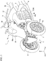
FIG. 1 is a perspective view seen from the front side of a vehicle body front section of a saddle riding vehicle according to an embodiment. -
FIG. 2 is a left side view of the vehicle body front section of the saddle riding vehicle. -
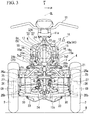
FIG. 3 is a front view of the vehicle body front section of the saddle riding vehicle. -
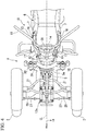
FIG. 4 is a plan view of the vehicle body front section of the saddle riding vehicle. -
FIG. 5 is a perspective view seen from the back side of the vehicle body front section of the saddle riding vehicle. -
FIG. 6 is a left side view of surroundings of a steering post, a rocking lock mechanism and a lock operation lever of the saddle riding vehicle. -
FIG. 7 is a front view of surroundings of the steering post, the rocking lock mechanism and the lock operation lever of the saddle riding vehicle. -
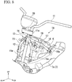
FIG. 8 is a perspective view of surroundings of the steering post of the saddle riding vehicle. -
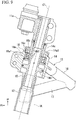
FIG. 9 is a cross-sectional view of a lateral center of the steering post of the saddle riding vehicle. - Hereinafter, an embodiment of the present invention will be described on the basis of the accompanying drawings. Further, directions of forward, rearward, leftward, rightward, and the like shown below are the same as directions in a vehicle described below unless the context clearly indicates otherwise. In addition, in appropriate places in the drawings used in the following description, an arrow FR showing a forward direction with respect to a vehicle, an arrow LH showing a leftward direction with respect to the vehicle and an arrow UP showing an upward direction with respect to the vehicle are provided.
-
FIG. 1 shows a vehicle body front section of a saddle riding vehicle 1 of the embodiment. The saddle riding vehicle 1 includes a pair of left and right front wheels (steered wheels) 2 installed on the vehicle body front section in lateral symmetry and a rear wheel (not shown) installed on a vehicle body rear section as a single driving wheel. The saddle riding vehicle 1 is configured as a two-front-wheeled type three-wheeled rocking vehicle that enables lateral rocking (rolling motion) of avehicle body 1A in a state in which the left and rightfront wheels 2 are in contact with the ground. The saddle riding vehicle 1 of the embodiment includes a structure ofrocking controller 100 having arocking lock mechanism 32A which will be described below. - In the following description, a configuration when the vehicle is in a state in which the left and right
front wheels 2 are in contact with the ground on a horizontal road surface R, a load corresponding to a vehicle weight is applied to a two-front-wheeled suspension system 4 (to be described below) in a state of 1 G, thevehicle body 1A stands upright at a lateral rocking angle of 0 degrees, and a steered angle of the left and rightfront wheels 2 is an advancing straight ahead steering state of 0° will be described unless the context indicates otherwise. In the description as given below, lateral symmetry with respect to a vehicle body lateral center is formed unless the context indicates otherwise. - Referring to
FIG. 2 , in the saddle riding vehicle 1, a frontsuspension frame body 5 of the two-front-wheeled suspension system 4 is integrally coupled to a front section of amain frame body 6 disposed at a center of the vehicle body. A rear wheel suspension system (not shown) is connected to a rear section of themain frame body 6. Themain frame body 6 is formed in a cradle shape that surrounds apower unit 3A of the saddle riding vehicle 1, and obtained by integrally coupling a plurality types of metal material through welding or the like. For example, thepower unit 3A includes a horizontallyopposed engine 3. - Referring to
FIG. 5 , themain frame body 6 includes a pair of left and rightmain frames 7 extending in a forward/rearward direction of the vehicle and bent in an inverted V shape when seen in a side view, a pair of left andright pivot frames 8 extending downward to be connected torear sections 7b of the left and rightmain frames 7, and a pair of left and right downframes 9 extending downward from front end portions of the left and rightmain frames 7 and then extending to be bent rearward and connected to front sides of lower sections of the left andright pivot frames 8. Themain frame body 6 includes a cross frame configured to connect the left and right frame members at an appropriate place. - Referring to
FIG. 1 andFIG. 6 , afuel tank 37 for theengine 3 is disposed above the left and rightmain frames 7. Aseat 36 on which an occupant sits is disposed behind thefuel tank 37. A pair of left andright radiators 40 are disposed on left and right outer sides offront sections 7a of the left and rightmain frames 7. Surroundings of the left andright radiators 40 are covered by a pair of left andright radiator shrouds 40a. The left andright radiator shrouds 40a extends to a front side of the vehicle beyond thefuel tank 37 and front end positions of the left and rightmain frames 7. - Referring to
FIG. 2 to FIG. 5 , asteering post 13 configured to support an upper section of asteering shaft 12 is attached to a front upper section of themain frame body 6. A bartype steering handle 11 is attached to an upper end portion of thesteering shaft 12 via ahandle post 11a above thesteering post 13. A lower section of thesteering shaft 12 is pivotably supported by a rear section of the frontsuspension frame body 5. A line CL in the drawings designates a lateral center of thevehicle body 1A (a vehicle body lateral center). - A central axis (a steering axis) C1 of the
steering shaft 12 is disposed on a vehicle body lateral center CL. The steering axis C1 is inclined such that an upper side in a vertical direction is disposed on a rear side when seen in a side view. Thesteering shaft 12 is disposed to overlap the front end portions of themain frames 7 when seen in a side view. While thesteering shaft 12 integrally extends from thehandle post 11a into the rear section of the frontsuspension frame body 5, thesteering shaft 12 is not limited to an integrated member and may be configured to integrally pivot even if thesteering shaft 12 is divided in the middle. - The
steering post 13 is provided in a state in which a cylindrical shaft holder 14 through which thesteering shaft 12 is inserted is supported by a pair of left and rightfront columns 15 and a pair of left and rightrear columns 16. Theshaft holder 14 is disposed in a direction in which therear sections 7b inclined forward and upward in the left and rightmain frames 7 is extended when seen in a side view. Thefront sections 7a of the left and rightmain frames 7 are inclined forward and downward, and a height of themain frame body 6 is restricted. - Referring to
FIG. 1 ,FIG. 6 andFIG. 7 , an upper rear portion and side portions of the steeringpost 13 are covered by the front section of thefuel tank 37 and the left and right radiator shrouds 40a. A front side of the steeringpost 13 is covered by afront cover 38. Aheadlight 38a is disposed on the upper section of thefront cover 38. Ameter device 39 is supported by thehandle post 11a on an upper rear side of thefront cover 38. A brake lever 11b is disposed in front of a right grip of thesteering handle 11, and aclutch lever 11c is disposed in front of a left grip of thesteering handle 11. The brake lever 11b is at least one operator for front and rear wheel brakes, and theclutch lever 11c is an operator for a transmission clutch between theengine 3 and a gearbox (not shown) in thepower unit 3A. A frontlower cover 20 extending in the upward/downward direction is attached to the front end portion of the frontsuspension frame body 5. - Referring to
FIG. 2 to FIG. 5 , the two-front-wheeledsuspension system 4 has an aspect of a double wishbone configured to independently suspend the left and rightfront wheels 2 on both sides of the frontsuspension frame body 5. Suspension components such as the frontsuspension frame body 5 of the two-front-wheeledsuspension system 4, left and rightupper arms 21,lower arms 23,cushion units 30, and so on, are disposed generally below extension lines 7a1' of upper surfaces 7a1 of thefront sections 7a of the left and rightmain frames 7 when seen in a side view. Accordingly, a height of the suspension components of the two-front-wheeledsuspension system 4 is restricted, and such disposition contributes to lowering of a center of gravity of the saddle riding vehicle 1. - Front end portions of the left and right
main frames 7 are bent inward in the vehicle width direction and are integrally joined to each other. The frontsuspension frame body 5 is fastened and fixed to the front end portions of the left and rightmain frames 7 and the left and right down frames 9. A rear wheel suspension system (not shown) is connected to the rear section of themain frame body 6 including the left and right pivot frames 8. - In the two-front-wheeled
suspension system 4, in a state in which the left and rightfront wheels 2 are in contact with the ground, thevehicle body 1A including themain frame body 6, thepower unit 3A, the frontsuspension frame body 5, and so on, can be laterally rocked, and the left and rightfront wheels 2 can be similarly laterally rocked according to the lateral rocking of thevehicle body 1A. On the other hand, the two-front-wheeledsuspension system 4 enables the left and rightfront wheels 2 to alternately vertically move with respect to thevehicle body 1A. - Referring to
FIG. 2 to FIG. 5 , the frontsuspension frame body 5 extends in front of themain frame body 6 at a center in the vehicle width direction.Outer link members 25 are supported on left and right sides of the frontsuspension frame body 5 via theupper arms 21 and thelower arms 23. Left andright knuckle members 26 and the left and rightfront wheels 2 are steerably supported by the left and rightouter link members 25. - The inner end portions disposed at centers of the left and right
upper arms 21 in the vehicle width direction are vertically rockably supported by the upper section of the frontsuspension frame body 5 via anupper rocking shaft 22 extending generally in a forward/rearward direction. The inner end portions disposed at the centers of the left and rightlower arms 23 in the vehicle width direction are vertically rockably supported by the lower section of the frontsuspension frame body 5 via alower rocking shaft 24 parallel to theupper rocking shaft 22. Axes C2 and C3 of the upper andlower rocking shafts shaft 12. - The upper end portions of the left and right
outer link members 25 are rockably supported by the outer end portions of the left and rightupper arms 21 via upperouter rocking shafts 25a parallel to the upper andlower rocking shafts outer link members 25 are rockably supported by the outer end portions of the left and rightlower arms 23 via lowerouter rocking shafts 25b parallel to the upper andlower rocking shafts - When seen in the axial direction of the upper and
lower rocking shafts upper arms 21, the left and rightlower arms 23 and the left and rightouter link members 25 are disposed in a parallel link shape on left and right sides of the vehicle body. Accordingly, when the left and rightupper arms 21 and the left and rightlower arms 23 vertically rock, the left and rightouter link members 25 vertically move substantially parallel to each other, and the left andright knuckle members 26 and the left and rightfront wheels 2 vertically move substantially parallel to each other together with the left and rightouter link members 25. The upper andlower rocking shafts vehicle body 1A. - Here, a
steering link mechanism 12c is connected to a lower end portion of the steeringshaft 12. The left andright knuckle members 26 are connected to thesteering link mechanism 12c via left andright tie rods 27. The left and rightfront wheels 2 are rotatably and axially supported by the left andright knuckle members 26. Pivotal movement of the steering handle 11 and steering of the left and rightfront wheels 2 are linked via the steeringshaft 12, thesteering link mechanism 12c, the left andright tie rods 27 and the left andright knuckle members 26. - Referring to
FIG. 2 to FIG. 5 , when seen in the axial direction of the upper andlower rocking shafts right tie rods 27 are installed to be substantially parallel to and have substantially the same length as those of the left and rightupper arms 21 and the left and rightlower arms 23. That is, when seen in the axial direction of the upper andlower rocking shafts right tie rods 27, the left and rightupper arms 21 and the left and rightlower arms 23 are disposed in a parallel link shape on left and right sides of the vehicle body. Accordingly, when the left and rightupper arms 21 and the left and rightlower arms 23 vertically lock, the left andright tie rods 27 vertically rock substantially parallel to the left and rightupper arms 21 and the left and rightlower arms 23, and an influence on a steering angle of the left and rightfront wheels 2 is minimized. - The left and
right cushion units 30 configured to receive loads to the left and rightfront wheels 2 extend generally in the upward/downward direction at above the rear sections of the left and rightlower arms 23. The left andright cushion units 30 are inclined such that upper sides thereof in the vertical direction are disposed on a rear side, and are disposed to extend to be perpendicular to the upper andlower rocking shafts right cushion units 30 are disposed to extend substantially vertically when seen in a front view. - The left and
right cushion units 30 have lower end portions thereof connected to the left and rightlower arms 23, and upper end portions thereof connected to left and right end portions of cushion support arms 29 (arm member), respectively. The left and right central portions of thecushion support arms 29 are rockably supported by the frontsuspension frame body 5 via rockingshafts 29a parallel to the upper andlower rocking shafts vehicle body 1A is connected to thecushion support arms 29 via link members 44 (seeFIG. 6 andFIG. 7 ). - The
cushion support arms 29 integrally have left andright arm sections 29b. The left andright arm sections 29b are disposed in a parallel link form on left and right sides of the vehicle body together with the left and rightlower arms 23 and the left andright cushion units 30 when seen in the axial direction of the upper andlower rocking shafts right arm sections 29b and the left and rightlower arms 23 vertically rock, the left andright cushion units 30 vertically rock substantially parallel thereto. - The
outer link members 25 extend generally in the upward/downward direction, andsupport knuckle members 26 on the outer sides of the lower sections thereof. Theknuckle members 26 steerably support steering axles (king pin shafts) substantially parallel to the steeringshaft 12 when seen in a side view. Hubs (not shown) of thefront wheels 2 are rotatably supported by theknuckle members 26 viaaxles 28.Wheels 2a of thefront wheels 2 are fastened and fixed to the hubs by a plurality offastening sections 2b. Front wheel brakes (not shown) are provided inside thewheels 2a. - Central axes (king pin axes) C9 of the left and right steering axles are disposed on vertical lines offset equidistantly from the vehicle body lateral center CL to left and right sides when seen in a front view. The king pin axes C9 are disposed to be inclined such that upper sides are disposed on rear sides when seen in a side view. An intersection T1' of a downward extension portion of a king pin axis C9 with the road surface R when seen in the side view is disposed in front of a ground-contact point T1 vertically below an axle center C5 of the
front wheels 2 to generate a trail. An inclination angle of the king pin axes C9 in the vertical direction is a caster angle when seen in a side view. Theaxles 28 of thefront wheels 2 are offset toward front sides of the king pin axes C9 when seen in a side view. - Referring to
FIG. 6 andFIG. 7 , alock plate 31 having an arc-shapedsection 31a about the rockingshafts 29a of thecushion support arms 29 is fixed to upper sections of thecushion support arms 29. Thelock plate 31 is formed in a plate shape which crosses with the axial direction of the upper andlower rocking shafts lock plate 31 is formed in a plate shape perpendicular to the axial direction of the upper andlower rocking shafts lock plate 31 has left andright leg sections 31b extending downward from both of left and right end portions of the arc-shapedsection 31a curved to protrude upward. The lower end portions of the left andright leg sections 31b are fastened and fixed to the upper section of the left andright arm sections 29b of thecushion support arms 29, respectively. - A
lock caliper 32 that can clamp the arc-shapedsection 31a in a thickness direction is disposed on the upper end position of the arc-shapedsection 31a. Thelock caliper 32 is fastened to and supported by the steeringpost 13 via acaliper stay 33 in the leftward/rightward direction. Thelock plate 31 and thelock caliper 32 constitute the rockinglock mechanism 32A configured to lock the lateral rocking of thevehicle body 1A. - When the
vehicle body 1A is in an upright state in which the lateral rocking angle is 0 degrees, thelock caliper 32 is disposed on the upper end position of the arc-shapedsection 31a. When thelock caliper 32 clamps thelock plate 31 in this state, the lateral rocking of thevehicle body 1A is locked in the upright state. - When the
vehicle body 1A is laterally rocked, while thelock caliper 32 is laterally rocked together with thevehicle body 1A, thelock plate 31 moves parallel to thecushion support arms 29 in a horizontal posture. Thelock caliper 32 relatively rocks with respect to thelock plate 31 along the arc-shapedsection 31a. When thelock caliper 32 clamps thelock plate 31 in this state, the lateral rocking of thevehicle body 1A is locked at an arbitrary rocking angle. In this case, thevehicle body 1A can be raised in the upright state even on an inclined surface. - Referring to
FIG. 1 ,FIG. 6 andFIG. 7 , for example, the lock operation mechanism 34 configured to perform a lock operation and a lock release operation of the rockinglock mechanism 32A is disposed on the left side of the vehicle body front section. The lock operation mechanism 34 is disposed close to a rear upper side of thelock caliper 32 when seen in a side view. The lock operation mechanism 34 includes abase member 34a fixed to thesteering post 13, and alock operation lever 34b rockably supported by thebase member 34a via a rockingshaft 34c in the vehicle width direction. - A
cable locking member 34d is integrally rockably connected to thelock operation lever 34b. One end of anoperation cable 35 is locked to thecable locking member 34d. The other end of theoperation cable 35 is locked to an actuating arm (not shown) of thelock caliper 32. Although thelock caliper 32 is biased to a side on which the internal mechanism releases the clamp of thelock plate 31, when theoperation cable 35 is pulled, thelock caliper 32 is operated to clamp thelock plate 31 against the biasing force. - The
lock operation lever 34b shown by a solid line inFIG. 6 shows a state of an initial position at which a clamping operation of thelock caliper 32 is released without pulling theoperation cable 35. Thelock operation lever 34b shown by a dotted-dashed line inFIG. 6 shows a state of an operation position at which thelock caliper 32 is clamped by pulling theoperation cable 35. - For example, the
lock operation lever 34b pulls theoperation cable 35 and clamps (locks) thelock caliper 32 when an operation of pivoting upward and rearward agripping section 34e that is an operation input section (a lock operation) is performed from the state of the initial position. Here, the lateral rocking of thevehicle body 1A is locked (restrained). Thelock operation lever 34b releases the clamping operation of the lock caliper 32 (a lock release action) with a termination of pulling theoperation cable 35 when an operation of pivoting thegripping section 34e downward and forward (an operation of returning thegripping section 34e to the initial position, a lock release operation) is performed by a lock operation from the state of the operation position. Here, the lock of the lateral rocking of thevehicle body 1A is released. - Since both of the
lock operation lever 34b and thelock caliper 32 are supported by the steeringpost 13 of thevehicle body 1A such that a relative position therebetween is not varied, a degree of routing freedom of theoperation cable 35 is high. That is, in the embodiment, in comparison with the case in which thelock operation lever 34b is supported by the steering handle 11 or the like and the relative position is varied, there is no need to consider a surplus length of theoperation cable 35 according to the variation of the relative position. Further, thelock operation lever 34b and thelock caliper 32 may be linked via a link mechanism, a cam mechanism, or the like, in addition to theoperation cable 35. - The
gripping section 34e of thelock operation lever 34b is disposed in front of the shaft holder 14 (in front of the axis C1 of the steering shaft 12) and disposed behind theheadlight 38a at both of the initial position and operation position. At least a portion of thegripping section 34e is disposed above theshaft holder 14 in the upward/downward direction at both of the initial position and the pivot position. Since thegripping section 34e is disposed in front of the rear end of theshaft holder 14 even upon a maximum pivotal movement, interference of thegripping section 34e with another member or an occupant during driving is suppressed. - The
gripping section 34e of thelock operation lever 34b is disposed between the front end portion of thefuel tank 37 and the rear end portion of thefront cover 38. The lock operation mechanism 34 is covered by aradiator shroud 40a from the outside in the vehicle width direction except for surroundings of thegripping section 34e of thelock operation lever 34b. Since thegripping section 34e of thelock operation lever 34b is disposed in front of thefuel tank 37 gripped by an occupant's knees and disposed to be separated forward and downward from the steering handle 11 while being disposed at a position where thegripping section 34e is easily seen from the occupant and easily operated, an unintentional contact of the occupant with thelock operation lever 34b is suppressed. - Referring to
FIG. 6 andFIG. 7 , theactuator 41 includes a bottomedcylindrical housing 42 parallel to the upper andlower rocking shafts rotating drive shaft 41a coaxial with thehousing 42. Theactuator 41 is an electric motor or a fluidic device configured to generate a torque around a central axis C7 in therotating drive shaft 41a. Amotor 42a (a rotating electric machine) including a stator and a rotor is accommodated in thehousing 42. Rockingarms 43 protruding toward both of left and right sides and configured to rock around the axis C7 are installed on the rear section of theactuator 41. The rockingarms 43 are connected to therotating drive shaft 41a protruding toward a rear side of thehousing 42 via a connectingapparatus 45. The rockingarms 43 are connected to the left andright arm sections 29b of thecushion support arms 29 via thelink members 44 extending in the upward/downward direction. The rockingarms 43, thelink members 44 and thecushion support arms 29 are disposed in a parallel link shape when seen in the axial direction of the upper andlower rocking shafts - A lower side of the rear end portion of the
housing 42 of theactuator 41 is fixed to anactuator support section 5a of the frontsuspension frame body 5. Acowl stay 5b configured to support thefront cover 38 or the like is bridged between the rear upper end portion of thehousing 42 of theactuator 41 and the front end portion of theshaft holder 14 of the steeringpost 13. - The connecting
apparatus 45 configured to connect the rockingarms 43 and therotating drive shaft 41a is installed on the rear end portion of theactuator 41. The connectingapparatus 45 is disposed to enter the inner circumferential region of thelock plate 31 of the rockinglock mechanism 32A together with therotating drive shaft 41a protruding rearward from thehousing 42. - The connecting
apparatus 45 accommodates a load sensor configured to detect a load (a torque) transmitted between the rockingarms 43 and therotating drive shaft 41a. That is, the connectingapparatus 45 functions as a torque detecting sensor configured to detect a transmission torque between the rockingarms 43 and therotating drive shaft 41a. Therotating drive shaft 41a of theactuator 41 protrudes rearward from the vehicle body through the inner circumferential region of thelock plate 31 and is connected to the load sensor. Therotating drive shaft 41a of theactuator 41 is arranged so as to penetrate an inner circumferential region of thelock plate 31. At least a part of theactuator 41 overlaps with thelock plate 31 in the forward/rearward direction. A detected value of the load is input to an electronic control unit (ECU) 46 serving as a control unit configured to control an actuation of theactuator 41. TheECU 46 controls driving of theactuator 41 on the basis of a detection result of the connectingapparatus 45, a vehicle speed, an inclination of the vehicle, an operation amount of a rider, or the like. - A load around the central axis C7 generated between the rocking
arms 43 and therotating drive shaft 41a is generated according to an operation resistance (a torque) of theactuator 41 when thecushion support arms 29 are to rock with respect to theactuator 41 supported at thevehicle body 1A side. That is, a load around the central axis C7 is generated between the rockingarms 43 and therotating drive shaft 41a upon lateral rocking of thevehicle body 1A according to the operation resistance of theactuator 41. TheECU 46 controls driving of theactuator 41 according to the detected value of the load. TheECU 46 controls theactuator 41 such that at least a load input from the rockingarms 43 to therotating drive shaft 41a, i.e., a load input from thecushion support arms 29 to theactuator 41 among the load transmitted between the rockingarms 43 and therotating drive shaft 41a is increased or decreased. A rocking center (the axis C7) of the rockingarms 43 of theactuator 41 and a rocking center (an axis C8) of thecushion support arms 29 are parallel to each other, and an interlocking mechanism of those is simplified. - The
ECU 46 detects a moment in a falling direction and a raising direction applied to thevehicle body 1A according to, for example, a detected value of an inertial sensor or a vehicle speed sensor installed on thevehicle body 1A and controls the driving of theactuator 41 such that the moment is not excessively increased. Accordingly, lateral rocking of thevehicle body 1A with respect to the driving of the occupant is assisted or suppressed, and a light rolling motion and balancing easiness are compatible. - Further, for example, the
ECU 46 controls driving of theactuator 41 such that a resistance against the rocking of thevehicle body 1A is increased when the saddle riding vehicle 1 is in a stop state or a low vehicle speed state, and controls driving of theactuator 41 such that a resistance with respect to the rocking of thevehicle body 1A is decreased when the saddle riding vehicle 1 is in a middle or high vehicle speed state. - Referring to
FIG. 2 andFIG. 8 , the steeringpost 13 is formed separately from themain frame body 6 and attached to the upper surfaces 7a1 of thefront sections 7a of the left and rightmain frames 7 of themain frame body 6. The steeringpost 13 is obtained integrally coupling a plurality of metal members through welding, fastening, or the like. The steering post 13 integrally has the plurality ofcolumns shaft holder 14 supported by the upper end portions of the plurality ofcolumns columns front sections 7a of the left and rightmain frames 7, and are set to intersect each other at the outer circumference of thecylindrical shaft holder 14 to support theshaft holder 14. The steeringpost 13 can achieve reduction in weight by lowering strength and rigidity because a load from the two-front-wheeledsuspension system 4 and rear wheel suspension system is not input. As thesteering post 13 disposed above themain frame body 6 is reduced in weight, further lowering of a center of gravity can be achieved. - The
columns front columns 15 and the pair of left and rightrear columns 16. A pair of left andright gusset pipes 17 is bridged between the upper sections of the left and right front andrear columns front columns 15 is smaller than a distance between the left and rightrear columns 16, and corresponds to that thefront sections 7a of the left and rightmain frames 7 are formed to approach each other as they go forward. Thefront columns 15 are disposed with an inclination closer to a vertical direction than that of the steering shaft 12 (and the shaft holder 14) when seen in the side view. That is, when seen in the side view, an angle of thefront columns 15 with respect to the vertical direction is smaller than angle of the steering shaft 12 (and the shaft holder 14) with respect to the vertical direction. Thefront columns 15 overlap the position in the forward/rearward direction with the axis C1 of the steering shaft 12 (that is an axis of the shaft holder 14). Accordingly, the steeringshaft 12 does not enter a space K surrounded by the front andrear columns front columns 15 may be disposed to be positioned behind the axis C1 of the steeringshaft 12. -
Lower end portions rear columns front sections 7a of the left and rightmain frames 7 by fastening bolts inserted therethrough from the outside in the vehicle width direction. That is, the steeringpost 13 is detachably attached to themain frame body 6. At least fastened positions of thelower end portions 15a of thefront columns 15 are disposed in front of the vertical line VL dropping from a center of the shaft holder 14 (a center of a width in the axial direction on the axis C1) when seen in the side view, and at least fastened positions oflower end portions 16a of therear columns 16 are disposed behind the vertical line VL when seen in the side view. Thelower end portions 15a of thefront columns 15 are disposed at left and right outer sides further than the vehicle body lateral center CL, and thelower end portions 16a of therear columns 16 are disposed at left and right outer sides further than the vehicle body lateral center CL. Accordingly, the plurality ofcolumns shaft holder 14 so as to be broaden towards the bottom, and theshaft holder 14 can be supported at front, rear, left and right sides with good balance. - An air
cleaner box 19 for engine intake is disposed in the space K inside the steeringpost 13. Since the steeringshaft 12 is not disposed in the space K inside the steeringpost 13, presence of the steeringshaft 12 does not exert an influence on a capacity of theair cleaner box 19. Accordingly, the capacity of theair cleaner box 19 can be increased as possible while disposing theair cleaner box 19 inside the steeringpost 13. Since thesteering post 13 is detachable, assemblability or maintenance of theair cleaner box 19 is secured. - Referring to
FIG. 9 , theshaft holder 14 supports the steeringshaft 12 via abearing 18 that can be automatically centered. Thebearing 18 is a ball bearing, a trajectory surface 18a1 of anouter ring 18a is a spherical surface, and a center of the spherical surface coincides with a center of thebearing 18. The center of thebearing 18 is a point which is at a center of theouter ring 18a within the width in the axial direction and which is on the axis C1. Aninner ring 18b has two rows of trajectory grooves 18b1, and a plurality of bearingballs 18c are rolled along each of the trajectory grooves 18b1. Theinner ring 18b, the bearingballs 18c and a cage (not shown) configured to hold the bearingballs 18c are pivotable while being inclined with respect to theouter ring 18a within a prescribed angle. - The
outer ring 18a is fixed and held by the inner circumference of theshaft holder 14, and theinner ring 18b is fixed and held by the outer circumference of the steeringshaft 12. Even when a deviation of a shaft center occurs between theshaft holder 14 and the steeringshaft 12 in the configuration, the deviation of the shaft center of the outer andinner rings shaft holder 14 and the steeringshaft 12 can be absorbed even using thesteering post 13 configured to support theshaft holder 14 in the plurality ofcolumns post 13 is detachable. Acollar 14a is interposed between theinner ring 18b and thehandle post 11a, and an umbrella part 14a1 configured to cover an upper end opening of theshaft holder 14 is formed on an outer circumference of thecollar 14a. Adust seal section 14b configured to prevent intrusion of water or foreign substances from an opening of the lower section of theshaft holder 14 is installed on the lower section inner circumference of theshaft holder 14 below thebearing 18. - Referring to
FIG. 6 andFIG. 7 , thelock caliper 32 is attached to thefront columns 15 via thecaliper stay 33. The caliper stay 33 is constituted by a belt-shaped steel member extending in the leftward/rightward direction, and bent such that left and right side portions thereof are displaced rearward with respect to left and right central portions. Thelock caliper 32 is fastened and fixed to the left and right central portions of thecaliper stay 33, and the left and right end portions of the caliper stay 33 are fastened and fixed to thefront columns 15. Thelock caliper 32 is fastened to the left and right central portions of the caliper stay 33 by fastening bolts inserted therethrough from a front side thereof, and the left and right end portions of the caliper stay 33 are fastened to thefront columns 15 by fastening bolts inserted therethrough from the outside in the vehicle width direction. - While an operation of fastening the
lock caliper 32 from the front side of the vehicle is interfered with theactuator 41, an operation of fastening a small assembly of thelock caliper 32 and the caliper stay 33 to thefront columns 15 from the outside in the vehicle width direction is easily performed because thecaliper stay 33 and fastening sections a15b of thefront columns 15 are exposed to the outside in the vehicle width direction. Accordingly, attachment workability of thelock caliper 32 can be improved. - As described above, the embodiment provides the structure of rocking controller of a saddle riding type vehicle 1 including the pair of left and right
front wheels 2, thevehicle body 1A that is laterally rockable in a state in which the pair of left and rightfront wheels 2 are in contact with a ground, and anactuator 41 configured to control the lateral rock of thevehicle body 1A, the structure of rockingcontroller 100 includes: a rockinglock mechanism 32A configured to lock lateral rocking of thevehicle body 1A; wherein the rockinglock mechanism 32A includes an arc shapedlock plate 31 which crosses with an axial direction of a rocking shaft of thevehicle body 1A and alock caliper 32 configured to lock a relative rocking between thelock plate 31 and thelock caliper 32 by clamping thelock plate 31, and amotor 42a for theactuator 41 is arranged in front of the rockinglock mechanism 32A and therotating drive shaft 41a of themotor 42a is arranged so as to penetrate an inner circumferential region of the arc shaped lock plate 31 (at least a part of theactuator 41 overlaps with thelock plate 31 in the forward/rearward direction). - According to the configuration, it is possible to avoid arranging the
actuator 41 for rocking control, which is a heavy component, in the front section as much as possible, and therefore, it is possible to achieve a concentration of the mass and to suppress theactuator 41 extending forward. - In the embodiment, the
lock plate 31 is fixed to acushion support arm 29 configured to move parallel when thevehicle body 1A is laterally rocking in left and right, and theactuator 41 includes therotating drive shaft 41a that is parallel with a rockingshaft 29a between thevehicle body 1A and thecushion support arm 29 and configured to apply a rotating drive force with respect to thecushion support arm 29. - In this case, since the direction in which the force from the
rotating drive shaft 41a of theactuator 41 is along a relative rocking direction of thecushion support arm 29 and thevehicle body 1A, it is possible to connect theactuator 41 and thecushion support arm 29 with small number of components and to perform a rocking control by efficiently applying the rotating drive force of theactuator 41 to thecushion support arm 29. - In the embodiment, the rotating
drive shaft 41a and the rockingshaft 29a is arranged to have a different axial with each other, theactuator 41 includes a rockingarm 43 integrally rotate with therotating drive shaft 41a, and the rockingarm 43 and thecushion support arm 29 is connected via alink member 44. - Accordingly, due to the present of the link member, it is possible to easily absorb a deviation of the shaft center between the
rotating drive shaft 41a and the rockingshaft 29a compared to a case therotating drive shaft 41a of theactuator 41 is arranged at a same axial with the rockingshaft 29a of thecushion support arm 29. - In the embodiment, the
actuator 41 has a torque detecting sensor (connecting apparatus 45) at a rear side thereof which is a side closer to thelock plate 31. - In this way, since the actuator has a torque detecting sensor at a rear side thereof, it is possible to easily protect the torque detecting sensor from foreign objects and the like from the front side of the vehicle. If the torque detecting sensor is arranged inside of the lock plate, it is possible to easily protect the torque detecting sensor from foreign objects and the like from the surroundings.
- Further, the present invention is not limited to the above-mentioned embodiment, and for example, the present invention may be applied to a four-wheeled vehicle including left and right front wheels and left and right rear wheels, in addition to the three-wheeled vehicle including the left and right front wheels and the single rear wheel.
- While the power unit of the embodiment includes an engine as a drive source, the drive source may be an electric motor or may be a drive source including the electric motor.
- The rotating drive shaft of the actuator and the rocking shaft of the cushion support arm may be arranged to have same axial.
- While preferred embodiments of the invention have been described and illustrated above, it should be understood that these are exemplary of the invention and are not to be considered as limiting. Additions, omissions, substitutions, and other modifications can be made without departing from the scope of the present invention. Accordingly, the invention is not to be considered as being limited by the foregoing description, and is only limited by the scope of the appended claims.
Claims (4)
- A structure of rocking controller (100) of a saddle riding type vehicle (1) including a pair of left and right front wheels (2), a vehicle body (1A) that is laterally rockable in a state in which the pair of left and right front wheels (2) are in contact with a ground, and an actuator (41) configured to control the lateral rock of the vehicle body (1A), the structure of rocking controller (100) comprising:a rocking lock mechanism (32A) configured to lock lateral rocking of the vehicle body (1A);wherein the rocking lock mechanism (32A) includes an arc shaped lock plate (31) which crosses with an axial direction of a rocking shaft of the vehicle body (1A) and a lock caliper (32) configured to lock a relative rocking between the lock plate (31) and the lock caliper (32) by clamping the lock plate (31), anda motor (42a) for the actuator (41) is arranged in front of the rocking lock mechanism (32A) and the rotating drive shaft (41a) of the motor (42a) is arranged so as to penetrate an inner circumferential region of the arc shaped lock plate (31).
- The structure of rocking controller of a saddle riding type vehicle according to claim 1,wherein the lock plate (31) is fixed to an arm member (29) configured to move parallel when the vehicle body (1A) is laterally rocking in left and right, andthe actuator (41) includes the rotating drive shaft (41a) that is parallel with a rocking shaft (29a) between the vehicle body (1A) and the arm member (29) and configured to apply a rotating drive force with respect to the arm member (29).
- The structure of rocking controller of a saddle riding type vehicle according to claim 2,wherein the rotating drive shaft (41a) and the rocking shaft (29a) are arranged to have a different axial with each other,the actuator (41) includes a rocking arm (43) integrally rotate with the rotating drive shaft (41a), andthe rocking arm (43) and the arm member (29) are connected via a link member (44).
- The structure of rocking controller of a saddle riding type vehicle according to any one of claims 1 to 3,
wherein the actuator (41) has a torque detecting sensor (45) at a rear side thereof which is a side closer to the lock plate (31).
Applications Claiming Priority (1)
| Application Number | Priority Date | Filing Date | Title |
|---|---|---|---|
| JP2017066056A JP6478233B2 (en) | 2017-03-29 | 2017-03-29 | Swing control unit structure of straddle type vehicle |
Publications (2)
| Publication Number | Publication Date |
|---|---|
| EP3381779A1 true EP3381779A1 (en) | 2018-10-03 |
| EP3381779B1 EP3381779B1 (en) | 2020-01-22 |
Family
ID=61526567
Family Applications (1)
| Application Number | Title | Priority Date | Filing Date |
|---|---|---|---|
| EP18158884.9A Active EP3381779B1 (en) | 2017-03-29 | 2018-02-27 | Structure of rocking controller of saddle riding type vehicle |
Country Status (3)
| Country | Link |
|---|---|
| US (1) | US10493813B2 (en) |
| EP (1) | EP3381779B1 (en) |
| JP (1) | JP6478233B2 (en) |
Cited By (1)
| Publication number | Priority date | Publication date | Assignee | Title |
|---|---|---|---|---|
| EP3957556A1 (en) * | 2020-07-30 | 2022-02-23 | Kawasaki Jukogyo Kabushiki Kaisha | Front two-wheeled vehicle |
Families Citing this family (4)
| Publication number | Priority date | Publication date | Assignee | Title |
|---|---|---|---|---|
| EP3375700B1 (en) * | 2015-11-13 | 2020-08-05 | Yamaha Hatsudoki Kabushiki Kaisha | Leaning vehicle |
| JP2018144698A (en) * | 2017-03-07 | 2018-09-20 | ヤマハ発動機株式会社 | vehicle |
| JP2018144697A (en) * | 2017-03-07 | 2018-09-20 | ヤマハ発動機株式会社 | vehicle |
| JP7195774B2 (en) * | 2018-06-13 | 2022-12-26 | カワサキモータース株式会社 | saddle-riding vehicle |
Citations (2)
| Publication number | Priority date | Publication date | Assignee | Title |
|---|---|---|---|---|
| EP3056418A1 (en) * | 2015-02-10 | 2016-08-17 | Honda Motor Co., Ltd. | Rolling type vehicle |
| JP2016147539A (en) | 2015-02-10 | 2016-08-18 | 本田技研工業株式会社 | Oscillation type vehicle |
Family Cites Families (21)
| Publication number | Priority date | Publication date | Assignee | Title |
|---|---|---|---|---|
| US2819093A (en) * | 1954-09-16 | 1958-01-07 | Homer E Geiser | Suspension mechanism for motor driven vehicles and the like |
| US4632413A (en) * | 1984-02-22 | 1986-12-30 | Honda Giken Kogyo Kabushiki Kaisha | Body banking suspension apparatus for a vehicle |
| JPS61110611A (en) * | 1984-11-02 | 1986-05-28 | Hiroshi Sugano | Car for inclined ground |
| WO2005075278A1 (en) * | 2004-02-06 | 2005-08-18 | Phillip Ronald James | Tilting vehicle |
| WO2007127783A1 (en) * | 2006-04-26 | 2007-11-08 | Vectrix Corporation | Vehicle with lockable tilt system |
| FR2961783B1 (en) * | 2010-06-23 | 2012-08-03 | Veleance | DEVICE FOR MONITORING THE INCLINATION OF A FRAME MOUNTED ON A RECLINING BEARING TRAIN |
| TWI399310B (en) * | 2010-07-06 | 2013-06-21 | Kwang Yang Motor Co | A steering device for two front wheel vehicles |
| CN202414056U (en) * | 2012-01-14 | 2012-09-05 | 于金君 | Inverted motor tricycle capable of tilting tricycle body |
| US8596660B2 (en) * | 2012-01-18 | 2013-12-03 | National Taiwan University Of Science And Technology | Three-wheeled motor vehicle with high safety |
| FR3010042B1 (en) * | 2013-09-02 | 2015-08-14 | Bruno Malphettes | THREE-WHEEL RECLINING VEHICLE |
| JP2015127183A (en) * | 2013-12-27 | 2015-07-09 | 本田技研工業株式会社 | Oscillation type vehicle |
| JP6256922B2 (en) * | 2015-02-10 | 2018-01-10 | 本田技研工業株式会社 | Swing type vehicle |
| JP6134362B2 (en) * | 2015-09-18 | 2017-05-24 | 本田技研工業株式会社 | Vehicle suspension lock mechanism |
| CA3005807A1 (en) * | 2015-11-20 | 2017-05-26 | Yamaha Hatsudoki Kabushiki Kaisha | Leaning vehicle |
| CA3005803A1 (en) * | 2015-11-20 | 2017-05-26 | Yamaha Hatsudoki Kabushiki Kaisha | Leaning vehicle |
| CA3005823A1 (en) * | 2015-11-20 | 2017-05-26 | Yamaha Hatsudoki Kabushiki Kaisha | Leaning vehicle |
| JP6469060B2 (en) * | 2016-09-29 | 2019-02-13 | 本田技研工業株式会社 | Swing control device for front two-wheel swing vehicle |
| JP6393932B2 (en) * | 2016-09-29 | 2018-09-26 | 本田技研工業株式会社 | Swing control device for front two-wheel swing vehicle |
| JP6525215B2 (en) * | 2017-03-29 | 2019-06-05 | 本田技研工業株式会社 | Frame structure of straddle type vehicle |
| JP6547194B2 (en) * | 2017-03-29 | 2019-07-24 | 本田技研工業株式会社 | Swing lock operation part structure of saddle-ride type vehicle |
| WO2019099730A1 (en) * | 2017-11-15 | 2019-05-23 | Future Motion, Inc. | Control system for a tiltable vehicle |
-
2017
- 2017-03-29 JP JP2017066056A patent/JP6478233B2/en active Active
-
2018
- 2018-02-27 US US15/906,050 patent/US10493813B2/en active Active
- 2018-02-27 EP EP18158884.9A patent/EP3381779B1/en active Active
Patent Citations (2)
| Publication number | Priority date | Publication date | Assignee | Title |
|---|---|---|---|---|
| EP3056418A1 (en) * | 2015-02-10 | 2016-08-17 | Honda Motor Co., Ltd. | Rolling type vehicle |
| JP2016147539A (en) | 2015-02-10 | 2016-08-18 | 本田技研工業株式会社 | Oscillation type vehicle |
Cited By (1)
| Publication number | Priority date | Publication date | Assignee | Title |
|---|---|---|---|---|
| EP3957556A1 (en) * | 2020-07-30 | 2022-02-23 | Kawasaki Jukogyo Kabushiki Kaisha | Front two-wheeled vehicle |
Also Published As
| Publication number | Publication date |
|---|---|
| JP2018167677A (en) | 2018-11-01 |
| US10493813B2 (en) | 2019-12-03 |
| JP6478233B2 (en) | 2019-03-06 |
| US20180281546A1 (en) | 2018-10-04 |
| EP3381779B1 (en) | 2020-01-22 |
Similar Documents
| Publication | Publication Date | Title |
|---|---|---|
| EP3381778B1 (en) | Structure of rocking lock operation part of saddle riding type vehicle | |
| EP3381779B1 (en) | Structure of rocking controller of saddle riding type vehicle | |
| US10894571B2 (en) | Leaning vehicle | |
| US10994796B2 (en) | Leaning vehicle | |
| US10167043B2 (en) | Vehicle | |
| JP6233972B2 (en) | Front suspension structure for saddle-ride type vehicles | |
| EP3381782B1 (en) | Frame structure of saddle riding type vehicle | |
| JP2018127158A (en) | Front two-wheel suspension system | |
| JP4607643B2 (en) | Saddle riding vehicle | |
| TWI714242B (en) | Tilting vehicle | |
| JP4558432B2 (en) | Swing arm structure | |
| JP2006256579A (en) | Electric power steering device for rough terrain vehicle | |
| JP2011042225A (en) | Tricycle | |
| JP5122537B2 (en) | Front wheel steering device and tricycle | |
| JP2017047764A (en) | Saddle-riding type vehicle | |
| JP6241747B2 (en) | Front two-wheel saddle-type swing vehicle | |
| JP6288647B2 (en) | Front two-wheel saddle-type swing vehicle | |
| JP6201188B2 (en) | Steering structure for saddle-ride type vehicles | |
| CN102167121B (en) | Saddle type vehicle | |
| CN114981100A (en) | Front suspension assembly for vehicle | |
| JP2006281853A (en) | Vehicle braking device | |
| JP7149125B2 (en) | Straddle vehicle | |
| JP2007176387A (en) | Front wheel steering device of motorcycle | |
| JPH05105169A (en) | Front wheel suspension system for motorcycles |
Legal Events
| Date | Code | Title | Description |
|---|---|---|---|
| PUAI | Public reference made under article 153(3) epc to a published international application that has entered the european phase |
Free format text: ORIGINAL CODE: 0009012 |
|
| STAA | Information on the status of an ep patent application or granted ep patent |
Free format text: STATUS: REQUEST FOR EXAMINATION WAS MADE |
|
| 17P | Request for examination filed |
Effective date: 20180227 |
|
| AK | Designated contracting states |
Kind code of ref document: A1 Designated state(s): AL AT BE BG CH CY CZ DE DK EE ES FI FR GB GR HR HU IE IS IT LI LT LU LV MC MK MT NL NO PL PT RO RS SE SI SK SM TR |
|
| AX | Request for extension of the european patent |
Extension state: BA ME |
|
| RBV | Designated contracting states (corrected) |
Designated state(s): AL AT BE BG CH CY CZ DE DK EE ES FI FR GB GR HR HU IE IS IT LI LT LU LV MC MK MT NL NO PL PT RO RS SE SI SK SM TR |
|
| GRAP | Despatch of communication of intention to grant a patent |
Free format text: ORIGINAL CODE: EPIDOSNIGR1 |
|
| STAA | Information on the status of an ep patent application or granted ep patent |
Free format text: STATUS: GRANT OF PATENT IS INTENDED |
|
| INTG | Intention to grant announced |
Effective date: 20190806 |
|
| GRAS | Grant fee paid |
Free format text: ORIGINAL CODE: EPIDOSNIGR3 |
|
| GRAA | (expected) grant |
Free format text: ORIGINAL CODE: 0009210 |
|
| STAA | Information on the status of an ep patent application or granted ep patent |
Free format text: STATUS: THE PATENT HAS BEEN GRANTED |
|
| AK | Designated contracting states |
Kind code of ref document: B1 Designated state(s): AL AT BE BG CH CY CZ DE DK EE ES FI FR GB GR HR HU IE IS IT LI LT LU LV MC MK MT NL NO PL PT RO RS SE SI SK SM TR |
|
| REG | Reference to a national code |
Ref country code: GB Ref legal event code: FG4D |
|
| REG | Reference to a national code |
Ref country code: CH Ref legal event code: EP |
|
| REG | Reference to a national code |
Ref country code: AT Ref legal event code: REF Ref document number: 1226749 Country of ref document: AT Kind code of ref document: T Effective date: 20200215 |
|
| REG | Reference to a national code |
Ref country code: IE Ref legal event code: FG4D |
|
| REG | Reference to a national code |
Ref country code: DE Ref legal event code: R096 Ref document number: 602018002055 Country of ref document: DE |
|
| REG | Reference to a national code |
Ref country code: NL Ref legal event code: MP Effective date: 20200122 |
|
| REG | Reference to a national code |
Ref country code: LT Ref legal event code: MG4D |
|
| PG25 | Lapsed in a contracting state [announced via postgrant information from national office to epo] |
Ref country code: FI Free format text: LAPSE BECAUSE OF FAILURE TO SUBMIT A TRANSLATION OF THE DESCRIPTION OR TO PAY THE FEE WITHIN THE PRESCRIBED TIME-LIMIT Effective date: 20200122 Ref country code: NO Free format text: LAPSE BECAUSE OF FAILURE TO SUBMIT A TRANSLATION OF THE DESCRIPTION OR TO PAY THE FEE WITHIN THE PRESCRIBED TIME-LIMIT Effective date: 20200422 Ref country code: RS Free format text: LAPSE BECAUSE OF FAILURE TO SUBMIT A TRANSLATION OF THE DESCRIPTION OR TO PAY THE FEE WITHIN THE PRESCRIBED TIME-LIMIT Effective date: 20200122 Ref country code: NL Free format text: LAPSE BECAUSE OF FAILURE TO SUBMIT A TRANSLATION OF THE DESCRIPTION OR TO PAY THE FEE WITHIN THE PRESCRIBED TIME-LIMIT Effective date: 20200122 Ref country code: PT Free format text: LAPSE BECAUSE OF FAILURE TO SUBMIT A TRANSLATION OF THE DESCRIPTION OR TO PAY THE FEE WITHIN THE PRESCRIBED TIME-LIMIT Effective date: 20200614 |
|
| PG25 | Lapsed in a contracting state [announced via postgrant information from national office to epo] |
Ref country code: BG Free format text: LAPSE BECAUSE OF FAILURE TO SUBMIT A TRANSLATION OF THE DESCRIPTION OR TO PAY THE FEE WITHIN THE PRESCRIBED TIME-LIMIT Effective date: 20200422 Ref country code: GR Free format text: LAPSE BECAUSE OF FAILURE TO SUBMIT A TRANSLATION OF THE DESCRIPTION OR TO PAY THE FEE WITHIN THE PRESCRIBED TIME-LIMIT Effective date: 20200423 Ref country code: LV Free format text: LAPSE BECAUSE OF FAILURE TO SUBMIT A TRANSLATION OF THE DESCRIPTION OR TO PAY THE FEE WITHIN THE PRESCRIBED TIME-LIMIT Effective date: 20200122 Ref country code: IS Free format text: LAPSE BECAUSE OF FAILURE TO SUBMIT A TRANSLATION OF THE DESCRIPTION OR TO PAY THE FEE WITHIN THE PRESCRIBED TIME-LIMIT Effective date: 20200522 Ref country code: SE Free format text: LAPSE BECAUSE OF FAILURE TO SUBMIT A TRANSLATION OF THE DESCRIPTION OR TO PAY THE FEE WITHIN THE PRESCRIBED TIME-LIMIT Effective date: 20200122 Ref country code: HR Free format text: LAPSE BECAUSE OF FAILURE TO SUBMIT A TRANSLATION OF THE DESCRIPTION OR TO PAY THE FEE WITHIN THE PRESCRIBED TIME-LIMIT Effective date: 20200122 |
|
| REG | Reference to a national code |
Ref country code: DE Ref legal event code: R097 Ref document number: 602018002055 Country of ref document: DE |
|
| REG | Reference to a national code |
Ref country code: BE Ref legal event code: MM Effective date: 20200229 |
|
| PG25 | Lapsed in a contracting state [announced via postgrant information from national office to epo] |
Ref country code: DK Free format text: LAPSE BECAUSE OF FAILURE TO SUBMIT A TRANSLATION OF THE DESCRIPTION OR TO PAY THE FEE WITHIN THE PRESCRIBED TIME-LIMIT Effective date: 20200122 Ref country code: LT Free format text: LAPSE BECAUSE OF FAILURE TO SUBMIT A TRANSLATION OF THE DESCRIPTION OR TO PAY THE FEE WITHIN THE PRESCRIBED TIME-LIMIT Effective date: 20200122 Ref country code: MC Free format text: LAPSE BECAUSE OF FAILURE TO SUBMIT A TRANSLATION OF THE DESCRIPTION OR TO PAY THE FEE WITHIN THE PRESCRIBED TIME-LIMIT Effective date: 20200122 Ref country code: ES Free format text: LAPSE BECAUSE OF FAILURE TO SUBMIT A TRANSLATION OF THE DESCRIPTION OR TO PAY THE FEE WITHIN THE PRESCRIBED TIME-LIMIT Effective date: 20200122 Ref country code: LU Free format text: LAPSE BECAUSE OF NON-PAYMENT OF DUE FEES Effective date: 20200227 Ref country code: CZ Free format text: LAPSE BECAUSE OF FAILURE TO SUBMIT A TRANSLATION OF THE DESCRIPTION OR TO PAY THE FEE WITHIN THE PRESCRIBED TIME-LIMIT Effective date: 20200122 Ref country code: SK Free format text: LAPSE BECAUSE OF FAILURE TO SUBMIT A TRANSLATION OF THE DESCRIPTION OR TO PAY THE FEE WITHIN THE PRESCRIBED TIME-LIMIT Effective date: 20200122 Ref country code: RO Free format text: LAPSE BECAUSE OF FAILURE TO SUBMIT A TRANSLATION OF THE DESCRIPTION OR TO PAY THE FEE WITHIN THE PRESCRIBED TIME-LIMIT Effective date: 20200122 Ref country code: EE Free format text: LAPSE BECAUSE OF FAILURE TO SUBMIT A TRANSLATION OF THE DESCRIPTION OR TO PAY THE FEE WITHIN THE PRESCRIBED TIME-LIMIT Effective date: 20200122 Ref country code: SM Free format text: LAPSE BECAUSE OF FAILURE TO SUBMIT A TRANSLATION OF THE DESCRIPTION OR TO PAY THE FEE WITHIN THE PRESCRIBED TIME-LIMIT Effective date: 20200122 |
|
| REG | Reference to a national code |
Ref country code: AT Ref legal event code: MK05 Ref document number: 1226749 Country of ref document: AT Kind code of ref document: T Effective date: 20200122 |
|
| PLBE | No opposition filed within time limit |
Free format text: ORIGINAL CODE: 0009261 |
|
| STAA | Information on the status of an ep patent application or granted ep patent |
Free format text: STATUS: NO OPPOSITION FILED WITHIN TIME LIMIT |
|
| 26N | No opposition filed |
Effective date: 20201023 |
|
| PG25 | Lapsed in a contracting state [announced via postgrant information from national office to epo] |
Ref country code: IE Free format text: LAPSE BECAUSE OF NON-PAYMENT OF DUE FEES Effective date: 20200227 Ref country code: FR Free format text: LAPSE BECAUSE OF NON-PAYMENT OF DUE FEES Effective date: 20200322 Ref country code: IT Free format text: LAPSE BECAUSE OF FAILURE TO SUBMIT A TRANSLATION OF THE DESCRIPTION OR TO PAY THE FEE WITHIN THE PRESCRIBED TIME-LIMIT Effective date: 20200122 Ref country code: AT Free format text: LAPSE BECAUSE OF FAILURE TO SUBMIT A TRANSLATION OF THE DESCRIPTION OR TO PAY THE FEE WITHIN THE PRESCRIBED TIME-LIMIT Effective date: 20200122 |
|
| PG25 | Lapsed in a contracting state [announced via postgrant information from national office to epo] |
Ref country code: SI Free format text: LAPSE BECAUSE OF FAILURE TO SUBMIT A TRANSLATION OF THE DESCRIPTION OR TO PAY THE FEE WITHIN THE PRESCRIBED TIME-LIMIT Effective date: 20200122 Ref country code: BE Free format text: LAPSE BECAUSE OF NON-PAYMENT OF DUE FEES Effective date: 20200229 Ref country code: PL Free format text: LAPSE BECAUSE OF FAILURE TO SUBMIT A TRANSLATION OF THE DESCRIPTION OR TO PAY THE FEE WITHIN THE PRESCRIBED TIME-LIMIT Effective date: 20200122 |
|
| REG | Reference to a national code |
Ref country code: DE Ref legal event code: R084 Ref document number: 602018002055 Country of ref document: DE |
|
| PG25 | Lapsed in a contracting state [announced via postgrant information from national office to epo] |
Ref country code: LI Free format text: LAPSE BECAUSE OF NON-PAYMENT OF DUE FEES Effective date: 20210228 Ref country code: CH Free format text: LAPSE BECAUSE OF NON-PAYMENT OF DUE FEES Effective date: 20210228 |
|
| PG25 | Lapsed in a contracting state [announced via postgrant information from national office to epo] |
Ref country code: TR Free format text: LAPSE BECAUSE OF FAILURE TO SUBMIT A TRANSLATION OF THE DESCRIPTION OR TO PAY THE FEE WITHIN THE PRESCRIBED TIME-LIMIT Effective date: 20200122 Ref country code: MT Free format text: LAPSE BECAUSE OF FAILURE TO SUBMIT A TRANSLATION OF THE DESCRIPTION OR TO PAY THE FEE WITHIN THE PRESCRIBED TIME-LIMIT Effective date: 20200122 Ref country code: CY Free format text: LAPSE BECAUSE OF FAILURE TO SUBMIT A TRANSLATION OF THE DESCRIPTION OR TO PAY THE FEE WITHIN THE PRESCRIBED TIME-LIMIT Effective date: 20200122 |
|
| PG25 | Lapsed in a contracting state [announced via postgrant information from national office to epo] |
Ref country code: MK Free format text: LAPSE BECAUSE OF FAILURE TO SUBMIT A TRANSLATION OF THE DESCRIPTION OR TO PAY THE FEE WITHIN THE PRESCRIBED TIME-LIMIT Effective date: 20200122 Ref country code: AL Free format text: LAPSE BECAUSE OF FAILURE TO SUBMIT A TRANSLATION OF THE DESCRIPTION OR TO PAY THE FEE WITHIN THE PRESCRIBED TIME-LIMIT Effective date: 20200122 |
|
| GBPC | Gb: european patent ceased through non-payment of renewal fee |
Effective date: 20220227 |
|
| PG25 | Lapsed in a contracting state [announced via postgrant information from national office to epo] |
Ref country code: GB Free format text: LAPSE BECAUSE OF NON-PAYMENT OF DUE FEES Effective date: 20220227 |
|
| PGFP | Annual fee paid to national office [announced via postgrant information from national office to epo] |
Ref country code: DE Payment date: 20260121 Year of fee payment: 9 |