EP3381764A1 - A displaying device - Google Patents
A displaying device Download PDFInfo
- Publication number
- EP3381764A1 EP3381764A1 EP17163873.7A EP17163873A EP3381764A1 EP 3381764 A1 EP3381764 A1 EP 3381764A1 EP 17163873 A EP17163873 A EP 17163873A EP 3381764 A1 EP3381764 A1 EP 3381764A1
- Authority
- EP
- European Patent Office
- Prior art keywords
- frame
- driver
- display
- display member
- cabin
- Prior art date
- Legal status (The legal status is an assumption and is not a legal conclusion. Google has not performed a legal analysis and makes no representation as to the accuracy of the status listed.)
- Granted
Links
Images


Classifications
-
- B—PERFORMING OPERATIONS; TRANSPORTING
- B61—RAILWAYS
- B61L—GUIDING RAILWAY TRAFFIC; ENSURING THE SAFETY OF RAILWAY TRAFFIC
- B61L15/00—Indicators provided on the vehicle or train for signalling purposes
- B61L15/0072—On-board train data handling
-
- B—PERFORMING OPERATIONS; TRANSPORTING
- B61—RAILWAYS
- B61L—GUIDING RAILWAY TRAFFIC; ENSURING THE SAFETY OF RAILWAY TRAFFIC
- B61L15/00—Indicators provided on the vehicle or train for signalling purposes
- B61L15/009—On-board display devices
-
- B—PERFORMING OPERATIONS; TRANSPORTING
- B64—AIRCRAFT; AVIATION; COSMONAUTICS
- B64D—EQUIPMENT FOR FITTING IN OR TO AIRCRAFT; FLIGHT SUITS; PARACHUTES; ARRANGEMENT OR MOUNTING OF POWER PLANTS OR PROPULSION TRANSMISSIONS IN AIRCRAFT
- B64D43/00—Arrangements or adaptations of instruments
-
- G—PHYSICS
- G06—COMPUTING OR CALCULATING; COUNTING
- G06F—ELECTRIC DIGITAL DATA PROCESSING
- G06F1/00—Details not covered by groups G06F3/00 - G06F13/00 and G06F21/00
- G06F1/16—Constructional details or arrangements
- G06F1/1601—Constructional details related to the housing of computer displays, e.g. of CRT monitors, of flat displays
-
- B—PERFORMING OPERATIONS; TRANSPORTING
- B61—RAILWAYS
- B61L—GUIDING RAILWAY TRAFFIC; ENSURING THE SAFETY OF RAILWAY TRAFFIC
- B61L27/00—Central railway traffic control systems; Trackside control; Communication systems specially adapted therefor
- B61L27/20—Trackside control of safe travel of vehicle or train, e.g. braking curve calculation
- B61L2027/202—Trackside control of safe travel of vehicle or train, e.g. braking curve calculation using European Train Control System [ETCS]
-
- G—PHYSICS
- G06—COMPUTING OR CALCULATING; COUNTING
- G06F—ELECTRIC DIGITAL DATA PROCESSING
- G06F2200/00—Indexing scheme relating to G06F1/04 - G06F1/32
- G06F2200/16—Indexing scheme relating to G06F1/16 - G06F1/18
- G06F2200/161—Indexing scheme relating to constructional details of the monitor
- G06F2200/1612—Flat panel monitor
Definitions
- the present invention relates to a device for displaying information of importance for driving a vehicle to a driver inside a driver's cabin of the vehicle, the device comprising a display arrangement with a display unit having a screen configured to display said information.
- the invention is particularly directed to such devices for displaying information to a driver of a heavy transport vehicle, such as a rail vehicle (train) or an airplane, and especially where there is limited space available for arranging such a device.
- a heavy transport vehicle such as a rail vehicle (train) or an airplane
- Rail vehicles need a speed indicator so that the driver can compare the speed allowed with the current speed.
- Rail vehicles may also have an Automatic Train Protection system (ATP), such as the European Rail Traffic Management System (ERTMS), which is an automatic supervising system handling data of importance for the traffic on a railway section on which the rail vehicle is travelling, and this system comprises a said device with a display unit in the form of a Driver's Machine Interface (DMI) arranged in the driver's cabin for displaying important information to the driver, such as current maximum allowed speed and maximum allowed speed in a very near future.
- ATP Automatic Train Protection system
- ERTMS European Rail Traffic Management System
- DMI Driver's Machine Interface
- the DMI alerts the driver and the driver has to acknowledge the warning and engage the brake.
- the DMI is also used for configuration purposes at the beginning of a trip when different data are fed into the computer of the ATP system, such as the number and types of wagons of the train to which the rail vehicle belongs and at which position of the railway track braking has to start at a given speed of the train as some example of such data.
- the speed indicator is included in the ATP system's DMI or the DMI is not part of an ATP but only display essential information like the speed. In a new rail vehicle there is usually a space reserved in the driver's cabin for the DMI.
- the object of the present invention is to provide a device of the type defined in the introduction addressing the problems mentioned above.
- the display arrangement comprises two separate display units with a screen each joined to form a display member with two screens on opposite sides thereof.
- the device further comprises a frame configured to be attached to a carrier inside a driver's cabin of the vehicle and provided with on one hand mechanical members configured to interact with mechanical members of the displaying member for removable attachment of the display member to and within the frame with a screen of an optional of said display units facing the space of the driver's cabin and on the other hand with electrical connecting members for interacting with electrical connecting members of the display member for electrical connection of the display unit with a screen facing said space when the display member is attached to and received in the frame.
- the device according to the invention provides two said display units, such as DMI's, without requiring more panel area than for one such display unit.
- the display unit in use i.e. the one arranged in the frame with the screen directed towards the driver, go down
- the display member will be removed from the frame and turned and attached to the frame again with the other display unit with the screen facing the space of the driver's cabin enabling continued driving of the vehicle, since the information of importance for driving the vehicle will still be presented to the driver.
- the entire display member may be exchanged by one functioning properly or just the defect display unit may be replaced or repaired.
- each display unit is a so called Driver's Machine Interface (DMI) configured to display important information to the driver of a heavy transport vehicle, such as a train or an airplane, so as to obtain redundancy of the operation of the DMI for such a vehicle.
- DMI Driver's Machine Interface
- the invention is particularly interesting for this application, since the space available in the driver's panel of such vehicles is limited at the same time as redundancy of such a display unit constitutes a major improvement owing to the high demand of reliability and of safe operation of such vehicles.
- "Heavy” as used here includes all types of public and other transport vehicles, also ships, but excludes private cars.
- the frame has a shape configured to fit into a cavity in the driver's panel of said vehicle and is provided with members for securing the frame in said cavity.
- the device is configured to be arranged in the driver's cabin of a rail vehicle, which constitutes an advantageous application of the present invention.
- the DMI having the screen facing the space of the driver's cabin when the display member is attached to the frame is configured to form a component of an Automatic Train Protection system (ATP) for automatic supervising the operation of the rail vehicle, such as the European Rail Traffic Management System (ERTMS).
- ATP Automatic Train Protection system
- ERTMS European Rail Traffic Management System
- the electrical connecting members of the display unit with the screen facing said space of the driver's cabin are configured to automatically establish electrical connection to corresponding electrical connecting members of said frame upon attachment of the display member to the frame. This facilitates the replacement of a defect display unit by a display unit of the display member still in good order.
- said mechanical members of the display member and the frame are designed to obtain attachment of the display member to the frame by a snap-locking action. This way of obtaining attachment of the display member to the frame enables smooth switching of the display unit to be used to display information to the driver when needed.
- the mechanical members of the display member and the frame are male members entering into engagement with female members so as to obtain said attachment.
- said mechanical members of the frame are arranged at frame parts configured to form an upper and a lower frame part extending substantially horizontally when the frame is attached to a carrier inside a said driver's cabin.
- Such positioning of the mechanical members provides for an easy attaching of the display member to the frame and releasing it therefrom by the driver.
- the display member is configured to be released from the frame by bringing said mechanical members at the upper part of the frame out of engagement with mechanical members on the display member and then tilting the display member out from the frame about an axis extending along said lower frame part.
- the electrical connecting members of the frame are configured to only establish electrical connection with the display unit having the screen thereof facing the space of the driver's cabin when the display member is attached to the frame. This is preferred, since it would make no sense to have the display unit with the screen turned away from the driver connected to the electrical system of the vehicle.
- the display units and the screens thereof have a substantially rectangular shape.
- the device may also according to another embodiment of the invention have the frame provided with at least one loudspeaker.
- the two display units of the display member are separably secured to each other, which will then make it possible to remove a defect display unit from the display member and replace it by one functioning accurately.
- the invention also relates to a use of a device according to the invention for displaying information to a driver inside a driver's cabin of a rail vehicle or an airplane.
- a device 1 for displaying information of importance for driving a rail vehicle to the driver of the vehicle is arranged inside a driver's cabin 2 of the vehicle by having a frame 3 thereof secured in a cavity of the driver's panel 4 of the vehicle.
- the frame has for this sake dimensions of a rear part 21 - see Fig. 3 - corresponding to the dimensions of such a cavity and bores 20 for securing it by suitable means to said driver's panel.
- the device 1 has a display arrangement with a display member 5 removably attached to the frame 3, and the design and function of the device will now be described while making reference to Figs. 2-5 .
- the display member 5 comprises two separate display units 6, 7 with a screen, 8, 9 each configured to display information of importance for driving the vehicle.
- the two display units are joined to form a display member 5 with the two screens 8, 9 on opposite sides thereof. "Separate” does here mean that the two display units do not share any components influencing the operation of the units.
- the frame 3 is provided with on one hand mechanical members 10, 11 configured to interact with mechanical members 12, 13 of the display member 5 for removable attachment of the display member to and within the frame with a screen of an optional of the display units facing the space of the driver's cabin and on the other hand with electrical connecting members 14 for interacting with electrical connecting members 15, 16 of the display member for electrical connection of the display unit with the screen facing the space of the driver's cabin when the display member is attached to and received in the frame as shown in Fig. 2 .
- the frame is also provided with a loudspeaker 17.
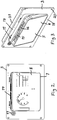
- Fig. 2 It is shown in Fig. 2 how the screen 8 of the display unit 7 is displaying information of importance for driving the vehicle to the driver, such as relating to the speed of the vehicle.
- the display unit 7 goes down, which is illustrated in Fig. 3 through an empty screen 8.
- the mechanical member 13 of the display member and those 11 of the frame arranged in an upper frame part 18 are designed to obtain attachment of the display member to the frame by a snap-locking action, and these members are disengaged allowing tilting of the display member 5 out of the frame 3 about an axis extending along a lower frame part 19 as illustrated in Fig. 3 .
- the display member may then be lifted out of the frame and turned as illustrated by the arrow A in Fig.
Landscapes
- Engineering & Computer Science (AREA)
- General Engineering & Computer Science (AREA)
- Theoretical Computer Science (AREA)
- Mechanical Engineering (AREA)
- Computer Hardware Design (AREA)
- Human Computer Interaction (AREA)
- Physics & Mathematics (AREA)
- General Physics & Mathematics (AREA)
- Aviation & Aerospace Engineering (AREA)
- Devices For Indicating Variable Information By Combining Individual Elements (AREA)
- Fittings On The Vehicle Exterior For Carrying Loads, And Devices For Holding Or Mounting Articles (AREA)
Abstract
Description
- The present invention relates to a device for displaying information of importance for driving a vehicle to a driver inside a driver's cabin of the vehicle, the device comprising a display arrangement with a display unit having a screen configured to display said information.
- The invention is particularly directed to such devices for displaying information to a driver of a heavy transport vehicle, such as a rail vehicle (train) or an airplane, and especially where there is limited space available for arranging such a device.
- The invention will hereinafter be discussed for such a device to be arranged in the driver's cabin of a rail vehicle so as to illuminate the invention and the problems to be solved thereby without restricting the invention to that application. Rail vehicles need a speed indicator so that the driver can compare the speed allowed with the current speed. Rail vehicles may also have an Automatic Train Protection system (ATP), such as the European Rail Traffic Management System (ERTMS), which is an automatic supervising system handling data of importance for the traffic on a railway section on which the rail vehicle is travelling, and this system comprises a said device with a display unit in the form of a Driver's Machine Interface (DMI) arranged in the driver's cabin for displaying important information to the driver, such as current maximum allowed speed and maximum allowed speed in a very near future. If the computer of the ATP system of the rail vehicle detects that the driver is speeding, i.e. is driving faster than allowed, the DMI alerts the driver and the driver has to acknowledge the warning and engage the brake. The DMI is also used for configuration purposes at the beginning of a trip when different data are fed into the computer of the ATP system, such as the number and types of wagons of the train to which the rail vehicle belongs and at which position of the railway track braking has to start at a given speed of the train as some example of such data. The speed indicator is included in the ATP system's DMI or the DMI is not part of an ATP but only display essential information like the speed. In a new rail vehicle there is usually a space reserved in the driver's cabin for the DMI. However, in old rail vehicles there is usually no such space reserved. Furthermore, there is very limited space available on the driver's panel. If the DMI goes down, it will directly affect the availability of the ATP system and the rail vehicle's ATP has then to engage the brake so that the rail vehicle will come to standstill, since information of vital importance for driving the vehicle is no longer made available to the driver by the lack of a DMI functioning properly.
- The object of the present invention is to provide a device of the type defined in the introduction addressing the problems mentioned above.
- This object is according to the invention obtained by providing such a device with the features listed in the characterizing part of appended patent claim 1.
- Thus, the display arrangement comprises two separate display units with a screen each joined to form a display member with two screens on opposite sides thereof. The device further comprises a frame configured to be attached to a carrier inside a driver's cabin of the vehicle and provided with on one hand mechanical members configured to interact with mechanical members of the displaying member for removable attachment of the display member to and within the frame with a screen of an optional of said display units facing the space of the driver's cabin and on the other hand with electrical connecting members for interacting with electrical connecting members of the display member for electrical connection of the display unit with a screen facing said space when the display member is attached to and received in the frame. This means that the device according to the invention provides two said display units, such as DMI's, without requiring more panel area than for one such display unit. Accordingly, redundancy is obtained without any demand of extra panel area. Would the display unit in use, i.e. the one arranged in the frame with the screen directed towards the driver, go down, the display member will be removed from the frame and turned and attached to the frame again with the other display unit with the screen facing the space of the driver's cabin enabling continued driving of the vehicle, since the information of importance for driving the vehicle will still be presented to the driver. When the vehicle is taken out of traffic next time, the entire display member may be exchanged by one functioning properly or just the defect display unit may be replaced or repaired.
- Thus, redundancy is obtained without compromising with the size of the display unit and the screen thereof, which is of great advantage since such display units have normally a standardized size to which the drivers of the type of vehicles provided with such a displaying device are used and feel comfortable to handle.
- According to an embodiment of the invention each display unit is a so called Driver's Machine Interface (DMI) configured to display important information to the driver of a heavy transport vehicle, such as a train or an airplane, so as to obtain redundancy of the operation of the DMI for such a vehicle. The invention is particularly interesting for this application, since the space available in the driver's panel of such vehicles is limited at the same time as redundancy of such a display unit constitutes a major improvement owing to the high demand of reliability and of safe operation of such vehicles. "Heavy" as used here includes all types of public and other transport vehicles, also ships, but excludes private cars.
- According to another embodiment of the invention the frame has a shape configured to fit into a cavity in the driver's panel of said vehicle and is provided with members for securing the frame in said cavity.
- According to another embodiment of the invention the device is configured to be arranged in the driver's cabin of a rail vehicle, which constitutes an advantageous application of the present invention.
- According to another embodiment of the invention the DMI having the screen facing the space of the driver's cabin when the display member is attached to the frame is configured to form a component of an Automatic Train Protection system (ATP) for automatic supervising the operation of the rail vehicle, such as the European Rail Traffic Management System (ERTMS).
- According to another embodiment of the invention the electrical connecting members of the display unit with the screen facing said space of the driver's cabin are configured to automatically establish electrical connection to corresponding electrical connecting members of said frame upon attachment of the display member to the frame. This facilitates the replacement of a defect display unit by a display unit of the display member still in good order.
- According to another embodiment of the invention said mechanical members of the display member and the frame are designed to obtain attachment of the display member to the frame by a snap-locking action. This way of obtaining attachment of the display member to the frame enables smooth switching of the display unit to be used to display information to the driver when needed.
- According to another embodiment of the invention the mechanical members of the display member and the frame are male members entering into engagement with female members so as to obtain said attachment.
- According to another embodiment of the invention said mechanical members of the frame are arranged at frame parts configured to form an upper and a lower frame part extending substantially horizontally when the frame is attached to a carrier inside a said driver's cabin. Such positioning of the mechanical members provides for an easy attaching of the display member to the frame and releasing it therefrom by the driver.
- According to another embodiment of the invention the display member is configured to be released from the frame by bringing said mechanical members at the upper part of the frame out of engagement with mechanical members on the display member and then tilting the display member out from the frame about an axis extending along said lower frame part. These features enable a very smooth removal of the display member from the frame and reattachment thereof to the frame.
- According to another embodiment of the invention the electrical connecting members of the frame are configured to only establish electrical connection with the display unit having the screen thereof facing the space of the driver's cabin when the display member is attached to the frame. This is preferred, since it would make no sense to have the display unit with the screen turned away from the driver connected to the electrical system of the vehicle.
- According to another embodiment of the invention the display units and the screens thereof have a substantially rectangular shape. The device may also according to another embodiment of the invention have the frame provided with at least one loudspeaker.
- According to another embodiment of the invention the two display units of the display member are separably secured to each other, which will then make it possible to remove a defect display unit from the display member and replace it by one functioning accurately.
- The invention also relates to a use of a device according to the invention for displaying information to a driver inside a driver's cabin of a rail vehicle or an airplane.
- Further advantages as well as advantageous features of the invention will appear from the description following below.
- With reference to the appended drawings, below follows a specific description of an embodiment of the invention cited as an example.
- In the drawings:
- Fig. 1
- is a schematic view of a driver's cabin of a rail vehicle provided with a device according to an embodiment of the present invention,
- Fig. 2
- is a front view of the device according to the invention,
- Fig. 3
- is a perspective view of the device shown in
Fig. 2 showing how the display member thereof is tilted out of the frame for being lifted out thereof and turned in the case of a malfunction of the display unit used so far, - Fig. 4
- is an exploded view showing the device according to
Fig. 2 with the display member removed from the frame, and - Fig. 5
- illustrates how the display member turned is introduced into the frame again.
- It is illustrated in
Fig. 1 how a device 1 for displaying information of importance for driving a rail vehicle to the driver of the vehicle is arranged inside a driver's cabin 2 of the vehicle by having aframe 3 thereof secured in a cavity of the driver's panel 4 of the vehicle. The frame has for this sake dimensions of a rear part 21 - seeFig. 3 - corresponding to the dimensions of such a cavity and bores 20 for securing it by suitable means to said driver's panel. The device 1 has a display arrangement with adisplay member 5 removably attached to theframe 3, and the design and function of the device will now be described while making reference toFigs. 2-5 . - The
display member 5 comprises twoseparate display units display member 5 with the twoscreens - The
frame 3 is provided with on one handmechanical members mechanical members 12, 13 of thedisplay member 5 for removable attachment of the display member to and within the frame with a screen of an optional of the display units facing the space of the driver's cabin and on the other hand with electrical connectingmembers 14 for interacting with electrical connectingmembers Fig. 2 . The frame is also provided with a loudspeaker 17. - It is shown in
Fig. 2 how thescreen 8 of thedisplay unit 7 is displaying information of importance for driving the vehicle to the driver, such as relating to the speed of the vehicle. We do now assume that thedisplay unit 7 goes down, which is illustrated inFig. 3 through anempty screen 8. Themechanical member 13 of the display member and those 11 of the frame arranged in anupper frame part 18 are designed to obtain attachment of the display member to the frame by a snap-locking action, and these members are disengaged allowing tilting of thedisplay member 5 out of theframe 3 about an axis extending along alower frame part 19 as illustrated inFig. 3 . The display member may then be lifted out of the frame and turned as illustrated by the arrow A inFig. 4 for being introduced with the mechanical members 12 at the bottom thereof into engagement with themechanical members 10 in the lower frame part with thedisplay unit 6 with thescreen 9 thereof facing the driver's cabin and then tilted from the position shown inFig. 5 to the position shown inFig. 2 for use of the display unit functioning accurately after engagement of themechanical members 13 of the display member with themechanical members 11 of the frame and snap-locking the display member to the frame while then automatically bringing the electrical connecting members of thedisplay unit 6 in electrical connection with the electrical connecting members of the frame connected to the electric system of the vehicle. Thescreen 9 of thedisplay unit 6 is in the reality of course "empty" in the positions of thedisplay member 5 shown inFigs. 4 and 5 , since it does not have the electrical connectingmembers 16 thereof connected to the electrical connectingmembers 14 of the frame and the vehicle speed and other indications are only shown on thescreen 9 for explaining that thisdisplay unit 6 is in good order. - The invention is of course in no way restricted to the embodiment described above, since many possibilities for modifications thereof are likely to be obvious to one skilled in the art without having to deviate from the scope of invention defined in the appended claims.
Claims (15)
- A device for displaying information of importance for driving a vehicle to a driver inside a driver's cabin (2) of the vehicle, the device comprising a display arrangement with a display unit having a screen configured to display said information, characterized in that said display arrangement comprises two separate said display units (6, 7) with a screen (8, 9) each joined to form a display member (5) with two screens on opposite sides thereof, that the device further comprises a frame (3) configured to be attached to a carrier (4) inside a said driver's cabin and provided with on one hand mechanical members (10, 11) configured to interact with mechanical members (12, 13) of the display member for removable attachment of the display member (5) to and within the frame (3) with the screen of an optional of said display units facing the space of the driver's cabin and on the other hand with electrical connecting members (14) for interacting with electrical connecting members (15, 16) of the display member for electrical connection of the display unit with the screen facing said space when the display member (5) is attached to and received in said frame (3).
- A device according to claim 1, characterized in that each display unit (6, 7) is a so called Driver's Machine Interface (DMI) configured to display important information to the driver of a heavy transport vehicle, such as a train or an airplane, so as to obtain redundancy of the operation of the DMI for such a vehicle.
- A device according to claim 2, characterized in that the frame (3) has a shape configured to fit into a cavity in the driver's panel (4) of a said vehicle and is provided with members (20) for securing the frame in said cavity.
- A device according to claim 2 or 3, characterized in that the device is configured to be arranged in the driver's cabin (2) of a rail vehicle.
- A device according to claim 4, characterized in that the DMI (6, 7) having the screen facing the space of the driver's cabin when the display member is attached to the frame is configured to form a component of an Automatic Train Protection system (ATP) for automatic supervising the operation of the rail vehicle, such as the European Rail Traffic Management System (ERTMS).
- A device according to any of the preceding claims, characterized in that the electrical connecting members (15, 16) of the display unit (6, 7) with the screen facing said space of the driver's cabin are configured to automatically establish electrical connection to corresponding electrical connecting members (14) of said frame (3) upon attachment of the display member (5) to the frame.
- A device according to any of the preceding claims, characterized in that said mechanical members (11, 13) of the display member and the frame are designed to obtain attachment of the display member (5) to the frame (3) by a snap-locking action.
- A device according to claim 7, characterized in that said mechanical members (10, 11, 12, 13) of the display member (5) and the frame (3) are male members entering into engagement with female members so as to obtain said attachment.
- A device according to any of the preceding claims, characterized in that said mechanical members (10, 11) of the frame (3) are arranged at frame parts configured to form an upper (18) and a lower (19) frame part extending substantially horizontally when the frame is attached to a carrier inside a said driver's cabin.
- A device according to claims 7 and 9, characterized in that the display member (5) is configured to be released from the frame (3) by bringing said mechanical members (11) at the upper part (18) of the frame out of engagement with mechanical members (13) on the display member (5) and then tilting the display member out from the frame about an axis extending along said lower frame part (19).
- A device according to any of the preceding claims, characterized in that the electrical connecting members (14) of the frame (3) are configured to only establish electrical connection with the display unit (6, 7) having the screen thereof facing the space of the driver's cabin when the display member (5) is attached to the frame (3).
- A device according to any of the preceding claims, characterized in that said display units (6, 7) and the screens (8, 9) thereof have a substantially rectangular shape.
- A device according to any of the preceding claims, characterized in that said frame (3) is provided with at least one loudspeaker (17).
- A device according to any of the preceding claims, characterized in that the two display units (6, 7) of the display member (5) are separably secured to each other.
- Use of a device according to any of the preceding claims for displaying information to a driver inside a driver's cabin of a rail vehicle or an airplane.
Priority Applications (1)
| Application Number | Priority Date | Filing Date | Title |
|---|---|---|---|
| EP17163873.7A EP3381764B1 (en) | 2017-03-30 | 2017-03-30 | A displaying device |
Applications Claiming Priority (1)
| Application Number | Priority Date | Filing Date | Title |
|---|---|---|---|
| EP17163873.7A EP3381764B1 (en) | 2017-03-30 | 2017-03-30 | A displaying device |
Publications (2)
| Publication Number | Publication Date |
|---|---|
| EP3381764A1 true EP3381764A1 (en) | 2018-10-03 |
| EP3381764B1 EP3381764B1 (en) | 2021-04-28 |
Family
ID=58464305
Family Applications (1)
| Application Number | Title | Priority Date | Filing Date |
|---|---|---|---|
| EP17163873.7A Active EP3381764B1 (en) | 2017-03-30 | 2017-03-30 | A displaying device |
Country Status (1)
| Country | Link |
|---|---|
| EP (1) | EP3381764B1 (en) |
Citations (7)
| Publication number | Priority date | Publication date | Assignee | Title |
|---|---|---|---|---|
| JPH09330149A (en) * | 1997-02-28 | 1997-12-22 | Seiichiro Fukushima | Mobile computer |
| JPH10171382A (en) * | 1996-12-09 | 1998-06-26 | Sony Corp | Display device and electronic equipment |
| EP0971283A1 (en) * | 1998-07-10 | 2000-01-12 | Hui Lin | A notebook computer |
| US7061472B1 (en) * | 1999-05-28 | 2006-06-13 | Jopet Gmbh & Co. Kg | Presentation device |
| EP2163451A1 (en) * | 2008-09-12 | 2010-03-17 | Bombardier Transportation GmbH | Driver stand of a track-bound vehicle, in particular of a rail vehicle |
| US8831687B1 (en) * | 2009-02-02 | 2014-09-09 | Dominic M. Kotab | Two-sided dual screen mobile phone device |
| US20170083048A1 (en) * | 2015-09-21 | 2017-03-23 | Apple Inc. | Electronic accessory device |
-
2017
- 2017-03-30 EP EP17163873.7A patent/EP3381764B1/en active Active
Patent Citations (7)
| Publication number | Priority date | Publication date | Assignee | Title |
|---|---|---|---|---|
| JPH10171382A (en) * | 1996-12-09 | 1998-06-26 | Sony Corp | Display device and electronic equipment |
| JPH09330149A (en) * | 1997-02-28 | 1997-12-22 | Seiichiro Fukushima | Mobile computer |
| EP0971283A1 (en) * | 1998-07-10 | 2000-01-12 | Hui Lin | A notebook computer |
| US7061472B1 (en) * | 1999-05-28 | 2006-06-13 | Jopet Gmbh & Co. Kg | Presentation device |
| EP2163451A1 (en) * | 2008-09-12 | 2010-03-17 | Bombardier Transportation GmbH | Driver stand of a track-bound vehicle, in particular of a rail vehicle |
| US8831687B1 (en) * | 2009-02-02 | 2014-09-09 | Dominic M. Kotab | Two-sided dual screen mobile phone device |
| US20170083048A1 (en) * | 2015-09-21 | 2017-03-23 | Apple Inc. | Electronic accessory device |
Also Published As
| Publication number | Publication date |
|---|---|
| EP3381764B1 (en) | 2021-04-28 |
Similar Documents
| Publication | Publication Date | Title |
|---|---|---|
| EP4159584A1 (en) | Tacs system supporting backup vehicle control mode and manual fault processing mode | |
| JP6125574B2 (en) | Train management system | |
| EP3061666B1 (en) | Signalling system for a railway network and method for the full supervision of a train realised by such a signalling system | |
| EP3381769B1 (en) | Method and system for controlling grade of automation of train operation | |
| CN106788727A (en) | Vehicle-mounted VISIBLE LIGHT EMISSION system and reception system and communication network | |
| CN110362066B (en) | Operation control system and operation control method under manual driving mode based on magnetic levitation system | |
| US10046780B2 (en) | Operation of a rail vehicle by means of an ETCS device | |
| CN113492885A (en) | Cab, carriage and train | |
| DE102012002563A1 (en) | Motor car device, has reproducing unit comprising display element facing downstream transport in order to represent warning data visually to driver of following motor car, and receiving unit receiving warning data from outside | |
| EP3381764B1 (en) | A displaying device | |
| EP2796336A1 (en) | Intra-vehicular information provision device | |
| CN112141128B (en) | Operating device for autonomous vehicle | |
| CN109677451A (en) | The control system and method that shunting monitoring function is combined with Train Detection and Identification | |
| JP6772356B2 (en) | Train connection support system | |
| CN105246211B (en) | A kind of control circuit of locomotive indicating light | |
| EP3129269A1 (en) | Control device | |
| CN107107932A (en) | Method for displaying information to passengers in the floor area of a passenger vehicle | |
| CN110626366A (en) | Information display system of rail transit vehicle | |
| KR20200030750A (en) | Junction Box | |
| PT1705091E (en) | Method for building a driver`s desk in the driver`s cabin of a railway vehicle and driver`s desk | |
| EP4026721A1 (en) | Vehicle information control system | |
| JP5116737B2 (en) | Train information display device | |
| CN209552955U (en) | Service terminal component and vehicle | |
| KR101540627B1 (en) | Extension supply control circuit of railroad car and the railroad car | |
| KR101242151B1 (en) | Information display apparatus of railway car and display method thereof and railway car comprising the apparatus |
Legal Events
| Date | Code | Title | Description |
|---|---|---|---|
| PUAI | Public reference made under article 153(3) epc to a published international application that has entered the european phase |
Free format text: ORIGINAL CODE: 0009012 |
|
| STAA | Information on the status of an ep patent application or granted ep patent |
Free format text: STATUS: THE APPLICATION HAS BEEN PUBLISHED |
|
| AK | Designated contracting states |
Kind code of ref document: A1 Designated state(s): AL AT BE BG CH CY CZ DE DK EE ES FI FR GB GR HR HU IE IS IT LI LT LU LV MC MK MT NL NO PL PT RO RS SE SI SK SM TR |
|
| AX | Request for extension of the european patent |
Extension state: BA ME |
|
| STAA | Information on the status of an ep patent application or granted ep patent |
Free format text: STATUS: REQUEST FOR EXAMINATION WAS MADE |
|
| 17P | Request for examination filed |
Effective date: 20190327 |
|
| RBV | Designated contracting states (corrected) |
Designated state(s): AL AT BE BG CH CY CZ DE DK EE ES FI FR GB GR HR HU IE IS IT LI LT LU LV MC MK MT NL NO PL PT RO RS SE SI SK SM TR |
|
| GRAP | Despatch of communication of intention to grant a patent |
Free format text: ORIGINAL CODE: EPIDOSNIGR1 |
|
| STAA | Information on the status of an ep patent application or granted ep patent |
Free format text: STATUS: GRANT OF PATENT IS INTENDED |
|
| INTG | Intention to grant announced |
Effective date: 20201110 |
|
| GRAS | Grant fee paid |
Free format text: ORIGINAL CODE: EPIDOSNIGR3 |
|
| GRAA | (expected) grant |
Free format text: ORIGINAL CODE: 0009210 |
|
| STAA | Information on the status of an ep patent application or granted ep patent |
Free format text: STATUS: THE PATENT HAS BEEN GRANTED |
|
| AK | Designated contracting states |
Kind code of ref document: B1 Designated state(s): AL AT BE BG CH CY CZ DE DK EE ES FI FR GB GR HR HU IE IS IT LI LT LU LV MC MK MT NL NO PL PT RO RS SE SI SK SM TR |
|
| REG | Reference to a national code |
Ref country code: GB Ref legal event code: FG4D |
|
| REG | Reference to a national code |
Ref country code: CH Ref legal event code: EP |
|
| REG | Reference to a national code |
Ref country code: AT Ref legal event code: REF Ref document number: 1386757 Country of ref document: AT Kind code of ref document: T Effective date: 20210515 |
|
| REG | Reference to a national code |
Ref country code: DE Ref legal event code: R096 Ref document number: 602017037441 Country of ref document: DE |
|
| REG | Reference to a national code |
Ref country code: IE Ref legal event code: FG4D |
|
| REG | Reference to a national code |
Ref country code: LT Ref legal event code: MG9D |
|
| REG | Reference to a national code |
Ref country code: AT Ref legal event code: MK05 Ref document number: 1386757 Country of ref document: AT Kind code of ref document: T Effective date: 20210428 |
|
| PG25 | Lapsed in a contracting state [announced via postgrant information from national office to epo] |
Ref country code: NL Free format text: LAPSE BECAUSE OF FAILURE TO SUBMIT A TRANSLATION OF THE DESCRIPTION OR TO PAY THE FEE WITHIN THE PRESCRIBED TIME-LIMIT Effective date: 20210428 Ref country code: HR Free format text: LAPSE BECAUSE OF FAILURE TO SUBMIT A TRANSLATION OF THE DESCRIPTION OR TO PAY THE FEE WITHIN THE PRESCRIBED TIME-LIMIT Effective date: 20210428 Ref country code: AT Free format text: LAPSE BECAUSE OF FAILURE TO SUBMIT A TRANSLATION OF THE DESCRIPTION OR TO PAY THE FEE WITHIN THE PRESCRIBED TIME-LIMIT Effective date: 20210428 Ref country code: BG Free format text: LAPSE BECAUSE OF FAILURE TO SUBMIT A TRANSLATION OF THE DESCRIPTION OR TO PAY THE FEE WITHIN THE PRESCRIBED TIME-LIMIT Effective date: 20210728 Ref country code: FI Free format text: LAPSE BECAUSE OF FAILURE TO SUBMIT A TRANSLATION OF THE DESCRIPTION OR TO PAY THE FEE WITHIN THE PRESCRIBED TIME-LIMIT Effective date: 20210428 Ref country code: LT Free format text: LAPSE BECAUSE OF FAILURE TO SUBMIT A TRANSLATION OF THE DESCRIPTION OR TO PAY THE FEE WITHIN THE PRESCRIBED TIME-LIMIT Effective date: 20210428 |
|
| PG25 | Lapsed in a contracting state [announced via postgrant information from national office to epo] |
Ref country code: GR Free format text: LAPSE BECAUSE OF FAILURE TO SUBMIT A TRANSLATION OF THE DESCRIPTION OR TO PAY THE FEE WITHIN THE PRESCRIBED TIME-LIMIT Effective date: 20210729 Ref country code: LV Free format text: LAPSE BECAUSE OF FAILURE TO SUBMIT A TRANSLATION OF THE DESCRIPTION OR TO PAY THE FEE WITHIN THE PRESCRIBED TIME-LIMIT Effective date: 20210428 Ref country code: IS Free format text: LAPSE BECAUSE OF FAILURE TO SUBMIT A TRANSLATION OF THE DESCRIPTION OR TO PAY THE FEE WITHIN THE PRESCRIBED TIME-LIMIT Effective date: 20210828 Ref country code: NO Free format text: LAPSE BECAUSE OF FAILURE TO SUBMIT A TRANSLATION OF THE DESCRIPTION OR TO PAY THE FEE WITHIN THE PRESCRIBED TIME-LIMIT Effective date: 20210728 Ref country code: PL Free format text: LAPSE BECAUSE OF FAILURE TO SUBMIT A TRANSLATION OF THE DESCRIPTION OR TO PAY THE FEE WITHIN THE PRESCRIBED TIME-LIMIT Effective date: 20210428 Ref country code: PT Free format text: LAPSE BECAUSE OF FAILURE TO SUBMIT A TRANSLATION OF THE DESCRIPTION OR TO PAY THE FEE WITHIN THE PRESCRIBED TIME-LIMIT Effective date: 20210830 Ref country code: RS Free format text: LAPSE BECAUSE OF FAILURE TO SUBMIT A TRANSLATION OF THE DESCRIPTION OR TO PAY THE FEE WITHIN THE PRESCRIBED TIME-LIMIT Effective date: 20210428 Ref country code: SE Free format text: LAPSE BECAUSE OF FAILURE TO SUBMIT A TRANSLATION OF THE DESCRIPTION OR TO PAY THE FEE WITHIN THE PRESCRIBED TIME-LIMIT Effective date: 20210428 |
|
| REG | Reference to a national code |
Ref country code: NL Ref legal event code: MP Effective date: 20210428 |
|
| PG25 | Lapsed in a contracting state [announced via postgrant information from national office to epo] |
Ref country code: SK Free format text: LAPSE BECAUSE OF FAILURE TO SUBMIT A TRANSLATION OF THE DESCRIPTION OR TO PAY THE FEE WITHIN THE PRESCRIBED TIME-LIMIT Effective date: 20210428 Ref country code: SM Free format text: LAPSE BECAUSE OF FAILURE TO SUBMIT A TRANSLATION OF THE DESCRIPTION OR TO PAY THE FEE WITHIN THE PRESCRIBED TIME-LIMIT Effective date: 20210428 Ref country code: CZ Free format text: LAPSE BECAUSE OF FAILURE TO SUBMIT A TRANSLATION OF THE DESCRIPTION OR TO PAY THE FEE WITHIN THE PRESCRIBED TIME-LIMIT Effective date: 20210428 Ref country code: EE Free format text: LAPSE BECAUSE OF FAILURE TO SUBMIT A TRANSLATION OF THE DESCRIPTION OR TO PAY THE FEE WITHIN THE PRESCRIBED TIME-LIMIT Effective date: 20210428 Ref country code: DK Free format text: LAPSE BECAUSE OF FAILURE TO SUBMIT A TRANSLATION OF THE DESCRIPTION OR TO PAY THE FEE WITHIN THE PRESCRIBED TIME-LIMIT Effective date: 20210428 Ref country code: RO Free format text: LAPSE BECAUSE OF FAILURE TO SUBMIT A TRANSLATION OF THE DESCRIPTION OR TO PAY THE FEE WITHIN THE PRESCRIBED TIME-LIMIT Effective date: 20210428 Ref country code: ES Free format text: LAPSE BECAUSE OF FAILURE TO SUBMIT A TRANSLATION OF THE DESCRIPTION OR TO PAY THE FEE WITHIN THE PRESCRIBED TIME-LIMIT Effective date: 20210428 |
|
| REG | Reference to a national code |
Ref country code: DE Ref legal event code: R097 Ref document number: 602017037441 Country of ref document: DE |
|
| PLBE | No opposition filed within time limit |
Free format text: ORIGINAL CODE: 0009261 |
|
| STAA | Information on the status of an ep patent application or granted ep patent |
Free format text: STATUS: NO OPPOSITION FILED WITHIN TIME LIMIT |
|
| 26N | No opposition filed |
Effective date: 20220131 |
|
| PG25 | Lapsed in a contracting state [announced via postgrant information from national office to epo] |
Ref country code: IS Free format text: LAPSE BECAUSE OF FAILURE TO SUBMIT A TRANSLATION OF THE DESCRIPTION OR TO PAY THE FEE WITHIN THE PRESCRIBED TIME-LIMIT Effective date: 20210828 Ref country code: AL Free format text: LAPSE BECAUSE OF FAILURE TO SUBMIT A TRANSLATION OF THE DESCRIPTION OR TO PAY THE FEE WITHIN THE PRESCRIBED TIME-LIMIT Effective date: 20210428 |
|
| PG25 | Lapsed in a contracting state [announced via postgrant information from national office to epo] |
Ref country code: IT Free format text: LAPSE BECAUSE OF FAILURE TO SUBMIT A TRANSLATION OF THE DESCRIPTION OR TO PAY THE FEE WITHIN THE PRESCRIBED TIME-LIMIT Effective date: 20210428 |
|
| REG | Reference to a national code |
Ref country code: DE Ref legal event code: R119 Ref document number: 602017037441 Country of ref document: DE |
|
| PG25 | Lapsed in a contracting state [announced via postgrant information from national office to epo] |
Ref country code: MC Free format text: LAPSE BECAUSE OF FAILURE TO SUBMIT A TRANSLATION OF THE DESCRIPTION OR TO PAY THE FEE WITHIN THE PRESCRIBED TIME-LIMIT Effective date: 20210428 |
|
| REG | Reference to a national code |
Ref country code: CH Ref legal event code: PL |
|
| GBPC | Gb: european patent ceased through non-payment of renewal fee |
Effective date: 20220330 |
|
| REG | Reference to a national code |
Ref country code: BE Ref legal event code: MM Effective date: 20220331 |
|
| PG25 | Lapsed in a contracting state [announced via postgrant information from national office to epo] |
Ref country code: LU Free format text: LAPSE BECAUSE OF NON-PAYMENT OF DUE FEES Effective date: 20220330 Ref country code: LI Free format text: LAPSE BECAUSE OF NON-PAYMENT OF DUE FEES Effective date: 20220331 Ref country code: IE Free format text: LAPSE BECAUSE OF NON-PAYMENT OF DUE FEES Effective date: 20220330 Ref country code: GB Free format text: LAPSE BECAUSE OF NON-PAYMENT OF DUE FEES Effective date: 20220330 Ref country code: FR Free format text: LAPSE BECAUSE OF NON-PAYMENT OF DUE FEES Effective date: 20220331 Ref country code: DE Free format text: LAPSE BECAUSE OF NON-PAYMENT OF DUE FEES Effective date: 20221001 Ref country code: CH Free format text: LAPSE BECAUSE OF NON-PAYMENT OF DUE FEES Effective date: 20220331 |
|
| PG25 | Lapsed in a contracting state [announced via postgrant information from national office to epo] |
Ref country code: BE Free format text: LAPSE BECAUSE OF NON-PAYMENT OF DUE FEES Effective date: 20220331 |
|
| PG25 | Lapsed in a contracting state [announced via postgrant information from national office to epo] |
Ref country code: HU Free format text: LAPSE BECAUSE OF FAILURE TO SUBMIT A TRANSLATION OF THE DESCRIPTION OR TO PAY THE FEE WITHIN THE PRESCRIBED TIME-LIMIT; INVALID AB INITIO Effective date: 20170330 |
|
| PG25 | Lapsed in a contracting state [announced via postgrant information from national office to epo] |
Ref country code: MK Free format text: LAPSE BECAUSE OF FAILURE TO SUBMIT A TRANSLATION OF THE DESCRIPTION OR TO PAY THE FEE WITHIN THE PRESCRIBED TIME-LIMIT Effective date: 20210428 Ref country code: CY Free format text: LAPSE BECAUSE OF FAILURE TO SUBMIT A TRANSLATION OF THE DESCRIPTION OR TO PAY THE FEE WITHIN THE PRESCRIBED TIME-LIMIT Effective date: 20210428 |
|
| PG25 | Lapsed in a contracting state [announced via postgrant information from national office to epo] |
Ref country code: MT Free format text: LAPSE BECAUSE OF FAILURE TO SUBMIT A TRANSLATION OF THE DESCRIPTION OR TO PAY THE FEE WITHIN THE PRESCRIBED TIME-LIMIT Effective date: 20210428 |
|
| PG25 | Lapsed in a contracting state [announced via postgrant information from national office to epo] |
Ref country code: TR Free format text: LAPSE BECAUSE OF FAILURE TO SUBMIT A TRANSLATION OF THE DESCRIPTION OR TO PAY THE FEE WITHIN THE PRESCRIBED TIME-LIMIT Effective date: 20210428 |