EP3381751A1 - Automotive air bag chute door hinge with variable extension - Google Patents
Automotive air bag chute door hinge with variable extension Download PDFInfo
- Publication number
- EP3381751A1 EP3381751A1 EP18150875.5A EP18150875A EP3381751A1 EP 3381751 A1 EP3381751 A1 EP 3381751A1 EP 18150875 A EP18150875 A EP 18150875A EP 3381751 A1 EP3381751 A1 EP 3381751A1
- Authority
- EP
- European Patent Office
- Prior art keywords
- hinge
- air bag
- chute
- door flap
- collar
- Prior art date
- Legal status (The legal status is an assumption and is not a legal conclusion. Google has not performed a legal analysis and makes no representation as to the accuracy of the status listed.)
- Granted
Links
Images



Classifications
-
- B—PERFORMING OPERATIONS; TRANSPORTING
- B60—VEHICLES IN GENERAL
- B60R—VEHICLES, VEHICLE FITTINGS, OR VEHICLE PARTS, NOT OTHERWISE PROVIDED FOR
- B60R21/00—Arrangements or fittings on vehicles for protecting or preventing injuries to occupants or pedestrians in case of accidents or other traffic risks
- B60R21/02—Occupant safety arrangements or fittings, e.g. crash pads
- B60R21/16—Inflatable occupant restraints or confinements designed to inflate upon impact or impending impact, e.g. air bags
- B60R21/20—Arrangements for storing inflatable members in their non-use or deflated condition; Arrangement or mounting of air bag modules or components
- B60R21/205—Arrangements for storing inflatable members in their non-use or deflated condition; Arrangement or mounting of air bag modules or components in dashboards
-
- B—PERFORMING OPERATIONS; TRANSPORTING
- B60—VEHICLES IN GENERAL
- B60R—VEHICLES, VEHICLE FITTINGS, OR VEHICLE PARTS, NOT OTHERWISE PROVIDED FOR
- B60R21/00—Arrangements or fittings on vehicles for protecting or preventing injuries to occupants or pedestrians in case of accidents or other traffic risks
- B60R21/02—Occupant safety arrangements or fittings, e.g. crash pads
- B60R21/16—Inflatable occupant restraints or confinements designed to inflate upon impact or impending impact, e.g. air bags
- B60R21/20—Arrangements for storing inflatable members in their non-use or deflated condition; Arrangement or mounting of air bag modules or components
- B60R21/215—Arrangements for storing inflatable members in their non-use or deflated condition; Arrangement or mounting of air bag modules or components characterised by the covers for the inflatable member
-
- B—PERFORMING OPERATIONS; TRANSPORTING
- B60—VEHICLES IN GENERAL
- B60R—VEHICLES, VEHICLE FITTINGS, OR VEHICLE PARTS, NOT OTHERWISE PROVIDED FOR
- B60R21/00—Arrangements or fittings on vehicles for protecting or preventing injuries to occupants or pedestrians in case of accidents or other traffic risks
- B60R21/02—Occupant safety arrangements or fittings, e.g. crash pads
- B60R21/16—Inflatable occupant restraints or confinements designed to inflate upon impact or impending impact, e.g. air bags
- B60R21/23—Inflatable members
- B60R21/231—Inflatable members characterised by their shape, construction or spatial configuration
-
- B—PERFORMING OPERATIONS; TRANSPORTING
- B60—VEHICLES IN GENERAL
- B60R—VEHICLES, VEHICLE FITTINGS, OR VEHICLE PARTS, NOT OTHERWISE PROVIDED FOR
- B60R21/00—Arrangements or fittings on vehicles for protecting or preventing injuries to occupants or pedestrians in case of accidents or other traffic risks
- B60R21/02—Occupant safety arrangements or fittings, e.g. crash pads
- B60R21/16—Inflatable occupant restraints or confinements designed to inflate upon impact or impending impact, e.g. air bags
- B60R2021/161—Inflatable occupant restraints or confinements designed to inflate upon impact or impending impact, e.g. air bags characterised by additional means for controlling deployment trajectory
-
- B—PERFORMING OPERATIONS; TRANSPORTING
- B60—VEHICLES IN GENERAL
- B60R—VEHICLES, VEHICLE FITTINGS, OR VEHICLE PARTS, NOT OTHERWISE PROVIDED FOR
- B60R21/00—Arrangements or fittings on vehicles for protecting or preventing injuries to occupants or pedestrians in case of accidents or other traffic risks
- B60R21/02—Occupant safety arrangements or fittings, e.g. crash pads
- B60R21/16—Inflatable occupant restraints or confinements designed to inflate upon impact or impending impact, e.g. air bags
- B60R21/20—Arrangements for storing inflatable members in their non-use or deflated condition; Arrangement or mounting of air bag modules or components
- B60R21/215—Arrangements for storing inflatable members in their non-use or deflated condition; Arrangement or mounting of air bag modules or components characterised by the covers for the inflatable member
- B60R2021/21537—Arrangements for storing inflatable members in their non-use or deflated condition; Arrangement or mounting of air bag modules or components characterised by the covers for the inflatable member characterised by hinges
Definitions
- the present invention relates in general to automotive air bag systems, and, more specifically, to a hidden air bag deployment door formed by an instrument panel substrate and a molded air bag chute.
- Air bag deployment chute assemblies have been put into commercial use for the passenger side of an instrument panel of automotive vehicles.
- the chute assembly couples an air bag module (typically containing a folded canvas bag and chemical propellants for inflating the bag on command) to a door support panel or substrate of the instrument panel.
- a typical structure for a chute assembly includes a tubular outer chute wall, one or more door flaps, a flange surrounding the door area, and one or more hinge members or areas connecting the door flap(s) to the outer wall and flange.
- the air bag deployment door in the instrument panel is invisible when viewed from the passenger compartment.
- the visible or "Class A" surface of the instrument panel is preferably seamless. Therefore, a pre-weakened seam is required in the substrate (on the "Class B" side) to facilitate tearing open of the door during air bag deployment.
- the door flap(s) of the chute attach to the substrate door area so that the door flap and hinge act as a tether.
- a common method to attach the chute door flap and flange to the substrate has been by plastic welding, such as vibration welding, hotplate welding, and the like.
- the passenger-side air bag door is placed in or near the top surface of the instrument panel which results in the door being close to the front windshield of the vehicle. Consequently, impingement of the door against the windshield as it swings open during deployment of the air bag becomes a potential pitfall in the event the windshield could be damaged.
- Vehicle styling trends and a desire for improved aerodynamics often result in the slant (i.e., layback angle) of the windshield being increased and the front-to-back depth of the instrument panel being shortened.
- passenger air bags are becoming increasingly large and powerful, which raises the minimum required door size for accommodating deployment of the air bag. Consequently, the potential swing area of the air bag door becomes more likely to intersect with the windshield.
- tethers can be embedded in a chute assembly by overmolding or can be attached as a secondary operation. It would be desirable to avoid the added costs of components and/or assembly associated with tethers while both preventing door contact with the windshield and obtaining a sufficiently large door opening to accommodate a full capacity air bag.
- an air bag chute assembly for an automotive instrument panel comprises an outer collar configured to attach to the instrument panel.
- a tubular chute extends interiorly from the collar to a lower end defining a deployment path configured to receive an inflating air bag from an air bag module.
- a door flap is disposed in an upper end of the chute rotatable from the collar to emerge from the instrument panel.
- a hinge attaching the door flap to the collar comprises a plurality of S-shaped extendable hinge straps laterally spaced along one edge of the door flap.
- a first hinge strap proximate one lateral end of the hinge has a first length which is shorter than a second length of a second hinge strap proximate an opposite lateral end of the hinge, thereby restricting rotation of the door flap at the one lateral end.
- an instrument panel 10 includes a passenger air bag system with a hidden seam 11 defining a deployment door area 12.
- An instrument panel substrate 15 provides the desired shape and rigidity for the instrument panel. It is overlaid by a cover layer 16 which may include a conventional elastomeric skin and a layer of foam between the skin and substrate 15.
- a chute 17 includes a tubular passageway 18 and a deployment door flap 20 at the upper end thereof. Deployment door 20 is coupled to passageway 18 by a hinge 21 along one side. A gap 22 may define an outer edge on three sides of door 20, for example. Instead of a gap, a pre-weakened seam may be employed.
- Chute 17 includes a flange (collar) 23 surrounding door 20. As better shown in Figure 3 , flange 23 and door 20 have a plurality of ribs 24 for welding chute 17 to instrument panel substrate 15.
- instrument panel substrate 15 and covering layer 16 may include a hidden seam 25 for tearing during opening of deployment door 20. Seam 25 may be formed by mechanical or laser scoring prior to attachment of chute 17 by vibration welding.
- An air bag module 27 is mounted to a plurality of holes 26 in chute passageway 18. Air bag module 27 is comprised of a rigid box containing a propellant source 30 and a folded bag (not shown) that is guided along a deployment path defined by passageway 18 to door 20 upon inflation by gases from propellant source 30. Air bag module 27 includes a plurality of hooks 31 that are received in a corresponding plurality of windows 26. A fastener 32 couples air bag module 27 to a cross-car beam via a bracket.
- Hinge 21 is preferably formed with an S-shaped or Z-shaped cross section so that hinge 21 extends lengthwise while simultaneously providing a pivot axis. Therefore, door flap 20 can expand upward more evenly during initial air bag deployment to provide better tearing of the tear seams, and can then pivot out of the way as the air bag emerges from chute 17.
- an instrument panel substrate and a chute may be preferably formed of moldable thermoplastic materials.
- Preferred materials include thermoplastic polyolefin (TPO), Thermal Plastic Elastomers (TPE), and Thermal Plastic Elastomer Olefin (TEO).
- TPO thermoplastic polyolefin
- TPE Thermal Plastic Elastomers
- TEO Thermal Plastic Elastomer Olefin
- the most preferred material is TPO compounded with fillers that modify the material's melting temperature, flexural modulus (i.e., stiffness), and other properties.
- Air bag module 27 is configured to provide an optimal deployment profile for the air bag according to various parameters, such as bag volume, inflation time, gas flow rate, and others.
- a metal case and an outlet of air bag module 27 are sized according to these parameters.
- An internal diameter of chute passageway 18 is configured to match the outlet of module 27 to provide a smooth transition for the emerging air bag.
- hinge 21 and door flap 20 have been configured to deploy in a manner that opens the top end of passageway 18 without restriction.
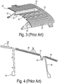
- FIG 4 shows an alternative embodiment of a chute assembly 35 having a main injection-molded body 36 and a stamped sheet-metal hinge plate 37. Opposing sides of plate 37 are insert molded into a chute collar outer flange 38 and a door flap 39 with a center hinge section 40 stamped with an S-shape to provide the desired opening profile. Collar 38 and door flap 39 preferably include welding ribs 34 on their upper surfaces for welding to an instrument panel substrate (not shown), as known in the art.
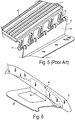
- Figure 5 shows another stamped sheet-metal hinge plate 41 showing a series of S-shaped hinge straps 42 between a door plate insert-molded into a door flap 43 and a base plate 44 which in this embodiment is adapted to extend downward along (and insert molded into) a chute passageway (not shown).
- Hinge straps 42 may be arranged in closely-spaced pairs as shown. The number and individual widths of hinge straps 42 are configured to obtain an appropriate level of flexibility and strength, while the folded and unfolded lengths are configured to provide a desired movement profile when the hidden door is torn open.
- the hinge for a U-shaped, single-panel door is preferably placed at the carforward side of the chute (i.e., the side closest to the windshield). If close enough, then a sweep zone of the door flap might overlap with the windshield so that an impact of the door against the windshield during air bag deployment could occur.
- Figure 6 shows a portion of a vehicle having an instrument panel trim piece 46 at a front passenger side of the vehicle, wherein a hidden door 45 has opened and pivoted toward a windshield 47. Due to the curvature of windshield 47, an outside corner of door 45 may impact windshield 47 at a nearest point 48 where the sweep zone is most likely to overlap the windshield. A smaller diameter chute with a shorter door flap could be used to reduce or eliminate the overlap, but it would be difficult and/or expensive to redesign/modify a customized air bag module with a sufficient inflation gas capacity and deployment profile to meet the performance requirements.
- the present invention utilizes a hinge structure having a plurality of undulating hinge straps with variable lengths.
- one or more hinge straps proximate one lateral end of the hinge e.g., the end having a lower clearance distance from the windshield
- FIG 7 shows a first embodiment of a sheet-metal plate 50 having a hinge section 51 with a plurality of individual hinge straps laterally spaced along one edge of a door flap and arranged in pairs (including hinge straps 52-57).
- Hinge section 51 has a lateral end 58 which is disposed closest to a right or left side of a vehicle (i.e., outboard side) where the air bag placement puts end 58 closest to the windshield (which could alternatively be on the opposite end from the one shown in Figure 7 depending upon the details of the placement and the layout of the vehicle instrument panel and windshield, for example).
- one of more hinge straps proximate one lateral end of the hinge (such as a first hinge strap 52) has a first length which is shorter than a second length of a second hinge strap (such as a hinge strap 57) proximate an opposite lateral end of the hinge.
- a door sweep at lateral end 58 has a smaller radius than at the opposite lateral end. This restricts (i.e., shortens) outward rotation of the door flap at lateral end 58, so that an impact of the corresponding end of the door flap with the windshield can be avoided.
- FIG 8 is a side, cross-sectional view of another embodiment of a stamped sheet metal hinge plate 60 with an undulating hinge strap 61 proximate a near lateral end.
- Another undulating or S-shaped hinge strap 62 proximate the opposite lateral end of the hinge has a greater length so that it's folded position extends farther downward than hinge strap 61.
- hinge strap 61 still has adequate length to allow tearing of the door seam and sufficient rotation of the door flap to allow a deploying air bag to freely exit the opened door.
- an uneven door swing is produced that shortens the sweep zone at the lateral edge of the door flap without adding any tethers or other supplemental parts.
- Figure 9 shows yet another alternative embodiment of a metal door plate with a door flap 71 and mounting wings 72.
- a hinge 73 has individual straps 74-78 with variable strap lengths.
- a lateral end 80 is disposed closest to a windshield. Therefore, a hinge strap 78 has a shortest length and hinge straps 74-76 have a longest length.
- An intermediate strap 77 has an intermediate length.
- the hinge of the invention can alternatively be fabricated entirely of injection molded plastic or other materials, either as an integral part of a single-piece chute assembly or as a separate hinge component affixed to the chute.
Landscapes
- Engineering & Computer Science (AREA)
- Mechanical Engineering (AREA)
- Air Bags (AREA)
- Instrument Panels (AREA)
Abstract
Description
- The present invention relates in general to automotive air bag systems, and, more specifically, to a hidden air bag deployment door formed by an instrument panel substrate and a molded air bag chute.
- Air bag deployment chute assemblies have been put into commercial use for the passenger side of an instrument panel of automotive vehicles. The chute assembly couples an air bag module (typically containing a folded canvas bag and chemical propellants for inflating the bag on command) to a door support panel or substrate of the instrument panel. A typical structure for a chute assembly includes a tubular outer chute wall, one or more door flaps, a flange surrounding the door area, and one or more hinge members or areas connecting the door flap(s) to the outer wall and flange.
- For styling purposes, it is desirable for the air bag deployment door in the instrument panel to be invisible when viewed from the passenger compartment. In other words, the visible or "Class A" surface of the instrument panel is preferably seamless. Therefore, a pre-weakened seam is required in the substrate (on the "Class B" side) to facilitate tearing open of the door during air bag deployment. In order to prevent torn or severed pieces of the substrate from being expelled into the passenger cabin, the door flap(s) of the chute attach to the substrate door area so that the door flap and hinge act as a tether. A common method to attach the chute door flap and flange to the substrate has been by plastic welding, such as vibration welding, hotplate welding, and the like.
- For optimum protection of a passenger, the passenger-side air bag door is placed in or near the top surface of the instrument panel which results in the door being close to the front windshield of the vehicle. Consequently, impingement of the door against the windshield as it swings open during deployment of the air bag becomes a potential pitfall in the event the windshield could be damaged. Vehicle styling trends and a desire for improved aerodynamics often result in the slant (i.e., layback angle) of the windshield being increased and the front-to-back depth of the instrument panel being shortened. In addition, passenger air bags are becoming increasingly large and powerful, which raises the minimum required door size for accommodating deployment of the air bag. Consequently, the potential swing area of the air bag door becomes more likely to intersect with the windshield.
- Due to its momentum from being forced open by the inflating air bag, the air bag door tends to swing beyond the opening size needed to expel the bag. To prevent this, it is known to attach an outer end of the door to the instrument panel via a tether. One or more tethers can be embedded in a chute assembly by overmolding or can be attached as a secondary operation. It would be desirable to avoid the added costs of components and/or assembly associated with tethers while both preventing door contact with the windshield and obtaining a sufficiently large door opening to accommodate a full capacity air bag.
- In one aspect of the invention, an air bag chute assembly for an automotive instrument panel comprises an outer collar configured to attach to the instrument panel. A tubular chute extends interiorly from the collar to a lower end defining a deployment path configured to receive an inflating air bag from an air bag module. A door flap is disposed in an upper end of the chute rotatable from the collar to emerge from the instrument panel. A hinge attaching the door flap to the collar comprises a plurality of S-shaped extendable hinge straps laterally spaced along one edge of the door flap. A first hinge strap proximate one lateral end of the hinge has a first length which is shorter than a second length of a second hinge strap proximate an opposite lateral end of the hinge, thereby restricting rotation of the door flap at the one lateral end.
-
-
Figure 1 is a perspective view of an automotive instrument panel system showing a passenger air bag deployment area. -
Figure 2 is a cross-sectional view along line 2-2 ofFigure 1 showing one type of conventional passenger air bag system. -
Figure 3 is a cross-sectional, perspective view of the air bag chute assembly ofFigure 2 . -
Figure 4 shows a side, cross section of a chute assembly with a conventional overmolded sheet metal door panel. -
Figure 5 is a perspective view of another conventional sheet metal door panel. -
Figure 6 shows a spatial relationship between a windshield and an air bag door. -
Figure 7 is a perspective view of a sheet metal door panel of the invention having a variable hinge extension. -
Figure 8 is a side view of an air bag chute assembly having a sheet metal door panel with a variable hinge extension. -
Figure 9 is a perspective view of another embodiment of a sheet metal door panel with a variable hinge extension. - Referring now to
Figures 1-3 , aninstrument panel 10 includes a passenger air bag system with ahidden seam 11 defining adeployment door area 12. Aninstrument panel substrate 15 provides the desired shape and rigidity for the instrument panel. It is overlaid by acover layer 16 which may include a conventional elastomeric skin and a layer of foam between the skin andsubstrate 15. A chute 17 includes atubular passageway 18 and a deployment door flap 20 at the upper end thereof.Deployment door 20 is coupled topassageway 18 by ahinge 21 along one side. Agap 22 may define an outer edge on three sides ofdoor 20, for example. Instead of a gap, a pre-weakened seam may be employed. Chute 17 includes a flange (collar) 23 surroundingdoor 20. As better shown inFigure 3 ,flange 23 anddoor 20 have a plurality ofribs 24 for welding chute 17 toinstrument panel substrate 15. - As shown in
Figure 2 ,instrument panel substrate 15 and coveringlayer 16 may include ahidden seam 25 for tearing during opening ofdeployment door 20.Seam 25 may be formed by mechanical or laser scoring prior to attachment of chute 17 by vibration welding. Anair bag module 27 is mounted to a plurality ofholes 26 inchute passageway 18.Air bag module 27 is comprised of a rigid box containing apropellant source 30 and a folded bag (not shown) that is guided along a deployment path defined bypassageway 18 todoor 20 upon inflation by gases frompropellant source 30.Air bag module 27 includes a plurality ofhooks 31 that are received in a corresponding plurality ofwindows 26. Afastener 32 couplesair bag module 27 to a cross-car beam via a bracket. - Hinge 21 is preferably formed with an S-shaped or Z-shaped cross section so that
hinge 21 extends lengthwise while simultaneously providing a pivot axis. Therefore,door flap 20 can expand upward more evenly during initial air bag deployment to provide better tearing of the tear seams, and can then pivot out of the way as the air bag emerges from chute 17. - For obtaining a desired strength and appearance, an instrument panel substrate and a chute may be preferably formed of moldable thermoplastic materials. Preferred materials include thermoplastic polyolefin (TPO), Thermal Plastic Elastomers (TPE), and Thermal Plastic Elastomer Olefin (TEO). The most preferred material is TPO compounded with fillers that modify the material's melting temperature, flexural modulus (i.e., stiffness), and other properties.
-
Air bag module 27 is configured to provide an optimal deployment profile for the air bag according to various parameters, such as bag volume, inflation time, gas flow rate, and others. A metal case and an outlet ofair bag module 27 are sized according to these parameters. An internal diameter ofchute passageway 18 is configured to match the outlet ofmodule 27 to provide a smooth transition for the emerging air bag. Similarly,hinge 21 anddoor flap 20 have been configured to deploy in a manner that opens the top end ofpassageway 18 without restriction. -
Figure 4 shows an alternative embodiment of achute assembly 35 having a main injection-moldedbody 36 and a stamped sheet-metal hinge plate 37. Opposing sides ofplate 37 are insert molded into a chute collarouter flange 38 and adoor flap 39 with acenter hinge section 40 stamped with an S-shape to provide the desired opening profile.Collar 38 anddoor flap 39 preferably includewelding ribs 34 on their upper surfaces for welding to an instrument panel substrate (not shown), as known in the art.Figure 5 shows another stamped sheet-metal hinge plate 41 showing a series of S-shaped hinge straps 42 between a door plate insert-molded into adoor flap 43 and abase plate 44 which in this embodiment is adapted to extend downward along (and insert molded into) a chute passageway (not shown).Hinge straps 42 may be arranged in closely-spaced pairs as shown. The number and individual widths of hinge straps 42 are configured to obtain an appropriate level of flexibility and strength, while the folded and unfolded lengths are configured to provide a desired movement profile when the hidden door is torn open. - As previously mentioned, styling and other design considerations for components of a motor vehicle such as the instrument panel front-to-back width and the angling of the windshield can result in a desired position for an air bag deployment door area that is close to the windshield. To keep the door out of the way of the deploying air bag and to minimize the throwing of any loose pieces into a passenger area, the hinge for a U-shaped, single-panel door is preferably placed at the carforward side of the chute (i.e., the side closest to the windshield). If close enough, then a sweep zone of the door flap might overlap with the windshield so that an impact of the door against the windshield during air bag deployment could occur. For example,
Figure 6 shows a portion of a vehicle having an instrumentpanel trim piece 46 at a front passenger side of the vehicle, wherein ahidden door 45 has opened and pivoted toward awindshield 47. Due to the curvature ofwindshield 47, an outside corner ofdoor 45 may impactwindshield 47 at anearest point 48 where the sweep zone is most likely to overlap the windshield. A smaller diameter chute with a shorter door flap could be used to reduce or eliminate the overlap, but it would be difficult and/or expensive to redesign/modify a customized air bag module with a sufficient inflation gas capacity and deployment profile to meet the performance requirements. - To solve the problem of over-rotation of a door flap without adding tethers to restrict the sweep zone of the door, the present invention utilizes a hinge structure having a plurality of undulating hinge straps with variable lengths. In particular, one or more hinge straps proximate one lateral end of the hinge (e.g., the end having a lower clearance distance from the windshield) have a first length which is shorter than a second length of the hinge straps proximate an opposite lateral end of the hinge, thereby restricting rotation of the door flap at the one lateral end.
-
Figure 7 shows a first embodiment of a sheet-metal plate 50 having ahinge section 51 with a plurality of individual hinge straps laterally spaced along one edge of a door flap and arranged in pairs (including hinge straps 52-57).Hinge section 51 has alateral end 58 which is disposed closest to a right or left side of a vehicle (i.e., outboard side) where the air bag placement puts end 58 closest to the windshield (which could alternatively be on the opposite end from the one shown inFigure 7 depending upon the details of the placement and the layout of the vehicle instrument panel and windshield, for example). Atlateral end 58, one of more hinge straps proximate one lateral end of the hinge (such as a first hinge strap 52) has a first length which is shorter than a second length of a second hinge strap (such as a hinge strap 57) proximate an opposite lateral end of the hinge. As a result of the shortened length of hinge strap 52 (as well as straps 53-55 in this illustrated embodiment), a door sweep atlateral end 58 has a smaller radius than at the opposite lateral end. This restricts (i.e., shortens) outward rotation of the door flap atlateral end 58, so that an impact of the corresponding end of the door flap with the windshield can be avoided. -
Figure 8 is a side, cross-sectional view of another embodiment of a stamped sheetmetal hinge plate 60 with an undulatinghinge strap 61 proximate a near lateral end. Another undulating or S-shapedhinge strap 62 proximate the opposite lateral end of the hinge has a greater length so that it's folded position extends farther downward thanhinge strap 61. Although it has a shorter unfolded length (i.e., shallower profile in the folded state), hingestrap 61 still has adequate length to allow tearing of the door seam and sufficient rotation of the door flap to allow a deploying air bag to freely exit the opened door. However, an uneven door swing is produced that shortens the sweep zone at the lateral edge of the door flap without adding any tethers or other supplemental parts. -
Figure 9 shows yet another alternative embodiment of a metal door plate with adoor flap 71 and mountingwings 72. A hinge 73 has individual straps 74-78 with variable strap lengths. A lateral end 80 is disposed closest to a windshield. Therefore, ahinge strap 78 has a shortest length and hinge straps 74-76 have a longest length. Anintermediate strap 77 has an intermediate length. - The hinge of the invention can alternatively be fabricated entirely of injection molded plastic or other materials, either as an integral part of a single-piece chute assembly or as a separate hinge component affixed to the chute.
Claims (11)
- An air bag chute assembly for an automotive instrument panel, comprising:an outer collar configured to attach to the instrument panel;a tubular chute extending interiorly from the collar to a lower end defining a deployment path configured to receive an inflating air bag from an air bag module;a door flap disposed in an upper end of the chute rotatable from the collar to emerge from the instrument panel; anda hinge comprising a plurality of S-shaped extendable hinge straps laterally spaced along one edge of the door flap to attach the door flap to the collar, wherein a first hinge strap proximate one lateral end of the hinge has a first length which is shorter than a second length of a second hinge strap proximate an opposite lateral end of the hinge, thereby restricting rotation of the door flap at the one lateral end.
- The chute assembly of claim 1 wherein a third hinge strap adjacent the first hinge strap has the first length.
- The chute assembly of claim 1 wherein a third hinge strap adjacent the first hinge strap has a third length between the first and second lengths.
- The chute assembly of any of claims 1 to 3 wherein:the hinge is comprised of a center section of a stamped metal sheet;the collar, chute, and door flap are comprised of a molded plastic body wherein the collar and door flap include welding ribs adapted for welding to the instrument panel;a first side section of the metal sheet is insert molded into the door flap; anda second side section of the metal sheet is insert molded into at least one of the collar or chute.
- The chute assembly of any of claims 1 to 4 wherein the plurality of hinge straps are arranged in pairs of more closely spaced straps.
- A passenger air bag system, comprising:an instrument panel substrate defining an opening;the chute assembly of any of claims 1 to 5, wherein the chute assembly is installed at the opening and the door flap emerges from the instrument panel via the opening; andan air bag module mounted to the chute assembly and comprising an inflatable bag for deploying through the chute assembly and opening.
- The passenger air bag system of claim 6 wherein a third hinge strap adjacent the first hinge strap has the first length.
- The passenger air bag system of claim 6 wherein a third hinge strap adjacent the first hinge strap has a third length between the first and second lengths.
- The passenger air bag system of any of claims 6 to 8 wherein:the hinge is comprised of a center section of a stamped metal sheet;the collar, chute, and door flap are comprised of a molded plastic body wherein the collar and door flap include welding ribs adapted for welding to the instrument panel;a first side section of the metal sheet is insert molded into the door flap; anda second side section of the metal sheet is insert molded into at least one of the collar or chute.
- The passenger air bag system of any of claims 6 to 9 wherein the plurality of hinge straps are arranged in pairs of more closely spaced straps.
- An airbag chute, comprising:an elongated chute with a mounting flange surrounding a door flap; anda plurality of undulated hinge straps laterally spaced along one edge of the door flap attaching the door flap to the flange, wherein a first hinge strap proximate one lateral end of the hinge has a first length shorter than a second length of a second hinge strap proximate an opposite lateral end of the hinge.
Applications Claiming Priority (1)
| Application Number | Priority Date | Filing Date | Title |
|---|---|---|---|
| US15/475,290 US9975514B1 (en) | 2017-03-31 | 2017-03-31 | Automotive air bag chute door hinge with variable extension |
Publications (2)
| Publication Number | Publication Date |
|---|---|
| EP3381751A1 true EP3381751A1 (en) | 2018-10-03 |
| EP3381751B1 EP3381751B1 (en) | 2019-05-15 |
Family
ID=60972016
Family Applications (1)
| Application Number | Title | Priority Date | Filing Date |
|---|---|---|---|
| EP18150875.5A Active EP3381751B1 (en) | 2017-03-31 | 2018-01-09 | Automotive air bag chute door hinge with variable extension |
Country Status (5)
| Country | Link |
|---|---|
| US (1) | US9975514B1 (en) |
| EP (1) | EP3381751B1 (en) |
| CN (1) | CN108688603B (en) |
| MX (1) | MX2018003934A (en) |
| RU (1) | RU2671459C1 (en) |
Cited By (1)
| Publication number | Priority date | Publication date | Assignee | Title |
|---|---|---|---|---|
| FR3104511A1 (en) * | 2019-12-12 | 2021-06-18 | Faurecia Interieur Industrie | Vehicle security system |
Families Citing this family (9)
| Publication number | Priority date | Publication date | Assignee | Title |
|---|---|---|---|---|
| US10752197B2 (en) | 2018-04-16 | 2020-08-25 | Ford Global Technologies, Llc | Instrument panel with passenger airbag |
| US10703318B2 (en) * | 2018-04-16 | 2020-07-07 | Ford Global Technologies, Llc | Instrument panel with passenger airbag |
| EP3560772B1 (en) * | 2018-04-26 | 2021-02-24 | Faurecia Interieur Industrie | Airbag system for a vehicle and method for manufacturing the airbag system |
| WO2020006290A1 (en) * | 2018-06-28 | 2020-01-02 | Shanghai Yanfeng Jinqiao Automotive Trim Systems Co. Ltd. | Vehicle trim component |
| US11167716B2 (en) * | 2019-02-05 | 2021-11-09 | Ford Global Technologies, Llc | Reverse-weakened passenger air bag door |
| CN112026705A (en) * | 2019-06-04 | 2020-12-04 | 佛吉亚(中国)投资有限公司 | A cover for covering a safety device in a vehicle |
| CN112550206B (en) * | 2020-12-11 | 2022-09-13 | 上海延锋金桥汽车饰件系统有限公司 | Safety airbag structure |
| US11548465B2 (en) * | 2021-02-17 | 2023-01-10 | Ford Global Technologies, Llc | One way hinge bracket for open frame vehicle side occupant restraint system |
| FR3157307A1 (en) * | 2023-12-22 | 2025-06-27 | Renault S.A.S | Arrangement of a dashboard of a motor vehicle |
Citations (2)
| Publication number | Priority date | Publication date | Assignee | Title |
|---|---|---|---|---|
| JP2009083636A (en) * | 2007-09-28 | 2009-04-23 | Nippon Plast Co Ltd | Airbag device |
| US20140151983A1 (en) * | 2012-06-15 | 2014-06-05 | Thierry Schupbach | Airbag cover door having a variable length hinge |
Family Cites Families (12)
| Publication number | Priority date | Publication date | Assignee | Title |
|---|---|---|---|---|
| KR20020096710A (en) * | 2001-06-21 | 2002-12-31 | 기아자동차주식회사 | Air bag system for automobile |
| US7210700B2 (en) | 2004-08-24 | 2007-05-01 | Visteon Global Technologies, Inc | Hinge mechanism for inflatable restraint apparatus |
| KR100886125B1 (en) * | 2007-11-01 | 2009-02-27 | 현대모비스 주식회사 | Car Instrument Panel |
| KR100890774B1 (en) * | 2007-11-28 | 2009-03-31 | 현대모비스 주식회사 | Car airbag door |
| KR20100127982A (en) | 2009-05-27 | 2010-12-07 | 현대자동차주식회사 | Roof airbag device with limited door rotation |
| EP2284048B1 (en) * | 2009-07-28 | 2014-03-12 | GM Global Technology Operations LLC | Cladding section with airbag flap assembly in the interior of a motor vehicle |
| FR2957872B1 (en) | 2010-03-24 | 2013-07-05 | Faurecia Interieur Ind | INFLATABLE SAFETY CUSHION ARRANGEMENT IN A DASHBOARD COMPRISING A FLAP CONNECTED TO THE DASHBOARD BY A LINEAR LINK. |
| US8181987B2 (en) * | 2010-06-27 | 2012-05-22 | Ford Global Technologies, Llc | Air bag deployment door with force transmitting hinge |
| KR101230829B1 (en) | 2010-10-29 | 2013-02-07 | 현대자동차주식회사 | Structure for door hinge of passenger air bag |
| FR3007349B1 (en) * | 2013-06-24 | 2016-02-26 | Faurecia Interieur Ind | SAFETY DEVICE FOR VEHICLE |
| US9352716B2 (en) * | 2014-03-14 | 2016-05-31 | Ford Global Technologies, Llc | Air bag door hinge for a motor vehicle |
| DE202014003779U1 (en) * | 2014-05-07 | 2015-08-10 | Dalphimetal España S.A. | Module cover, arrangement of a module cover between a vehicle roof and a vehicle roof, gas bag module and vehicle safety system |
-
2017
- 2017-03-31 US US15/475,290 patent/US9975514B1/en active Active
-
2018
- 2018-01-09 EP EP18150875.5A patent/EP3381751B1/en active Active
- 2018-03-16 RU RU2018109365A patent/RU2671459C1/en not_active IP Right Cessation
- 2018-03-27 CN CN201810257014.XA patent/CN108688603B/en active Active
- 2018-03-28 MX MX2018003934A patent/MX2018003934A/en unknown
Patent Citations (2)
| Publication number | Priority date | Publication date | Assignee | Title |
|---|---|---|---|---|
| JP2009083636A (en) * | 2007-09-28 | 2009-04-23 | Nippon Plast Co Ltd | Airbag device |
| US20140151983A1 (en) * | 2012-06-15 | 2014-06-05 | Thierry Schupbach | Airbag cover door having a variable length hinge |
Cited By (1)
| Publication number | Priority date | Publication date | Assignee | Title |
|---|---|---|---|---|
| FR3104511A1 (en) * | 2019-12-12 | 2021-06-18 | Faurecia Interieur Industrie | Vehicle security system |
Also Published As
| Publication number | Publication date |
|---|---|
| CN108688603A (en) | 2018-10-23 |
| EP3381751B1 (en) | 2019-05-15 |
| RU2671459C1 (en) | 2018-10-31 |
| US9975514B1 (en) | 2018-05-22 |
| MX2018003934A (en) | 2018-11-09 |
| CN108688603B (en) | 2022-05-31 |
Similar Documents
| Publication | Publication Date | Title |
|---|---|---|
| EP3381751B1 (en) | Automotive air bag chute door hinge with variable extension | |
| US10220807B2 (en) | Restricted-opening door hinge for automotive air bag chute | |
| US6457738B1 (en) | Inflatable restraint apparatus | |
| US10377336B2 (en) | Molded air bag chute with door reinforced by hollow channel | |
| US9120411B2 (en) | Automotive seat foam pad assembly | |
| US8931798B1 (en) | Foam-in-place interior panels having integrated airbag doors including substrates with airbag chute-door assemblies for motor vehicles | |
| US20140203540A1 (en) | Vehicle Safety Device | |
| US5451075A (en) | Closure for an air bag assembly | |
| US9533649B2 (en) | Seamless passenger airbag system | |
| US5280947A (en) | One piece invisible airbag door and hinge | |
| US6533312B1 (en) | Inflatable restraint apparatus | |
| US11167716B2 (en) | Reverse-weakened passenger air bag door | |
| US6328333B1 (en) | Pillar trim for inflatable restraint system | |
| US7140636B2 (en) | Airbag support assembly for a vehicle instrument panel | |
| US10703318B2 (en) | Instrument panel with passenger airbag | |
| US20060017268A1 (en) | Set for masking safety airbag with reinforcing members and corresponding methods for making same | |
| RU2710507C2 (en) | Active glove box door (embodiments) and internal storage system of vehicle | |
| CN101198491A (en) | Interior panel assembly and airbag device | |
| US10752197B2 (en) | Instrument panel with passenger airbag | |
| US20130082494A1 (en) | Vehicle seat assembly with air bag module having integral protection member | |
| JP4242215B2 (en) | Cover for airbag device and airbag device | |
| JP3892789B2 (en) | Automotive airbag equipment | |
| JP4095873B2 (en) | Automotive airbag equipment | |
| JP4272473B2 (en) | Cover for airbag device and airbag device | |
| JP3663619B2 (en) | Side airbag device for vehicle |
Legal Events
| Date | Code | Title | Description |
|---|---|---|---|
| PUAI | Public reference made under article 153(3) epc to a published international application that has entered the european phase |
Free format text: ORIGINAL CODE: 0009012 |
|
| STAA | Information on the status of an ep patent application or granted ep patent |
Free format text: STATUS: REQUEST FOR EXAMINATION WAS MADE |
|
| 17P | Request for examination filed |
Effective date: 20180620 |
|
| AK | Designated contracting states |
Kind code of ref document: A1 Designated state(s): AL AT BE BG CH CY CZ DE DK EE ES FI FR GB GR HR HU IE IS IT LI LT LU LV MC MK MT NL NO PL PT RO RS SE SI SK SM TR |
|
| AX | Request for extension of the european patent |
Extension state: BA ME |
|
| RIC1 | Information provided on ipc code assigned before grant |
Ipc: B60R 21/215 20110101AFI20181016BHEP |
|
| GRAP | Despatch of communication of intention to grant a patent |
Free format text: ORIGINAL CODE: EPIDOSNIGR1 |
|
| STAA | Information on the status of an ep patent application or granted ep patent |
Free format text: STATUS: GRANT OF PATENT IS INTENDED |
|
| INTG | Intention to grant announced |
Effective date: 20181211 |
|
| GRAS | Grant fee paid |
Free format text: ORIGINAL CODE: EPIDOSNIGR3 |
|
| GRAA | (expected) grant |
Free format text: ORIGINAL CODE: 0009210 |
|
| STAA | Information on the status of an ep patent application or granted ep patent |
Free format text: STATUS: THE PATENT HAS BEEN GRANTED |
|
| AK | Designated contracting states |
Kind code of ref document: B1 Designated state(s): AL AT BE BG CH CY CZ DE DK EE ES FI FR GB GR HR HU IE IS IT LI LT LU LV MC MK MT NL NO PL PT RO RS SE SI SK SM TR |
|
| REG | Reference to a national code |
Ref country code: CH Ref legal event code: EP |
|
| REG | Reference to a national code |
Ref country code: DE Ref legal event code: R082 Ref document number: 602018000061 Country of ref document: DE Representative=s name: HASELTINE LAKE KEMPNER LLP, DE Ref country code: DE Ref legal event code: R082 Ref document number: 602018000061 Country of ref document: DE Representative=s name: HL KEMPNER PATENTANWALT, RECHTSANWALT, SOLICIT, DE |
|
| REG | Reference to a national code |
Ref country code: DE Ref legal event code: R096 Ref document number: 602018000061 Country of ref document: DE |
|
| REG | Reference to a national code |
Ref country code: IE Ref legal event code: FG4D |
|
| REG | Reference to a national code |
Ref country code: NL Ref legal event code: MP Effective date: 20190515 |
|
| REG | Reference to a national code |
Ref country code: LT Ref legal event code: MG4D |
|
| PG25 | Lapsed in a contracting state [announced via postgrant information from national office to epo] |
Ref country code: PT Free format text: LAPSE BECAUSE OF FAILURE TO SUBMIT A TRANSLATION OF THE DESCRIPTION OR TO PAY THE FEE WITHIN THE PRESCRIBED TIME-LIMIT Effective date: 20190915 Ref country code: ES Free format text: LAPSE BECAUSE OF FAILURE TO SUBMIT A TRANSLATION OF THE DESCRIPTION OR TO PAY THE FEE WITHIN THE PRESCRIBED TIME-LIMIT Effective date: 20190515 Ref country code: LT Free format text: LAPSE BECAUSE OF FAILURE TO SUBMIT A TRANSLATION OF THE DESCRIPTION OR TO PAY THE FEE WITHIN THE PRESCRIBED TIME-LIMIT Effective date: 20190515 Ref country code: NL Free format text: LAPSE BECAUSE OF FAILURE TO SUBMIT A TRANSLATION OF THE DESCRIPTION OR TO PAY THE FEE WITHIN THE PRESCRIBED TIME-LIMIT Effective date: 20190515 Ref country code: NO Free format text: LAPSE BECAUSE OF FAILURE TO SUBMIT A TRANSLATION OF THE DESCRIPTION OR TO PAY THE FEE WITHIN THE PRESCRIBED TIME-LIMIT Effective date: 20190815 Ref country code: FI Free format text: LAPSE BECAUSE OF FAILURE TO SUBMIT A TRANSLATION OF THE DESCRIPTION OR TO PAY THE FEE WITHIN THE PRESCRIBED TIME-LIMIT Effective date: 20190515 Ref country code: HR Free format text: LAPSE BECAUSE OF FAILURE TO SUBMIT A TRANSLATION OF THE DESCRIPTION OR TO PAY THE FEE WITHIN THE PRESCRIBED TIME-LIMIT Effective date: 20190515 Ref country code: SE Free format text: LAPSE BECAUSE OF FAILURE TO SUBMIT A TRANSLATION OF THE DESCRIPTION OR TO PAY THE FEE WITHIN THE PRESCRIBED TIME-LIMIT Effective date: 20190515 Ref country code: AL Free format text: LAPSE BECAUSE OF FAILURE TO SUBMIT A TRANSLATION OF THE DESCRIPTION OR TO PAY THE FEE WITHIN THE PRESCRIBED TIME-LIMIT Effective date: 20190515 |
|
| PG25 | Lapsed in a contracting state [announced via postgrant information from national office to epo] |
Ref country code: RS Free format text: LAPSE BECAUSE OF FAILURE TO SUBMIT A TRANSLATION OF THE DESCRIPTION OR TO PAY THE FEE WITHIN THE PRESCRIBED TIME-LIMIT Effective date: 20190515 Ref country code: GR Free format text: LAPSE BECAUSE OF FAILURE TO SUBMIT A TRANSLATION OF THE DESCRIPTION OR TO PAY THE FEE WITHIN THE PRESCRIBED TIME-LIMIT Effective date: 20190816 Ref country code: LV Free format text: LAPSE BECAUSE OF FAILURE TO SUBMIT A TRANSLATION OF THE DESCRIPTION OR TO PAY THE FEE WITHIN THE PRESCRIBED TIME-LIMIT Effective date: 20190515 Ref country code: BG Free format text: LAPSE BECAUSE OF FAILURE TO SUBMIT A TRANSLATION OF THE DESCRIPTION OR TO PAY THE FEE WITHIN THE PRESCRIBED TIME-LIMIT Effective date: 20190815 |
|
| REG | Reference to a national code |
Ref country code: AT Ref legal event code: MK05 Ref document number: 1133048 Country of ref document: AT Kind code of ref document: T Effective date: 20190515 |
|
| PG25 | Lapsed in a contracting state [announced via postgrant information from national office to epo] |
Ref country code: CZ Free format text: LAPSE BECAUSE OF FAILURE TO SUBMIT A TRANSLATION OF THE DESCRIPTION OR TO PAY THE FEE WITHIN THE PRESCRIBED TIME-LIMIT Effective date: 20190515 Ref country code: SK Free format text: LAPSE BECAUSE OF FAILURE TO SUBMIT A TRANSLATION OF THE DESCRIPTION OR TO PAY THE FEE WITHIN THE PRESCRIBED TIME-LIMIT Effective date: 20190515 Ref country code: EE Free format text: LAPSE BECAUSE OF FAILURE TO SUBMIT A TRANSLATION OF THE DESCRIPTION OR TO PAY THE FEE WITHIN THE PRESCRIBED TIME-LIMIT Effective date: 20190515 Ref country code: AT Free format text: LAPSE BECAUSE OF FAILURE TO SUBMIT A TRANSLATION OF THE DESCRIPTION OR TO PAY THE FEE WITHIN THE PRESCRIBED TIME-LIMIT Effective date: 20190515 Ref country code: DK Free format text: LAPSE BECAUSE OF FAILURE TO SUBMIT A TRANSLATION OF THE DESCRIPTION OR TO PAY THE FEE WITHIN THE PRESCRIBED TIME-LIMIT Effective date: 20190515 |
|
| REG | Reference to a national code |
Ref country code: DE Ref legal event code: R097 Ref document number: 602018000061 Country of ref document: DE |
|
| PG25 | Lapsed in a contracting state [announced via postgrant information from national office to epo] |
Ref country code: IT Free format text: LAPSE BECAUSE OF FAILURE TO SUBMIT A TRANSLATION OF THE DESCRIPTION OR TO PAY THE FEE WITHIN THE PRESCRIBED TIME-LIMIT Effective date: 20190515 Ref country code: SM Free format text: LAPSE BECAUSE OF FAILURE TO SUBMIT A TRANSLATION OF THE DESCRIPTION OR TO PAY THE FEE WITHIN THE PRESCRIBED TIME-LIMIT Effective date: 20190515 |
|
| PGFP | Annual fee paid to national office [announced via postgrant information from national office to epo] |
Ref country code: FR Payment date: 20191226 Year of fee payment: 3 |
|
| PLBE | No opposition filed within time limit |
Free format text: ORIGINAL CODE: 0009261 |
|
| STAA | Information on the status of an ep patent application or granted ep patent |
Free format text: STATUS: NO OPPOSITION FILED WITHIN TIME LIMIT |
|
| PG25 | Lapsed in a contracting state [announced via postgrant information from national office to epo] |
Ref country code: TR Free format text: LAPSE BECAUSE OF FAILURE TO SUBMIT A TRANSLATION OF THE DESCRIPTION OR TO PAY THE FEE WITHIN THE PRESCRIBED TIME-LIMIT Effective date: 20190515 |
|
| 26N | No opposition filed |
Effective date: 20200218 |
|
| PG25 | Lapsed in a contracting state [announced via postgrant information from national office to epo] |
Ref country code: PL Free format text: LAPSE BECAUSE OF FAILURE TO SUBMIT A TRANSLATION OF THE DESCRIPTION OR TO PAY THE FEE WITHIN THE PRESCRIBED TIME-LIMIT Effective date: 20190515 |
|
| PG25 | Lapsed in a contracting state [announced via postgrant information from national office to epo] |
Ref country code: MC Free format text: LAPSE BECAUSE OF FAILURE TO SUBMIT A TRANSLATION OF THE DESCRIPTION OR TO PAY THE FEE WITHIN THE PRESCRIBED TIME-LIMIT Effective date: 20190515 |
|
| REG | Reference to a national code |
Ref country code: BE Ref legal event code: MM Effective date: 20200131 |
|
| PG25 | Lapsed in a contracting state [announced via postgrant information from national office to epo] |
Ref country code: LU Free format text: LAPSE BECAUSE OF NON-PAYMENT OF DUE FEES Effective date: 20200109 |
|
| PG25 | Lapsed in a contracting state [announced via postgrant information from national office to epo] |
Ref country code: BE Free format text: LAPSE BECAUSE OF NON-PAYMENT OF DUE FEES Effective date: 20200131 |
|
| REG | Reference to a national code |
Ref country code: DE Ref legal event code: R082 Ref document number: 602018000061 Country of ref document: DE Representative=s name: HL KEMPNER PATENTANWALT, RECHTSANWALT, SOLICIT, DE |
|
| PG25 | Lapsed in a contracting state [announced via postgrant information from national office to epo] |
Ref country code: IE Free format text: LAPSE BECAUSE OF NON-PAYMENT OF DUE FEES Effective date: 20200109 |
|
| REG | Reference to a national code |
Ref country code: CH Ref legal event code: PL |
|
| PG25 | Lapsed in a contracting state [announced via postgrant information from national office to epo] |
Ref country code: FR Free format text: LAPSE BECAUSE OF NON-PAYMENT OF DUE FEES Effective date: 20210131 |
|
| PG25 | Lapsed in a contracting state [announced via postgrant information from national office to epo] |
Ref country code: CH Free format text: LAPSE BECAUSE OF NON-PAYMENT OF DUE FEES Effective date: 20210131 Ref country code: LI Free format text: LAPSE BECAUSE OF NON-PAYMENT OF DUE FEES Effective date: 20210131 |
|
| PGFP | Annual fee paid to national office [announced via postgrant information from national office to epo] |
Ref country code: DE Payment date: 20211216 Year of fee payment: 5 |
|
| PG25 | Lapsed in a contracting state [announced via postgrant information from national office to epo] |
Ref country code: MT Free format text: LAPSE BECAUSE OF FAILURE TO SUBMIT A TRANSLATION OF THE DESCRIPTION OR TO PAY THE FEE WITHIN THE PRESCRIBED TIME-LIMIT Effective date: 20190515 Ref country code: CY Free format text: LAPSE BECAUSE OF FAILURE TO SUBMIT A TRANSLATION OF THE DESCRIPTION OR TO PAY THE FEE WITHIN THE PRESCRIBED TIME-LIMIT Effective date: 20190515 |
|
| PG25 | Lapsed in a contracting state [announced via postgrant information from national office to epo] |
Ref country code: RO Free format text: LAPSE BECAUSE OF FAILURE TO SUBMIT A TRANSLATION OF THE DESCRIPTION OR TO PAY THE FEE WITHIN THE PRESCRIBED TIME-LIMIT Effective date: 20190515 Ref country code: MK Free format text: LAPSE BECAUSE OF FAILURE TO SUBMIT A TRANSLATION OF THE DESCRIPTION OR TO PAY THE FEE WITHIN THE PRESCRIBED TIME-LIMIT Effective date: 20190515 Ref country code: IS Free format text: LAPSE BECAUSE OF FAILURE TO SUBMIT A TRANSLATION OF THE DESCRIPTION OR TO PAY THE FEE WITHIN THE PRESCRIBED TIME-LIMIT Effective date: 20190915 |
|
| GBPC | Gb: european patent ceased through non-payment of renewal fee |
Effective date: 20220109 |
|
| PG25 | Lapsed in a contracting state [announced via postgrant information from national office to epo] |
Ref country code: GB Free format text: LAPSE BECAUSE OF NON-PAYMENT OF DUE FEES Effective date: 20220109 |
|
| REG | Reference to a national code |
Ref country code: DE Ref legal event code: R119 Ref document number: 602018000061 Country of ref document: DE |
|
| PG25 | Lapsed in a contracting state [announced via postgrant information from national office to epo] |
Ref country code: SI Free format text: LAPSE BECAUSE OF FAILURE TO SUBMIT A TRANSLATION OF THE DESCRIPTION OR TO PAY THE FEE WITHIN THE PRESCRIBED TIME-LIMIT Effective date: 20190515 |
|
| PG25 | Lapsed in a contracting state [announced via postgrant information from national office to epo] |
Ref country code: DE Free format text: LAPSE BECAUSE OF NON-PAYMENT OF DUE FEES Effective date: 20230801 |