EP3381744A1 - Vehicle notification device, vehicle notification method and notification signal - Google Patents
Vehicle notification device, vehicle notification method and notification signal Download PDFInfo
- Publication number
- EP3381744A1 EP3381744A1 EP16868304.3A EP16868304A EP3381744A1 EP 3381744 A1 EP3381744 A1 EP 3381744A1 EP 16868304 A EP16868304 A EP 16868304A EP 3381744 A1 EP3381744 A1 EP 3381744A1
- Authority
- EP
- European Patent Office
- Prior art keywords
- frequency
- signals
- sweep
- cycles
- notification
- Prior art date
- Legal status (The legal status is an assumption and is not a legal conclusion. Google has not performed a legal analysis and makes no representation as to the accuracy of the status listed.)
- Granted
Links
Images








Classifications
-
- A—HUMAN NECESSITIES
- A47—FURNITURE; DOMESTIC ARTICLES OR APPLIANCES; COFFEE MILLS; SPICE MILLS; SUCTION CLEANERS IN GENERAL
- A47C—CHAIRS; SOFAS; BEDS
- A47C7/00—Parts, details, or accessories of chairs or stools
- A47C7/62—Accessories for chairs
- A47C7/72—Adaptations for incorporating lamps, radio sets, bars, telephones, ventilation, heating or cooling arrangements or the like
- A47C7/74—Adaptations for incorporating lamps, radio sets, bars, telephones, ventilation, heating or cooling arrangements or the like for ventilation, heating or cooling
-
- B—PERFORMING OPERATIONS; TRANSPORTING
- B60—VEHICLES IN GENERAL
- B60Q—ARRANGEMENT OF SIGNALLING OR LIGHTING DEVICES, THE MOUNTING OR SUPPORTING THEREOF OR CIRCUITS THEREFOR, FOR VEHICLES IN GENERAL
- B60Q9/00—Arrangement or adaptation of signal devices not provided for in one of main groups B60Q1/00 - B60Q7/00, e.g. haptic signalling
-
- B—PERFORMING OPERATIONS; TRANSPORTING
- B60—VEHICLES IN GENERAL
- B60N—SEATS SPECIALLY ADAPTED FOR VEHICLES; VEHICLE PASSENGER ACCOMMODATION NOT OTHERWISE PROVIDED FOR
- B60N2/00—Seats specially adapted for vehicles; Arrangement or mounting of seats in vehicles
- B60N2/90—Details or parts not otherwise provided for
-
- B—PERFORMING OPERATIONS; TRANSPORTING
- B60—VEHICLES IN GENERAL
- B60R—VEHICLES, VEHICLE FITTINGS, OR VEHICLE PARTS, NOT OTHERWISE PROVIDED FOR
- B60R11/00—Arrangements for holding or mounting articles, not otherwise provided for
- B60R11/02—Arrangements for holding or mounting articles, not otherwise provided for for radio sets, television sets, telephones, or the like; Arrangement of controls thereof
-
- B—PERFORMING OPERATIONS; TRANSPORTING
- B60—VEHICLES IN GENERAL
- B60R—VEHICLES, VEHICLE FITTINGS, OR VEHICLE PARTS, NOT OTHERWISE PROVIDED FOR
- B60R21/00—Arrangements or fittings on vehicles for protecting or preventing injuries to occupants or pedestrians in case of accidents or other traffic risks
-
- G—PHYSICS
- G08—SIGNALLING
- G08B—SIGNALLING SYSTEMS, e.g. PERSONAL CALLING SYSTEMS; ORDER TELEGRAPHS; ALARM SYSTEMS
- G08B21/00—Alarms responsive to a single specified undesired or abnormal condition and not otherwise provided for
-
- G—PHYSICS
- G08—SIGNALLING
- G08G—TRAFFIC CONTROL SYSTEMS
- G08G1/00—Traffic control systems for road vehicles
- G08G1/16—Anti-collision systems
-
- H—ELECTRICITY
- H04—ELECTRIC COMMUNICATION TECHNIQUE
- H04R—LOUDSPEAKERS, MICROPHONES, GRAMOPHONE PICK-UPS OR LIKE ACOUSTIC ELECTROMECHANICAL TRANSDUCERS; ELECTRIC HEARING AIDS; PUBLIC ADDRESS SYSTEMS
- H04R1/00—Details of transducers, loudspeakers or microphones
-
- H—ELECTRICITY
- H04—ELECTRIC COMMUNICATION TECHNIQUE
- H04R—LOUDSPEAKERS, MICROPHONES, GRAMOPHONE PICK-UPS OR LIKE ACOUSTIC ELECTROMECHANICAL TRANSDUCERS; ELECTRIC HEARING AIDS; PUBLIC ADDRESS SYSTEMS
- H04R3/00—Circuits for transducers
-
- B—PERFORMING OPERATIONS; TRANSPORTING
- B60—VEHICLES IN GENERAL
- B60N—SEATS SPECIALLY ADAPTED FOR VEHICLES; VEHICLE PASSENGER ACCOMMODATION NOT OTHERWISE PROVIDED FOR
- B60N2/00—Seats specially adapted for vehicles; Arrangement or mounting of seats in vehicles
- B60N2/90—Details or parts not otherwise provided for
- B60N2002/981—Warning systems, e.g. the seat or seat parts vibrates to warn the passenger when facing a danger
Definitions
- the present invention relates to a vehicle notification device, vehicle notification method, and notification signals and, more specifically, to a vehicle notification device, vehicle notification method, and notification signals that are able to notify the user through vibrations.
- Such an audio system includes a full-range speaker installed near the headrest of the seat and subwoofers installed in the backrest or seat surface of the seat and is able to output sounds in a low-to-high wide frequency range.
- the subwoofers are embedded in the seat and configured to vibrate the seat in accordance with the level of a low-frequency-band music signal.
- Subwoofers are not used solely to enhance the realism of music by outputting deep bass (low-frequency sounds). They have been also used recently as means for notifying the driver (alarm means).
- vehicle notification devices that when the vehicle crosses a lane marking, notify the driver that the vehicle has crossed the lane marking through vibrations, as well as notify the driver of the position of the crossed lane marking using the vibration position of the seat (for example, see Patent Literature 3).
- vehicle notification device determines whether the driver is dozing by detecting the heart rate of the driver using a heart rate monitor and awakens the driver by vibrating a vibrator (exciter) disposed in a seat (see Patent Literature 4).
- an alarm or notification can be issued to the driver by vibrating a vibrator (subwoofer, etc.) disposed in the driver's seat when necessary.
- a vibrator subwoofer, etc.
- Typical examples of speakers embedded in the seat include dynamic speakers using cone paper or the like and exciters that output a sound or vibration by vibrating the contact surface.
- Examples of a sound source that vibrates a speaker include sinusoidal signals and sweep signals.
- the term "sweep signal” refers to a signal obtained by gradually changing the frequency of an output sound.
- a notification device including speakers embedded in the seat needs to output high-level sound signals so that the user can reliably feel vibrations.
- a steady-state traveling vibration is transmitted to the seat depending on the road conditions and thus the seat may cause a low-frequency vibration.
- the frequency band of such a low-frequency seat vibration may be the same as that of a low-frequency alarm vibration from the speaker or exciter, disadvantageously making it difficult for the driver to distinguish between the vehicle vibration and the alarm vibration.
- the alarm vibration is masked by the vehicle vibration and the driver has difficulty in distinguishing the alarm vibration from the vehicle vibration, it is considered to use a method of making the frequency band of the alarm signal different from the frequency band of the vehicle vibration by intentionally increasing the frequency of the alarm signal.
- the frequency band of the alarm signal is increased, the propagation mode (vibration transmission characteristics) of the seat changes with respect to the low-band alarm signal. The change in the propagation mode tends to reduce the vibration component of the alarm signal and thus the alarm signal tends to be outputted as a sound component.
- the alarm vibration outputted as a sound propagates through the space. As a result, the alarm sound is transmitted to a passenger other than the driver, unfavorably making the passenger anxious.
- the present invention has been made in view of the above problem, and an object thereof is to provide a vehicle notification device, vehicle notification method, and notification signals that when an alarm vibration is outputted from a speaker, exciter, or the like disposed in a seat, allow the driver to reliably distinguish the alarm signal even in a situation in which the alarm vibration may be masked depending on the road conditions.
- Another object of the present invention is to provide a vehicle notification device, vehicle notification method, and notification signals that when an alarm vibration is outputted from a vibration device such as a speaker or exciter disposed in a seat, are able to prevent burn-out of the vibration device.
- a vibration device such as a speaker or exciter disposed in a seat
- a vehicle notification device includes a plurality of vibrators independently disposed in a seat, a storage unit configured to store a plurality of pieces of signal data that are different in a combination of an initial frequency and a target frequency, and a signal generator configured to randomly extract one of the pieces of signal data stored in the storage unit by the number of the vibrators and to generate a plurality of sweep signals corresponding to the number of the vibrators, each of the sweep signals being generated by changing a frequency from the initial frequency to the target frequency of the extracted piece of signal data in cycles.
- a plurality of notification vibrations whose frequencies change in different frequency ranges are outputted from a plurality of positions of the seat by outputting the sweep signals generated by the signal generator, individually from the vibrators.
- a vehicle notification method performed by a vehicle notification device that outputs notification vibrations from a plurality of vibrators independently disposed in a seat.
- the method includes a sweep signal generation step of randomly extracting, by a signal generator, one of a plurality of pieces of signal data stored in a storage unit by the number of the vibrators, the pieces of signal data being different in a combination of an initial frequency and a target frequency, and generating a plurality of sweep signals corresponding to the number of the vibrators, each of the sweep signals being generated by changing a frequency from the initial frequency to the target frequency of the extracted piece of signal data in cycles, and a vibration output step of outputting a plurality of notification vibrations whose frequencies change in different frequency ranges, from a plurality of positions of the seat by outputting the sweep signals generated in the sweep signal generation step, individually from the vibrators.
- Notification signals of a vehicle notification device inputted to a plurality of vibrators independently disposed in a seat so that notification vibrations are outputted from the vibrators.
- the notification signals are sweep signals whose frequency components are swept by randomly extracting one of a plurality of pieces of signal data, the pieces of signal data being different in a combination of an initial frequency and a target frequency, and changing frequencies from the initial frequency to the target frequency of the extracted piece of signal data in cycles.
- the vehicle notification device, vehicle notification method, and notification signals described above are able to generate sweep signals having different frequency ranges on the basis of a randomly extracted combination of an initial frequency and a target frequency of multiple combinations of initial frequencies and target frequencies and to output the different sweep signals from the multiple vibrators. Since the wavelengths of the sweep signals are changed in each cycle by changing the initial frequency and target frequency of the sweep signals, notification vibrations having various frequency components can be outputted from the respective positions of the seat.
- the multiple vibrators are disposed in the seat, notification vibrations having different frequency components can be outputted individually from the vibrators.
- the recognizability and distinguishability of notification vibrations by the driver can be improved.
- the attention of the driver to notification vibrations can be increased significantly. Even in a situation in which alarm vibrations may be masked by a steady-state vibration transmitted from the road surface to the seat depending on the road conditions while the vehicle travels, it is possible to improve the recognizability and distinguishability of notification vibrations by the driver and to significantly increase the attention of the driver to notification vibrations.
- the vehicle notification device described above further includes a delay signal generator configured to, by continuously randomly extracting one time value from a time range of each of the cycles as a delay time value, generate a plurality of delay signals indicating change states of the delay time values, and a variable delay unit configured to delay the sweep signals generated by the signal generator in each of the cycles on the basis of the change states of the delay time values in the delay signals.
- a delay signal generator configured to, by continuously randomly extracting one time value from a time range of each of the cycles as a delay time value, generate a plurality of delay signals indicating change states of the delay time values
- a variable delay unit configured to delay the sweep signals generated by the signal generator in each of the cycles on the basis of the change states of the delay time values in the delay signals.
- the vehicle notification method described above further includes a delay signal generation step of, by continuously randomly extracting one time value from a time range of each of the cycles as a delay time value, generating, by a delay signal generator, a plurality of delay signals indicating change states of the delay time values, and a variable delay step of delaying, by a variable delay unit, the sweep signals generated in the sweep signal generation step in each of the cycles on the basis of the change states of the delay time values in the delay signals generated in the delay signal generation step.
- the vehicle notification device, vehicle notification method, and notification signals are able to delay multiple sweep signals in each cycle on the basis of the change states of the delay time values in the multiple delay signals.
- the timings when notification vibrations are outputted from the multiple vibrators can be changed.
- the timings when notification vibrations are outputted from the multiple vibrators can be changed.
- alarm vibrations may be masked by a steady-state vibration transmitted from the road surface to the seat depending on the road conditions while the vehicle travels, it is possible to improve the recognizability and distinguishability of notification vibrations by the driver and to significantly increase the attention of the driver to notification vibrations.
- vehicle notification device described above further includes at least one of an amplitude changer configured to randomly change amplitude values of the sweep signals generated by the signal generator in each of the cycles, and an occurrence frequency controller configured to suppress occurrence of the notification vibrations in each of the cycles by randomly limiting the amplitude values of the sweep signals generated by the signal generator to zero in each of the cycles.
- vehicle notification method described above further includes at least one of an amplitude change step of randomly changing, by an amplitude changer, amplitude values of the sweep signals generated in the sweep signal generation step in each of the cycles, and an occurrence frequency control step of suppressing, by an occurrence frequency controller, occurrence of the notification vibrations in each of the cycles by randomly limiting the amplitude values of the sweep signals generated in the sweep signal generation step to zero in each of the cycles.
- the processes include a process of randomly changing amplitude values of the sweep signals in each of the cycles and a process of suppressing occurrence of the notification vibrations in each of the cycles by randomly limiting the amplitude values of the sweep signals to zero in each of the cycles.
- the vehicle notification device, vehicle notification method, and notification signals randomly change the amplitude values of the cycles of the sweep signals, or randomly limit the amplitude values of the cycles of the sweep signals to zero and thus are able to suppress occurrence of a notification vibration in one cycle. That is, the vehicle notification device, vehicle notification method, and notification signals are able to change notification vibrations outputted from the vibrators to different amplitude values corresponding to the vibrators or to randomly suppress occurrence of a notification vibration in one cycle.
- the signal generator when changing frequencies of the sweep signals from the initial frequency to the target frequency, changes amplitude values in accordance with changes in the frequencies.
- the sweep signal generation step includes when changing frequencies of the sweep signals from the initial frequency to the target frequency, changing, by the signal generator, amplitude values in accordance with changes in the frequencies.
- the vehicle notification device, vehicle notification method, and notification signals are able to change the amplitude values in accordance with changes in the frequencies.
- the vehicle notification device and the like are able to gradually increase the amplitude values of the sweep signals from the initial frequency, to maximize the amplitude values at one of frequencies from the initial frequency to the target frequency, and to gradually reduce the amplitude values of the sweep signals from the one frequency toward the target frequency.
- the amplitude values in one cycle of the sweep signals can be changed by changing the amplitudes in accordance with changes in the frequencies.
- the vehicle notification device, vehicle notification method, and notification signals of an embodiment of the present invention are able to generate sweep signals having different frequency ranges on the basis of a randomly extracted combination of an initial frequency and a target frequency of multiple combinations of initial frequencies and target frequencies and to output the different sweep signals from the multiple vibrators. Since the wavelengths of the sweep signals are changed in each cycle by changing the initial frequency and target frequency of the sweep signals, notification vibrations having various frequency components can be outputted from the respective positions of the seat.
- the multiple vibrators are disposed in the seat, notification vibrations having different frequency components can be outputted individually from the vibrators.
- the recognizability and distinguishability of notification vibrations by the driver can be improved.
- the attention of the driver to notification vibrations can be increased significantly. Even in a situation in which alarm vibrations may be masked by a steady-state vibration transmitted from the road surface to the seat depending on the road conditions while the vehicle travels, it is possible to improve the recognizability and distinguishability of notification vibrations by the driver and to significantly increase the attention of the driver to notification vibrations.
- FIG. 1 is a block diagram showing a schematic configuration of a vehicle alarm device according to an embodiment.
- a vehicle alarm device (vehicle notification device) 1 includes a sweep signal generator 2, a generation frequency controller (occurrence frequency controller) 3, a generation level controller (amplitude changer) 4, a generation delay controller 5, an amplifier 6, and four exciters (vibrators) EX1, EX2, EX3, and EX4.
- an alarm information output unit 10 Connected to the sweep signal generator 2 is an alarm information output unit 10 that generates alarm information serving as a determination criterion on whether to cause the exciters EX1 to EX4 to generate alarm vibrations.
- the alarm information output unit 10 generates alarm information based on such as a lane departure signal, vehicle approach information, doze detection information, and a sharp curve signal and outputs the generated information to the sweep signal generator 2.
- the alarm information output unit 10 detects these alarming matters using a typical method such as a method of capturing images of the front of the vehicle and analyzing the images or a method of detecting an alarming matter by radiating a radar wave forward and measuring a reflected wave.
- the exciters EX1 to EX4 serve as vibration devices that caution the driver by individually outputting vibrations and sounds for notification.
- the vibration devices need not be exciters and may be another type of devices such as dynamic speakers.
- the term "exciter” refers to an output device that is able to transmit a vibration force from the voice coil thereof to an object in contact with the exciter and to cause the object to output a vibration or sound as a diaphragm.
- FIG. 2 is a drawing schematically showing a state in which the exciters EX1 to EX4 are installed in a driver's seat (seat) 20 of a vehicle.
- the exciter EX1 is installed in a front-left portion of a seat surface 21 of the driver's seat 20;
- the exciter EX2 is installed in a front-right portion of the seat surface 21;
- the exciter EX3 is installed in an upperleft portion of a backrest 22 of the driver's seat 20;
- the exciter EX4 is installed in an upperright portion of the backrest 22.
- the exciters EX1 to EX4 are installed in a cushion that is the interior member of the seat surface 21 and backrest 22.
- the exciters EX1 to EX4 need not be installed in positions shown in FIG. 2 and may be installed in any positions as long as the positions are positions in which the driver can distinguish the vibrations of the exciters EX1 to EX4 through his or her body portions while driving the vehicle. For this reason, the installation positions of the exciters EX1 to EX4 can be changed flexibly.
- the exciters EX3 and EX4 need not be installed in the upper left and right positions of the backrest 22 and may be installed, for example, in lower left and right positions of the backrest 22.
- the exciter EX3 and exciter EX4 may be installed in rear left and right positions of the seat surface 21.
- the number of exciters need not be four and may be more than four or less than four.
- the sweep signal generator 2 has a function of, when receiving alarm information from the alarm information output unit 10, generating alarm sweep signals on the basis of the alarm information.
- FIG. 3 is a block diagram showing a schematic configuration of the sweep signal generator 2. As shown in FIG. 3 , the sweep signal generator 2 includes four signal generators 2a (2a-1, 2a-2, 2a-3, and 2a-4), a weighting unit 2b, and a storage unit 2c. The four signal generators 2a are disposed so as to correspond to the four exciters, EX1 to EX4. The signal generators 2a (2a-1 to 2a-4) generate sweep signals on the basis of alarm information received from the alarm information output unit 10.
- the sweep signal generator 2 While receiving alarm information from the alarm information output unit 10, the sweep signal generator 2 continuously generates sweep signals using the signal generators 2a and weighting unit 2b and continuously outputs the sweep signals to the generation frequency controller 3. Note that the sweep signal generator 2 generates sweep signals to be inputted to the exciters EX1 to EX4 (four sweep signals) and outputs the sweep signals to the generation frequency controller 3.
- Each signal generator 2a generates a sweep signal consisting of a sine wave. Specifically, each signal generator 2a generates a sweep signal by sweeping the frequency of the sine wave in a low frequency band. If the exciters are vibrated using sweep signals corresponding to the entire frequency band, the vibration characteristics (vibration propagation mode) of the driver's seat 20 may change, so the vibration component may be changed into a sound component. In this case, the alarm vibration may be changed into a sound, which then may propagate through the space and may be recognized as an alarm sound by a passenger other than the driver. For this reason, a sweep signal is generated by sweeping only a low frequency band of the sine wave. Thus, recognition of the alarm vibration as a sound by the passenger can be prevented.
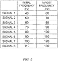
- FIG. 5 is a table showing the combinations of initial frequencies and target frequencies of the eight signals, 1 to 8, stored in the storage unit 2c. Note that the storage unit 2c may be disposed independently of the sweep signal generator 2.
- the signal generators 2a are able to access the storage unit 2c and to read (extract) information about one of the signals 1 to 8 (signal data) shown in the table of FIG. 5 from the storage unit 2c.
- the signal generators 2a then determine the initial frequency and target frequency on the basis of the signal information read from the storage unit 2c.
- the signal generators 2a then generate sweep signals by smoothly changing the frequency of the sine wave in the frequency range from the determined initial frequency to target frequency.
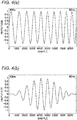
- FIG. 4(a) is a diagram showing an example of amplitude characteristics of one cycle of a sweep signal generated by the signal generator 2a. More specifically, FIG. 4(a) shows one cycle of a sweep signal obtained by changing the frequency of the sine wave from an initial frequency of 40 Hz to a target frequency of 60 Hz (that is, one cycle of a sweep signal whose frequency band to be swept ranges from 40 Hz to 60 Hz).
- One cycle of the sweep signal shown in FIG. 4(a) is 0.2 sec, and the sampling frequency thereof is 44.1 kHz. In this cycle, the frequency of the sweep signal is changed from 40 Hz to 60 Hz. Also, as shown in FIG. 4(a) , the cycle of 0.2 sec of the sweep signal corresponds to 8,821 samples.
- the weighting unit 2b weights the sweep signals generated by the signal generators 2a.
- the weighting unit 2b according to the embodiment weights the sweep signals using a Hann window, which is an example window function.
- FIG. 4(b) shows amplitude characteristics of a sweep signal cycle obtained by weighting the cycle of the sweep signal shown in FIG. 4(a) using a Hann window.
- the weighting unit 2b need not perform weighting using a window function and may perform weighting using any method as long as the method allows for sufficient attenuation of the amplitude around the initial frequency of the sweep signal and the amplitude around the target frequency thereof. Also, a Hann window need not be used when performing weighting using a window function and another window function may be used.
- the weighted sweep signal cycle has amplitude characteristics where the amplitude value changes in accordance with changes in the frequency.
- the sweep signal cycle is controlled/deformed into a pulse-shaped signal due to the weighting of the amplitude value.
- the amplitude value of each cycle of a sweep signal can be changed by weighting.
- continuous input of signals having a uniform level (signal level, amplitude value) to the vibration devices such as the exciters EX1 to EX4 can be prevented while maintaining the feeling of vibration of the seat.
- continuous input of signals having a uniform level can be prevented from causing an overcurrent in the vibration devices and thus causing burn-out of the vibration devices.
- the vibration devices can reduce the power consumption thereof compared to when outputting signals having a uniform level.
- the vibrations can cause resonance.
- the signal frequency at which the resonance occurs is called "resonant frequency.”
- the resonant frequency depends on the specific frequency of the member in which the exciters EX1 to EX4 are disposed. Even if low-level signals are outputted from the exciters EX1 to EX4, relatively large vibrations can be generated by resonance. For this reason, when giving an alarm to the driver through vibrations, signals having a resonant frequency are outputted from the exciters EX1 to EX4. Thus, the output of the amplifier 6 can be reduced, resulting in power savings.
- the resonant frequency is characterized to change due to the individual differences between the vibration devices such as the exciters EX1 to EX4, variations in the properties of the material of the driver's seat 20, which transmits vibrations, the difference between the installation positions of the exciters EX1 to EX4, the aged deterioration of the exciters EX1 to EX4, the seat material, mounting members, or the like, or others.
- the signal generators 2a use, as alarm signals (sweep signals), sine waves obtained by sweeping the frequency rather than using sinusoidal signals based on a single frequency.
- alarm signals can cause resonance.
- the signal generators 2a can change the frequency range to be swept when generating sweep signals, by randomly changing the initial frequency and target frequency.
- the four signal generators 2a-1 to 2a-4 independently randomly extract one of the signals 1 to 8 shown in FIG. 5 from the storage unit 2c and generate sweep signals on the basis of the initial frequencies and target frequencies of the extracted signals.
- the signals 1 to 8 are different in a combination of an initial frequency and a target frequency.
- the signal generators 2a-1 to 2a-4 can generate sweep signals having different frequency ranges in which the frequency changes (frequency ranges to be swept).
- FIG. 6 shows output characteristics (amplitude characteristics) of sweep signals generated by the signal generators 2a-1 to 2a-4 by randomly extracting one of the signals 1 to 8 shown in the table of FIG. 5 and thus changing the combination of the initial frequency and target frequency.
- the signal generators 2a generate sweep signals corresponding to the exciters EX1 to EX4.
- FIG. 6 shows four sweep signals to be outputted from EX1 to EX4.
- each pulse-shaped signal of the sweep signals are changed by changing the initial frequency and target frequency.
- alarm vibrations having various frequency components can be outputted from the exciters disposed in the respective seat positions of the driver's seat 20.
- alarm vibrations having different frequency components are outputted from the exciters EX1 to EX4 disposed in four positions of the driver's seat 20.
- each signal generator 2a generates a sweep signal as a signal having cycles of 0.2 sec (a signal corresponding to 8,821 samples).
- the cycle length of a sweep signal is not limited to this length.
- the four signal generators 2a (2a-1 to 2a-4) according to the embodiment can independently randomly change the cycle length of a sweep signal.
- the four sweep signals generated by the sweep signal generator 2 are outputted as a first sweep signal A, a first sweep signal B, a first sweep signal C, and a first sweep signal D to the generation frequency controller 3.
- the generation frequency controller 3 has a function of controlling the frequency with which alarm vibrations to be outputted from the exciters EX1 to EX4 are generated.
- the sweep signal generator 2 generates the cycles of sweep signals into pulse-shaped signals on the basis of alarm information from the alarm information output unit 10 and continuously outputs the sweep signals to the generation frequency controller 3. Accordingly, if the generation frequency controller 3 does not control the frequency with which alarm vibrations are generated, pulse-shaped signals are continuously outputted from the exciters EX1 to EX4 and thus alarm vibrations are continuously generated.
- the generation frequency controller 3 controls the frequency with which alarm vibrations are generated, alarm vibrations are sometimes generated and sometimes not generated by the exciters EX1 to EX4. That is, the alarm vibration output pattern (occurrence pattern) can be changed by controlling the generation frequency. This can prevent the fixing of the alarm vibration output pattern, thereby preventing the driver from becoming insensitive to alarm vibrations.
- FIG. 7 is a block diagram showing a schematic configuration of the generation frequency controller 3.
- the generation frequency controller 3 includes four first uniform distribution generators 3a (3a-1, 3a-2, 3a-3, and 3a-4) and four variable frequency units 3b (3b-1, 3b-2, 3b-3, and 3b-4).
- the four first uniform distribution generators 3a and four variable frequency units 3b are disposed so as to be associated with the exciters EX1 to EX4.
- the four variable frequency units 3b receive the first sweep signals A to D.
- Each first uniform distribution generator 3a randomly extracts one value from a preset value range. If the extracted value is equal to or smaller than a preset threshold, the first uniform distribution generator 3a outputs a control signal to permit the output of an alarm vibration, to the corresponding variable frequency unit 3b. If the extracted value is greater than the predetermined threshold, the first uniform distribution generator 3a outputs a control signal to prohibit the output of an alarm vibration, to the variable frequency unit 3b.
- FIG. 8(a) is a diagram showing an example of output characteristics of the first uniform distribution generator 3a.
- the preset value range is 0.00 to 4.00, and the threshold is set to 3.00.
- the "frequency” represented by the vertical axis of FIG. 8(a) means the ratio at which each value of 0.00 to 4.00 is extracted by the first uniform distribution generator 3a.
- FIG. 8(a) shows that any value is randomly extracted from the value range 0.00 to 4.00 at a uniform ratio.
- the output characteristics of the first uniform distribution generator 3a shown in FIG. 8(a) indicates that a "signal to permit output" is outputted as a control signal to the corresponding variable frequency unit 3b at a ratio of 3/4.
- the output characteristics also indicates that a "signal to prohibit output” is outputted as a control signal to the variable frequency unit 3b at a ratio of 1/4.
- variable frequency unit 3b outputs only one cycle (only one pulse-shaped signal) of the first sweep signal received from the sweep signal generator 2 to the generation level controller 4.
- variable frequency unit 3b limits the amplitude of one cycle (one pulse-shaped signal) of the first sweep signal received from the sweep signal generator 2 to 0 (zero) and outputs the resulting first sweep signal to the generation level controller 4, or the variable frequency unit 3b blocks only one cycle (only one pulse-shaped signal) of the first sweep signal received from the sweep signal generator 2 so that the first sweep signal is not outputted to the generation level controller 4.
- FIG. 9 is a diagram showing output characteristics of signals obtained by controlling the generation frequencies of the pulse-shaped signals in the first sweep signals A to D whose initial frequencies are set to 40 Hz and whose target frequencies are set to 60 Hz, on the basis of output characteristics of the first uniform distribution generator 3a shown in FIG. 8(a) .
- FIG. 9 shows that the pulse-shaped signals (0.2 sec-cycle weighted signals) in the sweep signals are outputted at random frequencies.
- the four sweep signals shown in FIG. 9 are defined as a second sweep signal A, a second sweep signal B, a second sweep signal C, and a second sweep signal D.
- the pulse-shaped signals (cycles) of the second sweep signals are outputted at the above ratio of 3/4. Accordingly, three cycles are averagely outputted with respect to pulse-shaped signals forming four cycles.
- the generation frequencies of the pulse-shaped signals in the second sweep signals can be changed by changing the threshold value shown in FIG. 8(a) .
- the generation frequency of pulse-shaped signals can be reduced by setting the threshold value to a smaller value.
- the second sweep signals A to D are generated so as to correspond to the exciters EX1 to EX4.
- the four first uniform distribution generators 3a and four variable frequency units 3b perform the generation frequency control process on the sweep signals to be inputted to the exciters EX1 to EX4.
- the generation frequencies and generation states of the pulse-shaped signals in the second sweep signals A to D shown in FIG. 9 are determined independently of each other without being influenced by each other.
- the four second sweep signals A to D subjected to the pulse-shaped signal generation frequency control process by the generation frequency controller 3 are outputted to the generation level controller 4.
- the generation level controller 4 has a function of controlling the levels of the sweep signals (second sweep signals A to D) subjected to the pulse-shaped signal generation frequency control process in each cycle by the generation frequency controller 3.
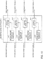
- FIG. 10 is a block diagram showing a schematic configuration of the generation level controller 4.
- the generation level controller 4 includes four second uniform distribution generators 4a (4a-1, 4a-2, 4a-3, and 4a-4) and four variable level units 4b (4b-1, 4b-2, 4b-3, and 4b-4).
- the four first uniform distribution generators 4a and four variable level units 4b are disposed so as to be associated with the exciters EX1 to EX4.
- the four variable level units 4b receive the second sweep signals A to D.
- Each second uniform distribution generator 4a randomly extracts one level value from a preset value range and outputs information about the extracted level value (level value information) to the corresponding variable level unit 4b.
- FIG. 8(b) is a diagram showing an example of output characteristics of the second uniform distribution generator 4a.
- the preset value range is -12 dB to 0 dB.
- the "frequency" represented by the vertical axis of FIG. 8(b) means the ratio at which each value of -12 dB to 0 dB is extracted by the second uniform distribution generator 4a.
- FIG. 8(b) shows that a level value is randomly extracted from the value range of -12 dB to 0 dB at a uniform ratio.
- variable level units 4b control the signal levels of the cycles (pulse-shaped signals) of the second sweep signals A to D received from the generation frequency controller 3 on the basis of the level value information received from the second uniform distribution generators 4a and output the resulting signals to the generation delay controller 5. Specifically, the variable level units 4b determine the level values on the basis of the level value information acquired from the second uniform distribution generators 4a and convert the level values in decibel (dB) to those in linear (amplitude value). After linear-converting the level values, the variable level units 4b weight (control) the amplitude values of the cycles (pulse-shaped signals) of the second sweep signals A to D. The variable level units 4b-1 to 4b-4 independently weight the respective second sweep signals.
- FIG. 11 is a diagram showing an example of output characteristics of four sweep signals obtained by the generation level controller 4 by weighting the amplitude values (signal levels) of the second sweep signals A to D subjected to the generation frequency control process by the generation frequency controller 3.
- the four sweep signals shown in FIG. 11 are defined as a third sweep signal A, a third sweep signal B, a third sweep signal C, and a third sweep signal D.
- FIG. 11 shows that the amplitude values of the pulse-shaped signals (cycles) in the third sweep signals A to D have been randomly controlled/changed. Specifically, FIG. 11 shows that cycles (pulse-shaped signals) having smaller amplitude values have been weighted using smaller level values.
- FIG. 11 shows a case in which the level value range for weighting is -12 dB to 0 dB
- the level value range is not limited to -12 dB to 0 dB.
- the amplitude values (signal levels) of the weighted sweep signals (third sweep signals A to D) can be changed more greatly.
- the third sweep signals A to D are generated so as to correspond to the exciters EX1 to EX4. For this reason, the four second uniform distribution generators 4a and four variable level units 4b weight the sweep signals to be inputted to the exciters EX1 to EX4.
- the amplitude values of the sweep signals (third sweep signals A to D) shown in FIG. 11 have been weighted independently of each other without being influenced by each other.
- the four third sweep signals A to D subjected to the amplitude value (signal level) weighting process by the generation level controller 4 are outputted to the generation delay controller 5.
- the generation delay controller 5 has a function of controlling the playback time positions of the sweep signals (third sweep signals) weighted by the generation level controller 4. Specifically, the generation delay controller 5 randomly changes the playback time positions of the third sweep signals A to D. To randomly change the playback time positions, the generation delay controller 5 continuously changes the timings when alarm vibrations are outputted from the exciters EX1 to EX4, on the basis of the four third sweep signals A to D.
- FIG. 12 is a diagram showing an example of output characteristics of signals whose playback time positions have been randomly changed by the generation delay controller 5.
- the sweep signals whose playback time positions have been controlled by the generation delay controller 5 are defined as a fourth sweep signal A, a fourth sweep signal B, a fourth sweep signal C, and a fourth sweep signal D.
- FIG. 12 shows a state in which the playback time positions of the pulse-shaped signals (cycles) in the sweep signals are being changed independently of each other.
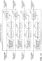
- FIG. 13 is a block diagram showing a schematic configuration of the generation delay controller 5.
- the generation delay controller 5 includes four third uniform distribution generators 5a (5a-1, 5a-2, 5a-3, and 5a-4; delay signal generator), four repeaters 5b (5b-1, 5b-2, 5b-3, and 5b-4; delay signal generator), four smoothers 5c (5c-1, 5c-2, 5c-3, and 5c-4; delay signal generator), and four variable delay units 5d (5d-1, 5d-2, 5d-3, and 5d-4).
- the four third uniform distribution generators 5a, four repeaters 5b, four smoothers 5c, and four variable delay units 5d are disposed so as to be associated with the exciters EX1 to EX4.
- the four variable delay units 5d receive the third sweep signals A to D.
- Each third uniform distribution generator 5a generates random signals (delay signals) by randomly extracting one time value as a delay time value from the time range of each cycle of the third sweep signal.
- each third uniform distribution generator 5a generates delay signals by continuously randomly extracting a value from the time range of 0.0 sec to 0.2 sec of each cycle. The delay signals thus generated show the change states of the extracted time values (delay time values) in a time series.
- Each repeater 5b prolongs the time by repeating the delay signals generated by the corresponding third uniform distribution generator 5a predetermined times. In the embodiment, each repeater 5b prolongs the time, for example, by eight cycles of the sweep signal.
- Each smoother 5c generates delay signals that change continuously and smoothly, by smoothing the signals whose time has been prolonged by the corresponding repeater 5b.
- first-order Butterworth low-pass filters for example, are used as the smoothers 5c, and the normalized cutoff frequency is set to 0.05.
- the variable delay units 5d receive the delay signals from the smoothers 5c and delay the third sweep signals A to D received from the generation level controller 4 on the basis of the change states of the delay signals.
- FIG. 14 is a time-series graph showing the change states of the delay times for delaying the third sweep signals using the variable delay units 5d on the basis of the delay signals outputted from the smoothers 5c to the variable delay units 5d.
- the delay time continuously changes in a range of 0 sec to 0.2 sec.
- the delay signal generation process and delay process based on the third uniform distribution generators 5a, repeaters 5b, smoothers 5c, and variable delay units 5d are individually independently performed on the four third sweep signals A to D corresponding to the four exciters EX1 to EX4. For this reason, in the diagram of the change states of the delay times shown in FIG. 14 , the change states of the delay times in the third sweep signals corresponding to the exciters EX1 to EX4 are independently shown in a time series.
- variable delay units 5d output, to the amplifier 6, the fourth sweep signals A to D (for example, see FIG. 12 ) obtained by independently controlling the playback time positions of the pulse-shaped signals (cycles) in the four third sweep signals.
- the amplifier 6 amplifies the amplitude values (signal levels) of the four fourth sweep signals A to D received from the generation delay controller 5.
- the sweep signals whose amplitude values have been amplified by the amplifier 6 are outputted from the exciters EX1 to EX4 as alarm signals. By experiencing alarm vibrations outputted from the exciters EX1 to EX4 in the driver's seat 20, the driver can recognize whether an alarm is present or not.
- the vehicle alarm device 1 generates pulse-shaped signals using the sweep signal generator 2 and outputs the generated sweep signals from the exciters EX1 to EX4.
- vibrations can be outputted using resonance at the resonant frequency of the seat or the like.
- the resonant frequency is characterized to change due to the individual differences between the exciters that generate vibrations, variations in the properties of the material of the driver's seat 20, which transmits vibrations, the difference between the installation positions of the exciters, the aged deterioration of the exciters, the seat material, mounting members, or the like, or others.
- the sweep signal generator 2 uses, as alarm signals, sinusoidal signals obtained by sweeping the frequency rather than generating sinusoidal signals based on a single frequency.
- alarm vibrations can cause resonance even if the resonant frequency changes.
- the sweep signal generator 2 stores multiple signals (signals 1 to 8) that are different in a combination of an initial frequency and a target frequency, in the storage unit 2c in advance and then generates sweep signals by randomly extracting one of the signals.
- the generated sweep signals as alarm signals, alarm vibrations having various frequency components can be outputted from the exciters EX1 to EX4 disposed in the driver's seat 20.
- the habituation of the driver to alarm vibrations can be suppressed.
- the recognizability and distinguishability of alarm signals by the driver and the attention of the driver to alarm signals can be increased or maintained.
- the generation frequency controller 3 randomly changes or controls the frequency with which pulse-shaped signals (the cycles of a sweep signal) are generated.
- alarm vibrations can be outputted from the exciters EX1 to EX4 disposed in the driver's seat 20 with various generation frequencies or output patterns.
- the generation level controller 4 randomly changes or controls the amplitude values of sweep signals.
- alarm vibrations having various vibration levels (amplitude values) can be outputted from the exciters EX1 to EX4 disposed in the driver's seat 20.
- the sweep signal generator 2 generates sweep signals by randomly changing not only the generation frequency and vibration level but also the combination of the initial frequency and target frequency, or generates sweep signals by randomly changing the cycle.
- the generation delay controller 5 randomly changes the playback time positions of sweep signals.
- the attention of the driver can be increased, recovered, or maintained by controlling the output of alarm vibrations of sweep signals using a random change in the generation frequency (output interval), a random change in the vibration level (amplitude value), or a random change in the frequency range of sweep signals, a random change in the playback time position, a random change in the cycles of sweep signals, or the like.
- continuous input of signals having a uniform level to the exciters EX1 to EX4 can be prevented by controlling the output of alarm vibrations of sweep signals using a random change in the generation frequency (output interval), a random change in the vibration level (amplitude value), a random change in the frequency range of sweep signals, a random change in the playback time position, a random change in the cycles of sweep signals, or the like.
- burn-out of the exciters EX1 to EX4 due to an overcurrent can be prevented.
- Sweep signals to be outputted to the exciters EX1 to EX4 are independently changed or controlled with respect to the generation frequency, vibration level, playback time position, and the like by the sweep signal generator 2, generation frequency controller 3, generation level controller 4, and generation delay controller 5.
- the exciters generate alarm vibrations with different patterns. This can advantageously make the driver more likely to recognize or distinguish alarm vibrations, or, pay attention thereto even if the driver is driving a vehicle.
- vehicle notification device vehicle notification method, and notification signals according to the present invention have been described in detail using the vehicle alarm device 1 as an example with reference to the drawings.
- vehicle notification device, vehicle notification method, and notification signals according to the present invention are not limited to the example shown in the embodiment. It is apparent that those skilled in the art can conceive of various changes or modifications thereto without departing from the scope set forth in the claims. Such changes or modifications also can produce effects similar to those of the vehicle alarm device 1 according to the embodiment.
- FIG. 5 is illustrative only, and the frequency band of sweep signals generated by the sweep signal generator 2 is not necessarily limited to the combinations of initial frequencies and target frequencies shown in FIG. 5 . Any other frequency range and any other initial frequency and target frequency may be used as long as signals in the frequency range can be outputted as vibrations from the exciters. Sweep signals need not necessarily be signals obtained by sweeping a sine wave and may be signals obtained by sweeping a wave having a different waveform.
- the sweep signal generator 2 sets the target frequency of a sweep signal to a higher frequency value than the initial frequency thereof and changes (sweeps) the frequency of a sine wave from a low frequency to a high frequency at a constant speed.
- the frequency need not be changed (swept) from a low frequency to a high frequency and may be changed from a high frequency to a low frequency.
- the frequency may be changed in any direction as long as a feeling of transition based on changes in the frequency can be given to the driver.
- the sweep signal generator 2 generates sweep signals on the basis of pulse-shaped signals (cycles) whose frequencies are changed from an initial frequency of 40 Hz to a target frequency of 60 Hz at constant speed.
- sweep signals need not necessarily be generated on the basis of pulse-shaped signals (cycles) whose frequencies are changed at constant speed.
- sweep signals may be generated on the basis of pulse-shaped signals whose frequencies repeatedly increase and decrease rather than pulse-shaped signals whose frequencies increase and decrease at constant speed.
- sweep signals may be generated.
- a sweep signal may be generated by generating a pulse-shaped signal whose frequency is changed in multiple cycles and then weighting the pulse-shaped signal using the weighting unit 2b.
- the sweep signal generator 2 deforms a sweep signal into pulse-shaped signals whose amplitude is increased from a small amplitude in the first half and is converged in the second half, by performing weighting using a window function by the weighting unit 2b.
- This weighting process can prevent continuous input of signals having a uniform level to the exciters EX1 to EX4, thereby preventing burn-out of the exciters due to an overcurrent.
- a window function need not necessarily be used when deforming an alarm signal into a pulse-shaped signal.
- an amplitude-weighted signal may be generated by combining two sinusoidal signals having different frequencies. For example, by combining a sinusoidal signal having a frequency of 50 Hz and a sinusoidal signal having a frequency of 55 Hz, an amplitude value-weighted sinusoidal signal, as shown in FIG. 15 , can be generated.
Landscapes
- Engineering & Computer Science (AREA)
- Physics & Mathematics (AREA)
- Mechanical Engineering (AREA)
- General Physics & Mathematics (AREA)
- Signal Processing (AREA)
- Acoustics & Sound (AREA)
- Aviation & Aerospace Engineering (AREA)
- Transportation (AREA)
- Emergency Management (AREA)
- Business, Economics & Management (AREA)
- Human Computer Interaction (AREA)
- Emergency Alarm Devices (AREA)
- Details Of Audible-Bandwidth Transducers (AREA)
- Traffic Control Systems (AREA)
- Circuit For Audible Band Transducer (AREA)
- Chair Legs, Seat Parts, And Backrests (AREA)
- Seats For Vehicles (AREA)
- Fittings On The Vehicle Exterior For Carrying Loads, And Devices For Holding Or Mounting Articles (AREA)
Abstract
Description
- The present invention relates to a vehicle notification device, vehicle notification method, and notification signals and, more specifically, to a vehicle notification device, vehicle notification method, and notification signals that are able to notify the user through vibrations.
- There have been known audio systems including speakers installed in a vehicle seat (for example, see
Patent Literatures 1 and 2). Such an audio system includes a full-range speaker installed near the headrest of the seat and subwoofers installed in the backrest or seat surface of the seat and is able to output sounds in a low-to-high wide frequency range. The subwoofers are embedded in the seat and configured to vibrate the seat in accordance with the level of a low-frequency-band music signal. When a sound outputted from the full-range speaker installed near the headrest and vibrations outputted from the subwoofers are combined together, the realism can be enhanced. - Subwoofers are not used solely to enhance the realism of music by outputting deep bass (low-frequency sounds). They have been also used recently as means for notifying the driver (alarm means).
- For example, there have been proposed vehicle notification devices that when the vehicle crosses a lane marking, notify the driver that the vehicle has crossed the lane marking through vibrations, as well as notify the driver of the position of the crossed lane marking using the vibration position of the seat (for example, see Patent Literature 3). There has been also proposed a vehicle notification device determines whether the driver is dozing by detecting the heart rate of the driver using a heart rate monitor and awakens the driver by vibrating a vibrator (exciter) disposed in a seat (see Patent Literature 4).
- As seen above, an alarm or notification can be issued to the driver by vibrating a vibrator (subwoofer, etc.) disposed in the driver's seat when necessary. There have been also proposed many other methods of notifying the driver by vibrating speakers or the like installed in the driver's seat.
-
- PTL 1: Japanese Unexamined Patent Application Publication No.
2007-65038 - PTL 2: Japanese Unexamined Patent Application Publication No.
2008-72165 - PTL 3: Japanese Unexamined Patent Application Publication No.
2008-129716 - PTL 4: Japanese Unexamined Patent Application Publication No.
2007-55321 - Typical examples of speakers embedded in the seat include dynamic speakers using cone paper or the like and exciters that output a sound or vibration by vibrating the contact surface. Examples of a sound source that vibrates a speaker include sinusoidal signals and sweep signals. As used herein, the term "sweep signal" refers to a signal obtained by gradually changing the frequency of an output sound.
- No matter what type of speaker is embedded in the seat, the vibration component of a low-frequency sound or low-frequency vibration tends to significantly decrease on the seat surface. For this reason, a notification device including speakers embedded in the seat needs to output high-level sound signals so that the user can reliably feel vibrations.
- On the other hand, if signals having higher levels than an allowable input level are inputted to a dynamic speaker or exciter, the voice coil would disadvantageously burn out. In particular, if uniform-level signals (signals whose level or amplitude is constant), such as sinusoidal signals or sweep signals, are continuously inputted to a speaker or the like, an overcurrent may occur. Such an overcurrent may burn out the voice coil of the speaker or the like even if the levels of the inputted signals fall within the allowable input level.
- Also, while the vehicle travels, a steady-state traveling vibration is transmitted to the seat depending on the road conditions and thus the seat may cause a low-frequency vibration. The frequency band of such a low-frequency seat vibration may be the same as that of a low-frequency alarm vibration from the speaker or exciter, disadvantageously making it difficult for the driver to distinguish between the vehicle vibration and the alarm vibration.
- If the alarm vibration is masked by the vehicle vibration and the driver has difficulty in distinguishing the alarm vibration from the vehicle vibration, it is considered to use a method of making the frequency band of the alarm signal different from the frequency band of the vehicle vibration by intentionally increasing the frequency of the alarm signal. However, if the frequency band of the alarm signal is increased, the propagation mode (vibration transmission characteristics) of the seat changes with respect to the low-band alarm signal. The change in the propagation mode tends to reduce the vibration component of the alarm signal and thus the alarm signal tends to be outputted as a sound component. The alarm vibration outputted as a sound propagates through the space. As a result, the alarm sound is transmitted to a passenger other than the driver, unfavorably making the passenger anxious.
- The present invention has been made in view of the above problem, and an object thereof is to provide a vehicle notification device, vehicle notification method, and notification signals that when an alarm vibration is outputted from a speaker, exciter, or the like disposed in a seat, allow the driver to reliably distinguish the alarm signal even in a situation in which the alarm vibration may be masked depending on the road conditions.
- Another object of the present invention is to provide a vehicle notification device, vehicle notification method, and notification signals that when an alarm vibration is outputted from a vibration device such as a speaker or exciter disposed in a seat, are able to prevent burn-out of the vibration device.
- To solve the above problem, a vehicle notification device according to one aspect of the present invention includes a plurality of vibrators independently disposed in a seat, a storage unit configured to store a plurality of pieces of signal data that are different in a combination of an initial frequency and a target frequency, and a signal generator configured to randomly extract one of the pieces of signal data stored in the storage unit by the number of the vibrators and to generate a plurality of sweep signals corresponding to the number of the vibrators, each of the sweep signals being generated by changing a frequency from the initial frequency to the target frequency of the extracted piece of signal data in cycles. A plurality of notification vibrations whose frequencies change in different frequency ranges are outputted from a plurality of positions of the seat by outputting the sweep signals generated by the signal generator, individually from the vibrators.
- Further, a vehicle notification method according to another aspect of the present invention performed by a vehicle notification device that outputs notification vibrations from a plurality of vibrators independently disposed in a seat. The method includes a sweep signal generation step of randomly extracting, by a signal generator, one of a plurality of pieces of signal data stored in a storage unit by the number of the vibrators, the pieces of signal data being different in a combination of an initial frequency and a target frequency, and generating a plurality of sweep signals corresponding to the number of the vibrators, each of the sweep signals being generated by changing a frequency from the initial frequency to the target frequency of the extracted piece of signal data in cycles, and a vibration output step of outputting a plurality of notification vibrations whose frequencies change in different frequency ranges, from a plurality of positions of the seat by outputting the sweep signals generated in the sweep signal generation step, individually from the vibrators.
- Notification signals of a vehicle notification device according to yet another aspect of the present invention inputted to a plurality of vibrators independently disposed in a seat so that notification vibrations are outputted from the vibrators. The notification signals are sweep signals whose frequency components are swept by randomly extracting one of a plurality of pieces of signal data, the pieces of signal data being different in a combination of an initial frequency and a target frequency, and changing frequencies from the initial frequency to the target frequency of the extracted piece of signal data in cycles.
- The vehicle notification device, vehicle notification method, and notification signals described above are able to generate sweep signals having different frequency ranges on the basis of a randomly extracted combination of an initial frequency and a target frequency of multiple combinations of initial frequencies and target frequencies and to output the different sweep signals from the multiple vibrators. Since the wavelengths of the sweep signals are changed in each cycle by changing the initial frequency and target frequency of the sweep signals, notification vibrations having various frequency components can be outputted from the respective positions of the seat.
- In particular, the multiple vibrators are disposed in the seat, notification vibrations having different frequency components can be outputted individually from the vibrators. Thus, the recognizability and distinguishability of notification vibrations by the driver can be improved. Also, the attention of the driver to notification vibrations can be increased significantly. Even in a situation in which alarm vibrations may be masked by a steady-state vibration transmitted from the road surface to the seat depending on the road conditions while the vehicle travels, it is possible to improve the recognizability and distinguishability of notification vibrations by the driver and to significantly increase the attention of the driver to notification vibrations.
- The vehicle notification device described above further includes a delay signal generator configured to, by continuously randomly extracting one time value from a time range of each of the cycles as a delay time value, generate a plurality of delay signals indicating change states of the delay time values, and a variable delay unit configured to delay the sweep signals generated by the signal generator in each of the cycles on the basis of the change states of the delay time values in the delay signals.
- The vehicle notification method described above further includes a delay signal generation step of, by continuously randomly extracting one time value from a time range of each of the cycles as a delay time value, generating, by a delay signal generator, a plurality of delay signals indicating change states of the delay time values, and a variable delay step of delaying, by a variable delay unit, the sweep signals generated in the sweep signal generation step in each of the cycles on the basis of the change states of the delay time values in the delay signals generated in the delay signal generation step.
- In the notification signals described above, by continuously randomly extracting one time value from a time range of each of the cycles as a delay time value, change states of the delay time values are obtained, and timings when the sweep signals are outputted from the vibrators are delayed in each of the cycles on the basis of the obtained change states of the delay time values.
- Further, the vehicle notification device, vehicle notification method, and notification signals are able to delay multiple sweep signals in each cycle on the basis of the change states of the delay time values in the multiple delay signals. Thus, the timings when notification vibrations are outputted from the multiple vibrators can be changed. As a result, it is possible to improve the recognizability and distinguishability of notification vibrations by the driver and to significantly increase the attention of the driver to notification vibrations.
- Also, the timings when notification vibrations are outputted from the multiple vibrators can be changed. Thus, even in a situation in which alarm vibrations may be masked by a steady-state vibration transmitted from the road surface to the seat depending on the road conditions while the vehicle travels, it is possible to improve the recognizability and distinguishability of notification vibrations by the driver and to significantly increase the attention of the driver to notification vibrations.
- In the vehicle notification device described above further includes at least one of an amplitude changer configured to randomly change amplitude values of the sweep signals generated by the signal generator in each of the cycles, and an occurrence frequency controller configured to suppress occurrence of the notification vibrations in each of the cycles by randomly limiting the amplitude values of the sweep signals generated by the signal generator to zero in each of the cycles.
- In the vehicle notification method described above further includes at least one of an amplitude change step of randomly changing, by an amplitude changer, amplitude values of the sweep signals generated in the sweep signal generation step in each of the cycles, and an occurrence frequency control step of suppressing, by an occurrence frequency controller, occurrence of the notification vibrations in each of the cycles by randomly limiting the amplitude values of the sweep signals generated in the sweep signal generation step to zero in each of the cycles.
- In the notification signals described above, at least one of processes is performed. The processes include a process of randomly changing amplitude values of the sweep signals in each of the cycles and a process of suppressing occurrence of the notification vibrations in each of the cycles by randomly limiting the amplitude values of the sweep signals to zero in each of the cycles.
- Also, the vehicle notification device, vehicle notification method, and notification signals randomly change the amplitude values of the cycles of the sweep signals, or randomly limit the amplitude values of the cycles of the sweep signals to zero and thus are able to suppress occurrence of a notification vibration in one cycle. That is, the vehicle notification device, vehicle notification method, and notification signals are able to change notification vibrations outputted from the vibrators to different amplitude values corresponding to the vibrators or to randomly suppress occurrence of a notification vibration in one cycle. Thus, it is possible to improve the recognizability and distinguishability of notification vibrations by the driver and to significantly increase attention of the driver to notification vibrations. Also, even in a situation in which alarm vibrations may be masked by a steady-state vibration transmitted from the road surface to the seat depending on the road conditions while the vehicle travels, it is possible to improve the recognizability and distinguishability of notification vibrations by the driver and to significantly increase the attention of the driver to notification vibrations.
- In the vehicle notification device described above, when changing frequencies of the sweep signals from the initial frequency to the target frequency, the signal generator changes amplitude values in accordance with changes in the frequencies.
- In the vehicle notification method described above, the sweep signal generation step includes when changing frequencies of the sweep signals from the initial frequency to the target frequency, changing, by the signal generator, amplitude values in accordance with changes in the frequencies.
- In the notification signals described above, when changing frequencies of the sweep signals from the initial frequency to the target frequency, amplitude values are changed in accordance with changes in the frequencies.
- Also, when the frequencies of the sweep signals are changed from the initial frequency to the target frequency, the vehicle notification device, vehicle notification method, and notification signals are able to change the amplitude values in accordance with changes in the frequencies. For example, the vehicle notification device and the like are able to gradually increase the amplitude values of the sweep signals from the initial frequency, to maximize the amplitude values at one of frequencies from the initial frequency to the target frequency, and to gradually reduce the amplitude values of the sweep signals from the one frequency toward the target frequency. As seen above, the amplitude values in one cycle of the sweep signals can be changed by changing the amplitudes in accordance with changes in the frequencies.
- By changing the amplitude value in one cycle of one sweep signal, continuous input of signals having a uniform amplitude value (signal level) to the vibrators can be prevented. Thus, burn-out of the vibrators due to an overcurrent can be prevented, extending the lives of the vibrators. Also, by changing the amplitude value in one cycle of one sweep signal, the power consumption of the vibrators can be reduced.
- The vehicle notification device, vehicle notification method, and notification signals of an embodiment of the present invention are able to generate sweep signals having different frequency ranges on the basis of a randomly extracted combination of an initial frequency and a target frequency of multiple combinations of initial frequencies and target frequencies and to output the different sweep signals from the multiple vibrators. Since the wavelengths of the sweep signals are changed in each cycle by changing the initial frequency and target frequency of the sweep signals, notification vibrations having various frequency components can be outputted from the respective positions of the seat.
- In particular, the multiple vibrators are disposed in the seat, notification vibrations having different frequency components can be outputted individually from the vibrators. Thus, the recognizability and distinguishability of notification vibrations by the driver can be improved. Also, the attention of the driver to notification vibrations can be increased significantly. Even in a situation in which alarm vibrations may be masked by a steady-state vibration transmitted from the road surface to the seat depending on the road conditions while the vehicle travels, it is possible to improve the recognizability and distinguishability of notification vibrations by the driver and to significantly increase the attention of the driver to notification vibrations.
-
-
FIG. 1 is a block diagram showing a schematic configuration of a vehicle alarm device according to an embodiment. -
FIG. 2 is a drawing schematically showing a state in which exciters EX1 to EX4 according to the embodiment are installed in a driver's seat. -
FIG. 3 is a block diagram showing a schematic configuration of a sweep signal generator according to the embodiment. -
FIG. 4(a) is a diagram showing an example of amplitude characteristics of one cycle of a sweep signal generated by a signal generator according to the embodiment.FIG. 4(b) is a diagram showing an example of amplitude characteristics of a sweep signal cycle obtained by weighting the sweep signal cycle shown inFIG. 4(a) using a Hann window. -
FIG. 5 is a table showing an example of combinations of initial frequencies and target frequencies of eight sweep signals (signals 1 to 8). -
FIG. 6 is a diagram showing an example of output characteristics of sweep signals generated by randomly extracting one of thesignals 1 to 8 shown inFIG. 5 . -
FIG. 7 is a block diagram showing a schematic configuration of a generation frequency controller according to the embodiment. -
FIG. 8(a) is a diagram showing an example of output characteristics of a first uniform distribution generator of the embodiment.FIG. 8(b) is a diagram showing an example of output characteristics of a second uniform distribution generator of the embodiment. -
FIG. 9 is a diagram showing an example of output characteristics obtained by controlling the generation frequencies of pulse-shaped signals in sweep signals on the basis of the output characteristics of the first uniform distribution generator shown inFIG. 8(a) . -
FIG. 10 is a block diagram showing a schematic configuration of a generation level controller according to the embodiment. -
FIG. 11 is a diagram showing an example of output characteristics of sweep signals obtained by weighting the amplitude values (signal levels) of the sweep signals shown inFIG. 9 using the generation level controller according to the embodiment. -
FIG. 12 is a diagram showing an example of output characteristics of signals obtained by randomly changing the playback time positions of the sweep signals shown inFIG. 6 using a generation delay controller according to the embodiment. -
FIG. 13 is a block diagram showing a schematic configuration of the generation delay controller according to the embodiment. -
FIG. 14 is an example of a time-series graph showing delay time change states for performing a delay process using a variable delay unit according to the embodiment. -
FIG. 15 is a diagram showing amplitude characteristics of a sinusoidal signal obtained by combining a sine wave having a frequency of 50 Hz and a sine wave having a frequency of 55 Hz. - Now, a vehicle alarm device will be described in detail as an example of a vehicle notification device according to the present invention with reference to the drawings.
FIG. 1 is a block diagram showing a schematic configuration of a vehicle alarm device according to an embodiment. A vehicle alarm device (vehicle notification device) 1 includes asweep signal generator 2, a generation frequency controller (occurrence frequency controller) 3, a generation level controller (amplitude changer) 4, ageneration delay controller 5, anamplifier 6, and four exciters (vibrators) EX1, EX2, EX3, and EX4. - Connected to the
sweep signal generator 2 is an alarminformation output unit 10 that generates alarm information serving as a determination criterion on whether to cause the exciters EX1 to EX4 to generate alarm vibrations. The alarminformation output unit 10 generates alarm information based on such as a lane departure signal, vehicle approach information, doze detection information, and a sharp curve signal and outputs the generated information to thesweep signal generator 2. The alarminformation output unit 10 detects these alarming matters using a typical method such as a method of capturing images of the front of the vehicle and analyzing the images or a method of detecting an alarming matter by radiating a radar wave forward and measuring a reflected wave. - The exciters EX1 to EX4 serve as vibration devices that caution the driver by individually outputting vibrations and sounds for notification. In the embodiment, a case in which exciters are used as vibration devices will be described. However, the vibration devices need not be exciters and may be another type of devices such as dynamic speakers. As used herein, the term "exciter" refers to an output device that is able to transmit a vibration force from the voice coil thereof to an object in contact with the exciter and to cause the object to output a vibration or sound as a diaphragm.
-
FIG. 2 is a drawing schematically showing a state in which the exciters EX1 to EX4 are installed in a driver's seat (seat) 20 of a vehicle. As shown inFIG. 2 , the exciter EX1 is installed in a front-left portion of aseat surface 21 of the driver'sseat 20; the exciter EX2 is installed in a front-right portion of theseat surface 21; the exciter EX3 is installed in an upperleft portion of abackrest 22 of the driver'sseat 20; and the exciter EX4 is installed in an upperright portion of thebackrest 22. The exciters EX1 to EX4 are installed in a cushion that is the interior member of theseat surface 21 andbackrest 22. - Note that the exciters EX1 to EX4 need not be installed in positions shown in
FIG. 2 and may be installed in any positions as long as the positions are positions in which the driver can distinguish the vibrations of the exciters EX1 to EX4 through his or her body portions while driving the vehicle. For this reason, the installation positions of the exciters EX1 to EX4 can be changed flexibly. For example, the exciters EX3 and EX4 need not be installed in the upper left and right positions of thebackrest 22 and may be installed, for example, in lower left and right positions of thebackrest 22. Or, the exciter EX3 and exciter EX4 may be installed in rear left and right positions of theseat surface 21. Also, the number of exciters need not be four and may be more than four or less than four. - The
sweep signal generator 2 has a function of, when receiving alarm information from the alarminformation output unit 10, generating alarm sweep signals on the basis of the alarm information.FIG. 3 is a block diagram showing a schematic configuration of thesweep signal generator 2. As shown inFIG. 3 , thesweep signal generator 2 includes foursignal generators 2a (2a-1, 2a-2, 2a-3, and 2a-4), aweighting unit 2b, and astorage unit 2c. The foursignal generators 2a are disposed so as to correspond to the four exciters, EX1 to EX4. Thesignal generators 2a (2a-1 to 2a-4) generate sweep signals on the basis of alarm information received from the alarminformation output unit 10. - While receiving alarm information from the alarm
information output unit 10, thesweep signal generator 2 continuously generates sweep signals using thesignal generators 2a andweighting unit 2b and continuously outputs the sweep signals to thegeneration frequency controller 3. Note that thesweep signal generator 2 generates sweep signals to be inputted to the exciters EX1 to EX4 (four sweep signals) and outputs the sweep signals to thegeneration frequency controller 3. - Each
signal generator 2a generates a sweep signal consisting of a sine wave. Specifically, eachsignal generator 2a generates a sweep signal by sweeping the frequency of the sine wave in a low frequency band. If the exciters are vibrated using sweep signals corresponding to the entire frequency band, the vibration characteristics (vibration propagation mode) of the driver'sseat 20 may change, so the vibration component may be changed into a sound component. In this case, the alarm vibration may be changed into a sound, which then may propagate through the space and may be recognized as an alarm sound by a passenger other than the driver. For this reason, a sweep signal is generated by sweeping only a low frequency band of the sine wave. Thus, recognition of the alarm vibration as a sound by the passenger can be prevented. - Stored in the
storage unit 2c is information (signal data) about eightsignals 1 to 8 that is different in a combination of an initial frequency and a target frequency.FIG. 5 is a table showing the combinations of initial frequencies and target frequencies of the eight signals, 1 to 8, stored in thestorage unit 2c. Note that thestorage unit 2c may be disposed independently of thesweep signal generator 2. - The
signal generators 2a are able to access thestorage unit 2c and to read (extract) information about one of thesignals 1 to 8 (signal data) shown in the table ofFIG. 5 from thestorage unit 2c. Thesignal generators 2a then determine the initial frequency and target frequency on the basis of the signal information read from thestorage unit 2c. Thesignal generators 2a then generate sweep signals by smoothly changing the frequency of the sine wave in the frequency range from the determined initial frequency to target frequency. -
FIG. 4(a) is a diagram showing an example of amplitude characteristics of one cycle of a sweep signal generated by thesignal generator 2a. More specifically,FIG. 4(a) shows one cycle of a sweep signal obtained by changing the frequency of the sine wave from an initial frequency of 40 Hz to a target frequency of 60 Hz (that is, one cycle of a sweep signal whose frequency band to be swept ranges from 40 Hz to 60 Hz). - One cycle of the sweep signal shown in
FIG. 4(a) is 0.2 sec, and the sampling frequency thereof is 44.1 kHz. In this cycle, the frequency of the sweep signal is changed from 40 Hz to 60 Hz. Also, as shown inFIG. 4(a) , the cycle of 0.2 sec of the sweep signal corresponds to 8,821 samples. - The
weighting unit 2b weights the sweep signals generated by thesignal generators 2a. Theweighting unit 2b according to the embodiment weights the sweep signals using a Hann window, which is an example window function.FIG. 4(b) shows amplitude characteristics of a sweep signal cycle obtained by weighting the cycle of the sweep signal shown inFIG. 4(a) using a Hann window. Theweighting unit 2b need not perform weighting using a window function and may perform weighting using any method as long as the method allows for sufficient attenuation of the amplitude around the initial frequency of the sweep signal and the amplitude around the target frequency thereof. Also, a Hann window need not be used when performing weighting using a window function and another window function may be used. - As shown in
FIG. 4(b) , in the sweep signal cycle weighted by theweighting unit 2b, the amplitude around the initial frequency and the amplitude around the target frequency are converged, and the intermediate amplitude is amplified. That is, the weighted sweep signal cycle has amplitude characteristics where the amplitude value changes in accordance with changes in the frequency. In other words, the sweep signal cycle is controlled/deformed into a pulse-shaped signal due to the weighting of the amplitude value. - As seen above, the amplitude value of each cycle of a sweep signal can be changed by weighting. Thus, continuous input of signals having a uniform level (signal level, amplitude value) to the vibration devices such as the exciters EX1 to EX4 can be prevented while maintaining the feeling of vibration of the seat. As a result, continuous input of signals having a uniform level can be prevented from causing an overcurrent in the vibration devices and thus causing burn-out of the vibration devices.
- Also, since the cycles of sweep signals can be controlled/deformed into pulse-shaped signals by the weighting process performed by the
weighting unit 2b, the vibration devices can reduce the power consumption thereof compared to when outputting signals having a uniform level. - If signals having a particular frequency are outputted from the exciters EX1 to EX4 disposed in a particular member, such as a cushion member, in the seat, the vibrations can cause resonance. The signal frequency at which the resonance occurs is called "resonant frequency." The resonant frequency depends on the specific frequency of the member in which the exciters EX1 to EX4 are disposed. Even if low-level signals are outputted from the exciters EX1 to EX4, relatively large vibrations can be generated by resonance. For this reason, when giving an alarm to the driver through vibrations, signals having a resonant frequency are outputted from the exciters EX1 to EX4. Thus, the output of the
amplifier 6 can be reduced, resulting in power savings. - However, the resonant frequency is characterized to change due to the individual differences between the vibration devices such as the exciters EX1 to EX4, variations in the properties of the material of the driver's
seat 20, which transmits vibrations, the difference between the installation positions of the exciters EX1 to EX4, the aged deterioration of the exciters EX1 to EX4, the seat material, mounting members, or the like, or others. For this reason, thesignal generators 2a use, as alarm signals (sweep signals), sine waves obtained by sweeping the frequency rather than using sinusoidal signals based on a single frequency. Thus, even if the resonant frequency changes, alarm signals can cause resonance. - The
signal generators 2a can change the frequency range to be swept when generating sweep signals, by randomly changing the initial frequency and target frequency. For example, the foursignal generators 2a-1 to 2a-4 independently randomly extract one of thesignals 1 to 8 shown inFIG. 5 from thestorage unit 2c and generate sweep signals on the basis of the initial frequencies and target frequencies of the extracted signals. Thesignals 1 to 8 are different in a combination of an initial frequency and a target frequency. By independently randomly extracting one of thesignals 1 to 8 stored in thestorage unit 2c, thesignal generators 2a-1 to 2a-4 can generate sweep signals having different frequency ranges in which the frequency changes (frequency ranges to be swept). -
FIG. 6 shows output characteristics (amplitude characteristics) of sweep signals generated by thesignal generators 2a-1 to 2a-4 by randomly extracting one of thesignals 1 to 8 shown in the table ofFIG. 5 and thus changing the combination of the initial frequency and target frequency. Thesignal generators 2a generate sweep signals corresponding to the exciters EX1 to EX4.FIG. 6 shows four sweep signals to be outputted from EX1 to EX4. - As shown in
FIG. 6 , the wavelength and frequency of each cycle (each pulse-shaped signal) of the sweep signals are changed by changing the initial frequency and target frequency. By changing the frequency ranges of the sweep signals in this manner, alarm vibrations having various frequency components can be outputted from the exciters disposed in the respective seat positions of the driver'sseat 20. - In the embodiment, alarm vibrations having different frequency components are outputted from the exciters EX1 to EX4 disposed in four positions of the driver's
seat 20. Thus, it is possible to improve the recognizability and distinguishability of alarm vibrations by the driver and to significantly increase the attention of the driver to vibrations. - In the example described above, each
signal generator 2a generates a sweep signal as a signal having cycles of 0.2 sec (a signal corresponding to 8,821 samples). However, the cycle length of a sweep signal is not limited to this length. The foursignal generators 2a (2a-1 to 2a-4) according to the embodiment can independently randomly change the cycle length of a sweep signal. - The four sweep signals generated by the
sweep signal generator 2 are outputted as a first sweep signal A, a first sweep signal B, a first sweep signal C, and a first sweep signal D to thegeneration frequency controller 3. - The
generation frequency controller 3 has a function of controlling the frequency with which alarm vibrations to be outputted from the exciters EX1 to EX4 are generated. As shown inFIG. 4(b) , thesweep signal generator 2 generates the cycles of sweep signals into pulse-shaped signals on the basis of alarm information from the alarminformation output unit 10 and continuously outputs the sweep signals to thegeneration frequency controller 3. Accordingly, if thegeneration frequency controller 3 does not control the frequency with which alarm vibrations are generated, pulse-shaped signals are continuously outputted from the exciters EX1 to EX4 and thus alarm vibrations are continuously generated. - On the other hand, if the
generation frequency controller 3 controls the frequency with which alarm vibrations are generated, alarm vibrations are sometimes generated and sometimes not generated by the exciters EX1 to EX4. That is, the alarm vibration output pattern (occurrence pattern) can be changed by controlling the generation frequency. This can prevent the fixing of the alarm vibration output pattern, thereby preventing the driver from becoming insensitive to alarm vibrations. -
FIG. 7 is a block diagram showing a schematic configuration of thegeneration frequency controller 3. As shown inFIG. 7 , thegeneration frequency controller 3 includes four firstuniform distribution generators 3a (3a-1, 3a-2, 3a-3, and 3a-4) and fourvariable frequency units 3b (3b-1, 3b-2, 3b-3, and 3b-4). The four firstuniform distribution generators 3a and fourvariable frequency units 3b are disposed so as to be associated with the exciters EX1 to EX4. The fourvariable frequency units 3b receive the first sweep signals A to D. - Each first
uniform distribution generator 3a randomly extracts one value from a preset value range. If the extracted value is equal to or smaller than a preset threshold, the firstuniform distribution generator 3a outputs a control signal to permit the output of an alarm vibration, to the correspondingvariable frequency unit 3b. If the extracted value is greater than the predetermined threshold, the firstuniform distribution generator 3a outputs a control signal to prohibit the output of an alarm vibration, to thevariable frequency unit 3b. -
FIG. 8(a) is a diagram showing an example of output characteristics of the firstuniform distribution generator 3a. InFIG. 8(a) , the preset value range is 0.00 to 4.00, and the threshold is set to 3.00. The "frequency" represented by the vertical axis ofFIG. 8(a) means the ratio at which each value of 0.00 to 4.00 is extracted by the firstuniform distribution generator 3a.FIG. 8(a) shows that any value is randomly extracted from the value range 0.00 to 4.00 at a uniform ratio. The output characteristics of the firstuniform distribution generator 3a shown inFIG. 8(a) indicates that a "signal to permit output" is outputted as a control signal to the correspondingvariable frequency unit 3b at a ratio of 3/4. The output characteristics also indicates that a "signal to prohibit output" is outputted as a control signal to thevariable frequency unit 3b at a ratio of 1/4. - If the control signal received from the first
uniform distribution generator 3a is a "signal to permit output," thevariable frequency unit 3b outputs only one cycle (only one pulse-shaped signal) of the first sweep signal received from thesweep signal generator 2 to thegeneration level controller 4. - On the other hand, if the control signal is a "signal to prohibit output," the
variable frequency unit 3b limits the amplitude of one cycle (one pulse-shaped signal) of the first sweep signal received from thesweep signal generator 2 to 0 (zero) and outputs the resulting first sweep signal to thegeneration level controller 4, or thevariable frequency unit 3b blocks only one cycle (only one pulse-shaped signal) of the first sweep signal received from thesweep signal generator 2 so that the first sweep signal is not outputted to thegeneration level controller 4. -
FIG. 9 is a diagram showing output characteristics of signals obtained by controlling the generation frequencies of the pulse-shaped signals in the first sweep signals A to D whose initial frequencies are set to 40 Hz and whose target frequencies are set to 60 Hz, on the basis of output characteristics of the firstuniform distribution generator 3a shown inFIG. 8(a) .FIG. 9 shows that the pulse-shaped signals (0.2 sec-cycle weighted signals) in the sweep signals are outputted at random frequencies. The four sweep signals shown inFIG. 9 are defined as a second sweep signal A, a second sweep signal B, a second sweep signal C, and a second sweep signal D. - In
Figs. 8(a) and9 , the pulse-shaped signals (cycles) of the second sweep signals are outputted at the above ratio of 3/4. Accordingly, three cycles are averagely outputted with respect to pulse-shaped signals forming four cycles. The generation frequencies of the pulse-shaped signals in the second sweep signals can be changed by changing the threshold value shown inFIG. 8(a) . For example, the generation frequency of pulse-shaped signals can be reduced by setting the threshold value to a smaller value. Thus, it is possible to set second sweep signals whose intervals between pulse-shaped signals are long and whose generation frequency of pulse-shaped signals is low. - The second sweep signals A to D are generated so as to correspond to the exciters EX1 to EX4. For this reason, the four first
uniform distribution generators 3a and fourvariable frequency units 3b perform the generation frequency control process on the sweep signals to be inputted to the exciters EX1 to EX4. The generation frequencies and generation states of the pulse-shaped signals in the second sweep signals A to D shown inFIG. 9 are determined independently of each other without being influenced by each other. - The four second sweep signals A to D subjected to the pulse-shaped signal generation frequency control process by the
generation frequency controller 3 are outputted to thegeneration level controller 4. - The
generation level controller 4 has a function of controlling the levels of the sweep signals (second sweep signals A to D) subjected to the pulse-shaped signal generation frequency control process in each cycle by thegeneration frequency controller 3.FIG. 10 is a block diagram showing a schematic configuration of thegeneration level controller 4. As shown inFIG. 10 , thegeneration level controller 4 includes four seconduniform distribution generators 4a (4a-1, 4a-2, 4a-3, and 4a-4) and fourvariable level units 4b (4b-1, 4b-2, 4b-3, and 4b-4). The four firstuniform distribution generators 4a and fourvariable level units 4b are disposed so as to be associated with the exciters EX1 to EX4. The fourvariable level units 4b receive the second sweep signals A to D. - Each second
uniform distribution generator 4a randomly extracts one level value from a preset value range and outputs information about the extracted level value (level value information) to the correspondingvariable level unit 4b.FIG. 8(b) is a diagram showing an example of output characteristics of the seconduniform distribution generator 4a. InFIG. 8(b) , the preset value range is -12 dB to 0 dB. The "frequency" represented by the vertical axis ofFIG. 8(b) means the ratio at which each value of -12 dB to 0 dB is extracted by the seconduniform distribution generator 4a.FIG. 8(b) shows that a level value is randomly extracted from the value range of -12 dB to 0 dB at a uniform ratio. - The
variable level units 4b control the signal levels of the cycles (pulse-shaped signals) of the second sweep signals A to D received from thegeneration frequency controller 3 on the basis of the level value information received from the seconduniform distribution generators 4a and output the resulting signals to thegeneration delay controller 5. Specifically, thevariable level units 4b determine the level values on the basis of the level value information acquired from the seconduniform distribution generators 4a and convert the level values in decibel (dB) to those in linear (amplitude value). After linear-converting the level values, thevariable level units 4b weight (control) the amplitude values of the cycles (pulse-shaped signals) of the second sweep signals A to D. Thevariable level units 4b-1 to 4b-4 independently weight the respective second sweep signals. -
FIG. 11 is a diagram showing an example of output characteristics of four sweep signals obtained by thegeneration level controller 4 by weighting the amplitude values (signal levels) of the second sweep signals A to D subjected to the generation frequency control process by thegeneration frequency controller 3. The four sweep signals shown inFIG. 11 are defined as a third sweep signal A, a third sweep signal B, a third sweep signal C, and a third sweep signal D. -
FIG. 11 shows that the amplitude values of the pulse-shaped signals (cycles) in the third sweep signals A to D have been randomly controlled/changed. Specifically,FIG. 11 shows that cycles (pulse-shaped signals) having smaller amplitude values have been weighted using smaller level values. - While
FIG. 11 shows a case in which the level value range for weighting is -12 dB to 0 dB, the level value range is not limited to -12 dB to 0 dB. For example, if the level value range shown inFIG. 8(b) is expanded to -24 dB to 0 dB, the amplitude values (signal levels) of the weighted sweep signals (third sweep signals A to D) can be changed more greatly. - The third sweep signals A to D are generated so as to correspond to the exciters EX1 to EX4. For this reason, the four second
uniform distribution generators 4a and fourvariable level units 4b weight the sweep signals to be inputted to the exciters EX1 to EX4. The amplitude values of the sweep signals (third sweep signals A to D) shown inFIG. 11 have been weighted independently of each other without being influenced by each other. - The four third sweep signals A to D subjected to the amplitude value (signal level) weighting process by the
generation level controller 4 are outputted to thegeneration delay controller 5. - The
generation delay controller 5 has a function of controlling the playback time positions of the sweep signals (third sweep signals) weighted by thegeneration level controller 4. Specifically, thegeneration delay controller 5 randomly changes the playback time positions of the third sweep signals A to D. To randomly change the playback time positions, thegeneration delay controller 5 continuously changes the timings when alarm vibrations are outputted from the exciters EX1 to EX4, on the basis of the four third sweep signals A to D. -
FIG. 12 is a diagram showing an example of output characteristics of signals whose playback time positions have been randomly changed by thegeneration delay controller 5. The sweep signals whose playback time positions have been controlled by thegeneration delay controller 5 are defined as a fourth sweep signal A, a fourth sweep signal B, a fourth sweep signal C, and a fourth sweep signal D. -
FIG. 12 shows a state in which the playback time positions of the pulse-shaped signals (cycles) in the sweep signals are being changed independently of each other. By changing the playback time positions of the pulse-shaped signals in the fourth sweep signals A to D in this manner, alarm vibrations are outputted from the exciters EX1 to EX4 at various time intervals. -
FIG. 13 is a block diagram showing a schematic configuration of thegeneration delay controller 5. As shown inFIG. 13 , thegeneration delay controller 5 includes four thirduniform distribution generators 5a (5a-1, 5a-2, 5a-3, and 5a-4; delay signal generator), fourrepeaters 5b (5b-1, 5b-2, 5b-3, and 5b-4; delay signal generator), foursmoothers 5c (5c-1, 5c-2, 5c-3, and 5c-4; delay signal generator), and fourvariable delay units 5d (5d-1, 5d-2, 5d-3, and 5d-4). The four thirduniform distribution generators 5a, fourrepeaters 5b, foursmoothers 5c, and fourvariable delay units 5d are disposed so as to be associated with the exciters EX1 to EX4. The fourvariable delay units 5d receive the third sweep signals A to D. - Each third
uniform distribution generator 5a generates random signals (delay signals) by randomly extracting one time value as a delay time value from the time range of each cycle of the third sweep signal. In the embodiment, each thirduniform distribution generator 5a generates delay signals by continuously randomly extracting a value from the time range of 0.0 sec to 0.2 sec of each cycle. The delay signals thus generated show the change states of the extracted time values (delay time values) in a time series. - Each
repeater 5b prolongs the time by repeating the delay signals generated by the corresponding thirduniform distribution generator 5a predetermined times. In the embodiment, eachrepeater 5b prolongs the time, for example, by eight cycles of the sweep signal. Each smoother 5c generates delay signals that change continuously and smoothly, by smoothing the signals whose time has been prolonged by thecorresponding repeater 5b. In the embodiment, first-order Butterworth low-pass filters, for example, are used as thesmoothers 5c, and the normalized cutoff frequency is set to 0.05. - The
variable delay units 5d receive the delay signals from thesmoothers 5c and delay the third sweep signals A to D received from thegeneration level controller 4 on the basis of the change states of the delay signals.FIG. 14 is a time-series graph showing the change states of the delay times for delaying the third sweep signals using thevariable delay units 5d on the basis of the delay signals outputted from thesmoothers 5c to thevariable delay units 5d. As shown inFIG. 14 , the delay time continuously changes in a range of 0 sec to 0.2 sec. The delay signal generation process and delay process based on the thirduniform distribution generators 5a,repeaters 5b,smoothers 5c, andvariable delay units 5d are individually independently performed on the four third sweep signals A to D corresponding to the four exciters EX1 to EX4. For this reason, in the diagram of the change states of the delay times shown inFIG. 14 , the change states of the delay times in the third sweep signals corresponding to the exciters EX1 to EX4 are independently shown in a time series. - The
variable delay units 5d output, to theamplifier 6, the fourth sweep signals A to D (for example, seeFIG. 12 ) obtained by independently controlling the playback time positions of the pulse-shaped signals (cycles) in the four third sweep signals. - The
amplifier 6 amplifies the amplitude values (signal levels) of the four fourth sweep signals A to D received from thegeneration delay controller 5. The sweep signals whose amplitude values have been amplified by theamplifier 6 are outputted from the exciters EX1 to EX4 as alarm signals. By experiencing alarm vibrations outputted from the exciters EX1 to EX4 in the driver'sseat 20, the driver can recognize whether an alarm is present or not. - As described above, the
vehicle alarm device 1 according to the embodiment generates pulse-shaped signals using thesweep signal generator 2 and outputs the generated sweep signals from the exciters EX1 to EX4. Thus, vibrations can be outputted using resonance at the resonant frequency of the seat or the like. - In particular, the resonant frequency is characterized to change due to the individual differences between the exciters that generate vibrations, variations in the properties of the material of the driver's
seat 20, which transmits vibrations, the difference between the installation positions of the exciters, the aged deterioration of the exciters, the seat material, mounting members, or the like, or others. For this reason, thesweep signal generator 2 uses, as alarm signals, sinusoidal signals obtained by sweeping the frequency rather than generating sinusoidal signals based on a single frequency. Thus, alarm vibrations can cause resonance even if the resonant frequency changes. - The
sweep signal generator 2 stores multiple signals (signals 1 to 8) that are different in a combination of an initial frequency and a target frequency, in thestorage unit 2c in advance and then generates sweep signals by randomly extracting one of the signals. By using the generated sweep signals as alarm signals, alarm vibrations having various frequency components can be outputted from the exciters EX1 to EX4 disposed in the driver'sseat 20. Thus, the habituation of the driver to alarm vibrations can be suppressed. Also, the recognizability and distinguishability of alarm signals by the driver and the attention of the driver to alarm signals can be increased or maintained. - The
generation frequency controller 3 randomly changes or controls the frequency with which pulse-shaped signals (the cycles of a sweep signal) are generated. Thus, alarm vibrations can be outputted from the exciters EX1 to EX4 disposed in the driver'sseat 20 with various generation frequencies or output patterns. Thegeneration level controller 4 randomly changes or controls the amplitude values of sweep signals. Thus, alarm vibrations having various vibration levels (amplitude values) can be outputted from the exciters EX1 to EX4 disposed in the driver'sseat 20. As a result, it is possible to greatly reduce the possibility that alarm vibrations may be masked by a steady-state vehicle vibration that occurs depending on the road conditions during traveling. - Also, the
sweep signal generator 2 generates sweep signals by randomly changing not only the generation frequency and vibration level but also the combination of the initial frequency and target frequency, or generates sweep signals by randomly changing the cycle. Thegeneration delay controller 5 randomly changes the playback time positions of sweep signals. Thus, the influence of masking on alarm vibrations can be further reduced. - If alarm vibrations are constant, the driver would get used to the vibrations, losing his or her attention to the vibrations. In this case, the attention of the driver can be increased, recovered, or maintained by controlling the output of alarm vibrations of sweep signals using a random change in the generation frequency (output interval), a random change in the vibration level (amplitude value), or a random change in the frequency range of sweep signals, a random change in the playback time position, a random change in the cycles of sweep signals, or the like.
- Also, continuous input of signals having a uniform level to the exciters EX1 to EX4 can be prevented by controlling the output of alarm vibrations of sweep signals using a random change in the generation frequency (output interval), a random change in the vibration level (amplitude value), a random change in the frequency range of sweep signals, a random change in the playback time position, a random change in the cycles of sweep signals, or the like. Thus, burn-out of the exciters EX1 to EX4 due to an overcurrent can be prevented.
- Sweep signals to be outputted to the exciters EX1 to EX4 are independently changed or controlled with respect to the generation frequency, vibration level, playback time position, and the like by the
sweep signal generator 2,generation frequency controller 3,generation level controller 4, andgeneration delay controller 5. Thus, the exciters generate alarm vibrations with different patterns. This can advantageously make the driver more likely to recognize or distinguish alarm vibrations, or, pay attention thereto even if the driver is driving a vehicle. - The vehicle notification device, vehicle notification method, and notification signals according to the present invention have been described in detail using the
vehicle alarm device 1 as an example with reference to the drawings. However, the vehicle notification device, vehicle notification method, and notification signals according to the present invention are not limited to the example shown in the embodiment. It is apparent that those skilled in the art can conceive of various changes or modifications thereto without departing from the scope set forth in the claims. Such changes or modifications also can produce effects similar to those of thevehicle alarm device 1 according to the embodiment. - For example,
FIG. 5 is illustrative only, and the frequency band of sweep signals generated by thesweep signal generator 2 is not necessarily limited to the combinations of initial frequencies and target frequencies shown inFIG. 5 . Any other frequency range and any other initial frequency and target frequency may be used as long as signals in the frequency range can be outputted as vibrations from the exciters. Sweep signals need not necessarily be signals obtained by sweeping a sine wave and may be signals obtained by sweeping a wave having a different waveform. - In the above embodiment, the
sweep signal generator 2 sets the target frequency of a sweep signal to a higher frequency value than the initial frequency thereof and changes (sweeps) the frequency of a sine wave from a low frequency to a high frequency at a constant speed. However, the frequency need not be changed (swept) from a low frequency to a high frequency and may be changed from a high frequency to a low frequency. The frequency may be changed in any direction as long as a feeling of transition based on changes in the frequency can be given to the driver. - Also, in the embodiment, the
sweep signal generator 2 generates sweep signals on the basis of pulse-shaped signals (cycles) whose frequencies are changed from an initial frequency of 40 Hz to a target frequency of 60 Hz at constant speed. However, sweep signals need not necessarily be generated on the basis of pulse-shaped signals (cycles) whose frequencies are changed at constant speed. For example, sweep signals may be generated on the basis of pulse-shaped signals whose frequencies repeatedly increase and decrease rather than pulse-shaped signals whose frequencies increase and decrease at constant speed. By weighting such sweep signals using theweighting unit 2b, sweep signals may be generated. Also, a sweep signal may be generated by generating a pulse-shaped signal whose frequency is changed in multiple cycles and then weighting the pulse-shaped signal using theweighting unit 2b. - In the embodiment, the
sweep signal generator 2 deforms a sweep signal into pulse-shaped signals whose amplitude is increased from a small amplitude in the first half and is converged in the second half, by performing weighting using a window function by theweighting unit 2b. This weighting process can prevent continuous input of signals having a uniform level to the exciters EX1 to EX4, thereby preventing burn-out of the exciters due to an overcurrent. However, a window function need not necessarily be used when deforming an alarm signal into a pulse-shaped signal. - For example, an amplitude-weighted signal may be generated by combining two sinusoidal signals having different frequencies. For example, by combining a sinusoidal signal having a frequency of 50 Hz and a sinusoidal signal having a frequency of 55 Hz, an amplitude value-weighted sinusoidal signal, as shown in
FIG. 15 , can be generated. -
- 1 vehicle alarm device (vehicle notification device)
- 2 sweep signal generator
- 2a signal generator
- 2b weighting unit
- 2c storage unit
- 3 generation frequency controller (occurrence frequency controller)
- 3a first uniform distribution generator
- 3b variable frequency unit
- 4 generation level controller (amplitude changer)
- 4a second uniform distribution generator
- 4b variable level unit
- 5 generation delay controller
- 5a third uniform distribution generator (delay signal generator)
- 5b repeater (delay signal generator)
- 5c smoother (delay signal generator)
- 5d variable delay unit
- 6 amplifier
- 10 alarm information output unit
- 20 driver's seat (seat)
- 21 seat surface
- 22 backrest
- EX1 to EX4 exciter (vibrator)
Claims (12)
- A vehicle notification device comprising:a plurality of vibrators independently disposed in a seat;a storage unit configured to store a plurality of pieces of signal data that are different in a combination of an initial frequency and a target frequency; anda signal generator configured to randomly extract one of the pieces of signal data stored in the storage unit by the number of the vibrators and to generate a plurality of sweep signals corresponding to the number of the vibrators, each of the sweep signals being generated by changing a frequency from the initial frequency to the target frequency of the extracted piece of signal data in cycles, whereina plurality of notification vibrations whose frequencies change in different frequency ranges are outputted from a plurality of positions of the seat by outputting the sweep signals generated by the signal generator, individually from the vibrators.
- The vehicle notification device according to claim 1, further comprising:a delay signal generator configured to, by continuously randomly extracting one time value from a time range of each of the cycles as a delay time value, generate a plurality of delay signals indicating change states of the delay time values; anda variable delay unit configured to delay the sweep signals generated by the signal generator in each of the cycles on the basis of the change states of the delay time values in the delay signals.
- The vehicle notification device according to claim 1, further comprising at least one of:an amplitude changer configured to randomly change amplitude values of the sweep signals generated by the signal generator in each of the cycles; andan occurrence frequency controller configured to suppress occurrence of the notification vibrations in each of the cycles by randomly limiting the amplitude values of the sweep signals generated by the signal generator to zero in each of the cycles.
- The vehicle notification device according to claim 1, wherein when changing frequencies of the sweep signals from the initial frequency to the target frequency, the signal generator changes amplitude values in accordance with changes in the frequencies.
- A vehicle notification method performed by a vehicle notification device that outputs notification vibrations from a plurality of vibrators independently disposed in a seat, the method comprising:a sweep signal generation step of randomly extracting, by a signal generator, one of a plurality of pieces of signal data stored in a storage unit by the number of the vibrators, the pieces of signal data being different in a combination of an initial frequency and a target frequency, and generating a plurality of sweep signals corresponding to the number of the vibrators, each of the sweep signals being generated by changing a frequency from the initial frequency to the target frequency of the extracted piece of signal data in cycles; anda vibration output step of outputting a plurality of notification vibrations whose frequencies change in different frequency ranges, from a plurality of positions of the seat by outputting the sweep signals generated in the sweep signal generation step, individually from the vibrators.
- The vehicle notification method according to claim 5, further comprising:a delay signal generation step of, by continuously randomly extracting one time value from a time range of each of the cycles as a delay time value, generating, by a delay signal generator, a plurality of delay signals indicating change states of the delay time values; anda variable delay step of delaying, by a variable delay unit, the sweep signals generated in the sweep signal generation step in each of the cycles on the basis of the change states of the delay time values in the delay signals generated in the delay signal generation step.
- The vehicle notification method according to claim 5, further comprising at least one of:an amplitude change step of randomly changing, by an amplitude changer, amplitude values of the sweep signals generated in the sweep signal generation step in each of the cycles; andan occurrence frequency control step of suppressing, by an occurrence frequency controller, occurrence of the notification vibrations in each of the cycles by randomly limiting the amplitude values of the sweep signals generated in the sweep signal generation step to zero in each of the cycles.
- The vehicle notification method according to claim 5, wherein the sweep signal generation step comprises when changing frequencies of the sweep signals from the initial frequency to the target frequency, changing, by the signal generator, amplitude values in accordance with changes in the frequencies.
- Notification signals of a vehicle notification device inputted to a plurality of vibrators independently disposed in a seat so that notification vibrations are outputted from the vibrators, wherein
the notification signals are sweep signals whose frequency components are swept by randomly extracting one of a plurality of pieces of signal data, the pieces of signal data being different in a combination of an initial frequency and a target frequency, and changing frequencies from the initial frequency to the target frequency of the extracted piece of signal data in cycles. - The notification signals according to claim 9, wherein
by continuously randomly extracting one time value from a time range of each of the cycles as a delay time value, change states of the delay time values are obtained, and
timings when the sweep signals are outputted from the vibrators are delayed in each of the cycles on the basis of the obtained change states of the delay time values. - The notification signals according to claim 9, wherein at least one of processes is performed, the processes comprising a process of randomly changing amplitude values of the sweep signals in each of the cycles and a process of suppressing occurrence of the notification vibrations in each of the cycles by randomly limiting the amplitude values of the sweep signals to zero in each of the cycles.
- The notification signals according to claim 9, wherein when changing frequencies of the sweep signals from the initial frequency to the target frequency, amplitude values are changed in accordance with changes in the frequencies.
Applications Claiming Priority (2)
| Application Number | Priority Date | Filing Date | Title |
|---|---|---|---|
| JP2015231272A JP6576225B2 (en) | 2015-11-27 | 2015-11-27 | Vehicle notification device and vehicle notification method |
| PCT/JP2016/081388 WO2017090355A1 (en) | 2015-11-27 | 2016-10-24 | Vehicle notification device, vehicle notification method and notification signal |
Publications (3)
| Publication Number | Publication Date |
|---|---|
| EP3381744A1 true EP3381744A1 (en) | 2018-10-03 |
| EP3381744A4 EP3381744A4 (en) | 2019-07-17 |
| EP3381744B1 EP3381744B1 (en) | 2021-08-11 |
Family
ID=58763354
Family Applications (1)
| Application Number | Title | Priority Date | Filing Date |
|---|---|---|---|
| EP16868304.3A Active EP3381744B1 (en) | 2015-11-27 | 2016-10-24 | Vehicle notification device, vehicle notification method and notification signal |
Country Status (5)
| Country | Link |
|---|---|
| US (1) | US10479271B2 (en) |
| EP (1) | EP3381744B1 (en) |
| JP (1) | JP6576225B2 (en) |
| CN (1) | CN108290510B (en) |
| WO (1) | WO2017090355A1 (en) |
Cited By (2)
| Publication number | Priority date | Publication date | Assignee | Title |
|---|---|---|---|---|
| CN110997444A (en) * | 2017-08-04 | 2020-04-10 | 歌乐株式会社 | Vehicle warning device and vehicle warning method |
| EP3677470A4 (en) * | 2017-08-31 | 2021-05-26 | Pioneer Corporation | VIBRATION CONTROL DEVICE |
Families Citing this family (13)
| Publication number | Priority date | Publication date | Assignee | Title |
|---|---|---|---|---|
| KR101784472B1 (en) * | 2015-01-13 | 2017-10-11 | 주식회사 씨케이머티리얼즈랩 | Tactile information supply devide |
| US10671170B2 (en) | 2016-07-22 | 2020-06-02 | Harman International Industries, Inc. | Haptic driving guidance system |
| JP6876400B2 (en) * | 2016-09-30 | 2021-05-26 | パイオニア株式会社 | Vibration control device |
| JP6584609B2 (en) * | 2017-10-20 | 2019-10-02 | クラリオン株式会社 | Notification device and notification method |
| EP3787309A4 (en) * | 2018-05-30 | 2022-05-11 | Pioneer Corporation | VIBRATING DEVICE, METHOD FOR CONTROLLING A VIBRATING DEVICE, PROGRAM AND RECORDING MEDIA |
| US10800433B2 (en) * | 2018-09-14 | 2020-10-13 | Honda Motor Co., Ltd. | Seat haptic system and method of equalizing haptic output |
| JP7138541B2 (en) * | 2018-10-22 | 2022-09-16 | フォルシアクラリオン・エレクトロニクス株式会社 | Vibration generator and vibration generation method |
| CN110154841A (en) * | 2019-05-13 | 2019-08-23 | 麦克英孚(宁波)婴童用品有限公司 | According to the safety seat and its control system of the automatic adjustment of child passenger sleep state |
| CN112666597B (en) * | 2019-10-16 | 2024-03-26 | 中国石油天然气集团有限公司 | Controllable seismic source scanning method and device |
| FR3121883B1 (en) * | 2021-04-19 | 2024-08-30 | Faurecia Sieges Dautomobile | Vehicle seat |
| KR20230017931A (en) * | 2021-07-27 | 2023-02-07 | 젠스웰 주식회사 | Vehicle seat vibration system |
| US12248088B2 (en) * | 2021-12-03 | 2025-03-11 | Infineon Technologies Ag | Efficient programming model for real-time radar sequencing in a radar device |
| DE112023006219T5 (en) * | 2023-04-18 | 2026-03-05 | Subaru Corporation | Information display facility |
Family Cites Families (34)
| Publication number | Priority date | Publication date | Assignee | Title |
|---|---|---|---|---|
| US2820091A (en) * | 1952-01-30 | 1958-01-14 | Motorola Inc | Color television, frequency control system |
| JP4981279B2 (en) | 2005-08-22 | 2012-07-18 | クラリオン株式会社 | Vehicle abnormality notification device and control program |
| JP4642605B2 (en) | 2005-08-29 | 2011-03-02 | クラリオン株式会社 | Acoustic adjustment method for seat speaker system |
| US7714701B2 (en) * | 2005-11-16 | 2010-05-11 | Gm Global Technology Operations, Inc. | Active material based haptic alert system |
| US7681949B2 (en) * | 2006-04-12 | 2010-03-23 | Lear Corporation | Haptic vehicle seat |
| JP2008077631A (en) * | 2006-08-24 | 2008-04-03 | Toyota Central R&D Labs Inc | Seat, vehicle seat, and vehicle information presentation device |
| JP2008072165A (en) | 2006-09-12 | 2008-03-27 | Clarion Co Ltd | Acoustic apparatus for seat audio system |
| JP4826441B2 (en) | 2006-11-17 | 2011-11-30 | トヨタ自動車株式会社 | Vehicle warning system |
| JP2008141477A (en) * | 2006-12-01 | 2008-06-19 | Fujitsu Ten Ltd | Sensory acoustic system |
| WO2008120456A1 (en) * | 2007-03-16 | 2008-10-09 | Panasonic Corporation | Ultrasonic actuator |
| JP2009031946A (en) * | 2007-07-25 | 2009-02-12 | Toyota Central R&D Labs Inc | Information presentation device |
| US8339285B2 (en) * | 2009-07-27 | 2012-12-25 | The Boeing Company | Tactile pilot alerting system and method |
| US8942892B2 (en) * | 2009-11-18 | 2015-01-27 | Johnson Controls Technology Company | Haptic feedback system for vehicle seating |
| JP5678894B2 (en) * | 2009-12-08 | 2015-03-04 | 日本電気株式会社 | Information presentation device using tactile stimulation by vibrator |
| US8588030B2 (en) * | 2010-05-05 | 2013-11-19 | Westerngeco L.L.C. | Reducing noise in seismic surveying environment |
| US20130044000A1 (en) | 2010-05-07 | 2013-02-21 | Panasonic Corporation | Awakened-state maintaining apparatus and awakened-state maintaining method |
| KR101166548B1 (en) * | 2010-10-13 | 2012-07-19 | 이창호 | Method for implementing vibration pattern of vibrator |
| CN201917995U (en) * | 2010-12-23 | 2011-08-03 | 山东理工大学 | A safety reminder device for fatigue driving on expressway |
| JP2013086560A (en) * | 2011-10-13 | 2013-05-13 | Toyota Infotechnology Center Co Ltd | Obstacle report system, and obstacle report method |
| DE102012200248B4 (en) * | 2012-01-10 | 2021-02-18 | Bayerische Motoren Werke Aktiengesellschaft | Warning device in a motor vehicle for warning a vehicle driver |
| US9266451B2 (en) * | 2012-06-22 | 2016-02-23 | GM Global Technology Operations LLC | Alert systems and methods for a vehicle |
| US9349263B2 (en) * | 2012-06-22 | 2016-05-24 | GM Global Technology Operations LLC | Alert systems and methods for a vehicle |
| US9545879B2 (en) * | 2012-06-22 | 2017-01-17 | GM Global Technology Operations LLC | Vehicle seat back haptic alert systems and methods |
| CN203111104U (en) * | 2013-03-29 | 2013-08-07 | 惠州市德赛西威汽车电子有限公司 | Seat vibration warning device |
| CN104723917A (en) * | 2013-12-20 | 2015-06-24 | 青岛润鑫伟业科贸有限公司 | Method for controlling vibration of driving seat |
| US9248840B2 (en) * | 2013-12-20 | 2016-02-02 | Immersion Corporation | Gesture based input system in a vehicle with haptic feedback |
| JP2015132997A (en) * | 2014-01-14 | 2015-07-23 | 株式会社日本自動車部品総合研究所 | Information presentation system, transmission device, and reception device |
| CN103818282B (en) * | 2014-02-19 | 2017-02-08 | 观致汽车有限公司 | Vibration device for car seat |
| JP6338425B2 (en) * | 2014-04-04 | 2018-06-06 | クラリオン株式会社 | Vibroacoustic apparatus, vibroacoustic output method, and vibroacoustic program |
| US9729961B2 (en) * | 2014-11-25 | 2017-08-08 | Bose Corporation | Actively suspended seat with bass loudspeakers |
| EP3245642A1 (en) * | 2015-01-14 | 2017-11-22 | Jaguar Land Rover Limited | Vehicle interface device |
| JP6511355B2 (en) * | 2015-07-08 | 2019-05-15 | クラリオン株式会社 | Informing apparatus and informing method |
| US9919647B2 (en) * | 2016-05-02 | 2018-03-20 | Ford Global Technologies, Llc | Intuitive haptic alerts |
| US9886829B2 (en) * | 2016-06-20 | 2018-02-06 | Immersion Corporation | Systems and methods for closed-loop control for haptic feedback |
-
2015
- 2015-11-27 JP JP2015231272A patent/JP6576225B2/en not_active Expired - Fee Related
-
2016
- 2016-10-24 CN CN201680069268.8A patent/CN108290510B/en not_active Expired - Fee Related
- 2016-10-24 EP EP16868304.3A patent/EP3381744B1/en active Active
- 2016-10-24 US US15/777,915 patent/US10479271B2/en active Active
- 2016-10-24 WO PCT/JP2016/081388 patent/WO2017090355A1/en not_active Ceased
Cited By (3)
| Publication number | Priority date | Publication date | Assignee | Title |
|---|---|---|---|---|
| CN110997444A (en) * | 2017-08-04 | 2020-04-10 | 歌乐株式会社 | Vehicle warning device and vehicle warning method |
| CN110997444B (en) * | 2017-08-04 | 2023-02-17 | 歌乐株式会社 | Alarm device for vehicle and alarm method for vehicle |
| EP3677470A4 (en) * | 2017-08-31 | 2021-05-26 | Pioneer Corporation | VIBRATION CONTROL DEVICE |
Also Published As
| Publication number | Publication date |
|---|---|
| US20180326902A1 (en) | 2018-11-15 |
| EP3381744B1 (en) | 2021-08-11 |
| US10479271B2 (en) | 2019-11-19 |
| CN108290510B (en) | 2020-07-24 |
| CN108290510A (en) | 2018-07-17 |
| WO2017090355A1 (en) | 2017-06-01 |
| EP3381744A4 (en) | 2019-07-17 |
| JP6576225B2 (en) | 2019-09-18 |
| JP2017095017A (en) | 2017-06-01 |
Similar Documents
| Publication | Publication Date | Title |
|---|---|---|
| EP3381744B1 (en) | Vehicle notification device, vehicle notification method and notification signal | |
| EP3310071B1 (en) | Notification device and notification method | |
| US11046246B2 (en) | Alarm apparatus and alarming method | |
| EP3715179A3 (en) | Systems for generating audio signals and associated methods | |
| EP4001014A1 (en) | Sound production apparatus for vehicle | |
| EP3310070B1 (en) | Notification device and notification method | |
| US20170245070A1 (en) | Vibration signal generation apparatus and vibration signal generation method | |
| CA2903078C (en) | Sound therapy systems and methods for recalibrating the body's electromagnetic field | |
| EP3647149A1 (en) | Vehicular alarm device and vehicular alarm method | |
| JP2014143480A (en) | Ultra-directional speaker | |
| CN102224541A (en) | Voice output device | |
| WO2020072116A2 (en) | System and method for acoustic detection of emergency sirens | |
| EP3623212B1 (en) | Vibration-generating device and vibration-generating method | |
| JP2017122781A (en) | Device and method for measuring delay time, and device and method for correcting delay time | |
| CN117351992A (en) | Emotion care device and method thereof | |
| US11104257B2 (en) | Notification apparatus and notification method | |
| KR101102405B1 (en) | Apparatus and method for quasi-acoustic transmission using spectral modulation | |
| JP2019068395A5 (en) | Sound systems, sound processing methods, and programs | |
| WO2023189193A1 (en) | Decoding device, decoding method, and decoding program | |
| JP6592057B2 (en) | Notification device and notification method | |
| WO2023189973A1 (en) | Conversion device, conversion method, and conversion program |
Legal Events
| Date | Code | Title | Description |
|---|---|---|---|
| STAA | Information on the status of an ep patent application or granted ep patent |
Free format text: STATUS: THE INTERNATIONAL PUBLICATION HAS BEEN MADE |
|
| PUAI | Public reference made under article 153(3) epc to a published international application that has entered the european phase |
Free format text: ORIGINAL CODE: 0009012 |
|
| STAA | Information on the status of an ep patent application or granted ep patent |
Free format text: STATUS: REQUEST FOR EXAMINATION WAS MADE |
|
| 17P | Request for examination filed |
Effective date: 20180621 |
|
| AK | Designated contracting states |
Kind code of ref document: A1 Designated state(s): AL AT BE BG CH CY CZ DE DK EE ES FI FR GB GR HR HU IE IS IT LI LT LU LV MC MK MT NL NO PL PT RO RS SE SI SK SM TR |
|
| AX | Request for extension of the european patent |
Extension state: BA ME |
|
| DAV | Request for validation of the european patent (deleted) | ||
| DAX | Request for extension of the european patent (deleted) | ||
| A4 | Supplementary search report drawn up and despatched |
Effective date: 20190617 |
|
| RIC1 | Information provided on ipc code assigned before grant |
Ipc: B60Q 9/00 20060101ALI20190611BHEP Ipc: H04R 1/00 20060101ALI20190611BHEP Ipc: G08B 21/00 20060101ALI20190611BHEP Ipc: B60R 11/02 20060101ALI20190611BHEP Ipc: B60R 21/00 20060101ALI20190611BHEP Ipc: H04R 3/00 20060101ALI20190611BHEP Ipc: G08G 1/16 20060101ALI20190611BHEP Ipc: A47C 7/74 20060101AFI20190611BHEP Ipc: B60N 2/90 20180101ALI20190611BHEP |
|
| REG | Reference to a national code |
Ref country code: DE Ref legal event code: R079 Ref document number: 602016062181 Country of ref document: DE Free format text: PREVIOUS MAIN CLASS: B60N0002440000 Ipc: B60N0002900000 |
|
| RIC1 | Information provided on ipc code assigned before grant |
Ipc: A47C 7/74 20060101ALI20201209BHEP Ipc: B60N 2/90 20180101AFI20201209BHEP Ipc: B60R 11/02 20060101ALI20201209BHEP Ipc: H04R 1/00 20060101ALI20201209BHEP Ipc: B60R 21/00 20060101ALI20201209BHEP Ipc: H04R 3/00 20060101ALI20201209BHEP Ipc: G08G 1/16 20060101ALI20201209BHEP Ipc: G08B 21/00 20060101ALI20201209BHEP |
|
| GRAP | Despatch of communication of intention to grant a patent |
Free format text: ORIGINAL CODE: EPIDOSNIGR1 |
|
| STAA | Information on the status of an ep patent application or granted ep patent |
Free format text: STATUS: GRANT OF PATENT IS INTENDED |
|
| INTG | Intention to grant announced |
Effective date: 20210301 |
|
| GRAS | Grant fee paid |
Free format text: ORIGINAL CODE: EPIDOSNIGR3 |
|
| GRAA | (expected) grant |
Free format text: ORIGINAL CODE: 0009210 |
|
| STAA | Information on the status of an ep patent application or granted ep patent |
Free format text: STATUS: THE PATENT HAS BEEN GRANTED |
|
| AK | Designated contracting states |
Kind code of ref document: B1 Designated state(s): AL AT BE BG CH CY CZ DE DK EE ES FI FR GB GR HR HU IE IS IT LI LT LU LV MC MK MT NL NO PL PT RO RS SE SI SK SM TR |
|
| REG | Reference to a national code |
Ref country code: CH Ref legal event code: EP |
|
| REG | Reference to a national code |
Ref country code: DE Ref legal event code: R096 Ref document number: 602016062181 Country of ref document: DE |
|
| REG | Reference to a national code |
Ref country code: IE Ref legal event code: FG4D Ref country code: AT Ref legal event code: REF Ref document number: 1419067 Country of ref document: AT Kind code of ref document: T Effective date: 20210915 |
|
| REG | Reference to a national code |
Ref country code: LT Ref legal event code: MG9D |
|
| REG | Reference to a national code |
Ref country code: NL Ref legal event code: MP Effective date: 20210811 |
|
| REG | Reference to a national code |
Ref country code: AT Ref legal event code: MK05 Ref document number: 1419067 Country of ref document: AT Kind code of ref document: T Effective date: 20210811 |
|
| PG25 | Lapsed in a contracting state [announced via postgrant information from national office to epo] |
Ref country code: LT Free format text: LAPSE BECAUSE OF FAILURE TO SUBMIT A TRANSLATION OF THE DESCRIPTION OR TO PAY THE FEE WITHIN THE PRESCRIBED TIME-LIMIT Effective date: 20210811 Ref country code: AT Free format text: LAPSE BECAUSE OF FAILURE TO SUBMIT A TRANSLATION OF THE DESCRIPTION OR TO PAY THE FEE WITHIN THE PRESCRIBED TIME-LIMIT Effective date: 20210811 Ref country code: BG Free format text: LAPSE BECAUSE OF FAILURE TO SUBMIT A TRANSLATION OF THE DESCRIPTION OR TO PAY THE FEE WITHIN THE PRESCRIBED TIME-LIMIT Effective date: 20211111 Ref country code: HR Free format text: LAPSE BECAUSE OF FAILURE TO SUBMIT A TRANSLATION OF THE DESCRIPTION OR TO PAY THE FEE WITHIN THE PRESCRIBED TIME-LIMIT Effective date: 20210811 Ref country code: ES Free format text: LAPSE BECAUSE OF FAILURE TO SUBMIT A TRANSLATION OF THE DESCRIPTION OR TO PAY THE FEE WITHIN THE PRESCRIBED TIME-LIMIT Effective date: 20210811 Ref country code: FI Free format text: LAPSE BECAUSE OF FAILURE TO SUBMIT A TRANSLATION OF THE DESCRIPTION OR TO PAY THE FEE WITHIN THE PRESCRIBED TIME-LIMIT Effective date: 20210811 Ref country code: PT Free format text: LAPSE BECAUSE OF FAILURE TO SUBMIT A TRANSLATION OF THE DESCRIPTION OR TO PAY THE FEE WITHIN THE PRESCRIBED TIME-LIMIT Effective date: 20211213 Ref country code: NO Free format text: LAPSE BECAUSE OF FAILURE TO SUBMIT A TRANSLATION OF THE DESCRIPTION OR TO PAY THE FEE WITHIN THE PRESCRIBED TIME-LIMIT Effective date: 20211111 Ref country code: SE Free format text: LAPSE BECAUSE OF FAILURE TO SUBMIT A TRANSLATION OF THE DESCRIPTION OR TO PAY THE FEE WITHIN THE PRESCRIBED TIME-LIMIT Effective date: 20210811 Ref country code: RS Free format text: LAPSE BECAUSE OF FAILURE TO SUBMIT A TRANSLATION OF THE DESCRIPTION OR TO PAY THE FEE WITHIN THE PRESCRIBED TIME-LIMIT Effective date: 20210811 |
|
| PG25 | Lapsed in a contracting state [announced via postgrant information from national office to epo] |
Ref country code: PL Free format text: LAPSE BECAUSE OF FAILURE TO SUBMIT A TRANSLATION OF THE DESCRIPTION OR TO PAY THE FEE WITHIN THE PRESCRIBED TIME-LIMIT Effective date: 20210811 Ref country code: LV Free format text: LAPSE BECAUSE OF FAILURE TO SUBMIT A TRANSLATION OF THE DESCRIPTION OR TO PAY THE FEE WITHIN THE PRESCRIBED TIME-LIMIT Effective date: 20210811 Ref country code: GR Free format text: LAPSE BECAUSE OF FAILURE TO SUBMIT A TRANSLATION OF THE DESCRIPTION OR TO PAY THE FEE WITHIN THE PRESCRIBED TIME-LIMIT Effective date: 20211112 |
|
| PG25 | Lapsed in a contracting state [announced via postgrant information from national office to epo] |
Ref country code: NL Free format text: LAPSE BECAUSE OF FAILURE TO SUBMIT A TRANSLATION OF THE DESCRIPTION OR TO PAY THE FEE WITHIN THE PRESCRIBED TIME-LIMIT Effective date: 20210811 |
|
| PG25 | Lapsed in a contracting state [announced via postgrant information from national office to epo] |
Ref country code: DK Free format text: LAPSE BECAUSE OF FAILURE TO SUBMIT A TRANSLATION OF THE DESCRIPTION OR TO PAY THE FEE WITHIN THE PRESCRIBED TIME-LIMIT Effective date: 20210811 |
|
| REG | Reference to a national code |
Ref country code: DE Ref legal event code: R097 Ref document number: 602016062181 Country of ref document: DE |
|
| PG25 | Lapsed in a contracting state [announced via postgrant information from national office to epo] |
Ref country code: SM Free format text: LAPSE BECAUSE OF FAILURE TO SUBMIT A TRANSLATION OF THE DESCRIPTION OR TO PAY THE FEE WITHIN THE PRESCRIBED TIME-LIMIT Effective date: 20210811 Ref country code: SK Free format text: LAPSE BECAUSE OF FAILURE TO SUBMIT A TRANSLATION OF THE DESCRIPTION OR TO PAY THE FEE WITHIN THE PRESCRIBED TIME-LIMIT Effective date: 20210811 Ref country code: RO Free format text: LAPSE BECAUSE OF FAILURE TO SUBMIT A TRANSLATION OF THE DESCRIPTION OR TO PAY THE FEE WITHIN THE PRESCRIBED TIME-LIMIT Effective date: 20210811 Ref country code: EE Free format text: LAPSE BECAUSE OF FAILURE TO SUBMIT A TRANSLATION OF THE DESCRIPTION OR TO PAY THE FEE WITHIN THE PRESCRIBED TIME-LIMIT Effective date: 20210811 Ref country code: CZ Free format text: LAPSE BECAUSE OF FAILURE TO SUBMIT A TRANSLATION OF THE DESCRIPTION OR TO PAY THE FEE WITHIN THE PRESCRIBED TIME-LIMIT Effective date: 20210811 Ref country code: AL Free format text: LAPSE BECAUSE OF FAILURE TO SUBMIT A TRANSLATION OF THE DESCRIPTION OR TO PAY THE FEE WITHIN THE PRESCRIBED TIME-LIMIT Effective date: 20210811 |
|
| REG | Reference to a national code |
Ref country code: CH Ref legal event code: PL |
|
| PLBE | No opposition filed within time limit |
Free format text: ORIGINAL CODE: 0009261 |
|
| STAA | Information on the status of an ep patent application or granted ep patent |
Free format text: STATUS: NO OPPOSITION FILED WITHIN TIME LIMIT |
|
| REG | Reference to a national code |
Ref country code: BE Ref legal event code: MM Effective date: 20211031 |
|
| PG25 | Lapsed in a contracting state [announced via postgrant information from national office to epo] |
Ref country code: MC Free format text: LAPSE BECAUSE OF FAILURE TO SUBMIT A TRANSLATION OF THE DESCRIPTION OR TO PAY THE FEE WITHIN THE PRESCRIBED TIME-LIMIT Effective date: 20210811 |
|
| 26N | No opposition filed |
Effective date: 20220512 |
|
| GBPC | Gb: european patent ceased through non-payment of renewal fee |
Effective date: 20211111 |
|
| PG25 | Lapsed in a contracting state [announced via postgrant information from national office to epo] |
Ref country code: LU Free format text: LAPSE BECAUSE OF NON-PAYMENT OF DUE FEES Effective date: 20211024 Ref country code: IT Free format text: LAPSE BECAUSE OF FAILURE TO SUBMIT A TRANSLATION OF THE DESCRIPTION OR TO PAY THE FEE WITHIN THE PRESCRIBED TIME-LIMIT Effective date: 20210811 Ref country code: BE Free format text: LAPSE BECAUSE OF NON-PAYMENT OF DUE FEES Effective date: 20211031 |
|
| PG25 | Lapsed in a contracting state [announced via postgrant information from national office to epo] |
Ref country code: SI Free format text: LAPSE BECAUSE OF FAILURE TO SUBMIT A TRANSLATION OF THE DESCRIPTION OR TO PAY THE FEE WITHIN THE PRESCRIBED TIME-LIMIT Effective date: 20210811 Ref country code: LI Free format text: LAPSE BECAUSE OF NON-PAYMENT OF DUE FEES Effective date: 20211031 Ref country code: CH Free format text: LAPSE BECAUSE OF NON-PAYMENT OF DUE FEES Effective date: 20211031 |
|
| PG25 | Lapsed in a contracting state [announced via postgrant information from national office to epo] |
Ref country code: IE Free format text: LAPSE BECAUSE OF NON-PAYMENT OF DUE FEES Effective date: 20211024 Ref country code: GB Free format text: LAPSE BECAUSE OF NON-PAYMENT OF DUE FEES Effective date: 20211111 |
|
| PG25 | Lapsed in a contracting state [announced via postgrant information from national office to epo] |
Ref country code: HU Free format text: LAPSE BECAUSE OF FAILURE TO SUBMIT A TRANSLATION OF THE DESCRIPTION OR TO PAY THE FEE WITHIN THE PRESCRIBED TIME-LIMIT; INVALID AB INITIO Effective date: 20161024 |
|
| PG25 | Lapsed in a contracting state [announced via postgrant information from national office to epo] |
Ref country code: CY Free format text: LAPSE BECAUSE OF FAILURE TO SUBMIT A TRANSLATION OF THE DESCRIPTION OR TO PAY THE FEE WITHIN THE PRESCRIBED TIME-LIMIT Effective date: 20210811 |
|
| PGFP | Annual fee paid to national office [announced via postgrant information from national office to epo] |
Ref country code: FR Payment date: 20230920 Year of fee payment: 8 |
|
| PGFP | Annual fee paid to national office [announced via postgrant information from national office to epo] |
Ref country code: DE Payment date: 20230920 Year of fee payment: 8 |
|
| PG25 | Lapsed in a contracting state [announced via postgrant information from national office to epo] |
Ref country code: MK Free format text: LAPSE BECAUSE OF FAILURE TO SUBMIT A TRANSLATION OF THE DESCRIPTION OR TO PAY THE FEE WITHIN THE PRESCRIBED TIME-LIMIT Effective date: 20210811 |
|
| PG25 | Lapsed in a contracting state [announced via postgrant information from national office to epo] |
Ref country code: MT Free format text: LAPSE BECAUSE OF FAILURE TO SUBMIT A TRANSLATION OF THE DESCRIPTION OR TO PAY THE FEE WITHIN THE PRESCRIBED TIME-LIMIT Effective date: 20210811 |
|
| REG | Reference to a national code |
Ref country code: DE Ref legal event code: R119 Ref document number: 602016062181 Country of ref document: DE |
|
| PG25 | Lapsed in a contracting state [announced via postgrant information from national office to epo] |
Ref country code: DE Free format text: LAPSE BECAUSE OF NON-PAYMENT OF DUE FEES Effective date: 20250501 |
|
| PG25 | Lapsed in a contracting state [announced via postgrant information from national office to epo] |
Ref country code: FR Free format text: LAPSE BECAUSE OF NON-PAYMENT OF DUE FEES Effective date: 20241031 |
|
| PG25 | Lapsed in a contracting state [announced via postgrant information from national office to epo] |
Ref country code: TR Free format text: LAPSE BECAUSE OF FAILURE TO SUBMIT A TRANSLATION OF THE DESCRIPTION OR TO PAY THE FEE WITHIN THE PRESCRIBED TIME-LIMIT Effective date: 20210811 |