EP3381739A1 - Electric-vehicle control device and control method - Google Patents
Electric-vehicle control device and control method Download PDFInfo
- Publication number
- EP3381739A1 EP3381739A1 EP16868427.2A EP16868427A EP3381739A1 EP 3381739 A1 EP3381739 A1 EP 3381739A1 EP 16868427 A EP16868427 A EP 16868427A EP 3381739 A1 EP3381739 A1 EP 3381739A1
- Authority
- EP
- European Patent Office
- Prior art keywords
- range
- creep torque
- control
- brake
- creep
- Prior art date
- Legal status (The legal status is an assumption and is not a legal conclusion. Google has not performed a legal analysis and makes no representation as to the accuracy of the status listed.)
- Granted
Links
Images


Classifications
-
- B—PERFORMING OPERATIONS; TRANSPORTING
- B60—VEHICLES IN GENERAL
- B60L—PROPULSION OF ELECTRICALLY-PROPELLED VEHICLES; SUPPLYING ELECTRIC POWER FOR AUXILIARY EQUIPMENT OF ELECTRICALLY-PROPELLED VEHICLES; ELECTRODYNAMIC BRAKE SYSTEMS FOR VEHICLES IN GENERAL; MAGNETIC SUSPENSION OR LEVITATION FOR VEHICLES; MONITORING OPERATING VARIABLES OF ELECTRICALLY-PROPELLED VEHICLES; ELECTRIC SAFETY DEVICES FOR ELECTRICALLY-PROPELLED VEHICLES
- B60L15/00—Methods, circuits, or devices for controlling the traction-motor speed of electrically-propelled vehicles
- B60L15/20—Methods, circuits, or devices for controlling the traction-motor speed of electrically-propelled vehicles for control of the vehicle or its driving motor to achieve a desired performance, e.g. speed, torque, programmed variation of speed
- B60L15/2054—Methods, circuits, or devices for controlling the traction-motor speed of electrically-propelled vehicles for control of the vehicle or its driving motor to achieve a desired performance, e.g. speed, torque, programmed variation of speed by controlling transmissions or clutches
-
- B—PERFORMING OPERATIONS; TRANSPORTING
- B60—VEHICLES IN GENERAL
- B60K—ARRANGEMENT OR MOUNTING OF PROPULSION UNITS OR OF TRANSMISSIONS IN VEHICLES; ARRANGEMENT OR MOUNTING OF PLURAL DIVERSE PRIME-MOVERS IN VEHICLES; AUXILIARY DRIVES FOR VEHICLES; INSTRUMENTATION OR DASHBOARDS FOR VEHICLES; ARRANGEMENTS IN CONNECTION WITH COOLING, AIR INTAKE, GAS EXHAUST OR FUEL SUPPLY OF PROPULSION UNITS IN VEHICLES
- B60K6/00—Arrangement or mounting of plural diverse prime-movers for mutual or common propulsion, e.g. hybrid propulsion systems comprising electric motors and internal combustion engines
- B60K6/20—Arrangement or mounting of plural diverse prime-movers for mutual or common propulsion, e.g. hybrid propulsion systems comprising electric motors and internal combustion engines the prime-movers consisting of electric motors and internal combustion engines, e.g. HEVs
- B60K6/42—Arrangement or mounting of plural diverse prime-movers for mutual or common propulsion, e.g. hybrid propulsion systems comprising electric motors and internal combustion engines the prime-movers consisting of electric motors and internal combustion engines, e.g. HEVs characterised by the architecture of the hybrid electric vehicle
- B60K6/48—Parallel type
-
- B—PERFORMING OPERATIONS; TRANSPORTING
- B60—VEHICLES IN GENERAL
- B60K—ARRANGEMENT OR MOUNTING OF PROPULSION UNITS OR OF TRANSMISSIONS IN VEHICLES; ARRANGEMENT OR MOUNTING OF PLURAL DIVERSE PRIME-MOVERS IN VEHICLES; AUXILIARY DRIVES FOR VEHICLES; INSTRUMENTATION OR DASHBOARDS FOR VEHICLES; ARRANGEMENTS IN CONNECTION WITH COOLING, AIR INTAKE, GAS EXHAUST OR FUEL SUPPLY OF PROPULSION UNITS IN VEHICLES
- B60K6/00—Arrangement or mounting of plural diverse prime-movers for mutual or common propulsion, e.g. hybrid propulsion systems comprising electric motors and internal combustion engines
- B60K6/20—Arrangement or mounting of plural diverse prime-movers for mutual or common propulsion, e.g. hybrid propulsion systems comprising electric motors and internal combustion engines the prime-movers consisting of electric motors and internal combustion engines, e.g. HEVs
- B60K6/50—Architecture of the driveline characterised by arrangement or kind of transmission units
- B60K6/54—Transmission for changing ratio
-
- B—PERFORMING OPERATIONS; TRANSPORTING
- B60—VEHICLES IN GENERAL
- B60L—PROPULSION OF ELECTRICALLY-PROPELLED VEHICLES; SUPPLYING ELECTRIC POWER FOR AUXILIARY EQUIPMENT OF ELECTRICALLY-PROPELLED VEHICLES; ELECTRODYNAMIC BRAKE SYSTEMS FOR VEHICLES IN GENERAL; MAGNETIC SUSPENSION OR LEVITATION FOR VEHICLES; MONITORING OPERATING VARIABLES OF ELECTRICALLY-PROPELLED VEHICLES; ELECTRIC SAFETY DEVICES FOR ELECTRICALLY-PROPELLED VEHICLES
- B60L15/00—Methods, circuits, or devices for controlling the traction-motor speed of electrically-propelled vehicles
- B60L15/20—Methods, circuits, or devices for controlling the traction-motor speed of electrically-propelled vehicles for control of the vehicle or its driving motor to achieve a desired performance, e.g. speed, torque, programmed variation of speed
-
- B—PERFORMING OPERATIONS; TRANSPORTING
- B60—VEHICLES IN GENERAL
- B60L—PROPULSION OF ELECTRICALLY-PROPELLED VEHICLES; SUPPLYING ELECTRIC POWER FOR AUXILIARY EQUIPMENT OF ELECTRICALLY-PROPELLED VEHICLES; ELECTRODYNAMIC BRAKE SYSTEMS FOR VEHICLES IN GENERAL; MAGNETIC SUSPENSION OR LEVITATION FOR VEHICLES; MONITORING OPERATING VARIABLES OF ELECTRICALLY-PROPELLED VEHICLES; ELECTRIC SAFETY DEVICES FOR ELECTRICALLY-PROPELLED VEHICLES
- B60L50/00—Electric propulsion with power supplied within the vehicle
- B60L50/10—Electric propulsion with power supplied within the vehicle using propulsion power supplied by engine-driven generators, e.g. generators driven by combustion engines
- B60L50/16—Electric propulsion with power supplied within the vehicle using propulsion power supplied by engine-driven generators, e.g. generators driven by combustion engines with provision for separate direct mechanical propulsion
-
- B—PERFORMING OPERATIONS; TRANSPORTING
- B60—VEHICLES IN GENERAL
- B60T—VEHICLE BRAKE CONTROL SYSTEMS OR PARTS THEREOF; BRAKE CONTROL SYSTEMS OR PARTS THEREOF, IN GENERAL; ARRANGEMENT OF BRAKING ELEMENTS ON VEHICLES IN GENERAL; PORTABLE DEVICES FOR PREVENTING UNWANTED MOVEMENT OF VEHICLES; VEHICLE MODIFICATIONS TO FACILITATE COOLING OF BRAKES
- B60T7/00—Brake-action initiating means
- B60T7/02—Brake-action initiating means for personal initiation
-
- B—PERFORMING OPERATIONS; TRANSPORTING
- B60—VEHICLES IN GENERAL
- B60T—VEHICLE BRAKE CONTROL SYSTEMS OR PARTS THEREOF; BRAKE CONTROL SYSTEMS OR PARTS THEREOF, IN GENERAL; ARRANGEMENT OF BRAKING ELEMENTS ON VEHICLES IN GENERAL; PORTABLE DEVICES FOR PREVENTING UNWANTED MOVEMENT OF VEHICLES; VEHICLE MODIFICATIONS TO FACILITATE COOLING OF BRAKES
- B60T7/00—Brake-action initiating means
- B60T7/02—Brake-action initiating means for personal initiation
- B60T7/04—Brake-action initiating means for personal initiation foot actuated
- B60T7/042—Brake-action initiating means for personal initiation foot actuated by electrical means, e.g. using travel or force sensors
-
- B—PERFORMING OPERATIONS; TRANSPORTING
- B60—VEHICLES IN GENERAL
- B60W—CONJOINT CONTROL OF VEHICLE SUB-UNITS OF DIFFERENT TYPE OR DIFFERENT FUNCTION; CONTROL SYSTEMS SPECIALLY ADAPTED FOR HYBRID VEHICLES; ROAD VEHICLE DRIVE CONTROL SYSTEMS FOR PURPOSES NOT RELATED TO THE CONTROL OF A PARTICULAR SUB-UNIT
- B60W10/00—Conjoint control of vehicle sub-units of different type or different function
- B60W10/02—Conjoint control of vehicle sub-units of different type or different function including control of driveline clutches
-
- B—PERFORMING OPERATIONS; TRANSPORTING
- B60—VEHICLES IN GENERAL
- B60W—CONJOINT CONTROL OF VEHICLE SUB-UNITS OF DIFFERENT TYPE OR DIFFERENT FUNCTION; CONTROL SYSTEMS SPECIALLY ADAPTED FOR HYBRID VEHICLES; ROAD VEHICLE DRIVE CONTROL SYSTEMS FOR PURPOSES NOT RELATED TO THE CONTROL OF A PARTICULAR SUB-UNIT
- B60W10/00—Conjoint control of vehicle sub-units of different type or different function
- B60W10/04—Conjoint control of vehicle sub-units of different type or different function including control of propulsion units
- B60W10/08—Conjoint control of vehicle sub-units of different type or different function including control of propulsion units including control of electric propulsion units, e.g. motors or generators
-
- B—PERFORMING OPERATIONS; TRANSPORTING
- B60—VEHICLES IN GENERAL
- B60W—CONJOINT CONTROL OF VEHICLE SUB-UNITS OF DIFFERENT TYPE OR DIFFERENT FUNCTION; CONTROL SYSTEMS SPECIALLY ADAPTED FOR HYBRID VEHICLES; ROAD VEHICLE DRIVE CONTROL SYSTEMS FOR PURPOSES NOT RELATED TO THE CONTROL OF A PARTICULAR SUB-UNIT
- B60W10/00—Conjoint control of vehicle sub-units of different type or different function
- B60W10/10—Conjoint control of vehicle sub-units of different type or different function including control of change-speed gearings
-
- B—PERFORMING OPERATIONS; TRANSPORTING
- B60—VEHICLES IN GENERAL
- B60W—CONJOINT CONTROL OF VEHICLE SUB-UNITS OF DIFFERENT TYPE OR DIFFERENT FUNCTION; CONTROL SYSTEMS SPECIALLY ADAPTED FOR HYBRID VEHICLES; ROAD VEHICLE DRIVE CONTROL SYSTEMS FOR PURPOSES NOT RELATED TO THE CONTROL OF A PARTICULAR SUB-UNIT
- B60W20/00—Control systems specially adapted for hybrid vehicles
- B60W20/50—Control strategies for responding to system failures, e.g. for fault diagnosis, failsafe operation or limp mode
-
- B—PERFORMING OPERATIONS; TRANSPORTING
- B60—VEHICLES IN GENERAL
- B60W—CONJOINT CONTROL OF VEHICLE SUB-UNITS OF DIFFERENT TYPE OR DIFFERENT FUNCTION; CONTROL SYSTEMS SPECIALLY ADAPTED FOR HYBRID VEHICLES; ROAD VEHICLE DRIVE CONTROL SYSTEMS FOR PURPOSES NOT RELATED TO THE CONTROL OF A PARTICULAR SUB-UNIT
- B60W30/00—Purposes of road vehicle drive control systems not related to the control of a particular sub-unit, e.g. of systems using conjoint control of vehicle sub-units
- B60W30/02—Control of vehicle driving stability
- B60W30/025—Control of vehicle driving stability related to comfort of drivers or passengers
-
- B—PERFORMING OPERATIONS; TRANSPORTING
- B60—VEHICLES IN GENERAL
- B60W—CONJOINT CONTROL OF VEHICLE SUB-UNITS OF DIFFERENT TYPE OR DIFFERENT FUNCTION; CONTROL SYSTEMS SPECIALLY ADAPTED FOR HYBRID VEHICLES; ROAD VEHICLE DRIVE CONTROL SYSTEMS FOR PURPOSES NOT RELATED TO THE CONTROL OF A PARTICULAR SUB-UNIT
- B60W30/00—Purposes of road vehicle drive control systems not related to the control of a particular sub-unit, e.g. of systems using conjoint control of vehicle sub-units
- B60W30/18—Propelling the vehicle
- B60W30/18009—Propelling the vehicle related to particular drive situations
- B60W30/18054—Propelling the vehicle related to particular drive situations at stand still, e.g. engine in idling state
-
- B—PERFORMING OPERATIONS; TRANSPORTING
- B60—VEHICLES IN GENERAL
- B60W—CONJOINT CONTROL OF VEHICLE SUB-UNITS OF DIFFERENT TYPE OR DIFFERENT FUNCTION; CONTROL SYSTEMS SPECIALLY ADAPTED FOR HYBRID VEHICLES; ROAD VEHICLE DRIVE CONTROL SYSTEMS FOR PURPOSES NOT RELATED TO THE CONTROL OF A PARTICULAR SUB-UNIT
- B60W30/00—Purposes of road vehicle drive control systems not related to the control of a particular sub-unit, e.g. of systems using conjoint control of vehicle sub-units
- B60W30/18—Propelling the vehicle
- B60W30/18009—Propelling the vehicle related to particular drive situations
- B60W30/18063—Creeping
-
- B—PERFORMING OPERATIONS; TRANSPORTING
- B60—VEHICLES IN GENERAL
- B60W—CONJOINT CONTROL OF VEHICLE SUB-UNITS OF DIFFERENT TYPE OR DIFFERENT FUNCTION; CONTROL SYSTEMS SPECIALLY ADAPTED FOR HYBRID VEHICLES; ROAD VEHICLE DRIVE CONTROL SYSTEMS FOR PURPOSES NOT RELATED TO THE CONTROL OF A PARTICULAR SUB-UNIT
- B60W50/00—Details of control systems for road vehicle drive control not related to the control of a particular sub-unit, e.g. process diagnostic or vehicle driver interfaces
- B60W50/02—Ensuring safety in case of control system failures, e.g. by diagnosing, circumventing or fixing failures
- B60W50/0205—Diagnosing or detecting failures; Failure detection models
-
- F—MECHANICAL ENGINEERING; LIGHTING; HEATING; WEAPONS; BLASTING
- F16—ENGINEERING ELEMENTS AND UNITS; GENERAL MEASURES FOR PRODUCING AND MAINTAINING EFFECTIVE FUNCTIONING OF MACHINES OR INSTALLATIONS; THERMAL INSULATION IN GENERAL
- F16H—GEARING
- F16H59/00—Control inputs to control units of change-speed- or reversing-gearings for conveying rotary motion
- F16H59/02—Selector apparatus
- F16H59/08—Range selector apparatus
-
- F—MECHANICAL ENGINEERING; LIGHTING; HEATING; WEAPONS; BLASTING
- F16—ENGINEERING ELEMENTS AND UNITS; GENERAL MEASURES FOR PRODUCING AND MAINTAINING EFFECTIVE FUNCTIONING OF MACHINES OR INSTALLATIONS; THERMAL INSULATION IN GENERAL
- F16H—GEARING
- F16H59/00—Control inputs to control units of change-speed- or reversing-gearings for conveying rotary motion
- F16H59/14—Inputs being a function of torque or torque demand
- F16H59/18—Inputs being a function of torque or torque demand dependent on the position of the accelerator pedal
- F16H59/22—Idle position
-
- F—MECHANICAL ENGINEERING; LIGHTING; HEATING; WEAPONS; BLASTING
- F16—ENGINEERING ELEMENTS AND UNITS; GENERAL MEASURES FOR PRODUCING AND MAINTAINING EFFECTIVE FUNCTIONING OF MACHINES OR INSTALLATIONS; THERMAL INSULATION IN GENERAL
- F16H—GEARING
- F16H59/00—Control inputs to control units of change-speed- or reversing-gearings for conveying rotary motion
- F16H59/50—Inputs being a function of the status of the machine, e.g. position of doors or safety belts
- F16H59/54—Inputs being a function of the status of the machine, e.g. position of doors or safety belts dependent on signals from the brakes, e.g. parking brakes
-
- F—MECHANICAL ENGINEERING; LIGHTING; HEATING; WEAPONS; BLASTING
- F16—ENGINEERING ELEMENTS AND UNITS; GENERAL MEASURES FOR PRODUCING AND MAINTAINING EFFECTIVE FUNCTIONING OF MACHINES OR INSTALLATIONS; THERMAL INSULATION IN GENERAL
- F16H—GEARING
- F16H61/00—Control functions within control units of change-speed- or reversing-gearings for conveying rotary motion ; Control of exclusively fluid gearing, friction gearing, gearings with endless flexible members or other particular types of gearing
- F16H61/02—Control functions within control units of change-speed- or reversing-gearings for conveying rotary motion ; Control of exclusively fluid gearing, friction gearing, gearings with endless flexible members or other particular types of gearing characterised by the signals used
-
- F—MECHANICAL ENGINEERING; LIGHTING; HEATING; WEAPONS; BLASTING
- F16—ENGINEERING ELEMENTS AND UNITS; GENERAL MEASURES FOR PRODUCING AND MAINTAINING EFFECTIVE FUNCTIONING OF MACHINES OR INSTALLATIONS; THERMAL INSULATION IN GENERAL
- F16H—GEARING
- F16H61/00—Control functions within control units of change-speed- or reversing-gearings for conveying rotary motion ; Control of exclusively fluid gearing, friction gearing, gearings with endless flexible members or other particular types of gearing
- F16H61/04—Smoothing ratio shift
- F16H61/06—Smoothing ratio shift by controlling rate of change of fluid pressure
-
- F—MECHANICAL ENGINEERING; LIGHTING; HEATING; WEAPONS; BLASTING
- F16—ENGINEERING ELEMENTS AND UNITS; GENERAL MEASURES FOR PRODUCING AND MAINTAINING EFFECTIVE FUNCTIONING OF MACHINES OR INSTALLATIONS; THERMAL INSULATION IN GENERAL
- F16H—GEARING
- F16H63/00—Control outputs from the control unit to change-speed- or reversing-gearings for conveying rotary motion or to other devices than the final output mechanism
- F16H63/40—Control outputs from the control unit to change-speed- or reversing-gearings for conveying rotary motion or to other devices than the final output mechanism comprising signals other than signals for actuating the final output mechanisms
- F16H63/50—Signals to an engine or motor
-
- B—PERFORMING OPERATIONS; TRANSPORTING
- B60—VEHICLES IN GENERAL
- B60K—ARRANGEMENT OR MOUNTING OF PROPULSION UNITS OR OF TRANSMISSIONS IN VEHICLES; ARRANGEMENT OR MOUNTING OF PLURAL DIVERSE PRIME-MOVERS IN VEHICLES; AUXILIARY DRIVES FOR VEHICLES; INSTRUMENTATION OR DASHBOARDS FOR VEHICLES; ARRANGEMENTS IN CONNECTION WITH COOLING, AIR INTAKE, GAS EXHAUST OR FUEL SUPPLY OF PROPULSION UNITS IN VEHICLES
- B60K6/00—Arrangement or mounting of plural diverse prime-movers for mutual or common propulsion, e.g. hybrid propulsion systems comprising electric motors and internal combustion engines
- B60K6/20—Arrangement or mounting of plural diverse prime-movers for mutual or common propulsion, e.g. hybrid propulsion systems comprising electric motors and internal combustion engines the prime-movers consisting of electric motors and internal combustion engines, e.g. HEVs
- B60K6/42—Arrangement or mounting of plural diverse prime-movers for mutual or common propulsion, e.g. hybrid propulsion systems comprising electric motors and internal combustion engines the prime-movers consisting of electric motors and internal combustion engines, e.g. HEVs characterised by the architecture of the hybrid electric vehicle
- B60K6/48—Parallel type
- B60K2006/4825—Electric machine connected or connectable to gearbox input shaft
-
- B—PERFORMING OPERATIONS; TRANSPORTING
- B60—VEHICLES IN GENERAL
- B60L—PROPULSION OF ELECTRICALLY-PROPELLED VEHICLES; SUPPLYING ELECTRIC POWER FOR AUXILIARY EQUIPMENT OF ELECTRICALLY-PROPELLED VEHICLES; ELECTRODYNAMIC BRAKE SYSTEMS FOR VEHICLES IN GENERAL; MAGNETIC SUSPENSION OR LEVITATION FOR VEHICLES; MONITORING OPERATING VARIABLES OF ELECTRICALLY-PROPELLED VEHICLES; ELECTRIC SAFETY DEVICES FOR ELECTRICALLY-PROPELLED VEHICLES
- B60L2240/00—Control parameters of input or output; Target parameters
- B60L2240/40—Drive Train control parameters
- B60L2240/42—Drive Train control parameters related to electric machines
- B60L2240/423—Torque
-
- B—PERFORMING OPERATIONS; TRANSPORTING
- B60—VEHICLES IN GENERAL
- B60L—PROPULSION OF ELECTRICALLY-PROPELLED VEHICLES; SUPPLYING ELECTRIC POWER FOR AUXILIARY EQUIPMENT OF ELECTRICALLY-PROPELLED VEHICLES; ELECTRODYNAMIC BRAKE SYSTEMS FOR VEHICLES IN GENERAL; MAGNETIC SUSPENSION OR LEVITATION FOR VEHICLES; MONITORING OPERATING VARIABLES OF ELECTRICALLY-PROPELLED VEHICLES; ELECTRIC SAFETY DEVICES FOR ELECTRICALLY-PROPELLED VEHICLES
- B60L2240/00—Control parameters of input or output; Target parameters
- B60L2240/40—Drive Train control parameters
- B60L2240/48—Drive Train control parameters related to transmissions
-
- B—PERFORMING OPERATIONS; TRANSPORTING
- B60—VEHICLES IN GENERAL
- B60T—VEHICLE BRAKE CONTROL SYSTEMS OR PARTS THEREOF; BRAKE CONTROL SYSTEMS OR PARTS THEREOF, IN GENERAL; ARRANGEMENT OF BRAKING ELEMENTS ON VEHICLES IN GENERAL; PORTABLE DEVICES FOR PREVENTING UNWANTED MOVEMENT OF VEHICLES; VEHICLE MODIFICATIONS TO FACILITATE COOLING OF BRAKES
- B60T2220/00—Monitoring, detecting driver behaviour; Signalling thereof; Counteracting thereof
- B60T2220/04—Pedal travel sensor, stroke sensor; Sensing brake request
-
- B—PERFORMING OPERATIONS; TRANSPORTING
- B60—VEHICLES IN GENERAL
- B60W—CONJOINT CONTROL OF VEHICLE SUB-UNITS OF DIFFERENT TYPE OR DIFFERENT FUNCTION; CONTROL SYSTEMS SPECIALLY ADAPTED FOR HYBRID VEHICLES; ROAD VEHICLE DRIVE CONTROL SYSTEMS FOR PURPOSES NOT RELATED TO THE CONTROL OF A PARTICULAR SUB-UNIT
- B60W20/00—Control systems specially adapted for hybrid vehicles
- B60W20/40—Controlling the engagement or disengagement of prime movers, e.g. for transition between prime movers
-
- B—PERFORMING OPERATIONS; TRANSPORTING
- B60—VEHICLES IN GENERAL
- B60W—CONJOINT CONTROL OF VEHICLE SUB-UNITS OF DIFFERENT TYPE OR DIFFERENT FUNCTION; CONTROL SYSTEMS SPECIALLY ADAPTED FOR HYBRID VEHICLES; ROAD VEHICLE DRIVE CONTROL SYSTEMS FOR PURPOSES NOT RELATED TO THE CONTROL OF A PARTICULAR SUB-UNIT
- B60W50/00—Details of control systems for road vehicle drive control not related to the control of a particular sub-unit, e.g. process diagnostic or vehicle driver interfaces
- B60W50/02—Ensuring safety in case of control system failures, e.g. by diagnosing, circumventing or fixing failures
- B60W50/0205—Diagnosing or detecting failures; Failure detection models
- B60W2050/0215—Sensor drifts or sensor failures
-
- B—PERFORMING OPERATIONS; TRANSPORTING
- B60—VEHICLES IN GENERAL
- B60W—CONJOINT CONTROL OF VEHICLE SUB-UNITS OF DIFFERENT TYPE OR DIFFERENT FUNCTION; CONTROL SYSTEMS SPECIALLY ADAPTED FOR HYBRID VEHICLES; ROAD VEHICLE DRIVE CONTROL SYSTEMS FOR PURPOSES NOT RELATED TO THE CONTROL OF A PARTICULAR SUB-UNIT
- B60W2510/00—Input parameters relating to a particular sub-units
- B60W2510/10—Change speed gearings
- B60W2510/1005—Transmission ratio engaged
-
- B—PERFORMING OPERATIONS; TRANSPORTING
- B60—VEHICLES IN GENERAL
- B60W—CONJOINT CONTROL OF VEHICLE SUB-UNITS OF DIFFERENT TYPE OR DIFFERENT FUNCTION; CONTROL SYSTEMS SPECIALLY ADAPTED FOR HYBRID VEHICLES; ROAD VEHICLE DRIVE CONTROL SYSTEMS FOR PURPOSES NOT RELATED TO THE CONTROL OF A PARTICULAR SUB-UNIT
- B60W2520/00—Input parameters relating to overall vehicle dynamics
- B60W2520/04—Vehicle stop
-
- B—PERFORMING OPERATIONS; TRANSPORTING
- B60—VEHICLES IN GENERAL
- B60W—CONJOINT CONTROL OF VEHICLE SUB-UNITS OF DIFFERENT TYPE OR DIFFERENT FUNCTION; CONTROL SYSTEMS SPECIALLY ADAPTED FOR HYBRID VEHICLES; ROAD VEHICLE DRIVE CONTROL SYSTEMS FOR PURPOSES NOT RELATED TO THE CONTROL OF A PARTICULAR SUB-UNIT
- B60W2540/00—Input parameters relating to occupants
- B60W2540/10—Accelerator pedal position
-
- B—PERFORMING OPERATIONS; TRANSPORTING
- B60—VEHICLES IN GENERAL
- B60W—CONJOINT CONTROL OF VEHICLE SUB-UNITS OF DIFFERENT TYPE OR DIFFERENT FUNCTION; CONTROL SYSTEMS SPECIALLY ADAPTED FOR HYBRID VEHICLES; ROAD VEHICLE DRIVE CONTROL SYSTEMS FOR PURPOSES NOT RELATED TO THE CONTROL OF A PARTICULAR SUB-UNIT
- B60W2540/00—Input parameters relating to occupants
- B60W2540/12—Brake pedal position
-
- B—PERFORMING OPERATIONS; TRANSPORTING
- B60—VEHICLES IN GENERAL
- B60W—CONJOINT CONTROL OF VEHICLE SUB-UNITS OF DIFFERENT TYPE OR DIFFERENT FUNCTION; CONTROL SYSTEMS SPECIALLY ADAPTED FOR HYBRID VEHICLES; ROAD VEHICLE DRIVE CONTROL SYSTEMS FOR PURPOSES NOT RELATED TO THE CONTROL OF A PARTICULAR SUB-UNIT
- B60W2540/00—Input parameters relating to occupants
- B60W2540/16—Ratio selector position
-
- B—PERFORMING OPERATIONS; TRANSPORTING
- B60—VEHICLES IN GENERAL
- B60W—CONJOINT CONTROL OF VEHICLE SUB-UNITS OF DIFFERENT TYPE OR DIFFERENT FUNCTION; CONTROL SYSTEMS SPECIALLY ADAPTED FOR HYBRID VEHICLES; ROAD VEHICLE DRIVE CONTROL SYSTEMS FOR PURPOSES NOT RELATED TO THE CONTROL OF A PARTICULAR SUB-UNIT
- B60W2710/00—Output or target parameters relating to a particular sub-units
- B60W2710/02—Clutches
- B60W2710/021—Clutch engagement state
-
- B—PERFORMING OPERATIONS; TRANSPORTING
- B60—VEHICLES IN GENERAL
- B60W—CONJOINT CONTROL OF VEHICLE SUB-UNITS OF DIFFERENT TYPE OR DIFFERENT FUNCTION; CONTROL SYSTEMS SPECIALLY ADAPTED FOR HYBRID VEHICLES; ROAD VEHICLE DRIVE CONTROL SYSTEMS FOR PURPOSES NOT RELATED TO THE CONTROL OF A PARTICULAR SUB-UNIT
- B60W2710/00—Output or target parameters relating to a particular sub-units
- B60W2710/08—Electric propulsion units
- B60W2710/083—Torque
-
- F—MECHANICAL ENGINEERING; LIGHTING; HEATING; WEAPONS; BLASTING
- F16—ENGINEERING ELEMENTS AND UNITS; GENERAL MEASURES FOR PRODUCING AND MAINTAINING EFFECTIVE FUNCTIONING OF MACHINES OR INSTALLATIONS; THERMAL INSULATION IN GENERAL
- F16H—GEARING
- F16H2312/00—Driving activities
- F16H2312/06—Creeping
-
- Y—GENERAL TAGGING OF NEW TECHNOLOGICAL DEVELOPMENTS; GENERAL TAGGING OF CROSS-SECTIONAL TECHNOLOGIES SPANNING OVER SEVERAL SECTIONS OF THE IPC; TECHNICAL SUBJECTS COVERED BY FORMER USPC CROSS-REFERENCE ART COLLECTIONS [XRACs] AND DIGESTS
- Y02—TECHNOLOGIES OR APPLICATIONS FOR MITIGATION OR ADAPTATION AGAINST CLIMATE CHANGE
- Y02T—CLIMATE CHANGE MITIGATION TECHNOLOGIES RELATED TO TRANSPORTATION
- Y02T10/00—Road transport of goods or passengers
- Y02T10/60—Other road transportation technologies with climate change mitigation effect
- Y02T10/62—Hybrid vehicles
-
- Y—GENERAL TAGGING OF NEW TECHNOLOGICAL DEVELOPMENTS; GENERAL TAGGING OF CROSS-SECTIONAL TECHNOLOGIES SPANNING OVER SEVERAL SECTIONS OF THE IPC; TECHNICAL SUBJECTS COVERED BY FORMER USPC CROSS-REFERENCE ART COLLECTIONS [XRACs] AND DIGESTS
- Y02—TECHNOLOGIES OR APPLICATIONS FOR MITIGATION OR ADAPTATION AGAINST CLIMATE CHANGE
- Y02T—CLIMATE CHANGE MITIGATION TECHNOLOGIES RELATED TO TRANSPORTATION
- Y02T10/00—Road transport of goods or passengers
- Y02T10/60—Other road transportation technologies with climate change mitigation effect
- Y02T10/70—Energy storage systems for electromobility, e.g. batteries
-
- Y—GENERAL TAGGING OF NEW TECHNOLOGICAL DEVELOPMENTS; GENERAL TAGGING OF CROSS-SECTIONAL TECHNOLOGIES SPANNING OVER SEVERAL SECTIONS OF THE IPC; TECHNICAL SUBJECTS COVERED BY FORMER USPC CROSS-REFERENCE ART COLLECTIONS [XRACs] AND DIGESTS
- Y02—TECHNOLOGIES OR APPLICATIONS FOR MITIGATION OR ADAPTATION AGAINST CLIMATE CHANGE
- Y02T—CLIMATE CHANGE MITIGATION TECHNOLOGIES RELATED TO TRANSPORTATION
- Y02T10/00—Road transport of goods or passengers
- Y02T10/60—Other road transportation technologies with climate change mitigation effect
- Y02T10/72—Electric energy management in electromobility
-
- Y—GENERAL TAGGING OF NEW TECHNOLOGICAL DEVELOPMENTS; GENERAL TAGGING OF CROSS-SECTIONAL TECHNOLOGIES SPANNING OVER SEVERAL SECTIONS OF THE IPC; TECHNICAL SUBJECTS COVERED BY FORMER USPC CROSS-REFERENCE ART COLLECTIONS [XRACs] AND DIGESTS
- Y10—TECHNICAL SUBJECTS COVERED BY FORMER USPC
- Y10S—TECHNICAL SUBJECTS COVERED BY FORMER USPC CROSS-REFERENCE ART COLLECTIONS [XRACs] AND DIGESTS
- Y10S903/00—Hybrid electric vehicles, HEVS
- Y10S903/902—Prime movers comprising electrical and internal combustion motors
- Y10S903/903—Prime movers comprising electrical and internal combustion motors having energy storing means, e.g. battery, capacitor
- Y10S903/904—Component specially adapted for hev
- Y10S903/912—Drive line clutch
- Y10S903/914—Actuated, e.g. engaged or disengaged by electrical, hydraulic or mechanical means
Definitions
- the first clutch 4 and the second clutch 5 are, for example, wet type multiple plate clutches in which an oil flow rate and a hydraulic pressure can be continuously controlled by proportional solenoid valves.
- the manual valve 52 is arranged to supply the oil discharged from the oil pump 51 by the hydraulic pressure level according to the traveling range, to the pressure regulating valve 53 side.
- the switching valve 54 is brought to the hydraulic pressure supply position by the pilot pressure P P , so that the hydraulic pressure for engaging the low brake is supplied to the hydraulic chamber 55.
- the control device for this vehicle includes a hybrid control module (HCM) 10 configured to control the overall power train; an automatic transmission control unit (ATCU as an automatic transmission control means) 30 configured to control the automatic transmission 3 under the control of the hybrid control module 10.
- HCM hybrid control module
- ATCU automatic transmission control unit
- the HCM 10 has functions to perform various controls for the vehicle.
- the HCM 10 includes a function (engine control section) 10A configured to control the engine 1; and a function (a motor control section as a motor control means) 10B configured to control the motor generator 2.
- the HCM is configured to perform the integral control of the engine 1 and the motor generator 2.
- the HCM 10 includes a function (brake stroke learning section) 12 configured to perform a learning control of the brake stroke.
- the HCM 10 is configured to transmit information relating to the shift, to the ATCU 30.
- the creep torque generation condition is a condition In which the shift range is the traveling range (for example, the D range and the R range), and in which the accelerator pedal Is not operated.
- the creep torque control section 11 is configured to judge whether or not this condition is satisfied based on the detection signals of the IHSW 91 and the accelerator opening degree sensor 92.
- the creep cut condition is a condition in which the vehicle is stopped, and in which the foot brake is operated.
- the creep torque control section 11 is configured to judge whether or not this condition is satisfied based on the detection signals of the vehicle speed sensor 93 and the brake sensor 94. In a case where the creep cut condition is satisfied, the creep cut control is performed to cut the creep torque even when the creep torque generation condition is satisfied.
- the stroke sensor value at which the brake is started to be applied is stored at the depression of the brake pedal by which the foot brake is operated from the OFF state to the ON state.
- the stroke sensor value at which the brake hydraulic pressure is decreased to zero is stored at the depression release of the brake pedal by which the foot brake is switched from the ON state to the OFF state after the above-described state. Then, when the foot brake is switched from the OFF state to the ON state, the 0 point of the brake sensor (the stroke sensor) 94 is calculated based on the stored stroke sensor values, and updated and stored.
- the foot brake is held to the ON state after the operation of the start of the vehicle. Accordingly, the brake stroke learning section 12 does not perform the stroke learning yet. Consequently, the detection signal of the brake sensor 94 (the brake operation detection signal, abbreviated as the brake signal) is made invalid.
- the creep torque cut and the disengagement of the second clutch 5 at this time are immediately performed.
- the motor control section 10B stepwisely decreases the creep torque by the torque decrease control.
- the ATCU 30 gently disengages the second clutch 5 by the disengagement control.
- a hydraulic pressure variation characteristic is a characteristic in which the actual pressure P R of the hydraulic chamber 55 is gradually decreased by the leakage in a state where the manual valve 52 is in the open positon in accordance with the switching of shift range to the N range.
- the command pressure P D corresponding to this hydraulic pressure variation characteristic is provided to the pressure regulating valve 53.
- the pilot pressure P P is held to hold the switching valve 54 to the hydraulic pressure supply position even when the select lever 8 becomes the non-traveling range, so that the connection between the hydraulic chamber 55 and the pressure regulating valve 53 is ensured.
- the command pressure P D is smaller than the actual pressure P R
- the hydraulic pressure on the hydraulic chamber 55 side is gently decreased in the path connected to the orifice 58, as shown by a hollow arrow A2 of FIG. 2 .
- the command pressure P D of the pressure regulating valve 53 is in the region to be equal to the actual pressure P R , the pressure regulating valve 53 is in the closing positon, so that the hydraulic pressure on the hydraulic chamber 55 side is further gently decreased relative to the above-described case.
- the motor control section 10B and the ATCU 30 stop the torque decrease control and the disengagement control to immediately bring the creep torque of the motor generator 2 to zero, and to immediately disengage the second clutch 5 when the shift range is switched from the N range to the other of the traveling ranges of the D range and the R range. Furthermore, when the shift range is switched (returned) to the same traveling range (the one of the traveling ranges), the motor control section 10B and the ATCU 30 similarly stop the torque decrease control and the disengagement control to immediately bring the creep torque of the motor generator 2 to zero, and to immediately disengage the second clutch 5.
- the creep torque is not generated (the creep torque cut) (step A30).
- the creep torque is generated in the motor generator 2 (step 20).
- step B10 judgment step
- step B20 judgment step
- the second clutch 5 is gently disengaged while ensuring the transmission torque capacity to be greater than the decreased creep torque. Accordingly, at least in a first half of the disengagement control, it is possible to suppress the release of the creep torque in the second clutch 5.
- This release of the creep torque in the second clutch 5 is a large cause of the generation of the forward and rearward G of the vehicle. However, it is possible to surely suppress the generation of the forward and rearward G variation of the vehicle.
- the specific state is generated since the brake signal before the learning control of the brake sensor is invalid.
- the specific state is a state where the vehicle is stopped and the creep torque is generated. This state is not limited to the state where the brake signal before the learning control of the brake sensor is invalid. Even when the specific state is generated due to any causes, in a case where the creep torque of the motor generator 2 is immediately brought to zero and the second clutch 5 is immediately disengaged when the shift range is switched from the traveling range to the non-traveling range in the specific state, the generation of the forward and rearward G variation may be caused to provide the unnatural feeing. Accordingly, it is effective to employ the torque decrease control and the disengagement control according to the present invention.
- the frictional engagement element is the hydraulically-actuated clutch.
- the present invention is applicable to any frictional engagement elements such as an electromagnetic frictional engagement element as long as it is the frictional engagement element arranged to vary the transmission torque capacity.
- the creep torque of the electric motor is decreased in the two step manner.
- it is sufficient that the creep torque of the electric motor is stepwisely decreased.
- the creep torque of the electric motor may be decreased in multiple step manner as long as the creep torque is gradually decreased.
Landscapes
- Engineering & Computer Science (AREA)
- Mechanical Engineering (AREA)
- Transportation (AREA)
- General Engineering & Computer Science (AREA)
- Combustion & Propulsion (AREA)
- Chemical & Material Sciences (AREA)
- Automation & Control Theory (AREA)
- Power Engineering (AREA)
- Physics & Mathematics (AREA)
- Fluid Mechanics (AREA)
- General Health & Medical Sciences (AREA)
- Biomedical Technology (AREA)
- Human Computer Interaction (AREA)
- Health & Medical Sciences (AREA)
- Electric Propulsion And Braking For Vehicles (AREA)
- Hybrid Electric Vehicles (AREA)
- Control Of Transmission Device (AREA)
- Braking Elements And Transmission Devices (AREA)
Abstract
Description
- This invention relates to a control device and a control method for an electric vehicle including an electric motor serving as a driving source.
- In a vehicle (electric vehicle) such as an electric vehicle using only an electric motor as a power source, and a hybrid vehicle using an engine (internal combustion engine) and an electric motor as power sources, which includes the electric motor serving as the power source, there is a vehicle arranged to simulate a creep torque generated by a torque converter of an automatic transmission in a vehicle using the engine as the driving source, to control a minute torque corresponding to the creep torque by the electric motor, to output this as the creep torque, and thereby to perform the creep traveling of the vehicle.
- Moreover, in the electric vehicle which can perform the creep traveling, there is developed an art to cut the creep torque to suppress electricity consumption at the brake operation.
- For example, a
patent document 1 discloses an electric vehicle including a motor control section configured to generate the creep torque when a creep torque condition in which a selected shift range is a traveling range and an accelerator pedal is not operated is satisfied, and to perform a creep torque cut control to cut the creep torque when a creep cut condition in which the vehicle is stopped and the foot brake is operated is satisfied even when the creep torque condition is satisfied. - It can be judged whether or not the foot brake is operated, from information from a brake sensor arranged to sense whether or not the foot brake is operated. This brake sensor includes a stroke sensor arranged to sense a depression stroke amount of the brake pedal. It is possible to surely sense whether or not the foot brake is operated, by sensing a sensor stroke value (0 point, brake joint point) at which the brake hydraulic pressure is started to be Increased by the depression of the brake pedal, and to apply (act) the brake.
- This 0 point is varied in accordance with the variation of the brake with time, maintenance, and so on. Accordingly, this 0 point is periodically updated (renewed) by a stroke learning. It is possible to perform this stroke learning by reading a detection value of the stroke sensor at which the brake hydraulic pressure is started to be increased by actual operation of the foot brake.
- In this case, there is developed an art to perform the stroke learning from a relational information of the brake hydraulic pressure and the detection value of the stroke sensor which is obtained by the operation of the foot brake along the ON state → the OFF state when the foot brake is operated along the ON state → the OFF state → the ON state after the start operation of the vehicle (the ON operation of the key switch).
- By the way, in a case where the stroke learning of the brake sensor (the stroke sensor) is performed when the foot brake is operated along the ON state → the OFF state → the ON state after the start operation of the vehicle (the ON operation of the key switch) as described above, the detection signal of the brake sensor (the brake signal) is made invalid until the stroke learning is finished. With this, various controls are performed by using only the brake sensor information to which the result of the stroke learning is reflected. Accordingly, it is possible to appropriately perform the various controls.
- However, in the vehicle in which the creep torque is generated at the satisfaction of the creep torque generation condition, and in which the creep torque is cut at the satisfaction of the creep cut condition as described above, the forward and rearward G variation is generated in the vehicle in a specific state, by using the only brake sensor information to which the result of the stroke learning is reflected. Consequently, the unnatural feeling is provided to the driver.
- For analyzing the above-described phenomenon, for example, it is supposed that the key switch of the vehicle is operated to the ON state in the depression state of the brake pedal, and that the shift lever is operated to slowly switch the shift range from the P range through the R range to the N range. In this case, the foot brake is held to the ON state (depression state) after the start operation of the vehicle. Accordingly, the stroke learning is not performed. The brake signal is in the invalid state. The motor control section judges that the foot brake is not operated.
- In this state, when the shift range is switched from the P range to the R range, the creep torque generation condition in which the shift range is the traveling range and the accelerator pedal is not operated is satisfied in the R range. The creep cut condition in which the vehicle is stopped and the foot brake is operated is not satisfied. Accordingly, the electric motor generates the creep torque.
- In this R range, the distortion by the creep torque is stored in the drive shaft and so on of the vehicle. Then, when the shift range is switched to the N range, the creep torque of the electric motor is released, and the clutch engagement of the transmission is released. With these, the creep torque stored in the drive shaft and so on is suddenly released, so that the forward and rearward G variation is generated to the vehicle.
- Patent Document 1: Japanese Patent Application Publication No.
2010-93990 - It is, therefore, an object of the present invention to provide a control device and a control method for an electric vehicle which is devised to solve the above-described problems, and to suppress the forward and rearward G variation generated in the vehicle when the shift range is switched to the non-traveling range in a case where the shift range is in the traveling range at the stop of the vehicle to store the creep torque in the drive shaft and so on.
- (1) A control device for an electric vehicle according to the present invention, Including an electric motor, and an automatic transmission including a frictional engagement element disposed in a power transmitting system between the electric motor and a driving wheel, and arranged to connect and disconnect a power, the control device comprises: a motor control means configured to generate a creep torque in the electric motor when a creep torque generation condition is satisfied, and to cut the creep torque when a creep cut condition is satisfied even when the creep torque generation condition is satisfied; a range selection means configured to select a shift range of the automatic transmission; and an automatic transmission control means configured to bring the frictional engagement element to an engagement state when a traveling range is selected in the range selection means, and to bring the frictional engagement element to a disengagement state when a non-traveling range is selected in the range selection means, the creep torque generation condition being a condition in which the shift range is the traveling range and the accelerator pedal is not operated, the creep cut condition being a condition in which the vehicle is stopped and a brake sensor outputs a brake operation detection signal, and when the shift range is switched from the traveling range to the non-traveling range in a specific state where the electric vehicle is in a stop state and the creep torque is generated in the electric motor, the motor control means being configured to perform a torque decrease control to stepwisely decrease the creep torque of the electric motor, and the automatic transmission control means being configured to perform a disengagement control to gently disengage the frictional engagement element.
- (2) It is preferable that the automatic transmission control means Is configured to perform the disengagement control while ensuring a transmission torque capacity to be greater than the decreased creep torque of the electric motor when the motor control means performs the torque decrease control.
- (3) It is preferable that the motor control means is configured to decrease the creep torque of the electric motor in a two step manner, to decrease the creep torque to a half in a first step, and to decrease the creep torque to zero in a second step.
- (4) It is preferable that the control device comprises a brake characteristic update means configured to learn and update an output characteristic of the brake senor in accordance with a predetermined operation of the foot brake which is performed after a start operation of the electric vehicle; and the brake characteristic update means is configured to make the output of the brake sensor invalid until the brake characteristic update means learns and updates the output of the brake sensor after the start operation.
- (5) It is preferable that the frictional engagement element is a hydraulically actuated element arranged to be actuated by a hydraulic pressure supplied to and discharged from a hydraulic chamber; a manual valve and a pressure regulating valve are provided in this order from an upstream side in a hydraulic passage arranged to supply the hydraulic pressure from a hydraulic pressure source to the hydraulic chamber; the manual valve is mechanically connected to the shift lever; the pressure regulating valve is arranged to regulate an actual pressure of the oil within the hydraulic chamber in accordance with a command pressure; and the automatic transmission control means is configured to perform the disengagement control to decrease the actual pressure by providing the command pressure according to the variation characteristic of the actual pressure by which the frictional engagement element is gently disengaged.
- (6) It is preferable that in a case where the shift range is switched from one of forward and rearward traveling ranges to the non-traveling range, the torque decrease control and the disengagement control are stopped to immediately bring the creep torque of the electric motor to zero, and the frictional engagement element is disengaged when the shift range is switched from the non-traveling range to the other of the forward and rearward traveling ranges.
- (7) A control method for an electric vehicle according to the present invention, including an electric motor, and an automatic transmission including a frictional engagement element disposed in a power transmitting system between the electric motor and a driving wheel, and arranged to connect and disconnect a power, the control method comprises: a motor control configured to generate a creep torque in the electric motor when a creep torque generation condition is satisfied, and to cut the creep torque when a creep cut condition is satisfied even when the creep torque generation condition is satisfied; an automatic transmission control configured to bring the frictional engagement element to an engagement state when a traveling range is selected in the range selection means configured to select a shift range of the automatic transmission, and to bring the frictional engagement element to a disengagement state when a non-traveling range is selected in the range selection means, the creep torque generation condition being a condition in which the shift range is the traveling range and the accelerator pedal is not operated, and the creep cut condition being a condition in which the vehicle is stopped and a brake sensor outputs a brake operation detection signal, a judgment step of judging whether or not the vehicle is in a specific state where the creep torque is generated in the electric motor in an engagement state of the frictional engagement element in a stop state of the electric vehicle; and a control step of stepwisely decreasing the creep torque of the electric motor, and performing a disengagement control to gently disengage the frictional engagement element when the shift range is switched from the traveling range to the non-traveling range in the specific state.
- By the present invention, when the shift range is switched from the traveling range to the non-traveling range in the specific state in which the electric vehicle is in the stop state and the creep torque is generated in the electric motor, the torque decrease control to stepwisely decrease the creep torque of the electric motor is performed. Moreover, the disengagement control to gently disengage the frictional engagement element is performed. Accordingly, it is possible to suppress the forward and rearward G variation generated in the vehicle at the release of the creep torque stored in the power transmission system in the specific state.
-
-
FIG. 1 is a configuration view showing a power train of an electric vehicle and a control device for the power train in one embodiment of the present invention. -
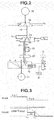
FIG. 2 is a hydraulic circuit showing an configuration of a hydraulic pressure system of an automatic transmission of the electric vehicle according to the embodiment of the present invention. -
FIG. 3 is a time chart showing a characteristic of a control of the electric vehicle according to the embodiment of the present invention. -
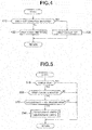
FIG. 4 is a flowchart for explaining a creep torque control of the electric vehicle according to the embodiment of the present invention. -
FIG. 5 is a flowchart for explaining a control in a specific state of the electric vehicle according to the embodiment of the present invention. -
FIG. 6 is a time chart showing a control of the electric vehicle according to the embodiment of the present invention. - Hereinafter, an embodiment according to the present invention is explained with reference to the drawings. Besides, a below-described embodiment is merely example. It is not intended to exclude various variations and applications of the art which are not described in the below-described embodiment. Configurations in the below-described embodiment can be varied as long as they are not deviated from the gist of the invention. Moreover, they can be selected and combined if necessary.
-
FIG. 1 is a configuration view showing a power train (power transmitting system) for an electric vehicle to which a control device according to the embodiment is applied, and that control device. As shown inFIG. 1 , this electric vehicle is a hybrid vehicle including an engine (internal combustion engine) 1; a motor generator (an electric motor with a power generation function) 2; anautomatic transmission 3; afirst clutch 4; asecond clutch 5; a differential gear 6; anddriving wheels - That is, this hybrid vehicle has a power train configuration including the
engine 1, the motor generator (hereinafter, referred also to as MG) 2, and the twoclutches first clutch 4, and an EV mode attained by a disengagement of thefirst clutch 4. - An output shaft of the
engine 1 and an input shaft of MG2 are connected with each other through a first clutch (hereinafter, referred also to as CL1) 4 arranged to vary a torque capacity. Moreover, an output shaft of the MG2 and an input shaft of the automatic transmission (hereinafter, referred also to as AT) 3 are connected with each other. An output shaft of theautomatic transmission 3 is connected through the differential gear 6 to thedriving wheels - The second clutch (hereinafter, referred to also as CL2) 5 is mounted in the
automatic transmission 3. Thesecond clutch 5 is a plurality of frictional engagement elements (clutch or brake) which is arranged to vary a torque capacity, and to be engaged or disengaged in accordance with a gear stage selected in accordance with a traveling state of the vehicle when a shift range is set to a traveling range (for example, a D range, an R range and so on) by an operation of theshift lever 8. - In the HEV mode, the
first clutch 4 is engaged. Theautomatic transmission 3 is arranged to composite (synthesize) a power of theengine 1 which is inputted through thefirst clutch 4, and a power inputted from themotor generator 2, by thesecond clutch 5, and to output the power to thedriving wheels first clutch 4 is disengaged. Theautomatic transmission 3 is arranged to output the power inputted from themotor generator 2 to thedriving wheels second clutch 5. - The
first clutch 4 and thesecond clutch 5 are, for example, wet type multiple plate clutches in which an oil flow rate and a hydraulic pressure can be continuously controlled by proportional solenoid valves. - In the
second clutch 5, a hydraulic passage which is connected to an oil pump 51 (cf.FIG. 2 ) which is a hydraulic source is controlled to be opened and closed in accordance with the selected range by a manual valve 52 (cf.FIG. 2 ) mechanically connected to theshift lever 8. -
FIG. 2 is a hydraulic circuit of a hydraulic pressure supply system for supplying the hydraulic pressure to the low brake which is one of thesecond clutch 5. As shown inFIG. 2 , this hydraulic circuit includes theoil pump 51; themanual valve 52 mechanically connected to theshift lever 8; apressure regulating valve 53 arranged to regulate the hydraulic pressure; a switchingvalve 54; ahydraulic chamber 55 of the low brake; and anoil passage 56 which extends from theoil pump 51 to thehydraulic chamber 55, and in which themanual valve 52, thepressure regulating valve 53, and the switchingvalve 54 are disposed in this order from an upstream side. - Moreover, a
filter 57 is disposed in theoil passage 56 on an outlet side of themanual valve 52. Moreover, theoil passage 56 is bifurcated in parallel manner between thefilter 57 and thepressure regulating valve 53. An orifice 58 (throttling) 58 is disposed in one oil passage. One way valve (check ball) 59 is disposed in the other oil passage. The oneway valve 59 is arranged to allow only a flow of the oil from themanual valve 52 toward thepressure regulating valve 53. The oil rapidly flows from themanual valve 52 side toward thepressure regulating valve 53 side. The oil gently flows from thepressure regulating valve 53 side toward themanual valve 52 side. - When the
shift lever 8 is operated to switch the shift range from the non-traveling range (a P range or an N range) to the traveling range (the R range or the D range) at the stop of the vehicle (stopped state) after the start operation, themanual valve 52 is arranged to supply the oil discharged from theoil pump 51 by the hydraulic pressure level according to the traveling range, to thepressure regulating valve 53 side. In case of the D range, the switchingvalve 54 is brought to the hydraulic pressure supply position by the pilot pressure PP, so that the hydraulic pressure for engaging the low brake is supplied to thehydraulic chamber 55. - In this case, the hydraulic pressure on the
hydraulic chamber 55 side is regulated by thepressure regulating valve 53 in accordance with the low brake command pressure PD supplied to thepressure regulating valve 53. When the command pressure PD is smaller than the actual pressure PR, thepressure regulating valve 53 is brought to a position to drain the hydraulic pressure on thehydraulic chamber 55 side, as shown by a hollow arrow A1. When the command pressure PD is greater than the actual pressure PR, thepressure regulating valve 53 is brought to a position to introduce the hydraulic pressure of the D range pressure supplied from themanual valve 52 to thehydraulic chamber 55 side. Moreover, when the command pressure PD is in a range to be equal to the actual pressure PR, thepressure regulating valve 53 does not connect thehydraulic passage 56 to thehydraulic chamber 55. Moreover, thepressure regulating valve 53 does not drain the hydraulic pressure on thehydraulic chamber 55 side. Thepressure regulating valve 53 is brought to a closing position to hold the hydraulic pressure on thehydraulic chamber 55 side. - In a case where the
shift lever 8 is operated to switch the shift range from the traveling range (the R range or the D range) to the N range of the non-traveling range at the stop of the vehicle, themanual valve 52 is arranged to shut off the supply of the oil discharged from theoil pump 51 to thepressure regulating valve 53 side. Moreover, except for a specific state described later, the pilot pressure PP is removed, and the switchingvalve 54 is brought to a position to drain the hydraulic pressure on thehydraulic chamber 55 side. - Next, a control device for a vehicle provided with the above-described power train is explained.
- As shown in
FIG. 1 , the control device for this vehicle includes a hybrid control module (HCM) 10 configured to control the overall power train; an automatic transmission control unit (ATCU as an automatic transmission control means) 30 configured to control theautomatic transmission 3 under the control of thehybrid control module 10. - The
HCM 10 has functions to perform various controls for the vehicle. In particular, theHCM 10 includes a function (engine control section) 10A configured to control theengine 1; and a function (a motor control section as a motor control means) 10B configured to control themotor generator 2. The HCM is configured to perform the integral control of theengine 1 and themotor generator 2. Furthermore, theHCM 10 includes a function (brake stroke learning section) 12 configured to perform a learning control of the brake stroke. Moreover, theHCM 10 is configured to transmit information relating to the shift, to theATCU 30. - The
HCM 10 is connected to akey switch 90, an inhibitor switch (IHSW) 91, an acceleratoropening degree sensor 92, avehicle speed sensor 94, abrake pressure sensor 95, and so on. Theinhibitor switch 91 is arranged to sense the shift positon of theshift lever 8, and to output the shift range signal according to the shift range. The acceleratoropening degree sensor 92 is arranged to sense an operation amount (accelerator opening degree) of the accelerator pedal. Thevehicle speed sensor 93 is arranged to sense the vehicle speed. Thebrake sensor 94 is arranged to sense an operation amount (brake stroke) of a foot brake. Thebrake pressure sensor 95 is arranged to sense the brake hydraulic pressure. TheHCM 10 receives the detection information of these sensors. - The
motor control section 10B of theHCM 10 includes a creeptorque control section 11 configured to generate the creep torque in themotor generator 2 when a creep torque generation condition is satisfied, and to perform a creep torque cut control to cut the creep torque of themotor generator 2 when a creep cut condition is satisfied even in a case where the creep torque generation condition is satisfied. - The creep torque generation condition is a condition In which the shift range is the traveling range (for example, the D range and the R range), and in which the accelerator pedal Is not operated. The creep
torque control section 11 is configured to judge whether or not this condition is satisfied based on the detection signals of theIHSW 91 and the acceleratoropening degree sensor 92. - Moreover, the creep cut condition is a condition in which the vehicle is stopped, and in which the foot brake is operated. The creep
torque control section 11 is configured to judge whether or not this condition is satisfied based on the detection signals of thevehicle speed sensor 93 and thebrake sensor 94. In a case where the creep cut condition is satisfied, the creep cut control is performed to cut the creep torque even when the creep torque generation condition is satisfied. - The brake
stroke learning section 12 is configured to perform a stroke learning of thebrake sensor 94 when thekey switch 90 is switched to the ON state (READY-On), and the foot brake is operated along the ON state → the OFF state → the ON state. - That is, the stroke learning of the
brake sensor 94 learns the stroke sensor value (0 point, brake joint point) at which the brake hydraulic pressure is started to be increased by the depression of the brake pedal to start to apply (act) the brake, and the stroke sensor value at which the brake hydraulic pressure is decreased to be zero by the depression release (return) of the brake pedal. It is possible to obtain the brake hydraulic pressure at this time as the detection value from thebrake pressure sensor 95. - Accordingly, the stroke sensor value at which the brake is started to be applied is stored at the depression of the brake pedal by which the foot brake is operated from the OFF state to the ON state. The stroke sensor value at which the brake hydraulic pressure is decreased to zero is stored at the depression release of the brake pedal by which the foot brake is switched from the ON state to the OFF state after the above-described state. Then, when the foot brake is switched from the OFF state to the ON state, the 0 point of the brake sensor (the stroke sensor) 94 is calculated based on the stored stroke sensor values, and updated and stored.
- The brake
stroke learning section 12 is configured to learn and update the stroke sensor value at every timings when thekey switch 90 is operated to the ON state. With this, it is possible to appropriately grasp (know) the operation state of the brake from the signal sensed by thebrake sensor 94. - Moreover, the
HCM 10 is configured to make the output of thebrake sensor 94 invalid until the 0 point of thebrake sensor 94 is updated after the brakestroke learning section 12 finishes the learning after thekey switch 90 is switched to the ON state. That is, the only information of the stroke sensor value which is learned and updated is valid. With this, the operation state of the brake is not inappropriately grasped from the detection signal from the detection signal of thebrake sensor 94 which is the signal before the learning and the update. - The control device is configured to perform a specific control relating to the creep torque of the
motor generator 2. That is, when the shift range is switched from the traveling range to the non-traveling range in the specific state where the creep torque is generated in themotor generator 2 in the stop state of the electric vehicle in the engagement state of thesecond clutch 5, the motor control section 10b is configured to perform the torque decrease control by which the creep torque of themotor generator 2 is stepwisely decreased. Moreover, theATCU 30 is configured to perform the disengagement control by which thesecond clutch 5 is gently disengaged. - It is supposed that the specific state is a state where the key switch of the vehicle is switched to the ON state, and the
shift lever 8 is operated to slowly switch the shift range from the P range through the R range to the N range in a state where the brake pedal is depressed (of course, the accelerator pedal is not operated). - Besides, it is possible to suppose, as the specific state, a state where the
shift lever 8 is operated to rapidly switch the shift range through the P range, the R range, and the N range to the D range, and then to switch to the N range in a state where the brake pedal is depressed without operating the accelerator pedal. - In these cases, the foot brake is held to the ON state after the operation of the start of the vehicle. Accordingly, the brake
stroke learning section 12 does not perform the stroke learning yet. Consequently, the detection signal of the brake sensor 94 (the brake operation detection signal, abbreviated as the brake signal) is made invalid. - In this state, the creep torque generation condition is satisfied while the shift range is in the traveling range of the R range and the D range, and the creep cut condition is not satisfied. Accordingly, the
motor control section 10B generates the creep torque to themotor generator 2 while the shift range Is In the traveling range. In this case, when the shift range is switched from the traveling range to the N range of the non-traveling range, the creep torque generation condition is not satisfied. Accordingly, the creep torque is cut. TheATCU 30 disengages thesecond clutch 5 of theautomatic transmission 3 in accordance with the non-traveling range. - Conventionally, the creep torque cut and the disengagement of the
second clutch 5 at this time are immediately performed. In this control device, themotor control section 10B stepwisely decreases the creep torque by the torque decrease control. TheATCU 30 gently disengages thesecond clutch 5 by the disengagement control. - In the above-described specific state, the creep torque is stored in the power train while the shift range is in the traveling range. Accordingly, in a case where the instantaneous creep torque cut and the instantaneous disengagement of the
second clutch 5 are performed in accordance with the switching to the non-traveling, the forward and rearward G variation is generated due to the torque stored in the power train to provide the large unnatural feeling to the driver. The above-described control is performed for avoiding this. -
FIG. 3 is a time chart for explaining the torque decrease control and the disengagement control in this embodiment. - In the toque decrease control, the creep torque is decreased in the two step manner, as shown in
FIG. 3 . That is, at time tS1 when the shift range is switched to the non-traveling range, the creep torque is decreased to the half in a first step decrease. At time tS2 after a predetermined time period, the creep torque is decreased to zero in a second step decrease. - In the disengagement control, the
second clutch 5 is gently disengaged in parallel with this torque decrease control while ensuring the transmission torque capacity greater than the decreased creep torque. In particular, it is supposed that a hydraulic pressure variation characteristic is a characteristic in which the actual pressure PR of thehydraulic chamber 55 is gradually decreased by the leakage in a state where themanual valve 52 is in the open positon in accordance with the switching of shift range to the N range. The command pressure PD corresponding to this hydraulic pressure variation characteristic is provided to thepressure regulating valve 53. With this, it is possible to gently disengage thesecond clutch 5 while ensuring the transmission torque capacity greater than the creep torque. - When the command pressure PD of the
pressure regulating valve 53 is in the region to be equal to the actual pressure PR, thepressure regulating valve 53 is in the closing positon to close thehydraulic passage 56. That Is, thepressure regulating valve 53 suppress the discharge of the hydraulic pressure on thehydraulic chamber 55 side from themanual valve 52 which is in the open position through thehydraulic passage 56. Moreover, thepressure regulating valve 53 does not drain the hydraulic pressure on thehydraulic chamber 55 side. Accordingly, the decrease of the hydraulic pressure on thehydraulic chamber 55 side is suppressed to the leakage amount from thepressure regulating valve 53. Accordingly, it is possible to gently disengage thesecond clutch 5 while ensuring the transmission torque capacity greater than the creep torque. Besides, in this specific state, the pilot pressure PP is held to hold the switchingvalve 54 to the hydraulic pressure supply position even when theselect lever 8 becomes the non-traveling range, so that the connection between thehydraulic chamber 55 and thepressure regulating valve 53 is ensured. Accordingly, when the command pressure PD is smaller than the actual pressure PR, the hydraulic pressure on thehydraulic chamber 55 side is gently decreased in the path connected to theorifice 58, as shown by a hollow arrow A2 ofFIG. 2 . However, when the command pressure PD of thepressure regulating valve 53 is in the region to be equal to the actual pressure PR, thepressure regulating valve 53 is in the closing positon, so that the hydraulic pressure on thehydraulic chamber 55 side is further gently decreased relative to the above-described case. - As shown in
FIG. 3 , the actual pressure PR is decreased in the stepped manner by the minute amount at the time tS1 when themanual valve 52 is brought to the open position. Accordingly, the command pressure PD is decreased in the stepped manner by the minute amount. Thereafter, the command pressure PD is decreased by a linear inclination. However, the linear inclination is slightly increased near the time tS2 when the second stepped decrease of the creep torque is performed. This is because it is possible to finish the disengagement of thesecond clutch 5 at the early timing since there is little influence to the suppress of the forward and rearward G variation even when the disengagement speed of thesecond clutch 5 is slightly increased near the time tS2. - Besides, while the torque decrease control and the disengagement control are performed in a case where the shift range is switched from one of the traveling ranges of the D range and the R range to the N range, the
motor control section 10B and theATCU 30 stop the torque decrease control and the disengagement control to immediately bring the creep torque of themotor generator 2 to zero, and to immediately disengage thesecond clutch 5 when the shift range is switched from the N range to the other of the traveling ranges of the D range and the R range. Furthermore, when the shift range is switched (returned) to the same traveling range (the one of the traveling ranges), themotor control section 10B and theATCU 30 similarly stop the torque decrease control and the disengagement control to immediately bring the creep torque of themotor generator 2 to zero, and to immediately disengage thesecond clutch 5. - The control device for the electric vehicle according to the one embodiment of the present invention is constructed as described above. For example, the creep torque cut control is performed as shown in
FIG. 4 , and the torque decrease control and the disengagement control are performed as shown inFIG. 5 . Besides, the operations ofFIG. 4 and FIG. 5 are started when the key switch of the vehicle is operated to the ON state, and finished when the key switch of the vehicle is operated to the OFF state. The operations ofFIG. 4 and FIG. 5 are performed at a predetermined control cycle. - In the creep torque control cut, it is judged whether or not the creep cut condition is satisfied (step A10), as shown in
FIG. 4 , in a case where the creep torque is applied. In particular, it is judged whether or not the vehicle is stopped, and the foot brake is operated in a state where the shift range is in the traveling range and the accelerator pedal is not operated. - In this case, when the creep cut condition is satisfied, the creep torque is not generated (the creep torque cut) (step A30). On the other hand, when the creep cut condition is not satisfied, the creep torque is generated in the motor generator 2 (step 20).
- Moreover, in the torque decrease control and the disengagement control, it is firstly judged whether or not the vehicle is stopped from the information of the
vehicle speed sensor 93, as shown inFIG. 5 (step B10, judgment step). When the vehicle is not stopped, the process is returned. When the vehicle is stopped, it is judged whether or not the creep torque is generated from the control information of themotor control section 10B (step B20, the judgment step). In this case, when the creep torque is not generated, the process is returned. - On the other hand, in a case where it is judged that the creep torque is generated at step B20, it is the specific state where the vehicle is stopped and the creep torque is generated. In this specific state, the creep torque is stored in the power train. Next, it is judged whether or not the shift range is switched from the traveling range to the non-traveling range (step B30). When the shift range is not switched from the traveling range to the non-traveling range, the process is returned.
- On the other hand, when it is judged that the shift range is switched from the traveling range to the non-traveling range at step B30, the torque decrease control to stepwisely decrease the creep torque of the
motor generator 2 is performed. The automatic transmission control means performs the disengagement control to gently disengage the second clutch 5 (step B40, a control step). -
FIG. 6 is a time chart showing the control of the electric vehicle according to the embodiment. The torque decrease control and the disengagement control in the specific state are explained with reference toFIG. 6 . - As shown in
FIG. 6 , the foot brake is operated at time t1 (the ON state). The key switch is operated to the ON state at time t2 while the above-described state is maintained. Then, when the shift range is switched from the non-traveling range (the P range or the N range) to the traveling range (the R range or the D range) at time t3, the creep torque generation condition is satisfied, so that the creep torque is generated. While the brake is continued to be operated, the output of thebrake sensor 94 is invalid, so that the creep cut condition is not satisfied. Moreover, the vehicle is maintained in the stop state. - Then, the shift range is switched from the traveling range to the non-traveling range at time t4. The torque decrease control to stepwisely decrease the creep torque is performed from the time t4. Moreover, the disengagement control to gently disengage the
second clutch 5 is performed. In this embodiment, the creep torque is decreased to the half at the time t4. The creep torque is decreased to zero at time t5. Furthermore, in the disengagement control, as shown as the clutch pressure, thesecond clutch 5 is gently disengaged from time t4 to time t5 by the gentle inclination, and gently disengaged from time t5 by the steeper inclination angle slightly steeper than the gentle inclination, while ensuring the transmission torque capacity to be greater than the decreased creep torque. - Besides, for example, when the foot brake is released at time t6 as shown by two dot chain line of
FIG. 6 , the vehicle is started to be moved (cf. the vehicle speed shown by the two dot chain line). Then, when the foot brake is operated again at time t7 as shown by the two dot chain line, the learning control of thebrake sensor 94 is performed. The output of thebrake sensor 94 becomes valid (effective). As shown after time t7, the brake signal is outputted in accordance with the hydraulic pressure. The creep cut condition is satisfied. The creep torque is cut to zero. At this time, thesecond clutch 5 is held to the engagement state. The forward and rearward G variation of the vehicle is not generated. - As described above, in a case where the creep torque of the
motor generator 2 is immediately brought to zero and thesecond clutch 5 is immediately disengaged when the shift range is switched from the traveling range to the non-traveling range in the specific state where the creep torque is stored in the power train, the creep torque stored in the power train is immediately released. With this, the forward and rearward G variation of the vehicle may be generated to provide the unnatural feeling to the driver and the occupant of the vehicle. However, in the device according to the present invention, the creep torque is stepwisely decreased so that thesecond clutch 5 is gently disengaged. Accordingly, it is possible to suppress the generation of the forward and rearward G variation of the vehicle, and to suppress the possibility of the unnatural feeing to the driver and the occupant of the vehicle. - In the torque decrease control according to this embodiment, the creep torque is decreased in the two stepped manner. Accordingly, it is possible to suppress the generation of the forward and rearward G variation of the vehicle by the simple control.
- Moreover, in the disengagement control performed in parallel with this torque decrease control, the
second clutch 5 is gently disengaged while ensuring the transmission torque capacity to be greater than the decreased creep torque. Accordingly, at least in a first half of the disengagement control, it is possible to suppress the release of the creep torque in thesecond clutch 5. This release of the creep torque in thesecond clutch 5 is a large cause of the generation of the forward and rearward G of the vehicle. However, it is possible to surely suppress the generation of the forward and rearward G variation of the vehicle. - Besides, In this case, it is supposed that the specific state is generated since the brake signal before the learning control of the brake sensor is invalid. However, the specific state is a state where the vehicle is stopped and the creep torque is generated. This state is not limited to the state where the brake signal before the learning control of the brake sensor is invalid. Even when the specific state is generated due to any causes, in a case where the creep torque of the
motor generator 2 is immediately brought to zero and thesecond clutch 5 is immediately disengaged when the shift range is switched from the traveling range to the non-traveling range in the specific state, the generation of the forward and rearward G variation may be caused to provide the unnatural feeing. Accordingly, it is effective to employ the torque decrease control and the disengagement control according to the present invention. - However, the torque decrease control and the disengagement control may be applied only to a case where the specific state is generated since the brake signal before the learning control of the brake sensor is invalid, by limiting the specific state to the timing before the learning control of the brake sensor.
- Hereinbefore, the embodiment according to the present invention is explained. However, the present invention is not limited to the above-described embodiment. Various variations of the embodiment are applicable as long as it is not deviated from the gist of the present invention.
- For example, in the above-described embodiment, when the shift range is switched from the traveling range to the non-traveling range in the specific state where the vehicle is stopped and the creep torque is generated, the torque decrease control and the disengagement control are performed. However, when the specific state is during a short time period, the storage of the creep torque is small. Accordingly, the generation of the forward and rearward G variation of the vehicle may be small, so that there is no problem. In consideration of the above-described case, the torque decrease control and the disengagement control may be performed in a case where the shift range is switched from the traveling range to the non-traveling range when the specific state is continued during a predetermined time period or more.
- Furthermore, in the above-described embodiment, the electric vehicle is the hybrid vehicle using the engine and the electric motor as the power source. The electric vehicle according to the present invention may be an electric vehicle using the only electric motor as the power source,.
- Moreover, in the above-described embodiment, the frictional engagement element is the hydraulically-actuated clutch. The present invention is applicable to any frictional engagement elements such as an electromagnetic frictional engagement element as long as it is the frictional engagement element arranged to vary the transmission torque capacity.
- Besides, in the above-described embodiment, in the torque decrease control, the creep torque of the electric motor is decreased in the two step manner. However, in the torque decrease control, it is sufficient that the creep torque of the electric motor is stepwisely decreased. In the torque decrease control, the creep torque of the electric motor may be decreased in multiple step manner as long as the creep torque is gradually decreased.
Claims (7)
- A control device for an electric vehicle including an electric motor, and an automatic transmission including a frictional engagement element disposed in a power transmitting system between the electric motor and a driving wheel, and arranged to connect and disconnect a power, the control device comprising:a motor control means configured to generate a creep torque in the electric motor when a creep torque generation condition is satisfied, and to cut the creep torque when a creep cut condition is satisfied even when the creep torque generation condition is satisfied;a range selection means configured to select a shift range of the automatic transmission; andan automatic transmission control means configured to bring the frictional engagement element to an engagement state when a traveling range is selected in the range selection means, and to bring the frictional engagement element to a disengagement state when a non-traveling range is selected in the range selection means,the creep torque generation condition being a condition in which the shift range is the traveling range and the accelerator pedal is not operated,the creep cut condition being a condition in which the vehicle is stopped and a brake sensor outputs a brake operation detection signal, andwhen the shift range is switched from the traveling range to the non-traveling range in a specific state where the electric vehicle is in a stop state and the creep torque is generated in the electric motor, the motor control means being configured to perform a torque decrease control to stepwisely decrease the creep torque of the electric motor, and the automatic transmission control means being configured to perform a disengagement control to gently disengage the frictional engagement element.
- The control device for the electric vehicle as claimed in claim 1, wherein the automatic transmission control means is configured to perform the disengagement control while ensuring a transmission torque capacity to be greater than the decreased creep torque of the electric motor when the motor control means performs the torque decrease control.
- The control device for the electric vehicle as claimed in claim 1 or 2, wherein the motor control means is configured to decrease the creep torque of the electric motor in a two step manner, to decrease the creep torque to a half in a first step, and to decrease the creep torque to zero in a second step.
- The control device for the electric vehicle as claimed in one of claims 1 to 3, wherein the control device comprises a brake characteristic update means configured to learn and update an output characteristic of the brake senor in accordance with a predetermined operation of the foot brake which is performed after a start operation of the electric vehicle; and the brake characteristic update means is configured to make the output of the brake sensor invalid until the brake characteristic update means learns and updates the output of the brake sensor after the start operation.
- The control device for the electric vehicle as claimed in one of claims 1 to 4, wherein the frictional engagement element is a hydraulically actuated element arranged to be actuated by a hydraulic pressure supplied to and discharged from a hydraulic chamber; a manual valve and a pressure regulating valve are provided in this order from an upstream side in a hydraulic passage arranged to supply the hydraulic pressure from a hydraulic pressure source to the hydraulic chamber; the manual valve is mechanically connected to the shift lever; the pressure regulating valve is arranged to regulate an actual pressure of the oil within the hydraulic chamber in accordance with a command pressure; and the automatic transmission control means is configured to perform the disengagement control to decrease the actual pressure by providing the command pressure according to the variation characteristic of the actual pressure by which the frictional engagement element is gently disengaged.
- The control device for the electric vehicle as claimed in one of claims 1 to 5, wherein in a case where the shift range is switched from one of forward and rearward traveling ranges to the non-traveling range, the torque decrease control and the disengagement control are stopped to immediately bring the creep torque of the electric motor to zero, and the frictional engagement element is disengaged when the shift range is switched from the non-traveling range to the other of the forward and rearward traveling ranges.
- A control method for an electric vehicle including an electric motor, and an automatic transmission including a frictional engagement element disposed in a power transmitting system between the electric motor and a driving wheel, and arranged to connect and disconnect a power, the control method comprising:a motor control configured to generate a creep torque in the electric motor when a creep torque generation condition is satisfied, and to cut the creep torque when a creep cut condition is satisfied even when the creep torque generation condition is satisfied;an automatic transmission control configured to bring the frictional engagement element to an engagement state when a traveling range is selected in the range selection means configured to select a shift range of the automatic transmission, and to bring the frictional engagement element to a disengagement state when a non-traveling range is selected in the range selection means,the creep torque generation condition being a condition in which the shift range is the traveling range and the accelerator pedal is not operated, andthe creep cut condition being a condition in which the vehicle is stopped and a brake sensor outputs a brake operation detection signal,a judgment step of judging whether or not the vehicle is in a specific state where the creep torque is generated in the electric motor in an engagement state of the frictional engagement element in a stop state of the electric vehicle; anda control step of stepwisely decreasing the creep torque of the electric motor, and performing a disengagement control to gently disengage the frictional engagement element when the shift range is switched from the traveling range to the non-traveling range in the specific state.
Applications Claiming Priority (2)
| Application Number | Priority Date | Filing Date | Title |
|---|---|---|---|
| JP2015230721A JP6653556B2 (en) | 2015-11-26 | 2015-11-26 | Control device and control method for electric vehicle |
| PCT/JP2016/083739 WO2017090479A1 (en) | 2015-11-26 | 2016-11-15 | Electric-vehicle control device and control method |
Publications (3)
| Publication Number | Publication Date |
|---|---|
| EP3381739A1 true EP3381739A1 (en) | 2018-10-03 |
| EP3381739A4 EP3381739A4 (en) | 2019-05-01 |
| EP3381739B1 EP3381739B1 (en) | 2022-01-05 |
Family
ID=58764084
Family Applications (1)
| Application Number | Title | Priority Date | Filing Date |
|---|---|---|---|
| EP16868427.2A Active EP3381739B1 (en) | 2015-11-26 | 2016-11-15 | Electric-vehicle control device and control method |
Country Status (6)
| Country | Link |
|---|---|
| US (1) | US10569661B2 (en) |
| EP (1) | EP3381739B1 (en) |
| JP (1) | JP6653556B2 (en) |
| KR (1) | KR20180038028A (en) |
| CN (1) | CN108025657B (en) |
| WO (1) | WO2017090479A1 (en) |
Families Citing this family (17)
| Publication number | Priority date | Publication date | Assignee | Title |
|---|---|---|---|---|
| US11359717B2 (en) * | 2016-08-03 | 2022-06-14 | Jatco Ltd. | Select control device of automatic transmission |
| CN107512197A (en) * | 2017-08-21 | 2017-12-26 | 合肥翔望智能科技有限公司 | A kind of electric car starting abnormal sound control method |
| KR102555909B1 (en) * | 2018-06-28 | 2023-07-17 | 현대자동차주식회사 | Vehicle equipped with electric motor and method for parking control thereof |
| KR102545103B1 (en) * | 2018-08-07 | 2023-06-19 | 현대자동차주식회사 | Vehicle equipped with electric motor and method for parking control thereof |
| CN109591621B (en) * | 2018-12-10 | 2021-03-26 | 北京新能源汽车股份有限公司 | Method, device, vehicle and medium for preventing vehicle from sliding on ramp |
| US11589958B2 (en) | 2019-12-31 | 2023-02-28 | Joseph Yousefian | Pharyngorofacial expander appliance and protocol |
| CN110985661A (en) * | 2020-03-04 | 2020-04-10 | 盛瑞传动股份有限公司 | Control method for oil pressure of automatic hydraulic torque converter during gear shifting cancellation |
| CN111348031B (en) * | 2020-03-27 | 2021-04-27 | 浙江吉利汽车研究院有限公司 | A control method and system for a hybrid vehicle |
| JP7485463B2 (en) * | 2020-06-03 | 2024-05-16 | 株式会社Subaru | Driving Support Devices |
| CN112109714B (en) * | 2020-09-28 | 2022-01-28 | 北京车和家信息技术有限公司 | Vehicle forward gear neutral gear switching torque control method and device and vehicle |
| DE102021105340A1 (en) | 2021-03-05 | 2022-09-08 | Bayerische Motoren Werke Aktiengesellschaft | Drive control system for a motor vehicle that can be operated by an electric motor, with a gear selector |
| CN114643964B (en) * | 2021-04-08 | 2023-07-21 | 长城汽车股份有限公司 | Vehicle braking method, device, storage medium and vehicle |
| CN113833839A (en) * | 2021-09-29 | 2021-12-24 | 上万清源智动车有限公司 | Electric automobile gear control management method |
| CN115648969B (en) * | 2022-11-09 | 2025-06-10 | 北汽福田汽车股份有限公司 | Vehicle control method, device, storage medium, electronic device and vehicle |
| JP7854465B2 (en) * | 2024-03-12 | 2026-05-01 | ダイハツ工業株式会社 | Vehicle control system |
| CN118876744B (en) * | 2024-09-30 | 2025-01-03 | 张家港长城汽车研发有限公司 | Torque control method in creep mode, electronic device and vehicle |
| CN119099364A (en) * | 2024-09-30 | 2024-12-10 | 长城汽车股份有限公司 | Torque control method for dynamic shifting, electronic equipment and vehicle |
Family Cites Families (22)
| Publication number | Priority date | Publication date | Assignee | Title |
|---|---|---|---|---|
| JPH09191507A (en) * | 1996-01-11 | 1997-07-22 | Honda Motor Co Ltd | Control device for electric vehicle |
| JP2002089678A (en) * | 2000-09-14 | 2002-03-27 | Nissan Motor Co Ltd | Control device for continuously variable transmission with infinite transmission ratio |
| JP4297135B2 (en) * | 2006-05-29 | 2009-07-15 | トヨタ自動車株式会社 | Control device for vehicle drive device |
| JP4059283B2 (en) * | 2006-08-25 | 2008-03-12 | トヨタ自動車株式会社 | Vehicle control apparatus, hybrid vehicle, vehicle control method, program for causing computer to execute vehicle control method, and computer-readable recording medium recording the program |
| JP4410261B2 (en) * | 2007-01-25 | 2010-02-03 | 本田技研工業株式会社 | Vehicle control device |
| JP5195257B2 (en) * | 2008-10-10 | 2013-05-08 | トヨタ自動車株式会社 | Vehicle control apparatus and control method |
| JP5521834B2 (en) * | 2010-06-30 | 2014-06-18 | 日産自動車株式会社 | Creep cut control device for electric vehicle |
| JP5516268B2 (en) * | 2010-09-17 | 2014-06-11 | 三菱自動車工業株式会社 | Vehicle motor torque control device |
| JP5381954B2 (en) * | 2010-10-20 | 2014-01-08 | 三菱自動車工業株式会社 | Vehicle driving force control device |
| JP5496854B2 (en) * | 2010-11-01 | 2014-05-21 | ジヤトコ株式会社 | Vehicle control device |
| JP5737500B2 (en) * | 2011-01-31 | 2015-06-17 | 日立オートモティブシステムズ株式会社 | Electric brake device |
| JP5434946B2 (en) * | 2011-03-30 | 2014-03-05 | アイシン・エィ・ダブリュ株式会社 | Hydraulic control device |
| EP2781393B1 (en) * | 2011-11-14 | 2018-02-21 | Toyota Jidosha Kabushiki Kaisha | Vehicle |
| DE102012015617A1 (en) * | 2012-08-07 | 2014-02-13 | Daimler Ag | Method for regulating creeping operation of motor vehicle device, involves generating driving torque in creeping operation, and controlling brake parameter of service brake unit for adjusting braking effect in operating condition |
| DE102012015872A1 (en) * | 2012-08-09 | 2014-05-15 | Volkswagen Aktiengesellschaft | Circuit, method and computer program for controlling a creep mode |
| JP5971345B2 (en) * | 2012-09-28 | 2016-08-17 | アイシン・エィ・ダブリュ株式会社 | Control device for hybrid vehicle |
| JP5993357B2 (en) * | 2013-09-13 | 2016-09-14 | ジヤトコ株式会社 | Vehicle control device |
| JP6201210B2 (en) * | 2013-09-24 | 2017-09-27 | 日立オートモティブシステムズ株式会社 | Electric vehicle control device and electric vehicle control method |
| US10293810B2 (en) * | 2013-10-18 | 2019-05-21 | Ford Global Technologies, Llc | Hybrid vehicle idle and creep control |
| JP6710962B2 (en) * | 2015-12-22 | 2020-06-17 | 三菱自動車工業株式会社 | Control device for electric vehicle |
| US10112613B2 (en) * | 2016-02-12 | 2018-10-30 | Ford Global Technologies, Llc | Systems and methods for managing torque |
| US10308138B2 (en) * | 2016-05-11 | 2019-06-04 | Ford Global Technologies, Llc | Hybrid electric vehicle creep control |
-
2015
- 2015-11-26 JP JP2015230721A patent/JP6653556B2/en active Active
-
2016
- 2016-11-15 EP EP16868427.2A patent/EP3381739B1/en active Active
- 2016-11-15 US US15/759,395 patent/US10569661B2/en active Active
- 2016-11-15 CN CN201680052962.9A patent/CN108025657B/en active Active
- 2016-11-15 WO PCT/JP2016/083739 patent/WO2017090479A1/en not_active Ceased
- 2016-11-15 KR KR1020187006616A patent/KR20180038028A/en not_active Ceased
Also Published As
| Publication number | Publication date |
|---|---|
| JP2017099192A (en) | 2017-06-01 |
| US10569661B2 (en) | 2020-02-25 |
| KR20180038028A (en) | 2018-04-13 |
| EP3381739B1 (en) | 2022-01-05 |
| CN108025657B (en) | 2020-11-06 |
| CN108025657A (en) | 2018-05-11 |
| US20180264973A1 (en) | 2018-09-20 |
| JP6653556B2 (en) | 2020-02-26 |
| EP3381739A4 (en) | 2019-05-01 |
| WO2017090479A1 (en) | 2017-06-01 |
Similar Documents
| Publication | Publication Date | Title |
|---|---|---|
| EP3381739B1 (en) | Electric-vehicle control device and control method | |
| KR101393970B1 (en) | Breakdown control device upon jamming of automatic transmission | |
| EP2418401B1 (en) | Vehicle, vehicle control method and control device | |
| KR101404379B1 (en) | Hydraulic control device for automatic transmission | |
| US8589041B2 (en) | Control device and control method for vehicle | |
| EP1475556A2 (en) | Method and system for controlling a vehicle | |
| US10281032B2 (en) | Transmission gear control apparatus for vehicle | |
| JP5841584B2 (en) | Powertrain control device | |
| US20080058158A1 (en) | Control device and control method for vehicle | |
| CN104024700A (en) | Automatic transmission and its control method when starting | |
| KR101472247B1 (en) | Automatic transmission control device | |
| CN105460000B (en) | For the control system of vehicle | |
| US7291092B2 (en) | Shift control apparatus and method for automatic transmission | |
| JP2010091063A (en) | Shift control method and shift control device for vehicular automatic transmission | |
| JP6935768B2 (en) | Automatic transmission control device | |
| US20080300106A1 (en) | Control device for vehicular automatic transmission | |
| US9031751B2 (en) | Device for controlling automatic transmission | |
| US20110246037A1 (en) | Hydraulic control apparatus for lockup clutch | |
| US8249784B2 (en) | Control apparatus and control method for automatic transmission | |
| CN103836182A (en) | Control system and method for belt type CVT equipped with hydraulic torque converter | |
| KR101793075B1 (en) | Method and apparatus for controlling automatic transmission | |
| JP7268456B2 (en) | automatic transmission controller | |
| KR20080053150A (en) | Method for controlling shifting during shifting and system thereof | |
| JP2009168215A (en) | Vehicle control apparatus and control method | |
| JP5402422B2 (en) | Control device for automatic transmission and control method for automatic transmission |
Legal Events
| Date | Code | Title | Description |
|---|---|---|---|
| STAA | Information on the status of an ep patent application or granted ep patent |
Free format text: STATUS: THE INTERNATIONAL PUBLICATION HAS BEEN MADE |
|
| PUAI | Public reference made under article 153(3) epc to a published international application that has entered the european phase |
Free format text: ORIGINAL CODE: 0009012 |
|
| STAA | Information on the status of an ep patent application or granted ep patent |
Free format text: STATUS: REQUEST FOR EXAMINATION WAS MADE |
|
| 17P | Request for examination filed |
Effective date: 20180309 |
|
| AK | Designated contracting states |
Kind code of ref document: A1 Designated state(s): AL AT BE BG CH CY CZ DE DK EE ES FI FR GB GR HR HU IE IS IT LI LT LU LV MC MK MT NL NO PL PT RO RS SE SI SK SM TR |
|
| AX | Request for extension of the european patent |
Extension state: BA ME |
|
| RIC1 | Information provided on ipc code assigned before grant |
Ipc: F16H 63/50 20060101ALI20170622BHEP Ipc: B60K 6/54 20071001ALI20170622BHEP Ipc: B60K 6/48 20071001ALI20170622BHEP Ipc: B60L 15/20 20060101AFI20170622BHEP Ipc: B60W 10/02 20060101ALI20170622BHEP Ipc: F16H 59/08 20060101ALI20170622BHEP Ipc: F16H 59/22 20060101ALI20170622BHEP Ipc: F16H 61/02 20060101ALI20170622BHEP Ipc: B60L 11/14 20060101ALI20170622BHEP Ipc: F16H 59/54 20060101ALI20170622BHEP Ipc: F16H 61/06 20060101ALI20170622BHEP Ipc: B60T 7/02 20060101ALI20170622BHEP Ipc: B60W 10/08 20060101ALI20170622BHEP |
|
| DAV | Request for validation of the european patent (deleted) | ||
| DAX | Request for extension of the european patent (deleted) | ||
| A4 | Supplementary search report drawn up and despatched |
Effective date: 20190402 |
|
| RIC1 | Information provided on ipc code assigned before grant |
Ipc: B60K 6/54 20071001ALI20190327BHEP Ipc: B60W 10/08 20060101ALI20190327BHEP Ipc: B60T 7/02 20060101ALI20190327BHEP Ipc: B60W 50/02 20120101ALI20190327BHEP Ipc: B60K 6/48 20071001ALI20190327BHEP Ipc: F16H 59/08 20060101ALI20190327BHEP Ipc: B60W 10/10 20120101ALI20190327BHEP Ipc: B60W 30/18 20120101ALI20190327BHEP Ipc: B60W 10/02 20060101ALI20190327BHEP Ipc: B60W 30/02 20120101ALI20190327BHEP Ipc: B60L 15/20 20060101AFI20190327BHEP Ipc: B60W 20/50 20160101ALI20190327BHEP Ipc: F16H 59/22 20060101ALI20190327BHEP Ipc: F16H 61/02 20060101ALI20190327BHEP Ipc: F16H 61/06 20060101ALI20190327BHEP Ipc: F16H 59/54 20060101ALI20190327BHEP Ipc: F16H 63/50 20060101ALI20190327BHEP |
|
| GRAP | Despatch of communication of intention to grant a patent |
Free format text: ORIGINAL CODE: EPIDOSNIGR1 |
|
| STAA | Information on the status of an ep patent application or granted ep patent |
Free format text: STATUS: GRANT OF PATENT IS INTENDED |
|
| RIC1 | Information provided on ipc code assigned before grant |
Ipc: B60L 15/20 20060101AFI20210602BHEP Ipc: B60K 6/48 20071001ALI20210602BHEP Ipc: B60K 6/54 20071001ALI20210602BHEP Ipc: B60T 7/02 20060101ALI20210602BHEP Ipc: B60W 10/02 20060101ALI20210602BHEP Ipc: B60W 10/08 20060101ALI20210602BHEP Ipc: F16H 59/08 20060101ALI20210602BHEP Ipc: F16H 59/22 20060101ALI20210602BHEP Ipc: F16H 59/54 20060101ALI20210602BHEP Ipc: F16H 61/02 20060101ALI20210602BHEP Ipc: F16H 61/06 20060101ALI20210602BHEP Ipc: F16H 63/50 20060101ALI20210602BHEP Ipc: B60W 10/10 20120101ALI20210602BHEP Ipc: B60W 30/18 20120101ALI20210602BHEP Ipc: B60W 30/02 20120101ALI20210602BHEP Ipc: B60W 20/50 20160101ALI20210602BHEP Ipc: B60W 50/02 20120101ALI20210602BHEP |
|
| INTG | Intention to grant announced |
Effective date: 20210705 |
|
| GRAS | Grant fee paid |
Free format text: ORIGINAL CODE: EPIDOSNIGR3 |
|
| GRAA | (expected) grant |
Free format text: ORIGINAL CODE: 0009210 |
|
| STAA | Information on the status of an ep patent application or granted ep patent |
Free format text: STATUS: THE PATENT HAS BEEN GRANTED |
|
| AK | Designated contracting states |
Kind code of ref document: B1 Designated state(s): AL AT BE BG CH CY CZ DE DK EE ES FI FR GB GR HR HU IE IS IT LI LT LU LV MC MK MT NL NO PL PT RO RS SE SI SK SM TR |
|
| REG | Reference to a national code |
Ref country code: GB Ref legal event code: FG4D |
|
| REG | Reference to a national code |
Ref country code: CH Ref legal event code: EP |
|
| REG | Reference to a national code |
Ref country code: AT Ref legal event code: REF Ref document number: 1460233 Country of ref document: AT Kind code of ref document: T Effective date: 20220115 |
|
| REG | Reference to a national code |
Ref country code: DE Ref legal event code: R096 Ref document number: 602016068188 Country of ref document: DE |
|
| REG | Reference to a national code |
Ref country code: IE Ref legal event code: FG4D |
|
| REG | Reference to a national code |
Ref country code: LT Ref legal event code: MG9D |
|
| REG | Reference to a national code |
Ref country code: NL Ref legal event code: MP Effective date: 20220105 |
|
| REG | Reference to a national code |
Ref country code: AT Ref legal event code: MK05 Ref document number: 1460233 Country of ref document: AT Kind code of ref document: T Effective date: 20220105 |
|
| PG25 | Lapsed in a contracting state [announced via postgrant information from national office to epo] |
Ref country code: NL Free format text: LAPSE BECAUSE OF FAILURE TO SUBMIT A TRANSLATION OF THE DESCRIPTION OR TO PAY THE FEE WITHIN THE PRESCRIBED TIME-LIMIT Effective date: 20220105 |
|
| PG25 | Lapsed in a contracting state [announced via postgrant information from national office to epo] |
Ref country code: SE Free format text: LAPSE BECAUSE OF FAILURE TO SUBMIT A TRANSLATION OF THE DESCRIPTION OR TO PAY THE FEE WITHIN THE PRESCRIBED TIME-LIMIT Effective date: 20220105 Ref country code: RS Free format text: LAPSE BECAUSE OF FAILURE TO SUBMIT A TRANSLATION OF THE DESCRIPTION OR TO PAY THE FEE WITHIN THE PRESCRIBED TIME-LIMIT Effective date: 20220105 Ref country code: PT Free format text: LAPSE BECAUSE OF FAILURE TO SUBMIT A TRANSLATION OF THE DESCRIPTION OR TO PAY THE FEE WITHIN THE PRESCRIBED TIME-LIMIT Effective date: 20220505 Ref country code: NO Free format text: LAPSE BECAUSE OF FAILURE TO SUBMIT A TRANSLATION OF THE DESCRIPTION OR TO PAY THE FEE WITHIN THE PRESCRIBED TIME-LIMIT Effective date: 20220405 Ref country code: LT Free format text: LAPSE BECAUSE OF FAILURE TO SUBMIT A TRANSLATION OF THE DESCRIPTION OR TO PAY THE FEE WITHIN THE PRESCRIBED TIME-LIMIT Effective date: 20220105 Ref country code: HR Free format text: LAPSE BECAUSE OF FAILURE TO SUBMIT A TRANSLATION OF THE DESCRIPTION OR TO PAY THE FEE WITHIN THE PRESCRIBED TIME-LIMIT Effective date: 20220105 Ref country code: ES Free format text: LAPSE BECAUSE OF FAILURE TO SUBMIT A TRANSLATION OF THE DESCRIPTION OR TO PAY THE FEE WITHIN THE PRESCRIBED TIME-LIMIT Effective date: 20220105 Ref country code: BG Free format text: LAPSE BECAUSE OF FAILURE TO SUBMIT A TRANSLATION OF THE DESCRIPTION OR TO PAY THE FEE WITHIN THE PRESCRIBED TIME-LIMIT Effective date: 20220405 |
|
| PG25 | Lapsed in a contracting state [announced via postgrant information from national office to epo] |
Ref country code: PL Free format text: LAPSE BECAUSE OF FAILURE TO SUBMIT A TRANSLATION OF THE DESCRIPTION OR TO PAY THE FEE WITHIN THE PRESCRIBED TIME-LIMIT Effective date: 20220105 Ref country code: LV Free format text: LAPSE BECAUSE OF FAILURE TO SUBMIT A TRANSLATION OF THE DESCRIPTION OR TO PAY THE FEE WITHIN THE PRESCRIBED TIME-LIMIT Effective date: 20220105 Ref country code: GR Free format text: LAPSE BECAUSE OF FAILURE TO SUBMIT A TRANSLATION OF THE DESCRIPTION OR TO PAY THE FEE WITHIN THE PRESCRIBED TIME-LIMIT Effective date: 20220406 Ref country code: FI Free format text: LAPSE BECAUSE OF FAILURE TO SUBMIT A TRANSLATION OF THE DESCRIPTION OR TO PAY THE FEE WITHIN THE PRESCRIBED TIME-LIMIT Effective date: 20220105 Ref country code: AT Free format text: LAPSE BECAUSE OF FAILURE TO SUBMIT A TRANSLATION OF THE DESCRIPTION OR TO PAY THE FEE WITHIN THE PRESCRIBED TIME-LIMIT Effective date: 20220105 |
|
| PG25 | Lapsed in a contracting state [announced via postgrant information from national office to epo] |
Ref country code: IS Free format text: LAPSE BECAUSE OF FAILURE TO SUBMIT A TRANSLATION OF THE DESCRIPTION OR TO PAY THE FEE WITHIN THE PRESCRIBED TIME-LIMIT Effective date: 20220505 |
|
| REG | Reference to a national code |
Ref country code: DE Ref legal event code: R097 Ref document number: 602016068188 Country of ref document: DE |
|
| PG25 | Lapsed in a contracting state [announced via postgrant information from national office to epo] |
Ref country code: SM Free format text: LAPSE BECAUSE OF FAILURE TO SUBMIT A TRANSLATION OF THE DESCRIPTION OR TO PAY THE FEE WITHIN THE PRESCRIBED TIME-LIMIT Effective date: 20220105 Ref country code: SK Free format text: LAPSE BECAUSE OF FAILURE TO SUBMIT A TRANSLATION OF THE DESCRIPTION OR TO PAY THE FEE WITHIN THE PRESCRIBED TIME-LIMIT Effective date: 20220105 Ref country code: RO Free format text: LAPSE BECAUSE OF FAILURE TO SUBMIT A TRANSLATION OF THE DESCRIPTION OR TO PAY THE FEE WITHIN THE PRESCRIBED TIME-LIMIT Effective date: 20220105 Ref country code: EE Free format text: LAPSE BECAUSE OF FAILURE TO SUBMIT A TRANSLATION OF THE DESCRIPTION OR TO PAY THE FEE WITHIN THE PRESCRIBED TIME-LIMIT Effective date: 20220105 Ref country code: DK Free format text: LAPSE BECAUSE OF FAILURE TO SUBMIT A TRANSLATION OF THE DESCRIPTION OR TO PAY THE FEE WITHIN THE PRESCRIBED TIME-LIMIT Effective date: 20220105 Ref country code: CZ Free format text: LAPSE BECAUSE OF FAILURE TO SUBMIT A TRANSLATION OF THE DESCRIPTION OR TO PAY THE FEE WITHIN THE PRESCRIBED TIME-LIMIT Effective date: 20220105 |
|
| PLBE | No opposition filed within time limit |
Free format text: ORIGINAL CODE: 0009261 |
|
| STAA | Information on the status of an ep patent application or granted ep patent |
Free format text: STATUS: NO OPPOSITION FILED WITHIN TIME LIMIT |
|
| PG25 | Lapsed in a contracting state [announced via postgrant information from national office to epo] |
Ref country code: AL Free format text: LAPSE BECAUSE OF FAILURE TO SUBMIT A TRANSLATION OF THE DESCRIPTION OR TO PAY THE FEE WITHIN THE PRESCRIBED TIME-LIMIT Effective date: 20220105 |
|
| 26N | No opposition filed |
Effective date: 20221006 |
|
| PG25 | Lapsed in a contracting state [announced via postgrant information from national office to epo] |
Ref country code: SI Free format text: LAPSE BECAUSE OF FAILURE TO SUBMIT A TRANSLATION OF THE DESCRIPTION OR TO PAY THE FEE WITHIN THE PRESCRIBED TIME-LIMIT Effective date: 20220105 |
|
| PG25 | Lapsed in a contracting state [announced via postgrant information from national office to epo] |
Ref country code: MC Free format text: LAPSE BECAUSE OF FAILURE TO SUBMIT A TRANSLATION OF THE DESCRIPTION OR TO PAY THE FEE WITHIN THE PRESCRIBED TIME-LIMIT Effective date: 20220105 |
|
| REG | Reference to a national code |
Ref country code: CH Ref legal event code: PL |
|
| REG | Reference to a national code |
Ref country code: BE Ref legal event code: MM Effective date: 20221130 |
|
| PG25 | Lapsed in a contracting state [announced via postgrant information from national office to epo] |
Ref country code: LI Free format text: LAPSE BECAUSE OF NON-PAYMENT OF DUE FEES Effective date: 20221130 Ref country code: IT Free format text: LAPSE BECAUSE OF FAILURE TO SUBMIT A TRANSLATION OF THE DESCRIPTION OR TO PAY THE FEE WITHIN THE PRESCRIBED TIME-LIMIT Effective date: 20220105 Ref country code: CH Free format text: LAPSE BECAUSE OF NON-PAYMENT OF DUE FEES Effective date: 20221130 |
|
| PG25 | Lapsed in a contracting state [announced via postgrant information from national office to epo] |
Ref country code: LU Free format text: LAPSE BECAUSE OF NON-PAYMENT OF DUE FEES Effective date: 20221115 |
|
| PG25 | Lapsed in a contracting state [announced via postgrant information from national office to epo] |
Ref country code: IE Free format text: LAPSE BECAUSE OF NON-PAYMENT OF DUE FEES Effective date: 20221115 |
|
| PG25 | Lapsed in a contracting state [announced via postgrant information from national office to epo] |
Ref country code: BE Free format text: LAPSE BECAUSE OF NON-PAYMENT OF DUE FEES Effective date: 20221130 |
|
| PG25 | Lapsed in a contracting state [announced via postgrant information from national office to epo] |
Ref country code: HU Free format text: LAPSE BECAUSE OF FAILURE TO SUBMIT A TRANSLATION OF THE DESCRIPTION OR TO PAY THE FEE WITHIN THE PRESCRIBED TIME-LIMIT; INVALID AB INITIO Effective date: 20161115 |
|
| PG25 | Lapsed in a contracting state [announced via postgrant information from national office to epo] |
Ref country code: CY Free format text: LAPSE BECAUSE OF FAILURE TO SUBMIT A TRANSLATION OF THE DESCRIPTION OR TO PAY THE FEE WITHIN THE PRESCRIBED TIME-LIMIT Effective date: 20220105 |
|
| PG25 | Lapsed in a contracting state [announced via postgrant information from national office to epo] |
Ref country code: MK Free format text: LAPSE BECAUSE OF FAILURE TO SUBMIT A TRANSLATION OF THE DESCRIPTION OR TO PAY THE FEE WITHIN THE PRESCRIBED TIME-LIMIT Effective date: 20220105 |
|
| PG25 | Lapsed in a contracting state [announced via postgrant information from national office to epo] |
Ref country code: TR Free format text: LAPSE BECAUSE OF FAILURE TO SUBMIT A TRANSLATION OF THE DESCRIPTION OR TO PAY THE FEE WITHIN THE PRESCRIBED TIME-LIMIT Effective date: 20220105 |
|
| PG25 | Lapsed in a contracting state [announced via postgrant information from national office to epo] |
Ref country code: MT Free format text: LAPSE BECAUSE OF FAILURE TO SUBMIT A TRANSLATION OF THE DESCRIPTION OR TO PAY THE FEE WITHIN THE PRESCRIBED TIME-LIMIT Effective date: 20220105 |
|
| PGFP | Annual fee paid to national office [announced via postgrant information from national office to epo] |
Ref country code: DE Payment date: 20251128 Year of fee payment: 10 |
|
| PGFP | Annual fee paid to national office [announced via postgrant information from national office to epo] |
Ref country code: GB Payment date: 20251125 Year of fee payment: 10 |
|
| PGFP | Annual fee paid to national office [announced via postgrant information from national office to epo] |
Ref country code: FR Payment date: 20251128 Year of fee payment: 10 |