EP3381682A1 - Joining structure - Google Patents
Joining structure Download PDFInfo
- Publication number
- EP3381682A1 EP3381682A1 EP16868343.1A EP16868343A EP3381682A1 EP 3381682 A1 EP3381682 A1 EP 3381682A1 EP 16868343 A EP16868343 A EP 16868343A EP 3381682 A1 EP3381682 A1 EP 3381682A1
- Authority
- EP
- European Patent Office
- Prior art keywords
- laser
- resin member
- resin
- absorbing
- transmitting
- Prior art date
- Legal status (The legal status is an assumption and is not a legal conclusion. Google has not performed a legal analysis and makes no representation as to the accuracy of the status listed.)
- Granted
Links
Images
Classifications
-
- B—PERFORMING OPERATIONS; TRANSPORTING
- B32—LAYERED PRODUCTS
- B32B—LAYERED PRODUCTS, i.e. PRODUCTS BUILT-UP OF STRATA OF FLAT OR NON-FLAT, e.g. CELLULAR OR HONEYCOMB, FORM
- B32B7/00—Layered products characterised by the relation between layers; Layered products characterised by the relative orientation of features between layers, or by the relative values of a measurable parameter between layers, i.e. products comprising layers having different physical, chemical or physicochemical properties; Layered products characterised by the interconnection of layers
- B32B7/02—Physical, chemical or physicochemical properties
- B32B7/023—Optical properties
-
- B—PERFORMING OPERATIONS; TRANSPORTING
- B29—WORKING OF PLASTICS; WORKING OF SUBSTANCES IN A PLASTIC STATE IN GENERAL
- B29C—SHAPING OR JOINING OF PLASTICS; SHAPING OF MATERIAL IN A PLASTIC STATE, NOT OTHERWISE PROVIDED FOR; AFTER-TREATMENT OF THE SHAPED PRODUCTS, e.g. REPAIRING
- B29C65/00—Joining or sealing of preformed parts, e.g. welding of plastics materials; Apparatus therefor
- B29C65/02—Joining or sealing of preformed parts, e.g. welding of plastics materials; Apparatus therefor by heating, with or without pressure
- B29C65/14—Joining or sealing of preformed parts, e.g. welding of plastics materials; Apparatus therefor by heating, with or without pressure using wave energy, i.e. electromagnetic radiation, or particle radiation
- B29C65/16—Laser beams
- B29C65/1629—Laser beams characterised by the way of heating the interface
- B29C65/1635—Laser beams characterised by the way of heating the interface at least passing through one of the parts to be joined, i.e. laser transmission welding
-
- B—PERFORMING OPERATIONS; TRANSPORTING
- B29—WORKING OF PLASTICS; WORKING OF SUBSTANCES IN A PLASTIC STATE IN GENERAL
- B29C—SHAPING OR JOINING OF PLASTICS; SHAPING OF MATERIAL IN A PLASTIC STATE, NOT OTHERWISE PROVIDED FOR; AFTER-TREATMENT OF THE SHAPED PRODUCTS, e.g. REPAIRING
- B29C65/00—Joining or sealing of preformed parts, e.g. welding of plastics materials; Apparatus therefor
- B29C65/02—Joining or sealing of preformed parts, e.g. welding of plastics materials; Apparatus therefor by heating, with or without pressure
- B29C65/14—Joining or sealing of preformed parts, e.g. welding of plastics materials; Apparatus therefor by heating, with or without pressure using wave energy, i.e. electromagnetic radiation, or particle radiation
- B29C65/16—Laser beams
- B29C65/1603—Laser beams characterised by the type of electromagnetic radiation
- B29C65/1612—Infrared [IR] radiation, e.g. by infrared lasers
- B29C65/1616—Near infrared radiation [NIR], e.g. by YAG lasers
-
- B—PERFORMING OPERATIONS; TRANSPORTING
- B29—WORKING OF PLASTICS; WORKING OF SUBSTANCES IN A PLASTIC STATE IN GENERAL
- B29C—SHAPING OR JOINING OF PLASTICS; SHAPING OF MATERIAL IN A PLASTIC STATE, NOT OTHERWISE PROVIDED FOR; AFTER-TREATMENT OF THE SHAPED PRODUCTS, e.g. REPAIRING
- B29C65/00—Joining or sealing of preformed parts, e.g. welding of plastics materials; Apparatus therefor
- B29C65/02—Joining or sealing of preformed parts, e.g. welding of plastics materials; Apparatus therefor by heating, with or without pressure
- B29C65/14—Joining or sealing of preformed parts, e.g. welding of plastics materials; Apparatus therefor by heating, with or without pressure using wave energy, i.e. electromagnetic radiation, or particle radiation
- B29C65/16—Laser beams
- B29C65/1677—Laser beams making use of an absorber or impact modifier
-
- B—PERFORMING OPERATIONS; TRANSPORTING
- B29—WORKING OF PLASTICS; WORKING OF SUBSTANCES IN A PLASTIC STATE IN GENERAL
- B29C—SHAPING OR JOINING OF PLASTICS; SHAPING OF MATERIAL IN A PLASTIC STATE, NOT OTHERWISE PROVIDED FOR; AFTER-TREATMENT OF THE SHAPED PRODUCTS, e.g. REPAIRING
- B29C66/00—General aspects of processes or apparatus for joining preformed parts
- B29C66/01—General aspects dealing with the joint area or with the area to be joined
- B29C66/05—Particular design of joint configurations
- B29C66/10—Particular design of joint configurations particular design of the joint cross-sections
- B29C66/11—Joint cross-sections comprising a single joint-segment, i.e. one of the parts to be joined comprising a single joint-segment in the joint cross-section
- B29C66/112—Single lapped joints
- B29C66/1122—Single lap to lap joints, i.e. overlap joints
-
- B—PERFORMING OPERATIONS; TRANSPORTING
- B29—WORKING OF PLASTICS; WORKING OF SUBSTANCES IN A PLASTIC STATE IN GENERAL
- B29C—SHAPING OR JOINING OF PLASTICS; SHAPING OF MATERIAL IN A PLASTIC STATE, NOT OTHERWISE PROVIDED FOR; AFTER-TREATMENT OF THE SHAPED PRODUCTS, e.g. REPAIRING
- B29C66/00—General aspects of processes or apparatus for joining preformed parts
- B29C66/01—General aspects dealing with the joint area or with the area to be joined
- B29C66/341—Measures for intermixing the material of the joint interlayer
-
- B—PERFORMING OPERATIONS; TRANSPORTING
- B29—WORKING OF PLASTICS; WORKING OF SUBSTANCES IN A PLASTIC STATE IN GENERAL
- B29C—SHAPING OR JOINING OF PLASTICS; SHAPING OF MATERIAL IN A PLASTIC STATE, NOT OTHERWISE PROVIDED FOR; AFTER-TREATMENT OF THE SHAPED PRODUCTS, e.g. REPAIRING
- B29C66/00—General aspects of processes or apparatus for joining preformed parts
- B29C66/40—General aspects of joining substantially flat articles, e.g. plates, sheets or web-like materials; Making flat seams in tubular or hollow articles; Joining single elements to substantially flat surfaces
- B29C66/41—Joining substantially flat articles ; Making flat seams in tubular or hollow articles
- B29C66/43—Joining a relatively small portion of the surface of said articles
-
- B—PERFORMING OPERATIONS; TRANSPORTING
- B29—WORKING OF PLASTICS; WORKING OF SUBSTANCES IN A PLASTIC STATE IN GENERAL
- B29C—SHAPING OR JOINING OF PLASTICS; SHAPING OF MATERIAL IN A PLASTIC STATE, NOT OTHERWISE PROVIDED FOR; AFTER-TREATMENT OF THE SHAPED PRODUCTS, e.g. REPAIRING
- B29C66/00—General aspects of processes or apparatus for joining preformed parts
- B29C66/70—General aspects of processes or apparatus for joining preformed parts characterised by the composition, physical properties or the structure of the material of the parts to be joined; Joining with non-plastics material
- B29C66/71—General aspects of processes or apparatus for joining preformed parts characterised by the composition, physical properties or the structure of the material of the parts to be joined; Joining with non-plastics material characterised by the composition of the plastics material of the parts to be joined
-
- B—PERFORMING OPERATIONS; TRANSPORTING
- B29—WORKING OF PLASTICS; WORKING OF SUBSTANCES IN A PLASTIC STATE IN GENERAL
- B29C—SHAPING OR JOINING OF PLASTICS; SHAPING OF MATERIAL IN A PLASTIC STATE, NOT OTHERWISE PROVIDED FOR; AFTER-TREATMENT OF THE SHAPED PRODUCTS, e.g. REPAIRING
- B29C66/00—General aspects of processes or apparatus for joining preformed parts
- B29C66/70—General aspects of processes or apparatus for joining preformed parts characterised by the composition, physical properties or the structure of the material of the parts to be joined; Joining with non-plastics material
- B29C66/71—General aspects of processes or apparatus for joining preformed parts characterised by the composition, physical properties or the structure of the material of the parts to be joined; Joining with non-plastics material characterised by the composition of the plastics material of the parts to be joined
- B29C66/712—General aspects of processes or apparatus for joining preformed parts characterised by the composition, physical properties or the structure of the material of the parts to be joined; Joining with non-plastics material characterised by the composition of the plastics material of the parts to be joined the composition of one of the parts to be joined being different from the composition of the other part
-
- B—PERFORMING OPERATIONS; TRANSPORTING
- B29—WORKING OF PLASTICS; WORKING OF SUBSTANCES IN A PLASTIC STATE IN GENERAL
- B29C—SHAPING OR JOINING OF PLASTICS; SHAPING OF MATERIAL IN A PLASTIC STATE, NOT OTHERWISE PROVIDED FOR; AFTER-TREATMENT OF THE SHAPED PRODUCTS, e.g. REPAIRING
- B29C66/00—General aspects of processes or apparatus for joining preformed parts
- B29C66/90—Measuring or controlling the joining process
- B29C66/91—Measuring or controlling the joining process by measuring or controlling the temperature, the heat or the thermal flux
- B29C66/919—Measuring or controlling the joining process by measuring or controlling the temperature, the heat or the thermal flux characterised by specific temperature, heat or thermal flux values or ranges
-
- B—PERFORMING OPERATIONS; TRANSPORTING
- B29—WORKING OF PLASTICS; WORKING OF SUBSTANCES IN A PLASTIC STATE IN GENERAL
- B29C—SHAPING OR JOINING OF PLASTICS; SHAPING OF MATERIAL IN A PLASTIC STATE, NOT OTHERWISE PROVIDED FOR; AFTER-TREATMENT OF THE SHAPED PRODUCTS, e.g. REPAIRING
- B29C66/00—General aspects of processes or apparatus for joining preformed parts
- B29C66/90—Measuring or controlling the joining process
- B29C66/92—Measuring or controlling the joining process by measuring or controlling the pressure, the force, the mechanical power or the displacement of the joining tools
- B29C66/929—Measuring or controlling the joining process by measuring or controlling the pressure, the force, the mechanical power or the displacement of the joining tools characterized by specific pressure, force, mechanical power or displacement values or ranges
-
- B—PERFORMING OPERATIONS; TRANSPORTING
- B32—LAYERED PRODUCTS
- B32B—LAYERED PRODUCTS, i.e. PRODUCTS BUILT-UP OF STRATA OF FLAT OR NON-FLAT, e.g. CELLULAR OR HONEYCOMB, FORM
- B32B27/00—Layered products comprising a layer of synthetic resin
- B32B27/06—Layered products comprising a layer of synthetic resin as the main or only constituent of a layer, which is next to another layer of the same or of a different material
- B32B27/08—Layered products comprising a layer of synthetic resin as the main or only constituent of a layer, which is next to another layer of the same or of a different material of synthetic resin
-
- B—PERFORMING OPERATIONS; TRANSPORTING
- B32—LAYERED PRODUCTS
- B32B—LAYERED PRODUCTS, i.e. PRODUCTS BUILT-UP OF STRATA OF FLAT OR NON-FLAT, e.g. CELLULAR OR HONEYCOMB, FORM
- B32B27/00—Layered products comprising a layer of synthetic resin
- B32B27/30—Layered products comprising a layer of synthetic resin comprising vinyl (co)polymers; comprising acrylic (co)polymers
- B32B27/302—Layered products comprising a layer of synthetic resin comprising vinyl (co)polymers; comprising acrylic (co)polymers comprising aromatic vinyl (co)polymers, e.g. styrenic (co)polymers
-
- B—PERFORMING OPERATIONS; TRANSPORTING
- B32—LAYERED PRODUCTS
- B32B—LAYERED PRODUCTS, i.e. PRODUCTS BUILT-UP OF STRATA OF FLAT OR NON-FLAT, e.g. CELLULAR OR HONEYCOMB, FORM
- B32B27/00—Layered products comprising a layer of synthetic resin
- B32B27/30—Layered products comprising a layer of synthetic resin comprising vinyl (co)polymers; comprising acrylic (co)polymers
- B32B27/308—Layered products comprising a layer of synthetic resin comprising vinyl (co)polymers; comprising acrylic (co)polymers comprising acrylic (co)polymers
-
- B—PERFORMING OPERATIONS; TRANSPORTING
- B32—LAYERED PRODUCTS
- B32B—LAYERED PRODUCTS, i.e. PRODUCTS BUILT-UP OF STRATA OF FLAT OR NON-FLAT, e.g. CELLULAR OR HONEYCOMB, FORM
- B32B27/00—Layered products comprising a layer of synthetic resin
- B32B27/34—Layered products comprising a layer of synthetic resin comprising polyamides
-
- B—PERFORMING OPERATIONS; TRANSPORTING
- B32—LAYERED PRODUCTS
- B32B—LAYERED PRODUCTS, i.e. PRODUCTS BUILT-UP OF STRATA OF FLAT OR NON-FLAT, e.g. CELLULAR OR HONEYCOMB, FORM
- B32B27/00—Layered products comprising a layer of synthetic resin
- B32B27/36—Layered products comprising a layer of synthetic resin comprising polyesters
-
- B—PERFORMING OPERATIONS; TRANSPORTING
- B32—LAYERED PRODUCTS
- B32B—LAYERED PRODUCTS, i.e. PRODUCTS BUILT-UP OF STRATA OF FLAT OR NON-FLAT, e.g. CELLULAR OR HONEYCOMB, FORM
- B32B9/00—Layered products comprising a layer of a particular substance not covered by groups B32B11/00 - B32B29/00
- B32B9/04—Layered products comprising a layer of a particular substance not covered by groups B32B11/00 - B32B29/00 comprising such particular substance as the main or only constituent of a layer, which is next to another layer of the same or of a different material
- B32B9/043—Layered products comprising a layer of a particular substance not covered by groups B32B11/00 - B32B29/00 comprising such particular substance as the main or only constituent of a layer, which is next to another layer of the same or of a different material of natural rubber or synthetic rubber
-
- B—PERFORMING OPERATIONS; TRANSPORTING
- B32—LAYERED PRODUCTS
- B32B—LAYERED PRODUCTS, i.e. PRODUCTS BUILT-UP OF STRATA OF FLAT OR NON-FLAT, e.g. CELLULAR OR HONEYCOMB, FORM
- B32B2270/00—Resin or rubber layer containing a blend of at least two different polymers
-
- B—PERFORMING OPERATIONS; TRANSPORTING
- B32—LAYERED PRODUCTS
- B32B—LAYERED PRODUCTS, i.e. PRODUCTS BUILT-UP OF STRATA OF FLAT OR NON-FLAT, e.g. CELLULAR OR HONEYCOMB, FORM
- B32B2274/00—Thermoplastic elastomer material
-
- B—PERFORMING OPERATIONS; TRANSPORTING
- B32—LAYERED PRODUCTS
- B32B—LAYERED PRODUCTS, i.e. PRODUCTS BUILT-UP OF STRATA OF FLAT OR NON-FLAT, e.g. CELLULAR OR HONEYCOMB, FORM
- B32B2307/00—Properties of the layers or laminate
- B32B2307/40—Properties of the layers or laminate having particular optical properties
Definitions
- the present invention relates to a joining structure in which different types of resin members are joined, and particularly to a joining structure in which a laser-transmitting resin member and a laser-absorbing resin member are laser-joined.
- this joining structure is originally configured to join different members that are difficult to join, sufficient strength is not obtained in the method using the laser bonding when compatibility (laser bondability) of resins is low or when there is no compatibility. Thus, there is a problem that a combination of the resin members constituting the joining structure is naturally limited.
- Patent Literature 1 it is disclosed, for instance, in Patent Literature 1 that at least one of a first resin molding formed of a first thermoplastic resin and a second resin molding formed of a second thermoplastic resin is made to contain a compatibilizing agent for the first and second thermoplastic resins, and the first resin molding and the second resin molding are joined by laser irradiation.
- the thermoplastic resin composition of which at least one of the joined resin moldings is formed is made to contain the compatibilizing agent, the disclosure is configured to enable application to a wide combination of resins and to enable a great improvement in bonding strength.
- thermoplastic resins are made to contain the compatibilizing agent having compatibility, even when a component that is not compatible with the first thermoplastic resin is contained in the second resin molding, the first resin molding and the second resin molding can be joined by laser irradiation.
- the compatibilizing agent is limited to some extent. As a result, since the combination of the resins is naturally limited, it is hard to say that the disclosure can be applied to a wide range of combinations of resins.
- the present invention was made in view of such circumstances, and an object thereof is to provide a technique in which, in a joining structure composed of a laser-transmitting resin member and a laser-absorbing resin member, even when a resin component that is not compatible with the laser-transmitting resin member is included in the laser-absorbing resin member, the resin members are firmly joined.
- a joining structure according to the present invention is configured to not only include a resin component that is compatible with a laser-transmitting resin member in a laser-absorbing resin member, but also to increase an abundance ratio of the resin component in a joining portion.
- the present invention is a joining structure including a laser-transmitting resin member and a laser-absorbing resin member.
- the laser-absorbing resin member includes a first resin component, which is not compatible with the laser-transmitting resin member, and a second resin component, which is compatible with the laser-transmitting resin member.
- An abundance ratio of the second resin component in a melted/solidified part that constitutes the joining portion of the laser-transmitting resin member and the laser-absorbing resin member is higher than that of the second resin component in the laser-absorbing resin member.
- laser-transmitting resin member refers to a resin member that transmits an irradiated laser beam
- laser-absorbing resin member refers to a resin member that absorbs the irradiated laser beam to generate heat
- “compatibility” refers to laser bondability.
- “Being compatible or having compatibility with” means that, for example, when a laser beam is radiated to the laser-transmitting resin member and the laser-absorbing resin member, which are brought into close contact with each other, from the side of the laser-transmitting resin member, the laser-absorbing resin member absorbing the transmitted laser beam generates heat, and thereby the laser-transmitting resin member and the laser-absorbing resin member can be joined (welded).
- the second resin component which has the compatibility (the laser bondability) with the laser-transmitting resin member, is included in the laser-absorbing resin member, even when the resin component, which does not have the compatibility with the laser-transmitting resin member, is included in the laser-absorbing resin member, the laser-transmitting resin member and the laser-absorbing resin member can be joined.
- the second resin component of the resin components included in the laser-absorbing resin member is present in the joining portion of the laser-transmitting resin member and the laser-absorbing resin member at a relatively large amount, the laser-transmitting resin member and the laser-absorbing resin member can be firmly joined.
- the second resin component is present in the joining portion at a large amount, even when the compatibility between the laser-transmitting resin member and the second resin component is not relatively high, bonding strength between the laser-transmitting resin member and the laser-absorbing resin member can be reliably improved.
- the abundance ratio of the second resin component in the joining portion higher than that of the second resin component in the laser-absorbing resin member can be easily realized because the second resin component easily oozes out to a junction interface of the laser-absorbing resin member, for instance, by adjusting output of the laser beam or selecting a resin component having smaller molecular weight (higher fluidity) than the first resin component as the second resin component.
- the abundance ratio of the second resin component in the laser-absorbing resin member is excessively low, an amount of ooze of the second resin component is reduced, and thus it may be difficult to improve the bonding strength between the laser-transmitting resin member and the laser-absorbing resin member.
- the abundance ratio of the second resin component in the laser-absorbing resin member is preferably more than or equal to 5 wt%.
- the resin component that is compatible with the laser-transmitting resin member is made to be present in the joining portion of the laser-transmitting resin member and the laser-absorbing resin member at a relatively large amount and thereby the bonding strength is improved can also be applied to a case in which the laser-absorbing resin member is a polymer alloy having a sea-island structure (a matrix domain structure).
- the present invention is a joining structure including a laser-transmitting resin member and a laser-absorbing resin member.
- the laser-absorbing resin member is a polymer alloy that has a sea-island structure in which a first resin component, which is not compatible with the laser-transmitting resin member, is used as a sea component and a third resin component, which is compatible with the laser-transmitting resin member is used as an island component, and the polymer alloy includes a dispersion material that is compatible with the first resin component.
- An abundance ratio of the dispersion material in a melted/solidified part that constitutes the joining portion of the laser-transmitting resin member and the laser-absorbing resin member is higher than that of the dispersion material in the laser-absorbing resin member.
- the polymer alloy having the sea-island structure in which the first resin component is used as the sea component and the third resin component is used as an island component is used as the laser-absorbing resin member, a joining structure having advantages of the first resin component and the third resin component (supplementing disadvantages of the first resin component and the third resin component) can be realized.
- the dispersion material having smaller molecular weight and easier movement than the first and third resin components actively oozes out to the junction interface of the laser-absorbing resin member during joining (melting).
- the abundance ratio of the dispersion material in the joining portion is increased, and thus laser-transmitting resin member and the laser-absorbing resin member can be more firmly joined.
- the second resin component when the second resin component is also compatible with the first resin component, the second resin component can be used as the dispersion material. That is, the configuration (the latter invention) using the polymer alloy having the sea-island structure as the laser-absorbing resin member can be said to be an aspect of the case in which, in the configuration (the former invention) using a resin member including the first and second resin components as the laser-absorbing resin member, the second resin component is also compatible with the first resin component and the laser-absorbing resin member includes the third resin component.
- the abundance ratio of the dispersion material in the laser-absorbing resin member is preferably more than or equal to 5 wt%.
- the joining structure of the present invention even when a resin component that is not compatible with a laser-transmitting resin member is included in a laser-absorbing resin member, the laser-transmitting resin member and the laser-absorbing resin member can be firmly joined.
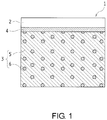
- Fig. 1 is a partially enlarged sectional view schematically illustrating a joining portion 4 and its periphery in a joining structure 1 according to the present embodiment.
- Fig. 1 is a sectional view, but hatching of a laser-transmitting resin member 2 is omitted so that the figure is easier to view.
- a size of each second resin component 6 is exaggeratively illustrated, but a real size of each second resin component 6 is on the level of several microns.
- this joining structure 1 is made up of a laser-transmitting resin member 2 formed of a thermoplastic resin and a laser-absorbing resin member 3 formed of a thermoplastic resin as well.
- the joining structure 1 is a structure in which, after the laser-transmitting resin member 2 and the laser-absorbing resin member 3 are installed to face each other and are pressurized to be brought into surface contact with each other, a laser beam is radiated from the laser-transmitting resin member 2 side, thereby melting and solidifying surface portions brought into surface contact with each other to join the two resin members 2 and 3.
- the laser-absorbing resin member 3 includes a first resin component 5 that is not compatible with the thermoplastic resin of which the laser-transmitting resin member 2 is formed, and second resin components 6 that are compatible with the thermoplastic resin of which the laser-transmitting resin member 2 is formed. In this way, even though the first resin component 5 that is not compatible with the laser-transmitting resin member 2 is included in the laser-absorbing resin member 3, the laser-transmitting resin member 2 and the laser-absorbing resin member 3 are firmly joined, which is one of the features of the joining structure 1 of the present time embodiment.
- “compatibility” refers to laser bondability.
- “Being compatible or having compatibility with” means that, for example when a laser beam is radiated to the laser-transmitting resin member 2 and the laser-absorbing resin member 3, which are brought into surface contact with each other, from the laser-transmitting resin member 2 side, the laser-absorbing resin member 3 absorbing the transmitted laser beam generates heat, and thereby the laser-transmitting resin member 2 and the laser-absorbing resin member 3 can be joined.
- thermoplastic resin of which the laser-transmitting resin member 2 is formed and a thermoplastic resin of which the first resin component 5 in the laser-absorbing resin member 3 is formed examples include polyvinyl chloride (PVC), polystyrene (PS), acrylonitrile styrene (AS), acrylonitrile butadiene styrene (ABS), polymethyl methacrylate (PMMA), polyethylene (PE), polypropylene (PP), polycarbonate (PC), modified polyphenylene ether (m-PPE), polyamide 6 (PA6), polyamide 66 (PA66), polyacetal (POM), polyethylene terephthalate (PET), polybutylene terephthalate (PBT), polysulfone (PSF), polyarylate (PAR), polyether imide (PEI), polyphenylene sulfide (PPS), polyether sulfone (PES), polyether ether ketone (PEEK), polyamide imide (PAI), a liquid crystal polyvin
- the laser-transmitting resin member 2 and the first resin component 5 may be a thermoplastic elastomer (TPE).
- TPE thermoplastic elastomer
- examples of the TPE include TPO (olefin series), TPS (styrene series), TPEE (ester series), TPU (urethane series), TPA (nylon series), and TPVC (vinyl chloride series).
- a filler may be added to the thermoplastic resin and the thermoplastic elastomer.
- the filler include an inorganic filler (a glass fiber, inorganic salt, etc.), a metallic filler, an organic filler, a carbon fiber, and the like.
- the laser-transmitting resin member 2 is required to transmit the laser beam, natural materials of the thermoplastic resin and the thermoplastic elastomer are preferably used.
- a dye that transmits the laser beam is preferably used rather than a pigment that absorbs and scatters the laser beam.
- the laser-absorbing resin member 3 is required to absorb the laser beam to generate heat, a resin component in which a laser absorption pigment called, for instance, carbon black is added to the thermoplastic resin and the thermoplastic elastomer is preferably used as the first resin component 5 in the laser-absorbing resin member 3.
- a resin component in which a laser absorption pigment called, for instance, carbon black is added to the thermoplastic resin and the thermoplastic elastomer is preferably used as the first resin component 5 in the laser-absorbing resin member 3.
- the second resin components 6 in the laser-absorbing resin member 3 for example a modified polymer, a block polymer, a graft polymer, etc., each of which has a polar group at a molecular terminal or in a side chain are preferred.
- the second resin components 6 include modified materials such as maleic anhydride, glycidyl methacrylate, oxazoline (modified epoxy), and modified imide, which use polypropylene (PP), polyethylene (PE), styrene ethylene propylene styrene copolymer (SEBS), polystyrene (PS), acrylonitrile styrene (AS), or acrylonitrile butadiene styrene copolymer (ABS) as a stem polymer.
- modified materials such as maleic anhydride, glycidyl methacrylate, oxazoline (modified epoxy), and modified imide, which use polypropylene (PP), polyethylene (PE), styrene ethylene propylene styrene copolymer (SEBS), polystyrene (PS), acrylonitrile styrene (AS), or acrylonitrile butadiene styrene copoly
- thermoplastic resin of which the laser-transmitting resin member 2 exemplified above is formed
- second resin components 6 that are compatible with the same
- specific examples are not enumerated in full.
- thermoplastic resin of which the laser-transmitting resin member 2 is formed is PMMA
- polyamide (PA) may be used as the first resin component 5
- maleic anhydride of ABS hereinafter referred to as acid-modified ABS
- the acid-modified ABS may be used as the second resin components 6.
- the acid-modified ABS is compatible with not only PMMA of which the laser-transmitting resin member 2 is formed but also PA or PBT that is the first resin component 5.
- the joining structure 1 of the present embodiment is formed by installing the laser-transmitting resin member 2 and the laser-absorbing resin member 3 to face each other, pressurizing the resin members to bring them into surface contact with each other, and then radiating the laser beam to the resin members from the laser-transmitting resin member 2 side.
- heat control is performed such that temperatures of a junction interface and its periphery of the laser-absorbing resin member 3 that absorbs the laser beam to generate heat are higher than or equal to a temperature at which the first resin component 5 and the second resin components 6 are melted together and remain flowable, and a temperature that is lower than or equal to a resin decomposition temperature.
- the joining portion 4 between the laser-transmitting resin member 2 and the laser-absorbing resin member 3 in the joining structure 1 is formed of a melted/solidified part at which junction interfaces and their peripheries of the laser-transmitting resin member 2 and the laser-absorbing resin member 3 are melted, and the melted laser-transmitting resin member 2 and the melted laser-absorbing resin member 3 are solidified in a mixed state.
- the laser-transmitting resin member 2 and the laser-absorbing resin member 3 are not simply mixed in the joining portion 4, and an abundance ratio of the second resin components 6 in the joining portion 4 is higher than that of the second resin components 6 in the laser-absorbing resin member 3 (a bulk).
- the joining structure 1 is configured such that the abundance ratio of the second resin components 6 in the joining portion 4 is more than or equal to 30 wt%. In this way, the second resin components 6 that are compatible with the laser-transmitting resin member 2 are adapted to be included in the joining portion 4 at a relatively large amount.
- the second resin components 6 when the junction interface and its periphery of the laser-absorbing resin member 3 is melted by suitable laser irradiation, the second resin components 6 that have small molecular weights and easy movement (high fluidity) seep out to the junction interface of the laser-absorbing resin member 3, and are abundantly collected on the joining portion 4, and thus the abundance ratio of the second resin components 6 in the joining portion 4 can be easily increased.
- the seepage of the second resin components 6 occurs only at the junction interface and its periphery that generate heat by absorbing the laser beam, and movement of the second resin components 6 does not occur at parts other than these in the laser-absorbing resin member 3.
- the joining structure 1 made up of the laser-transmitting resin member 2 and the laser-absorbing resin member 3 can be formed without changing characteristics of the laser-absorbing resin member 3 side.
- the abundance ratio of the second resin components 6 in the laser-absorbing resin member 3 is preferably more than or equal to 5 wt%, and more preferably 20 wt%.
- the present embodiment is different from the first embodiment in which a laser-absorbing resin member 13 is a polymer alloy having a sea-island structure.
- a laser-absorbing resin member 13 is a polymer alloy having a sea-island structure.
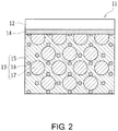
- Fig. 2 is a partially enlarged sectional view schematically illustrating a joining portion 14 and its periphery in a joining structure 11 according to the present embodiment.
- Fig. 2 is a sectional view, but hatching of a laser-transmitting resin member 12 is omitted so that the figure can be easily viewed.
- a size of each third resin component 17 that is an island component is exaggeratively illustrated, but a real size of each third resin component 17 is on the level of several microns.
- this joining structure 11 is made up of a laser-transmitting resin member 12 formed of a thermoplastic resin and a laser-absorbing resin member 13 that is also formed of a thermoplastic resin.
- the laser-absorbing resin member 13 is formed as a polymer alloy having a sea-island structure (a matrix domain structure) in which a first resin component 15 that is not compatible with the thermoplastic resin of which the laser-transmitting resin member 12 is formed is used as a sea component, and third resin components 17 that are compatible with the thermoplastic resin of which the laser-transmitting resin member 12 is formed are used as island components.
- a ratio between the first resin component 15 that is the sea component and the third resin components 17 that are the island components is, for instance, 3:7.
- Dispersion materials 16 are included in the laser-absorbing resin member 13 to produce a state in which the first resin component 15 and the third resin components 17 are mixed to form the sea-island structure.
- thermoplastic resin and a thermoplastic elastomer of which the laser-transmitting resin member 12 and the first and third resin components 15 and 17 are formed are identical to the thermoplastic resin or the thermoplastic elastomer of which the laser-transmitting resin member 2 and the first resin component 5 in the first embodiment are formed.
- natural materials of the thermoplastic resin and the thermoplastic elastomer are preferably used for the laser-transmitting resin member 12.
- resin components in which a laser absorption pigment called, for instance, carbon black is added to the thermoplastic resin and the thermoplastic elastomer are preferably used as the first and third resin components 15 and 17.
- the dispersion materials 16 used in the present embodiment include resin components that are compatible with the thermoplastic resin of which the laser-transmitting resin member 12 is formed, and resin components that are compatible with the first resin component 15.
- resin components for example a modified polymer, a block polymer, a graft polymer, etc., each of which has a polar group at a molecular terminal or in a side chain, are preferred.
- dispersion materials 16 include modified materials such as maleic anhydride, glycidyl methacrylate, oxazoline (modified epoxy), and modified imide, which use polypropylene (PP), polyethylene (PE), styrene ethylene propylene styrene copolymer (SEBS), polystyrene (PS), acrylonitrile styrene (AS), or acrylonitrile butadiene styrene copolymer (ABS) as a stem polymer.
- modified materials such as maleic anhydride, glycidyl methacrylate, oxazoline (modified epoxy), and modified imide, which use polypropylene (PP), polyethylene (PE), styrene ethylene propylene styrene copolymer (SEBS), polystyrene (PS), acrylonitrile styrene (AS), or acrylonitrile butadiene styrene copoly
- thermoplastic resin of which the laser-transmitting resin member 12 is formed is PMMA
- polyamide (PA) may be used as the first resin component
- ABS may be used as the third resin components 17
- maleic anhydride of ABS hereinafter referred to as acid-modified ABS
- thermoplastic resin of which the laser-transmitting resin member 12 is formed is PMMA
- the ABS may be used as the third resin components 17, and the acid-modified ABS may be used as the dispersion materials 16.
- the joining structure 11 of the present embodiment is formed by installing the laser-transmitting resin member 12 and the laser-absorbing resin member 13 to face each other, pressurizing the resin members to bring them into surface contact with each other, and then radiating a laser beam to the resin members from the laser-transmitting resin member 12 side.
- heat control is performed to be higher than or equal to a temperature at which the first and third resin components 15 and 17 and the dispersion materials 16 are melted together and remain flowable, and to be lower than or equal to a resin decomposition temperature.
- the dispersion materials 16 that have smaller molecular weights and easier movement (higher fluidity) than the first resin component 15 that is the sea component seep out to the junction interface of the laser-absorbing resin member 13, and are abundantly collected on a joining portion 14, and thus an abundance ratio of the dispersion materials 16 in the joining portion 14 can be easily increased.
- the joining structure 11 is configured such that the abundance ratio of the dispersion materials 16 in the joining portion 14 is more than or equal to 30 wt%.
- the dispersion materials 16 that are compatible with the laser-transmitting resin member 12 are included in the joining portion 14 at a relatively large amount.
- the laser-transmitting resin member 12 and the laser-absorbing resin member 13 can be firmly joined even though the first resin component 5 that is not compatible with the laser-transmitting resin member 12 is included in the laser-absorbing resin member 13.
- the third resin components 17 that are the island components are also compatible with the laser-transmitting resin member 12, it is thought that bonding strength between the laser-transmitting resin member 12 and the laser-absorbing resin member 13 can be increased even if the dispersion materials 16 are not present.
- the third resin components 17, the molecular weights of which are typically large in comparison with the dispersion materials 16 do not actively move to the junction interface, but remain in a bulk as the island components. Of course, this does not mean that the third resin components 17 do not contribute to the bonding strength.
- the laser irradiation is performed to a temperature at which the third resin components 17 are movable within a range that is lower than or equal to the resin decomposition temperature, and the bonding strength between the laser-transmitting resin member 12 and the laser-absorbing resin member 13 may be configured to be increased by a synergistic effect of the dispersion materials 16 and the third resin components 17.
- the seepage of the dispersion materials 16 occurs only at the junction interface and its periphery of the laser-absorbing resin member 13 that generate heat by absorbing the laser beam, and movement of the dispersion materials 16 does not occur at parts other than these in the laser-absorbing resin member 13.
- the joining structure 11 made up of the laser-transmitting resin member 12 and the laser-absorbing resin member 13 can be formed without changing characteristics of the polymer alloy having the sea-island structure.
- the abundance ratio of the dispersion materials 16 in the laser-absorbing resin member 13 is preferably more than or equal to 5 wt%, and more preferably 20 wt%.
- PA polyamide
- PBT polybutylene terephthalate
- the laser-absorbing resin members 23 containing PA included one that was formed of PA alone, two that were formed of PA and acid-modified ABS as the second resin component 6, and two that were formed of a polymer alloy having a sea-island structure in which PA was used as a sea component and acrylonitrile butadiene styrene copolymer (ABS) was used as an island component and of acid-modified ABS as the dispersion material 16.
- ABS acrylonitrile butadiene styrene copolymer
- resin members containing the acid-modified ABS of which the second resin components 6 or the dispersion materials 16 were formed resin members in which an abundance ratio of the acid-modified ABS was 20% were used.
- the laser-absorbing resin members 23 containing PBT included one that was formed of PBT alone, two that were formed of PBT and acid-modified ABS as the second resin component 6, and two that were formed of a polymer alloy having a sea-island structure in which PBT was used as a sea component and ABS was used as an island component and of acid-modified ABS as the dispersion material 16.
- resin members containing the acid-modified ABS of which the second resin components 6 or the dispersion materials 16 were formed resin members in which an abundance ratio of the acid-modified ABS was 20% were used.
- a laser beam 30 was radiated from the laser-transmitting resin member 22 side under the following first and second laser irradiation conditions, thereby melting and solidifying surface portions brought into surface contact with each other.
- Comparative Examples 1 and 3 using the samples 21 made under the second laser irradiation conditions in spite of containing the acid-modified ABS that was the second resin component 6, it was confirmed that the abundance ratio of the acid-modified ABS in the joining portion 24 was 20%. For this reason, in Comparative Examples 1 and 3 using the samples 21 made with relatively low laser output, it was confirmed that the abundance ratio of the acid-modified ABS in the joining portion 24 and the abundance ratio of the acid-modified ABS in the bulk were identical to each other, and that the laser-absorbing resin member 23 was joined with the laser-transmitting resin member 22 in situ.
- Comparative Examples 1 and 3 directly peeled off, but easily peeled off when subjected to free fall at a height of 1 m.
- Comparative Examples 2 and 4 using the samples 21 made under the second laser irradiation conditions, in spite of containing the ABS compatible with the PMMA in addition to the acid-modified ABS, it was confirmed that the abundance ratio of the acid-modified ABS in the joining portion 24 was 20%. For this reason, Comparative Examples 2 and 4 directly peeled off, but easily peeled off when subjected to free fall at a height of 1 m.
- the joining structures 1 and 11 of the present invention it is confirmed that, even when the components that are not compatible with the laser-transmitting resin members 2 and 12 are contained in the laser-absorbing resin members 3 and 13, the laser-transmitting resin members 2 and 12 and the laser-absorbing resin members 3 and 13 can be firmly joined.
- the acid-modified ABS is given as the second resin component 6 and the dispersion material 16 by way of example, but without being limited thereto, the second resin component 6 and the dispersion material 16 may be different resin components.
- the laser-transmitting resin member and the laser-absorbing resin member can be firmly joined.
- it is very useful in application to the joining structure made up of the laser-transmitting resin member and the laser-absorbing resin member.
Landscapes
- Physics & Mathematics (AREA)
- Engineering & Computer Science (AREA)
- Mechanical Engineering (AREA)
- Optics & Photonics (AREA)
- Health & Medical Sciences (AREA)
- Toxicology (AREA)
- Electromagnetism (AREA)
- Thermal Sciences (AREA)
- Ceramic Engineering (AREA)
- Lining Or Joining Of Plastics Or The Like (AREA)
- Laser Beam Processing (AREA)
- Laminated Bodies (AREA)
- Compositions Of Macromolecular Compounds (AREA)
Abstract
Description
- The present invention relates to a joining structure in which different types of resin members are joined, and particularly to a joining structure in which a laser-transmitting resin member and a laser-absorbing resin member are laser-joined.
- Conventionally, a joining structure in which different types of resin members are joined is known. When this joining structure is formed, the resin members are generally bonded via an adhesive or the like. However, in recent years, in consideration of recyclability, a reduction in man-hour, etc., different types of resin members have been frequently joined by laser bonding using a laser beam.
- However, since this joining structure is originally configured to join different members that are difficult to join, sufficient strength is not obtained in the method using the laser bonding when compatibility (laser bondability) of resins is low or when there is no compatibility. Thus, there is a problem that a combination of the resin members constituting the joining structure is naturally limited.
- To solve this problem, it is disclosed, for instance, in
Patent Literature 1 that at least one of a first resin molding formed of a first thermoplastic resin and a second resin molding formed of a second thermoplastic resin is made to contain a compatibilizing agent for the first and second thermoplastic resins, and the first resin molding and the second resin molding are joined by laser irradiation. According to the disclosure ofPatent Literature 1, since the thermoplastic resin composition of which at least one of the joined resin moldings is formed is made to contain the compatibilizing agent, the disclosure is configured to enable application to a wide combination of resins and to enable a great improvement in bonding strength. - Japanese Patent Application Laid-Open (
JP-A) No. 2006-312303 - According to the disclosure of
Patent Literature 1, since the first and second thermoplastic resins are made to contain the compatibilizing agent having compatibility, even when a component that is not compatible with the first thermoplastic resin is contained in the second resin molding, the first resin molding and the second resin molding can be joined by laser irradiation. - However, simply including the compatibilizing agent and performing the laser irradiation are merely depending on the compatibility of the first and second thermoplastic resins with the compatibilizing agent, in other words, a characteristic of the compatibilizing agent. Considering that the compatibility also varies, there is a problem that there is a lack of reliability in terms of the improvement of the bonding strength.
- To obtain sufficient bonding strength in the disclosure of
Patent Literature 1, the compatibilizing agent is limited to some extent. As a result, since the combination of the resins is naturally limited, it is hard to say that the disclosure can be applied to a wide range of combinations of resins. - The present invention was made in view of such circumstances, and an object thereof is to provide a technique in which, in a joining structure composed of a laser-transmitting resin member and a laser-absorbing resin member, even when a resin component that is not compatible with the laser-transmitting resin member is included in the laser-absorbing resin member, the resin members are firmly joined.
- To achieve the above object, a joining structure according to the present invention is configured to not only include a resin component that is compatible with a laser-transmitting resin member in a laser-absorbing resin member, but also to increase an abundance ratio of the resin component in a joining portion.
- To be specific, the present invention is a joining structure including a laser-transmitting resin member and a laser-absorbing resin member. The laser-absorbing resin member includes a first resin component, which is not compatible with the laser-transmitting resin member, and a second resin component, which is compatible with the laser-transmitting resin member. An abundance ratio of the second resin component in a melted/solidified part that constitutes the joining portion of the laser-transmitting resin member and the laser-absorbing resin member is higher than that of the second resin component in the laser-absorbing resin member.
- In the present invention, "laser-transmitting resin member" refers to a resin member that transmits an irradiated laser beam, and "laser-absorbing resin member" refers to a resin member that absorbs the irradiated laser beam to generate heat.
- In the present invention, "compatibility" refers to laser bondability. "Being compatible or having compatibility with" means that, for example, when a laser beam is radiated to the laser-transmitting resin member and the laser-absorbing resin member, which are brought into close contact with each other, from the side of the laser-transmitting resin member, the laser-absorbing resin member absorbing the transmitted laser beam generates heat, and thereby the laser-transmitting resin member and the laser-absorbing resin member can be joined (welded).
- According to the configuration, since the second resin component, which has the compatibility (the laser bondability) with the laser-transmitting resin member, is included in the laser-absorbing resin member, even when the resin component, which does not have the compatibility with the laser-transmitting resin member, is included in the laser-absorbing resin member, the laser-transmitting resin member and the laser-absorbing resin member can be joined.
- However, since the second resin component of the resin components included in the laser-absorbing resin member is present in the joining portion of the laser-transmitting resin member and the laser-absorbing resin member at a relatively large amount, the laser-transmitting resin member and the laser-absorbing resin member can be firmly joined. In addition, since the second resin component is present in the joining portion at a large amount, even when the compatibility between the laser-transmitting resin member and the second resin component is not relatively high, bonding strength between the laser-transmitting resin member and the laser-absorbing resin member can be reliably improved.
- In this way, in the present invention, without depending on only characteristics of the second resin component that is compatible with the laser-transmitting resin member, since the abundance ratio of the second resin component in the joining portion is increased to enhance the bonding strength, choice of the second resin component becomes wider, and the second resin component can be applied to a wide combination in association with this.
- Here, making the abundance ratio of the second resin component in the joining portion higher than that of the second resin component in the laser-absorbing resin member can be easily realized because the second resin component easily oozes out to a junction interface of the laser-absorbing resin member, for instance, by adjusting output of the laser beam or selecting a resin component having smaller molecular weight (higher fluidity) than the first resin component as the second resin component. However, when the abundance ratio of the second resin component in the laser-absorbing resin member is excessively low, an amount of ooze of the second resin component is reduced, and thus it may be difficult to improve the bonding strength between the laser-transmitting resin member and the laser-absorbing resin member.
- Therefore, in the joining structure, the abundance ratio of the second resin component in the laser-absorbing resin member is preferably more than or equal to 5 wt%.
- The idea that the resin component that is compatible with the laser-transmitting resin member is made to be present in the joining portion of the laser-transmitting resin member and the laser-absorbing resin member at a relatively large amount and thereby the bonding strength is improved can also be applied to a case in which the laser-absorbing resin member is a polymer alloy having a sea-island structure (a matrix domain structure).
- To be specific, the present invention is a joining structure including a laser-transmitting resin member and a laser-absorbing resin member. The laser-absorbing resin member is a polymer alloy that has a sea-island structure in which a first resin component, which is not compatible with the laser-transmitting resin member, is used as a sea component and a third resin component, which is compatible with the laser-transmitting resin member is used as an island component, and the polymer alloy includes a dispersion material that is compatible with the first resin component. An abundance ratio of the dispersion material in a melted/solidified part that constitutes the joining portion of the laser-transmitting resin member and the laser-absorbing resin member is higher than that of the dispersion material in the laser-absorbing resin member.
- According to this configuration, since the polymer alloy having the sea-island structure in which the first resin component is used as the sea component and the third resin component is used as an island component is used as the laser-absorbing resin member, a joining structure having advantages of the first resin component and the third resin component (supplementing disadvantages of the first resin component and the third resin component) can be realized.
- However, the dispersion material having smaller molecular weight and easier movement than the first and third resin components actively oozes out to the junction interface of the laser-absorbing resin member during joining (melting). Thereby, the abundance ratio of the dispersion material in the joining portion is increased, and thus laser-transmitting resin member and the laser-absorbing resin member can be more firmly joined.
- When the second resin component is also compatible with the first resin component, the second resin component can be used as the dispersion material. That is, the configuration (the latter invention) using the polymer alloy having the sea-island structure as the laser-absorbing resin member can be said to be an aspect of the case in which, in the configuration (the former invention) using a resin member including the first and second resin components as the laser-absorbing resin member, the second resin component is also compatible with the first resin component and the laser-absorbing resin member includes the third resin component.
- Thus, in this joining structure, for the same reason as the former invention, the abundance ratio of the dispersion material in the laser-absorbing resin member is preferably more than or equal to 5 wt%.
- As described above, according to the joining structure of the present invention, even when a resin component that is not compatible with a laser-transmitting resin member is included in a laser-absorbing resin member, the laser-transmitting resin member and the laser-absorbing resin member can be firmly joined.
-
-
Fig. 1 is a partially enlarged sectional view schematically illustrating a joining portion and its periphery in a joining structure according to a first embodiment of the present invention. -
Fig. 2 is a partially enlarged sectional view schematically illustrating a joining portion and its periphery in a joining structure according to a second embodiment of the present invention. -
Fig. 3 is a view schematically illustrating a sample making method used in an experimental example. - Hereinafter, embodiments for carrying out the present invention will be described on the basis of the drawings.
-
Fig. 1 is a partially enlarged sectional view schematically illustrating a joiningportion 4 and its periphery in ajoining structure 1 according to the present embodiment.Fig. 1 is a sectional view, but hatching of a laser-transmittingresin member 2 is omitted so that the figure is easier to view. InFig. 1 , a size of each second resin component 6 is exaggeratively illustrated, but a real size of each second resin component 6 is on the level of several microns. - As illustrated in
Fig. 1 , this joiningstructure 1 is made up of a laser-transmittingresin member 2 formed of a thermoplastic resin and a laser-absorbingresin member 3 formed of a thermoplastic resin as well. In greater detail, thejoining structure 1 is a structure in which, after the laser-transmittingresin member 2 and the laser-absorbingresin member 3 are installed to face each other and are pressurized to be brought into surface contact with each other, a laser beam is radiated from the laser-transmittingresin member 2 side, thereby melting and solidifying surface portions brought into surface contact with each other to join the tworesin members - The laser-absorbing
resin member 3 includes afirst resin component 5 that is not compatible with the thermoplastic resin of which the laser-transmittingresin member 2 is formed, and second resin components 6 that are compatible with the thermoplastic resin of which the laser-transmittingresin member 2 is formed. In this way, even though thefirst resin component 5 that is not compatible with the laser-transmittingresin member 2 is included in the laser-absorbingresin member 3, the laser-transmittingresin member 2 and the laser-absorbingresin member 3 are firmly joined, which is one of the features of the joiningstructure 1 of the present time embodiment. - In the present embodiment, "compatibility" refers to laser bondability. "Being compatible or having compatibility with" means that, for example when a laser beam is radiated to the laser-transmitting
resin member 2 and the laser-absorbingresin member 3, which are brought into surface contact with each other, from the laser-transmittingresin member 2 side, the laser-absorbingresin member 3 absorbing the transmitted laser beam generates heat, and thereby the laser-transmittingresin member 2 and the laser-absorbingresin member 3 can be joined. - Examples of the thermoplastic resin of which the laser-transmitting
resin member 2 is formed and a thermoplastic resin of which thefirst resin component 5 in the laser-absorbingresin member 3 is formed include polyvinyl chloride (PVC), polystyrene (PS), acrylonitrile styrene (AS), acrylonitrile butadiene styrene (ABS), polymethyl methacrylate (PMMA), polyethylene (PE), polypropylene (PP), polycarbonate (PC), modified polyphenylene ether (m-PPE), polyamide 6 (PA6), polyamide 66 (PA66), polyacetal (POM), polyethylene terephthalate (PET), polybutylene terephthalate (PBT), polysulfone (PSF), polyarylate (PAR), polyether imide (PEI), polyphenylene sulfide (PPS), polyether sulfone (PES), polyether ether ketone (PEEK), polyamide imide (PAI), a liquid crystal polymer (LCP), polyvinylidene chloride (PVDC), polytetrafluoroethylene (PTFE), polychlorotrifluoroethylene (PCTFE), and polyvinylidene fluoride (PVDF). The laser-transmittingresin member 2 and thefirst resin component 5 may be a thermoplastic elastomer (TPE). Examples of the TPE include TPO (olefin series), TPS (styrene series), TPEE (ester series), TPU (urethane series), TPA (nylon series), and TPVC (vinyl chloride series). - A filler may be added to the thermoplastic resin and the thermoplastic elastomer. Examples of the filler include an inorganic filler (a glass fiber, inorganic salt, etc.), a metallic filler, an organic filler, a carbon fiber, and the like.
- Thus, since the laser-transmitting
resin member 2 is required to transmit the laser beam, natural materials of the thermoplastic resin and the thermoplastic elastomer are preferably used. When the laser-transmittingresin member 2 is colored, a dye that transmits the laser beam is preferably used rather than a pigment that absorbs and scatters the laser beam. - Meanwhile, since the laser-absorbing
resin member 3 is required to absorb the laser beam to generate heat, a resin component in which a laser absorption pigment called, for instance, carbon black is added to the thermoplastic resin and the thermoplastic elastomer is preferably used as thefirst resin component 5 in the laser-absorbingresin member 3. - As the second resin components 6 in the laser-absorbing
resin member 3, for example a modified polymer, a block polymer, a graft polymer, etc., each of which has a polar group at a molecular terminal or in a side chain are preferred. Examples of the second resin components 6 include modified materials such as maleic anhydride, glycidyl methacrylate, oxazoline (modified epoxy), and modified imide, which use polypropylene (PP), polyethylene (PE), styrene ethylene propylene styrene copolymer (SEBS), polystyrene (PS), acrylonitrile styrene (AS), or acrylonitrile butadiene styrene copolymer (ABS) as a stem polymer. - Here, since combinations of the
first resin component 5 that is not compatible with the thermoplastic resin of which the laser-transmittingresin member 2 exemplified above is formed and the second resin components 6 that are compatible with the same are various, specific examples are not enumerated in full. Here, only two specific examples are shown. For example, when the thermoplastic resin of which the laser-transmittingresin member 2 is formed is PMMA, polyamide (PA) may be used as thefirst resin component 5, and maleic anhydride of ABS (hereinafter referred to as acid-modified ABS) may be used as the second resin components 6. In a case in which the thermoplastic resin of which the laser-transmittingresin member 2 is formed is PMMA, even when PBT is used as thefirst resin component 5, the acid-modified ABS may be used as the second resin components 6. The acid-modified ABS is compatible with not only PMMA of which the laser-transmittingresin member 2 is formed but also PA or PBT that is thefirst resin component 5. - As described above, the joining
structure 1 of the present embodiment is formed by installing the laser-transmittingresin member 2 and the laser-absorbingresin member 3 to face each other, pressurizing the resin members to bring them into surface contact with each other, and then radiating the laser beam to the resin members from the laser-transmittingresin member 2 side. In this laser irradiation, heat control is performed such that temperatures of a junction interface and its periphery of the laser-absorbingresin member 3 that absorbs the laser beam to generate heat are higher than or equal to a temperature at which thefirst resin component 5 and the second resin components 6 are melted together and remain flowable, and a temperature that is lower than or equal to a resin decomposition temperature. Therefore, the joiningportion 4 between the laser-transmittingresin member 2 and the laser-absorbingresin member 3 in the joiningstructure 1 is formed of a melted/solidified part at which junction interfaces and their peripheries of the laser-transmittingresin member 2 and the laser-absorbingresin member 3 are melted, and the melted laser-transmittingresin member 2 and the melted laser-absorbingresin member 3 are solidified in a mixed state. - Thus, in the joining
structure 1 of the present embodiment, the laser-transmittingresin member 2 and the laser-absorbingresin member 3 are not simply mixed in the joiningportion 4, and an abundance ratio of the second resin components 6 in the joiningportion 4 is higher than that of the second resin components 6 in the laser-absorbing resin member 3 (a bulk). To be specific, the joiningstructure 1 is configured such that the abundance ratio of the second resin components 6 in the joiningportion 4 is more than or equal to 30 wt%. In this way, the second resin components 6 that are compatible with the laser-transmittingresin member 2 are adapted to be included in the joiningportion 4 at a relatively large amount. Thereby, a diffusion phenomenon of the second resin components 6 occurs, and the laser-transmittingresin member 2 and the laser-absorbingresin member 3 can be firmly joined even though thefirst resin component 5 that is not compatible with the laser-transmittingresin member 2 is included in the laser-absorbingresin member 3. - Making the abundance ratio of the second resin components 6 in the joining
portion 4 higher than that of the second resin components 6 in the laser-absorbing resin member 3 (the bulk) can be easily realized, for instance, by adjusting output of the laser beam or selecting resin components having smaller molecular weights than thefirst resin component 5 as the second resin components 6. That is, if the resin components having smaller molecular weights than thefirst resin component 5 are selected as the second resin components 6, when the junction interface and its periphery of the laser-absorbingresin member 3 is melted by suitable laser irradiation, the second resin components 6 that have small molecular weights and easy movement (high fluidity) seep out to the junction interface of the laser-absorbingresin member 3, and are abundantly collected on the joiningportion 4, and thus the abundance ratio of the second resin components 6 in the joiningportion 4 can be easily increased. - The seepage of the second resin components 6 occurs only at the junction interface and its periphery that generate heat by absorbing the laser beam, and movement of the second resin components 6 does not occur at parts other than these in the laser-absorbing
resin member 3. Thereby, the joiningstructure 1 made up of the laser-transmittingresin member 2 and the laser-absorbingresin member 3 can be formed without changing characteristics of the laser-absorbingresin member 3 side. - When the abundance ratio of the second resin components 6 in the laser-absorbing
resin member 3 is excessively low, although the second resin components 6 can be collected on the joiningportion 4, an amount of seepage of the second resin components 6 is reduced. Thus, it may be difficult to improve the bonding strength between the laser-transmittingresin member 2 and the laser-absorbingresin member 3. For this reason, the abundance ratio of the second resin components 6 in the laser-absorbingresin member 3 is preferably more than or equal to 5 wt%, and more preferably 20 wt%. - The present embodiment is different from the first embodiment in which a laser-absorbing resin member 13 is a polymer alloy having a sea-island structure. Hereinafter, differences from the first embodiment will be mainly described.
-
Fig. 2 is a partially enlarged sectional view schematically illustrating a joiningportion 14 and its periphery in a joiningstructure 11 according to the present embodiment.Fig. 2 is a sectional view, but hatching of a laser-transmittingresin member 12 is omitted so that the figure can be easily viewed. InFig. 2 , a size of eachthird resin component 17 that is an island component is exaggeratively illustrated, but a real size of eachthird resin component 17 is on the level of several microns. - As illustrated in
Fig. 2 , this joiningstructure 11 is made up of a laser-transmittingresin member 12 formed of a thermoplastic resin and a laser-absorbing resin member 13 that is also formed of a thermoplastic resin. The laser-absorbing resin member 13 is formed as a polymer alloy having a sea-island structure (a matrix domain structure) in which afirst resin component 15 that is not compatible with the thermoplastic resin of which the laser-transmittingresin member 12 is formed is used as a sea component, andthird resin components 17 that are compatible with the thermoplastic resin of which the laser-transmittingresin member 12 is formed are used as island components. In the joiningstructure 11, a ratio between thefirst resin component 15 that is the sea component and thethird resin components 17 that are the island components is, for instance, 3:7. Dispersion materials 16 are included in the laser-absorbing resin member 13 to produce a state in which thefirst resin component 15 and thethird resin components 17 are mixed to form the sea-island structure. - The thermoplastic resin and a thermoplastic elastomer of which the laser-transmitting
resin member 12 and the first andthird resin components resin member 2 and thefirst resin component 5 in the first embodiment are formed. Thus, natural materials of the thermoplastic resin and the thermoplastic elastomer are preferably used for the laser-transmittingresin member 12. On the other hand, resin components in which a laser absorption pigment called, for instance, carbon black is added to the thermoplastic resin and the thermoplastic elastomer are preferably used as the first andthird resin components - The dispersion materials 16 used in the present embodiment include resin components that are compatible with the thermoplastic resin of which the laser-transmitting
resin member 12 is formed, and resin components that are compatible with thefirst resin component 15. As the dispersion materials, for example a modified polymer, a block polymer, a graft polymer, etc., each of which has a polar group at a molecular terminal or in a side chain, are preferred. Examples of the dispersion materials 16 include modified materials such as maleic anhydride, glycidyl methacrylate, oxazoline (modified epoxy), and modified imide, which use polypropylene (PP), polyethylene (PE), styrene ethylene propylene styrene copolymer (SEBS), polystyrene (PS), acrylonitrile styrene (AS), or acrylonitrile butadiene styrene copolymer (ABS) as a stem polymer. - Here, since combinations of the
first resin component 15 that is not compatible with the thermoplastic resin of which the laser-transmittingresin member 12 exemplified above is formed, thethird resin components 17 that are compatible with the same, and the dispersion materials 16 are various, specific examples are not enumerated in full. Here, only two specific examples are shown. For example, when the thermoplastic resin of which the laser-transmittingresin member 12 is formed is PMMA, polyamide (PA) may be used as thefirst resin component 15, ABS may be used as thethird resin components 17, and maleic anhydride of ABS (hereinafter referred to as acid-modified ABS) may be used as the dispersion materials 16. In a case in which the thermoplastic resin of which the laser-transmittingresin member 12 is formed is PMMA, even when PBT is used as thefirst resin component 15, the ABS may be used as thethird resin components 17, and the acid-modified ABS may be used as the dispersion materials 16. - The joining
structure 11 of the present embodiment is formed by installing the laser-transmittingresin member 12 and the laser-absorbing resin member 13 to face each other, pressurizing the resin members to bring them into surface contact with each other, and then radiating a laser beam to the resin members from the laser-transmittingresin member 12 side. In this laser irradiation, heat control is performed to be higher than or equal to a temperature at which the first andthird resin components - When a junction interface and its periphery of the laser-absorbing resin member 13 are melted by laser irradiation associated with this heat control, the dispersion materials 16 that have smaller molecular weights and easier movement (higher fluidity) than the
first resin component 15 that is the sea component seep out to the junction interface of the laser-absorbing resin member 13, and are abundantly collected on a joiningportion 14, and thus an abundance ratio of the dispersion materials 16 in the joiningportion 14 can be easily increased. To be specific, the joiningstructure 11 is configured such that the abundance ratio of the dispersion materials 16 in the joiningportion 14 is more than or equal to 30 wt%. In this way, the dispersion materials 16 that are compatible with the laser-transmittingresin member 12 are included in the joiningportion 14 at a relatively large amount. Thereby, the laser-transmittingresin member 12 and the laser-absorbing resin member 13 can be firmly joined even though thefirst resin component 5 that is not compatible with the laser-transmittingresin member 12 is included in the laser-absorbing resin member 13. - Here, since the
third resin components 17 that are the island components are also compatible with the laser-transmittingresin member 12, it is thought that bonding strength between the laser-transmittingresin member 12 and the laser-absorbing resin member 13 can be increased even if the dispersion materials 16 are not present. However, it has been confirmed from an experiment that thethird resin components 17, the molecular weights of which are typically large in comparison with the dispersion materials 16, do not actively move to the junction interface, but remain in a bulk as the island components. Of course, this does not mean that thethird resin components 17 do not contribute to the bonding strength. For example, the laser irradiation is performed to a temperature at which thethird resin components 17 are movable within a range that is lower than or equal to the resin decomposition temperature, and the bonding strength between the laser-transmittingresin member 12 and the laser-absorbing resin member 13 may be configured to be increased by a synergistic effect of the dispersion materials 16 and thethird resin components 17. - The seepage of the dispersion materials 16 occurs only at the junction interface and its periphery of the laser-absorbing resin member 13 that generate heat by absorbing the laser beam, and movement of the dispersion materials 16 does not occur at parts other than these in the laser-absorbing resin member 13. Thereby, the joining
structure 11 made up of the laser-transmittingresin member 12 and the laser-absorbing resin member 13 can be formed without changing characteristics of the polymer alloy having the sea-island structure. - When the abundance ratio of the dispersion materials 16 in the laser-absorbing resin member 13 is excessively low, although the dispersion materials 16 can be collected on the joining
portion 14, it is difficult to improve the bonding strength between the laser-transmittingresin member 12 and the laser-absorbing resin member 13 13 in some cases. For this reason, the abundance ratio of the dispersion materials 16 in the laser-absorbing resin member 13 is preferably more than or equal to 5 wt%, and more preferably 20 wt%. - Next, an experimental example performed to confirm bonding strength of the joining
structure Fig. 3 . - In an experimental example, it was examined whether or not bonding strength was improved by causing a resin component that is compatible with a laser-transmitting
resin member 22 to be included in a laser-absorbingresin member 23 and by causing an abundance ratio of the resin component in a joiningportion 24 between the laser-transmittingresin member 22 and the laser-absorbingresin member 23 to be higher than an abundance ratio in the laser-absorbing resin member 23 (the bulk). - To be specific, ten laser-transmitting
resin members 22, each of which was formed of a natural material of polymethyl methacrylate (PMMA) and had a plate shape that was 100 mm long, 17.5 mm wide, and 1 mm thick, were prepared. In addition, five laser-absorbingresin members 23, each of which contained polyamide (PA) to which carbon black was added and had a plate shape that was 100 mm long, 17.5 mm wide, and 2 mm thick, and five laser-absorbingresin members 23, each of which contained polybutylene terephthalate (PBT) to which carbon black was added and had a plate shape that was 100 mm long, 17.5 mm wide, and 2 mm thick, were prepared. - In detail, the laser-absorbing
resin members 23 containing PA included one that was formed of PA alone, two that were formed of PA and acid-modified ABS as the second resin component 6, and two that were formed of a polymer alloy having a sea-island structure in which PA was used as a sea component and acrylonitrile butadiene styrene copolymer (ABS) was used as an island component and of acid-modified ABS as the dispersion material 16. For the resin members containing the acid-modified ABS of which the second resin components 6 or the dispersion materials 16 were formed, resin members in which an abundance ratio of the acid-modified ABS was 20% were used. - In detail, the laser-absorbing
resin members 23 containing PBT included one that was formed of PBT alone, two that were formed of PBT and acid-modified ABS as the second resin component 6, and two that were formed of a polymer alloy having a sea-island structure in which PBT was used as a sea component and ABS was used as an island component and of acid-modified ABS as the dispersion material 16. For the resin members containing the acid-modified ABS of which the second resin components 6 or the dispersion materials 16 were formed, resin members in which an abundance ratio of the acid-modified ABS was 20% were used. - As illustrated in
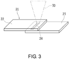
Fig. 3 , after the laser-transmittingresin member 22 and the laser-absorbingresin member 23 were installed to face each other and were pressurized to be brought into surface contact with each other, alaser beam 30 was radiated from the laser-transmittingresin member 22 side under the following first and second laser irradiation conditions, thereby melting and solidifying surface portions brought into surface contact with each other. Tensamples 21, in each of which both theresin members -
- Laser: Semiconductor laser (wavelength of 808 nm)
- Oscillation mode: Continuous oscillation
- Laser output: 5.8 W
- Focus diameter: 2 mm
- Close-contact pressure: 0.2 MPa
-
- Laser: Semiconductor laser (wavelength of 808 nm)
- Oscillation mode: Continuous oscillation
- Laser output: 4.0 W
- Focus diameter: 2 mm
- Close-contact pressure: 0.2 MPa
- Details of the ten
samples 21 obtained in this way are shown in Table 1. - As shown in Table 1, an experimental example using the
sample 21 in which the PA as thefirst resin component 5 and the acid-modified ABS as the second resin component 6 were contained in the laser-absorbingresin member 23 and which was made under the first laser irradiation conditions was used as Inventive Example 1. An experimental example using thesample 21 in which the PBT as thefirst resin component 5 and the acid-modified ABS as the second resin component 6 were contained in the laser-absorbingresin member 23 and which was made under the first laser irradiation conditions was used as Inventive Example 3. Inventive Examples 1 and 3 correspond to the joiningstructure 1 of the first embodiment. - In addition, an experimental example using the
sample 21 in which the PA as thefirst resin component 5, the ABS asthird resin component 17, and the acid-modified ABS as the dispersion material 16 were contained in the laser-absorbingresin member 23 and which was made under the first laser irradiation conditions was used as Inventive Example 2. An experimental example using thesample 21 in which the PBT as thefirst resin component 5, the ABS asthird resin component 17, and the acid-modified ABS as the dispersion material 16 were contained in the laser-absorbingresin member 23 and which was made under the first laser irradiation conditions was used as Inventive Example 4. Inventive Examples 2 and 4 correspond to the joiningstructure 11 of the second embodiment. - Meanwhile, experimental examples using the
samples 21 in which the same resin components as in Inventive Example 1, Inventive Example 2, Inventive Example 3, and Inventive Example 4 were contained in the laser-absorbingresin members 23 and which were made under the second laser irradiation conditions, in other words, with the laser output lower than those of Inventive Examples 1 to 4, were used as Comparative Example 1, Comparative Example 2, Comparative Example 3, and Comparative Example 4, respectively. As examples that did not contain the second resin component 6, an experimental example using thesample 21 in which the PA as thefirst resin component 5 was contained in the laser-absorbingresin member 23 and which was made under the first laser irradiation conditions was used as Comparative Example 5, and an experimental example using thesample 21 in which the PBT as thefirst resin component 5 was contained in the laser-absorbingresin member 23 and which was made under the first laser irradiation conditions was used as Comparative Example 6. - Junction evaluation was performed on Inventive Examples 1 to 4 and Comparative Examples 1 to 6, and the abundance ratio of the acid-modified ABS in the joining
portion 24 was measured for Inventive Examples 1 to 4 and Comparative Examples 1 to 4. - As the junction evaluation, an example that was hardly joined and directly peeled off was naturally determined to be "B" (Bad). An example that did not directly peel off but did peel off after being subjected to free fall at a height of 1 m was also determined to be "B" (Bad). Thus, only an example that did not peel off even after being subjected to free fall at a height of 1 m was determined to be "A" (Good). The measurement of the abundance ratio of the acid-modified ABS in the joining
portion 24 was performed using nano-IR that was an infrared spectroscopic analyzer having a nano-scale resolution. - First, it was confirmed from the table that the laser-transmitting
resin member 22 and the laser-absorbingresin member 23 were not joined in Comparative Examples 5 and 6 in which the PA that did not contain the second resin component 6, in other words, was not compatible with the PMMA, was merely combined with the PBT and the PMMA. - In Comparative Examples 1 and 3 using the
samples 21 made under the second laser irradiation conditions, in spite of containing the acid-modified ABS that was the second resin component 6, it was confirmed that the abundance ratio of the acid-modified ABS in the joiningportion 24 was 20%. For this reason, in Comparative Examples 1 and 3 using thesamples 21 made with relatively low laser output, it was confirmed that the abundance ratio of the acid-modified ABS in the joiningportion 24 and the abundance ratio of the acid-modified ABS in the bulk were identical to each other, and that the laser-absorbingresin member 23 was joined with the laser-transmittingresin member 22 in situ. That is, in Comparative Examples 1 and 3, the seepage of the acid-modified ABS did not occur, and the laser-transmittingresin member 22 and the laser-absorbingresin member 23 were only joined by the acid-modified ABS that was present in the junction interface. For this reason, Comparative Examples 1 and 3 directly peeled off, but easily peeled off when subjected to free fall at a height of 1 m. - Further, in Comparative Examples 2 and 4 using the
samples 21 made under the second laser irradiation conditions, in spite of containing the ABS compatible with the PMMA in addition to the acid-modified ABS, it was confirmed that the abundance ratio of the acid-modified ABS in the joiningportion 24 was 20%. For this reason, Comparative Examples 2 and 4 directly peeled off, but easily peeled off when subjected to free fall at a height of 1 m. - In contrast, in all of Inventive Examples 1 and 3 using the
samples 21 that contained the acid-modified ABS that was the second resin component 6 and were made under the first laser irradiation conditions, and Inventive Examples 2 and 4 using thesamples 21 that contained the ABS compatible with the PMMA in addition to the acid-modified ABS and were made under the first laser irradiation conditions, it was confirmed that the abundance ratio of the acid-modified ABS in the joiningportion 24 was 30 to 40%. For this reason, in Inventive Examples 1 to 4 having thesamples 21 made with relatively low laser output, it was confirmed that the acid-modified ABS that easily moves in a melted state seeped out to the junction interface of the laser-absorbingresin member 23, and positively contributed to the junction with the laser-transmittingresin member 22. For this reason, none of Inventive Examples 1 to 4 peeled off even after being subjected to the free fall at a height of 1 m. - As described above, according to the joining
structures resin members resin members 3 and 13, the laser-transmittingresin members resin members 3 and 13 can be firmly joined. - The present invention is not limited to the embodiments, and can be carried out in various other ways without departing from the spirit and the principal characteristic.
- In each of the above embodiments, the acid-modified ABS is given as the second resin component 6 and the dispersion material 16 by way of example, but without being limited thereto, the second resin component 6 and the dispersion material 16 may be different resin components.
- In this way, the aforementioned embodiments are merely simple examples in every respect, and should not be restrictively interpreted. Further, all alterations or modifications belonging to the equivalent scope of the claims are within the scope of the present invention. This application claims priority on Japanese Patent Application No.
2015-230442 - According to the present invention, even when the component that is not compatible with the laser-transmitting resin member is contained in the laser-absorbing resin member, the laser-transmitting resin member and the laser-absorbing resin member can be firmly joined. Thus, it is very useful in application to the joining structure made up of the laser-transmitting resin member and the laser-absorbing resin member.
-
- 1, 11 Joining structure
- 2, 12 Laser-transmitting resin member
- 3, 13 Laser-absorbing resin member
- 4, 14 Joining portion
- 5, 15 First resin component
- 6 Second resin component
- 16 Dispersion material
- 17 Third resin component
| Laser-transmitting resin member | Laser-absorbing resin member | Laser output (W) | Acid-modified ABS amount (wt%) | Junction evaluation | |||||
| Bulk | Joining portion | ||||||||
| Inventive Example | 1 | PMMA | PA | - | Acid-modified ABS | 5.8 | 20 | 30 to 40 | |
| 2 | PMMA | PA | ABS | Acid-modified ABS | 5.8 | 20 | 30 to 40 | |
|
| 3 | PMMA | PBT | - | Acid-modified ABS | 5.8 | 20 | 30 to 40 | |
|
| 4 | PMMA | PBT | ABS | Acid-modified ABS | 5.8 | 20 | 30 to 40 | A | |
| Comparative Example | 1 | PMMA | PA | - | Acid-modified ABS | 4.0 | 20 | 20 | |
| 2 | PMMA | PA | ABS | Acid-modified ABS | 4.0 | 20 | 20 | |
|
| 3 | PMMA | PBT | - | Acid-modified ABS | 4.0 | 20 | 20 | |
|
| 4 | PMMA | PBT | ABS | Acid-modified ABS | 4.0 | 20 | 20 | |
|
| 5 | PMMA | PA | - | - | 5.8 | 0 | 0 | B | |
| 6 | PMMA | PBT | - | - | 5.8 | 0 | 0 | B | |
Claims (4)
- A joining structure, comprises:
a laser-transmitting resin member and a laser-absorbing resin member, wherein:the laser-absorbing resin member comprises a first resin component, which is not compatible with the laser-transmitting resin member, and a second resin component, which is compatible with the laser-transmitting resin member; andan abundance ratio of the second resin component in a melted/solidified part that constitutes the joining portion of the laser-transmitting resin member and the laser-absorbing resin member is higher than that of the second resin component in the laser-absorbing resin member. - The joining structure according to claim 1, wherein the abundance ratio of the second resin component in the laser-absorbing resin member is more than or equal to 5 wt%.
- A joining structure, comprises:
a laser-transmitting resin member and a laser-absorbing resin member, wherein:the laser-absorbing resin member is a polymer alloy that has a sea-island structure in which a first resin component, which is not compatible with the laser-transmitting resin member, is used as a sea component and a third resin component, which is compatible with the laser-transmitting resin member, is used as an island component, and the polymer alloy comprises a dispersion material that is compatible with the first resin component; andan abundance ratio of the dispersion material in a melted/solidified part that constitutes the joining portion of the laser-transmitting resin member and the laser-absorbing resin member is higher than that of the dispersion material in the laser-absorbing resin member. - The joining structure according to claim 3, wherein the abundance ratio of the dispersion material in the laser-absorbing resin member is more than or equal to 5 wt%.
Applications Claiming Priority (2)
| Application Number | Priority Date | Filing Date | Title |
|---|---|---|---|
| JP2015230442A JP6500757B2 (en) | 2015-11-26 | 2015-11-26 | Bonding structure |
| PCT/JP2016/082522 WO2017090394A1 (en) | 2015-11-26 | 2016-11-02 | Joining structure |
Publications (3)
| Publication Number | Publication Date |
|---|---|
| EP3381682A1 true EP3381682A1 (en) | 2018-10-03 |
| EP3381682A4 EP3381682A4 (en) | 2019-07-10 |
| EP3381682B1 EP3381682B1 (en) | 2023-03-29 |
Family
ID=58763070
Family Applications (1)
| Application Number | Title | Priority Date | Filing Date |
|---|---|---|---|
| EP16868343.1A Active EP3381682B1 (en) | 2015-11-26 | 2016-11-02 | Joining structure |
Country Status (4)
| Country | Link |
|---|---|
| EP (1) | EP3381682B1 (en) |
| JP (1) | JP6500757B2 (en) |
| CN (1) | CN107848276B (en) |
| WO (1) | WO2017090394A1 (en) |
Families Citing this family (2)
| Publication number | Priority date | Publication date | Assignee | Title |
|---|---|---|---|---|
| JP7659882B2 (en) * | 2020-12-25 | 2025-04-10 | 地方独立行政法人東京都立産業技術研究センター | Manufacturing method of processed plastic material and processed plastic material |
| CN114351512B (en) * | 2021-12-17 | 2024-03-19 | 安徽森泰木塑集团股份有限公司 | A kind of biomass sleeper and preparation method thereof |
Family Cites Families (6)
| Publication number | Priority date | Publication date | Assignee | Title |
|---|---|---|---|---|
| JPH03143632A (en) * | 1989-10-31 | 1991-06-19 | Asahi Chem Ind Co Ltd | Laminated body and preparation thereof |
| FR2806348B1 (en) * | 2000-03-17 | 2002-11-15 | Rhodia Engineering Plastics Sa | ARTICLES COMPRISING A POLYOLEFIN-BASED ELEMENT ASSEMBLED TO A POLYAMIDE-BASED ELEMENT, AND METHOD FOR OBTAINING SAME |
| JP3610917B2 (en) * | 2001-03-27 | 2005-01-19 | トヨタ自動車株式会社 | Plastic molded product |
| JP2006312303A (en) * | 2004-10-01 | 2006-11-16 | Daicel Polymer Ltd | Laser beam welding resin composition and composite molding |
| CN1760272A (en) * | 2004-10-01 | 2006-04-19 | 大赛璐高分子株式会社 | Laser weldable resin composition and composite article |
| JP2008279730A (en) * | 2007-05-14 | 2008-11-20 | Denso Corp | Molded resin product and manufacturing method thereof |
-
2015
- 2015-11-26 JP JP2015230442A patent/JP6500757B2/en active Active
-
2016
- 2016-11-02 CN CN201680046498.2A patent/CN107848276B/en active Active
- 2016-11-02 EP EP16868343.1A patent/EP3381682B1/en active Active
- 2016-11-02 WO PCT/JP2016/082522 patent/WO2017090394A1/en not_active Ceased
Also Published As
| Publication number | Publication date |
|---|---|
| EP3381682B1 (en) | 2023-03-29 |
| CN107848276B (en) | 2019-07-16 |
| WO2017090394A1 (en) | 2017-06-01 |
| JP2017094630A (en) | 2017-06-01 |
| JP6500757B2 (en) | 2019-04-17 |
| EP3381682A4 (en) | 2019-07-10 |
| CN107848276A (en) | 2018-03-27 |
Similar Documents
| Publication | Publication Date | Title |
|---|---|---|
| Toledano et al. | Ions-modified nanoparticles affect functional remineralization and energy dissipation through the resin-dentin interface | |
| EP3381682B1 (en) | Joining structure | |
| US7785687B2 (en) | Molded resin product | |
| EP1941988A4 (en) | BODY WITH LASER | |
| US9403319B2 (en) | Reinforced thermoplastic structural joint assembly for a vehicle | |
| DE102004051457A1 (en) | Colored weldable plastics which are transparent, translucent or covered, contain nanoscale, laser-sensitive particles | |
| CN105473311B (en) | Joints and joining methods | |
| EP3676080A1 (en) | Liquid container and method for producing a liquid container | |
| US20070137779A1 (en) | Process for laser welding | |
| EP1524097A1 (en) | Resin mold and method for manufacturing the same | |
| Wissemborski et al. | Welding and Marking of plastics with lasers: new absorbers increase possibilities for application | |
| US8425706B2 (en) | Joint design for welding plastic assemblies | |
| KR20070089951A (en) | Laser weldable thermoplastic polymer composition and laser welding method | |
| US11458677B2 (en) | Selective laser sintering composition and selective laser sintering 3D printing method employing the same | |
| EP3683058B1 (en) | Screening method for preparing a laminate | |
| WO2007036577A1 (en) | Method of producing a plastic moulded part with an integrated window element by means of injection moulding and injection-moulded plastic moulded part with an integrated window element | |
| EP3712206A2 (en) | Bonding member for laser welding and laser welding method using same | |
| US11351704B2 (en) | Resin injection molding method | |
| EP2825366A1 (en) | Composite structural element and method | |
| AT511645A1 (en) | SANDWICH INJECTION MOLDING AND FORMING COMPRISING A LAYERED COMPOSITE PRODUCED BY THE SANDWICH MOLDING METHOD | |
| JP7404899B2 (en) | Composite molded body | |
| WO2017090393A1 (en) | Joining structure | |
| US20220153010A1 (en) | Single shear joint for node-to-node connections | |
| WO2007000163A8 (en) | Immobilisation of polypeptides by irradiation | |
| DE102018132016A1 (en) | Method for producing a three-dimensionally shaped automotive trim part |
Legal Events
| Date | Code | Title | Description |
|---|---|---|---|
| STAA | Information on the status of an ep patent application or granted ep patent |
Free format text: STATUS: THE INTERNATIONAL PUBLICATION HAS BEEN MADE |
|
| PUAI | Public reference made under article 153(3) epc to a published international application that has entered the european phase |
Free format text: ORIGINAL CODE: 0009012 |
|
| STAA | Information on the status of an ep patent application or granted ep patent |
Free format text: STATUS: REQUEST FOR EXAMINATION WAS MADE |
|
| 17P | Request for examination filed |
Effective date: 20180206 |
|
| AK | Designated contracting states |
Kind code of ref document: A1 Designated state(s): AL AT BE BG CH CY CZ DE DK EE ES FI FR GB GR HR HU IE IS IT LI LT LU LV MC MK MT NL NO PL PT RO RS SE SI SK SM TR |
|
| AX | Request for extension of the european patent |
Extension state: BA ME |
|
| DAV | Request for validation of the european patent (deleted) | ||
| DAX | Request for extension of the european patent (deleted) | ||
| REG | Reference to a national code |
Ref country code: DE Ref legal event code: R079 Ref document number: 602016078583 Country of ref document: DE Free format text: PREVIOUS MAIN CLASS: B32B0027000000 Ipc: B29C0065160000 |
|
| A4 | Supplementary search report drawn up and despatched |
Effective date: 20190606 |
|
| RIC1 | Information provided on ipc code assigned before grant |
Ipc: B29K 77/00 20060101ALN20190531BHEP Ipc: B32B 27/00 20060101ALN20190531BHEP Ipc: B32B 27/08 20060101ALN20190531BHEP Ipc: B29K 55/02 20060101ALN20190531BHEP Ipc: B29K 33/04 20060101ALN20190531BHEP Ipc: B32B 7/02 20190101ALN20190531BHEP Ipc: B29C 65/16 20060101AFI20190531BHEP Ipc: B29K 67/00 20060101ALN20190531BHEP |
|
| STAA | Information on the status of an ep patent application or granted ep patent |
Free format text: STATUS: EXAMINATION IS IN PROGRESS |
|
| 17Q | First examination report despatched |
Effective date: 20210628 |
|
| GRAP | Despatch of communication of intention to grant a patent |
Free format text: ORIGINAL CODE: EPIDOSNIGR1 |
|
| STAA | Information on the status of an ep patent application or granted ep patent |
Free format text: STATUS: GRANT OF PATENT IS INTENDED |
|
| INTG | Intention to grant announced |
Effective date: 20221102 |
|
| GRAS | Grant fee paid |
Free format text: ORIGINAL CODE: EPIDOSNIGR3 |
|
| GRAA | (expected) grant |
Free format text: ORIGINAL CODE: 0009210 |
|
| STAA | Information on the status of an ep patent application or granted ep patent |
Free format text: STATUS: THE PATENT HAS BEEN GRANTED |
|
| AK | Designated contracting states |
Kind code of ref document: B1 Designated state(s): AL AT BE BG CH CY CZ DE DK EE ES FI FR GB GR HR HU IE IS IT LI LT LU LV MC MK MT NL NO PL PT RO RS SE SI SK SM TR |
|
| REG | Reference to a national code |
Ref country code: GB Ref legal event code: FG4D |
|
| REG | Reference to a national code |
Ref country code: CH Ref legal event code: EP |
|
| REG | Reference to a national code |
Ref country code: DE Ref legal event code: R096 Ref document number: 602016078583 Country of ref document: DE |
|
| REG | Reference to a national code |
Ref country code: AT Ref legal event code: REF Ref document number: 1556395 Country of ref document: AT Kind code of ref document: T Effective date: 20230415 |
|
| REG | Reference to a national code |
Ref country code: IE Ref legal event code: FG4D |
|
| REG | Reference to a national code |
Ref country code: LT Ref legal event code: MG9D |
|
| PG25 | Lapsed in a contracting state [announced via postgrant information from national office to epo] |
Ref country code: RS Free format text: LAPSE BECAUSE OF FAILURE TO SUBMIT A TRANSLATION OF THE DESCRIPTION OR TO PAY THE FEE WITHIN THE PRESCRIBED TIME-LIMIT Effective date: 20230329 Ref country code: NO Free format text: LAPSE BECAUSE OF FAILURE TO SUBMIT A TRANSLATION OF THE DESCRIPTION OR TO PAY THE FEE WITHIN THE PRESCRIBED TIME-LIMIT Effective date: 20230629 Ref country code: LV Free format text: LAPSE BECAUSE OF FAILURE TO SUBMIT A TRANSLATION OF THE DESCRIPTION OR TO PAY THE FEE WITHIN THE PRESCRIBED TIME-LIMIT Effective date: 20230329 Ref country code: LT Free format text: LAPSE BECAUSE OF FAILURE TO SUBMIT A TRANSLATION OF THE DESCRIPTION OR TO PAY THE FEE WITHIN THE PRESCRIBED TIME-LIMIT Effective date: 20230329 Ref country code: HR Free format text: LAPSE BECAUSE OF FAILURE TO SUBMIT A TRANSLATION OF THE DESCRIPTION OR TO PAY THE FEE WITHIN THE PRESCRIBED TIME-LIMIT Effective date: 20230329 |
|
| REG | Reference to a national code |
Ref country code: NL Ref legal event code: MP Effective date: 20230329 |
|
| REG | Reference to a national code |
Ref country code: AT Ref legal event code: MK05 Ref document number: 1556395 Country of ref document: AT Kind code of ref document: T Effective date: 20230329 |
|
| PG25 | Lapsed in a contracting state [announced via postgrant information from national office to epo] |
Ref country code: SE Free format text: LAPSE BECAUSE OF FAILURE TO SUBMIT A TRANSLATION OF THE DESCRIPTION OR TO PAY THE FEE WITHIN THE PRESCRIBED TIME-LIMIT Effective date: 20230329 Ref country code: NL Free format text: LAPSE BECAUSE OF FAILURE TO SUBMIT A TRANSLATION OF THE DESCRIPTION OR TO PAY THE FEE WITHIN THE PRESCRIBED TIME-LIMIT Effective date: 20230329 Ref country code: GR Free format text: LAPSE BECAUSE OF FAILURE TO SUBMIT A TRANSLATION OF THE DESCRIPTION OR TO PAY THE FEE WITHIN THE PRESCRIBED TIME-LIMIT Effective date: 20230630 Ref country code: FI Free format text: LAPSE BECAUSE OF FAILURE TO SUBMIT A TRANSLATION OF THE DESCRIPTION OR TO PAY THE FEE WITHIN THE PRESCRIBED TIME-LIMIT Effective date: 20230329 |
|
| PG25 | Lapsed in a contracting state [announced via postgrant information from national office to epo] |
Ref country code: SM Free format text: LAPSE BECAUSE OF FAILURE TO SUBMIT A TRANSLATION OF THE DESCRIPTION OR TO PAY THE FEE WITHIN THE PRESCRIBED TIME-LIMIT Effective date: 20230329 Ref country code: RO Free format text: LAPSE BECAUSE OF FAILURE TO SUBMIT A TRANSLATION OF THE DESCRIPTION OR TO PAY THE FEE WITHIN THE PRESCRIBED TIME-LIMIT Effective date: 20230329 Ref country code: PT Free format text: LAPSE BECAUSE OF FAILURE TO SUBMIT A TRANSLATION OF THE DESCRIPTION OR TO PAY THE FEE WITHIN THE PRESCRIBED TIME-LIMIT Effective date: 20230731 Ref country code: ES Free format text: LAPSE BECAUSE OF FAILURE TO SUBMIT A TRANSLATION OF THE DESCRIPTION OR TO PAY THE FEE WITHIN THE PRESCRIBED TIME-LIMIT Effective date: 20230329 Ref country code: EE Free format text: LAPSE BECAUSE OF FAILURE TO SUBMIT A TRANSLATION OF THE DESCRIPTION OR TO PAY THE FEE WITHIN THE PRESCRIBED TIME-LIMIT Effective date: 20230329 Ref country code: AT Free format text: LAPSE BECAUSE OF FAILURE TO SUBMIT A TRANSLATION OF THE DESCRIPTION OR TO PAY THE FEE WITHIN THE PRESCRIBED TIME-LIMIT Effective date: 20230329 |
|
| PG25 | Lapsed in a contracting state [announced via postgrant information from national office to epo] |
Ref country code: SK Free format text: LAPSE BECAUSE OF FAILURE TO SUBMIT A TRANSLATION OF THE DESCRIPTION OR TO PAY THE FEE WITHIN THE PRESCRIBED TIME-LIMIT Effective date: 20230329 Ref country code: PL Free format text: LAPSE BECAUSE OF FAILURE TO SUBMIT A TRANSLATION OF THE DESCRIPTION OR TO PAY THE FEE WITHIN THE PRESCRIBED TIME-LIMIT Effective date: 20230329 Ref country code: IS Free format text: LAPSE BECAUSE OF FAILURE TO SUBMIT A TRANSLATION OF THE DESCRIPTION OR TO PAY THE FEE WITHIN THE PRESCRIBED TIME-LIMIT Effective date: 20230729 |
|
| REG | Reference to a national code |
Ref country code: DE Ref legal event code: R097 Ref document number: 602016078583 Country of ref document: DE |
|
| PG25 | Lapsed in a contracting state [announced via postgrant information from national office to epo] |
Ref country code: DK Free format text: LAPSE BECAUSE OF FAILURE TO SUBMIT A TRANSLATION OF THE DESCRIPTION OR TO PAY THE FEE WITHIN THE PRESCRIBED TIME-LIMIT Effective date: 20230329 Ref country code: CZ Free format text: LAPSE BECAUSE OF FAILURE TO SUBMIT A TRANSLATION OF THE DESCRIPTION OR TO PAY THE FEE WITHIN THE PRESCRIBED TIME-LIMIT Effective date: 20230329 |
|
| PLBE | No opposition filed within time limit |
Free format text: ORIGINAL CODE: 0009261 |
|
| STAA | Information on the status of an ep patent application or granted ep patent |
Free format text: STATUS: NO OPPOSITION FILED WITHIN TIME LIMIT |
|
| 26N | No opposition filed |
Effective date: 20240103 |
|
| PG25 | Lapsed in a contracting state [announced via postgrant information from national office to epo] |
Ref country code: SI Free format text: LAPSE BECAUSE OF FAILURE TO SUBMIT A TRANSLATION OF THE DESCRIPTION OR TO PAY THE FEE WITHIN THE PRESCRIBED TIME-LIMIT Effective date: 20230329 |
|
| PG25 | Lapsed in a contracting state [announced via postgrant information from national office to epo] |
Ref country code: SI Free format text: LAPSE BECAUSE OF FAILURE TO SUBMIT A TRANSLATION OF THE DESCRIPTION OR TO PAY THE FEE WITHIN THE PRESCRIBED TIME-LIMIT Effective date: 20230329 Ref country code: IT Free format text: LAPSE BECAUSE OF FAILURE TO SUBMIT A TRANSLATION OF THE DESCRIPTION OR TO PAY THE FEE WITHIN THE PRESCRIBED TIME-LIMIT Effective date: 20230329 |
|
| REG | Reference to a national code |
Ref country code: CH Ref legal event code: PL |
|
| PG25 | Lapsed in a contracting state [announced via postgrant information from national office to epo] |
Ref country code: MC Free format text: LAPSE BECAUSE OF FAILURE TO SUBMIT A TRANSLATION OF THE DESCRIPTION OR TO PAY THE FEE WITHIN THE PRESCRIBED TIME-LIMIT Effective date: 20230329 |
|
| PG25 | Lapsed in a contracting state [announced via postgrant information from national office to epo] |
Ref country code: LU Free format text: LAPSE BECAUSE OF NON-PAYMENT OF DUE FEES Effective date: 20231102 |
|
| PG25 | Lapsed in a contracting state [announced via postgrant information from national office to epo] |
Ref country code: CH Free format text: LAPSE BECAUSE OF NON-PAYMENT OF DUE FEES Effective date: 20231130 |
|
| GBPC | Gb: european patent ceased through non-payment of renewal fee |
Effective date: 20231102 |
|
| PG25 | Lapsed in a contracting state [announced via postgrant information from national office to epo] |
Ref country code: MC Free format text: LAPSE BECAUSE OF FAILURE TO SUBMIT A TRANSLATION OF THE DESCRIPTION OR TO PAY THE FEE WITHIN THE PRESCRIBED TIME-LIMIT Effective date: 20230329 Ref country code: LU Free format text: LAPSE BECAUSE OF NON-PAYMENT OF DUE FEES Effective date: 20231102 Ref country code: CH Free format text: LAPSE BECAUSE OF NON-PAYMENT OF DUE FEES Effective date: 20231130 |
|
| REG | Reference to a national code |
Ref country code: BE Ref legal event code: MM Effective date: 20231130 |
|
| REG | Reference to a national code |
Ref country code: IE Ref legal event code: MM4A |
|
| PG25 | Lapsed in a contracting state [announced via postgrant information from national office to epo] |
Ref country code: IE Free format text: LAPSE BECAUSE OF NON-PAYMENT OF DUE FEES Effective date: 20231102 |
|
| PG25 | Lapsed in a contracting state [announced via postgrant information from national office to epo] |
Ref country code: GB Free format text: LAPSE BECAUSE OF NON-PAYMENT OF DUE FEES Effective date: 20231102 |
|
| PG25 | Lapsed in a contracting state [announced via postgrant information from national office to epo] |
Ref country code: BE Free format text: LAPSE BECAUSE OF NON-PAYMENT OF DUE FEES Effective date: 20231130 |
|
| PG25 | Lapsed in a contracting state [announced via postgrant information from national office to epo] |
Ref country code: FR Free format text: LAPSE BECAUSE OF NON-PAYMENT OF DUE FEES Effective date: 20231130 |
|
| PG25 | Lapsed in a contracting state [announced via postgrant information from national office to epo] |
Ref country code: IE Free format text: LAPSE BECAUSE OF NON-PAYMENT OF DUE FEES Effective date: 20231102 Ref country code: GB Free format text: LAPSE BECAUSE OF NON-PAYMENT OF DUE FEES Effective date: 20231102 Ref country code: FR Free format text: LAPSE BECAUSE OF NON-PAYMENT OF DUE FEES Effective date: 20231130 Ref country code: BE Free format text: LAPSE BECAUSE OF NON-PAYMENT OF DUE FEES Effective date: 20231130 |
|
| PG25 | Lapsed in a contracting state [announced via postgrant information from national office to epo] |
Ref country code: BG Free format text: LAPSE BECAUSE OF FAILURE TO SUBMIT A TRANSLATION OF THE DESCRIPTION OR TO PAY THE FEE WITHIN THE PRESCRIBED TIME-LIMIT Effective date: 20230329 |
|
| PG25 | Lapsed in a contracting state [announced via postgrant information from national office to epo] |
Ref country code: BG Free format text: LAPSE BECAUSE OF FAILURE TO SUBMIT A TRANSLATION OF THE DESCRIPTION OR TO PAY THE FEE WITHIN THE PRESCRIBED TIME-LIMIT Effective date: 20230329 |
|
| PG25 | Lapsed in a contracting state [announced via postgrant information from national office to epo] |
Ref country code: CY Free format text: LAPSE BECAUSE OF FAILURE TO SUBMIT A TRANSLATION OF THE DESCRIPTION OR TO PAY THE FEE WITHIN THE PRESCRIBED TIME-LIMIT; INVALID AB INITIO Effective date: 20161102 |
|
| PG25 | Lapsed in a contracting state [announced via postgrant information from national office to epo] |
Ref country code: HU Free format text: LAPSE BECAUSE OF FAILURE TO SUBMIT A TRANSLATION OF THE DESCRIPTION OR TO PAY THE FEE WITHIN THE PRESCRIBED TIME-LIMIT; INVALID AB INITIO Effective date: 20161102 |
|
| PG25 | Lapsed in a contracting state [announced via postgrant information from national office to epo] |
Ref country code: TR Free format text: LAPSE BECAUSE OF FAILURE TO SUBMIT A TRANSLATION OF THE DESCRIPTION OR TO PAY THE FEE WITHIN THE PRESCRIBED TIME-LIMIT Effective date: 20230329 |
|
| PGFP | Annual fee paid to national office [announced via postgrant information from national office to epo] |
Ref country code: DE Payment date: 20251118 Year of fee payment: 10 |