EP3381647A1 - Injection molding machine and injection molding information processing device - Google Patents
Injection molding machine and injection molding information processing device Download PDFInfo
- Publication number
- EP3381647A1 EP3381647A1 EP18165179.5A EP18165179A EP3381647A1 EP 3381647 A1 EP3381647 A1 EP 3381647A1 EP 18165179 A EP18165179 A EP 18165179A EP 3381647 A1 EP3381647 A1 EP 3381647A1
- Authority
- EP
- European Patent Office
- Prior art keywords
- unit
- mold
- injection molding
- actual value
- molding machine
- Prior art date
- Legal status (The legal status is an assumption and is not a legal conclusion. Google has not performed a legal analysis and makes no representation as to the accuracy of the status listed.)
- Granted
Links
Images




Classifications
-
- B—PERFORMING OPERATIONS; TRANSPORTING
- B29—WORKING OF PLASTICS; WORKING OF SUBSTANCES IN A PLASTIC STATE IN GENERAL
- B29C—SHAPING OR JOINING OF PLASTICS; SHAPING OF MATERIAL IN A PLASTIC STATE, NOT OTHERWISE PROVIDED FOR; AFTER-TREATMENT OF THE SHAPED PRODUCTS, e.g. REPAIRING
- B29C45/00—Injection moulding, i.e. forcing the required volume of moulding material through a nozzle into a closed mould; Apparatus therefor
- B29C45/17—Component parts, details or accessories; Auxiliary operations
- B29C45/76—Measuring, controlling or regulating
- B29C45/768—Detecting defective moulding conditions
-
- B—PERFORMING OPERATIONS; TRANSPORTING
- B29—WORKING OF PLASTICS; WORKING OF SUBSTANCES IN A PLASTIC STATE IN GENERAL
- B29C—SHAPING OR JOINING OF PLASTICS; SHAPING OF MATERIAL IN A PLASTIC STATE, NOT OTHERWISE PROVIDED FOR; AFTER-TREATMENT OF THE SHAPED PRODUCTS, e.g. REPAIRING
- B29C2945/00—Indexing scheme relating to injection moulding, i.e. forcing the required volume of moulding material through a nozzle into a closed mould
- B29C2945/76—Measuring, controlling or regulating
- B29C2945/76494—Controlled parameter
- B29C2945/76498—Pressure
-
- B—PERFORMING OPERATIONS; TRANSPORTING
- B29—WORKING OF PLASTICS; WORKING OF SUBSTANCES IN A PLASTIC STATE IN GENERAL
- B29C—SHAPING OR JOINING OF PLASTICS; SHAPING OF MATERIAL IN A PLASTIC STATE, NOT OTHERWISE PROVIDED FOR; AFTER-TREATMENT OF THE SHAPED PRODUCTS, e.g. REPAIRING
- B29C2945/00—Indexing scheme relating to injection moulding, i.e. forcing the required volume of moulding material through a nozzle into a closed mould
- B29C2945/76—Measuring, controlling or regulating
- B29C2945/76494—Controlled parameter
- B29C2945/76531—Temperature
-
- B—PERFORMING OPERATIONS; TRANSPORTING
- B29—WORKING OF PLASTICS; WORKING OF SUBSTANCES IN A PLASTIC STATE IN GENERAL
- B29C—SHAPING OR JOINING OF PLASTICS; SHAPING OF MATERIAL IN A PLASTIC STATE, NOT OTHERWISE PROVIDED FOR; AFTER-TREATMENT OF THE SHAPED PRODUCTS, e.g. REPAIRING
- B29C2945/00—Indexing scheme relating to injection moulding, i.e. forcing the required volume of moulding material through a nozzle into a closed mould
- B29C2945/76—Measuring, controlling or regulating
- B29C2945/76494—Controlled parameter
- B29C2945/76551—Time
- B29C2945/76561—Time duration
-
- B—PERFORMING OPERATIONS; TRANSPORTING
- B29—WORKING OF PLASTICS; WORKING OF SUBSTANCES IN A PLASTIC STATE IN GENERAL
- B29C—SHAPING OR JOINING OF PLASTICS; SHAPING OF MATERIAL IN A PLASTIC STATE, NOT OTHERWISE PROVIDED FOR; AFTER-TREATMENT OF THE SHAPED PRODUCTS, e.g. REPAIRING
- B29C2945/00—Indexing scheme relating to injection moulding, i.e. forcing the required volume of moulding material through a nozzle into a closed mould
- B29C2945/76—Measuring, controlling or regulating
- B29C2945/76655—Location of control
- B29C2945/76732—Mould
Definitions
- Certain embodiment of the present invention relates to an injection molding machine and an injection molding information processing device.
- a quality management device described in Japanese Unexamined Patent Application Publication No. 64-14015 sets each molding condition in each molding process and an upper limit monitoring condition and a lower limit monitoring condition of some conditions or all conditions corresponding to each molding process and compares monitoring condition data and a detection value from each detector to predict abnormality.
- the present invention is made in consideration of the above-described problem, and an object thereof is to provide an injection molding machine capable of determining presence of absence of abnormality by comparing actual values of a physical amount relating to a manipulated variable with each other.
- an injection molding machine including: an injection molding information processing device which processes information relating to injection molding, in which the injection molding information processing device includes an actual value storage unit which, for each mold unit attached to the injection molding machine, stores molding information in which a set amount of a controlled variable which is molding conditions and an actual value of a physical amount relating to a manipulated variable for operating such that the controlled variable is the set value are associated with each other, and an actual value extraction unit which extracts the actual values of a plurality of shots performed under at least one of the same molding conditions and similar molding conditions, from the molding information stored in the actual value storage unit.
- an injection molding machine capable of determining presence of absence of abnormality by comparing actual values of the physical amount relating to the manipulated variable with each other is provided.
- Fig. 1 is a view showing a state when a mold opening of an injection molding machine according to an embodiment is completed.
- Fig. 2 is a view showing a state when a mold of the injection molding machine according to the embodiment is clamped.
- the injection molding machines include a mold clamping unit 100, an ejector unit 200, an injection unit 300, a movement unit 400, and a controller 700.
- a mold clamping unit 100 As shown in Figs. 1 and 2 , the injection molding machines include a mold clamping unit 100, an ejector unit 200, an injection unit 300, a movement unit 400, and a controller 700.
- a movement direction (right direction in Figs. 1 and 2 ) of a movable platen 120 when a mold is closed is defined as a front side
- a movement direction (left direction in Figs. 1 and 2 ) of the movable platen 120 when the mold is open is defined as a rear side.
- the mold clamping unit 100 performs closing, clamping, and opening on a mold unit 10.
- the mold clamping unit 100 is a horizontal type clamping unit and moldopening and closing directions are a horizontal direction.
- the mold clamping unit 100 includes a stationary platen 110, the movable platen 120, a toggle support 130, a tie bar 140, a toggle mechanism 150, a mold clamping motor 160, a motion conversion mechanism 170, and a mold space adjustment mechanism 180.
- the stationary platen 110 is fixed to the frame Fr.
- a stationary mold 11 is attached to a surface of the stationary platen 110 facing the movable platen 120.
- the movable platen 120 is movable in the mold opening and closing directions with respect to the frame Fr.
- a guide 101 which guides the movable platen 120 is placed on the frame Fr.
- a movable mold 12 is attached to a surface of the movable platen 120 facing the stationary platen 110.
- the movable platen 120 is moved forward or rearward with respect to the stationary platen 110, and thus, closing, clamping, and opening of the mold are performed.
- the mold unit 10 is configured of the stationary mold 11 and the movable mold 12.
- the toggle support 130 is connected to the stationary platen 110 with a gap therebetween, and is placed on the frame Fr to be movable in mold opening and closing directions .
- the toggle support 130 may be movable along a guide which is placed on the frame Fr.
- the guide of the toggle support 130 may be also used as the guide 101 of the movable platen 120.
- the stationary platen 110 is fixed to the frame Fr, and the toggle support 130 is movable in the mold opening and closing directions with respect to the frame Fr.
- the toggle support 130 may be fixed to the frame Fr, and the stationary platen 110 may be movable in the mold opening and closing directions with respect to the frame Fr.
- the stationary platen 110 and the toggle support 130 are connected to each other with a gap L in the mold opening and closing directions by the tie bar 140.
- Aplurality of (for example, four) tie bars 140 may be used.
- the tie bars 140 are parallel in the mold opening and closing directions and extend according to a mold clamping force.
- a tie bar strain detector 141 which detects strain of the tie bar 140 may be provided in at least one tie bar 140.
- the tie bar strain detector 141 sends signals indicating the detection results to the controller 700.
- the detection results of the tie bar strain detector 141 are used for detection or the like of the mold clamping force.
- the tie bar strain detector 141 is used as a mold clamping force detector which detects the mold clamping force.
- the mold clamping force detector is not limited to a strain gauge type detector, and may be a piezoelectric type detector, a capacitance type detector, a hydraulic type detector, an electromagnetic type detector, or the like, and the attachment position of the mold clamping force detector is also not limited to the tie bar 140.
- the toggle mechanism 150 is disposed between the movable platen 120 and the toggle support 130 and moves the movable platen 120 in the mold opening and closing directions with respect to the toggle support 130.
- the toggle mechanism 150 is configured of a crosshead 151, a pair of link groups, or the like.
- Each link group includes a first link 152 and a second link 153 which are bendably/strechably connected to each other by pins or the like.
- the first link 152 is attached to the movable platen 120 so as to be oscillated by pins or the like and the second link 153 is attached to the toggle support 130 so as to be oscillated by pins or the like.
- the second link 153 is attached to the crosshead 151 via a third link 154. If the crosshead 151 is moved forward or rearward with respect to the toggle support 130, the first link 152 and the second link 153 are bent and stretched and the movable platen 120 is moved forward or rearward with respect to the toggle support 130.
- the configuration of the toggle mechanism 150 is not limited to the configuration shown in Figs. 1 and 2 .
- the number of nodes of each link group is five.
- the number of nodes may be four, and one end portion of the third link 154 may be connected to a node between the first link 152 and the second link 153.
- the mold clamping motor 160 is attached to the toggle support 130 and operates the toggle mechanism 150.
- the mold clamping motor 160 moves the crosshead 151 forward or rearward with respect to the toggle support 130, and thus, the first links 152 and the second links 153 are bent and stretched, and the movable platen 120 is moved forward or rearward with respect to the toggle support 130.
- the mold clamping motor 160 is directly connected to the motion conversion mechanism 170.
- the mold clamping motor 160 may be connected to the motion conversion mechanism 170 via a belt, a pulley, or the like.
- the motion conversion mechanism 170 converts a rotary motion of the mold clamping motor 160 into a linear motion of the crosshead 151.
- the motion conversion mechanism 170 includes a screw shaft 171 and a screw nut 172 which is screwed to the screw shaft 171.
- a ball or a roller may be interposed between the screw shaft 171 and the screw nut 172.
- the mold clamping unit 100 performs a mold closing process, a mold clamping process, a mold opening process, or the like under the control of the controller 700.
- the mold clamping motor 160 is driven to move the crosshead 151 forward to a mold closing completion position at a set speed. Accordingly, the movable platen 120 is moved forward and the movable mold 12 comes into contact with the stationary mold 11. For example, a position or speed of the crosshead 151 is detected using a mold clamping motor encoder 161 or the like.
- the mold clamping motor encoder 161 detects the rotation of the mold clamping motor 160 and sends signals indicating the detection results to the controller 700.
- the mold clamping motor 160 is further driven to further move the crosshead 151 forward from the mold closing completion position to a mold clamping position, and thus, a mold clamping force is generated.
- a cavity space 14 is formed between the movable mold 12 and the stationary mold 11, and the cavity space 14 is filled with a liquid molding material by the injection unit 300.
- a filled molding material is solidified, and thus, a molding product is obtained.
- a plurality of cavity spaces 14 may be provided, and in this case, a plurality of molding products maybe simultaneously obtained.
- the mold clamping motor 160 is driven to move the crosshead 151 rearward to a mold opening completion position at a set speed. Accordingly, the movable platen 120 is moved rearward, and the movable mold 12 is separated from the stationary mold 11. Thereafter, the ejector unit 200 ejects the molding product from the movable mold 12.
- Setting conditions in the mold closing process and the mold clamping process are collectively set as a series of setting conditions.
- a speed or positions (including a speed switching position, a mold closing completion position, and a mold clamping position) of the crosshead 151 in the mold closing process and the mold clamping process are collectively set as a series of setting conditions .
- a speed, positions, or the like of the movable platen 120 maybe set.
- the mold clamping force may be set.
- the toggle mechanism 150 amplifies a driving force of the mold clamping motor 160 and transmits the driving force to the movable platen 120.
- An amplification magnification of the toggle mechanism 150 is also referred to as a toggle magnification.
- the toggle magnification is changed according to an angle ⁇ (hereinafter, also referred to a "link angle ⁇ ") between the first link 152 and the second link 153.
- the link angle ⁇ is obtained from the position of the crosshead 151.
- the toggle magnification becomes the maximum value.
- a mold space adjustment is performed such that a predetermined mold clamping force is obtained when the mold is clamped.
- the gap L between the stationary platen 110 and the toggle support 130 is adjusted such that the link angle ⁇ of the toggle mechanism 150 becomes a predetermined angle at the time of a mold touch where the movable mold 12 comes into contact with the stationary mold 11.
- the mold clamping unit 100 includes the mold space adjustment mechanism 180 which performs the mold space adjustment by adjusting the gap L between the stationary platen 110 and the toggle support 130.
- the mold space adjustment mechanism 180 includes a screw shaft 181 which is formed on a rear end portion of the tie bar 140, a screw nut 182 which is rotatably supported by the toggle support 130, and a mold space adjustment motor 183 which rotates the screw nut 182 screwed to the screw shaft 181.
- the screw shaft 181 and the screw nut 182 are provided for each tie bar 140.
- a rotation of the mold space adjustment motor 183 may be transmitted to a plurality of screw nuts 182 via a rotation transmission portion 185.
- the plurality of screw nuts 182 can be synchronously rotated.
- the rotation transmission portion 185 is configured of a gear or the like.
- a driven gear is formed on an outer periphery of each screw nut 182
- a drive gear is attached to an output shaft of the mold space adjustment motor 183
- an intermediate gear which engages with a plurality of driven gears and drive gears is rotatably held by a center portion of the toggle support 130.
- the rotation transmission portion 185 may be configured of a belt, a pulley, or the like instead of the gear.
- the controller 700 drives the mold space adjustment motor 183 to rotate the screw nut 182, and thus, the position of the toggle support 130 which rotatably holds the screw nut 182 with respect to the stationary platen 110 is adjusted, and the gap L between the stationary platen 110 and the toggle support 130 is adjusted.
- the screw nut 182 is rotatably held with respect to the toggle support 130 and the tie bar 140 in which the screw shaft 181 is formed is fixed to the stationary platen 110.
- the present invention is not limited to this.
- the screw nut 182 may be rotatably held with respect to the stationary platen 110 and the tie bar 140 may be fixed to the toggle support 130.
- the gap L can be adjusted by rotating the screw nut 182.
- the screw nut 182 maybe fixed to the toggle support 130 and the tie bar 140 may be rotatably held with respect to the stationary platen 110.
- the gap L can be adjusted by rotating the tie bar 140.
- the screw nut 182 may be fixed to the stationary platen 110 and the tie bar 140 may be rotatably held with respect to the toggle support 130. In this case, the gap L can be adjusted by rotating the tie bar 140.
- the gap L is detected using a mold space adjustment motor encoder 184.
- the mold space adjustment motor encoder 184 detects a rotation amount or a rotation direction of the mold space adjustment motor 183 and sends signals indicating the detection results to the controller 700.
- the detection results of the mold space adjustment motor encoder 184 are used to monitor or control the position of the toggle support 130 or the gap L.
- the mold space adjustment mechanism 180 rotates one of the screw shaft 181 and the screw nut 182 which are screwed to each other to adjust the gap L.
- a plurality of mold space adjustment mechanisms 180 maybe used, and a plurality of mold space adjustment motors 183 may be used.
- the mold space adjustment mechanism 180 of the present embodiment includes the screw shaft 181 formed on the tie bar 140 and the screw nut 182 screwed to the screw shaft 181.
- the present invention is not limited to this.
- the mold space adjustment mechanism 180 may include a tie bar temperature controller which controls the temperature of the tie bar 140.
- the tie bar temperature controller is attached to each tie bar 140 and coordinates the temperatures of the plurality of tie bars 140.
- the tie bar 140 is lengthened by heat expansion and the gap L increases as the temperature of the tie bar 140 increases.
- the temperatures of the plurality of tie bars 140 can be adjusted independently.
- the tie bar temperature controller includes a heating unit such as a heater and controls the temperature of the tie bar 140 by heating.
- the tie bar temperature controller may include a cooler such as a water cooling jacket and may control the temperature of the tie bar 140 by cooling.
- the tie bar temperature controller may include both the heating unit and the cooler.
- the mold clamping unit 100 of the present embodiment is a horizontal type mold clamping unit in which the mold opening and closing directions are horizontal directions.
- the mold clamping unit 100 may be a vertical type mold clamping unit in which the mold opening and closing directions are vertical directions.
- the vertical type mold clamping unit includes a lower platen, an upper platen, a toggle support, tie bars, a toggle mechanism, a mold clamping motor, or the like. Any one of the lower platen and the upper platen is used as a stationary platen and the other is used as a movable platen.
- a lower mold is attached to the lower platen and an upper mold is attached to the upper platen. The lower mold and the upper mold configure the mold unit.
- the lower mold may be attached to the lower platen via a rotary table.
- the toggle support is disposed below the lower platen and is connected to the upper platen via the tie bar.
- the upper platen and the toggle support are connected to each other in mold opening and closing directions by the tie bar with a gap therebetween.
- the toggle mechanism is disposed between the toggle support and the lower platen and lifts or lowers the movable platen.
- the mold clamping motor operates the toggle mechanism.
- the number of the tie bars is three. In addition, the number of the tie bars is not particularly limited.
- the mold clamping unit 100 of the present embodiment has the mold clamping motor 160 as a drive source.
- the mold clamping unit 100 may have a hydraulic cylinder instead of the mold clamping motor 160.
- the mold clamping unit 100 may have a linear motor for opening and closing a mold and may have an electromagnet for clamping a mold.
- the movement direction (right direction in Figs. 1 and 2 ) of the movable platen 120 when the mold is closed is defined as the front side
- the movement direction (left direction in Figs. 1 and 2 ) of the movable platen 120 when the mold is open is defined as the rear side.
- the ejector unit 200 ejects the molding product from the mold unit 10.
- the ejector unit 200 includes an ejector motor 210, a motion conversion mechanism 220, an ejector rod 230, or the like.
- the ejector motor 210 is attached to the movable platen 120.
- the ejector motor 210 is directly connected to the motion conversion mechanism 220.
- the ejector motor 210 may be connected to the motion conversion mechanism 220 via a belt, a pulley, or the like.
- the motion conversion mechanism 220 converts a rotary motion of the ejector motor 210 into a linear motion of the ejector rod 230.
- the motion conversion mechanism 220 includes a screw shaft and a screw nut which is screwed to the screw shaft. A ball or a roller may be interposed between the screw shaft and the screw nut.
- the ejector rod 230 can be moved forward or rearward through a through-hole of the movable platen 120. A front end portion of the ejector rod 230 comes into contact with a movable member 15 which is disposed to be movable forward or rearward inside the movable mold 12. The front end portion of the ejector rod 230 maybe connected to the movable member 15 or may not be connected to the movable member 15.
- the ejector unit 200 performs an ejection process under the control of the controller 700.
- the ejector motor 210 is driven to move the ejector rod 230 forward from a standby position to an ejection position at a set speed, and thus, the movable member 15 is moved forward and the molding product is ejected. Thereafter, the ejector motor 210 is driven to move the ejector rod 230 rearward at a set speed, and thus, the movable member 15 is moved rearward to an original standby position.
- a position or speed of the ejector rod 230 is detected using an ejector motor encoder 211.
- the ejector motor encoder 211 detects the rotation of the ejector motor 210 and sends signals indicating the detection results to the controller 700.
- a movement direction (left direction in Figs. 1 and 2 ) of a screw 330 during filling is referred to as a front side
- a movement direction (right direction in Figs. 1 and 2 ) of the screw 330 during plasticizing is referred to as a rear side.
- the injection unit 300 is installed on a slide base 301 which is movable forward or rearward with respect to the frame Fr, and is movable forward or rearward with respect to the mold unit 10.
- the injection unit 300 comes into contact with the mold unit 10, and thus, the cavity space 14 inside the mold unit 10 is filled with the molding material.
- the injection unit 300 includes a cylinder 310, a nozzle 320, the screw 330, a plasticizing motor 340, an injection motor 350, a pressure detector 360, or the like.
- the cylinder 310 heats the molding material which is supplied from a supply port 311 to the inner portion of the cylinder 310.
- the supply port 311 is formed on a rear portion of the cylinder 310.
- a cooler 312 such as a water cooling cylinder is provided on an outer periphery of the rear portion of the cylinder 310.
- a heating unit 313 such as a band heater and the temperature detector 314 are provided on an outer periphery of the cylinder 310 on a front side of the cooler 312.
- the cylinder 310 is divided into a plurality of zones in an axial direction (right and left directions in Figs. 1 and 2 ) of the cylinder 310.
- the heating unit 313 and the temperature detector 314 are provided in each zone.
- the controller 700 controls the heating unit 313 such that a detection temperature of the temperature detector 314 for each zone becomes a set temperature.
- the nozzle 320 is provided on the front end portion of the cylinder 310 and presses the mold unit 10.
- the heating unit 313 and the temperature detector 314 are provided on an outer periphery of the nozzle 320.
- the controller 700 controls the heating unit 313 such that a detection temperature of the nozzle 320 becomes a set temperature.
- the screw 330 is disposed in the cylinder 310 so as to be rotatable and movable forward or rearward. If the screw 330 rotates, the molding material is fed forward along spiral grooves of the screw 330. The molding material is gradually melted by heat from the cylinder 310 while being fed forward. The liquid molding material is fed to a front portion of the screw 330 and is accumulated in the front portion of the cylinder 310, and thus, the screw 330 is moved rearward. Thereafter, if the screw 330 is moved forward, the liquid molding material accumulated in front of the screw 330 is injected from the nozzle 320 and the inside of the mold unit 10 is filled with the liquid molding material.
- a backflow prevention ring 331 is attached to a front portion of the screw 330 to be movable forward or rearward as a backflow prevention valve which prevents a backflow of the molding material from the front side of the screw 330 toward the rear side when the screw 330 is pushed forward.
- the backflow prevention ring 331 When the screw 330 is moved forward, the backflow prevention ring 331 is pushed toward the rear side by the pressure of the molding material in front of the screw 330 and is moved rearward relative to the screw 330 to a close position (refer to Fig. 2 ) at which a flow path of the molding material is closed. Accordingly, the molding material accumulated in front of the screw 330 is prevented from flowing toward the rear side.
- the backflow prevention ring 331 is pushed toward the front side by the pressure of the molding material fed forward along the spiral grooves of the screw 330 and is moved forward relative to the screw 330 to an open position (refer to Fig. 1 ) at which the flow path of the molding material is open. Accordingly, the molding material is fed to the front side of the screw 330.
- the backflow prevention ring 331 may be either a co-rotation type ring which rotates together with the screw 330 or a non-co-rotation type ring which does not rotate together with the screw 330.
- the injection unit 300 may include a drive source which moves the backflow prevention ring 331 forward or rearward relative to the screw 330 between the open position and the close position.
- the plasticizing motor 340 rotates the screw 330.
- a drive source which rotates the screw 330 is not limited to the plasticizing motor 340 and may be a hydraulic pump or the like, for example.
- the injection motor 350 moves the screw 330 forward or rearward.
- a motion conversion mechanism or the like which converts a rotary motion of the injection motor 350 into a linear motion of the screw 330 is provided between the injection motor 350 and the screw 330.
- the motion conversion mechanism includes a screw shaft and a screw nut which is screwed to the screw shaft.
- a ball, a roller, or the like may be provided between the screw shaft and the screw nut.
- a drive source which moves the screw 330 forward or rearward is not limited to the injection motor 350 and may be a hydraulic cylinder or the like, for example.
- the pressure detector 360 detects a pressure transmitted between the injection motor 350 and the screw 330.
- the pressure detector 360 is provided on a pressure transmission path between the injection motor 350 and the screw 330 and detects a pressure applied to the pressure detector 360.
- the pressure detector 360 sends signals indicating the detection results to the controller 700.
- the detection results of the pressure detector 360 are used to control or monitor a pressure received by the screw 330 from the molding material, a back pressure with respect to the screw 330, a pressure applied from the screw 330 to the molding material, or the like.
- the injection unit 300 performs a filling process, a holding pressure process, a plasticizing process, or the like under the control of the controller 700.
- the injection motor 350 is driven to move the screw 330 forward at a set speed, and the cavity space 14 inside the mold unit 10 is filled with the liquid molding material accumulated in front of the screw 330.
- a position or speed of the screw 330 is detected using an injection motor encoder 351.
- the injection motor encoder 351 detects the rotation of the injection motor 350 and sends signals indicating the detection results to the controller 700. If the position of the screw 330 reaches a set position, switching (so called V/P switching) from the filling process to the holding pressure process is performed. The position at which the V/P switching is performed is also referred to a V/P switching position.
- the set speed of the screw 330 may be changed according to the position of the screw 330, the time, or the like.
- the screw 330 may temporarily stop at the set position, and thereafter, the V/P switching may be performed. Immediately before the V/P switching, instead of stopping the screw 330, the screw 330 may be moved forward or may be moved rearward at a very slow speed.
- the injection motor 350 is driven to push the screw 330 forward, a pressure (hereinafter, also referred to as a "holding pressure") of the molding material on a front end portion of the screw 330 is held at a set pressure, and the molding material remaining inside the cylinder 310 is pressed toward the mold unit 10.
- a pressure hereinafter, also referred to as a "holding pressure”
- the holding pressure is detected using the pressure detector 360.
- the pressure detector 360 sends signals indicating the detection results to the controller 700.
- a set value of the holding pressure may be changed according to an elapsed time from the starting of the holding pressure process, or the like.
- the molding material inside the cavity space 14 in the mold unit 10 is gradually cooled, and when the holding pressure process is completed, an inlet of the cavity space 14 is closed by the molding material which is solidified. This state is referred to as a gate seal, and a backflow of the molding material from the cavity space 14 is prevented.
- a cooling process starts. In the cooling process, solidification of the molding material in the cavity space 14 is performed. In order to shorten a molding cycle time, the plasticizing process may be performed during the cooling process.
- the plasticizing motor 340 is driven to rotate the screw 330 at a set rotating speed and the molding material is fed forward along the spiral grooves of the screw 330 by the screw 330. According to this, the molding material is gradually melted.
- the screw 330 is moved rearward as the liquid molding material is fed to the front side of the screw 330 and is accumulated in front of the cylinder 310.
- the rotating speed of the screw 330 is detected using a plasticizing motor encoder 341.
- the plasticizing motor encoder 341 detects the rotation of the plasticizing motor 340 and sends signals indicating the detection results to the controller 700.
- the injection motor 350 may be driven so as to apply a set back pressure to the screw 330.
- the back pressure with respect to the screw 330 is detected using the pressure detector 360.
- the pressure detector 360 sends signals indicating the detection results to the controller 700. If the screw 330 is moved rearward to a plasticizing completion position and a predetermined amount of the molding materials is accumulated in front of the screw 330, the plasticizing process is completed.
- the injection unit 300 of the present embodiment is an inline and screw type injection unit.
- the injection unit 300 may be a preplasticizing type injection unit.
- the preplasticizing type injection unit supplies molten molding material inside a plasticizing cylinder to an injection cylinder and injects the molding material from the injection cylinder into the mold unit.
- a screw is disposed to be rotatable or rotatable and movable forward or rearward in the plasticizing cylinder and a plunger is disposed to be movable forward or rearward in the injection cylinder.
- the injection unit 300 of the present embodiment is a horizontal type injection unit in which the axial direction of the cylinder 310 is the horizontal direction.
- the injection unit 300 may be a vertical type injection unit in which the axial direction of the cylinder 310 is a vertical direction.
- the mold clamping unit combined with the vertical type injection unit 300 may be a vertical type mold clamping unit or a horizontal type mold injection unit.
- the mold clamping unit combined with the horizontal type injection unit 300 may be a horizontal type mold clamping unit or a vertical type mold clamping unit.
- the movement direction (left direction in Figs. 1 and 2 ) of the screw 330 during filling is referred to as a front side
- the movement direction (right direction in Figs. 1 and 2 ) of the screw 330 during plasticizing is referred to as a rear side.
- the movement unit 400 moves the injection unit 300 forward or rearward with respect to the mold unit 10. In addition, the movement unit 400 presses the nozzle 320 to the mold unit 10 to generate a nozzle touch pressure.
- the movement unit 400 includes a hydraulic pump 410, a motor 420 which is a drive source, a hydraulic cylinder 430 which is a hydraulic actuator, or the like.
- the hydraulic pump 410 includes a first port 411 and a second port 412.
- the hydraulic pump 410 is a pump which can rotate in both directions and switches a rotation direction of the motor 420. Accordingly, a working liquid (for example, oil) is sucked from any one of first port 411 and the second port 412 and is discharged from the other, and thus, a liquid pressure is generated.
- the hydraulic pump 410 sucks the working liquid from a tank and can discharge the working liquid from any one of the first port 411 and the second port 412.
- the motor 420 operates the hydraulic pump 410.
- the motor 420 drives the hydraulic pump 410 in the rotation direction and by rotation torque corresponding to the control signals from the controller 700.
- the motor 420 may be an electric motor or an electric servo motor.
- the hydraulic cylinder 430 includes a cylinder body 431, a piston 432, and a piston rod 433.
- the cylinder body 431 is fixed to the injection unit 300.
- the piston 432 divides the inside of the cylinder body 431 into a front chamber 435 which a first chamber and a rear chamber 436 which is a second chamber.
- the piston rod 433 is fixed to the stationary platen 110.
- the front chamber 435 of the hydraulic cylinder 430 is connected to the first port 411 of the hydraulic pump 410 via a first flow path 401.
- the working liquid discharged from the first port 411 is supplied to the front chamber 435 via the first flow path 401, and thus, the injection unit 300 is pushed forward.
- the injection unit 300 is moved forward, and thus, the nozzle 320 is pressed to the stationary mold 11.
- the front chamber 435 functions as a pressure chamber which generates the nozzle touch pressure of the nozzle 320 by the pressure of the working liquid supplied from the hydraulic pump 410.
- the rear chamber 436 of the hydraulic cylinder 430 is connected to the second port 412 of the hydraulic pump 410 via a second flow path 402.
- the working liquid discharged from the second port 412 is supplied to the rear chamber 436 of the hydraulic cylinder 430 via the second flow path 402, and thus, the injection unit 300 is pushed rearward.
- the injection unit 300 is moved rearward and thus, the nozzle 320 is separated from the stationary mold 11.
- the movement unit 400 includes the hydraulic cylinder 430.
- the present invention is not limited to this.
- an electric motor and a motion conversion mechanism which converts a rotary motion of the electric motor into a linear motion of the injection unit 300 may be used.
- the controller 700 includes a Central Processing Unit (CPU) 701, a recording medium 702 such as a memory, an input interface 703, and an output interface 704.
- the controller 700 performs various controls by causing the CPU 701 to execute a program stored in the recording medium 702.
- the controller 700 receives a signal from the outside through the input interface 703 and transmits a signal to the outside through the output interface 704.
- the controller 700 repeatedly performs the mold closing process, the mold clamping process, the mold opening process, or the like to repeatedly manufacture the molding product.
- the controller 700 performs the plasticizing process, the filling process, the holding pressure process, or the like during the mold clamping process.
- a series of operations to obtain the molding product for example, an operation from the start of the plasticizing process to the start of the next plasticizing process is referred to as "shot” or a “molding cycle” .
- a time required for once shot is also referred to as a "molding cycle time".
- the controller 700 is connected to an operation unit 750 or the display unit 760.
- the operation unit 750 receives an input operation from a user and outputs signals corresponding to the input operation to the controller 700.
- the display unit 760 displays an operation screen corresponding to the input operation of the operation unit 750 under the control of the controller 700.
- the operation screen is used for the setting of the injection molding machine or the like.
- a plurality of operation screens are provided, and thus, are displayed to be switched or to overlap each other.
- a user operates the operation unit 750 while viewing the operation screen displayed by the display unit 760 to perform the setting (including an input of a set value) of the injection molding machine or the like.
- the operation unit 750 and the display unit 760 may be configured of a touch panel to be integrated with each other.
- the operation unit 750 and the display unit 760 are integrated with each other.
- the operation unit 750 and the display unit 760 may be provided to be independent to each other.
- a plurality of operation units 750 may be provided.
- the controller 700 also serves as an injection molding information processing device for processing information relating to injection molding.
- the injection molding information processing device may be provided separately from the controller 700.
- the injection molding information processing device may be connected to the controller 700 via a network such as a LAN (Local Area Network) or an internet line.
- the connection may be either a wired connection or a wireless connection.
- Fig. 3 is a functional block diagram showing components of the controller according to an embodiment.
- the functional blocks shown in Fig. 3 are conceptual and do not necessarily have to be physically configured as shown. All functional blocks or some functional blocks can be configured so as to be dispersed or integrated functionally or physically in any unit. All processing functions or some processing functions performed in the functional blocks can be realized by a program executed by a CPU or can be realized as hardware by wired logic.
- the controller 700 includes an actual value storage unit 711 which, for each mold unit 10 attached to the injection molding machine, stores a set value of a controlled variable which is molding conditions and an actual value of a physical amount relating to a manipulated variable for operating such that the controlled variable is the set value, in association with each other.
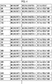
- Fig. 4 is a diagram showing molding information stored in the actual value storage unit according to the embodiment.
- the actual value storage unit 711 stores the mold unit 10, a set value of a controlled variable which is molding conditions of the molding product molded inside the mold unit 10, and an actual value of a physical amount relating to a manipulated variable operated such that the controlled variable is the set value, in association with each other.
- the controlled variable includes a movement position (or a movement distance indicating the movement position) of a movable member, a movement time of the movable member, a movement speed of the movable member, a force or a pressure applied to the movable member, or the like.
- the controlled variable includes a movement position or a movement speed of the crosshead 151 in the mold closing process, the mold clamping process, and the mold opening process, a holding pressure or a holding time of the molding material in the holding pressure process, the back pressure of the screw 330 in the plasticizing process, torque of the ejector motor 210 in the ejection process, or the like.
- the set value of the controlled variable is set for each mold unit 10.
- One set value of the controlled variable may be set for each mold unit 10.
- the set value of the controlled variable is input to the operation unit 750 or the like and is stored in the recording medium 702.
- the manipulated variable includes a supply current of a motor for driving the movable member, or the like.
- a combination of the movable member and the motor includes a combination of the crosshead 151 and the mold clamping motor 160, a combination of the ejector rod 230 and the ejector motor 210, a combination of the screw 330 and the injection motor 350, a combination of the screw 330 and the plasticizing motor 340, or the like.
- the physical amount relating to the manipulated variable means a physical amount which is changed according to the manipulated variable, in addition to the manipulated variable.
- the physical amount changed according to the manipulated variable includes torque of the motor or a temperature of the motor.
- the torque of the motor or a heating value of the motor is proportional to the supply current of the motor.
- the actual value is detected by a detector such as a current detector, a torque detector, or a temperature detector.
- the actual value of the torque of the motor may be obtained from a control command value of an inverter which supplies the current to the motor.
- a type of the physical amount relating to the manipulated variable may be selectable on the operation screen.
- the actual value of the physical amount relating to the manipulated variable may be a waveform, a peak value, or a value when the movable member exists at a specific position, or may be selectable on the operation screen.
- the actual value storage unit 711 monitors the actual value of the physical amount relating to the manipulated variable while the injection molding machine performs the molding operation and stores a monitoring result and the set value of the controlled variable, in association with each other.
- the storage may be performed while a predetermined mode is selected on the operation screen.
- a user who selects the predetermined mode may be a user of a delivery destination of the injection molding machine or a maintenance manager of a manufacturer of the injection molding machine. In the latter case, the maintenance manager selects the predetermined mode in order to determine presence or absence of abnormality in the injection molding machine in a periodic inspection of the injection molding machine or the like.
- the controlled variable of the present embodiment is the physical amount of the movable member.
- the present invention is not limited to this.
- the controlled variable may be a temperature of the mold unit 10, a temperature of the cylinder 310, or the like.
- the manipulated variable is the supply current of the heating unit 313.
- the presence or absence of the abnormality caused by deterioration of the injection molding machine or the mold unit 10 can be determined by a temporal change of the actual value of the physical amount (hereinafter, simply referred to as a "feature amount") relating to the manipulated variable.
- a feature amount relating to the manipulated variable.
- the injection molding machine or the mold unit 10 gently deteriorates, and thus, the actual value of the feature amount is gently changed. Accordingly, in the determination of the presence or absence of the abnormality causedby the deterioration, the actual values of the feature amounts between a plurality of shots, which have time gaps, are compared with each other.
- the change of the actual value of the feature amount includes the change of the actual value caused by the change of the molding conditions and the change of the actual value caused by the deterioration of the injection molding machine or the mold unit 10.
- the controller 700 includes an actual value extraction unit 712 which extracts the actual value of the feature amount in a plurality of shots performed under the same molding conditions, from the molding information stored in the molding value storage unit 711.
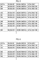
- Fig. 5 is a diagram showing the molding information extracted by the actual value extraction unit according to the embodiment.
- the actual value extraction unit 712 may extract the actual values of the feature amounts in the plurality of shots performed under the same molding conditions A, from the molding information (the molding information shown in Fig. 4 ) stored in the actual value storage unit 711.
- Fig. 6 is a diagram showing other molding information extracted by the actual value extraction unit according to the embodiment.
- the actual value extraction unit 712 may extract the actual values of the feature amounts in the plurality of shots performed under the same molding conditions B, from the molding information (the molding information shown in Fig. 4 ) stored in the actual value storage unit 711.
- Fig. 7 is a diagram showing other molding information extracted by the actual value extraction unit according to the embodiment.
- the actual value extraction unit 712 may extract the actual values of the feature amounts in the plurality of shots performed under the same molding conditions C, from the molding information (the molding information shown in Fig. 4 ) stored in the actual value storage unit 711.
- the actual values of the feature amounts in the plurality of shots performed under the same molding conditions are extracted, and thus, it is possible to eliminate the changes of the actual value caused by the change of the molding conditions from the changes of the actual values of the feature amounts. Accordingly, it is possible to determine the presence or absence of the abnormality by comparing the actual values of the feature amounts.
- the actual value extraction unit 712 of the present embodiment extracted the actual values of the plurality of shots performed under the same molding conditions.
- the actual value extraction unit 712 may extract the actual values of the feature amounts in the plurality of shots performed under similar molding conditions.
- the actual value extraction unit 712 may extract the actual values of the feature amounts in the plurality of shots performed under the similar molding conditions .
- the actual value extraction unit 712 may extract the actual values of the feature amounts in the plurality of shots performed under at least one of the same molding conditions and the similar molding conditions.
- whether or not the molding conditions are similar as each other can be determined based on whether or not the set value of the controlled variable is within an allowable range or whether or not the actual value (so-called logging data) of the physical amount used for managing the molding operation is within an allowable range.
- the physical amount used for managing the molding operation includes a position, a pressure, a force, a temperature, or the like, in addition to a time such as the molding cycle time, a mold closing time, a mold opening time, a filling time, or a plasticizing time.
- the physical amount used for determining similarity of the molding conditions may be selectable on the operation screen.
- the controller 700 may include an actual value comparison unit 713 which compares the actual values of the feature amounts in the plurality of shots which are extracted from the actual value extraction unit 712 and are performed under the same molding conditions, with each other.
- the actual value comparison unit 713 compares the actual value of the feature amount in a reference shot performed under the same molding conditions and the actual values of the feature amounts in other shots performed under the same molding conditions .
- the comparison of the actual values is performed by obtaining a size of difference of the actual values. It is possible to determine the presence or absence of the abnormality by comparing the actual values of the feature amounts .
- the actual value of the feature amount in the reference shot is used for the determination of the presence or absence of the abnormality, and thus, a trouble of preparing reference data based on simulation, experience, or the like can be omitted.
- the reference shot may be a past shot of other shots to be compared and may be selected on the operation screen.
- the reference shot may be a shot at the time of shipment inspection at the manufacturer of the injection molding machine or may be a shot at the time of the injection molding at the delivery destination of the injection molding machine. In the latter case, it is preferable that the reference shot is as early as possible from the delivery of the injection molding machine. It is possible to compare the actual values of the feature amounts which have time gaps, and thus, the presence or absence of the abnormality is easily determined.
- Fig. 8 is a graph showing a waveform of actual values of torque of the mold clamping motor compared by the actual value comparison unit according to the embodiment.
- a vertical axis indicates the actual value of the torque of the mold clamping motor 160
- a horizontal axis indicates an elapsed time after the mold closing starts.
- a fact that the actual value of the torque of the mold clamping motor 160 is positive means that a current flows from the inverter, which supplies the current to the mold clamping motor 160, to the mold clamping motor 160.
- a fact that the actual value of the torque of the mold clamping motor 160 is negative means that the current flows from the mold clamping motor 160 to the inverter due to deceleration of the mold clamping motor 160.
- a two-dot chain line indicates a waveform of the torque of the mold clamping motor 160 in the reference shot
- a solid line indicates a waveform of the torque of the mold clamping motor 160 in another shot.
- the actual value comparison unit 713 compares the actual values of the feature amounts of the plurality of shots which are performed before and after exchanging the mold unit 10 and are performed under the same molding conditions, with each other. For example, in a case where the actual value comparison unit 713 compares Shot No. 0001 and Shot No. 6000 performed under the same molding conditions A with each other, as shown in Fig. 4 , a mold exchange from the mold unit A to the mold unit B, an exchange from the mold unit B to the mold unit C, an exchange from the mold unit C to the mold unit A, an exchange from the mold unit A to the mold unit C, and an exchange from the mold unit C to the mold unit A are performed between the Shot No. 0001 and the Shot No. 6000.
- the actual values of the feature amounts which have time gaps, and thus, the presence or absence of the abnormality is easily determined.
- the actual value comparison unit 713 of the present embodiment may compare the actual values of the feature amounts of the plurality of shots performed under the same molding conditions, with each other.
- the actual value comparison unit 713 may compare the actual values of the feature amounts in the plurality of shots performed under the similar molding conditions, with other.
- the shot performed under the similar molding conditions may be the reference shot.
- the actual value comparison unit 713 may compare the actual values of the feature amounts in the plurality of shots performed under at least one of the same molding conditions and the similar molding conditions, with each other.
- Fig. 9 is a diagram showing a comparison result of the actual value comparison unit according to the embodiment for one molding conditions.
- a horizontal axis indicates a cumulative number of the shots performed under the same molding conditions
- a vertical axis indicates an elapsed time from the mold closing start in each shot.
- a gradation of white and black represents the size of the difference between the actual value of the feature amount in the reference shot and the actual values of the feature amounts in other shots, and as a color tone goes from white to black, the more a color tone goes from white to black, the larger the difference between the actual value of the feature amount in reference shot and the actual values of the feature amounts in other shots.
- the comparison result of the actual value comparison unit 713 may be indicated by the size of the difference between the actual value of the feature amount in the reference shot performed under the same molding conditions and the actual values of the feature amounts in the other shots performed under the same molding conditions.
- the comparison result shown in Fig. 9 may be displayed on the display unit 760.
- the user of the injection molding machine who views the display can know the shot number where the size of difference of the actual values of the feature amounts between the plurality of shots is large, the elapsed time after the mold closing starts, or the like, and it is possible to obtain information useful for estimating a cause of deterioration.
- Fig. 10 is a graph showing a comparison result of the actual value comparison unit according to the embodiment for a plurality of molding conditions.
- the actual value comparison unit 713 obtains a timing at which the size of the difference of the actual value of the feature amount exceeds a threshold value, and the timing is indicated by a black thick line.
- the threshold value may be common to the determination of the presence or absence of the abnormality caused by the deterioration of injection molding machine and the determination of the presence or absence of the abnormality caused by the deterioration of mold unit.
- the threshold value may be prepared for each molding condition.
- the comparison result shown in Fig. 10 may be displayed on the display unit 760.
- the user of the injection molding machine who views the display can know the time at which the abnormality occurs by the deterioration of the injection molding machine or the timing at which the abnormality occurs by the deterioration of the mold unit, and it is possible to obtain information useful for estimating a cause of deterioration.
- the controller 700 may include an injection molding machine abnormality determination unit 714 which determines the presence or absence of the abnormality caused by the deterioration of the injection molding machine, based on the comparison result of the actual value comparison unit 713.
- the injection molding machine abnormality determination unit 714 determines the presence or absence of the abnormality caused by the deterioration of the injection molding machine, based on the comparison result shown in Fig. 10 .
- the size of the difference may exceed the threshold value immediately before and immediately after the mold unit 10 is exchanged.
- the mold unit 10 is exchanged between Shot No. 6000 and Shot No. 6001, and the size of the difference exceeds the threshold value immediately before and immediately after the exchange.
- the injection molding machine abnormality determination unit 714 may determine that there is no abnormality caused by the deterioration of the injection molding machine.
- the injection molding machine abnormality determination unit 714 may determine the presence or absence of the abnormality caused by the deterioration of the current injection molding machine.
- the actual value extraction unit 712 may extract the past actual value performed under the same or similar molding conditions as the molding conformation used for the injection molding, and the injection molding machine abnormality determination unit 714 may determine the presence or absence of the abnormality caused by the deterioration of the injection molding machine during the injection molding using the actual value extracted by the actual value extraction unit 712 as reference data.
- the controller 700 may have a mold unit abnormality determination unit 715 which determines the presence or absence of the abnormality caused by the deterioration of the mold unit 10 based on the comparison result of the actual value comparison unit 713.
- the mold unit abnormality determination unit 715 determines the presence or absence of the abnormality caused by the deterioration of the mold unit 10, based on the comparison result shown in Fig. 10 .
- the size of the difference exceeds the threshold value immediately before the mold unit 10 is exchanged.
- the size of the difference may be less than or equal to the threshold value immediately after the mold unit 10 is exchanged.
- the mold unit 10 is exchanged between Shot No. 5000 and Shot No. 5001, and the size of the difference exceeds the threshold value immediately after the exchange.
- the size of the difference is less than or equal to the threshold value immediately after the exchange. In this case, it is determined that there is an abnormality in the mold unit C immediately before the exchange. This is because the probability of rapid deterioration of the injection molding machine during the exchange is very small.
- the size of the difference is less than or equal to the threshold value immediately before the mold unit 10 is exchanged.
- the size of the difference may exceed the threshold value immediately after the mold unit 10 is exchanged. In this case, it is determined that there is an abnormality in the mold unit immediately after the exchange. This is because the probability of rapid deterioration of the injection molding machine during the exchange is very small.
- the mold unit abnormality determination unit 715 may determine that there is no abnormality causedby the deterioration of the mold unit 10 in the case where the size of the difference is equal to or less than the threshold value.
- the mold unit abnormality determination unit 715 may determine the presence or absence of the abnormality caused by the deterioration of the current mold unit.
- the actual value extraction unit 712 may extract the past actual value performed under the same or similar molding conditions as the molding conformation used for the injection molding, and the mold unit abnormality determination unit 715 may determine the presence or absence of the abnormality caused by the deterioration of the mold unit 10 during the injection molding using the actual value extracted by the actual value extraction unit 712 as reference data.
- the threshold value which determines that there is abnormality caused by the degradation of the injection molding machine and the threshold value which determines that there is abnormality caused by the deterioration of the mold unit are common to each other .
- both threshold values may be separately prepared.
- a plurality of threshold values may be prepared so as to determine a degree of the abnormality.
- the injection molding machine abnormality determination unit 714 may determine the degree of the abnormality caused by the deterioration of the injection molding machine.
- the degree of the abnormality caused by the deterioration of the injection molding machine is obtained from the size of the difference of the actual values of the feature amounts, and the larger the size of the difference of the actual values of the feature amounts is, the larger the degree of the abnormality caused by the deterioration of the injection molding machine is.
- the degree of the abnormality caused by the deterioration of the injection molding machine may be represented by a numerical value or the like.
- the mold unit abnormality determination unit 715 may determine the degree of the abnormality caused by the deterioration of the mold unit 10.
- the degree of the abnormality caused by the deterioration of the mold unit 10 is obtained from the size of difference of the actual values of the feature amounts, and the larger the size of the difference of the actual values of the feature amounts is, the greater the degree of the abnormality caused by the deterioration of the mold unit 10 is.
- the degree of the abnormality caused by the deterioration of the mold unit 10 may be represented by a numerical value or the like.
- the controller 700 may include a display processing unit 716 which displays the comparison result of the actual value comparison unit 713.
- the display processing unit 716 displays the comparison result shown in Fig. 9 or the comparison result shown in Fig. 10 on the display unit 760.
- the user who views the display unit 760 can determine the presence or absence of the abnormality causedby the deterioration of the injection molding machine or the mold unit.
- the display processing unit 716 may display the determination result of the injection molding machine abnormality determination unit 714.
- the display processing unit 716 may display the determination result of the mold unit abnormality determination unit 715.
Landscapes
- Engineering & Computer Science (AREA)
- Manufacturing & Machinery (AREA)
- Mechanical Engineering (AREA)
- Injection Moulding Of Plastics Or The Like (AREA)
Abstract
Description
- Certain embodiment of the present invention relates to an injection molding machine and an injection molding information processing device.
- Priority is claimed to Japanese Patent Application No.
2017-073150, filed March 31, 2017 - A quality management device described in Japanese Unexamined Patent Application Publication No.
64-14015 - Meanwhile, if a mold unit is replaced, a set value of a controlled variable is changed, and thus, an actual value of a physical amount with respect to a manipulated variable is changed.
- Accordingly, it is difficult to determine presence or absence of abnormality by comparing the actual values of the physical amount relating to the manipulated variable with each other.
- The present invention is made in consideration of the above-described problem, and an object thereof is to provide an injection molding machine capable of determining presence of absence of abnormality by comparing actual values of a physical amount relating to a manipulated variable with each other.
- In order to achieve the above-described object, according to an aspect of the present invention, there is provided an injection molding machine, including: an injection molding information processing device which processes information relating to injection molding, in which the injection molding information processing device includes an actual value storage unit which, for each mold unit attached to the injection molding machine, stores molding information in which a set amount of a controlled variable which is molding conditions and an actual value of a physical amount relating to a manipulated variable for operating such that the controlled variable is the set value are associated with each other, and an actual value extraction unit which extracts the actual values of a plurality of shots performed under at least one of the same molding conditions and similar molding conditions, from the molding information stored in the actual value storage unit.
- According to the aspect of the present invention, an injection molding machine capable of determining presence of absence of abnormality by comparing actual values of the physical amount relating to the manipulated variable with each other is provided.
-
-
Fig. 1 is a view showing a state when a mold opening of an injection molding machine according to an embodiment is completed. -
Fig. 2 is a view showing a state when a mold of the injection molding machine according to the embodiment is clamped. -
Fig. 3 is a functional block diagram showing components of a controller according to an embodiment. -
Fig. 4 is a diagram showing molding information stored in an actual value storage unit according to the embodiment. -
Fig. 5 is a diagram showing molding information extracted by an actual value extraction unit according to the embodiment. -
Fig. 6 is a diagram showing other molding information extracted by the actual value extraction unit according to the embodiment. -
Fig. 7 is a diagram showing other molding information extracted by the actual value extraction unit according to the embodiment. -
Fig. 8 is a graph showing a waveform of actual values of torque of a mold clamping motor compared by an actual value comparison unit according to the embodiment. -
Fig. 9 is a diagram showing a comparison result of the actual value comparison unit according to the embodiment for one molding condition. -
Fig. 10 is a graph showing a comparison result of the actual value comparison unit according to the embodiment for a plurality of molding conditions. - Hereinafter, an embodiment of the present invention is described with reference to the drawings. However, in each drawing, the same or corresponding reference numerals are assigned to the same or corresponding configurations, and descriptions thereof are omitted.
-
Fig. 1 is a view showing a state when a mold opening of an injection molding machine according to an embodiment is completed.Fig. 2 is a view showing a state when a mold of the injection molding machine according to the embodiment is clamped. As shown inFigs. 1 and2 , the injection molding machines include amold clamping unit 100, anejector unit 200, aninjection unit 300, amovement unit 400, and acontroller 700. Hereinafter, each component of the injection molding machine will be described. - In descriptions of the
mold clamping unit 100, a movement direction (right direction inFigs. 1 and2 ) of amovable platen 120 when a mold is closed is defined as a front side, and a movement direction (left direction inFigs. 1 and2 ) of themovable platen 120 when the mold is open is defined as a rear side. - The
mold clamping unit 100 performs closing, clamping, and opening on amold unit 10. For example, themold clamping unit 100 is a horizontal type clamping unit and moldopening and closing directions are a horizontal direction. Themold clamping unit 100 includes astationary platen 110, themovable platen 120, atoggle support 130, atie bar 140, atoggle mechanism 150, amold clamping motor 160, amotion conversion mechanism 170, and a moldspace adjustment mechanism 180. - The
stationary platen 110 is fixed to the frame Fr. Astationary mold 11 is attached to a surface of thestationary platen 110 facing themovable platen 120. - The
movable platen 120 is movable in the mold opening and closing directions with respect to the frame Fr. Aguide 101 which guides themovable platen 120 is placed on the frame Fr. Amovable mold 12 is attached to a surface of themovable platen 120 facing thestationary platen 110. - The
movable platen 120 is moved forward or rearward with respect to thestationary platen 110, and thus, closing, clamping, and opening of the mold are performed. Themold unit 10 is configured of thestationary mold 11 and themovable mold 12. - The
toggle support 130 is connected to thestationary platen 110 with a gap therebetween, and is placed on the frame Fr to be movable in mold opening and closing directions . In addition, thetoggle support 130 may be movable along a guide which is placed on the frame Fr. The guide of thetoggle support 130 may be also used as theguide 101 of themovable platen 120. - In addition, in the present embodiment, the
stationary platen 110 is fixed to the frame Fr, and thetoggle support 130 is movable in the mold opening and closing directions with respect to the frame Fr. However, thetoggle support 130 may be fixed to the frame Fr, and thestationary platen 110 may be movable in the mold opening and closing directions with respect to the frame Fr. - The
stationary platen 110 and thetoggle support 130 are connected to each other with a gap L in the mold opening and closing directions by thetie bar 140. Aplurality of (for example, four)tie bars 140 may be used. Thetie bars 140 are parallel in the mold opening and closing directions and extend according to a mold clamping force. A tiebar strain detector 141 which detects strain of thetie bar 140 may be provided in at least onetie bar 140. The tiebar strain detector 141 sends signals indicating the detection results to thecontroller 700. The detection results of the tiebar strain detector 141 are used for detection or the like of the mold clamping force. - In addition, in the present embodiment, the tie
bar strain detector 141 is used as a mold clamping force detector which detects the mold clamping force. However, the present invention is not limited to this. The mold clamping force detector is not limited to a strain gauge type detector, and may be a piezoelectric type detector, a capacitance type detector, a hydraulic type detector, an electromagnetic type detector, or the like, and the attachment position of the mold clamping force detector is also not limited to thetie bar 140. - The
toggle mechanism 150 is disposed between themovable platen 120 and thetoggle support 130 and moves themovable platen 120 in the mold opening and closing directions with respect to thetoggle support 130. Thetoggle mechanism 150 is configured of a crosshead 151, a pair of link groups, or the like. Each link group includes afirst link 152 and asecond link 153 which are bendably/strechably connected to each other by pins or the like. Thefirst link 152 is attached to themovable platen 120 so as to be oscillated by pins or the like and thesecond link 153 is attached to thetoggle support 130 so as to be oscillated by pins or the like. Thesecond link 153 is attached to the crosshead 151 via a third link 154. If the crosshead 151 is moved forward or rearward with respect to thetoggle support 130, thefirst link 152 and thesecond link 153 are bent and stretched and themovable platen 120 is moved forward or rearward with respect to thetoggle support 130. - In addition, the configuration of the
toggle mechanism 150 is not limited to the configuration shown inFigs. 1 and2 . For example, inFigs. 1 and2 , the number of nodes of each link group is five. However, the number of nodes may be four, and one end portion of the third link 154 may be connected to a node between thefirst link 152 and thesecond link 153. - The
mold clamping motor 160 is attached to thetoggle support 130 and operates thetoggle mechanism 150. Themold clamping motor 160 moves the crosshead 151 forward or rearward with respect to thetoggle support 130, and thus, thefirst links 152 and thesecond links 153 are bent and stretched, and themovable platen 120 is moved forward or rearward with respect to thetoggle support 130. Themold clamping motor 160 is directly connected to themotion conversion mechanism 170. However, themold clamping motor 160 may be connected to themotion conversion mechanism 170 via a belt, a pulley, or the like. - The
motion conversion mechanism 170 converts a rotary motion of themold clamping motor 160 into a linear motion of the crosshead 151. Themotion conversion mechanism 170 includes ascrew shaft 171 and ascrew nut 172 which is screwed to thescrew shaft 171. A ball or a roller may be interposed between thescrew shaft 171 and thescrew nut 172. - The
mold clamping unit 100 performs a mold closing process, a mold clamping process, a mold opening process, or the like under the control of thecontroller 700. - In the mold closing process, the
mold clamping motor 160 is driven to move the crosshead 151 forward to a mold closing completion position at a set speed. Accordingly, themovable platen 120 is moved forward and themovable mold 12 comes into contact with thestationary mold 11. For example, a position or speed of the crosshead 151 is detected using a mold clampingmotor encoder 161 or the like. The mold clampingmotor encoder 161 detects the rotation of themold clamping motor 160 and sends signals indicating the detection results to thecontroller 700. - In the mold clamping process, the
mold clamping motor 160 is further driven to further move the crosshead 151 forward from the mold closing completion position to a mold clamping position, and thus, a mold clamping force is generated. When the mold is clamped, acavity space 14 is formed between themovable mold 12 and thestationary mold 11, and thecavity space 14 is filled with a liquid molding material by theinjection unit 300. A filled molding material is solidified, and thus, a molding product is obtained. A plurality ofcavity spaces 14 may be provided, and in this case, a plurality of molding products maybe simultaneously obtained. - In the mold opening process, the
mold clamping motor 160 is driven to move the crosshead 151 rearward to a mold opening completion position at a set speed. Accordingly, themovable platen 120 is moved rearward, and themovable mold 12 is separated from thestationary mold 11. Thereafter, theejector unit 200 ejects the molding product from themovable mold 12. - Setting conditions in the mold closing process and the mold clamping process are collectively set as a series of setting conditions. For example, a speed or positions (including a speed switching position, a mold closing completion position, and a mold clamping position) of the crosshead 151 in the mold closing process and the mold clamping process are collectively set as a series of setting conditions . In addition, instead of the speed, the positions, or the like of the crosshead 151, a speed, positions, or the like of the
movable platen 120 maybe set. Moreover, instead of the position (for example, the mold clamping position) of the crosshead or the position of the movable platen, the mold clamping force may be set. - Meanwhile, the
toggle mechanism 150 amplifies a driving force of themold clamping motor 160 and transmits the driving force to themovable platen 120. An amplification magnification of thetoggle mechanism 150 is also referred to as a toggle magnification. The toggle magnification is changed according to an angle θ (hereinafter, also referred to a "link angle θ") between thefirst link 152 and thesecond link 153. The link angle θ is obtained from the position of the crosshead 151. When the link angle θ is 180°, the toggle magnification becomes the maximum value. - In a case where a space of the
mold unit 10 is changed by replacement of themold unit 10, a temperature change of themold unit 10, or the like, a mold space adjustment is performed such that a predetermined mold clamping force is obtained when the mold is clamped. For example, in the mold space adjustment, the gap L between thestationary platen 110 and thetoggle support 130 is adjusted such that the link angle θ of thetoggle mechanism 150 becomes a predetermined angle at the time of a mold touch where themovable mold 12 comes into contact with thestationary mold 11. - The
mold clamping unit 100 includes the moldspace adjustment mechanism 180 which performs the mold space adjustment by adjusting the gap L between thestationary platen 110 and thetoggle support 130. The moldspace adjustment mechanism 180 includes ascrew shaft 181 which is formed on a rear end portion of thetie bar 140, ascrew nut 182 which is rotatably supported by thetoggle support 130, and a moldspace adjustment motor 183 which rotates thescrew nut 182 screwed to thescrew shaft 181. - The
screw shaft 181 and thescrew nut 182 are provided for eachtie bar 140. A rotation of the moldspace adjustment motor 183 may be transmitted to a plurality ofscrew nuts 182 via arotation transmission portion 185. The plurality ofscrew nuts 182 can be synchronously rotated. In addition, it is possible to rotate the plurality ofscrew nuts 182 individually by changing a transmission path of therotation transmission portion 185. - For example, the
rotation transmission portion 185 is configured of a gear or the like. In this case, a driven gear is formed on an outer periphery of eachscrew nut 182, a drive gear is attached to an output shaft of the moldspace adjustment motor 183, and an intermediate gear which engages with a plurality of driven gears and drive gears is rotatably held by a center portion of thetoggle support 130. In addition, therotation transmission portion 185 may be configured of a belt, a pulley, or the like instead of the gear. - An operation of the mold
space adjustment mechanism 180 is controlled by thecontroller 700. Thecontroller 700 drives the moldspace adjustment motor 183 to rotate thescrew nut 182, and thus, the position of thetoggle support 130 which rotatably holds thescrew nut 182 with respect to thestationary platen 110 is adjusted, and the gap L between thestationary platen 110 and thetoggle support 130 is adjusted. - In addition, in the present embodiment, the
screw nut 182 is rotatably held with respect to thetoggle support 130 and thetie bar 140 in which thescrew shaft 181 is formed is fixed to thestationary platen 110. However, the present invention is not limited to this. - For example, the
screw nut 182 may be rotatably held with respect to thestationary platen 110 and thetie bar 140 may be fixed to thetoggle support 130. In this case, the gap L can be adjusted by rotating thescrew nut 182. - Moreover, the
screw nut 182 maybe fixed to thetoggle support 130 and thetie bar 140 may be rotatably held with respect to thestationary platen 110. In this case, the gap L can be adjusted by rotating thetie bar 140. - Moreover, the
screw nut 182 may be fixed to thestationary platen 110 and thetie bar 140 may be rotatably held with respect to thetoggle support 130. In this case, the gap L can be adjusted by rotating thetie bar 140. - The gap L is detected using a mold space
adjustment motor encoder 184. The mold spaceadjustment motor encoder 184 detects a rotation amount or a rotation direction of the moldspace adjustment motor 183 and sends signals indicating the detection results to thecontroller 700. The detection results of the mold spaceadjustment motor encoder 184 are used to monitor or control the position of thetoggle support 130 or the gap L. - The mold
space adjustment mechanism 180 rotates one of thescrew shaft 181 and thescrew nut 182 which are screwed to each other to adjust the gap L. A plurality of moldspace adjustment mechanisms 180 maybe used, and a plurality of moldspace adjustment motors 183 may be used. - Moreover, in order to adjust the gap L, the mold
space adjustment mechanism 180 of the present embodiment includes thescrew shaft 181 formed on thetie bar 140 and thescrew nut 182 screwed to thescrew shaft 181. However, the present invention is not limited to this. - For example, the mold
space adjustment mechanism 180 may include a tie bar temperature controller which controls the temperature of thetie bar 140. The tie bar temperature controller is attached to eachtie bar 140 and coordinates the temperatures of the plurality of tie bars 140. Thetie bar 140 is lengthened by heat expansion and the gap L increases as the temperature of thetie bar 140 increases. The temperatures of the plurality of tie bars 140 can be adjusted independently. - For example, the tie bar temperature controller includes a heating unit such as a heater and controls the temperature of the
tie bar 140 by heating. The tie bar temperature controller may include a cooler such as a water cooling jacket and may control the temperature of thetie bar 140 by cooling. The tie bar temperature controller may include both the heating unit and the cooler. - In addition, the
mold clamping unit 100 of the present embodiment is a horizontal type mold clamping unit in which the mold opening and closing directions are horizontal directions. However, themold clamping unit 100 may be a vertical type mold clamping unit in which the mold opening and closing directions are vertical directions. The vertical type mold clamping unit includes a lower platen, an upper platen, a toggle support, tie bars, a toggle mechanism, a mold clamping motor, or the like. Any one of the lower platen and the upper platen is used as a stationary platen and the other is used as a movable platen. A lower mold is attached to the lower platen and an upper mold is attached to the upper platen. The lower mold and the upper mold configure the mold unit. The lower mold may be attached to the lower platen via a rotary table. The toggle support is disposed below the lower platen and is connected to the upper platen via the tie bar. The upper platen and the toggle support are connected to each other in mold opening and closing directions by the tie bar with a gap therebetween. The toggle mechanism is disposed between the toggle support and the lower platen and lifts or lowers the movable platen. The mold clamping motor operates the toggle mechanism. In a case where the mold clamping unit is a vertical mold clamping unit, in general, the number of the tie bars is three. In addition, the number of the tie bars is not particularly limited. - In addition, the
mold clamping unit 100 of the present embodiment has themold clamping motor 160 as a drive source. However, themold clamping unit 100 may have a hydraulic cylinder instead of themold clamping motor 160. In addition, themold clamping unit 100 may have a linear motor for opening and closing a mold and may have an electromagnet for clamping a mold. - Similarly to the descriptions of the
mold clamping unit 100, in descriptions of theejector unit 200, the movement direction (right direction inFigs. 1 and2 ) of themovable platen 120 when the mold is closed is defined as the front side, and the movement direction (left direction inFigs. 1 and2 ) of themovable platen 120 when the mold is open is defined as the rear side. - The
ejector unit 200 ejects the molding product from themold unit 10. Theejector unit 200 includes anejector motor 210, amotion conversion mechanism 220, anejector rod 230, or the like. - The
ejector motor 210 is attached to themovable platen 120. Theejector motor 210 is directly connected to themotion conversion mechanism 220. However, theejector motor 210 may be connected to themotion conversion mechanism 220 via a belt, a pulley, or the like. - The
motion conversion mechanism 220 converts a rotary motion of theejector motor 210 into a linear motion of theejector rod 230. Themotion conversion mechanism 220 includes a screw shaft and a screw nut which is screwed to the screw shaft. A ball or a roller may be interposed between the screw shaft and the screw nut. - The
ejector rod 230 can be moved forward or rearward through a through-hole of themovable platen 120. A front end portion of theejector rod 230 comes into contact with amovable member 15 which is disposed to be movable forward or rearward inside themovable mold 12. The front end portion of theejector rod 230 maybe connected to themovable member 15 or may not be connected to themovable member 15. - The
ejector unit 200 performs an ejection process under the control of thecontroller 700. - In the ejection process, the
ejector motor 210 is driven to move theejector rod 230 forward from a standby position to an ejection position at a set speed, and thus, themovable member 15 is moved forward and the molding product is ejected. Thereafter, theejector motor 210 is driven to move theejector rod 230 rearward at a set speed, and thus, themovable member 15 is moved rearward to an original standby position. For example, a position or speed of theejector rod 230 is detected using anejector motor encoder 211. Theejector motor encoder 211 detects the rotation of theejector motor 210 and sends signals indicating the detection results to thecontroller 700. - Unlike the descriptions of the
mold clamping unit 100 or the descriptions of theejector unit 200, in descriptions of theinjection unit 300, a movement direction (left direction inFigs. 1 and2 ) of ascrew 330 during filling is referred to as a front side, and a movement direction (right direction inFigs. 1 and2 ) of thescrew 330 during plasticizing is referred to as a rear side. - The
injection unit 300 is installed on aslide base 301 which is movable forward or rearward with respect to the frame Fr, and is movable forward or rearward with respect to themold unit 10. Theinjection unit 300 comes into contact with themold unit 10, and thus, thecavity space 14 inside themold unit 10 is filled with the molding material. For example, theinjection unit 300 includes acylinder 310, anozzle 320, thescrew 330, aplasticizing motor 340, aninjection motor 350, apressure detector 360, or the like. - The
cylinder 310 heats the molding material which is supplied from asupply port 311 to the inner portion of thecylinder 310. Thesupply port 311 is formed on a rear portion of thecylinder 310. A cooler 312 such as a water cooling cylinder is provided on an outer periphery of the rear portion of thecylinder 310. Aheating unit 313 such as a band heater and thetemperature detector 314 are provided on an outer periphery of thecylinder 310 on a front side of the cooler 312. - The
cylinder 310 is divided into a plurality of zones in an axial direction (right and left directions inFigs. 1 and2 ) of thecylinder 310. Theheating unit 313 and thetemperature detector 314 are provided in each zone. Thecontroller 700 controls theheating unit 313 such that a detection temperature of thetemperature detector 314 for each zone becomes a set temperature. - The
nozzle 320 is provided on the front end portion of thecylinder 310 and presses themold unit 10. Theheating unit 313 and thetemperature detector 314 are provided on an outer periphery of thenozzle 320. Thecontroller 700 controls theheating unit 313 such that a detection temperature of thenozzle 320 becomes a set temperature. - The
screw 330 is disposed in thecylinder 310 so as to be rotatable and movable forward or rearward. If thescrew 330 rotates, the molding material is fed forward along spiral grooves of thescrew 330. The molding material is gradually melted by heat from thecylinder 310 while being fed forward. The liquid molding material is fed to a front portion of thescrew 330 and is accumulated in the front portion of thecylinder 310, and thus, thescrew 330 is moved rearward. Thereafter, if thescrew 330 is moved forward, the liquid molding material accumulated in front of thescrew 330 is injected from thenozzle 320 and the inside of themold unit 10 is filled with the liquid molding material. - A
backflow prevention ring 331 is attached to a front portion of thescrew 330 to be movable forward or rearward as a backflow prevention valve which prevents a backflow of the molding material from the front side of thescrew 330 toward the rear side when thescrew 330 is pushed forward. - When the
screw 330 is moved forward, thebackflow prevention ring 331 is pushed toward the rear side by the pressure of the molding material in front of thescrew 330 and is moved rearward relative to thescrew 330 to a close position (refer toFig. 2 ) at which a flow path of the molding material is closed. Accordingly, the molding material accumulated in front of thescrew 330 is prevented from flowing toward the rear side. - Meanwhile, when the
screw 330 rotates, thebackflow prevention ring 331 is pushed toward the front side by the pressure of the molding material fed forward along the spiral grooves of thescrew 330 and is moved forward relative to thescrew 330 to an open position (refer toFig. 1 ) at which the flow path of the molding material is open. Accordingly, the molding material is fed to the front side of thescrew 330. - The
backflow prevention ring 331 may be either a co-rotation type ring which rotates together with thescrew 330 or a non-co-rotation type ring which does not rotate together with thescrew 330. - In addition, the
injection unit 300 may include a drive source which moves thebackflow prevention ring 331 forward or rearward relative to thescrew 330 between the open position and the close position. - The
plasticizing motor 340 rotates thescrew 330. A drive source which rotates thescrew 330 is not limited to theplasticizing motor 340 and may be a hydraulic pump or the like, for example. - The
injection motor 350 moves thescrew 330 forward or rearward. A motion conversion mechanism or the like which converts a rotary motion of theinjection motor 350 into a linear motion of thescrew 330 is provided between theinjection motor 350 and thescrew 330. For example, the motion conversion mechanism includes a screw shaft and a screw nut which is screwed to the screw shaft. A ball, a roller, or the like may be provided between the screw shaft and the screw nut. A drive source which moves thescrew 330 forward or rearward is not limited to theinjection motor 350 and may be a hydraulic cylinder or the like, for example. - The
pressure detector 360 detects a pressure transmitted between theinjection motor 350 and thescrew 330. Thepressure detector 360 is provided on a pressure transmission path between theinjection motor 350 and thescrew 330 and detects a pressure applied to thepressure detector 360. - The
pressure detector 360 sends signals indicating the detection results to thecontroller 700. The detection results of thepressure detector 360 are used to control or monitor a pressure received by thescrew 330 from the molding material, a back pressure with respect to thescrew 330, a pressure applied from thescrew 330 to the molding material, or the like. - The
injection unit 300 performs a filling process, a holding pressure process, a plasticizing process, or the like under the control of thecontroller 700. - In the filling process, the
injection motor 350 is driven to move thescrew 330 forward at a set speed, and thecavity space 14 inside themold unit 10 is filled with the liquid molding material accumulated in front of thescrew 330. For example, a position or speed of thescrew 330 is detected using aninjection motor encoder 351. Theinjection motor encoder 351 detects the rotation of theinjection motor 350 and sends signals indicating the detection results to thecontroller 700. If the position of thescrew 330 reaches a set position, switching (so called V/P switching) from the filling process to the holding pressure process is performed. The position at which the V/P switching is performed is also referred to a V/P switching position. The set speed of thescrew 330 may be changed according to the position of thescrew 330, the time, or the like. - Moreover, in the filling process, after the position of the
screw 330 reaches the set position, thescrew 330 may temporarily stop at the set position, and thereafter, the V/P switching may be performed. Immediately before the V/P switching, instead of stopping thescrew 330, thescrew 330 may be moved forward or may be moved rearward at a very slow speed. - In the holding pressure process, the
injection motor 350 is driven to push thescrew 330 forward, a pressure (hereinafter, also referred to as a "holding pressure") of the molding material on a front end portion of thescrew 330 is held at a set pressure, and the molding material remaining inside thecylinder 310 is pressed toward themold unit 10. Insufficient molding materials can be replenished by cooling shrinkage in themold unit 10. For example, the holding pressure is detected using thepressure detector 360. Thepressure detector 360 sends signals indicating the detection results to thecontroller 700. A set value of the holding pressure may be changed according to an elapsed time from the starting of the holding pressure process, or the like. - In the holding pressure process, the molding material inside the
cavity space 14 in themold unit 10 is gradually cooled, and when the holding pressure process is completed, an inlet of thecavity space 14 is closed by the molding material which is solidified. This state is referred to as a gate seal, and a backflow of the molding material from thecavity space 14 is prevented. After the holding pressure process, a cooling process starts. In the cooling process, solidification of the molding material in thecavity space 14 is performed. In order to shorten a molding cycle time, the plasticizing process may be performed during the cooling process. - In the plasticizing process, the
plasticizing motor 340 is driven to rotate thescrew 330 at a set rotating speed and the molding material is fed forward along the spiral grooves of thescrew 330 by thescrew 330. According to this, the molding material is gradually melted. Thescrew 330 is moved rearward as the liquid molding material is fed to the front side of thescrew 330 and is accumulated in front of thecylinder 310. For example, the rotating speed of thescrew 330 is detected using aplasticizing motor encoder 341. Theplasticizing motor encoder 341 detects the rotation of theplasticizing motor 340 and sends signals indicating the detection results to thecontroller 700. - In the plasticizing process, in order to restrict an abrupt rearward movement of the
screw 330, theinjection motor 350 may be driven so as to apply a set back pressure to thescrew 330. For example, the back pressure with respect to thescrew 330 is detected using thepressure detector 360. Thepressure detector 360 sends signals indicating the detection results to thecontroller 700. If thescrew 330 is moved rearward to a plasticizing completion position and a predetermined amount of the molding materials is accumulated in front of thescrew 330, the plasticizing process is completed. - In addition, the
injection unit 300 of the present embodiment is an inline and screw type injection unit. However, theinjection unit 300 may be a preplasticizing type injection unit. The preplasticizing type injection unit supplies molten molding material inside a plasticizing cylinder to an injection cylinder and injects the molding material from the injection cylinder into the mold unit. A screw is disposed to be rotatable or rotatable and movable forward or rearward in the plasticizing cylinder and a plunger is disposed to be movable forward or rearward in the injection cylinder. - In addition, the
injection unit 300 of the present embodiment is a horizontal type injection unit in which the axial direction of thecylinder 310 is the horizontal direction. However, theinjection unit 300 may be a vertical type injection unit in which the axial direction of thecylinder 310 is a vertical direction. The mold clamping unit combined with the verticaltype injection unit 300 may be a vertical type mold clamping unit or a horizontal type mold injection unit. Similarly, the mold clamping unit combined with the horizontaltype injection unit 300 may be a horizontal type mold clamping unit or a vertical type mold clamping unit. - Similarly to the descriptions of the
injection unit 300, in descriptions of themovement unit 400, the movement direction (left direction inFigs. 1 and2 ) of thescrew 330 during filling is referred to as a front side, and the movement direction (right direction inFigs. 1 and2 ) of thescrew 330 during plasticizing is referred to as a rear side. - The
movement unit 400 moves theinjection unit 300 forward or rearward with respect to themold unit 10. In addition, themovement unit 400 presses thenozzle 320 to themold unit 10 to generate a nozzle touch pressure. Themovement unit 400 includes ahydraulic pump 410, amotor 420 which is a drive source, ahydraulic cylinder 430 which is a hydraulic actuator, or the like. - The
hydraulic pump 410 includes afirst port 411 and asecond port 412. Thehydraulic pump 410 is a pump which can rotate in both directions and switches a rotation direction of themotor 420. Accordingly, a working liquid (for example, oil) is sucked from any one offirst port 411 and thesecond port 412 and is discharged from the other, and thus, a liquid pressure is generated. In addition, thehydraulic pump 410 sucks the working liquid from a tank and can discharge the working liquid from any one of thefirst port 411 and thesecond port 412. - The
motor 420 operates thehydraulic pump 410. Themotor 420 drives thehydraulic pump 410 in the rotation direction and by rotation torque corresponding to the control signals from thecontroller 700. Themotor 420 may be an electric motor or an electric servo motor. - The
hydraulic cylinder 430 includes acylinder body 431, apiston 432, and apiston rod 433. Thecylinder body 431 is fixed to theinjection unit 300. Thepiston 432 divides the inside of thecylinder body 431 into afront chamber 435 which a first chamber and arear chamber 436 which is a second chamber. Thepiston rod 433 is fixed to thestationary platen 110. - The
front chamber 435 of thehydraulic cylinder 430 is connected to thefirst port 411 of thehydraulic pump 410 via afirst flow path 401. The working liquid discharged from thefirst port 411 is supplied to thefront chamber 435 via thefirst flow path 401, and thus, theinjection unit 300 is pushed forward. Theinjection unit 300 is moved forward, and thus, thenozzle 320 is pressed to thestationary mold 11. Thefront chamber 435 functions as a pressure chamber which generates the nozzle touch pressure of thenozzle 320 by the pressure of the working liquid supplied from thehydraulic pump 410. - Meanwhile, the
rear chamber 436 of thehydraulic cylinder 430 is connected to thesecond port 412 of thehydraulic pump 410 via asecond flow path 402. The working liquid discharged from thesecond port 412 is supplied to therear chamber 436 of thehydraulic cylinder 430 via thesecond flow path 402, and thus, theinjection unit 300 is pushed rearward. Theinjection unit 300 is moved rearward and thus, thenozzle 320 is separated from thestationary mold 11. - In addition, in the present embodiment, the
movement unit 400 includes thehydraulic cylinder 430. However, the present invention is not limited to this. For example, instead of thehydraulic cylinder 430, an electric motor and a motion conversion mechanism which converts a rotary motion of the electric motor into a linear motion of theinjection unit 300 may be used. - For example, as shown in
Figs. 1 and2 , thecontroller 700 includes a Central Processing Unit (CPU) 701, arecording medium 702 such as a memory, aninput interface 703, and anoutput interface 704. Thecontroller 700 performs various controls by causing theCPU 701 to execute a program stored in therecording medium 702. In addition, thecontroller 700 receives a signal from the outside through theinput interface 703 and transmits a signal to the outside through theoutput interface 704. - The
controller 700 repeatedly performs the mold closing process, the mold clamping process, the mold opening process, or the like to repeatedly manufacture the molding product. In addition, thecontroller 700 performs the plasticizing process, the filling process, the holding pressure process, or the like during the mold clamping process. A series of operations to obtain the molding product, for example, an operation from the start of the plasticizing process to the start of the next plasticizing process is referred to as "shot" or a "molding cycle" . In addition, a time required for once shot is also referred to as a "molding cycle time". - The
controller 700 is connected to anoperation unit 750 or thedisplay unit 760. Theoperation unit 750 receives an input operation from a user and outputs signals corresponding to the input operation to thecontroller 700. Thedisplay unit 760 displays an operation screen corresponding to the input operation of theoperation unit 750 under the control of thecontroller 700. - The operation screen is used for the setting of the injection molding machine or the like. A plurality of operation screens are provided, and thus, are displayed to be switched or to overlap each other. A user operates the
operation unit 750 while viewing the operation screen displayed by thedisplay unit 760 to perform the setting (including an input of a set value) of the injection molding machine or the like. - For example, the
operation unit 750 and thedisplay unit 760 may be configured of a touch panel to be integrated with each other. In addition, in the present embodiment, theoperation unit 750 and thedisplay unit 760 are integrated with each other. However, theoperation unit 750 and thedisplay unit 760 may be provided to be independent to each other. In addition, a plurality ofoperation units 750 may be provided. - The
controller 700 also serves as an injection molding information processing device for processing information relating to injection molding. In addition, the injection molding information processing device may be provided separately from thecontroller 700. In this case, in order to acquire various information from thecontroller 700, the injection molding information processing device may be connected to thecontroller 700 via a network such as a LAN (Local Area Network) or an internet line. The connection may be either a wired connection or a wireless connection. -
Fig. 3 is a functional block diagram showing components of the controller according to an embodiment. The functional blocks shown inFig. 3 are conceptual and do not necessarily have to be physically configured as shown. All functional blocks or some functional blocks can be configured so as to be dispersed or integrated functionally or physically in any unit. All processing functions or some processing functions performed in the functional blocks can be realized by a program executed by a CPU or can be realized as hardware by wired logic. - As shown in
Fig. 3 , thecontroller 700 includes an actualvalue storage unit 711 which, for eachmold unit 10 attached to the injection molding machine, stores a set value of a controlled variable which is molding conditions and an actual value of a physical amount relating to a manipulated variable for operating such that the controlled variable is the set value, in association with each other. -
Fig. 4 is a diagram showing molding information stored in the actual value storage unit according to the embodiment. As shown inFig. 4 , the actualvalue storage unit 711 stores themold unit 10, a set value of a controlled variable which is molding conditions of the molding product molded inside themold unit 10, and an actual value of a physical amount relating to a manipulated variable operated such that the controlled variable is the set value, in association with each other. - For example, the controlled variable includes a movement position (or a movement distance indicating the movement position) of a movable member, a movement time of the movable member, a movement speed of the movable member, a force or a pressure applied to the movable member, or the like. For example, the controlled variable includes a movement position or a movement speed of the crosshead 151 in the mold closing process, the mold clamping process, and the mold opening process, a holding pressure or a holding time of the molding material in the holding pressure process, the back pressure of the
screw 330 in the plasticizing process, torque of theejector motor 210 in the ejection process, or the like. - The set value of the controlled variable is set for each
mold unit 10. One set value of the controlled variable may be set for eachmold unit 10. The set value of the controlled variable is input to theoperation unit 750 or the like and is stored in therecording medium 702. - For example, the manipulated variable includes a supply current of a motor for driving the movable member, or the like. For example, a combination of the movable member and the motor includes a combination of the crosshead 151 and the
mold clamping motor 160, a combination of theejector rod 230 and theejector motor 210, a combination of thescrew 330 and theinjection motor 350, a combination of thescrew 330 and theplasticizing motor 340, or the like. - The physical amount relating to the manipulated variable means a physical amount which is changed according to the manipulated variable, in addition to the manipulated variable. In a case where the manipulated variable in the supply current of the motor, the physical amount changed according to the manipulated variable includes torque of the motor or a temperature of the motor. The torque of the motor or a heating value of the motor is proportional to the supply current of the motor. The actual value is detected by a detector such as a current detector, a torque detector, or a temperature detector. The actual value of the torque of the motor may be obtained from a control command value of an inverter which supplies the current to the motor.
- A type of the physical amount relating to the manipulated variable may be selectable on the operation screen. In addition, the actual value of the physical amount relating to the manipulated variable may be a waveform, a peak value, or a value when the movable member exists at a specific position, or may be selectable on the operation screen.
- The actual
value storage unit 711 monitors the actual value of the physical amount relating to the manipulated variable while the injection molding machine performs the molding operation and stores a monitoring result and the set value of the controlled variable, in association with each other. The storage may be performed while a predetermined mode is selected on the operation screen. A user who selects the predetermined mode may be a user of a delivery destination of the injection molding machine or a maintenance manager of a manufacturer of the injection molding machine. In the latter case, the maintenance manager selects the predetermined mode in order to determine presence or absence of abnormality in the injection molding machine in a periodic inspection of the injection molding machine or the like. - In addition, the controlled variable of the present embodiment is the physical amount of the movable member. However, the present invention is not limited to this. For example, the controlled variable may be a temperature of the
mold unit 10, a temperature of thecylinder 310, or the like. In a case where the controlled variable is the temperature of thecylinder 310, the manipulated variable is the supply current of theheating unit 313. - Meanwhile, the presence or absence of the abnormality caused by deterioration of the injection molding machine or the
mold unit 10 can be determined by a temporal change of the actual value of the physical amount (hereinafter, simply referred to as a "feature amount") relating to the manipulated variable. For example, as themold clamping unit 100 deteriorates, an energy loss required for controlling the position of the crosshead 151 increases, and thus, torque of themold clamping motor 160 increases. - The injection molding machine or the
mold unit 10 gently deteriorates, and thus, the actual value of the feature amount is gently changed. Accordingly, in the determination of the presence or absence of the abnormality causedby the deterioration, the actual values of the feature amounts between a plurality of shots, which have time gaps, are compared with each other. - As shown in
Fig. 4 , if themold unit 10 is exchanged, the molding conditions are changed, and thus, the actual value of the feature amount is changed. The change of the actual value of the feature amount includes the change of the actual value caused by the change of the molding conditions and the change of the actual value caused by the deterioration of the injection molding machine or themold unit 10. - Therefore, as shown in
Fig. 3 , thecontroller 700 includes an actualvalue extraction unit 712 which extracts the actual value of the feature amount in a plurality of shots performed under the same molding conditions, from the molding information stored in the moldingvalue storage unit 711. -
Fig. 5 is a diagram showing the molding information extracted by the actual value extraction unit according to the embodiment. As shown inFig. 5 , the actualvalue extraction unit 712 may extract the actual values of the feature amounts in the plurality of shots performed under the same molding conditions A, from the molding information (the molding information shown inFig. 4 ) stored in the actualvalue storage unit 711. -
Fig. 6 is a diagram showing other molding information extracted by the actual value extraction unit according to the embodiment. As shown inFig. 6 , the actualvalue extraction unit 712 may extract the actual values of the feature amounts in the plurality of shots performed under the same molding conditions B, from the molding information (the molding information shown inFig. 4 ) stored in the actualvalue storage unit 711. -
Fig. 7 is a diagram showing other molding information extracted by the actual value extraction unit according to the embodiment. As shown inFig. 7 , the actualvalue extraction unit 712 may extract the actual values of the feature amounts in the plurality of shots performed under the same molding conditions C, from the molding information (the molding information shown inFig. 4 ) stored in the actualvalue storage unit 711. - As shown in
Figs. 5 to 7 , the actual values of the feature amounts in the plurality of shots performed under the same molding conditions are extracted, and thus, it is possible to eliminate the changes of the actual value caused by the change of the molding conditions from the changes of the actual values of the feature amounts. Accordingly, it is possible to determine the presence or absence of the abnormality by comparing the actual values of the feature amounts. - In addition, the actual
value extraction unit 712 of the present embodiment extracted the actual values of the plurality of shots performed under the same molding conditions. However, the actualvalue extraction unit 712 may extract the actual values of the feature amounts in the plurality of shots performed under similar molding conditions. For example, in a case where the molding conditions, which have a time gap where it is possible to determine the presence or absence of the abnormality by comparing the actual values, do not exist in the same shot, the actualvalue extraction unit 712 may extract the actual values of the feature amounts in the plurality of shots performed under the similar molding conditions . The actualvalue extraction unit 712 may extract the actual values of the feature amounts in the plurality of shots performed under at least one of the same molding conditions and the similar molding conditions. - For example, whether or not the molding conditions are similar as each other can be determined based on whether or not the set value of the controlled variable is within an allowable range or whether or not the actual value (so-called logging data) of the physical amount used for managing the molding operation is within an allowable range. For example, the physical amount used for managing the molding operation includes a position, a pressure, a force, a temperature, or the like, in addition to a time such as the molding cycle time, a mold closing time, a mold opening time, a filling time, or a plasticizing time. The physical amount used for determining similarity of the molding conditions may be selectable on the operation screen.
- As shown in
Fig. 3 , thecontroller 700 may include an actualvalue comparison unit 713 which compares the actual values of the feature amounts in the plurality of shots which are extracted from the actualvalue extraction unit 712 and are performed under the same molding conditions, with each other. For example, the actualvalue comparison unit 713 compares the actual value of the feature amount in a reference shot performed under the same molding conditions and the actual values of the feature amounts in other shots performed under the same molding conditions . For example, the comparison of the actual values is performed by obtaining a size of difference of the actual values. It is possible to determine the presence or absence of the abnormality by comparing the actual values of the feature amounts . The actual value of the feature amount in the reference shot is used for the determination of the presence or absence of the abnormality, and thus, a trouble of preparing reference data based on simulation, experience, or the like can be omitted. - The reference shot may be a past shot of other shots to be compared and may be selected on the operation screen. The reference shot may be a shot at the time of shipment inspection at the manufacturer of the injection molding machine or may be a shot at the time of the injection molding at the delivery destination of the injection molding machine. In the latter case, it is preferable that the reference shot is as early as possible from the delivery of the injection molding machine. It is possible to compare the actual values of the feature amounts which have time gaps, and thus, the presence or absence of the abnormality is easily determined.
-
Fig. 8 is a graph showing a waveform of actual values of torque of the mold clamping motor compared by the actual value comparison unit according to the embodiment. InFig. 8 , a vertical axis indicates the actual value of the torque of themold clamping motor 160, and a horizontal axis indicates an elapsed time after the mold closing starts. InFig. 8 , a fact that the actual value of the torque of themold clamping motor 160 is positive means that a current flows from the inverter, which supplies the current to themold clamping motor 160, to themold clamping motor 160. In addition, a fact that the actual value of the torque of themold clamping motor 160 is negative means that the current flows from themold clamping motor 160 to the inverter due to deceleration of themold clamping motor 160. - In
Fig. 8 , a two-dot chain line indicates a waveform of the torque of themold clamping motor 160 in the reference shot, and a solid line indicates a waveform of the torque of themold clamping motor 160 in another shot. If themold clamping unit 100 deteriorates, the energy loss required for controlling the position of the crosshead 151 increases, and thus, the torque of themold clamping motor 160 increases, and for example, the waveform is changed from the waveform shown by the two-dot chain line inFig. 8 to the waveform shown by the solid line. - The actual
value comparison unit 713 compares the actual values of the feature amounts of the plurality of shots which are performed before and after exchanging themold unit 10 and are performed under the same molding conditions, with each other. For example, in a case where the actualvalue comparison unit 713 compares Shot No. 0001 and Shot No. 6000 performed under the same molding conditions A with each other, as shown inFig. 4 , a mold exchange from the mold unit A to the mold unit B, an exchange from the mold unit B to the mold unit C, an exchange from the mold unit C to the mold unit A, an exchange from the mold unit A to the mold unit C, and an exchange from the mold unit C to the mold unit A are performed between the Shot No. 0001 and the Shot No. 6000. The actual values of the feature amounts which have time gaps, and thus, the presence or absence of the abnormality is easily determined. - In addition, the actual
value comparison unit 713 of the present embodiment may compare the actual values of the feature amounts of the plurality of shots performed under the same molding conditions, with each other. However, the actualvalue comparison unit 713 may compare the actual values of the feature amounts in the plurality of shots performed under the similar molding conditions, with other. For example, in a case where the shots, which have time intervals where it is possible to determine the presence or absence of the abnormality by comparing the actual values and are performed in the same condition, do exist, the shot performed under the similar molding conditions may be the reference shot. The actualvalue comparison unit 713 may compare the actual values of the feature amounts in the plurality of shots performed under at least one of the same molding conditions and the similar molding conditions, with each other. -
Fig. 9 is a diagram showing a comparison result of the actual value comparison unit according to the embodiment for one molding conditions. InFig. 9 , a horizontal axis indicates a cumulative number of the shots performed under the same molding conditions, and a vertical axis indicates an elapsed time from the mold closing start in each shot. Moreover, inFig. 9 , a gradation of white and black represents the size of the difference between the actual value of the feature amount in the reference shot and the actual values of the feature amounts in other shots, and as a color tone goes from white to black, the more a color tone goes from white to black, the larger the difference between the actual value of the feature amount in reference shot and the actual values of the feature amounts in other shots. - As shown in
Fig. 9 , the comparison result of the actualvalue comparison unit 713 may be indicated by the size of the difference between the actual value of the feature amount in the reference shot performed under the same molding conditions and the actual values of the feature amounts in the other shots performed under the same molding conditions. The comparison result shown inFig. 9 may be displayed on thedisplay unit 760. The user of the injection molding machine who views the display can know the shot number where the size of difference of the actual values of the feature amounts between the plurality of shots is large, the elapsed time after the mold closing starts, or the like, and it is possible to obtain information useful for estimating a cause of deterioration. -
Fig. 10 is a graph showing a comparison result of the actual value comparison unit according to the embodiment for a plurality of molding conditions. InFig. 10 , for each molding condition shown inFig. 4 or the like, the actualvalue comparison unit 713 obtains a timing at which the size of the difference of the actual value of the feature amount exceeds a threshold value, and the timing is indicated by a black thick line. The threshold value may be common to the determination of the presence or absence of the abnormality caused by the deterioration of injection molding machine and the determination of the presence or absence of the abnormality caused by the deterioration of mold unit. The threshold value may be prepared for each molding condition. - The comparison result shown in
Fig. 10 may be displayed on thedisplay unit 760. The user of the injection molding machine who views the display can know the time at which the abnormality occurs by the deterioration of the injection molding machine or the timing at which the abnormality occurs by the deterioration of the mold unit, and it is possible to obtain information useful for estimating a cause of deterioration. - As shown in
Fig. 3 , thecontroller 700 may include an injection molding machineabnormality determination unit 714 which determines the presence or absence of the abnormality caused by the deterioration of the injection molding machine, based on the comparison result of the actualvalue comparison unit 713. For example, the injection molding machineabnormality determination unit 714 determines the presence or absence of the abnormality caused by the deterioration of the injection molding machine, based on the comparison result shown inFig. 10 . - In a case where it is determined that there is the abnormality caused by the deterioration of the injection molding machine, the size of the difference may exceed the threshold value immediately before and immediately after the
mold unit 10 is exchanged. For example, inFig. 10 , themold unit 10 is exchanged between Shot No. 6000 and Shot No. 6001, and the size of the difference exceeds the threshold value immediately before and immediately after the exchange. In this case, it is determined that there is the abnormality caused by the deterioration of the injection molding machine. This is because the probability of simultaneous occurrence of the abnormality caused by the deterioration of the plurality ofmold units 10 is very small. - In a case where the size of the difference is less than or equal to the threshold value, the injection molding machine
abnormality determination unit 714 may determine that there is no abnormality caused by the deterioration of the injection molding machine. - The injection molding machine
abnormality determination unit 714 may determine the presence or absence of the abnormality caused by the deterioration of the current injection molding machine. The actualvalue extraction unit 712 may extract the past actual value performed under the same or similar molding conditions as the molding conformation used for the injection molding, and the injection molding machineabnormality determination unit 714 may determine the presence or absence of the abnormality caused by the deterioration of the injection molding machine during the injection molding using the actual value extracted by the actualvalue extraction unit 712 as reference data. - As shown in
Fig. 3 , thecontroller 700 may have a mold unitabnormality determination unit 715 which determines the presence or absence of the abnormality caused by the deterioration of themold unit 10 based on the comparison result of the actualvalue comparison unit 713. For example, the mold unitabnormality determination unit 715 determines the presence or absence of the abnormality caused by the deterioration of themold unit 10, based on the comparison result shown inFig. 10 . - In a case where it is determined that there is an abnormality caused by the deterioration of the
mold unit 10, the size of the difference exceeds the threshold value immediately before themold unit 10 is exchanged. In addition, in this case, the size of the difference may be less than or equal to the threshold value immediately after themold unit 10 is exchanged. For example, inFig. 10 , themold unit 10 is exchanged between Shot No. 5000 and Shot No. 5001, and the size of the difference exceeds the threshold value immediately after the exchange. However, the size of the difference is less than or equal to the threshold value immediately after the exchange. In this case, it is determined that there is an abnormality in the mold unit C immediately before the exchange. This is because the probability of rapid deterioration of the injection molding machine during the exchange is very small. - In a case where it is determined that there is an abnormality caused by the deterioration of the
mold unit 10, the size of the difference is less than or equal to the threshold value immediately before themold unit 10 is exchanged. In addition, in this case, the size of the difference may exceed the threshold value immediately after themold unit 10 is exchanged. In this case, it is determined that there is an abnormality in the mold unit immediately after the exchange. This is because the probability of rapid deterioration of the injection molding machine during the exchange is very small. - The mold unit
abnormality determination unit 715 may determine that there is no abnormality causedby the deterioration of themold unit 10 in the case where the size of the difference is equal to or less than the threshold value. - The mold unit
abnormality determination unit 715 may determine the presence or absence of the abnormality caused by the deterioration of the current mold unit. The actualvalue extraction unit 712 may extract the past actual value performed under the same or similar molding conditions as the molding conformation used for the injection molding, and the mold unitabnormality determination unit 715 may determine the presence or absence of the abnormality caused by the deterioration of themold unit 10 during the injection molding using the actual value extracted by the actualvalue extraction unit 712 as reference data. - Moreover, in the present embodiment, the threshold value which determines that there is abnormality caused by the degradation of the injection molding machine, and the threshold value which determines that there is abnormality caused by the deterioration of the mold unit are common to each other . However, both threshold values may be separately prepared. In addition, a plurality of threshold values may be prepared so as to determine a degree of the abnormality.
- The injection molding machine
abnormality determination unit 714 may determine the degree of the abnormality caused by the deterioration of the injection molding machine. The degree of the abnormality caused by the deterioration of the injection molding machine is obtained from the size of the difference of the actual values of the feature amounts, and the larger the size of the difference of the actual values of the feature amounts is, the larger the degree of the abnormality caused by the deterioration of the injection molding machine is. The degree of the abnormality caused by the deterioration of the injection molding machine may be represented by a numerical value or the like. - Similarly, the mold unit
abnormality determination unit 715 may determine the degree of the abnormality caused by the deterioration of themold unit 10. The degree of the abnormality caused by the deterioration of themold unit 10 is obtained from the size of difference of the actual values of the feature amounts, and the larger the size of the difference of the actual values of the feature amounts is, the greater the degree of the abnormality caused by the deterioration of themold unit 10 is. The degree of the abnormality caused by the deterioration of themold unit 10 may be represented by a numerical value or the like. - As shown in
Fig. 3 , thecontroller 700 may include adisplay processing unit 716 which displays the comparison result of the actualvalue comparison unit 713. For example, thedisplay processing unit 716 displays the comparison result shown inFig. 9 or the comparison result shown inFig. 10 on thedisplay unit 760. The user who views thedisplay unit 760 can determine the presence or absence of the abnormality causedby the deterioration of the injection molding machine or the mold unit. In addition, thedisplay processing unit 716 may display the determination result of the injection molding machineabnormality determination unit 714. In addition, thedisplay processing unit 716 may display the determination result of the mold unitabnormality determination unit 715. - Hereinafter, the embodiment or the like of the injection molding machine is described. However, the present invention is not limited to the above-described embodiment and various modifications and improvements can be applied to the present invention within a scope of the gist of the present invention described in claims.
-
- 10: mold unit
- 160: mold clamping motor
- 700: controller
- 711: actual value storage unit
- 712: actual value extraction unit
- 713: actual value comparison unit
- 714: injection molding machine abnormality determination unit
- 715: mold unit abnormality determination unit
- 716: display processing unit
- 760: display unit
Claims (7)
- An injection molding machine, comprising:an injection molding information processing device which processes information relating to injection molding,wherein the injection molding information processing device includesan actual value storage unit which, for each mold unit attached to the injection molding machine, stores molding information in which a set value of a controlled variable which is molding conditions and an actual value of a physical amount relating to a manipulated variable for operating such that the controlled variable is the set value are associated with each other, andan actual value extraction unit which extracts the actual values of a plurality of shots performed under at least one of the same molding conditions and similar molding conditions, from the molding information stored in the actual value storage unit.
- The injection molding machine according to claim 1, further comprising:
an actual value comparison unit which compares the actual values of the plurality of shots which are extracted by the actual value extraction unit and are performed under at least one of the same molding conditions and the similar molding conditions, with each other. - The injection molding machine according to claim 2,
wherein the actual value comparison unit compares the actual values of the plurality of shots which are performed before and after exchanging the mold unit and are performed under at least one of the same molding conditions and the similar molding conditions, with each other. - The injection molding machine according to claim 2 or 3, further comprising:
an injection molding machine abnormality determination unit which determines presence or absence of abnormality caused by deterioration of the injection molding machine, based on a comparison result of the actual value comparison unit. - The injection molding machine according to any one of claims 2 to 4, further comprising:
a mold unit abnormality determination unit which determines presence or absence of abnormality caused by deterioration of the mold unit, based on the comparison result of the actual value comparison unit. - The injection molding machine according to any one of claims 2 to 5, further comprising:
a display processing unit which displays the comparison result of the actual value comparison unit. - An injection molding information processing device which processes information relating to injection molding, comprising:an actual value storage unit which, for each mold unit attached to an injection molding machine, stores molding information in which a set value of a controlled variable which is molding conditions and an actual value of a physical amount relating to a manipulated variable for operating such that the controlled variable is the set value are associated with each other; andan actual value extraction unit which extracts the actual values of a plurality of shots performed under at least one of the same molding conditions and similar molding conditions, from the molding information stored in the actual value storage unit.
Applications Claiming Priority (1)
| Application Number | Priority Date | Filing Date | Title |
|---|---|---|---|
| JP2017073150A JP6800798B2 (en) | 2017-03-31 | 2017-03-31 | Injection molding machine and information processing equipment for injection molding |
Publications (2)
| Publication Number | Publication Date |
|---|---|
| EP3381647A1 true EP3381647A1 (en) | 2018-10-03 |
| EP3381647B1 EP3381647B1 (en) | 2020-06-10 |
Family
ID=61868330
Family Applications (1)
| Application Number | Title | Priority Date | Filing Date |
|---|---|---|---|
| EP18165179.5A Active EP3381647B1 (en) | 2017-03-31 | 2018-03-29 | Injection molding machine and injection molding information processing device |
Country Status (3)
| Country | Link |
|---|---|
| EP (1) | EP3381647B1 (en) |
| JP (1) | JP6800798B2 (en) |
| CN (1) | CN108688109B (en) |
Cited By (2)
| Publication number | Priority date | Publication date | Assignee | Title |
|---|---|---|---|---|
| US20220266491A1 (en) * | 2021-02-24 | 2022-08-25 | Sodick Co., Ltd. | Injection molding machine and inspection method of injection molding machine |
| EP4516481A1 (en) * | 2023-09-04 | 2025-03-05 | Toyo Machinery & Metal Co., Ltd. | Molding machine |
Families Citing this family (7)
| Publication number | Priority date | Publication date | Assignee | Title |
|---|---|---|---|---|
| JP6947771B2 (en) * | 2019-03-28 | 2021-10-13 | ファナック株式会社 | Injection molding system |
| JP7362530B2 (en) * | 2020-03-31 | 2023-10-17 | 住友重機械工業株式会社 | Injection molding machine, injection molding system |
| JP7477419B2 (en) * | 2020-09-30 | 2024-05-01 | 住友重機械工業株式会社 | Injection molding machine |
| JP7664715B2 (en) * | 2021-03-01 | 2025-04-18 | 株式会社東芝 | Operational status management device, operation status management system, and operation status management method |
| JP7760821B2 (en) * | 2021-08-27 | 2025-10-28 | 住友重機械工業株式会社 | Injection molding machine control device, injection molding machine, display device, and program |
| JP2024043390A (en) * | 2022-09-16 | 2024-03-29 | 住友重機械工業株式会社 | Injection molding machine |
| JP2026067196A (en) * | 2024-10-08 | 2026-04-20 | Toyoイノベックス株式会社 | molding machine |
Citations (8)
| Publication number | Priority date | Publication date | Assignee | Title |
|---|---|---|---|---|
| JPS6414015A (en) | 1987-07-09 | 1989-01-18 | Sumitomo Heavy Industries | Quality control device for molded product in injection molding machine |
| US4911629A (en) * | 1987-08-13 | 1990-03-27 | Toshiba Kikai Kabushiki Kaisha | Control apparatus of injection molding machines |
| EP0961186A2 (en) * | 1998-05-28 | 1999-12-01 | Fanuc Ltd | Molding-condition recovery device in injection molding machine |
| US20040093115A1 (en) * | 2002-11-07 | 2004-05-13 | Kazuo Usui | Method for setting determination conditions used for determining whether molded product is non-defective or defective |
| US20040219257A1 (en) * | 2003-05-02 | 2004-11-04 | Takashi Hakoda | Mold-clamping control method for injection molding machine |
| US20090051064A1 (en) * | 2005-04-11 | 2009-02-26 | Sumitomo Heavy Industries, Ltd. | Molding Machine Monitoring Apparatus, Method, and Program |
| US20130095200A1 (en) * | 2011-10-18 | 2013-04-18 | Fanuc Corporation | Abnormality detection apparatus of injection molding machine |
| US20160236392A1 (en) * | 2013-10-25 | 2016-08-18 | Toyo Machinery & Metal Co., Ltd. | Molding Condition Diagnostic Device |
Family Cites Families (7)
| Publication number | Priority date | Publication date | Assignee | Title |
|---|---|---|---|---|
| JP2593533B2 (en) * | 1988-11-09 | 1997-03-26 | 東芝機械株式会社 | Fully automatic operation system of injection molding machine |
| JP2793923B2 (en) * | 1991-09-11 | 1998-09-03 | 東洋機械金属株式会社 | Editing management method of storage data of molding condition in injection molding machine |
| JPH0825447A (en) * | 1994-07-19 | 1996-01-30 | Japan Steel Works Ltd:The | Testing equipment for molding equipment |
| JPH0970866A (en) * | 1995-09-06 | 1997-03-18 | Ricoh Co Ltd | Optical disk substrate molding method and control device |
| JP3484629B2 (en) * | 2000-03-13 | 2004-01-06 | 住友重機械工業株式会社 | Self-diagnosis device of injection molding machine |
| JP5654064B2 (en) * | 2013-02-13 | 2015-01-14 | ファナック株式会社 | Display device and display method for injection molding machine |
| KR20150107653A (en) * | 2014-03-13 | 2015-09-23 | 스미도모쥬기가이고교 가부시키가이샤 | Injection molding machine, information processing device of injection molding machine, and information processing method of injection molding machine |
-
2017
- 2017-03-31 JP JP2017073150A patent/JP6800798B2/en active Active
-
2018
- 2018-03-29 EP EP18165179.5A patent/EP3381647B1/en active Active
- 2018-03-30 CN CN201810298849.XA patent/CN108688109B/en active Active
Patent Citations (8)
| Publication number | Priority date | Publication date | Assignee | Title |
|---|---|---|---|---|
| JPS6414015A (en) | 1987-07-09 | 1989-01-18 | Sumitomo Heavy Industries | Quality control device for molded product in injection molding machine |
| US4911629A (en) * | 1987-08-13 | 1990-03-27 | Toshiba Kikai Kabushiki Kaisha | Control apparatus of injection molding machines |
| EP0961186A2 (en) * | 1998-05-28 | 1999-12-01 | Fanuc Ltd | Molding-condition recovery device in injection molding machine |
| US20040093115A1 (en) * | 2002-11-07 | 2004-05-13 | Kazuo Usui | Method for setting determination conditions used for determining whether molded product is non-defective or defective |
| US20040219257A1 (en) * | 2003-05-02 | 2004-11-04 | Takashi Hakoda | Mold-clamping control method for injection molding machine |
| US20090051064A1 (en) * | 2005-04-11 | 2009-02-26 | Sumitomo Heavy Industries, Ltd. | Molding Machine Monitoring Apparatus, Method, and Program |
| US20130095200A1 (en) * | 2011-10-18 | 2013-04-18 | Fanuc Corporation | Abnormality detection apparatus of injection molding machine |
| US20160236392A1 (en) * | 2013-10-25 | 2016-08-18 | Toyo Machinery & Metal Co., Ltd. | Molding Condition Diagnostic Device |
Cited By (3)
| Publication number | Priority date | Publication date | Assignee | Title |
|---|---|---|---|---|
| US20220266491A1 (en) * | 2021-02-24 | 2022-08-25 | Sodick Co., Ltd. | Injection molding machine and inspection method of injection molding machine |
| US12304127B2 (en) * | 2021-02-24 | 2025-05-20 | Sodick Co., Ltd. | Injection molding machine and inspection method of injection molding machine |
| EP4516481A1 (en) * | 2023-09-04 | 2025-03-05 | Toyo Machinery & Metal Co., Ltd. | Molding machine |
Also Published As
| Publication number | Publication date |
|---|---|
| CN108688109A (en) | 2018-10-23 |
| EP3381647B1 (en) | 2020-06-10 |
| JP6800798B2 (en) | 2020-12-16 |
| JP2018171866A (en) | 2018-11-08 |
| CN108688109B (en) | 2021-02-26 |
Similar Documents
| Publication | Publication Date | Title |
|---|---|---|
| EP3381647B1 (en) | Injection molding machine and injection molding information processing device | |
| EP3381646B1 (en) | Injection molding machine and injection molding information processing device | |
| EP3590679B1 (en) | Correcting device, injection molding system, and correcting method | |
| EP3546184B1 (en) | Injection molding data management device and injection molding machine | |
| EP3546178B1 (en) | Injection unit and injection molding machine | |
| JP6998814B2 (en) | Injection molding machine control device and injection molding machine | |
| EP3858577B1 (en) | Injection molding machine | |
| EP3381642B1 (en) | Injection molding machine | |
| EP3778183B1 (en) | Injection molding machine | |
| EP3381643A1 (en) | Injection unit and direction switching valve | |
| EP3381648B1 (en) | Injection molding machine | |
| EP3372376B1 (en) | Injection molding machine | |
| EP3546183A1 (en) | Injection molding data management device and injection molding machine | |
| EP3546192A1 (en) | Injection molding machine | |
| EP3590682B1 (en) | Injection molding machine and injection molding method | |
| EP3888874B1 (en) | Injection molding machine and injection molding system | |
| US12611807B2 (en) | Control device of injection molding machine, injection molding machine, and method of controlling injection molding machine | |
| EP3888876A1 (en) | Injection molding machine and industrial machine | |
| EP3546177B1 (en) | Ejector unit | |
| US20230311391A1 (en) | Control device of injection molding machine, injection molding machine, and method of controlling injection molding machine | |
| EP3546171A1 (en) | Injection molding machine | |
| US12036713B2 (en) | Injection molding machine and management device for injection molding | |
| US20240300154A1 (en) | Control device of injection molding machine, injection molding machine, method of controlling injection molding machine | |
| EP3546188A1 (en) | Injection molding machine | |
| EP3366449A1 (en) | Injection molding machine |
Legal Events
| Date | Code | Title | Description |
|---|---|---|---|
| STAA | Information on the status of an ep patent application or granted ep patent |
Free format text: STATUS: EXAMINATION IS IN PROGRESS |
|
| PUAI | Public reference made under article 153(3) epc to a published international application that has entered the european phase |
Free format text: ORIGINAL CODE: 0009012 |
|
| 17P | Request for examination filed |
Effective date: 20180329 |
|
| AK | Designated contracting states |
Kind code of ref document: A1 Designated state(s): AL AT BE BG CH CY CZ DE DK EE ES FI FR GB GR HR HU IE IS IT LI LT LU LV MC MK MT NL NO PL PT RO RS SE SI SK SM TR |
|
| AX | Request for extension of the european patent |
Extension state: BA ME |
|
| GRAP | Despatch of communication of intention to grant a patent |
Free format text: ORIGINAL CODE: EPIDOSNIGR1 |
|
| STAA | Information on the status of an ep patent application or granted ep patent |
Free format text: STATUS: GRANT OF PATENT IS INTENDED |
|
| INTG | Intention to grant announced |
Effective date: 20200102 |
|
| GRAS | Grant fee paid |
Free format text: ORIGINAL CODE: EPIDOSNIGR3 |
|
| GRAA | (expected) grant |
Free format text: ORIGINAL CODE: 0009210 |
|
| STAA | Information on the status of an ep patent application or granted ep patent |
Free format text: STATUS: THE PATENT HAS BEEN GRANTED |
|
| AK | Designated contracting states |
Kind code of ref document: B1 Designated state(s): AL AT BE BG CH CY CZ DE DK EE ES FI FR GB GR HR HU IE IS IT LI LT LU LV MC MK MT NL NO PL PT RO RS SE SI SK SM TR |
|
| REG | Reference to a national code |
Ref country code: GB Ref legal event code: FG4D |
|
| REG | Reference to a national code |
Ref country code: CH Ref legal event code: EP Ref country code: AT Ref legal event code: REF Ref document number: 1278851 Country of ref document: AT Kind code of ref document: T Effective date: 20200615 |
|
| REG | Reference to a national code |
Ref country code: DE Ref legal event code: R096 Ref document number: 602018005126 Country of ref document: DE |
|
| REG | Reference to a national code |
Ref country code: IE Ref legal event code: FG4D |
|
| REG | Reference to a national code |
Ref country code: LT Ref legal event code: MG4D |
|
| PG25 | Lapsed in a contracting state [announced via postgrant information from national office to epo] |
Ref country code: SE Free format text: LAPSE BECAUSE OF FAILURE TO SUBMIT A TRANSLATION OF THE DESCRIPTION OR TO PAY THE FEE WITHIN THE PRESCRIBED TIME-LIMIT Effective date: 20200610 Ref country code: FI Free format text: LAPSE BECAUSE OF FAILURE TO SUBMIT A TRANSLATION OF THE DESCRIPTION OR TO PAY THE FEE WITHIN THE PRESCRIBED TIME-LIMIT Effective date: 20200610 Ref country code: NO Free format text: LAPSE BECAUSE OF FAILURE TO SUBMIT A TRANSLATION OF THE DESCRIPTION OR TO PAY THE FEE WITHIN THE PRESCRIBED TIME-LIMIT Effective date: 20200910 Ref country code: GR Free format text: LAPSE BECAUSE OF FAILURE TO SUBMIT A TRANSLATION OF THE DESCRIPTION OR TO PAY THE FEE WITHIN THE PRESCRIBED TIME-LIMIT Effective date: 20200911 Ref country code: LT Free format text: LAPSE BECAUSE OF FAILURE TO SUBMIT A TRANSLATION OF THE DESCRIPTION OR TO PAY THE FEE WITHIN THE PRESCRIBED TIME-LIMIT Effective date: 20200610 |
|
| REG | Reference to a national code |
Ref country code: NL Ref legal event code: MP Effective date: 20200610 |
|
| PG25 | Lapsed in a contracting state [announced via postgrant information from national office to epo] |
Ref country code: LV Free format text: LAPSE BECAUSE OF FAILURE TO SUBMIT A TRANSLATION OF THE DESCRIPTION OR TO PAY THE FEE WITHIN THE PRESCRIBED TIME-LIMIT Effective date: 20200610 Ref country code: RS Free format text: LAPSE BECAUSE OF FAILURE TO SUBMIT A TRANSLATION OF THE DESCRIPTION OR TO PAY THE FEE WITHIN THE PRESCRIBED TIME-LIMIT Effective date: 20200610 Ref country code: BG Free format text: LAPSE BECAUSE OF FAILURE TO SUBMIT A TRANSLATION OF THE DESCRIPTION OR TO PAY THE FEE WITHIN THE PRESCRIBED TIME-LIMIT Effective date: 20200910 Ref country code: HR Free format text: LAPSE BECAUSE OF FAILURE TO SUBMIT A TRANSLATION OF THE DESCRIPTION OR TO PAY THE FEE WITHIN THE PRESCRIBED TIME-LIMIT Effective date: 20200610 |
|
| PG25 | Lapsed in a contracting state [announced via postgrant information from national office to epo] |
Ref country code: NL Free format text: LAPSE BECAUSE OF FAILURE TO SUBMIT A TRANSLATION OF THE DESCRIPTION OR TO PAY THE FEE WITHIN THE PRESCRIBED TIME-LIMIT Effective date: 20200610 Ref country code: AL Free format text: LAPSE BECAUSE OF FAILURE TO SUBMIT A TRANSLATION OF THE DESCRIPTION OR TO PAY THE FEE WITHIN THE PRESCRIBED TIME-LIMIT Effective date: 20200610 |
|
| PG25 | Lapsed in a contracting state [announced via postgrant information from national office to epo] |
Ref country code: RO Free format text: LAPSE BECAUSE OF FAILURE TO SUBMIT A TRANSLATION OF THE DESCRIPTION OR TO PAY THE FEE WITHIN THE PRESCRIBED TIME-LIMIT Effective date: 20200610 Ref country code: EE Free format text: LAPSE BECAUSE OF FAILURE TO SUBMIT A TRANSLATION OF THE DESCRIPTION OR TO PAY THE FEE WITHIN THE PRESCRIBED TIME-LIMIT Effective date: 20200610 Ref country code: SM Free format text: LAPSE BECAUSE OF FAILURE TO SUBMIT A TRANSLATION OF THE DESCRIPTION OR TO PAY THE FEE WITHIN THE PRESCRIBED TIME-LIMIT Effective date: 20200610 Ref country code: IT Free format text: LAPSE BECAUSE OF FAILURE TO SUBMIT A TRANSLATION OF THE DESCRIPTION OR TO PAY THE FEE WITHIN THE PRESCRIBED TIME-LIMIT Effective date: 20200610 Ref country code: ES Free format text: LAPSE BECAUSE OF FAILURE TO SUBMIT A TRANSLATION OF THE DESCRIPTION OR TO PAY THE FEE WITHIN THE PRESCRIBED TIME-LIMIT Effective date: 20200610 Ref country code: PT Free format text: LAPSE BECAUSE OF FAILURE TO SUBMIT A TRANSLATION OF THE DESCRIPTION OR TO PAY THE FEE WITHIN THE PRESCRIBED TIME-LIMIT Effective date: 20201012 Ref country code: CZ Free format text: LAPSE BECAUSE OF FAILURE TO SUBMIT A TRANSLATION OF THE DESCRIPTION OR TO PAY THE FEE WITHIN THE PRESCRIBED TIME-LIMIT Effective date: 20200610 |
|
| PG25 | Lapsed in a contracting state [announced via postgrant information from national office to epo] |
Ref country code: SK Free format text: LAPSE BECAUSE OF FAILURE TO SUBMIT A TRANSLATION OF THE DESCRIPTION OR TO PAY THE FEE WITHIN THE PRESCRIBED TIME-LIMIT Effective date: 20200610 Ref country code: PL Free format text: LAPSE BECAUSE OF FAILURE TO SUBMIT A TRANSLATION OF THE DESCRIPTION OR TO PAY THE FEE WITHIN THE PRESCRIBED TIME-LIMIT Effective date: 20200610 Ref country code: IS Free format text: LAPSE BECAUSE OF FAILURE TO SUBMIT A TRANSLATION OF THE DESCRIPTION OR TO PAY THE FEE WITHIN THE PRESCRIBED TIME-LIMIT Effective date: 20201010 |
|
| REG | Reference to a national code |
Ref country code: DE Ref legal event code: R097 Ref document number: 602018005126 Country of ref document: DE |
|
| PLBE | No opposition filed within time limit |
Free format text: ORIGINAL CODE: 0009261 |
|
| STAA | Information on the status of an ep patent application or granted ep patent |
Free format text: STATUS: NO OPPOSITION FILED WITHIN TIME LIMIT |
|
| PG25 | Lapsed in a contracting state [announced via postgrant information from national office to epo] |
Ref country code: DK Free format text: LAPSE BECAUSE OF FAILURE TO SUBMIT A TRANSLATION OF THE DESCRIPTION OR TO PAY THE FEE WITHIN THE PRESCRIBED TIME-LIMIT Effective date: 20200610 |
|
| 26N | No opposition filed |
Effective date: 20210311 |
|
| PG25 | Lapsed in a contracting state [announced via postgrant information from national office to epo] |
Ref country code: SI Free format text: LAPSE BECAUSE OF FAILURE TO SUBMIT A TRANSLATION OF THE DESCRIPTION OR TO PAY THE FEE WITHIN THE PRESCRIBED TIME-LIMIT Effective date: 20200610 |
|
| PG25 | Lapsed in a contracting state [announced via postgrant information from national office to epo] |
Ref country code: MC Free format text: LAPSE BECAUSE OF FAILURE TO SUBMIT A TRANSLATION OF THE DESCRIPTION OR TO PAY THE FEE WITHIN THE PRESCRIBED TIME-LIMIT Effective date: 20200610 |
|
| REG | Reference to a national code |
Ref country code: CH Ref legal event code: PL |
|
| REG | Reference to a national code |
Ref country code: BE Ref legal event code: MM Effective date: 20210331 |
|
| PG25 | Lapsed in a contracting state [announced via postgrant information from national office to epo] |
Ref country code: FR Free format text: LAPSE BECAUSE OF NON-PAYMENT OF DUE FEES Effective date: 20210331 Ref country code: CH Free format text: LAPSE BECAUSE OF NON-PAYMENT OF DUE FEES Effective date: 20210331 Ref country code: IE Free format text: LAPSE BECAUSE OF NON-PAYMENT OF DUE FEES Effective date: 20210329 Ref country code: LU Free format text: LAPSE BECAUSE OF NON-PAYMENT OF DUE FEES Effective date: 20210329 Ref country code: LI Free format text: LAPSE BECAUSE OF NON-PAYMENT OF DUE FEES Effective date: 20210331 |
|
| PG25 | Lapsed in a contracting state [announced via postgrant information from national office to epo] |
Ref country code: BE Free format text: LAPSE BECAUSE OF NON-PAYMENT OF DUE FEES Effective date: 20210331 |
|
| GBPC | Gb: european patent ceased through non-payment of renewal fee |
Effective date: 20220329 |
|
| PG25 | Lapsed in a contracting state [announced via postgrant information from national office to epo] |
Ref country code: GB Free format text: LAPSE BECAUSE OF NON-PAYMENT OF DUE FEES Effective date: 20220329 |
|
| PG25 | Lapsed in a contracting state [announced via postgrant information from national office to epo] |
Ref country code: CY Free format text: LAPSE BECAUSE OF FAILURE TO SUBMIT A TRANSLATION OF THE DESCRIPTION OR TO PAY THE FEE WITHIN THE PRESCRIBED TIME-LIMIT Effective date: 20200610 |
|
| PG25 | Lapsed in a contracting state [announced via postgrant information from national office to epo] |
Ref country code: HU Free format text: LAPSE BECAUSE OF FAILURE TO SUBMIT A TRANSLATION OF THE DESCRIPTION OR TO PAY THE FEE WITHIN THE PRESCRIBED TIME-LIMIT; INVALID AB INITIO Effective date: 20180329 |
|
| PG25 | Lapsed in a contracting state [announced via postgrant information from national office to epo] |
Ref country code: MK Free format text: LAPSE BECAUSE OF FAILURE TO SUBMIT A TRANSLATION OF THE DESCRIPTION OR TO PAY THE FEE WITHIN THE PRESCRIBED TIME-LIMIT Effective date: 20200610 |
|
| REG | Reference to a national code |
Ref country code: AT Ref legal event code: MM01 Ref document number: 1278851 Country of ref document: AT Kind code of ref document: T Effective date: 20230329 |
|
| PG25 | Lapsed in a contracting state [announced via postgrant information from national office to epo] |
Ref country code: TR Free format text: LAPSE BECAUSE OF FAILURE TO SUBMIT A TRANSLATION OF THE DESCRIPTION OR TO PAY THE FEE WITHIN THE PRESCRIBED TIME-LIMIT Effective date: 20200610 |
|
| PG25 | Lapsed in a contracting state [announced via postgrant information from national office to epo] |
Ref country code: AT Free format text: LAPSE BECAUSE OF NON-PAYMENT OF DUE FEES Effective date: 20230329 |
|
| PG25 | Lapsed in a contracting state [announced via postgrant information from national office to epo] |
Ref country code: AT Free format text: LAPSE BECAUSE OF NON-PAYMENT OF DUE FEES Effective date: 20230329 |
|
| PG25 | Lapsed in a contracting state [announced via postgrant information from national office to epo] |
Ref country code: MT Free format text: LAPSE BECAUSE OF FAILURE TO SUBMIT A TRANSLATION OF THE DESCRIPTION OR TO PAY THE FEE WITHIN THE PRESCRIBED TIME-LIMIT Effective date: 20200610 |
|
| PGFP | Annual fee paid to national office [announced via postgrant information from national office to epo] |
Ref country code: DE Payment date: 20260204 Year of fee payment: 9 |
|
| PGFP | Annual fee paid to national office [announced via postgrant information from national office to epo] |
Ref country code: AT Payment date: 20260410 Year of fee payment: 5 |