EP3381599A1 - Friction spot joining device and friction spot joining method - Google Patents
Friction spot joining device and friction spot joining method Download PDFInfo
- Publication number
- EP3381599A1 EP3381599A1 EP16868190.6A EP16868190A EP3381599A1 EP 3381599 A1 EP3381599 A1 EP 3381599A1 EP 16868190 A EP16868190 A EP 16868190A EP 3381599 A1 EP3381599 A1 EP 3381599A1
- Authority
- EP
- European Patent Office
- Prior art keywords
- tool
- joining
- plates
- control
- value
- Prior art date
- Legal status (The legal status is an assumption and is not a legal conclusion. Google has not performed a legal analysis and makes no representation as to the accuracy of the status listed.)
- Granted
Links
Images





Classifications
-
- B—PERFORMING OPERATIONS; TRANSPORTING
- B23—MACHINE TOOLS; METAL-WORKING NOT OTHERWISE PROVIDED FOR
- B23K—SOLDERING OR UNSOLDERING; WELDING; CLADDING OR PLATING BY SOLDERING OR WELDING; CUTTING BY APPLYING HEAT LOCALLY, e.g. FLAME CUTTING; WORKING BY LASER BEAM
- B23K20/00—Non-electric welding by applying impact or other pressure, with or without the application of heat, e.g. cladding or plating
- B23K20/12—Non-electric welding by applying impact or other pressure, with or without the application of heat, e.g. cladding or plating the heat being generated by friction; Friction welding
- B23K20/122—Non-electric welding by applying impact or other pressure, with or without the application of heat, e.g. cladding or plating the heat being generated by friction; Friction welding using a non-consumable tool, e.g. friction stir welding
- B23K20/123—Controlling or monitoring the welding process
-
- B—PERFORMING OPERATIONS; TRANSPORTING
- B23—MACHINE TOOLS; METAL-WORKING NOT OTHERWISE PROVIDED FOR
- B23K—SOLDERING OR UNSOLDERING; WELDING; CLADDING OR PLATING BY SOLDERING OR WELDING; CUTTING BY APPLYING HEAT LOCALLY, e.g. FLAME CUTTING; WORKING BY LASER BEAM
- B23K20/00—Non-electric welding by applying impact or other pressure, with or without the application of heat, e.g. cladding or plating
- B23K20/12—Non-electric welding by applying impact or other pressure, with or without the application of heat, e.g. cladding or plating the heat being generated by friction; Friction welding
- B23K20/122—Non-electric welding by applying impact or other pressure, with or without the application of heat, e.g. cladding or plating the heat being generated by friction; Friction welding using a non-consumable tool, e.g. friction stir welding
- B23K20/1265—Non-butt welded joints, e.g. overlap-joints, T-joints or spot welds
-
- B—PERFORMING OPERATIONS; TRANSPORTING
- B23—MACHINE TOOLS; METAL-WORKING NOT OTHERWISE PROVIDED FOR
- B23K—SOLDERING OR UNSOLDERING; WELDING; CLADDING OR PLATING BY SOLDERING OR WELDING; CUTTING BY APPLYING HEAT LOCALLY, e.g. FLAME CUTTING; WORKING BY LASER BEAM
- B23K20/00—Non-electric welding by applying impact or other pressure, with or without the application of heat, e.g. cladding or plating
- B23K20/12—Non-electric welding by applying impact or other pressure, with or without the application of heat, e.g. cladding or plating the heat being generated by friction; Friction welding
-
- B—PERFORMING OPERATIONS; TRANSPORTING
- B23—MACHINE TOOLS; METAL-WORKING NOT OTHERWISE PROVIDED FOR
- B23K—SOLDERING OR UNSOLDERING; WELDING; CLADDING OR PLATING BY SOLDERING OR WELDING; CUTTING BY APPLYING HEAT LOCALLY, e.g. FLAME CUTTING; WORKING BY LASER BEAM
- B23K20/00—Non-electric welding by applying impact or other pressure, with or without the application of heat, e.g. cladding or plating
- B23K20/12—Non-electric welding by applying impact or other pressure, with or without the application of heat, e.g. cladding or plating the heat being generated by friction; Friction welding
- B23K20/122—Non-electric welding by applying impact or other pressure, with or without the application of heat, e.g. cladding or plating the heat being generated by friction; Friction welding using a non-consumable tool, e.g. friction stir welding
- B23K20/123—Controlling or monitoring the welding process
- B23K20/1235—Controlling or monitoring the welding process with temperature control during joining
-
- B—PERFORMING OPERATIONS; TRANSPORTING
- B23—MACHINE TOOLS; METAL-WORKING NOT OTHERWISE PROVIDED FOR
- B23K—SOLDERING OR UNSOLDERING; WELDING; CLADDING OR PLATING BY SOLDERING OR WELDING; CUTTING BY APPLYING HEAT LOCALLY, e.g. FLAME CUTTING; WORKING BY LASER BEAM
- B23K20/00—Non-electric welding by applying impact or other pressure, with or without the application of heat, e.g. cladding or plating
- B23K20/12—Non-electric welding by applying impact or other pressure, with or without the application of heat, e.g. cladding or plating the heat being generated by friction; Friction welding
- B23K20/122—Non-electric welding by applying impact or other pressure, with or without the application of heat, e.g. cladding or plating the heat being generated by friction; Friction welding using a non-consumable tool, e.g. friction stir welding
- B23K20/1245—Non-electric welding by applying impact or other pressure, with or without the application of heat, e.g. cladding or plating the heat being generated by friction; Friction welding using a non-consumable tool, e.g. friction stir welding characterised by the apparatus
- B23K20/125—Rotary tool drive mechanism
-
- B—PERFORMING OPERATIONS; TRANSPORTING
- B23—MACHINE TOOLS; METAL-WORKING NOT OTHERWISE PROVIDED FOR
- B23K—SOLDERING OR UNSOLDERING; WELDING; CLADDING OR PLATING BY SOLDERING OR WELDING; CUTTING BY APPLYING HEAT LOCALLY, e.g. FLAME CUTTING; WORKING BY LASER BEAM
- B23K20/00—Non-electric welding by applying impact or other pressure, with or without the application of heat, e.g. cladding or plating
- B23K20/12—Non-electric welding by applying impact or other pressure, with or without the application of heat, e.g. cladding or plating the heat being generated by friction; Friction welding
- B23K20/122—Non-electric welding by applying impact or other pressure, with or without the application of heat, e.g. cladding or plating the heat being generated by friction; Friction welding using a non-consumable tool, e.g. friction stir welding
- B23K20/1245—Non-electric welding by applying impact or other pressure, with or without the application of heat, e.g. cladding or plating the heat being generated by friction; Friction welding using a non-consumable tool, e.g. friction stir welding characterised by the apparatus
- B23K20/1255—Tools therefor, e.g. characterised by the shape of the probe
-
- B—PERFORMING OPERATIONS; TRANSPORTING
- B23—MACHINE TOOLS; METAL-WORKING NOT OTHERWISE PROVIDED FOR
- B23K—SOLDERING OR UNSOLDERING; WELDING; CLADDING OR PLATING BY SOLDERING OR WELDING; CUTTING BY APPLYING HEAT LOCALLY, e.g. FLAME CUTTING; WORKING BY LASER BEAM
- B23K20/00—Non-electric welding by applying impact or other pressure, with or without the application of heat, e.g. cladding or plating
- B23K20/12—Non-electric welding by applying impact or other pressure, with or without the application of heat, e.g. cladding or plating the heat being generated by friction; Friction welding
- B23K20/122—Non-electric welding by applying impact or other pressure, with or without the application of heat, e.g. cladding or plating the heat being generated by friction; Friction welding using a non-consumable tool, e.g. friction stir welding
- B23K20/1245—Non-electric welding by applying impact or other pressure, with or without the application of heat, e.g. cladding or plating the heat being generated by friction; Friction welding using a non-consumable tool, e.g. friction stir welding characterised by the apparatus
- B23K20/126—Workpiece support, i.e. backing or clamping
-
- B—PERFORMING OPERATIONS; TRANSPORTING
- B23—MACHINE TOOLS; METAL-WORKING NOT OTHERWISE PROVIDED FOR
- B23K—SOLDERING OR UNSOLDERING; WELDING; CLADDING OR PLATING BY SOLDERING OR WELDING; CUTTING BY APPLYING HEAT LOCALLY, e.g. FLAME CUTTING; WORKING BY LASER BEAM
- B23K2101/00—Articles made by soldering, welding or cutting
- B23K2101/18—Sheet panels
-
- B—PERFORMING OPERATIONS; TRANSPORTING
- B23—MACHINE TOOLS; METAL-WORKING NOT OTHERWISE PROVIDED FOR
- B23K—SOLDERING OR UNSOLDERING; WELDING; CLADDING OR PLATING BY SOLDERING OR WELDING; CUTTING BY APPLYING HEAT LOCALLY, e.g. FLAME CUTTING; WORKING BY LASER BEAM
- B23K2103/00—Materials to be soldered, welded or cut
- B23K2103/02—Iron or ferrous alloys
- B23K2103/04—Steel or steel alloys
-
- B—PERFORMING OPERATIONS; TRANSPORTING
- B23—MACHINE TOOLS; METAL-WORKING NOT OTHERWISE PROVIDED FOR
- B23K—SOLDERING OR UNSOLDERING; WELDING; CLADDING OR PLATING BY SOLDERING OR WELDING; CUTTING BY APPLYING HEAT LOCALLY, e.g. FLAME CUTTING; WORKING BY LASER BEAM
- B23K2103/00—Materials to be soldered, welded or cut
- B23K2103/08—Non-ferrous metals or alloys
- B23K2103/10—Aluminium or alloys thereof
Definitions
- the present disclosure relates to a friction spot joining device and a friction spot joining method.
- a friction spot joining method is known as a method of mutually joining a pair of plates.
- a tool of a friction spot joining device is pushed into the pair of plates which are overlapped with each other while the tool is rotated, and is drawn out after the completion of joining, for example, as disclosed in Patent Document 1.
- the pair of plates are friction-spot joined.
- a pushing period of time of the tool to the plates and a stirring state of the plates by the tool may change to cause a variation in the joining quality, or the tool may be overheated to cause an excessive worn-out and a shortened life of the tool.
- one purpose of the present disclosure is, when carrying out the friction spot joining of a pair of plates, to stabilize a joining quality and extend the life of a tool, while reducing an operator's burden to adjust a joining device, by controlling a variation in the joining quality and an overheat of the tool even if states of the tool and/or the plates change.
- a friction spot joining device configured to carry out friction spot joining of a pair of plates, which includes an advance-retreat drive configured to advance and retreat a tool to/from the plates, a rotation drive configured to rotate the tool, and a controller configured to control the advance-retreat drive and the rotation drive.
- the controller executes a joining control in which the tool is caused to give pressure to the plates while the tool is rotated so that the tool is pushed into the plates, and a separating control in which the tool is separated from the plates when an integrated value calculated using a current value of the rotation drive during the joining control and a driving period of time during the joining control is determined to be reached a target value.
- the inputted quantity of heat supplied to the plates from the tool is uniformized during a period after the tool begins pressing the plates and pushing into the plates at each joining position until the tool is separated from the plates, a variation of the degree of friction stirring of the plates carried out by the tool is reduced.
- the states of the tool or the plates change when carrying out the friction spot joining of the plates, it can prevent that the pushing period of time of the tool into the plates and/or the stirring state of the plates by the tool change to cause the variation in a joining quality, or the tool is excessively worn out by an overheating of the tool to shorten the life of the tool. Therefore, the joining quality can be stabilized and the life of the tool can be extended, while reducing the burden of an operator to adjust the joining device in order to reduce such a variation in the joining quality and/or the overheat of the tool.
- the controller may calculate the integrated value using a product of the current value, the driving period of time, and a rotational speed of the tool during the joining control.
- the driving period of time is shortened to uniformize the inputted quantity of heat supplied to the plates from the tool at each joining position, and the overheat of the tool is reduced.
- the controller may change the target value according to temperature of the tool pushed into the plates during the joining control.
- a method of carrying out friction spot joining of a pair of plates which includes a joining process for causing a tool to give pressure to the plates while the tool is rotated by a rotation drive so that the tool is pushed into the plates, an integrated value calculating process for calculating an integrated value using a current value of the rotation drive in the joining process and a driving period of time of the rotation drive in the joining process, and a separating process for separating the tool from the plates when the integrated value is determined to be reached a target value.
- the joining quality is stabilized and the life of the tool is extended while reducing the operator's burden to adjust the joining device, by controlling the variation in the joining quality and the overheat of the tool.
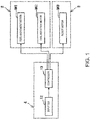
- Fig. 1 is a functional block diagram of a friction spot joining device 1 (hereinafter, referred to as "the joining device 1") according to one embodiment.
- Fig. 2 is a side view of a joining unit 2 provided to the joining device 1 of Fig. 1 .
- the joining device 1 includes the joining unit 2, an articulated robot 3, and a control device 4.
- the joining unit 2 has a frame part 5, a unit main body part 6, and a backing part 7.
- the frame part 5 has an appeared shape of a "C" character or an inverted “C” character in the side view as one example.
- the frame part 5 is connected with the unit main body part 6 and the backing part 7, and is supported by the articulated robot 3.
- the unit main body part 6 has a rotary shaft part 9, a tool 11, a tool-movement motor M1 (advance-retreat drive), and a tool-rotation motor M2 (rotation drive).
- the rotary shaft part 9 extends toward the backing part 7 from a casing of the unit main body part 6, and is provided so as to be approachable to and separatable from the backing part 7.
- a holder is provided at one end of the rotary shaft part 9 in axial directions, which is located away from the casing of the unit main body part 6, and it holds the tool 11 so as to be attachable and detachable.
- the tool 11 has a tool main body part 11a, a pin part 11b, and a shoulder part 11c, and is provided so as to be contactable to or separatable from a surface of a plate W2 opposite from a plate W1.
- the pin part 11b protrudes toward the backing part 7 from the tool main body part 11a, and is surrounded by the shoulder part 11c.
- the circumferential surface of the pin part 11b is flat as one example, it may be threaded.
- the motors M1 and M2 are built in the casing of the unit main body part 6.
- the rotary shaft part 9 and the tool 11 advance and retreat toward the plates W1 and W2 in the axial directions of the rotary shaft part 9.
- the rotary shaft part 9 and the tool 11 rotate on the axis of the rotary shaft part 9.
- Each drive of each of the motors M1 and M2 is controlled by the control device 4.
- the backing part 7 is arranged so as to oppose to the tool 11, while having the plates W1 and W2 therebetween, has a cylindrical appeared shape extending toward the unit main body part 6 from the frame part 5 as one example, and supports the plate W1 from below.
- the articulated robot 3 has a robot motor M3, and moves the joining unit 2 to a given position. Drive of the robot motor M3 is controlled by the control device 4.
- the robot motor M3 may include a plurality of motors.
- the control device 4 is a computer provided with a CPU, a ROM, a RAM, etc., and controls each operation of the joining unit 2 and the articulated robot 3.
- the control device 4 has an inputter 12 and a controller 13.
- the inputter 12 receives information which an operator inputs.
- the ROM stores a given control program.
- the RAM is configured to be storable of setting information inputted through the inputter 12.
- the setting information includes, for example, information on each plate thickness value of the plates W1 and W2, and information on each joining position of the plates W1 and W2.
- the controller 13 controls each of the motors M1-M3 based on the control program. Moreover, based on the control program, the controller 13 calculates an integrated value P as will be described later, and performs a determination of whether the integrated value P reaches a target value P Target , etc.
- FIG. 3 is an operational flowchart of the joining device 1 of Fig. 1 . As illustrated in Fig.
- Step S1 a process for positioning the joining device 1 and the plates W1 and W2 (Step S1), a process for pressing the tool 11 against the plates W1 and W2 (Step S2), a process for the controller 13 determining whether a current value reaches a threshold I 0 (Step S3), a process for the controller 13 starting a calculation of the integrated value P during a joining control (Step S4), a process for the controller 13 determining whether the integrated value P during the joining control reaches the target value P Target (Step S5), a process for separating the tool 11 from the plates W1 and W2 (Step S6), and a process for the controller 13 determining whether the spot joining is completed at all the joining positions (Step S7), are performed in this order, and if there is any remaining position to be joined in the plates W1 and W2, Step S1 is performed again.
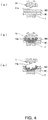
- Figs. 4(a) to (c) are cross-sectional views illustrating each process of the friction spot joining by using the joining device 1 of Fig. 1 .
- Fig. 5 is a view illustrating time changes in the rotational speed of the tool 11 and the current value of the tool-rotation motor M2.
- the time change of the rotational speed of the tool 11 is illustrated by a curve L1
- the time change of the current value of the tool-rotation motor M2 is illustrated by a curve L2.
- the rotational speed of the tool 11 from the contact of the tool 11 with the plate W2 (time t1) to the completion of the joining control (time t3) is initially set so as to be a substantially constant value, but it is not limited to this setting.
- the material of the plates W1 and W2 may be material other than steel (e.g., aluminum etc.).
- the number of plates to be joined may not be limited to only two plates, but may be three or more plates.
- the operator inputs the setting information into the joining device 1 through the inputter 12 so that a given jig holds the plates W1 and W2 in an overlapped manner.
- the controller 13 moves the joining unit 2 to a position corresponding to one joining position, and causes the tip end part of the backing part 7 to support the plate W1 so that the tool 11 is arranged at the plate W2 side and the backing part 7 is arranged at the plate W1 side (Step S1).
- the controller 13 causes the tool 11 to give pressure to the plates W1 and W2 while the tool 11 is rotated so that the joining control in which the tool 11 is pushed into the plates W1 and W2 to carry out the friction stirring is executed.
- the controller 13 controls the tool-rotation motor M2 to start the rotation of the tool 11 at the time t0.
- the controller 13 controls the respective motors M1 and M2 to start the joining control by contacting the tool 11 under rotation with the plate W2 and causing the tip end part of the pin part 11b to give pressure to the plates W1 and W2 at the time t1 (Step S2).
- the pin part 11b is pushed into the plates W1 and W2, and the tool 11 gives pressure to the plates W1 and W2 while being rotated, frictional heat is generated between the tool 11 and the plates W1 and W2 so that the heat is inputted into the plates W1 and W2 from the tool 11.
- the joining process in which the tool 11 is pushed into the plates W1 and W2 is carried out by the tool-rotation motor M2 causing the tool 11 to rotate and the tool 11 giving pressure to the plates W1 and W2, to perform the friction spot joining of the plates W1 and W2.
- the controller 13 determines whether current value required for rotating a rotary shaft of the tool-rotation motor M2 (hereinafter, simply referred to as "the current value of the tool-rotation motor M2") reaches a threshold I 0 (Step S3).
- the threshold I 0 is set beforehand to correspond to a current value of the tool-rotation motor M2 when the pin part 11b is pushed into the plates W1 and W2 (time t2).
- Step S3 if the controller 13 determines that the current value of the tool-rotation motor M2 reaches the threshold I 0 , it starts a calculation of the integrated value P using the current value of the tool-rotation motor M2 during the joining control and a driving period of time of the tool-rotation motor M2 during the joining control (Step S4).
- the integrated value calculating process for the controller 13 calculating the integrated value P during the joining control is performed.
- the integrated value P is calculated using a product of the current value of the tool-rotation motor M2 during the joining control, the driving period of time of the tool-rotation motor M2 during the joining control, and the rotational speed of the tool 11 during the joining control.
- the constant value I N is set to the threshold I 0 .
- the product of the current value difference I D and the driving period of time ⁇ T is expressed by an area S defined by a curve L2 within a range where the current value of the tool-rotation motor M2 exceeds the threshold I 0
- the constant value I N may be other than the threshold I 0 , or may be 0.
- the integrated value P increases with the quantity of heat supplied from the tool 11 and inputted into the plates W1 and W2 during the joining control.
- an encoder which detects a rotational speed of the tool-movement motor M1 may be provided to the joining device 1, and the controller 13 may acquire positional information on the tool 11 by the rotational speed of the tool-movement motor M1.
- the controller 13 determines whether the encoder detects the positional information on the tool 11 when the tool 11 begins to be pushed into the plate W2 during the joining control. If it determines that the positional information is detected, the integration of the integrated value P may be started at Step S4.
- Step S3 may be omitted, and the controller 13 may calculate the integrated value P as a value of a product of the current value of the tool-rotation motor M2 after the contact of the tool 11 with the plate W2, the driving period of time of the tool-rotation motor M2 after the contact, and the rotational speed of the tool 11 after the contact.
- a load detector which detects a pressing force of the tool 11 may be provided to the backing part 7, etc., and the controller 13 may be capable of detecting a timing of the tool 11 contacting the plate W2 by inputting an output signal of the load detector into the controller 13.
- the controller 13 determines whether the integrated value P during the joining control reaches the target value P Target (Step S5). At Step S5, if the controller 13 determines that the integrated value P reaches the target value P Target (see the time t3), it ends the joining control, and as illustrated in Fig. 4(c) , it controls the motor M1 to perform a separation control in which the tool 11 is separated from the plates W1 and W2 (Step S6). Thus, the separating process is performed.
- the target value P Target may be set suitably.
- the threshold I 0 of the current of the tool-rotation motor M2 during the joining control, the rotational speed of the tool 11 during the joining control, and the pressing force of the tool 11 during the joining control are set according to the material of the surface of the tool 11, various characteristics of the surface and the inside of the tool 11 (a frictional coefficient, a heat conductivity, etc.), the dimension and the shape of the tool 11, the materials and the dimensions of the plates W1 and W2, etc.
- the target value P Target is desirable to be set by carrying out initial settings of the threshold I 0 of the current of the tool-rotation motor M2 with which the plates W1 and W2 are suitably spot joined by the tool 11, the rotational speed of the tool 11, and the pressing force of the tool 11.
- the final destination position of the tool 11 with respect to the plates W1 and W2 in each plate thickness direction of the plates W1 and W2 may be initial set, and the target value P Target may be set using the load detector by calculating a value of a product of the current value of the tool-rotation motor M2, the driving period of time of the tool-rotation motor M2, and the rotational speed of the tool 11 after the tool 11 contacts the plate W2 until it reaches the final destination position.
- an external control device communicatably connected with the control device 4 wiredly or wirelessly may integrate the integrated value P.
- the external control device may determine whether the integrated value P during the joining control reaches the target value P Target . In this case, at Step S5, if the external control device determines that the integrated value P during the joining control reaches the target value P Target , it causes the controller 13 to execute the separation control.
- Step S7 determines whether the spot joining of the plates W1 and W2 is completed at all the joining positions.
- Step S7 if the controller 13 determines that the spot joining has not been completed at all the joining positions of the plates W1 and W2, Step S1 is again performed by the controller 13 controlling the robot motor M3 so that the tool 11 moves to the next joining position.
- Step S7 if the controller 13 determines that the spot joining at all the joining positions of the plates W1 and W2 is completed, the operational flow illustrated in Fig. 3 is ended.
- the inputted quantity of heat supplied to the plates W1 and W2 from the tool 11 is uniformized during a period after the tool 11 begins pressing the plates W1 and W2 or the tool 11 begins pushing into the plates W1 and W2 at each joining position until the tool 11 is separated from the plates W1 and W2, a variation of the degree of friction stirring of the plates W1 and W2 carried out by the tool 11 is reduced.
- the pushing period of time of the tool 11 into the plates W1 and W2 and/or the stirring state of the plates W1 and W2 by the tool 11 change to cause the variation in joining quality (e.g., an appearance quality of the joining part of the plates W1 and W2, a plate thickness at a portion which remains inside a pin hole formed at each joining position of the plates W1 and W2 (hereinafter, referred to as "the remaining plate thickness"), joining strength, etc.), or the tool 11 is excessively worn out by the overheating of the tool 11 to shorten the life of the tool 11. Therefore, the joining quality can be stabilized and the life of the tool 11 can be extended, while reducing the burden of the operator to adjust the joining device 1 in order to prevent the variation in the joining quality and/or the shortening of the life of the tool 11.
- the joining quality can be stabilized and the life of the tool 11 can be extended, while reducing the burden of the operator to adjust the joining device 1 in order to prevent the variation in the joining quality and/or the shortening of the life of
- the variation in the degree of the friction stirring the plates W1 and W2 carried out by the tool 11 is reduced, for example, even when carrying out the friction stirring joining of the plates W1 and W2 successively at the plurality of joining positions, it can prevent that the tool 11 which is heated to high temperature and became easy to be pushed into the plates W1 and W2 are excessively pushed into the plates W1 and W2 at the next joining position, the joining quality can be stabilized by reducing the variation in the joining quality, and the life of the tool 11 can be extended by preventing the worn-out of the tool 11 due to the overheat.
- the joining process may be ended even if suitable friction stirring and joining has not been performed by the tool 11.
- the final destination position of the pin part 11b pushed into the plates W1 and W2 is initially set to a constant value with respect to the plates W1 and W2 beforehand and the joining process is ended when the controller simply determines that the pin part 11b reaches the final destination position, the joining process may be ended, for example, even if the suitable friction stirring and joining have not been performed due to the worn-out and damage of the pin part 11b.
- the threshold I 0 of the current value of the motor M2 is set beforehand corresponding to the current value when the pin part 11b is pushed into the plates W1 and W2, and the controller 13 determines whether the integrated value P during the joining control reaches the target value P Target .
- the plates W1 and W2 are suitably friction stirred by the tool 11 with torque of the tool-rotation motor M2 above a specified value, and the joining quality can be managed while joining the plates W1 and W2.
- the driving period of time of the tool-rotation motor M2 during the joining control is shortened to uniformize the inputted quantity of heat supplied to the plates W1 and W2 from the tool 11 at each joining position, the overheat of the tool 11 can be reduced.
- the encoder may be provided to the joining device 1, and at each joining position, the controller 13 may further control the tool-movement motor M1 so that the rotational speed of the tool-movement motor M1 when the tool 11 is pressed against the plates W1 and W2 and the tool 11 is pushed into the plates W1 and W2 becomes constant during the joining control.
- the remaining plate thickness at each joining position of the plates W1 and W2 can further be uniformized to improve the joining quality of the plates W1 and W2.
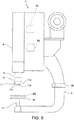
- Fig. 6 is a side view of a joining unit 2 provided to a joining device 1 of one modification.
- the joining device 1 of this modification is provided with a thermometer 30 which is capable of measuring temperature of the tool 11 (here, a surface temperature near the tip end part of the pin part 11b).
- the thermometer 30 is a radiation thermometer as one example, and is fixed to the frame part 5 of the joining unit 2. Measurements of the thermometer 30 are monitored by the controller 13.
- the controller 13 changes the target value P Target according to the temperature of the tool 11 pushed into the plates W1 and W2 during the joining control. Concretely, the controller 13 changes the target value P Target according to the surface temperature of the pin part 11b which is measured by the thermometer 30 immediately before pushing the tool 11 into the plates W1 and W2 during the joining control at each joining position.
- the controller 13 sets the target value P Target to a smaller value than the original setting (e.g., a value within a range of 70% to 90% of the original setting), and if it is lower than a threshold T 2 , the controller 13 sets the target value P Target to a larger value than the original setting (e.g., a value within a range of 110% to 130% of the original setting).
- the thresholds T 1 and T 2 can be set suitably.
- the threshold T 1 can be set to, for example, the surface temperature of the pin part 11b when the remaining plate thickness of the plates W1 and W2 becomes below a given first plate thickness value
- the threshold T 2 can be set to, for example, the surface temperature of the pin part 11b when the remaining plate thickness of the plates W1 and W2 exceeds a given second plate thickness value.
- the temperature of the tool 11 during and after the joining can further be stabilized even if the temperature of the tool 11 immediately before pushing the tool 11 into the plates W1 and W2 at each joining position differs.
- the integrated value P is calculated as a value of a product of the current value of the tool-rotation motor M2 during the joining control and the driving period of time of the tool-rotation motor M2 during the joining control.
- the integrated value P can be expressed by the area S of Fig. 5 .
- the joining device 1 of this modification can favorably be used, for example, in a case where the rotational speed N of the tool 11 is comparatively difficult to affect to the change in the inputted quantity of heat supplied to the plates W1 and W2 from the tool 11, such as when the rotational speed N during the joining control is set to a constant value.
- the threshold I 0 of the current of the tool-rotation motor M2, the rotational speed of the tool 11, and the pressing force of the tool 11 were initially set so that the spot joining of the plates W1 and W2 is suitably carried out by the tool 11 of which the pin part 11b is formed with the covering part.
- the integrated value P and the target value P Target were set to a value of a product of the current value of the tool-rotation motor M2 after the threshold I 0 being reached and the driving period of time of the tool-rotation motor M2 after the current value reaches the threshold I 0 .
- the joining device of the comparative example using a tool 11 similar to the example, like the example, the rotational speed of the tool 11, the pressing force of the tool 11, and a time after the pressing of the tool 11 against the plates W1 and W2 is started until the tool 11 is separated from the plates W1 and W2 (hereinafter, referred to as "the joining period of time") were initially set.
- the joining strength of the plates W1 and W2 were measured by a tensile shear strength test defined in the JIS Z 3140 standard.
- the temperature of the tool 11 was measured by the radiation thermometer.
- Fig. 7 is a view illustrating changes in the temperature of the tool 11 and the diameter of the pin part 11b of the comparative example.
- Fig. 8 is a view illustrating changes in the joining strength and the remaining plate thickness of the comparative example.
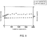
- each value of the temperature of the tool 11, the diameter of the pin part 11b, the joining strength of the plates W1 and W2, and the remaining plate thickness of the plates W1 and W2 at each joining position is illustrated by a relative value.
- the friction spot joining was carried out during the same joining period of time at each joining position, regardless of the state of the tool 11 being changed. Specifically, between the beginning of the test and around when the number of joining spots exceeds 100, a thermal expansion by the overheat of the tool 11, a break-in of the tool 11, and an increase in the frictional coefficient of the tool 11 progress, and thereafter, before the number of joining spots becomes 1,000, the decrease in the frictional coefficient of the tool 11 progresses, and from around when the number of joining spots exceeds 1,000, the covering part formed in the pin part 11b exfoliates and the wear of the pin part 11b progresses, leading to the pin part 11b becoming easier to be pushed into the plates W1 and W2.
- Fig. 9 is a view illustrating changes in the temperature of the tool 11 and the diameter of the pin part 11b of the example.
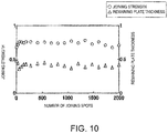
- Fig. 10 is a view illustrating changes in the joining strength and the remaining plate thickness of the example.
- Figs. 9 and 10 similar to Figs. 7 and 8 , changes in the temperature of the tool 11, the diameter of the pin part 11b, the joining strength of the plates W1 and W2, and the remaining plate thickness of the plates W1 and W2 are illustrated.
- Figs. 9 and 10 in this example, it is confirmed that any of the temperature of the tool 11, the diameter of the pin part 11b, the joining strength, and the remaining plate thickness is more stable than that of the comparative example within the test range.
Landscapes
- Engineering & Computer Science (AREA)
- Mechanical Engineering (AREA)
- Pressure Welding/Diffusion-Bonding (AREA)
Abstract
Description
- The present disclosure relates to a friction spot joining device and a friction spot joining method.
- Conventionally, a friction spot joining method is known as a method of mutually joining a pair of plates. When joining the pair of plates by this method, a tool of a friction spot joining device is pushed into the pair of plates which are overlapped with each other while the tool is rotated, and is drawn out after the completion of joining, for example, as disclosed in
Patent Document 1. Thus, the pair of plates are friction-spot joined. - [Patent Document 1]
JP3,471,338B2 - Meanwhile, when carrying out the friction spot joining of the pair of plates, if the surface condition of the tool changes with an increase in the number of joining points or the frictional coefficient between the tool and the plates changes due to different surface conditions of the plates at respective joining positions, a pushing period of time of the tool to the plates and a stirring state of the plates by the tool may change to cause a variation in the joining quality, or the tool may be overheated to cause an excessive worn-out and a shortened life of the tool.
- Therefore, one purpose of the present disclosure is, when carrying out the friction spot joining of a pair of plates, to stabilize a joining quality and extend the life of a tool, while reducing an operator's burden to adjust a joining device, by controlling a variation in the joining quality and an overheat of the tool even if states of the tool and/or the plates change.
- In order to solve the above problem, according to one aspect of the present disclosure, a friction spot joining device configured to carry out friction spot joining of a pair of plates is provided, which includes an advance-retreat drive configured to advance and retreat a tool to/from the plates, a rotation drive configured to rotate the tool, and a controller configured to control the advance-retreat drive and the rotation drive. The controller executes a joining control in which the tool is caused to give pressure to the plates while the tool is rotated so that the tool is pushed into the plates, and a separating control in which the tool is separated from the plates when an integrated value calculated using a current value of the rotation drive during the joining control and a driving period of time during the joining control is determined to be reached a target value.
- According to this configuration, since the tool is separated from the plates when the integrated value calculated using the current value and the driving time period is determined to be reached the target value, the inputted quantity of heat supplied to the plates from the tool is uniformized during a period after the tool begins pressing the plates and pushing into the plates at each joining position until the tool is separated from the plates, a variation of the degree of friction stirring of the plates carried out by the tool is reduced. Thus, even if the states of the tool or the plates change when carrying out the friction spot joining of the plates, it can prevent that the pushing period of time of the tool into the plates and/or the stirring state of the plates by the tool change to cause the variation in a joining quality, or the tool is excessively worn out by an overheating of the tool to shorten the life of the tool. Therefore, the joining quality can be stabilized and the life of the tool can be extended, while reducing the burden of an operator to adjust the joining device in order to reduce such a variation in the joining quality and/or the overheat of the tool.
- The controller may calculate the integrated value using a product of the current value, the driving period of time, and a rotational speed of the tool during the joining control. Thus, for example, when the rotational speed of the tool during the joining control is increased, the driving period of time is shortened to uniformize the inputted quantity of heat supplied to the plates from the tool at each joining position, and the overheat of the tool is reduced.
- The controller may change the target value according to temperature of the tool pushed into the plates during the joining control. Thus, even if the temperature of the tool pushed into the plates at each joining position differs, by changing the target value accordingly, the temperature of the tool during and after the joining can further be stabilized.
- According to another aspect of the present disclosure, a method of carrying out friction spot joining of a pair of plates is provided, which includes a joining process for causing a tool to give pressure to the plates while the tool is rotated by a rotation drive so that the tool is pushed into the plates, an integrated value calculating process for calculating an integrated value using a current value of the rotation drive in the joining process and a driving period of time of the rotation drive in the joining process, and a separating process for separating the tool from the plates when the integrated value is determined to be reached a target value.
- According to the present disclosure, when carrying out the friction spot joining of the pair of plates, even if the states of the tool and/or the plates change, the joining quality is stabilized and the life of the tool is extended while reducing the operator's burden to adjust the joining device, by controlling the variation in the joining quality and the overheat of the tool.
-
-
Fig. 1 is a functional block diagram of a friction spot joining device according to one embodiment. -
Fig. 2 is a side view of a joining unit provided to the friction spot joining device ofFig. 1 . -
Fig. 3 is an operational flowchart of the friction spot joining device ofFig. 1 . -
Figs. 4(a) to (c) are cross-sectional views illustrating each process of friction spot joining by using the friction spot joining device ofFig. 1 . -
Fig. 5 is a view illustrating time changes of a rotational speed of a tool and a current value of a tool-rotation motor. -
Fig. 6 is a side view of a joining unit provided to a friction spot joining device of a modification. -
Fig. 7 is a view illustrating changes in temperature of a tool and a diameter of a pin part of a comparative example. -
Fig. 8 is a view illustrating changes in a joining strength and a remaining plate thickness of the comparative example. -
Fig. 9 is a view illustrating changes in temperature of the tool and a diameter of the pin part of one example. -
Fig. 10 is a view illustrating changes in the joining strength and a remaining plate thickness of the example. - Hereinafter, one embodiment is described with reference to the drawings.
-
Fig. 1 is a functional block diagram of a friction spot joining device 1 (hereinafter, referred to as "the joiningdevice 1") according to one embodiment.Fig. 2 is a side view of a joiningunit 2 provided to the joiningdevice 1 ofFig. 1 . As illustrated inFigs. 1 and2 , the joiningdevice 1 includes the joiningunit 2, an articulatedrobot 3, and acontrol device 4. The joiningunit 2 has aframe part 5, a unitmain body part 6, and abacking part 7. - The
frame part 5 has an appeared shape of a "C" character or an inverted "C" character in the side view as one example. Theframe part 5 is connected with the unitmain body part 6 and thebacking part 7, and is supported by the articulatedrobot 3. The unitmain body part 6 has arotary shaft part 9, atool 11, a tool-movement motor M1 (advance-retreat drive), and a tool-rotation motor M2 (rotation drive). Therotary shaft part 9 extends toward thebacking part 7 from a casing of the unitmain body part 6, and is provided so as to be approachable to and separatable from thebacking part 7. A holder is provided at one end of therotary shaft part 9 in axial directions, which is located away from the casing of the unitmain body part 6, and it holds thetool 11 so as to be attachable and detachable. - The
tool 11 has a toolmain body part 11a, apin part 11b, and ashoulder part 11c, and is provided so as to be contactable to or separatable from a surface of a plate W2 opposite from a plate W1. Thepin part 11b protrudes toward thebacking part 7 from the toolmain body part 11a, and is surrounded by theshoulder part 11c. Although the circumferential surface of thepin part 11b is flat as one example, it may be threaded. - The motors M1 and M2 are built in the casing of the unit
main body part 6. When the tool-movement motor M1 is driven, therotary shaft part 9 and thetool 11 advance and retreat toward the plates W1 and W2 in the axial directions of therotary shaft part 9. Moreover, when the tool-rotation motor M2 is driven, therotary shaft part 9 and thetool 11 rotate on the axis of therotary shaft part 9. Each drive of each of the motors M1 and M2 is controlled by thecontrol device 4. - The
backing part 7 is arranged so as to oppose to thetool 11, while having the plates W1 and W2 therebetween, has a cylindrical appeared shape extending toward the unitmain body part 6 from theframe part 5 as one example, and supports the plate W1 from below. A tip end part of one end of thebacking part 7 in the axial directions, which is located away from theframe part 5, contacts a surface of the plate W1 opposite from the plate W2. - The articulated
robot 3 has a robot motor M3, and moves the joiningunit 2 to a given position. Drive of the robot motor M3 is controlled by thecontrol device 4. The robot motor M3 may include a plurality of motors. - The
control device 4 is a computer provided with a CPU, a ROM, a RAM, etc., and controls each operation of the joiningunit 2 and the articulatedrobot 3. Thecontrol device 4 has aninputter 12 and acontroller 13. Theinputter 12 receives information which an operator inputs. The ROM stores a given control program. The RAM is configured to be storable of setting information inputted through theinputter 12. The setting information includes, for example, information on each plate thickness value of the plates W1 and W2, and information on each joining position of the plates W1 and W2. - The
controller 13 controls each of the motors M1-M3 based on the control program. Moreover, based on the control program, thecontroller 13 calculates an integrated value P as will be described later, and performs a determination of whether the integrated value P reaches a target value PTarget, etc. - Next, a method of successively carrying out the friction spot joining of the plates W1 and W2 made of steel at a plurality of joining positions by using the joining
device 1 is illustrated.Fig. 3 is an operational flowchart of the joiningdevice 1 ofFig. 1 . As illustrated inFig. 3 , a process for positioning the joiningdevice 1 and the plates W1 and W2 (Step S1), a process for pressing thetool 11 against the plates W1 and W2 (Step S2), a process for thecontroller 13 determining whether a current value reaches a threshold I0 (Step S3), a process for thecontroller 13 starting a calculation of the integrated value P during a joining control (Step S4), a process for thecontroller 13 determining whether the integrated value P during the joining control reaches the target value PTarget (Step S5), a process for separating thetool 11 from the plates W1 and W2 (Step S6), and a process for thecontroller 13 determining whether the spot joining is completed at all the joining positions (Step S7), are performed in this order, and if there is any remaining position to be joined in the plates W1 and W2, Step S1 is performed again. -
Figs. 4(a) to (c) are cross-sectional views illustrating each process of the friction spot joining by using the joiningdevice 1 ofFig. 1 .Fig. 5 is a view illustrating time changes in the rotational speed of thetool 11 and the current value of the tool-rotation motor M2. InFig. 5 , the time change of the rotational speed of thetool 11 is illustrated by a curve L1, and the time change of the current value of the tool-rotation motor M2 is illustrated by a curve L2. As illustrated by the curve L1, the rotational speed of thetool 11 from the contact of thetool 11 with the plate W2 (time t1) to the completion of the joining control (time t3) is initially set so as to be a substantially constant value, but it is not limited to this setting. Moreover, the material of the plates W1 and W2 may be material other than steel (e.g., aluminum etc.). Moreover, the number of plates to be joined may not be limited to only two plates, but may be three or more plates. - First, the operator inputs the setting information into the joining
device 1 through theinputter 12 so that a given jig holds the plates W1 and W2 in an overlapped manner. Then, as illustrated inFig. 4(a) , thecontroller 13 moves the joiningunit 2 to a position corresponding to one joining position, and causes the tip end part of thebacking part 7 to support the plate W1 so that thetool 11 is arranged at the plate W2 side and thebacking part 7 is arranged at the plate W1 side (Step S1). - Next, as illustrated in
Fig. 4(b) , by controlling the respective motors M1 and M2, thecontroller 13 causes thetool 11 to give pressure to the plates W1 and W2 while thetool 11 is rotated so that the joining control in which thetool 11 is pushed into the plates W1 and W2 to carry out the friction stirring is executed. As illustrated inFig. 5 , here, thecontroller 13 controls the tool-rotation motor M2 to start the rotation of thetool 11 at the time t0. Moreover, thecontroller 13 controls the respective motors M1 and M2 to start the joining control by contacting thetool 11 under rotation with the plate W2 and causing the tip end part of thepin part 11b to give pressure to the plates W1 and W2 at the time t1 (Step S2). At the time t2, thepin part 11b is pushed into the plates W1 and W2, and thetool 11 gives pressure to the plates W1 and W2 while being rotated, frictional heat is generated between thetool 11 and the plates W1 and W2 so that the heat is inputted into the plates W1 and W2 from thetool 11. Thus, the joining process in which thetool 11 is pushed into the plates W1 and W2 is carried out by the tool-rotation motor M2 causing thetool 11 to rotate and thetool 11 giving pressure to the plates W1 and W2, to perform the friction spot joining of the plates W1 and W2. - The
controller 13 determines whether current value required for rotating a rotary shaft of the tool-rotation motor M2 (hereinafter, simply referred to as "the current value of the tool-rotation motor M2") reaches a threshold I0 (Step S3). Here, the threshold I0 is set beforehand to correspond to a current value of the tool-rotation motor M2 when thepin part 11b is pushed into the plates W1 and W2 (time t2). At Step S3, if thecontroller 13 determines that the current value of the tool-rotation motor M2 reaches the threshold I0, it starts a calculation of the integrated value P using the current value of the tool-rotation motor M2 during the joining control and a driving period of time of the tool-rotation motor M2 during the joining control (Step S4). Thus, the integrated value calculating process for thecontroller 13 calculating the integrated value P during the joining control is performed. - As one example, the integrated value P is calculated using a product of the current value of the tool-rotation motor M2 during the joining control, the driving period of time of the tool-rotation motor M2 during the joining control, and the rotational speed of the
tool 11 during the joining control. Here, the integrated value P is calculated as a value of the product of a current value difference ID obtained by subtracting a constant value IN from the current value IM of the tool-rotation motor M2 after the current value reaches the threshold I0 (IM-IN=ID), the driving period of time ΔT of the tool-rotation motor M2 after the current value I reaches the threshold I0, and the rotational speed N of thetool 11 after the current value I reaches the threshold I0 (ID×ΔT×N=P). Here, the constant value IN is set to the threshold I0. - As illustrated in
Fig. 5 , in this case, in the graph representing a relation between the current value of the tool-rotation motor M2 and a lapsed time of the joining control (driving period of time), the product of the current value difference ID and the driving period of time ΔT is expressed by an area S defined by a curve L2 within a range where the current value of the tool-rotation motor M2 exceeds the threshold I0, and the integrated value P is expressed by a value of a product of the area S and the rotational speed N (S×N=P). Note that, the constant value IN may be other than the threshold I0, or may be 0. The integrated value P increases with the quantity of heat supplied from thetool 11 and inputted into the plates W1 and W2 during the joining control. - Moreover, an encoder which detects a rotational speed of the tool-movement motor M1 may be provided to the joining
device 1, and thecontroller 13 may acquire positional information on thetool 11 by the rotational speed of the tool-movement motor M1. In this case, at Step S3, thecontroller 13 determines whether the encoder detects the positional information on thetool 11 when thetool 11 begins to be pushed into the plate W2 during the joining control. If it determines that the positional information is detected, the integration of the integrated value P may be started at Step S4. - Moreover, Step S3 may be omitted, and the
controller 13 may calculate the integrated value P as a value of a product of the current value of the tool-rotation motor M2 after the contact of thetool 11 with the plate W2, the driving period of time of the tool-rotation motor M2 after the contact, and the rotational speed of thetool 11 after the contact. In this case, for example, a load detector which detects a pressing force of thetool 11 may be provided to thebacking part 7, etc., and thecontroller 13 may be capable of detecting a timing of thetool 11 contacting the plate W2 by inputting an output signal of the load detector into thecontroller 13. - The
controller 13 determines whether the integrated value P during the joining control reaches the target value PTarget (Step S5). At Step S5, if thecontroller 13 determines that the integrated value P reaches the target value PTarget (see the time t3), it ends the joining control, and as illustrated inFig. 4(c) , it controls the motor M1 to perform a separation control in which thetool 11 is separated from the plates W1 and W2 (Step S6). Thus, the separating process is performed. - The target value PTarget may be set suitably. The threshold I0 of the current of the tool-rotation motor M2 during the joining control, the rotational speed of the
tool 11 during the joining control, and the pressing force of thetool 11 during the joining control are set according to the material of the surface of thetool 11, various characteristics of the surface and the inside of the tool 11 (a frictional coefficient, a heat conductivity, etc.), the dimension and the shape of thetool 11, the materials and the dimensions of the plates W1 and W2, etc. Therefore, for example, by a prior experiment, the target value PTarget is desirable to be set by carrying out initial settings of the threshold I0 of the current of the tool-rotation motor M2 with which the plates W1 and W2 are suitably spot joined by thetool 11, the rotational speed of thetool 11, and the pressing force of thetool 11. - Note that the final destination position of the
tool 11 with respect to the plates W1 and W2 in each plate thickness direction of the plates W1 and W2 may be initial set, and the target value PTarget may be set using the load detector by calculating a value of a product of the current value of the tool-rotation motor M2, the driving period of time of the tool-rotation motor M2, and the rotational speed of thetool 11 after thetool 11 contacts the plate W2 until it reaches the final destination position. - Moreover, for example, an external control device communicatably connected with the
control device 4 wiredly or wirelessly may integrate the integrated value P. Moreover, at Step S5, for example, the external control device may determine whether the integrated value P during the joining control reaches the target value PTarget. In this case, at Step S5, if the external control device determines that the integrated value P during the joining control reaches the target value PTarget, it causes thecontroller 13 to execute the separation control. - When the separation control is completed at one of the joining positions, the
controller 13 determines whether the spot joining of the plates W1 and W2 is completed at all the joining positions (Step S7). At Step S7, if thecontroller 13 determines that the spot joining has not been completed at all the joining positions of the plates W1 and W2, Step S1 is again performed by thecontroller 13 controlling the robot motor M3 so that thetool 11 moves to the next joining position. At Step S7, if thecontroller 13 determines that the spot joining at all the joining positions of the plates W1 and W2 is completed, the operational flow illustrated inFig. 3 is ended. - As described above, since in the joining
device 1 thetool 11 is separated from the plates W1 and W2 when the integrated value P during the joining control is determined to be reached the target value PTarget, the inputted quantity of heat supplied to the plates W1 and W2 from thetool 11 is uniformized during a period after thetool 11 begins pressing the plates W1 and W2 or thetool 11 begins pushing into the plates W1 and W2 at each joining position until thetool 11 is separated from the plates W1 and W2, a variation of the degree of friction stirring of the plates W1 and W2 carried out by thetool 11 is reduced. Thus, when carrying out the friction spot joining of the plates W1 and W2, it can prevent that, due to the change in the surface condition of thetool 11 and/or change in the frictional coefficient between thetool 11 and the plates W1 and W2, the pushing period of time of thetool 11 into the plates W1 and W2 and/or the stirring state of the plates W1 and W2 by thetool 11 change to cause the variation in joining quality (e.g., an appearance quality of the joining part of the plates W1 and W2, a plate thickness at a portion which remains inside a pin hole formed at each joining position of the plates W1 and W2 (hereinafter, referred to as "the remaining plate thickness"), joining strength, etc.), or thetool 11 is excessively worn out by the overheating of thetool 11 to shorten the life of thetool 11. Therefore, the joining quality can be stabilized and the life of thetool 11 can be extended, while reducing the burden of the operator to adjust the joiningdevice 1 in order to prevent the variation in the joining quality and/or the shortening of the life of thetool 11. - Moreover, since the variation in the degree of the friction stirring the plates W1 and W2 carried out by the
tool 11 is reduced, for example, even when carrying out the friction stirring joining of the plates W1 and W2 successively at the plurality of joining positions, it can prevent that thetool 11 which is heated to high temperature and became easy to be pushed into the plates W1 and W2 are excessively pushed into the plates W1 and W2 at the next joining position, the joining quality can be stabilized by reducing the variation in the joining quality, and the life of thetool 11 can be extended by preventing the worn-out of thetool 11 due to the overheat. - Here, if the period of time for the
tool 11 to carry out the friction stirring and joining of the plates W1 and W2 is initially set to a constant value beforehand and the joining process is ended when the controller simply determines that the period of time is passed, the joining process may be ended even if suitable friction stirring and joining has not been performed by thetool 11. Moreover, if the final destination position of thepin part 11b pushed into the plates W1 and W2 is initially set to a constant value with respect to the plates W1 and W2 beforehand and the joining process is ended when the controller simply determines that thepin part 11b reaches the final destination position, the joining process may be ended, for example, even if the suitable friction stirring and joining have not been performed due to the worn-out and damage of thepin part 11b. - On the other hand, in the joining
device 1, at each joining position, the threshold I0 of the current value of the motor M2 is set beforehand corresponding to the current value when thepin part 11b is pushed into the plates W1 and W2, and thecontroller 13 determines whether the integrated value P during the joining control reaches the target value PTarget. Thus, it can be confirmed whether the plates W1 and W2 are suitably friction stirred by thetool 11 with torque of the tool-rotation motor M2 above a specified value, and the joining quality can be managed while joining the plates W1 and W2. - Moreover, by calculating the integrated value P using a product with the rotational speed N of the current value of the tool-rotation motor M2 during the joining control, the driving period of time of the tool-rotation motor M2 during the joining control, and the
tool 11 during the joining control. For example, when the rotational speed N of thetool 11 in the joining control is increased, since the driving period of time of the tool-rotation motor M2 during the joining control is shortened to uniformize the inputted quantity of heat supplied to the plates W1 and W2 from thetool 11 at each joining position, the overheat of thetool 11 can be reduced. - Note that, for example, the encoder may be provided to the joining
device 1, and at each joining position, thecontroller 13 may further control the tool-movement motor M1 so that the rotational speed of the tool-movement motor M1 when thetool 11 is pressed against the plates W1 and W2 and thetool 11 is pushed into the plates W1 and W2 becomes constant during the joining control. Thus, the remaining plate thickness at each joining position of the plates W1 and W2 can further be uniformized to improve the joining quality of the plates W1 and W2. - Below, modifications will be described focusing on differences from the embodiment.
-
Fig. 6 is a side view of a joiningunit 2 provided to a joiningdevice 1 of one modification. The joiningdevice 1 of this modification is provided with athermometer 30 which is capable of measuring temperature of the tool 11 (here, a surface temperature near the tip end part of thepin part 11b). Thethermometer 30 is a radiation thermometer as one example, and is fixed to theframe part 5 of the joiningunit 2. Measurements of thethermometer 30 are monitored by thecontroller 13. - In the joining
device 1 of this modification, thecontroller 13 changes the target value PTarget according to the temperature of thetool 11 pushed into the plates W1 and W2 during the joining control. Concretely, thecontroller 13 changes the target value PTarget according to the surface temperature of thepin part 11b which is measured by thethermometer 30 immediately before pushing thetool 11 into the plates W1 and W2 during the joining control at each joining position. Concretely, immediately before pushing thetool 11 into the plates W1 and W2 during the joining control at each joining position, if the surface temperature of thepin part 11b measured by thethermometer 30 is higher than a threshold T1, thecontroller 13 sets the target value PTarget to a smaller value than the original setting (e.g., a value within a range of 70% to 90% of the original setting), and if it is lower than a threshold T2, thecontroller 13 sets the target value PTarget to a larger value than the original setting (e.g., a value within a range of 110% to 130% of the original setting). The thresholds T1 and T2 can be set suitably. By a prior experiment, the threshold T1 can be set to, for example, the surface temperature of thepin part 11b when the remaining plate thickness of the plates W1 and W2 becomes below a given first plate thickness value, and the threshold T2 can be set to, for example, the surface temperature of thepin part 11b when the remaining plate thickness of the plates W1 and W2 exceeds a given second plate thickness value. - Thus, by changing the target value PTarget according to the temperature of the
tool 11 immediately before pushing it into the plates W1 and W2 during the joining control, the temperature of thetool 11 during and after the joining can further be stabilized even if the temperature of thetool 11 immediately before pushing thetool 11 into the plates W1 and W2 at each joining position differs. - In a joining
device 1 of another modification, the integrated value P is calculated as a value of a product of the current value of the tool-rotation motor M2 during the joining control and the driving period of time of the tool-rotation motor M2 during the joining control. As one example, the integrated value P is calculated as a value of a product of the current value difference ID and the driving period of time ΔT (ID×ΔT=P). In this modification, the integrated value P can be expressed by the area S ofFig. 5 . - By calculating the integrated value P as described above, the calculation method of the integrated value P can be simplified and the calculating load of the
controller 13 can be reduced. Especially, the joiningdevice 1 of this modification can favorably be used, for example, in a case where the rotational speed N of thetool 11 is comparatively difficult to affect to the change in the inputted quantity of heat supplied to the plates W1 and W2 from thetool 11, such as when the rotational speed N during the joining control is set to a constant value. - Using a joining device of each of an example and a comparative example, each change in the temperature of the
tool 11, the diameter of the pin part lib, the joining strength of the plates W1 and W2, the remaining plate thickness of the plates W1 and W2 when successively carrying out the friction spot joining of the plates W1 and W2 at the plurality of joining positions, was examined. - In the joining device of the example, the threshold I0 of the current of the tool-rotation motor M2, the rotational speed of the
tool 11, and the pressing force of thetool 11 were initially set so that the spot joining of the plates W1 and W2 is suitably carried out by thetool 11 of which thepin part 11b is formed with the covering part. The integrated value P and the target value PTarget were set to a value of a product of the current value of the tool-rotation motor M2 after the threshold I0 being reached and the driving period of time of the tool-rotation motor M2 after the current value reaches the threshold I0. In the joining device of the comparative example, using atool 11 similar to the example, like the example, the rotational speed of thetool 11, the pressing force of thetool 11, and a time after the pressing of thetool 11 against the plates W1 and W2 is started until thetool 11 is separated from the plates W1 and W2 (hereinafter, referred to as "the joining period of time") were initially set. The joining strength of the plates W1 and W2 were measured by a tensile shear strength test defined in the JIS Z 3140 standard. The temperature of thetool 11 was measured by the radiation thermometer. -
Fig. 7 is a view illustrating changes in the temperature of thetool 11 and the diameter of thepin part 11b of the comparative example.Fig. 8 is a view illustrating changes in the joining strength and the remaining plate thickness of the comparative example. InFigs. 7 and8 , each value of the temperature of thetool 11, the diameter of thepin part 11b, the joining strength of the plates W1 and W2, and the remaining plate thickness of the plates W1 and W2 at each joining position is illustrated by a relative value. - As illustrated in
Figs. 7 and8 , it was confirmed that the temperature of thetool 11 and the joining strength of the plates W1 and W2 of the comparative example increase rapidly between the beginning of the test and around when the number of joining spots exceeds 100, then decrease, and gently increase around when the number of joining spots exceeds 1,000. Moreover, it was confirmed that the diameter of thepin part 11b of the comparative example increases between the beginning of the test and around when the number of joining spots exceeds 100, and then decreases. Moreover, it was confirmed that the remaining plate thickness of the comparative example decreases rapidly between the beginning of the test and around when the number of joining spots exceeds 100, then increases, and decreases from around when the number of joining spots exceeds 1,000. - As one of the reasons such a test result was obtained, it is considered that, in the comparative example, the friction spot joining was carried out during the same joining period of time at each joining position, regardless of the state of the
tool 11 being changed. Specifically, between the beginning of the test and around when the number of joining spots exceeds 100, a thermal expansion by the overheat of thetool 11, a break-in of thetool 11, and an increase in the frictional coefficient of thetool 11 progress, and thereafter, before the number of joining spots becomes 1,000, the decrease in the frictional coefficient of thetool 11 progresses, and from around when the number of joining spots exceeds 1,000, the covering part formed in thepin part 11b exfoliates and the wear of thepin part 11b progresses, leading to thepin part 11b becoming easier to be pushed into the plates W1 and W2. -
Fig. 9 is a view illustrating changes in the temperature of thetool 11 and the diameter of thepin part 11b of the example.Fig. 10 is a view illustrating changes in the joining strength and the remaining plate thickness of the example. InFigs. 9 and10 , similar toFigs. 7 and8 , changes in the temperature of thetool 11, the diameter of thepin part 11b, the joining strength of the plates W1 and W2, and the remaining plate thickness of the plates W1 and W2 are illustrated. As illustrated inFigs. 9 and10 , in this example, it is confirmed that any of the temperature of thetool 11, the diameter of thepin part 11b, the joining strength, and the remaining plate thickness is more stable than that of the comparative example within the test range. - As one of the reasons such a test result was obtained, in this example, it is considered that, even if the thermal expansion, the break-in, the increase in the wear coefficient, etc. of the
tool 11 are caused to some extent after the test are started, since the inputted quantity of heat supplied to the plates W1 and W2 from thetool 11 are uniformized after thetool 11 begins to be pushed into the plates W1 and W2 at each joining position, the variation in the degree of the friction stirring of the plates W1 and W2 by thetool 11 is reduced to stabilize the joining state of the plates W1 and W2, and the temperature of thetool 11 and the remaining plate thickness of the plates W1 and W2 are uniformized. - Moreover, in this example, it is found from the test result that, when successively carrying out the friction spot joining of the plates W1 and W2 at the plurality of joining positions, the time and effort of the operator to adjust the joining device is reduced, the joining quality is stabilized, and the life of the
tool 11 is extended. -
- P
- Integrated Value
- PTarget
- Target Value
- M1
- Tool-movement Motor (Advance-retreat Drive)
- M2
- Tool-rotation Motor (Rotation Drive)
- W1, W2
- Plate
- 1
- Joining Device
- 11
- Tool
- 13
- Controller
Claims (4)
- A friction spot joining device configured to carry out friction spot joining of a pair of plates, comprising:an advance-retreat drive configured to advance and retreat a tool to/from the plates;a rotation drive configured to rotate the tool; anda controller configured to control the advance-retreat drive and the rotation drive,wherein the controller executes:a joining control in which the tool is caused to give pressure to the plates while the tool is rotated so that the tool is pushed into the plates, anda separating control in which the tool is separated from the plates when an integrated value calculated using a current value of the rotation drive during the joining control and a driving period of time during the joining control is determined to be reached a target value.
- The friction spot joining device of claim 1, wherein the controller calculates the integrated value using a product of the current value, the driving period of time, and a rotational speed of the tool during the joining control.
- The friction spot joining device of claim 1 or 2, wherein the controller changes the target value according to temperature of the tool pushed into the plates during the joining control.
- A method of carrying out friction spot joining of a pair of plates, comprising:a joining process for causing a tool to give pressure to the plates while the tool is rotated by a rotation drive so that the tool is pushed into the plates;an integrated value calculating process for calculating an integrated value using a current value of the rotation drive in the joining process and a driving period of time of the rotation drive in the joining process; anda separating process for separating the tool from the plates when the integrated value is determined to be reached a target value.
Applications Claiming Priority (2)
| Application Number | Priority Date | Filing Date | Title |
|---|---|---|---|
| JP2015228691A JP6554029B2 (en) | 2015-11-24 | 2015-11-24 | Friction stir spot welding device and friction stir spot welding method |
| PCT/JP2016/004887 WO2017090239A1 (en) | 2015-11-24 | 2016-11-15 | Friction spot joining device and friction spot joining method |
Publications (3)
| Publication Number | Publication Date |
|---|---|
| EP3381599A1 true EP3381599A1 (en) | 2018-10-03 |
| EP3381599A4 EP3381599A4 (en) | 2019-08-14 |
| EP3381599B1 EP3381599B1 (en) | 2020-09-09 |
Family
ID=58764050
Family Applications (1)
| Application Number | Title | Priority Date | Filing Date |
|---|---|---|---|
| EP16868190.6A Active EP3381599B1 (en) | 2015-11-24 | 2016-11-15 | Friction spot joining device and friction spot joining method |
Country Status (6)
| Country | Link |
|---|---|
| US (1) | US11292076B2 (en) |
| EP (1) | EP3381599B1 (en) |
| JP (1) | JP6554029B2 (en) |
| KR (1) | KR102000691B1 (en) |
| CN (1) | CN108349042B (en) |
| WO (1) | WO2017090239A1 (en) |
Families Citing this family (5)
| Publication number | Priority date | Publication date | Assignee | Title |
|---|---|---|---|---|
| US10583519B2 (en) * | 2016-08-12 | 2020-03-10 | The Boeing Company | Friction stir welding method and assembly |
| US11498154B2 (en) * | 2017-02-21 | 2022-11-15 | Ihi Corporation | Linear friction-joining device and linear friction-joining method |
| JP7181113B2 (en) * | 2019-02-08 | 2022-11-30 | トヨタ自動車株式会社 | Dissimilar metal joining method |
| JP7223651B2 (en) * | 2019-07-01 | 2023-02-16 | 川崎重工業株式会社 | Welding system and its operation method |
| JP6986647B1 (en) * | 2021-03-31 | 2021-12-22 | 株式会社日立パワーソリューションズ | How to insert a robot-type friction stir welding device and its joining tool |
Family Cites Families (40)
| Publication number | Priority date | Publication date | Assignee | Title |
|---|---|---|---|---|
| US6050475A (en) * | 1998-05-29 | 2000-04-18 | Mcdonnell Douglas Corporation | Method and apparatus for controlling downforce during friction stir welding |
| JP4286962B2 (en) * | 1999-04-21 | 2009-07-01 | 昭和電工株式会社 | Friction stir welding method |
| US6236017B1 (en) * | 1999-07-01 | 2001-05-22 | Bechtel Bwxt Idaho, Llc | Method and apparatus for assessing weld quality |
| JP3763734B2 (en) * | 2000-10-27 | 2006-04-05 | 株式会社日立製作所 | Panel member processing method |
| JP4050478B2 (en) * | 2001-03-29 | 2008-02-20 | マツダ株式会社 | Processing control method using friction stirring, computer program for executing the method, and storage medium storing the computer program |
| CN1257036C (en) * | 2001-03-29 | 2006-05-24 | 马自达汽车株式会社 | Connection method and device using friction stirring |
| JP3471338B2 (en) * | 2001-07-30 | 2003-12-02 | 川崎重工業株式会社 | Friction stir welding equipment |
| DE10139687C1 (en) * | 2001-08-11 | 2003-02-20 | Eads Deutschland Gmbh | Stirring tool for friction welding, has control which uses temperature values from the welding zone acquired by a sensor arranged with a measuring site in tool pin |
| JP4235874B2 (en) * | 2001-09-20 | 2009-03-11 | 株式会社安川電機 | Friction stir welding method heating device |
| JP3546043B2 (en) * | 2002-02-22 | 2004-07-21 | 川崎重工業株式会社 | Friction stir welding method and apparatus |
| JP3538419B2 (en) * | 2002-08-20 | 2004-06-14 | 川崎重工業株式会社 | Friction stir welding equipment |
| JP3498086B1 (en) * | 2003-05-14 | 2004-02-16 | 川崎重工業株式会社 | Friction stir welding method and friction stir welding device |
| CN1271480C (en) * | 2004-03-05 | 2006-08-23 | 西北工业大学 | Linear friction welder control method and single-chip machine controller |
| US7078647B2 (en) * | 2004-10-21 | 2006-07-18 | Wisconsin Alumni Research Foundation | Arc-enhanced friction stir welding |
| JP4661367B2 (en) * | 2005-05-30 | 2011-03-30 | マツダ株式会社 | Friction spot welding method and apparatus |
| JP4851171B2 (en) * | 2005-11-29 | 2012-01-11 | 本田技研工業株式会社 | Friction stir welding method |
| GB0609669D0 (en) | 2006-05-15 | 2006-06-28 | Welding Inst | Friction stir method |
| US7992761B2 (en) * | 2006-10-05 | 2011-08-09 | The Boeing Company | Process control system for friction stir welding |
| US8011560B2 (en) * | 2006-12-12 | 2011-09-06 | GM Global Technology Operations LLC | Apparatus and method of solid-state welding |
| WO2009098836A1 (en) * | 2008-02-08 | 2009-08-13 | Fuji Electric Fa Components & Systems Co., Ltd. | Manufacturing method of electric contact and manufacturing equipment of electric contact |
| JP5236420B2 (en) * | 2008-03-25 | 2013-07-17 | 株式会社ダイヘン | Arc spot welding equipment |
| JP2009241085A (en) * | 2008-03-28 | 2009-10-22 | Nippon Steel Corp | Method for joining laminated steel sheet having excellent joining strength property |
| JP5342280B2 (en) * | 2009-03-16 | 2013-11-13 | 株式会社神戸製鋼所 | Tandem pulse arc welding control apparatus and system |
| CN101791733B (en) * | 2009-10-31 | 2012-05-30 | 华南理工大学 | Aluminium alloy twin-wire dipulse welding method and welding power supply thereof |
| JP5391046B2 (en) * | 2009-12-07 | 2014-01-15 | 川崎重工業株式会社 | Friction stir welding apparatus and joining method thereof |
| GB2482003B (en) * | 2010-07-14 | 2012-08-22 | Rolls Royce Plc | Process control method |
| JP5108075B2 (en) * | 2010-10-01 | 2012-12-26 | 川崎重工業株式会社 | Friction stirrer and friction stirrer method |
| JP5588385B2 (en) * | 2011-03-18 | 2014-09-10 | 川崎重工業株式会社 | Friction stir spot welding apparatus and friction stir spot welding method |
| JP2013086175A (en) * | 2011-10-24 | 2013-05-13 | Jfe Steel Corp | Joining tool of high tensile strength steel sheet and joining method |
| US8657179B1 (en) * | 2012-03-26 | 2014-02-25 | The United States Of America As Represented By The Administrator Of The National Aeronautics And Space Administration | Weld nugget temperature control in thermal stir welding |
| JP5522316B2 (en) * | 2012-04-06 | 2014-06-18 | Jfeスチール株式会社 | Friction stir welding method for steel sheet |
| WO2014009753A1 (en) * | 2012-07-13 | 2014-01-16 | Henrob Limited | Blind riveting apparatus and methods |
| US8556156B1 (en) * | 2012-08-30 | 2013-10-15 | Apple Inc. | Dynamic adjustment of friction stir welding process parameters based on weld temperature |
| JP6084887B2 (en) * | 2013-04-16 | 2017-02-22 | 川崎重工業株式会社 | Friction stir welding apparatus and friction stir welding method |
| US20160263697A1 (en) * | 2013-11-07 | 2016-09-15 | Jfe Steel Corporation | Friction stir welding method for high-strength steel sheets or plates |
| US20170216960A1 (en) * | 2014-08-11 | 2017-08-03 | Honda Motor Co., Ltd. | Friction stir welding device, friction stir welding system, and friction stir welding method |
| KR101854794B1 (en) * | 2014-10-23 | 2018-05-08 | 카와사키 주코교 카부시키 카이샤 | Friction stir spot welding device and friction stir spot welding method |
| KR102031895B1 (en) * | 2015-10-21 | 2019-10-14 | 카와사키 주코교 카부시키 카이샤 | Friction Stir Point Bonding Device and Friction Stir Point Bonding Method |
| JP6924563B2 (en) * | 2016-08-30 | 2021-08-25 | 川崎重工業株式会社 | Positioning control device control method and positioning control device |
| JP7101122B2 (en) * | 2016-10-31 | 2022-07-14 | 川崎重工業株式会社 | Friction stirring point joining device and friction stirring point joining method |
-
2015
- 2015-11-24 JP JP2015228691A patent/JP6554029B2/en active Active
-
2016
- 2016-11-15 WO PCT/JP2016/004887 patent/WO2017090239A1/en not_active Ceased
- 2016-11-15 US US15/778,854 patent/US11292076B2/en active Active
- 2016-11-15 CN CN201680068141.4A patent/CN108349042B/en active Active
- 2016-11-15 KR KR1020187017389A patent/KR102000691B1/en not_active Expired - Fee Related
- 2016-11-15 EP EP16868190.6A patent/EP3381599B1/en active Active
Also Published As
| Publication number | Publication date |
|---|---|
| CN108349042A (en) | 2018-07-31 |
| KR102000691B1 (en) | 2019-07-16 |
| US20180354064A1 (en) | 2018-12-13 |
| EP3381599B1 (en) | 2020-09-09 |
| CN108349042B (en) | 2020-06-19 |
| EP3381599A4 (en) | 2019-08-14 |
| JP6554029B2 (en) | 2019-07-31 |
| US11292076B2 (en) | 2022-04-05 |
| JP2017094354A (en) | 2017-06-01 |
| WO2017090239A1 (en) | 2017-06-01 |
| KR20180098256A (en) | 2018-09-03 |
Similar Documents
| Publication | Publication Date | Title |
|---|---|---|
| EP3381599B1 (en) | Friction spot joining device and friction spot joining method | |
| KR101288475B1 (en) | Friction stir welding apparatus and method | |
| JP5435135B2 (en) | Material testing machine | |
| CA2880666C (en) | Spinning forming apparatus and forming method | |
| EP3213856B1 (en) | Process for conditioning of a shear zone for friction welding | |
| KR20180023003A (en) | Friction stir welding device and friction stir welding control method | |
| JP3925227B2 (en) | Rotation angle control method of disc turner for forging press | |
| EP3489655A1 (en) | Wear test device | |
| CN105899332A (en) | A power tool for tightening a fastener and a method | |
| EP3366411B1 (en) | Friction stir spot joining apparatus and friction stir spot joining method | |
| CN105658173A (en) | Method for processing a dental material, regulating device for a dental furnace, and dental furnace | |
| US10850347B2 (en) | Linear friction welding system with pre-heating | |
| KR20140131306A (en) | Apparatus and method for friction stir welding | |
| CN107378190B (en) | Method and device for controlling the advance of a welding wire for arc ignition | |
| JP4350612B2 (en) | Viscoelasticity measuring device | |
| JP4592191B2 (en) | Upsetter and flange forming method with upsetter | |
| JP4033001B2 (en) | Grinding equipment | |
| JP4828875B2 (en) | Measuring method of viscoelasticity | |
| CN105033287A (en) | Tailstock control device | |
| JP2001030038A (en) | Flange forming method in upsetter |
Legal Events
| Date | Code | Title | Description |
|---|---|---|---|
| STAA | Information on the status of an ep patent application or granted ep patent |
Free format text: STATUS: THE INTERNATIONAL PUBLICATION HAS BEEN MADE |
|
| PUAI | Public reference made under article 153(3) epc to a published international application that has entered the european phase |
Free format text: ORIGINAL CODE: 0009012 |
|
| STAA | Information on the status of an ep patent application or granted ep patent |
Free format text: STATUS: REQUEST FOR EXAMINATION WAS MADE |
|
| 17P | Request for examination filed |
Effective date: 20180613 |
|
| AK | Designated contracting states |
Kind code of ref document: A1 Designated state(s): AL AT BE BG CH CY CZ DE DK EE ES FI FR GB GR HR HU IE IS IT LI LT LU LV MC MK MT NL NO PL PT RO RS SE SI SK SM TR |
|
| AX | Request for extension of the european patent |
Extension state: BA ME |
|
| DAV | Request for validation of the european patent (deleted) | ||
| DAX | Request for extension of the european patent (deleted) | ||
| A4 | Supplementary search report drawn up and despatched |
Effective date: 20190716 |
|
| RIC1 | Information provided on ipc code assigned before grant |
Ipc: B23K 20/12 20060101AFI20190710BHEP |
|
| GRAP | Despatch of communication of intention to grant a patent |
Free format text: ORIGINAL CODE: EPIDOSNIGR1 |
|
| STAA | Information on the status of an ep patent application or granted ep patent |
Free format text: STATUS: GRANT OF PATENT IS INTENDED |
|
| INTG | Intention to grant announced |
Effective date: 20200407 |
|
| GRAS | Grant fee paid |
Free format text: ORIGINAL CODE: EPIDOSNIGR3 |
|
| GRAA | (expected) grant |
Free format text: ORIGINAL CODE: 0009210 |
|
| STAA | Information on the status of an ep patent application or granted ep patent |
Free format text: STATUS: THE PATENT HAS BEEN GRANTED |
|
| AK | Designated contracting states |
Kind code of ref document: B1 Designated state(s): AL AT BE BG CH CY CZ DE DK EE ES FI FR GB GR HR HU IE IS IT LI LT LU LV MC MK MT NL NO PL PT RO RS SE SI SK SM TR |
|
| REG | Reference to a national code |
Ref country code: GB Ref legal event code: FG4D |
|
| REG | Reference to a national code |
Ref country code: AT Ref legal event code: REF Ref document number: 1310965 Country of ref document: AT Kind code of ref document: T Effective date: 20200915 Ref country code: CH Ref legal event code: EP |
|
| REG | Reference to a national code |
Ref country code: DE Ref legal event code: R096 Ref document number: 602016043907 Country of ref document: DE |
|
| REG | Reference to a national code |
Ref country code: IE Ref legal event code: FG4D |
|
| REG | Reference to a national code |
Ref country code: LT Ref legal event code: MG4D |
|
| PG25 | Lapsed in a contracting state [announced via postgrant information from national office to epo] |
Ref country code: HR Free format text: LAPSE BECAUSE OF FAILURE TO SUBMIT A TRANSLATION OF THE DESCRIPTION OR TO PAY THE FEE WITHIN THE PRESCRIBED TIME-LIMIT Effective date: 20200909 Ref country code: LT Free format text: LAPSE BECAUSE OF FAILURE TO SUBMIT A TRANSLATION OF THE DESCRIPTION OR TO PAY THE FEE WITHIN THE PRESCRIBED TIME-LIMIT Effective date: 20200909 Ref country code: SE Free format text: LAPSE BECAUSE OF FAILURE TO SUBMIT A TRANSLATION OF THE DESCRIPTION OR TO PAY THE FEE WITHIN THE PRESCRIBED TIME-LIMIT Effective date: 20200909 Ref country code: BG Free format text: LAPSE BECAUSE OF FAILURE TO SUBMIT A TRANSLATION OF THE DESCRIPTION OR TO PAY THE FEE WITHIN THE PRESCRIBED TIME-LIMIT Effective date: 20201209 Ref country code: GR Free format text: LAPSE BECAUSE OF FAILURE TO SUBMIT A TRANSLATION OF THE DESCRIPTION OR TO PAY THE FEE WITHIN THE PRESCRIBED TIME-LIMIT Effective date: 20201210 Ref country code: FI Free format text: LAPSE BECAUSE OF FAILURE TO SUBMIT A TRANSLATION OF THE DESCRIPTION OR TO PAY THE FEE WITHIN THE PRESCRIBED TIME-LIMIT Effective date: 20200909 Ref country code: NO Free format text: LAPSE BECAUSE OF FAILURE TO SUBMIT A TRANSLATION OF THE DESCRIPTION OR TO PAY THE FEE WITHIN THE PRESCRIBED TIME-LIMIT Effective date: 20201209 |
|
| REG | Reference to a national code |
Ref country code: AT Ref legal event code: MK05 Ref document number: 1310965 Country of ref document: AT Kind code of ref document: T Effective date: 20200909 |
|
| REG | Reference to a national code |
Ref country code: NL Ref legal event code: MP Effective date: 20200909 |
|
| PG25 | Lapsed in a contracting state [announced via postgrant information from national office to epo] |
Ref country code: LV Free format text: LAPSE BECAUSE OF FAILURE TO SUBMIT A TRANSLATION OF THE DESCRIPTION OR TO PAY THE FEE WITHIN THE PRESCRIBED TIME-LIMIT Effective date: 20200909 Ref country code: RS Free format text: LAPSE BECAUSE OF FAILURE TO SUBMIT A TRANSLATION OF THE DESCRIPTION OR TO PAY THE FEE WITHIN THE PRESCRIBED TIME-LIMIT Effective date: 20200909 Ref country code: PL Free format text: LAPSE BECAUSE OF FAILURE TO SUBMIT A TRANSLATION OF THE DESCRIPTION OR TO PAY THE FEE WITHIN THE PRESCRIBED TIME-LIMIT Effective date: 20200909 |
|
| PG25 | Lapsed in a contracting state [announced via postgrant information from national office to epo] |
Ref country code: EE Free format text: LAPSE BECAUSE OF FAILURE TO SUBMIT A TRANSLATION OF THE DESCRIPTION OR TO PAY THE FEE WITHIN THE PRESCRIBED TIME-LIMIT Effective date: 20200909 Ref country code: SM Free format text: LAPSE BECAUSE OF FAILURE TO SUBMIT A TRANSLATION OF THE DESCRIPTION OR TO PAY THE FEE WITHIN THE PRESCRIBED TIME-LIMIT Effective date: 20200909 Ref country code: PT Free format text: LAPSE BECAUSE OF FAILURE TO SUBMIT A TRANSLATION OF THE DESCRIPTION OR TO PAY THE FEE WITHIN THE PRESCRIBED TIME-LIMIT Effective date: 20210111 Ref country code: RO Free format text: LAPSE BECAUSE OF FAILURE TO SUBMIT A TRANSLATION OF THE DESCRIPTION OR TO PAY THE FEE WITHIN THE PRESCRIBED TIME-LIMIT Effective date: 20200909 Ref country code: CZ Free format text: LAPSE BECAUSE OF FAILURE TO SUBMIT A TRANSLATION OF THE DESCRIPTION OR TO PAY THE FEE WITHIN THE PRESCRIBED TIME-LIMIT Effective date: 20200909 |
|
| PG25 | Lapsed in a contracting state [announced via postgrant information from national office to epo] |
Ref country code: AT Free format text: LAPSE BECAUSE OF FAILURE TO SUBMIT A TRANSLATION OF THE DESCRIPTION OR TO PAY THE FEE WITHIN THE PRESCRIBED TIME-LIMIT Effective date: 20200909 Ref country code: AL Free format text: LAPSE BECAUSE OF FAILURE TO SUBMIT A TRANSLATION OF THE DESCRIPTION OR TO PAY THE FEE WITHIN THE PRESCRIBED TIME-LIMIT Effective date: 20200909 Ref country code: ES Free format text: LAPSE BECAUSE OF FAILURE TO SUBMIT A TRANSLATION OF THE DESCRIPTION OR TO PAY THE FEE WITHIN THE PRESCRIBED TIME-LIMIT Effective date: 20200909 Ref country code: IS Free format text: LAPSE BECAUSE OF FAILURE TO SUBMIT A TRANSLATION OF THE DESCRIPTION OR TO PAY THE FEE WITHIN THE PRESCRIBED TIME-LIMIT Effective date: 20210109 |
|
| REG | Reference to a national code |
Ref country code: DE Ref legal event code: R097 Ref document number: 602016043907 Country of ref document: DE |
|
| PG25 | Lapsed in a contracting state [announced via postgrant information from national office to epo] |
Ref country code: MC Free format text: LAPSE BECAUSE OF FAILURE TO SUBMIT A TRANSLATION OF THE DESCRIPTION OR TO PAY THE FEE WITHIN THE PRESCRIBED TIME-LIMIT Effective date: 20200909 Ref country code: SK Free format text: LAPSE BECAUSE OF FAILURE TO SUBMIT A TRANSLATION OF THE DESCRIPTION OR TO PAY THE FEE WITHIN THE PRESCRIBED TIME-LIMIT Effective date: 20200909 |
|
| REG | Reference to a national code |
Ref country code: CH Ref legal event code: PL |
|
| PLBE | No opposition filed within time limit |
Free format text: ORIGINAL CODE: 0009261 |
|
| STAA | Information on the status of an ep patent application or granted ep patent |
Free format text: STATUS: NO OPPOSITION FILED WITHIN TIME LIMIT |
|
| PG25 | Lapsed in a contracting state [announced via postgrant information from national office to epo] |
Ref country code: LU Free format text: LAPSE BECAUSE OF NON-PAYMENT OF DUE FEES Effective date: 20201115 |
|
| REG | Reference to a national code |
Ref country code: BE Ref legal event code: MM Effective date: 20201130 |
|
| 26N | No opposition filed |
Effective date: 20210610 |
|
| PG25 | Lapsed in a contracting state [announced via postgrant information from national office to epo] |
Ref country code: CH Free format text: LAPSE BECAUSE OF NON-PAYMENT OF DUE FEES Effective date: 20201130 Ref country code: DK Free format text: LAPSE BECAUSE OF FAILURE TO SUBMIT A TRANSLATION OF THE DESCRIPTION OR TO PAY THE FEE WITHIN THE PRESCRIBED TIME-LIMIT Effective date: 20200909 Ref country code: SI Free format text: LAPSE BECAUSE OF FAILURE TO SUBMIT A TRANSLATION OF THE DESCRIPTION OR TO PAY THE FEE WITHIN THE PRESCRIBED TIME-LIMIT Effective date: 20200909 Ref country code: LI Free format text: LAPSE BECAUSE OF NON-PAYMENT OF DUE FEES Effective date: 20201130 |
|
| PG25 | Lapsed in a contracting state [announced via postgrant information from national office to epo] |
Ref country code: IE Free format text: LAPSE BECAUSE OF NON-PAYMENT OF DUE FEES Effective date: 20201115 |
|
| PG25 | Lapsed in a contracting state [announced via postgrant information from national office to epo] |
Ref country code: TR Free format text: LAPSE BECAUSE OF FAILURE TO SUBMIT A TRANSLATION OF THE DESCRIPTION OR TO PAY THE FEE WITHIN THE PRESCRIBED TIME-LIMIT Effective date: 20200909 Ref country code: MT Free format text: LAPSE BECAUSE OF FAILURE TO SUBMIT A TRANSLATION OF THE DESCRIPTION OR TO PAY THE FEE WITHIN THE PRESCRIBED TIME-LIMIT Effective date: 20200909 Ref country code: CY Free format text: LAPSE BECAUSE OF FAILURE TO SUBMIT A TRANSLATION OF THE DESCRIPTION OR TO PAY THE FEE WITHIN THE PRESCRIBED TIME-LIMIT Effective date: 20200909 |
|
| PG25 | Lapsed in a contracting state [announced via postgrant information from national office to epo] |
Ref country code: MK Free format text: LAPSE BECAUSE OF FAILURE TO SUBMIT A TRANSLATION OF THE DESCRIPTION OR TO PAY THE FEE WITHIN THE PRESCRIBED TIME-LIMIT Effective date: 20200909 |
|
| PG25 | Lapsed in a contracting state [announced via postgrant information from national office to epo] |
Ref country code: BE Free format text: LAPSE BECAUSE OF NON-PAYMENT OF DUE FEES Effective date: 20201130 |
|
| PG25 | Lapsed in a contracting state [announced via postgrant information from national office to epo] |
Ref country code: NL Free format text: LAPSE BECAUSE OF NON-PAYMENT OF DUE FEES Effective date: 20200923 |
|
| PGFP | Annual fee paid to national office [announced via postgrant information from national office to epo] |
Ref country code: DE Payment date: 20241001 Year of fee payment: 9 |
|
| PGFP | Annual fee paid to national office [announced via postgrant information from national office to epo] |
Ref country code: GB Payment date: 20241001 Year of fee payment: 9 |
|
| PGFP | Annual fee paid to national office [announced via postgrant information from national office to epo] |
Ref country code: FR Payment date: 20241001 Year of fee payment: 9 |
|
| PGFP | Annual fee paid to national office [announced via postgrant information from national office to epo] |
Ref country code: IT Payment date: 20241010 Year of fee payment: 9 |
|
| REG | Reference to a national code |
Ref country code: DE Ref legal event code: R119 Ref document number: 602016043907 Country of ref document: DE |