EP3381587A1 - Nozzle, casting device, and casting method - Google Patents
Nozzle, casting device, and casting method Download PDFInfo
- Publication number
- EP3381587A1 EP3381587A1 EP15909368.1A EP15909368A EP3381587A1 EP 3381587 A1 EP3381587 A1 EP 3381587A1 EP 15909368 A EP15909368 A EP 15909368A EP 3381587 A1 EP3381587 A1 EP 3381587A1
- Authority
- EP
- European Patent Office
- Prior art keywords
- nozzle
- molten steel
- liner
- nozzle body
- submerged entry
- Prior art date
- Legal status (The legal status is an assumption and is not a legal conclusion. Google has not performed a legal analysis and makes no representation as to the accuracy of the status listed.)
- Granted
Links
- 238000005266 casting Methods 0.000 title claims abstract description 60
- 238000000034 method Methods 0.000 title claims abstract description 36
- 229910000831 Steel Inorganic materials 0.000 claims abstract description 98
- 239000010959 steel Substances 0.000 claims abstract description 98
- CPLXHLVBOLITMK-UHFFFAOYSA-N Magnesium oxide Chemical compound [Mg]=O CPLXHLVBOLITMK-UHFFFAOYSA-N 0.000 claims description 51
- MCMNRKCIXSYSNV-UHFFFAOYSA-N Zirconium dioxide Chemical compound O=[Zr]=O MCMNRKCIXSYSNV-UHFFFAOYSA-N 0.000 claims description 48
- 229910052760 oxygen Inorganic materials 0.000 claims description 26
- 239000001301 oxygen Substances 0.000 claims description 26
- 239000000395 magnesium oxide Substances 0.000 claims description 23
- 229910044991 metal oxide Inorganic materials 0.000 claims description 21
- 150000004706 metal oxides Chemical class 0.000 claims description 21
- -1 oxygen ions Chemical class 0.000 claims description 19
- OKTJSMMVPCPJKN-UHFFFAOYSA-N Carbon Chemical compound [C] OKTJSMMVPCPJKN-UHFFFAOYSA-N 0.000 claims description 16
- 229910052799 carbon Inorganic materials 0.000 claims description 13
- 238000007599 discharging Methods 0.000 claims description 7
- 150000001768 cations Chemical class 0.000 claims description 6
- PNEYBMLMFCGWSK-UHFFFAOYSA-N aluminium oxide Inorganic materials [O-2].[O-2].[O-2].[Al+3].[Al+3] PNEYBMLMFCGWSK-UHFFFAOYSA-N 0.000 claims description 3
- 229910052593 corundum Inorganic materials 0.000 claims 2
- 229910001845 yogo sapphire Inorganic materials 0.000 claims 2
- 238000006243 chemical reaction Methods 0.000 abstract description 5
- 230000008569 process Effects 0.000 description 17
- 239000002994 raw material Substances 0.000 description 13
- 238000000465 moulding Methods 0.000 description 9
- QVGXLLKOCUKJST-UHFFFAOYSA-N atomic oxygen Chemical compound [O] QVGXLLKOCUKJST-UHFFFAOYSA-N 0.000 description 8
- 230000008859 change Effects 0.000 description 8
- 239000000463 material Substances 0.000 description 8
- 230000015572 biosynthetic process Effects 0.000 description 7
- 239000007784 solid electrolyte Substances 0.000 description 7
- 150000002500 ions Chemical class 0.000 description 6
- 239000002893 slag Substances 0.000 description 6
- 238000009749 continuous casting Methods 0.000 description 5
- 238000010304 firing Methods 0.000 description 5
- 238000004519 manufacturing process Methods 0.000 description 5
- 238000005336 cracking Methods 0.000 description 4
- 238000002844 melting Methods 0.000 description 4
- 230000008018 melting Effects 0.000 description 4
- 125000006850 spacer group Chemical group 0.000 description 4
- 239000011162 core material Substances 0.000 description 3
- 229910002804 graphite Inorganic materials 0.000 description 3
- 239000010439 graphite Substances 0.000 description 3
- VYPSYNLAJGMNEJ-UHFFFAOYSA-N Silicium dioxide Chemical compound O=[Si]=O VYPSYNLAJGMNEJ-UHFFFAOYSA-N 0.000 description 2
- GWEVSGVZZGPLCZ-UHFFFAOYSA-N Titan oxide Chemical compound O=[Ti]=O GWEVSGVZZGPLCZ-UHFFFAOYSA-N 0.000 description 2
- 230000007797 corrosion Effects 0.000 description 2
- 238000005260 corrosion Methods 0.000 description 2
- 238000010586 diagram Methods 0.000 description 2
- 230000002401 inhibitory effect Effects 0.000 description 2
- 229910052751 metal Inorganic materials 0.000 description 2
- 239000002184 metal Substances 0.000 description 2
- 239000007787 solid Substances 0.000 description 2
- ODINCKMPIJJUCX-UHFFFAOYSA-N Calcium oxide Chemical compound [Ca]=O ODINCKMPIJJUCX-UHFFFAOYSA-N 0.000 description 1
- MYMOFIZGZYHOMD-UHFFFAOYSA-N Dioxygen Chemical compound O=O MYMOFIZGZYHOMD-UHFFFAOYSA-N 0.000 description 1
- 230000002411 adverse Effects 0.000 description 1
- 239000000292 calcium oxide Substances 0.000 description 1
- 235000012255 calcium oxide Nutrition 0.000 description 1
- 229910052681 coesite Inorganic materials 0.000 description 1
- 150000001875 compounds Chemical class 0.000 description 1
- 229910052906 cristobalite Inorganic materials 0.000 description 1
- 230000006866 deterioration Effects 0.000 description 1
- 229910001882 dioxygen Inorganic materials 0.000 description 1
- 230000000694 effects Effects 0.000 description 1
- 230000005611 electricity Effects 0.000 description 1
- 238000002474 experimental method Methods 0.000 description 1
- 230000004907 flux Effects 0.000 description 1
- 239000012535 impurity Substances 0.000 description 1
- 239000011261 inert gas Substances 0.000 description 1
- 238000010406 interfacial reaction Methods 0.000 description 1
- 239000007788 liquid Substances 0.000 description 1
- 230000007246 mechanism Effects 0.000 description 1
- 229910021645 metal ion Inorganic materials 0.000 description 1
- 239000000203 mixture Substances 0.000 description 1
- 238000012986 modification Methods 0.000 description 1
- 230000004048 modification Effects 0.000 description 1
- TWNQGVIAIRXVLR-UHFFFAOYSA-N oxo(oxoalumanyloxy)alumane Chemical compound O=[Al]O[Al]=O TWNQGVIAIRXVLR-UHFFFAOYSA-N 0.000 description 1
- 229910002077 partially stabilized zirconia Inorganic materials 0.000 description 1
- 239000011148 porous material Substances 0.000 description 1
- 239000011819 refractory material Substances 0.000 description 1
- 239000000523 sample Substances 0.000 description 1
- 239000000377 silicon dioxide Substances 0.000 description 1
- 239000004449 solid propellant Substances 0.000 description 1
- 239000003381 stabilizer Substances 0.000 description 1
- 229910052682 stishovite Inorganic materials 0.000 description 1
- 239000000725 suspension Substances 0.000 description 1
- 229910052905 tridymite Inorganic materials 0.000 description 1
Images


Classifications
-
- B—PERFORMING OPERATIONS; TRANSPORTING
- B22—CASTING; POWDER METALLURGY
- B22D—CASTING OF METALS; CASTING OF OTHER SUBSTANCES BY THE SAME PROCESSES OR DEVICES
- B22D41/00—Casting melt-holding vessels, e.g. ladles, tundishes, cups or the like
- B22D41/50—Pouring-nozzles
- B22D41/52—Manufacturing or repairing thereof
- B22D41/54—Manufacturing or repairing thereof characterised by the materials used therefor
-
- B—PERFORMING OPERATIONS; TRANSPORTING
- B22—CASTING; POWDER METALLURGY
- B22D—CASTING OF METALS; CASTING OF OTHER SUBSTANCES BY THE SAME PROCESSES OR DEVICES
- B22D11/00—Continuous casting of metals, i.e. casting in indefinite lengths
- B22D11/16—Controlling or regulating processes or operations
-
- B—PERFORMING OPERATIONS; TRANSPORTING
- B22—CASTING; POWDER METALLURGY
- B22D—CASTING OF METALS; CASTING OF OTHER SUBSTANCES BY THE SAME PROCESSES OR DEVICES
- B22D41/00—Casting melt-holding vessels, e.g. ladles, tundishes, cups or the like
- B22D41/14—Closures
- B22D41/22—Closures sliding-gate type, i.e. having a fixed plate and a movable plate in sliding contact with each other for selective registry of their openings
- B22D41/24—Closures sliding-gate type, i.e. having a fixed plate and a movable plate in sliding contact with each other for selective registry of their openings characterised by a rectilinearly movable plate
-
- B—PERFORMING OPERATIONS; TRANSPORTING
- B22—CASTING; POWDER METALLURGY
- B22D—CASTING OF METALS; CASTING OF OTHER SUBSTANCES BY THE SAME PROCESSES OR DEVICES
- B22D41/00—Casting melt-holding vessels, e.g. ladles, tundishes, cups or the like
- B22D41/50—Pouring-nozzles
- B22D41/505—Rings, inserts or other means preventing external nozzle erosion by the slag
Definitions
- the present disclosure relates to a nozzle, a casting apparatus and a casting method, and more particularly to a nozzle, a casting apparatus and a casting method capable of suppressing a clogging phenomenon via an electrochemical deoxidation reaction.
- the present disclosure provides a nozzle, a casting apparatus and a casting method capable of preventing a nozzle clogging phenomenon via an electrochemical deoxidation reaction during the casting.
- the present disclosure provides a nozzle, a casting apparatus and a casting method for improving a casting process efficiency and a productivity.
- a nozzle according to an embodiment of the present disclosure may including: a nozzle body having an inner hollow portion through which a molten steel may move and a discharging hole through which the molten steel may move outside the inner hollow portion; and a liner surrounding at least a portion of an inner wall of the nozzle body and containing MgO stabilized ZrO 2 (MSZ).
- MSZ MgO stabilized ZrO 2
- the liner may contain 80 to 95% by weight of MgO stabilized ZrO 2 and 5 to 20% by weight of carbon.
- the MgO stabilized ZrO 2 may contain 8 to 15 mol% of magnesia (MgO).
- a dummy ring may be provided on at least one of a top and a bottom of the liner with respect to a longitudinal direction of the liner.
- the dummy ring may have a length of 1 to 2% based on a total length of the liner.
- a casting apparatus may including: a tundish in which molten steel is received; a submerged entry nozzle connected to a bottom of the tundish wherein the submerged entry nozzle includes a nozzle body and a liner surrounding at least a portion of an inner wall of the nozzle body and containing MgO stabilized ZrO 2 (MSZ); and a power supply electrically connecting the molten steel received in the tundish and the nozzle body with each other;
- MSZ MgO stabilized ZrO 2
- the nozzle body may contain Al 2 O 3 , and the nozzle body may contain 20% by weight to 30% by weight of carbon content.
- the liner may contain 80 to 95% by weight of MgO stabilized ZrO 2 and 5 to 20% by weight of carbon.
- the dummy ring may contain a carbon content.
- the dummy ring may have a length of 1 to 2% based on a total length of the liner.
- the apparatus may include an electrode immersed in the molten steel in the tundish, and the power supply may apply a power to the electrode and the submerged entry nozzle.
- a casting method for casting a cast-piece by injecting a molten steel received in a tundish into a mold through a submerged entry nozzle, wherein the submerged entry nozzle may include a nozzle body connected to the tundish, and a liner defined on an inner wall of the nozzle body and containing MgO stabilized ZrO 2 , wherein the molten steel and the nozzle body may be electrically connected with each other to discharge oxygens contained in the molten steel to the submerged entry nozzle side.
- the metal oxide produced in the molten steel may be decomposed into an oxygen ion and a cation, and, then, the oxygen ion may be transferred to the nozzle body through the liner, such that the oxygen in the molten steel may be discharged to the submerged entry nozzle side.
- the molten steel and the submerged entry nozzle may be electrically connected with each other while using the molten steel as a cathode and using the submerged entry nozzle as an anode.
- 0.1 to 10 mA/cm 2 of a current density may be applied.
- a dummy ring may be provided on at least one of a top and a bottom of the liner, and the dummy ring may be dissolved in casting the cast-piece to form a space.
- the nozzle, the casting apparatus and the casting method according to the present disclosure may suppress or prevent the clogging of the inner hollow portion of the nozzle, for example, the submerged entry nozzle used in the casting process. That is, by forming the liner using a solid electrolyte enabling the electrochemical deoxidation at the inner hollow portion of the nozzle in contact with the molten steel at a casting temperature and electrically connecting the molten steel and the submerged entry nozzle, it is possible to suppress or prevent the nozzle clogging due to an inclusion such as the metal oxide or the like stacking on the inner wall of the submerged entry nozzle which is contacting the molten steel during casting.
- an interfacial oxygen concentration on the inner wall of the nozzle and a wettability of the inner wall of the nozzle and the molten steel may be reduced.
- the inclusion formation and the wettability of the molten steel, which are the main causes of the nozzle clogging are improved, so that the nozzle clogging may be suppressed or prevented. Therefore, it is possible to solve problems such as suspension of casting result from the nozzle clogging, thereby improving a casting efficiency and the productivity, and it is possible to improve a quality of the cast-piece manufactured using this. Further, a lifetime of the nozzle may be increased to reduce a time and cost of replacing the nozzle.
- the liner is formed using the solid electrolyte having an excellent ion conductivity inside the submerged entry nozzle, a power consumption for inhibiting the inclusion formation may be reduced.
- the casting apparatus for example a continuous casting apparatus, may be provided with a tundish 10 for storing and dispensing a molten steel 60 from a ladle, which is a container for refined molten steel, a stopper 20 and a sliding plate 30 for adjusting a flow rate of the molten steel 60, a submerged entry nozzle 40 discharging the molten steel 60 to a mold 50 and the mold 50 for solidifying the molten steel 60 into a cast-piece 61.
- Figure 1 shows that the stopper 20 and the sliding plate 30 are provided at the same time in order to adjust the flow rate of the molten steel, in actual operation, either the stopper 20 or the sliding plate 30 may be used.
- the casting apparatus may include a power supply 70 for supplying a voltage to the molten steel in the tundish and the submerged entry nozzle 40.
- the submerged entry nozzle 40 may include an inner hollow portion through which the molten steel may move, a nozzle body 41 having a discharging hole 42 through which the molten steel may move outside, for example to the mold, a liner 43 configured to surround at least a part of an inner wall of the nozzle body 41 and containing MgO stabilized ZrO 2 (MSZ). Further, although not shown, the submerged entry nozzle 40 may include a slag line portion 47 surrounding at least a portion of an outer wall of the nozzle body 41.
- the nozzle body 41 may be formed in a cylindrical shape having at least an open top so as to have the inner hollow portion through which the molten steel may move. Further, in a lower side of the nozzle body 41, the discharging hole 42 through which the molten steel may be discharged to the outside from the inner hollow portion may be formed.
- the nozzle body 41 may be formed using Al 2 O 3 -C. In this connection, the nozzle body 41 may contain about 20 to 30 % by weight of the C content so as to have a conductivity. This is to form a conducting circuit between the submerged entry nozzle 40 and the molten steel flowing through the submerged entry nozzle 40.
- the liner 43 may be defined on the inner wall of the nozzle body 41, that is, a surface contacting the molten steel.
- the liner 43 may be defined over the entire inner wall of the nozzle body 41, but may be defined from an upper side of the nozzle body 41 to above of the discharging hole 42. Accordingly, the liner 43 may be defined in a hollow cylindrical shape having an opening inside of the nozzle body 41 in a vertical direction along the inner wall of the nozzle body 41.
- the liner 43 is defined on the inner wall of the nozzle body 41 to move oxygen ion in the molten steel toward the nozzle body 41.
- the liner 43 may be formed of the MgO stabilized ZrO 2 (MSZ), which is well-known as a material having an excellent ion conductivity.
- MgO stabilized ZrO 2 is a solid electrolyte having a property that an ion guides electricity in a solid state, and is applied to a solid fuel cell, a probe for measuring an oxygen concentration in a molten metal, and the like.
- the oxygen contained in the molten steel forms the metal oxide at an interface between the molten steel and the inner wall of the submerged entry nozzle 40 due to its property to be activated at the interface.
- This produced metal oxide has a high interfacial energy with the molten steel and is spontaneously moved and adhered to the inner wall of the submerged entry nozzle 40 in the molten steel. As this process repeats and continues, a nozzle clogging occurs at the inner hollow portion of the submerged entry nozzle 40.
- the liner 43 is defined on the inner wall of the nozzle body 41 using the solid electrolyte having the excellent ion conductivity, and the oxygen ion is induced to the outside by electrically connecting the molten steel and the submerged entry nozzle 40, that is the nozzle body 41 so that the adhesion of the metal oxide to the inner wall of the submerged entry nozzle 40 may be suppressed or prevented.
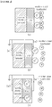
- the oxygen contained in the molten steel during the casting forms the metal oxide and moves to the inner wall of the nozzle body 41.
- electrons densely surrounding the metal oxide decompose the metal oxide into the oxygen ion and cations (metal ions).
- This decomposed oxygen ion is moved to the liner 43 having the excellent ion conductivity as shown in Figure 3c , and is discharged to the outside through pores of the nozzle body while forming oxygen gas.
- the cations are then absorbed into the molten steel.
- a dummy ring 45 may be formed on at least one of the upper side and the lower side with respect to the longitudinal direction of the liner 43 in order to secure a space corresponding to the volume expansion of the liner 43.
- the dummy ring 45 may be formed to have a length of about 1 to 2% with respect to a length of the liner 43.
- the dummy ring 45 may be formed of a material having a lower melting point than the contents constituting the liner 43. That is, the dummy ring 45 is formed on either the upper side or the lower side of the liner 43 when manufacturing the submerged entry nozzle 40, but during the casting, the dummy ring 45 may be dissolved and removed by a heat of the molten steel to secure the space for the volume expansion of the liner 43.
- the dummy ring 45 may be manufactured using a carbon-containing material such as graphite having a melting point higher than a firing temperature and lower than a casting temperature in manufacturing the submerged entry nozzle 40.
- a dummy ring 45/liner 43 or a dummy ring 45/liner 43/dummy ring 45 may be formed in the nozzle body 41 along the longitudinal direction of the nozzle body 41.
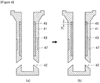
- the dummy ring 45 Before casting, as shown in Figure 4a , there is the dummy ring 45 on the one side of the liner 43, for example, on the upper side, but during the casting, as shown in Figure 4b , the dummy ring 45 is removed by the heat of the molten steel to form the space on the upper side or the upper side and the lower side of the liner 43, by the heat of the molten steel, the liner 43 expands in a volume by 'x' to fill the space formed while the dummy ring 45 is dissolving.
- the stress occurring between the liner 43 and the nozzle body 41 due to the volume expansion of the liner 43 may be relaxed, thereby cracking or damaging of the liner 43 may be suppressed or prevented.
- the slag line portion 47 may be defined on the outer wall of the submerged entry nozzle 40.
- the slag line portion 47 is configured to enhance a corrosion resistance against a slag (or a flux 62), the molten steel, and the like, and may be formed above the discharging hole 42, for example, around a mold level of the molten steel in the mold.
- the slag line portion 47 may be formed using various materials, for example, a mixed material of a calcia ⁇ magnesia partially stabilized zirconia, the graphite, or the like.
- the power supply 70 supplies the power, for example, a voltage or a current to the first electrode 72 and the second electrode (submerged entry nozzle 40) in the way that the first electrode 72 is as a cathode and the second electrode is as an anode.
- the power when the power is supplied to the first electrode 72 and the second electrode, the electrons move from the first electrode 72 to the second electrode side, and the oxygen ion decomposed at the interface between the molten steel and the submerged entry nozzle 40 moves in the moving direction of the electrons, that is from the molten steel to the nozzle body 41 side.
- the oxygen ion in the molten steel may move to the nozzle body 41 side through the liner 43 and may be discharged to the outside, and through this process, the nozzle clogging by the adhesion of the metal oxide to the inner hollow portion of the submerged entry nozzle 40 may be suppressed or prevented.
- the nozzle according to the embodiment of the present disclosure may include a process of preparing the raw material for forming the submerged entry nozzle 40, a process of injecting the raw material into the molding frame for forming the submerged entry nozzle 40 to form the molded product, and a process of forming the submerged entry nozzle 40 via firing the molded product.
- the molded product is drawn from the molding frame, and the molded product is fired at a temperature of about 1000 °C or less in the firing furnace to produce the submerged entry nozzle 40.
- the dummy ring 45 may maintain a shape formed during the forming of the molded product.
- the casting method according to the embodiment of the present disclosure is a method of casting the cast-piece 61 by injecting the molten steel 60 in the tundish 10 into the mold 50 through the submerged entry nozzle 40, oxygen contained in the molten steel may be discharged to the submerged entry nozzle side by electrically connecting the molten steel 60 and the submerged entry nozzle 40.
- the molten steel 60 in the tundish 10 is injected into the mold 50, and the power is supplied to the first electrode 72 and the nozzle body 41, which is the second electrode, by the power supply 70.
- the first electrode 72 is set to be the cathode and the second electrode is set to be the anode so that the current flows from the first electrode 72 to the second electrode side.
- the power supplied to the first electrode 72 and the second electrode by the power supply 70 may be adjusted to have a current density of about 0.1 to 10 mA/cm 2 . This is because the liner 43 defined on an inner portion the nozzle body 41 has the very high ion conductivity, so that oxygen ion may smoothly move even if the relatively small current flows. In this connection, when the current density is smaller than the suggested range, an ionization of the metal oxide and the movement of the oxygen ion are not smoothly carried out. Further, since the ionization of the metal oxide and the movement of the oxygen ion are smoothly carried out within the suggested range of the current density, it is not necessary to make the current density larger than the suggested range.
- the electrons move from the first electrode 72 to the nozzle body 41 which is the second electrode, and thus the current flows from the first electrode 72 to the second electrode.
- the electrons are concentrated around the metal oxide produced on the inner wall side of the submerged entry nozzle 40, the metal oxide is decomposed into the oxygen ion and the cations.
- the oxygen ion thus decomposed moves in the moving direction of the electrons, that is, from the molten steel to the nozzle body 41. At this time, the oxygen ion is transferred to the nozzle body 41 through the liner 43 produced in the inner wall of the submerged entry nozzle 40.
- the liner 43 Since the liner 43, the solid electrolyte, is permeable only to the oxygen ion, the cations dissolve into the molten steel and are absorbed. This process is continuously performed while the power is supplied, and it is possible to suppress or prevent the metal oxide from being produced and adhered to the inner wall of the submerged entry nozzle 40. Therefore, it is possible to prevent the nozzle clogging which may be caused by the formation and adhesion of the metal oxide.
- the submerged entry nozzle was manufactured forming the liner with the solid electrolyte on the inner wall portion of the submerged entry nozzle and the other portion without the liner.
- casting was performed under a test facility of a 13-ton scale of the molten steel.
- the power was supplied such that 2 mA/cm 2 of the current density was applied.
- a condition which may be producing a large amount of the Al 2 O 3 inclusion in the molten steel was applied. Thereafter, the submerged entry nozzle used in the test was cut and an inside thereof was observed.
- the nozzle, the casting apparatus and the casting method may improve the productivity of the cast-piece by suppressing or preventing the nozzle clogging in the continuous casting process for casting the cast-piece.
Landscapes
- Engineering & Computer Science (AREA)
- Mechanical Engineering (AREA)
- Manufacturing & Machinery (AREA)
- Casting Support Devices, Ladles, And Melt Control Thereby (AREA)
- Continuous Casting (AREA)
- Compositions Of Oxide Ceramics (AREA)
Abstract
Description
- The present disclosure relates to a nozzle, a casting apparatus and a casting method, and more particularly to a nozzle, a casting apparatus and a casting method capable of suppressing a clogging phenomenon via an electrochemical deoxidation reaction.
- Continuous casting process is a process in which a ladle containing a refined molten steel is placed in a continuous casting apparatus and then molten steel in a liquid state is transformed into a solid cast-piece by moving from the ladle to a mold through a tundish. In this connection, a submerged entry nozzle is located at the bottom of the tundish and moves the molten steel from the tundish to the mold, and is immersed in the molten steel and contacts with the molten steel for a long time. Therefore, an excellent durability is required. The submerged entry nozzle is made of Al2O3-C material, which is composed of alumina (Al2O3), which is excellent in a fire resistance and a corrosion resistance against a molten metal, and graphite (C), which has a small wettability in relation to an inclusion (slag component) and a small expansion amount and a good thermal conductivity.
- The submerged entry nozzle is a cylindrical refractory that acts as a flow path to supply the molten steel from the tundish to the mold. During the movement of the molten steel into the submerged entry nozzle, a clogging layer grows from an inner wall of the nozzle toward a center of the nozzle due to a temperature drop, an interfacial reaction at an interface between the molten steel and the nozzle inner wall, and an inclusion adhesion to the nozzle inner wall in the molten steel. This nozzle clogging causes interruption of the continuous casting process, which causes adverse effects such as a productivity and a cast-piece quality deterioration, etc. Therefore, in order to prevent such nozzle clogging, a porous type submerged entry nozzle which supplies inert gas from an inside of the nozzle to the molten steel to prevent adhesion of the inclusion by bubbles, a melting loss type nozzle which introducing a refractory which reacts with aluminum oxide which is mainly causing the nozzle clogging to form a low melting point compound to melt the nozzle clogging layer together with a nozzle material, and a refractory material which inhibits an adhesion of the inclusion or a contact with the molten steel are introduced.
- The present disclosure provides a nozzle, a casting apparatus and a casting method capable of preventing a nozzle clogging phenomenon via an electrochemical deoxidation reaction during the casting.
- The present disclosure provides a nozzle, a casting apparatus and a casting method for improving a casting process efficiency and a productivity.
- A nozzle according to an embodiment of the present disclosure may including: a nozzle body having an inner hollow portion through which a molten steel may move and a discharging hole through which the molten steel may move outside the inner hollow portion; and a liner surrounding at least a portion of an inner wall of the nozzle body and containing MgO stabilized ZrO2 (MSZ).
- The nozzle body may contain Al2O3, wherein the nozzle body may contain 20% by weight to 30% by weight of carbon content.
- The liner may contain 80 to 95% by weight of MgO stabilized ZrO2 and 5 to 20% by weight of carbon.
- The MgO stabilized ZrO2 may contain 8 to 15 mol% of magnesia (MgO).
- A dummy ring may be provided on at least one of a top and a bottom of the liner with respect to a longitudinal direction of the liner.
- The dummy ring may contain a carbon content.
- The dummy ring may have a length of 1 to 2% based on a total length of the liner.
- A casting apparatus according to an embodiment of the present disclosure may including: a tundish in which molten steel is received; a submerged entry nozzle connected to a bottom of the tundish wherein the submerged entry nozzle includes a nozzle body and a liner surrounding at least a portion of an inner wall of the nozzle body and containing MgO stabilized ZrO2 (MSZ); and a power supply electrically connecting the molten steel received in the tundish and the nozzle body with each other;
- The nozzle body may contain Al2O3, and the nozzle body may contain 20% by weight to 30% by weight of carbon content.
- The liner may contain 80 to 95% by weight of MgO stabilized ZrO2 and 5 to 20% by weight of carbon.
- The MgO stabilized ZrO2 containing 8 to 15 mol% of magnesia (MgO).
- A dummy ring may be provided on at least one of a bottom and a top of the liner with respect to a longitudinal direction of the liner.
- The dummy ring may contain a carbon content.
- The dummy ring may have a length of 1 to 2% based on a total length of the liner.
- The apparatus may include an electrode immersed in the molten steel in the tundish, and the power supply may apply a power to the electrode and the submerged entry nozzle.
- A casting method according to an embodiment of the present disclosure for casting a cast-piece by injecting a molten steel received in a tundish into a mold through a submerged entry nozzle, wherein the submerged entry nozzle may include a nozzle body connected to the tundish, and a liner defined on an inner wall of the nozzle body and containing MgO stabilized ZrO2, wherein the molten steel and the nozzle body may be electrically connected with each other to discharge oxygens contained in the molten steel to the submerged entry nozzle side.
- When the molten steel and the nozzle body are electrically connected with each other, the metal oxide produced in the molten steel may be decomposed into an oxygen ion and a cation, and, then, the oxygen ion may be transferred to the nozzle body through the liner, such that the oxygen in the molten steel may be discharged to the submerged entry nozzle side.
- The molten steel and the submerged entry nozzle may be electrically connected with each other while using the molten steel as a cathode and using the submerged entry nozzle as an anode.
- In electrically connecting the molten steel and the submerged entry nozzle with each other, 0.1 to 10 mA/cm2 of a current density may be applied.
- A dummy ring may be provided on at least one of a top and a bottom of the liner, and the dummy ring may be dissolved in casting the cast-piece to form a space.
- The nozzle, the casting apparatus and the casting method according to the present disclosure may suppress or prevent the clogging of the inner hollow portion of the nozzle, for example, the submerged entry nozzle used in the casting process. That is, by forming the liner using a solid electrolyte enabling the electrochemical deoxidation at the inner hollow portion of the nozzle in contact with the molten steel at a casting temperature and electrically connecting the molten steel and the submerged entry nozzle, it is possible to suppress or prevent the nozzle clogging due to an inclusion such as the metal oxide or the like stacking on the inner wall of the submerged entry nozzle which is contacting the molten steel during casting. Through this, an interfacial oxygen concentration on the inner wall of the nozzle and a wettability of the inner wall of the nozzle and the molten steel may be reduced. Thus, the inclusion formation and the wettability of the molten steel, which are the main causes of the nozzle clogging are improved, so that the nozzle clogging may be suppressed or prevented. Therefore, it is possible to solve problems such as suspension of casting result from the nozzle clogging, thereby improving a casting efficiency and the productivity, and it is possible to improve a quality of the cast-piece manufactured using this. Further, a lifetime of the nozzle may be increased to reduce a time and cost of replacing the nozzle.
- Further, since the liner is formed using the solid electrolyte having an excellent ion conductivity inside the submerged entry nozzle, a power consumption for inhibiting the inclusion formation may be reduced.
-
-
Figure 1 is a schematic view of a casting apparatus according to an embodiment of the present disclosure. -
Figure 2 is a cross-sectional view of a nozzle applied to a casting apparatus according to an embodiment of the present disclosure. -
Figure 3 is a schematic diagram of a deoxidation reaction occurring in an inner hollow portion of a nozzle during the casting. -
Figure 4 is a cross-sectional view showing a change in an internal structure of the nozzle during the casting. - An embodiment of the present disclosure will now be described in detail with reference to the accompanying drawings. However, the present disclosure is not limited to an embodiment disclosed below, but may be embodied in various different forms. An embodiment of the present disclosure, however, is provided in order to make the present disclosure complete and to give a complete knowledge of the invention to those of ordinary skill in the art. The drawings may be exaggerated or expanded to illustrate an embodiment of the present disclosure, wherein like reference numerals refer to like elements throughout.
-
Figure 1 is a schematic view of a casting apparatus according to an embodiment of the present disclosure,Figure 2 is a cross-sectional view of a nozzle applied to a casting apparatus according to an embodiment of the present disclosure,Figure 3 is a schematic diagram of a deoxidation reaction occurring in an inner hollow portion of a nozzle during the casting,Figure 4 is a cross-sectional view showing a change in an internal structure of the nozzle during the casting. - Referring to
Figure 1 , the casting apparatus, for example a continuous casting apparatus, may be provided with a tundish 10 for storing and dispensing amolten steel 60 from a ladle, which is a container for refined molten steel, astopper 20 and asliding plate 30 for adjusting a flow rate of themolten steel 60, a submergedentry nozzle 40 discharging themolten steel 60 to amold 50 and themold 50 for solidifying themolten steel 60 into a cast-piece 61. AlthoughFigure 1 shows that thestopper 20 and thesliding plate 30 are provided at the same time in order to adjust the flow rate of the molten steel, in actual operation, either thestopper 20 or thesliding plate 30 may be used. Further, the casting apparatus may include apower supply 70 for supplying a voltage to the molten steel in the tundish and the submergedentry nozzle 40. - Referring to
Figure 2 , the submergedentry nozzle 40 may include an inner hollow portion through which the molten steel may move, anozzle body 41 having adischarging hole 42 through which the molten steel may move outside, for example to the mold, aliner 43 configured to surround at least a part of an inner wall of thenozzle body 41 and containing MgO stabilized ZrO2 (MSZ). Further, although not shown, the submergedentry nozzle 40 may include aslag line portion 47 surrounding at least a portion of an outer wall of thenozzle body 41. - The
nozzle body 41 may be formed in a cylindrical shape having at least an open top so as to have the inner hollow portion through which the molten steel may move. Further, in a lower side of thenozzle body 41, thedischarging hole 42 through which the molten steel may be discharged to the outside from the inner hollow portion may be formed. Thenozzle body 41 may be formed using Al2O3-C. In this connection, thenozzle body 41 may contain about 20 to 30 % by weight of the C content so as to have a conductivity. This is to form a conducting circuit between the submergedentry nozzle 40 and the molten steel flowing through the submergedentry nozzle 40. - The
liner 43 may be defined on the inner wall of thenozzle body 41, that is, a surface contacting the molten steel. Theliner 43 may be defined over the entire inner wall of thenozzle body 41, but may be defined from an upper side of thenozzle body 41 to above of thedischarging hole 42. Accordingly, theliner 43 may be defined in a hollow cylindrical shape having an opening inside of thenozzle body 41 in a vertical direction along the inner wall of thenozzle body 41. - The
liner 43 is defined on the inner wall of thenozzle body 41 to move oxygen ion in the molten steel toward thenozzle body 41. Theliner 43 may be formed of the MgO stabilized ZrO2 (MSZ), which is well-known as a material having an excellent ion conductivity. The MgO stabilized ZrO2 is a solid electrolyte having a property that an ion guides electricity in a solid state, and is applied to a solid fuel cell, a probe for measuring an oxygen concentration in a molten metal, and the like. - In the present disclosure, this MgO stabilized ZrO2 (MSZ) is used as the
liner 43 to induce the oxygen ion in the molten steel toward thenozzle body 41 to suppress or prevent the formation of the inclusion, for example metal oxides such as SiO2, Al2O3, TiO2, and the like at the inner wall of the submergedentry nozzle 40. - During the casting, the oxygen contained in the molten steel forms the metal oxide at an interface between the molten steel and the inner wall of the submerged
entry nozzle 40 due to its property to be activated at the interface. This produced metal oxide has a high interfacial energy with the molten steel and is spontaneously moved and adhered to the inner wall of the submergedentry nozzle 40 in the molten steel. As this process repeats and continues, a nozzle clogging occurs at the inner hollow portion of the submergedentry nozzle 40. In the present disclosure, theliner 43 is defined on the inner wall of thenozzle body 41 using the solid electrolyte having the excellent ion conductivity, and the oxygen ion is induced to the outside by electrically connecting the molten steel and the submergedentry nozzle 40, that is thenozzle body 41 so that the adhesion of the metal oxide to the inner wall of the submergedentry nozzle 40 may be suppressed or prevented. - A mechanism for preventing the metal oxide formation and adhesion will be described below.
- Referring to
Figure 3a , the oxygen contained in the molten steel during the casting forms the metal oxide and moves to the inner wall of thenozzle body 41. Then, as shown inFigure 3b , when the molten steel and thenozzle body 41 are electrically connected, electrons densely surrounding the metal oxide decompose the metal oxide into the oxygen ion and cations (metal ions). This decomposed oxygen ion is moved to theliner 43 having the excellent ion conductivity as shown inFigure 3c , and is discharged to the outside through pores of the nozzle body while forming oxygen gas. The cations are then absorbed into the molten steel. Through this process, that is, deoxidation, the oxygen in the molten steel is discharged to the outside the molten steel, thereby the nozzle clogging may be suppressed of prevented by inhibiting the formation and adhesion of the metal oxide in the submergedentry nozzle 40. - The
liner 43 may contain 80 to 95% by weight of MgO stabilized ZrO2 (MSZ) and 5 to 20% by weight of carbon content. In this connection, the MgO stabilized ZrO2 (MSZ) may be composed of magnesia (MgO) of about 8 to 15 mol% and the rest of zirconia (ZrO2) in order to inhibit a volume change due to a phase change based on a temperature change. Using the magnesia as a stabilizer in the zirconia as described above, the zirconia may maintain a relatively stable phase even at the temperature change, so that it is possible to prevent cracking or damaging of theliner 43 during the casting. - On the other hand, even if the
liner 43 is manufactured using the MgO stabilized ZrO2 stable to the temperature change, a volume expansion based on the temperature change may not be completely suppressed. Further, a coefficient of thermal expansion of theliner 43 and thenozzle body 41 are different from each other, and the coefficient of thermal expansion of theliner 43 is larger than the coefficient of thermal expansion of thenozzle body 41 so that a stress occurs between theliner 43 and thenozzle body 41 due to the volume expansion of theliner 43 during the casting, may result in cracking or damaging of theliner 43. - Therefore, a
dummy ring 45 may be formed on at least one of the upper side and the lower side with respect to the longitudinal direction of theliner 43 in order to secure a space corresponding to the volume expansion of theliner 43. Thedummy ring 45 may be formed to have a length of about 1 to 2% with respect to a length of theliner 43. When the length of thedummy ring 45 is shorter than the specified range, the breakage of theliner 43 is inevitable because thedummy ring 45 may not adequately cope with the volume expansion of theliner 43, and when the length of thedummy ring 45 is longer than the specified range, thenozzle body 41 may be exposed to the molten steel and the metal oxide may be produced and adhered to thenozzle body 41. Thedummy ring 45 does not have to be formed if it may secure a space according to the volume expansion of theliner 43, thedummy ring 45 is inevitably formed because it is difficult to secure the space corresponding to the volume expansion of theliner 43 due to its manufacturing characteristics of the submergedentry nozzle 40. That is, the process of manufacturing the submergedentry nozzle 40 includes a press molding process and a firing process after injecting a raw material constituting the submergedentry nozzle 40 into a molding frame, this is because it is difficult to secure a specific position that is, the space corresponding to the volume expansion of theliner 43, when the raw material is injected into the molding frame. Thus, thedummy ring 45 may be formed of a material having a lower melting point than the contents constituting theliner 43. That is, thedummy ring 45 is formed on either the upper side or the lower side of theliner 43 when manufacturing the submergedentry nozzle 40, but during the casting, thedummy ring 45 may be dissolved and removed by a heat of the molten steel to secure the space for the volume expansion of theliner 43. Thus, thedummy ring 45 may be manufactured using a carbon-containing material such as graphite having a melting point higher than a firing temperature and lower than a casting temperature in manufacturing the submergedentry nozzle 40. - According to such the structure, a
dummy ring 45/liner 43 or adummy ring 45/liner 43/dummy ring 45 may be formed in thenozzle body 41 along the longitudinal direction of thenozzle body 41. Before casting, as shown inFigure 4a , there is thedummy ring 45 on the one side of theliner 43, for example, on the upper side, but during the casting, as shown inFigure 4b , thedummy ring 45 is removed by the heat of the molten steel to form the space on the upper side or the upper side and the lower side of theliner 43, by the heat of the molten steel, theliner 43 expands in a volume by 'x' to fill the space formed while thedummy ring 45 is dissolving. Thus, the stress occurring between theliner 43 and thenozzle body 41 due to the volume expansion of theliner 43 may be relaxed, thereby cracking or damaging of theliner 43 may be suppressed or prevented. - Further, the
slag line portion 47 may be defined on the outer wall of the submergedentry nozzle 40. Theslag line portion 47 is configured to enhance a corrosion resistance against a slag (or a flux 62), the molten steel, and the like, and may be formed above the discharginghole 42, for example, around a mold level of the molten steel in the mold. Theslag line portion 47 may be formed using various materials, for example, a mixed material of a calcia·magnesia partially stabilized zirconia, the graphite, or the like. - The
power supply 70 electrically connects the molten steel in thetundish 10 and the submergedentry nozzle 40. In this connection, afirst electrode rod 72 for supplying a power to the molten steel in the tundish may be provided, and the submergedentry nozzle 40 may be used as a second electrode. In order to supply the power to the molten steel in the tundish, thefirst electrode 72 may be provided to be immersed in the molten steel in the tundish, and thefirst electrode rod 72 may be formed of the same material as the submergedentry nozzle 40, that is, thenozzle body 41. Further, thepower supply 70 supplies the power, for example, a voltage or a current to thefirst electrode 72 and the second electrode (submerged entry nozzle 40) in the way that thefirst electrode 72 is as a cathode and the second electrode is as an anode. Thus, when the power is supplied to thefirst electrode 72 and the second electrode, the electrons move from thefirst electrode 72 to the second electrode side, and the oxygen ion decomposed at the interface between the molten steel and the submergedentry nozzle 40 moves in the moving direction of the electrons, that is from the molten steel to thenozzle body 41 side. Therefore, the oxygen ion in the molten steel may move to thenozzle body 41 side through theliner 43 and may be discharged to the outside, and through this process, the nozzle clogging by the adhesion of the metal oxide to the inner hollow portion of the submergedentry nozzle 40 may be suppressed or prevented. - Hereinafter, a method for manufacturing a nozzle according to an embodiment of the present disclosure will be described.
- The nozzle according to the embodiment of the present disclosure may include a process of preparing the raw material for forming the submerged
entry nozzle 40, a process of injecting the raw material into the molding frame for forming the submergedentry nozzle 40 to form the molded product, and a process of forming the submergedentry nozzle 40 via firing the molded product. - The process of preparing the raw material may include processes of preparing a raw material for forming the
nozzle body 41, a raw material for forming theliner 43 and a raw material for forming thedummy ring 45. - When the raw materials are prepared, each raw material is injected into the molding frame to form the molded product of the submerged
entry nozzle 40. At this time, a cylindrical core material may be inserted into the molding frame, and a spacer for forming the liner and the dummy ring may be inserted to be spaced apart from the core material. Then, between the spacer and the core material, the raw materials for forming theliner 43 and thedummy ring 45 are sequentially injected, and between the spacer and the molding frame, the raw material for forming thenozzle body 41 is injected. After the spacer is removed, the raw materials injected into the molding frame are pressed to form the molded product for forming the submergedentry nozzle 40. - Thereafter, the molded product is drawn from the molding frame, and the molded product is fired at a temperature of about 1000 °C or less in the firing furnace to produce the submerged
entry nozzle 40. In the process of firing the molded product, thedummy ring 45 may maintain a shape formed during the forming of the molded product. - When the casting is performed using the thus formed submerged
entry nozzle 40, thedummy ring 45 is dissolved and removed by a heat of the molten steel, thereby the space corresponding to the volume expansion of theliner 43 may be easily secured at the upper portion or the lower portion of theliner 43. Accordingly, when the volume of theliner 43 is expanded by the molten steel during the casting, the space in which thedummy ring 45 is removed may prevent cracking or damaging in theliner 43. - Hereinafter, a method for casting a cast-piece using a casting apparatus according to an embodiment of the present disclosure will be described.
- The casting method according to the embodiment of the present disclosure is a method of casting the cast-
piece 61 by injecting themolten steel 60 in thetundish 10 into themold 50 through the submergedentry nozzle 40, oxygen contained in the molten steel may be discharged to the submerged entry nozzle side by electrically connecting themolten steel 60 and the submergedentry nozzle 40. - A circuit may be configured to electrically connect the
molten steel 60 and the submergedentry nozzle 40 prior to casting. The circuit is configured to immerse thefirst electrode 72 into the molten steel in the tundish and connect thefirst electrode 72 and the second electrode, that is, thenozzle body 41 using a wire. Then, thefirst electrode 72 and the second electrode are connected to thepower supply 70 provided outside by the wire. - Then, when casting starts, the
molten steel 60 in thetundish 10 is injected into themold 50, and the power is supplied to thefirst electrode 72 and thenozzle body 41, which is the second electrode, by thepower supply 70. In this connection, thefirst electrode 72 is set to be the cathode and the second electrode is set to be the anode so that the current flows from thefirst electrode 72 to the second electrode side. - The power supplied to the
first electrode 72 and the second electrode by thepower supply 70 may be adjusted to have a current density of about 0.1 to 10 mA/cm2. This is because theliner 43 defined on an inner portion thenozzle body 41 has the very high ion conductivity, so that oxygen ion may smoothly move even if the relatively small current flows. In this connection, when the current density is smaller than the suggested range, an ionization of the metal oxide and the movement of the oxygen ion are not smoothly carried out. Further, since the ionization of the metal oxide and the movement of the oxygen ion are smoothly carried out within the suggested range of the current density, it is not necessary to make the current density larger than the suggested range. - When the power is supplied to the
first electrode 72 and the second electrode thus, the electrons move from thefirst electrode 72 to thenozzle body 41 which is the second electrode, and thus the current flows from thefirst electrode 72 to the second electrode. Describe again with reference toFigure 3 , when the power is supplied to thefirst electrode 72 and the second electrode, the electrons are concentrated around the metal oxide produced on the inner wall side of the submergedentry nozzle 40, the metal oxide is decomposed into the oxygen ion and the cations. The oxygen ion thus decomposed moves in the moving direction of the electrons, that is, from the molten steel to thenozzle body 41. At this time, the oxygen ion is transferred to thenozzle body 41 through theliner 43 produced in the inner wall of the submergedentry nozzle 40. Since theliner 43, the solid electrolyte, is permeable only to the oxygen ion, the cations dissolve into the molten steel and are absorbed. This process is continuously performed while the power is supplied, and it is possible to suppress or prevent the metal oxide from being produced and adhered to the inner wall of the submergedentry nozzle 40. Therefore, it is possible to prevent the nozzle clogging which may be caused by the formation and adhesion of the metal oxide. - Hereinafter, test results using a casting apparatus according to an embodiment of the present disclosure will be described below.
- For the test, the submerged entry nozzle was manufactured forming the liner with the solid electrolyte on the inner wall portion of the submerged entry nozzle and the other portion without the liner. Using the submerged entry nozzle thus produced, casting was performed under a test facility of a 13-ton scale of the molten steel. In this connection, the power was supplied such that 2 mA/cm2 of the current density was applied. Further, in order to accelerate the nozzle clogging, a condition which may be producing a large amount of the Al2O3 inclusion in the molten steel was applied. Thereafter, the submerged entry nozzle used in the test was cut and an inside thereof was observed.
- As a result of the experiment, it was confirmed that the inclusion layer of 0.3 mm or less was adhered to the region where the liner was defined, and in the region B where the liner was not defined, a mixture of the inclusion and an impurity had the inclusion layer of about 1.8 to 3.5 mm.
- Through this test, it was confirmed that when the liner containing the solid electrolyte is formed on the submerged entry nozzle and the molten steel and the submerged entry nozzle are electrically connected, the oxygen in the molten steel is removed and the formation and adhesion of the metal oxide at the inner wall of the submerged entry nozzle is prevented.
- Although the preferred embodiments of the present disclosure have been shown and described, those skilled in the art will be understood that the present disclosure is not intended to be limited to the embodiments shown herein but is intended to cover alternatives, modifications, and equivalents as may be included within the spirit and scope of the present disclosure as defined by the appended claims. Accordingly, the technical protection scope of the present disclosure should be defined by the following claims.
- According to the present disclosure, the nozzle, the casting apparatus and the casting method may improve the productivity of the cast-piece by suppressing or preventing the nozzle clogging in the continuous casting process for casting the cast-piece.
Claims (16)
- a nozzle comprising:a nozzle body having an inner hollow portion through which molten steel moves, and a discharging hole defined therein through which the molten steel moves outside the inner hollow portion; anda liner surrounding at least a portion of an inner wall of the nozzle body and containing MgO stabilized ZrO2 (MSZ).
- The nozzle according to claim 1, wherein the nozzle body contains Al2O3, wherein the nozzle body contains 20% by weight to 30% by weight of carbon content.
- The nozzle according to claim 1, wherein the liner contains 80 to 95% by weight of MgO stabilized ZrO2 and 5 to 20% by weight of carbon.
- The nozzle of claim 3, wherein the MgO stabilized ZrOz contains 8 to 15 mol% of magnesia (MgO).
- The nozzle of claim 4, wherein a dummy ring is provided on at least one of a top and a bottom of the liner with respect to a longitudinal direction of the liner.
- The nozzle of claim 5, wherein the dummy ring contains a carbon content.
- The nozzle of claim 6, wherein the dummy ring has a length of 1 to 2% based on a total length of the liner.
- A casting apparatus comprising:a tundish receiving molten steel therein;a submerged entry nozzle connected to a bottom of the tundish, wherein the submerged entry nozzle includes a nozzle body, and a liner surrounding at least a portion of an inner wall of the nozzle body, wherein the liner contains MgO stabilized ZrO2 (MSZ); anda power supply electrically connecting the molten steel received in the tundish and the nozzle body with each other.
- The apparatus of claim 8, wherein the nozzle body contains Al2O3,
wherein the nozzle body contains 20% by weight to 30% by weight of carbon content,
wherein the liner contains 80 to 95% by weight of MgO stabilized ZrO2, and 5 to 20% by weight of carbon, wherein the MgO stabilized ZrO2 contains 8 to 15 mol% of magnesia (MgO). - The apparatus of claim 9, wherein a dummy ring is provided on at least one of a top and a bottom of the liner with respect to a longitudinal direction of the liner.
- The apparatus of claim 8, wherein the apparatus includes an electrode immersed in the molten steel in the tundish,
wherein the power supply applies a power to the electrode and the submerged entry nozzle. - A casting method for casting a cast-piece by injecting molten steel received in a tundish into a mold through a submerged entry nozzle,wherein the submerged entry nozzle includes a nozzle body connected to the tundish, and a liner defined on an inner wall of the nozzle body, wherein the liner contains MgO stabilized ZrO2,wherein the method includes electrically connecting the molten steel and the nozzle body with each other to discharge oxygens contained in the molten steel to a side of the submerged entry nozzle.
- The method of claim 12, wherein when the molten steel and the nozzle body are electrically connected with each other, metal oxides produced in the molten steel are decomposed into oxygen ions and cations, and, then, the oxygen ions are transferred through the liner to the nozzle body, such that oxygens in the molten steel are discharged to a side of the submerged entry nozzle.
- The method of claim 13, wherein the molten steel and the submerged entry nozzle are electrically connected with each other while using the molten steel as a cathode and using the submerged entry nozzle as an anode.
- The method of claim 14, wherein in electrically connecting the molten steel and the submerged entry nozzle with each other, 0.1 to 10 mA/cm2 of a current density is applied.
- The method of claim 13, wherein a dummy ring is provided on at least one of a top and a bottom of the liner, wherein the dummy ring is dissolved during casting the cast-piece to form a space.
Applications Claiming Priority (3)
| Application Number | Priority Date | Filing Date | Title |
|---|---|---|---|
| KR1020150167725A KR101834419B1 (en) | 2015-11-27 | 2015-11-27 | Casting apparatus and casting method using the same |
| KR1020150167722A KR101825133B1 (en) | 2015-11-27 | 2015-11-27 | Nozzle |
| PCT/KR2015/014134 WO2017090819A1 (en) | 2015-11-27 | 2015-12-22 | Nozzle, casting device, and casting method |
Publications (3)
| Publication Number | Publication Date |
|---|---|
| EP3381587A1 true EP3381587A1 (en) | 2018-10-03 |
| EP3381587A4 EP3381587A4 (en) | 2018-10-03 |
| EP3381587B1 EP3381587B1 (en) | 2020-02-05 |
Family
ID=58763807
Family Applications (1)
| Application Number | Title | Priority Date | Filing Date |
|---|---|---|---|
| EP15909368.1A Active EP3381587B1 (en) | 2015-11-27 | 2015-12-22 | Nozzle, casting device, and casting method |
Country Status (4)
| Country | Link |
|---|---|
| EP (1) | EP3381587B1 (en) |
| JP (1) | JP6582132B2 (en) |
| CN (1) | CN108778568B (en) |
| WO (1) | WO2017090819A1 (en) |
Cited By (2)
| Publication number | Priority date | Publication date | Assignee | Title |
|---|---|---|---|---|
| EP3827912A1 (en) * | 2019-11-26 | 2021-06-02 | Refractory Intellectual Property GmbH & Co. KG | An exchangeable nozzle for a nozzle changer system, a method for manufacturing such a nozzle, a nozzle changer system comprising such a nozzle and a tundish comprising such a nozzle changer system |
| RU2802293C1 (en) * | 2019-11-26 | 2023-08-24 | Рифрэктори Интеллектчуал Проперти Гмбх Унд Ко. Кг | Replaceable pouring nozzle for pouring nozzle replacing system, method for manufacturing such pouring nozzle, pouring nozzle replacing system containing pouring nozzle, and intermediate filling device containing such a pouring nozzle replacing system |
Families Citing this family (7)
| Publication number | Priority date | Publication date | Assignee | Title |
|---|---|---|---|---|
| CN108145144B (en) * | 2017-12-27 | 2023-08-15 | 武汉科技大学 | Ladle working lining for controlling molten steel slag winding |
| CN109909466B (en) * | 2019-03-19 | 2023-12-19 | 沈阳麒飞新型材料科技有限公司 | Continuous pouring equipment with multiple water gaps |
| CN111036891A (en) * | 2019-11-29 | 2020-04-21 | 浙江科宇金属材料有限公司 | Pouring pipe for vertical casting |
| JP7393638B2 (en) * | 2020-01-17 | 2023-12-07 | 日本製鉄株式会社 | Continuous steel casting method |
| CN111482589B (en) * | 2020-04-28 | 2023-05-09 | 宋振亚 | Manufacturing method of long-service-life metering nozzle |
| CN117920984A (en) * | 2024-02-01 | 2024-04-26 | 江苏省沙钢钢铁研究院有限公司 | Titanium-containing welding wire steel and preparation method thereof |
| CN118950996A (en) * | 2024-07-05 | 2024-11-15 | 南京钢铁股份有限公司 | A method for preventing nodules in submerged nozzles based on electric field to suppress inclusion adsorption |
Family Cites Families (25)
| Publication number | Priority date | Publication date | Assignee | Title |
|---|---|---|---|---|
| GB2056430B (en) * | 1979-08-18 | 1982-12-08 | Akechi Taikarenga Kk | Immersion nozzle for continuous casting of molten steel |
| JPS5785659A (en) * | 1980-11-18 | 1982-05-28 | Kawasaki Steel Corp | Preventive method for deposition of alumina from molten steel flow and nozzle for molten steel |
| JPH0775763B2 (en) * | 1985-10-25 | 1995-08-16 | 住友化学工業株式会社 | Nozzle for continuous casting |
| JPS62192254A (en) * | 1986-02-17 | 1987-08-22 | Sumitomo Metal Ind Ltd | Device for preventing clogging of molten metal flow passage |
| DE3842690C2 (en) * | 1988-12-19 | 1998-04-30 | Didier Werke Ag | Refractory connection and induction coil therefor |
| JPH0722808B2 (en) * | 1988-12-27 | 1995-03-15 | 住友金属工業株式会社 | Method for preventing deposition of deposits on the immersion nozzle |
| JPH08132193A (en) * | 1994-10-31 | 1996-05-28 | Akechi Ceramics Kk | Nozzle for continuous casting |
| JPH08155601A (en) * | 1994-12-07 | 1996-06-18 | Nippon Steel Corp | Nozzle for continuous casting |
| DE19923800C1 (en) * | 1999-05-19 | 2001-03-22 | Sms Demag Ag | Method and device for holding and tapping molten metal |
| JP4231176B2 (en) * | 1999-12-13 | 2009-02-25 | 新日本製鐵株式会社 | Stopper for metallurgy container and / or upper nozzle |
| JP4150142B2 (en) * | 1999-12-13 | 2008-09-17 | 新日本製鐵株式会社 | Sliding nozzle of metallurgical container |
| JP3506655B2 (en) * | 2000-04-28 | 2004-03-15 | 明智セラミックス株式会社 | Continuous casting nozzle |
| JP3747848B2 (en) * | 2000-12-25 | 2006-02-22 | 住友金属工業株式会社 | Continuous casting method |
| JP2003040672A (en) * | 2001-05-21 | 2003-02-13 | Shinagawa Refract Co Ltd | Refractory used for fireproof member for continuous steel casting |
| JP3896908B2 (en) * | 2002-06-21 | 2007-03-22 | 住友金属工業株式会社 | Continuous casting method for molten steel |
| JP4282005B2 (en) * | 2004-01-19 | 2009-06-17 | 黒崎播磨株式会社 | Immersion nozzle and method of manufacturing the immersion nozzle |
| JP4533051B2 (en) * | 2004-09-06 | 2010-08-25 | 黒崎播磨株式会社 | Continuous casting nozzle having an inner hole |
| CN101176914A (en) * | 2006-11-10 | 2008-05-14 | 宝山钢铁股份有限公司 | A method for preventing clogging and reducing erosion of continuous casting nozzle of steel casting furnace |
| JP5166302B2 (en) * | 2009-01-26 | 2013-03-21 | 黒崎播磨株式会社 | Continuous casting nozzle |
| JP5088400B2 (en) * | 2010-06-18 | 2012-12-05 | 住友金属工業株式会社 | Steel continuous casting method |
| KR20130010392A (en) * | 2011-07-18 | 2013-01-28 | 주식회사 포스코 | Apparatus for molten metal treatment |
| WO2013081113A1 (en) * | 2011-12-01 | 2013-06-06 | 黒崎播磨株式会社 | Refractory and nozzle for casting |
| WO2013190594A1 (en) * | 2012-06-20 | 2013-12-27 | 新日鐵住金株式会社 | Submerged entry nozzle for continuous casting and continous casting method using same |
| KR101489377B1 (en) * | 2013-12-06 | 2015-02-03 | 주식회사 포스코 | Apparatus for molten metal treatment and method for molten metal treatment |
| JP5818037B2 (en) * | 2014-02-28 | 2015-11-18 | 品川リフラクトリーズ株式会社 | Immersion nozzle for continuous casting |
-
2015
- 2015-12-22 EP EP15909368.1A patent/EP3381587B1/en active Active
- 2015-12-22 CN CN201580084876.1A patent/CN108778568B/en active Active
- 2015-12-22 WO PCT/KR2015/014134 patent/WO2017090819A1/en not_active Ceased
- 2015-12-22 JP JP2018526083A patent/JP6582132B2/en active Active
Cited By (4)
| Publication number | Priority date | Publication date | Assignee | Title |
|---|---|---|---|---|
| EP3827912A1 (en) * | 2019-11-26 | 2021-06-02 | Refractory Intellectual Property GmbH & Co. KG | An exchangeable nozzle for a nozzle changer system, a method for manufacturing such a nozzle, a nozzle changer system comprising such a nozzle and a tundish comprising such a nozzle changer system |
| WO2021104696A1 (en) * | 2019-11-26 | 2021-06-03 | Refractory Intellectual Property Gmbh & Co. Kg | An exchangeable nozzle for a nozzle changer system, a method for manufacturing such a nozzle, a nozzle changer system comprising such a nozzle and a tundish comprising such a nozzle changer system |
| RU2802293C1 (en) * | 2019-11-26 | 2023-08-24 | Рифрэктори Интеллектчуал Проперти Гмбх Унд Ко. Кг | Replaceable pouring nozzle for pouring nozzle replacing system, method for manufacturing such pouring nozzle, pouring nozzle replacing system containing pouring nozzle, and intermediate filling device containing such a pouring nozzle replacing system |
| US12138682B2 (en) | 2019-11-26 | 2024-11-12 | Refractory Intellectual Property Gmbh & Co. Kg | Exchangeable nozzle for a nozzle changer system, a method for manufacturing such a nozzle, a nozzle changer system comprising such a nozzle and a tundish comprising such a nozzle changer system |
Also Published As
| Publication number | Publication date |
|---|---|
| JP6582132B2 (en) | 2019-09-25 |
| EP3381587B1 (en) | 2020-02-05 |
| CN108778568A (en) | 2018-11-09 |
| WO2017090819A1 (en) | 2017-06-01 |
| JP2018534147A (en) | 2018-11-22 |
| CN108778568B (en) | 2021-03-12 |
| EP3381587A4 (en) | 2018-10-03 |
Similar Documents
| Publication | Publication Date | Title |
|---|---|---|
| EP3381587B1 (en) | Nozzle, casting device, and casting method | |
| EP2106866A1 (en) | Continuous casting method of steel | |
| JP5562962B2 (en) | Oxygen generating metal anode operating at high current density for aluminum reduction cells | |
| JP7712569B2 (en) | Continuous casting method for steel | |
| KR101834419B1 (en) | Casting apparatus and casting method using the same | |
| EP1348503B1 (en) | Continuous casting method using a molten steel feeder | |
| KR101825133B1 (en) | Nozzle | |
| JP4231176B2 (en) | Stopper for metallurgy container and / or upper nozzle | |
| KR101120110B1 (en) | Device for continuous casting and method thereof | |
| KR100916145B1 (en) | Refractory of the immersion nozzle for continuous casting | |
| KR101639753B1 (en) | Nozzle and manufacturing method of the same | |
| EP3078434A1 (en) | Molten metal treating apparatus and molten metal treating method | |
| KR101437763B1 (en) | Porous metal shroud system for anode of electrolytic reduction apparatus | |
| EP3527305A1 (en) | Nozzle and manufacturing method therefor | |
| Kim et al. | Electrochemical method for controlling the interfacial oxygen in molten Fe with ZrO2 based solid electrolyte | |
| JP2001170742A (en) | Sliding nozzle of metallurgical vessel | |
| JP2003200242A (en) | Immersion nozzle for continuous casting and continuous casting method for molten steel | |
| JP6419331B2 (en) | Immersion nozzle for continuous casting | |
| EP1870182B1 (en) | Process for the casting of molten alloy | |
| KR102239241B1 (en) | Apparatus and method for preventing from nozzle clogging | |
| KR101129320B1 (en) | A non-metallic inclusion decomposition method using electrochemical refining method | |
| KR101639749B1 (en) | Nozzle and method for producing the same | |
| JP2017178707A (en) | Production method of glass substrate and production device of glass substrate | |
| JP2017116315A (en) | Oxygen sensor and manufacturing method thereof | |
| JP2013224480A (en) | Method for producing steel for saw wire |
Legal Events
| Date | Code | Title | Description |
|---|---|---|---|
| STAA | Information on the status of an ep patent application or granted ep patent |
Free format text: STATUS: THE INTERNATIONAL PUBLICATION HAS BEEN MADE |
|
| PUAI | Public reference made under article 153(3) epc to a published international application that has entered the european phase |
Free format text: ORIGINAL CODE: 0009012 |
|
| STAA | Information on the status of an ep patent application or granted ep patent |
Free format text: STATUS: REQUEST FOR EXAMINATION WAS MADE |
|
| 17P | Request for examination filed |
Effective date: 20180522 |
|
| A4 | Supplementary search report drawn up and despatched |
Effective date: 20180731 |
|
| AK | Designated contracting states |
Kind code of ref document: A1 Designated state(s): AL AT BE BG CH CY CZ DE DK EE ES FI FR GB GR HR HU IE IS IT LI LT LU LV MC MK MT NL NO PL PT RO RS SE SI SK SM TR |
|
| AX | Request for extension of the european patent |
Extension state: BA ME |
|
| STAA | Information on the status of an ep patent application or granted ep patent |
Free format text: STATUS: EXAMINATION IS IN PROGRESS |
|
| DAV | Request for validation of the european patent (deleted) | ||
| DAX | Request for extension of the european patent (deleted) | ||
| 17Q | First examination report despatched |
Effective date: 20190211 |
|
| REG | Reference to a national code |
Ref country code: DE Ref legal event code: R079 Ref document number: 602015046627 Country of ref document: DE Free format text: PREVIOUS MAIN CLASS: B22D0041540000 Ipc: B22D0011160000 |
|
| GRAP | Despatch of communication of intention to grant a patent |
Free format text: ORIGINAL CODE: EPIDOSNIGR1 |
|
| STAA | Information on the status of an ep patent application or granted ep patent |
Free format text: STATUS: GRANT OF PATENT IS INTENDED |
|
| RIC1 | Information provided on ipc code assigned before grant |
Ipc: B22D 41/50 20060101ALI20190524BHEP Ipc: B22D 41/54 20060101ALI20190524BHEP Ipc: B22D 46/00 20060101ALI20190524BHEP Ipc: B22D 11/16 20060101AFI20190524BHEP Ipc: B22D 41/24 20060101ALI20190524BHEP |
|
| INTG | Intention to grant announced |
Effective date: 20190701 |
|
| GRAS | Grant fee paid |
Free format text: ORIGINAL CODE: EPIDOSNIGR3 |
|
| GRAJ | Information related to disapproval of communication of intention to grant by the applicant or resumption of examination proceedings by the epo deleted |
Free format text: ORIGINAL CODE: EPIDOSDIGR1 |
|
| GRAL | Information related to payment of fee for publishing/printing deleted |
Free format text: ORIGINAL CODE: EPIDOSDIGR3 |
|
| STAA | Information on the status of an ep patent application or granted ep patent |
Free format text: STATUS: EXAMINATION IS IN PROGRESS |
|
| GRAR | Information related to intention to grant a patent recorded |
Free format text: ORIGINAL CODE: EPIDOSNIGR71 |
|
| STAA | Information on the status of an ep patent application or granted ep patent |
Free format text: STATUS: GRANT OF PATENT IS INTENDED |
|
| INTC | Intention to grant announced (deleted) | ||
| GRAA | (expected) grant |
Free format text: ORIGINAL CODE: 0009210 |
|
| STAA | Information on the status of an ep patent application or granted ep patent |
Free format text: STATUS: THE PATENT HAS BEEN GRANTED |
|
| INTG | Intention to grant announced |
Effective date: 20191212 |
|
| AK | Designated contracting states |
Kind code of ref document: B1 Designated state(s): AL AT BE BG CH CY CZ DE DK EE ES FI FR GB GR HR HU IE IS IT LI LT LU LV MC MK MT NL NO PL PT RO RS SE SI SK SM TR |
|
| REG | Reference to a national code |
Ref country code: GB Ref legal event code: FG4D |
|
| REG | Reference to a national code |
Ref country code: AT Ref legal event code: REF Ref document number: 1229552 Country of ref document: AT Kind code of ref document: T Effective date: 20200215 |
|
| REG | Reference to a national code |
Ref country code: DE Ref legal event code: R096 Ref document number: 602015046627 Country of ref document: DE |
|
| REG | Reference to a national code |
Ref country code: IE Ref legal event code: FG4D |
|
| REG | Reference to a national code |
Ref country code: CH Ref legal event code: EP |
|
| REG | Reference to a national code |
Ref country code: NL Ref legal event code: MP Effective date: 20200205 |
|
| PG25 | Lapsed in a contracting state [announced via postgrant information from national office to epo] |
Ref country code: FI Free format text: LAPSE BECAUSE OF FAILURE TO SUBMIT A TRANSLATION OF THE DESCRIPTION OR TO PAY THE FEE WITHIN THE PRESCRIBED TIME-LIMIT Effective date: 20200205 Ref country code: NO Free format text: LAPSE BECAUSE OF FAILURE TO SUBMIT A TRANSLATION OF THE DESCRIPTION OR TO PAY THE FEE WITHIN THE PRESCRIBED TIME-LIMIT Effective date: 20200505 Ref country code: RS Free format text: LAPSE BECAUSE OF FAILURE TO SUBMIT A TRANSLATION OF THE DESCRIPTION OR TO PAY THE FEE WITHIN THE PRESCRIBED TIME-LIMIT Effective date: 20200205 Ref country code: PT Free format text: LAPSE BECAUSE OF FAILURE TO SUBMIT A TRANSLATION OF THE DESCRIPTION OR TO PAY THE FEE WITHIN THE PRESCRIBED TIME-LIMIT Effective date: 20200628 |
|
| REG | Reference to a national code |
Ref country code: LT Ref legal event code: MG4D |
|
| PG25 | Lapsed in a contracting state [announced via postgrant information from national office to epo] |
Ref country code: IS Free format text: LAPSE BECAUSE OF FAILURE TO SUBMIT A TRANSLATION OF THE DESCRIPTION OR TO PAY THE FEE WITHIN THE PRESCRIBED TIME-LIMIT Effective date: 20200605 Ref country code: GR Free format text: LAPSE BECAUSE OF FAILURE TO SUBMIT A TRANSLATION OF THE DESCRIPTION OR TO PAY THE FEE WITHIN THE PRESCRIBED TIME-LIMIT Effective date: 20200506 Ref country code: HR Free format text: LAPSE BECAUSE OF FAILURE TO SUBMIT A TRANSLATION OF THE DESCRIPTION OR TO PAY THE FEE WITHIN THE PRESCRIBED TIME-LIMIT Effective date: 20200205 Ref country code: LV Free format text: LAPSE BECAUSE OF FAILURE TO SUBMIT A TRANSLATION OF THE DESCRIPTION OR TO PAY THE FEE WITHIN THE PRESCRIBED TIME-LIMIT Effective date: 20200205 Ref country code: SE Free format text: LAPSE BECAUSE OF FAILURE TO SUBMIT A TRANSLATION OF THE DESCRIPTION OR TO PAY THE FEE WITHIN THE PRESCRIBED TIME-LIMIT Effective date: 20200205 Ref country code: BG Free format text: LAPSE BECAUSE OF FAILURE TO SUBMIT A TRANSLATION OF THE DESCRIPTION OR TO PAY THE FEE WITHIN THE PRESCRIBED TIME-LIMIT Effective date: 20200505 |
|
| PG25 | Lapsed in a contracting state [announced via postgrant information from national office to epo] |
Ref country code: NL Free format text: LAPSE BECAUSE OF FAILURE TO SUBMIT A TRANSLATION OF THE DESCRIPTION OR TO PAY THE FEE WITHIN THE PRESCRIBED TIME-LIMIT Effective date: 20200205 |
|
| PG25 | Lapsed in a contracting state [announced via postgrant information from national office to epo] |
Ref country code: LT Free format text: LAPSE BECAUSE OF FAILURE TO SUBMIT A TRANSLATION OF THE DESCRIPTION OR TO PAY THE FEE WITHIN THE PRESCRIBED TIME-LIMIT Effective date: 20200205 Ref country code: CZ Free format text: LAPSE BECAUSE OF FAILURE TO SUBMIT A TRANSLATION OF THE DESCRIPTION OR TO PAY THE FEE WITHIN THE PRESCRIBED TIME-LIMIT Effective date: 20200205 Ref country code: RO Free format text: LAPSE BECAUSE OF FAILURE TO SUBMIT A TRANSLATION OF THE DESCRIPTION OR TO PAY THE FEE WITHIN THE PRESCRIBED TIME-LIMIT Effective date: 20200205 Ref country code: SK Free format text: LAPSE BECAUSE OF FAILURE TO SUBMIT A TRANSLATION OF THE DESCRIPTION OR TO PAY THE FEE WITHIN THE PRESCRIBED TIME-LIMIT Effective date: 20200205 Ref country code: SM Free format text: LAPSE BECAUSE OF FAILURE TO SUBMIT A TRANSLATION OF THE DESCRIPTION OR TO PAY THE FEE WITHIN THE PRESCRIBED TIME-LIMIT Effective date: 20200205 Ref country code: DK Free format text: LAPSE BECAUSE OF FAILURE TO SUBMIT A TRANSLATION OF THE DESCRIPTION OR TO PAY THE FEE WITHIN THE PRESCRIBED TIME-LIMIT Effective date: 20200205 Ref country code: EE Free format text: LAPSE BECAUSE OF FAILURE TO SUBMIT A TRANSLATION OF THE DESCRIPTION OR TO PAY THE FEE WITHIN THE PRESCRIBED TIME-LIMIT Effective date: 20200205 Ref country code: ES Free format text: LAPSE BECAUSE OF FAILURE TO SUBMIT A TRANSLATION OF THE DESCRIPTION OR TO PAY THE FEE WITHIN THE PRESCRIBED TIME-LIMIT Effective date: 20200205 |
|
| REG | Reference to a national code |
Ref country code: DE Ref legal event code: R097 Ref document number: 602015046627 Country of ref document: DE |
|
| REG | Reference to a national code |
Ref country code: AT Ref legal event code: MK05 Ref document number: 1229552 Country of ref document: AT Kind code of ref document: T Effective date: 20200205 |
|
| PLBE | No opposition filed within time limit |
Free format text: ORIGINAL CODE: 0009261 |
|
| STAA | Information on the status of an ep patent application or granted ep patent |
Free format text: STATUS: NO OPPOSITION FILED WITHIN TIME LIMIT |
|
| 26N | No opposition filed |
Effective date: 20201106 |
|
| PG25 | Lapsed in a contracting state [announced via postgrant information from national office to epo] |
Ref country code: AT Free format text: LAPSE BECAUSE OF FAILURE TO SUBMIT A TRANSLATION OF THE DESCRIPTION OR TO PAY THE FEE WITHIN THE PRESCRIBED TIME-LIMIT Effective date: 20200205 |
|
| PG25 | Lapsed in a contracting state [announced via postgrant information from national office to epo] |
Ref country code: SI Free format text: LAPSE BECAUSE OF FAILURE TO SUBMIT A TRANSLATION OF THE DESCRIPTION OR TO PAY THE FEE WITHIN THE PRESCRIBED TIME-LIMIT Effective date: 20200205 Ref country code: PL Free format text: LAPSE BECAUSE OF FAILURE TO SUBMIT A TRANSLATION OF THE DESCRIPTION OR TO PAY THE FEE WITHIN THE PRESCRIBED TIME-LIMIT Effective date: 20200205 |
|
| REG | Reference to a national code |
Ref country code: DE Ref legal event code: R119 Ref document number: 602015046627 Country of ref document: DE |
|
| REG | Reference to a national code |
Ref country code: CH Ref legal event code: PL |
|
| GBPC | Gb: european patent ceased through non-payment of renewal fee |
Effective date: 20201222 |
|
| PG25 | Lapsed in a contracting state [announced via postgrant information from national office to epo] |
Ref country code: MC Free format text: LAPSE BECAUSE OF FAILURE TO SUBMIT A TRANSLATION OF THE DESCRIPTION OR TO PAY THE FEE WITHIN THE PRESCRIBED TIME-LIMIT Effective date: 20200205 |
|
| REG | Reference to a national code |
Ref country code: BE Ref legal event code: MM Effective date: 20201231 |
|
| PG25 | Lapsed in a contracting state [announced via postgrant information from national office to epo] |
Ref country code: LU Free format text: LAPSE BECAUSE OF NON-PAYMENT OF DUE FEES Effective date: 20201222 Ref country code: FR Free format text: LAPSE BECAUSE OF NON-PAYMENT OF DUE FEES Effective date: 20201231 Ref country code: IE Free format text: LAPSE BECAUSE OF NON-PAYMENT OF DUE FEES Effective date: 20201222 |
|
| PG25 | Lapsed in a contracting state [announced via postgrant information from national office to epo] |
Ref country code: LI Free format text: LAPSE BECAUSE OF NON-PAYMENT OF DUE FEES Effective date: 20201231 Ref country code: GB Free format text: LAPSE BECAUSE OF NON-PAYMENT OF DUE FEES Effective date: 20201222 Ref country code: CH Free format text: LAPSE BECAUSE OF NON-PAYMENT OF DUE FEES Effective date: 20201231 Ref country code: DE Free format text: LAPSE BECAUSE OF NON-PAYMENT OF DUE FEES Effective date: 20210701 |
|
| PG25 | Lapsed in a contracting state [announced via postgrant information from national office to epo] |
Ref country code: IT Free format text: LAPSE BECAUSE OF NON-PAYMENT OF DUE FEES Effective date: 20201222 |
|
| PG25 | Lapsed in a contracting state [announced via postgrant information from national office to epo] |
Ref country code: TR Free format text: LAPSE BECAUSE OF FAILURE TO SUBMIT A TRANSLATION OF THE DESCRIPTION OR TO PAY THE FEE WITHIN THE PRESCRIBED TIME-LIMIT Effective date: 20200205 Ref country code: MT Free format text: LAPSE BECAUSE OF FAILURE TO SUBMIT A TRANSLATION OF THE DESCRIPTION OR TO PAY THE FEE WITHIN THE PRESCRIBED TIME-LIMIT Effective date: 20200205 Ref country code: CY Free format text: LAPSE BECAUSE OF FAILURE TO SUBMIT A TRANSLATION OF THE DESCRIPTION OR TO PAY THE FEE WITHIN THE PRESCRIBED TIME-LIMIT Effective date: 20200205 |
|
| PG25 | Lapsed in a contracting state [announced via postgrant information from national office to epo] |
Ref country code: MK Free format text: LAPSE BECAUSE OF FAILURE TO SUBMIT A TRANSLATION OF THE DESCRIPTION OR TO PAY THE FEE WITHIN THE PRESCRIBED TIME-LIMIT Effective date: 20200205 Ref country code: AL Free format text: LAPSE BECAUSE OF FAILURE TO SUBMIT A TRANSLATION OF THE DESCRIPTION OR TO PAY THE FEE WITHIN THE PRESCRIBED TIME-LIMIT Effective date: 20200205 |
|
| PG25 | Lapsed in a contracting state [announced via postgrant information from national office to epo] |
Ref country code: BE Free format text: LAPSE BECAUSE OF NON-PAYMENT OF DUE FEES Effective date: 20201231 |