EP3381357A1 - Sensor - Google Patents
Sensor Download PDFInfo
- Publication number
- EP3381357A1 EP3381357A1 EP18164208.3A EP18164208A EP3381357A1 EP 3381357 A1 EP3381357 A1 EP 3381357A1 EP 18164208 A EP18164208 A EP 18164208A EP 3381357 A1 EP3381357 A1 EP 3381357A1
- Authority
- EP
- European Patent Office
- Prior art keywords
- subject
- probe
- cuff
- attached
- light
- Prior art date
- Legal status (The legal status is an assumption and is not a legal conclusion. Google has not performed a legal analysis and makes no representation as to the accuracy of the status listed.)
- Withdrawn
Links
Images



Classifications
-
- A—HUMAN NECESSITIES
- A61—MEDICAL OR VETERINARY SCIENCE; HYGIENE
- A61B—DIAGNOSIS; SURGERY; IDENTIFICATION
- A61B5/00—Measuring for diagnostic purposes; Identification of persons
- A61B5/02—Detecting, measuring or recording for evaluating the cardiovascular system, e.g. pulse, heart rate, blood pressure or blood flow
- A61B5/021—Measuring pressure in heart or blood vessels
- A61B5/022—Measuring pressure in heart or blood vessels by applying pressure to close blood vessels, e.g. against the skin; Ophthalmodynamometers
- A61B5/02233—Occluders specially adapted therefor
- A61B5/02241—Occluders specially adapted therefor of small dimensions, e.g. adapted to fingers
-
- A—HUMAN NECESSITIES
- A61—MEDICAL OR VETERINARY SCIENCE; HYGIENE
- A61B—DIAGNOSIS; SURGERY; IDENTIFICATION
- A61B5/00—Measuring for diagnostic purposes; Identification of persons
- A61B5/145—Measuring characteristics of blood in vivo, e.g. gas concentration or pH-value ; Measuring characteristics of body fluids or tissues, e.g. interstitial fluid or cerebral tissue
- A61B5/1455—Measuring characteristics of blood in vivo, e.g. gas concentration or pH-value ; Measuring characteristics of body fluids or tissues, e.g. interstitial fluid or cerebral tissue using optical sensors, e.g. spectral photometrical oximeters
- A61B5/14551—Measuring characteristics of blood in vivo, e.g. gas concentration or pH-value ; Measuring characteristics of body fluids or tissues, e.g. interstitial fluid or cerebral tissue using optical sensors, e.g. spectral photometrical oximeters for measuring blood gases
-
- A—HUMAN NECESSITIES
- A61—MEDICAL OR VETERINARY SCIENCE; HYGIENE
- A61B—DIAGNOSIS; SURGERY; IDENTIFICATION
- A61B5/00—Measuring for diagnostic purposes; Identification of persons
- A61B5/145—Measuring characteristics of blood in vivo, e.g. gas concentration or pH-value ; Measuring characteristics of body fluids or tissues, e.g. interstitial fluid or cerebral tissue
- A61B5/1455—Measuring characteristics of blood in vivo, e.g. gas concentration or pH-value ; Measuring characteristics of body fluids or tissues, e.g. interstitial fluid or cerebral tissue using optical sensors, e.g. spectral photometrical oximeters
- A61B5/14551—Measuring characteristics of blood in vivo, e.g. gas concentration or pH-value ; Measuring characteristics of body fluids or tissues, e.g. interstitial fluid or cerebral tissue using optical sensors, e.g. spectral photometrical oximeters for measuring blood gases
- A61B5/14552—Details of sensors specially adapted therefor
-
- A—HUMAN NECESSITIES
- A61—MEDICAL OR VETERINARY SCIENCE; HYGIENE
- A61B—DIAGNOSIS; SURGERY; IDENTIFICATION
- A61B5/00—Measuring for diagnostic purposes; Identification of persons
- A61B5/68—Arrangements of detecting, measuring or recording means, e.g. sensors, in relation to patient
- A61B5/6801—Arrangements of detecting, measuring or recording means, e.g. sensors, in relation to patient specially adapted to be attached to or worn on the body surface
- A61B5/6813—Specially adapted to be attached to a specific body part
- A61B5/6825—Hand
- A61B5/6826—Finger
-
- A—HUMAN NECESSITIES
- A61—MEDICAL OR VETERINARY SCIENCE; HYGIENE
- A61B—DIAGNOSIS; SURGERY; IDENTIFICATION
- A61B2562/00—Details of sensors; Constructional details of sensor housings or probes; Accessories for sensors
- A61B2562/16—Details of sensor housings or probes; Details of structural supports for sensors
- A61B2562/164—Details of sensor housings or probes; Details of structural supports for sensors the sensor is mounted in or on a conformable substrate or carrier
-
- A—HUMAN NECESSITIES
- A61—MEDICAL OR VETERINARY SCIENCE; HYGIENE
- A61B—DIAGNOSIS; SURGERY; IDENTIFICATION
- A61B2562/00—Details of sensors; Constructional details of sensor housings or probes; Accessories for sensors
- A61B2562/22—Arrangements of medical sensors with cables or leads; Connectors or couplings specifically adapted for medical sensors
- A61B2562/221—Arrangements of sensors with cables or leads, e.g. cable harnesses
- A61B2562/222—Electrical cables or leads therefor, e.g. coaxial cables or ribbon cables
-
- A—HUMAN NECESSITIES
- A61—MEDICAL OR VETERINARY SCIENCE; HYGIENE
- A61B—DIAGNOSIS; SURGERY; IDENTIFICATION
- A61B2562/00—Details of sensors; Constructional details of sensor housings or probes; Accessories for sensors
- A61B2562/22—Arrangements of medical sensors with cables or leads; Connectors or couplings specifically adapted for medical sensors
- A61B2562/221—Arrangements of sensors with cables or leads, e.g. cable harnesses
- A61B2562/224—Cables for conducting fluids therefor
Definitions
- the present invention relates to a sensor including a probe for acquiring the blood light absorber concentration in a subject and a cuff for acquiring the non-invasive blood pressure of the subject.
- JP-A-2007-029702 discloses a probe which is to be attached to the fingertip of the subject.
- the probe includes a light emitter and a light detector.
- the light detector has a light-detecting surface for detecting a light beam that is emitted from the light emitter, and that is transmitted through tissue of the fingertip of the subject.
- the light detector is configured so as to output a signal corresponding to the intensity of the light beam which is received by the light-detecting surface.
- the wavelength of the light beam which is emitted from the light emitter is set to be absorbable by a material in blood.
- the volume of blood in the fingertip is changed by the pulsation, and therefore also the intensity of the light beam which is received by the light-detecting surface is changed.
- the signal which is output from the light detector is used for calculating vital signs information such as the pulse and the arterial oxygen saturation.
- the arterial oxygen saturation is used as an index indicating the rate of oxygen in blood as an example of the blood light absorber concentration.
- a cuff for acquiring the non-invasive blood pressure is usually wrapped around the upper arm of the subject.
- a cable for a signal from the probe is drawn out from the fingertip portion of the subject, and a tube for supplying the air to the cuff is drawn out from the upper arm portion of the subject.
- the situation where the cable and the tube are drawn out from the separate body places of the subject may provide both the subject and the medical person with botheration.
- a sensor includes:
- both the probe for acquiring the blood light absorber concentration in the subject, and the cuff for acquiring the non-invasive blood pressure of the subject are attached to the digit of the subject. Therefore, both a cable which is connected to the probe, and a tube which is connected to the cuff can be drawn out from the digit of the subject. It is possible to avoid a situation where the cable and the tube are drawn out from separate body places of the subject. In the case where measurements of the blood light absorber concentration and the non-invasive blood pressure are simultaneously performed on the subject, botheration which is applied to both the subject and the medical person can be reduced.
- the acquisition of the blood light absorber concentration in the subject by the probe is performed based on a volume change of blood that is caused by pulsation of the subject in the digit to which the probe is attached.
- the second portion of the digit to which the cuff is attached is located on the periphery side with respect to the first portion to which the probe is attached. Even when the cuff compresses the second portion of the digit to acquire the non-invasive blood pressure, the pulsation of the artery in the first portion which is necessary for the probe to acquire the blood light absorber concentration is not inhibited. In the case where measurements of the blood light absorber concentration and the non-invasive blood pressure are simultaneously performed on the subject, decrease in the accuracy of the acquired blood light absorber concentration is avoidable, and moreover the blood light absorber concentration can be continuously measured.
- a sensor includes:
- both the probe for acquiring the blood light absorber concentration in the subject, and the cuff for acquiring the non-invasive blood pressure of the subject are attached to the digits of the subject. Therefore, both a cable which is connected to the probe, and a tube which is connected to the cuff can be drawn out from the hand or foot of the subject. It is possible to avoid a situation where the cable and the tube are drawn out from separate body places of the subject. In the case where measurements of the blood light absorber concentration and the non-invasive blood pressure are simultaneously performed on the subject, botheration which is applied to both the subject and the medical person can be reduced.
- the acquisition of the blood light absorber concentration in the subject by the probe is performed based on a volume change of blood that is caused by pulsation of the subject in the digit to which the probe is attached.
- the probe and the cuff are attached to different digits, and therefore placed to different peripheral blood vessels from each other. Even when the cuff compresses peripheral blood vessels in the second digit to acquire the non-invasive blood pressure, the pulsation of the artery in the first digit which is necessary for the probe to acquire the blood light absorber concentration is not inhibited.
- decrease of the accuracy of the acquired blood light absorber concentration is avoidable, and moreover the blood light absorber concentration can be continuously measured.
- FIG. 1 illustrates a state in which a sensor 10 of a first embodiment is attached to a hand finger 100 of a subject.
- the sensor 10 includes a probe 11 and a cuff 12.
- the probe 11 is a device for acquiring the arterial oxygen saturation (an example of the blood light absorber concentration) of the subject.
- the cuff 12 is a device for acquiring the non-invasive blood pressure of the subject.
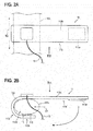
- Figs. 2A and 2B schematically illustrate the configuration of the probe 11.
- Fig. 2A shows the configuration as viewed in the direction of the arrow IIA in Fig. 2B.
- Fig. 2B illustrates the configuration as viewed in the direction of the arrow IIB in Fig. 2A .
- the probe 11 includes a light emitter 111, a light detector 112, and a support member 113.
- the light emitter 111 is configured so as to emit a red light beam and an infrared light beam.
- the light emitter 111 is a semiconductor light emitting device configured to emit light beams of the predetermined wavelengths.
- the semiconductor light emitting device may be a light emitting diode (LED), a laser diode, or an organic EL device.
- the light detector 112 has a light-detecting surface which is configured to detect a light beam transmitted through or reflected from a living tissue of the subject.
- the light detector 112 is configured so as to output an intensity signal based on the intensity of the light beam which is received by the light-detecting surface.
- the volume of blood in the living tissue to which the probe 11 is attached is changed by the pulsation of the subject. Therefore, the intensity of the light beam which is received by the light-detecting surface is changed, and also the intensity signal which is output from the light detector 112 is changed.
- the light detector 112 is an optical sensor having a sensitivity to the above-described predetermined wavelengths.
- the optical sensor may be a photodiode, a phototransistor, or a photoresistor.
- the light emitter 111 and the light detector 112 are supported by the support member 113 having a belt-like shape.
- the support member 113 has a hook surface 113a and loop surface 113b which form a hook and loop fastener.
- the probe 11 is configured so as to be used while the support member is wound around the hand finger 100.
- the hook surface 113a is fixed at an adequate position of the loop surface 113b, thereby the light emitter 111 and the light detector 112 are closely contacted with the hand finger 100.
- the sensor 10 further includes a cable 13.
- One end of the cable 13 is connected to the probe 11.
- the other end of the cable 13 is to be connected to a vital sign measurement apparatus which is not shown in the drawings.
- the cable 13 may include a power supply line for supplying an electric power to the light emitter 111 and the light detector 112, a signal line for transmitting the intensity signal output from the light detector 112, and the like.
- the cable 13 may be inseparably integrated with the probe 11, or attachable to and detachable from the probe 11.
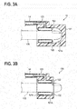
- Fig. 3A is a sectional view schematically illustrating the configuration of the cuff 12.
- the cuff 12 includes a case 121, an annular bag member 122, and an air passage 123.
- the case 121 has a bottomed hole 121a.
- the bag member 122 is accommodated in the hole 121a.
- the outer circumferential surface of the bag member 122 is fixed to the inner circumferential surface of the hole 121a.
- the air passage 123 communicates with the interior of the bag member 122.
- the hand finger 100 of the subject is inserted into the hole 121a. At this time, the inner circumferential surface of the bag member 122 surrounds the hand finger 100.
- the sensor 10 further includes a tube 14. As shown in Fig. 3A , one end of the tube 14 is connected to the air passage 123 of the cuff 12. The other end of the tube 14 is to be connected to the vital sign measurement apparatus which is not shown in the drawings.
- the tube 14 may be inseparably integrated with the cuff 12, or attachable to and detachable from the cuff 12.
- the tube 14 is used for supplying the air to the cuff 12. Specifically, the amount of the air which is supplied to the interior of the bag member 122 through the air passage 123 is adjusted based on a blood pressure measurement operation in the vital sign measurement apparatus. This causes the force with which the hand finger 100 is compressed by the bag member 122 in order to acquire the the non-invasive blood pressure of the subject, to be adjusted.
- the probe 11 is attached to a root portion 100a of the hand finger 100.
- the shape and dimensions of the probe 11 which has been described with reference to Fig. 2 are configured so that the probe is attached to the root portion 100a (an example of the first portion of the digit) of the hand finger 100.
- the cuff 12 is attached to a fingertip portion 100b of the hand finger 100.
- the shape and dimensions of the cuff 12 which has been described with reference to Fig. 3A are configured so that the cuff is attached to the fingertip portion 100b (an example of the second portion of the digit) of the hand finger 100.
- the fingertip portion 100b is defined as a portion which is located on the periphery side with respect to the root portion 100a.
- both the probe 11 for acquiring the arterial oxygen saturation of the subject, and the cuff 12 for acquiring the non-invasive blood pressure of the subject are attached to the hand finger 100 of the subject.
- the acquisition of the arterial oxygen saturation of the subject by the probe 11 is performed based on a volume change of blood that is caused by pulsation of the subject in the hand finger 100 to which the probe 11 is attached.
- the portion of the hand finger 100 to which the cuff 12 is attached is located on the periphery side with respect to the portion of the hand finger 100 to which the probe 11 is attached. Even when the bag member 122 of the cuff 12 compresses the fingertip portion 100b to acquire the non-invasive blood pressure, the pulsation of the artery in the root portion 100a which is necessary for the probe 11 to acquire the arterial oxygen saturation is not inhibited. In the case where measurements of the arterial oxygen saturation and the non-invasive blood pressure are simultaneously performed on the subject, decrease in the accuracy of the acquired arterial oxygen saturation is avoidable, and moreover the arterial oxygen saturation can be continuously measured.
- the cuff 12 includes the case 121 in which the bottomed hole 121a is formed.
- the hand finger 100 of the subject is to be inserted into the bottomed hole 121a.
- a configuration such as a cuff 12A of a modification shown in Fig. 3B may be used.
- the cuff 12A has a case 121A.
- the case 121A has a through hole 121b through which the fingertip of the hand finger 100 of the subject is passable.
- Components which are substantially identical with those of the sensor 10 of the cuff 12 are denoted by the same reference numerals.
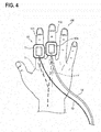
- Fig. 4 illustrates a state where a sensor 20 of a second embodiment is attached to the hand finger 100 of the subject.
- Components which are substantially identical with those of the sensor 10 of the first embodiment are denoted by the same reference numerals, and repeated description is omitted.
- the sensor 20 includes the probe 11 and the cuff 12A.
- the hand finger 100 of the subject includes the index finger 101 and the middle finger 102.
- the probe 11 is attached to the index finger 101 (an example of the first digit) of the subject.
- the cuff 12A is attached to the middle finger 102 (an example of the second digit) of the subject.
- both the probe 11 for acquiring the arterial oxygen saturation of the subject, and the cuff 12A for acquiring the non-invasive blood pressure of the subject are attached to the hand finger 100 of the subject.
- the acquisition of the arterial oxygen saturation of the subject by the probe 11 is performed based on a volume change of blood that is caused by pulsation of the subject in the hand finger 100 to which the probe 11 is attached.
- the probe 11 and the cuff 12A are attached to the different fingers, and therefore respectively placed above different peripheral blood vessels V. Even when the bag member 122 of the cuff 12A compresses the peripheral blood vessel in the middle finger 102 to acquire the non-invasive blood pressure, the pulsation of the artery in the index finger 101 which is necessary for the probe 11 to acquire the arterial oxygen saturation is not inhibited. In the case where measurements of the arterial oxygen saturation and the non-invasive blood pressure are simultaneously performed on the subject, decrease of the accuracy of the acquired arterial oxygen saturation is avoidable, and moreover the arterial oxygen saturation can be continuously measured.
- the probe 11 is attached to the index finger 101, and the cuff 12A is attached to the middle finger 102.
- the probe 11 and the cuff 12A can be attached to any fingers of the hand as far as the hand fingers to which the probe and the cuff are to be attached are different from each other.
- the cuff 12 shown in Fig. 3A may be used.
- the support member 113 of the probe 11 defines a space 113d having an opening 113c.
- the hand finger 100 can enter the space 113d from the opening 113c in a direction D1.
- the direction D1 is a direction intersecting with a direction D2 which is indicated in Fig. 2A , and along which the hand finger 100 extends.
- the work of attaching the probe 11 to the hand finger 100 can be facilitated.
- the cuff 12 is attached on the periphery side with respect to the probe 11 as in the example shown in Fig. 1 , particularly, the effect is remarkable.
- attachment of the probe 11 it is not necessary to consider the attachment sequence with respect to the cuff 12, or to once detach the cuff 12.
- the support member 113 has a first support portion 113e and a second support portion 113f.
- the first support portion 113e includes a part which supports at least the light emitter 111 and the light detector 112.
- the second support portion 113f includes at least a part for fixing the first support portion 113e to the hand finger 100.
- the second support portion 113f has a flexibility which is higher than that of the first support portion 113e. In other words, the first support portion 113e is more robust than the second support portion 113f.
- the light emitter 111 and the light detector 112 are supported by the more robust part, and therefore positional displacement of the light emitter 111 and the light detector 112 with respect to the hand finger 100 is easily reduced.
- the first support portion 113e is fixed to the hand finger 100 by the second support portion 113f which is more flexible. Consequently, the light emitter 111 and the light detector 112 can be closely attached to the hand finger. Therefore, the accuracy of the acquired arterial oxygen saturation can be improved.
- At least the first support portion 113e may be formed by a shape-memory material such as a shape-memory resin, a shape-memory alloy, or a shape-memory ceramic.
- the temperature functioning as the reference for shape memory may be ordinary temperature or body temperature.
- the space 113d which is defined by the support member 113 can be maintained to have a shape which is adequate for receiving the hand finger 100. Consequently, the light emitter 111 and the light detector 112 can be closely attached the hand finger 100. Therefore, the accuracy of the acquired arterial oxygen saturation can be improved.
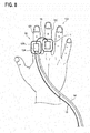
- Fig. 5 illustrates a state where a sensor 30 of a third embodiment is attached to the hand finger 100 of the subject.
- Components which are substantially identical with those of the sensor 10 of the first embodiment are denoted by the same reference numerals, and repeated description is omitted.
- the sensor 30 includes a probe 11A and the cuff 12.
- the probe 11A is a device for acquiring the arterial oxygen saturation of the subject.
- Figs. 6A and 6B schematically illustrate the configuration of the probe 11A.
- Fig. 6A illustrates the configuration as viewed in the direction of the arrow VIA in Fig. 6B.
- Fig. 6B illustrates the configuration as viewed in the direction of the arrow VIB in Fig. 6A .
- the probe 11A includes a support member 113A.
- the support member 113A includes a tube support portion 113g.
- the tube support portion 113g supports the tube 14 for supplying the air to the cuff 12.
- the tube support portion 113g may be structured so as to be detachable from the support member 113A by forming a hook surface which forms a hook and loop fastener, on a surface of the tube support portion 113g that is opposed to the loop surface 113b of the support member 113A.
- the probe 11A which is to be attached to the hand finger 100 in order to acquire the arterial oxygen saturation of the subject may be caused to function as a fixing device for the tube 14 connected to the cuff 12. Therefore, the drawn-out directions of the cable 13 and tube 14 which are drawn out from different places of the hand 100 can be easily aligned with each other. In the case where measurements of the arterial oxygen saturation and the non-invasive blood pressure are simultaneously performed on the subject, botheration which is applied to both the subject and the medical person can be further reduced.
- the tube support portion 113g may be immovable with respect to the tube 14, or slidable along the tube 14. In the latter case, the attachment position of the probe 11A can be appropriately adjusted while maintaining the integrality with the cuff 12. Therefore, decrease of the accuracy of the acquired arterial oxygen saturation is avoidable.
- Fig. 7 illustrates a state where a sensor 40 of a fourth embodiment is attached to the hand finger 100 of the subject.
- Components which are substantially identical with those of the sensor 20 of the second embodiment and the sensor 30 of the third embodiment are denoted by the same reference numerals, and repeated description is omitted.
- the sensor 40 includes the probe 11A and the cuff 12A.
- the tube support portion 113g of the probe 11a supports the tube 14 for supplying the air to the cuff 12A.
- the probe 11A which is to be attached to the hand finger 100 in order to acquire the arterial oxygen saturation of the subject may be caused to function as a fixing device for the tube 14 connected to the cuff 12A. Therefore, the drawn-out directions of the cable 13 and tube 14 which are drawn out from different hand fingers can be easily aligned with each other. In the case where measurements of the arterial oxygen saturation and the non-invasive blood pressure are simultaneously performed on the subject, therefore, botheration which is applied to both the subject and the medical person can be further reduced.
- Fig. 8 illustrates a state where a sensor 50 of a fifth embodiment is attached to the hand finger 100 of the subject.
- Components which are substantially identical with those of the sensor 10 of the first embodiment are denoted by the same reference numerals, and repeated description is omitted.
- the sensor 50 includes the probe 11 and a cuff 12B.
- the probe 11 is attached to the middle finger 102 (an example of the first digit) of the subject, and the cuff 12B is attached to the index finger 101 (an example of the second digit) of the subject.
- the cuff 12B is a device for acquiring the non-invasive blood pressure of the subject.
- the basic configuration of the cuff 12B may be similar to that of the cuff 12 shown in Fig. 3A or that of the cuff 12A shown in Fig. 3B .
- the cuff 12B is different from the cuff 12 and the cuff 12A in that the cuff 12B includes a cable support portion 124.
- the cable support portion 124 supports the cable 13 connected to the probe 11.
- the cuff 12B which is to be attached to the hand finger 100 in order to acquire the non-invasive blood pressure may be used as a fixing device for the cable 13 connected to the probe 11. Therefore, the drawn-out directions of the cable 13 and tube 14 which are drawn out from different fingers can be easily aligned with each other. In the case where measurements of the arterial oxygen saturation and the non-invasive blood pressure are simultaneously performed on the subject, therefore, botheration which is applied to both the subject and the medical person can be further reduced.
- the probe for acquiring the arterial oxygen saturation, and the cuff for acquiring the non-invasive blood pressure are attached to a hand finger(s) of the subject.
- the probe and the cuff may be configured so as to be attached to toes of the foot of the subject.
- the probe is used for acquiring the arterial oxygen saturation.
- the probe may have a configuration for acquiring a blood light absorber, such as the concentration of carboxyhemoglobin, methemoglobin, or the like.
- the light emitter 111 is configured so as to emit a red light beam and an infrared light beam.
- the light emitter 111 may be configured so as to further emit a blue light beam, a green light beam, an orange light beam, a red-orange light beam, or the like.
Landscapes
- Health & Medical Sciences (AREA)
- Life Sciences & Earth Sciences (AREA)
- Physics & Mathematics (AREA)
- General Health & Medical Sciences (AREA)
- Veterinary Medicine (AREA)
- Engineering & Computer Science (AREA)
- Biomedical Technology (AREA)
- Heart & Thoracic Surgery (AREA)
- Medical Informatics (AREA)
- Molecular Biology (AREA)
- Surgery (AREA)
- Animal Behavior & Ethology (AREA)
- Biophysics (AREA)
- Public Health (AREA)
- Pathology (AREA)
- Vascular Medicine (AREA)
- Cardiology (AREA)
- Spectroscopy & Molecular Physics (AREA)
- Optics & Photonics (AREA)
- Dentistry (AREA)
- Ophthalmology & Optometry (AREA)
- Physiology (AREA)
- Measurement Of The Respiration, Hearing Ability, Form, And Blood Characteristics Of Living Organisms (AREA)
- Measuring Pulse, Heart Rate, Blood Pressure Or Blood Flow (AREA)
Abstract
Description
- The present invention relates to a sensor including a probe for acquiring the blood light absorber concentration in a subject and a cuff for acquiring the non-invasive blood pressure of the subject.
-
JP-A-2007-029702 - In the case where measurements of the blood light absorber concentration and the non-invasive blood pressure are to be simultaneously performed on a subject, a cuff for acquiring the non-invasive blood pressure is usually wrapped around the upper arm of the subject.
- In this case, a cable for a signal from the probe is drawn out from the fingertip portion of the subject, and a tube for supplying the air to the cuff is drawn out from the upper arm portion of the subject. The situation where the cable and the tube are drawn out from the separate body places of the subject may provide both the subject and the medical person with botheration.
- It is an object of the invention to, in the case where measurements of the blood light absorber concentration and the non-invasive blood pressure are simultaneously performed on a subject, reduce botheration which is applied to both the subject and the medical person.
- According to an aspect of the invention, a sensor includes:
- a probe that acquires a blood light absorber concentration in a subject; and
- a cuff that acquires a non-invasive blood pressure of the subject,
- wherein the probe is configured to be attached to a first portion of a digit of the subject, and
- the cuff is configured to be attached to a second portion of the digit, the second portion being located on a periphery side with respect to the first portion.
- According to the above configuration, both the probe for acquiring the blood light absorber concentration in the subject, and the cuff for acquiring the non-invasive blood pressure of the subject are attached to the digit of the subject. Therefore, both a cable which is connected to the probe, and a tube which is connected to the cuff can be drawn out from the digit of the subject. It is possible to avoid a situation where the cable and the tube are drawn out from separate body places of the subject. In the case where measurements of the blood light absorber concentration and the non-invasive blood pressure are simultaneously performed on the subject, botheration which is applied to both the subject and the medical person can be reduced.
- The acquisition of the blood light absorber concentration in the subject by the probe is performed based on a volume change of blood that is caused by pulsation of the subject in the digit to which the probe is attached. According to the configuration, the second portion of the digit to which the cuff is attached is located on the periphery side with respect to the first portion to which the probe is attached. Even when the cuff compresses the second portion of the digit to acquire the non-invasive blood pressure, the pulsation of the artery in the first portion which is necessary for the probe to acquire the blood light absorber concentration is not inhibited. In the case where measurements of the blood light absorber concentration and the non-invasive blood pressure are simultaneously performed on the subject, decrease in the accuracy of the acquired blood light absorber concentration is avoidable, and moreover the blood light absorber concentration can be continuously measured.
- According to an aspect of the invention, a sensor includes:
- a probe that acquires a blood light absorber concentration in a subject; and
- a cuff that acquires a non-invasive blood pressure of the subject,
- wherein the probe is configured to be attached to a first digit of the subject, and
- the cuff is configured to be attached to a second digit of the subject.
- According to the configuration, both the probe for acquiring the blood light absorber concentration in the subject, and the cuff for acquiring the non-invasive blood pressure of the subject are attached to the digits of the subject. Therefore, both a cable which is connected to the probe, and a tube which is connected to the cuff can be drawn out from the hand or foot of the subject. It is possible to avoid a situation where the cable and the tube are drawn out from separate body places of the subject. In the case where measurements of the blood light absorber concentration and the non-invasive blood pressure are simultaneously performed on the subject, botheration which is applied to both the subject and the medical person can be reduced.
- The acquisition of the blood light absorber concentration in the subject by the probe is performed based on a volume change of blood that is caused by pulsation of the subject in the digit to which the probe is attached. According to the configuration, the probe and the cuff are attached to different digits, and therefore placed to different peripheral blood vessels from each other. Even when the cuff compresses peripheral blood vessels in the second digit to acquire the non-invasive blood pressure, the pulsation of the artery in the first digit which is necessary for the probe to acquire the blood light absorber concentration is not inhibited. In the case where measurements of the blood light absorber concentration and the non-invasive blood pressure are simultaneously performed on the subject, decrease of the accuracy of the acquired blood light absorber concentration is avoidable, and moreover the blood light absorber concentration can be continuously measured.
-
-
Fig. 1 illustrates an attachment state of a sensor in a first embodiment to a subject. -
Figs. 2A and 2B illustrate the configuration of a probe of the sensor ofFig. 1 . -
Figs. 3A and 3B illustrate the configuration of a cuff of the sensor ofFig. 1 . -
Fig. 4 illustrates an attachment state of a sensor in a second embodiment to the subject. -
Fig. 5 illustrates an attachment state of a sensor in a third embodiment to the subject. -
Figs. 6A and 6B illustrate the configuration of a probe of the sensor ofFig. 5 . -
Fig. 7 illustrates an attachment state of a sensor in a fourth embodiment to the subject. -
Fig. 8 illustrates an attachment state of a sensor in a fifth embodiment to the subject. - Hereinafter, embodiment examples will be described in detail with reference to the accompanying drawings.
Fig. 1 illustrates a state in which asensor 10 of a first embodiment is attached to ahand finger 100 of a subject. - The
sensor 10 includes aprobe 11 and acuff 12. Theprobe 11 is a device for acquiring the arterial oxygen saturation (an example of the blood light absorber concentration) of the subject. Thecuff 12 is a device for acquiring the non-invasive blood pressure of the subject. -
Figs. 2A and 2B schematically illustrate the configuration of theprobe 11.Fig. 2A shows the configuration as viewed in the direction of the arrow IIA inFig. 2B. Fig. 2B illustrates the configuration as viewed in the direction of the arrow IIB inFig. 2A . - As shown in
Fig. 2B , theprobe 11 includes alight emitter 111, alight detector 112, and asupport member 113. - The
light emitter 111 is configured so as to emit a red light beam and an infrared light beam. For example, thelight emitter 111 is a semiconductor light emitting device configured to emit light beams of the predetermined wavelengths. The semiconductor light emitting device may be a light emitting diode (LED), a laser diode, or an organic EL device. - The
light detector 112 has a light-detecting surface which is configured to detect a light beam transmitted through or reflected from a living tissue of the subject. Thelight detector 112 is configured so as to output an intensity signal based on the intensity of the light beam which is received by the light-detecting surface. The volume of blood in the living tissue to which theprobe 11 is attached is changed by the pulsation of the subject. Therefore, the intensity of the light beam which is received by the light-detecting surface is changed, and also the intensity signal which is output from thelight detector 112 is changed. - For example, the
light detector 112 is an optical sensor having a sensitivity to the above-described predetermined wavelengths. The optical sensor may be a photodiode, a phototransistor, or a photoresistor. - The
light emitter 111 and thelight detector 112 are supported by thesupport member 113 having a belt-like shape. Thesupport member 113 has ahook surface 113a andloop surface 113b which form a hook and loop fastener. Theprobe 11 is configured so as to be used while the support member is wound around thehand finger 100. Thehook surface 113a is fixed at an adequate position of theloop surface 113b, thereby thelight emitter 111 and thelight detector 112 are closely contacted with thehand finger 100. - The
sensor 10 further includes acable 13. One end of thecable 13 is connected to theprobe 11. The other end of thecable 13 is to be connected to a vital sign measurement apparatus which is not shown in the drawings. Thecable 13 may include a power supply line for supplying an electric power to thelight emitter 111 and thelight detector 112, a signal line for transmitting the intensity signal output from thelight detector 112, and the like. Thecable 13 may be inseparably integrated with theprobe 11, or attachable to and detachable from theprobe 11. -
Fig. 3A is a sectional view schematically illustrating the configuration of thecuff 12. Thecuff 12 includes acase 121, anannular bag member 122, and anair passage 123. Thecase 121 has a bottomedhole 121a. Thebag member 122 is accommodated in thehole 121a. The outer circumferential surface of thebag member 122 is fixed to the inner circumferential surface of thehole 121a. Theair passage 123 communicates with the interior of thebag member 122. - When the
cuff 12 is used, thehand finger 100 of the subject is inserted into thehole 121a. At this time, the inner circumferential surface of thebag member 122 surrounds thehand finger 100. - As shown in
Fig. 1 , thesensor 10 further includes atube 14. As shown inFig. 3A , one end of thetube 14 is connected to theair passage 123 of thecuff 12. The other end of thetube 14 is to be connected to the vital sign measurement apparatus which is not shown in the drawings. Thetube 14 may be inseparably integrated with thecuff 12, or attachable to and detachable from thecuff 12. - The
tube 14 is used for supplying the air to thecuff 12. Specifically, the amount of the air which is supplied to the interior of thebag member 122 through theair passage 123 is adjusted based on a blood pressure measurement operation in the vital sign measurement apparatus. This causes the force with which thehand finger 100 is compressed by thebag member 122 in order to acquire the the non-invasive blood pressure of the subject, to be adjusted. - As shown in
Fig. 1 , theprobe 11 is attached to aroot portion 100a of thehand finger 100. In other words, the shape and dimensions of theprobe 11 which has been described with reference toFig. 2 are configured so that the probe is attached to theroot portion 100a (an example of the first portion of the digit) of thehand finger 100. - On the other hand, the
cuff 12 is attached to afingertip portion 100b of thehand finger 100. In other words, the shape and dimensions of thecuff 12 which has been described with reference toFig. 3A are configured so that the cuff is attached to thefingertip portion 100b (an example of the second portion of the digit) of thehand finger 100. Thefingertip portion 100b is defined as a portion which is located on the periphery side with respect to theroot portion 100a. - In the embodiment, both the
probe 11 for acquiring the arterial oxygen saturation of the subject, and thecuff 12 for acquiring the non-invasive blood pressure of the subject are attached to thehand finger 100 of the subject. This allows both thecable 13 which is connected to theprobe 11, and thetube 14 which is connected to thecuff 12, to be drawn out from thehand finger 100 of the subject as shown inFig. 1 . It is possible to avoid a situation where the cable and the tube are drawn out from separate body places of the subject. In the case where measurements of the arterial oxygen saturation and the non-invasive blood pressure are simultaneously performed on the subject, therefore, botheration which is applied to both the subject and the medical person can be reduced. - As described above, the acquisition of the arterial oxygen saturation of the subject by the
probe 11 is performed based on a volume change of blood that is caused by pulsation of the subject in thehand finger 100 to which theprobe 11 is attached. In the embodiment, the portion of thehand finger 100 to which thecuff 12 is attached is located on the periphery side with respect to the portion of thehand finger 100 to which theprobe 11 is attached. Even when thebag member 122 of thecuff 12 compresses thefingertip portion 100b to acquire the non-invasive blood pressure, the pulsation of the artery in theroot portion 100a which is necessary for theprobe 11 to acquire the arterial oxygen saturation is not inhibited. In the case where measurements of the arterial oxygen saturation and the non-invasive blood pressure are simultaneously performed on the subject, decrease in the accuracy of the acquired arterial oxygen saturation is avoidable, and moreover the arterial oxygen saturation can be continuously measured. - In the embodiment, as shown in
Fig. 3A , thecuff 12 includes thecase 121 in which the bottomedhole 121a is formed. Thehand finger 100 of the subject is to be inserted into the bottomedhole 121a. A configuration such as acuff 12A of a modification shown inFig. 3B may be used. Thecuff 12A has acase 121A. Thecase 121A has a throughhole 121b through which the fingertip of thehand finger 100 of the subject is passable. Components which are substantially identical with those of thesensor 10 of thecuff 12 are denoted by the same reference numerals. -
Fig. 4 illustrates a state where asensor 20 of a second embodiment is attached to thehand finger 100 of the subject. Components which are substantially identical with those of thesensor 10 of the first embodiment are denoted by the same reference numerals, and repeated description is omitted. - The
sensor 20 includes theprobe 11 and thecuff 12A. Thehand finger 100 of the subject includes theindex finger 101 and themiddle finger 102. Theprobe 11 is attached to the index finger 101 (an example of the first digit) of the subject. Thecuff 12A is attached to the middle finger 102 (an example of the second digit) of the subject. - Also in the embodiment, both the
probe 11 for acquiring the arterial oxygen saturation of the subject, and thecuff 12A for acquiring the non-invasive blood pressure of the subject are attached to thehand finger 100 of the subject. This allows both thecable 13 which is connected to theprobe 11, and thetube 14 which is connected to thecuff 12A, to be drawn out from the hand of the subject as shown inFig. 4 . It is possible to avoid a situation where the cable and the tube are drawn out from separate body places of the subject. In the case where measurements of the arterial oxygen saturation and the non-invasive blood pressure are simultaneously performed on the subject, therefore, botheration which is applied to both the subject and the medical person can be reduced. - As described above, the acquisition of the arterial oxygen saturation of the subject by the
probe 11 is performed based on a volume change of blood that is caused by pulsation of the subject in thehand finger 100 to which theprobe 11 is attached. In the embodiment, theprobe 11 and thecuff 12A are attached to the different fingers, and therefore respectively placed above different peripheral blood vessels V. Even when thebag member 122 of thecuff 12A compresses the peripheral blood vessel in themiddle finger 102 to acquire the non-invasive blood pressure, the pulsation of the artery in theindex finger 101 which is necessary for theprobe 11 to acquire the arterial oxygen saturation is not inhibited. In the case where measurements of the arterial oxygen saturation and the non-invasive blood pressure are simultaneously performed on the subject, decrease of the accuracy of the acquired arterial oxygen saturation is avoidable, and moreover the arterial oxygen saturation can be continuously measured. - In the embodiment, the
probe 11 is attached to theindex finger 101, and thecuff 12A is attached to themiddle finger 102. However, theprobe 11 and thecuff 12A can be attached to any fingers of the hand as far as the hand fingers to which the probe and the cuff are to be attached are different from each other. In place of thecuff 12A, thecuff 12 shown inFig. 3A may be used. - In the above-described embodiments, as shown in
Fig. 2B , thesupport member 113 of theprobe 11 defines aspace 113d having anopening 113c. When theprobe 11 is attached to thehand finger 100 of the subject, thehand finger 100 can enter thespace 113d from theopening 113c in a direction D1. The direction D1 is a direction intersecting with a direction D2 which is indicated inFig. 2A , and along which thehand finger 100 extends. - According to the configuration, in the case where measurements of the arterial oxygen saturation and the non-invasive blood pressure are simultaneously performed on the subject, the work of attaching the
probe 11 to thehand finger 100 can be facilitated. In the case where thecuff 12 is attached on the periphery side with respect to theprobe 11 as in the example shown inFig. 1 , particularly, the effect is remarkable. In attachment of theprobe 11, it is not necessary to consider the attachment sequence with respect to thecuff 12, or to once detach thecuff 12. - As shown in
Fig. 2B , thesupport member 113 has afirst support portion 113e and asecond support portion 113f. Thefirst support portion 113e includes a part which supports at least thelight emitter 111 and thelight detector 112. Thesecond support portion 113f includes at least a part for fixing thefirst support portion 113e to thehand finger 100. Thesecond support portion 113f has a flexibility which is higher than that of thefirst support portion 113e. In other words, thefirst support portion 113e is more robust than thesecond support portion 113f. - According to the configuration, the
light emitter 111 and thelight detector 112 are supported by the more robust part, and therefore positional displacement of thelight emitter 111 and thelight detector 112 with respect to thehand finger 100 is easily reduced. On the other hand, thefirst support portion 113e is fixed to thehand finger 100 by thesecond support portion 113f which is more flexible. Consequently, thelight emitter 111 and thelight detector 112 can be closely attached to the hand finger. Therefore, the accuracy of the acquired arterial oxygen saturation can be improved. - In the
support member 113, at least thefirst support portion 113e may be formed by a shape-memory material such as a shape-memory resin, a shape-memory alloy, or a shape-memory ceramic. The temperature functioning as the reference for shape memory may be ordinary temperature or body temperature. - According to the configuration, the
space 113d which is defined by thesupport member 113 can be maintained to have a shape which is adequate for receiving thehand finger 100. Consequently, thelight emitter 111 and thelight detector 112 can be closely attached thehand finger 100. Therefore, the accuracy of the acquired arterial oxygen saturation can be improved. -
Fig. 5 illustrates a state where asensor 30 of a third embodiment is attached to thehand finger 100 of the subject. Components which are substantially identical with those of thesensor 10 of the first embodiment are denoted by the same reference numerals, and repeated description is omitted. - The
sensor 30 includes aprobe 11A and thecuff 12. Theprobe 11A is a device for acquiring the arterial oxygen saturation of the subject. -
Figs. 6A and 6B schematically illustrate the configuration of theprobe 11A.Fig. 6A illustrates the configuration as viewed in the direction of the arrow VIA inFig. 6B. Fig. 6B illustrates the configuration as viewed in the direction of the arrow VIB inFig. 6A . - The
probe 11A includes asupport member 113A. Thesupport member 113A includes atube support portion 113g. Thetube support portion 113g supports thetube 14 for supplying the air to thecuff 12. Thetube support portion 113g may be structured so as to be detachable from thesupport member 113A by forming a hook surface which forms a hook and loop fastener, on a surface of thetube support portion 113g that is opposed to theloop surface 113b of thesupport member 113A. - According to the configuration, as shown in
Fig. 5 , theprobe 11A which is to be attached to thehand finger 100 in order to acquire the arterial oxygen saturation of the subject may be caused to function as a fixing device for thetube 14 connected to thecuff 12. Therefore, the drawn-out directions of thecable 13 andtube 14 which are drawn out from different places of thehand 100 can be easily aligned with each other. In the case where measurements of the arterial oxygen saturation and the non-invasive blood pressure are simultaneously performed on the subject, botheration which is applied to both the subject and the medical person can be further reduced. - The
tube support portion 113g may be immovable with respect to thetube 14, or slidable along thetube 14. In the latter case, the attachment position of theprobe 11A can be appropriately adjusted while maintaining the integrality with thecuff 12. Therefore, decrease of the accuracy of the acquired arterial oxygen saturation is avoidable. -
Fig. 7 illustrates a state where asensor 40 of a fourth embodiment is attached to thehand finger 100 of the subject. Components which are substantially identical with those of thesensor 20 of the second embodiment and thesensor 30 of the third embodiment are denoted by the same reference numerals, and repeated description is omitted. - The
sensor 40 includes theprobe 11A and thecuff 12A. Thetube support portion 113g of the probe 11a supports thetube 14 for supplying the air to thecuff 12A. - According to the configuration, the
probe 11A which is to be attached to thehand finger 100 in order to acquire the arterial oxygen saturation of the subject may be caused to function as a fixing device for thetube 14 connected to thecuff 12A. Therefore, the drawn-out directions of thecable 13 andtube 14 which are drawn out from different hand fingers can be easily aligned with each other. In the case where measurements of the arterial oxygen saturation and the non-invasive blood pressure are simultaneously performed on the subject, therefore, botheration which is applied to both the subject and the medical person can be further reduced. -
Fig. 8 illustrates a state where asensor 50 of a fifth embodiment is attached to thehand finger 100 of the subject. Components which are substantially identical with those of thesensor 10 of the first embodiment are denoted by the same reference numerals, and repeated description is omitted. - The
sensor 50 includes theprobe 11 and acuff 12B. Theprobe 11 is attached to the middle finger 102 (an example of the first digit) of the subject, and thecuff 12B is attached to the index finger 101 (an example of the second digit) of the subject. - The
cuff 12B is a device for acquiring the non-invasive blood pressure of the subject. The basic configuration of thecuff 12B may be similar to that of thecuff 12 shown inFig. 3A or that of thecuff 12A shown inFig. 3B . Thecuff 12B is different from thecuff 12 and thecuff 12A in that thecuff 12B includes acable support portion 124. Thecable support portion 124 supports thecable 13 connected to theprobe 11. - According to the configuration, the
cuff 12B which is to be attached to thehand finger 100 in order to acquire the non-invasive blood pressure may be used as a fixing device for thecable 13 connected to theprobe 11. Therefore, the drawn-out directions of thecable 13 andtube 14 which are drawn out from different fingers can be easily aligned with each other. In the case where measurements of the arterial oxygen saturation and the non-invasive blood pressure are simultaneously performed on the subject, therefore, botheration which is applied to both the subject and the medical person can be further reduced. - The above-described embodiments is for facilitating understanding of the invention, and do not limit the invention. It is obvious that the configuration may be changed or improved without deviation from the point of the invention, and its equivalents are included within the scope of the invention.
- In the above-described embodiments, the probe for acquiring the arterial oxygen saturation, and the cuff for acquiring the non-invasive blood pressure are attached to a hand finger(s) of the subject. However, the probe and the cuff may be configured so as to be attached to toes of the foot of the subject.
- In the above-described embodiments, the probe is used for acquiring the arterial oxygen saturation. However, the probe may have a configuration for acquiring a blood light absorber, such as the concentration of carboxyhemoglobin, methemoglobin, or the like.
- In the above-described embodiments, the
light emitter 111 is configured so as to emit a red light beam and an infrared light beam. However, thelight emitter 111 may be configured so as to further emit a blue light beam, a green light beam, an orange light beam, a red-orange light beam, or the like.
Claims (7)
- A sensor comprising:a probe that acquires a blood light absorber concentration in a subject; anda cuff that acquires a non-invasive blood pressure of the subject,wherein the probe is configured to be attached to a first portion of a digit of the subject, andthe cuff is configured to be attached to a second portion of the digit, the second portion being located on a periphery side with respect to the first portion.
- A sensor comprising:a probe that acquires a blood light absorber concentration in a subject; anda cuff that acquires a non-invasive blood pressure of the subject,wherein the probe is configured to be attached to a first digit of the subject, andthe cuff is configured to be attached to a second digit of the subject.
- The sensor according to claim 1 or 2 further comprising a tube that supplies air to the cuff,
wherein the probe includes:a light emitter;a light detector; anda support member that supports the light emitter and the light detector, andthe tube is supported by the support member. - The sensor according to claim 2 further comprising a cable that is connected to the probe,
wherein the cable is supported by the cuff. - The sensor according to any one of claims 1 to 4, wherein
the probe includes:a light emitter;a light detector; anda support member that supports the light emitter and the light detector, andthe support member has a shape which is curved to have an open portion. - The sensor according to claim 5, wherein
the support member includes:a first support portion that supports the light emitter and the light detector; anda second support portion that is higher in flexibility than the first support portion, and that is used for fixing the first support portion to the first portion of the digit or the first digit. - The sensor according to claim 5 or 6, wherein the support member is made of a shape-memory material.
Applications Claiming Priority (1)
| Application Number | Priority Date | Filing Date | Title |
|---|---|---|---|
| JP2017063083A JP6904746B2 (en) | 2017-03-28 | 2017-03-28 | Sensor |
Publications (1)
| Publication Number | Publication Date |
|---|---|
| EP3381357A1 true EP3381357A1 (en) | 2018-10-03 |
Family
ID=61906603
Family Applications (1)
| Application Number | Title | Priority Date | Filing Date |
|---|---|---|---|
| EP18164208.3A Withdrawn EP3381357A1 (en) | 2017-03-28 | 2018-03-27 | Sensor |
Country Status (3)
| Country | Link |
|---|---|
| US (1) | US11045098B2 (en) |
| EP (1) | EP3381357A1 (en) |
| JP (1) | JP6904746B2 (en) |
Citations (5)
| Publication number | Priority date | Publication date | Assignee | Title |
|---|---|---|---|---|
| US3149628A (en) * | 1964-09-22 | Blood pressure detector | ||
| JPS62270133A (en) * | 1986-05-19 | 1987-11-24 | 山越 憲一 | Indirect lowest blood pressure measuring method by cuff vibration method |
| JPH09289977A (en) * | 1996-04-26 | 1997-11-11 | Nippon Koden Corp | Biological signal measurement sensor |
| JP2007029702A (en) | 2005-06-20 | 2007-02-08 | Nippon Seimitsu Sokki Kk | Fingertip clip of photoelectric biological information measuring device |
| US20150141849A1 (en) * | 2013-10-24 | 2015-05-21 | Nicolay Verwaltung Gmbh | Method and device for noninvasive blood pressure measurement |
Family Cites Families (8)
| Publication number | Priority date | Publication date | Assignee | Title |
|---|---|---|---|---|
| US5165416A (en) * | 1990-08-23 | 1992-11-24 | Colin Electronics Co., Ltd. | Continuous blood pressure monitoring system having a digital cuff calibration system and method |
| US6018673A (en) * | 1996-10-10 | 2000-01-25 | Nellcor Puritan Bennett Incorporated | Motion compatible sensor for non-invasive optical blood analysis |
| EP0934021A2 (en) * | 1996-10-24 | 1999-08-11 | Massachusetts Institute Of Technology | Patient monitoring finger ring sensor |
| IL124787A0 (en) * | 1998-06-07 | 1999-01-26 | Itamar Medical C M 1997 Ltd | Pressure applicator devices particularly useful for non-invasive detection of medical conditions |
| US7522948B2 (en) * | 2006-05-02 | 2009-04-21 | Nellcor Puritan Bennett Llc | Medical sensor and technique for using the same |
| US20120165688A1 (en) * | 2010-12-28 | 2012-06-28 | Yip Inc. | Wireless optical pulsimetry system for a healthcare environment |
| US8700116B2 (en) * | 2011-09-29 | 2014-04-15 | Covidien Lp | Sensor system with pressure application |
| US11134901B2 (en) * | 2016-03-30 | 2021-10-05 | Elfi-Tech Ltd. | Method and apparatus for optically measuring blood pressure |
-
2017
- 2017-03-28 JP JP2017063083A patent/JP6904746B2/en not_active Expired - Fee Related
-
2018
- 2018-03-26 US US15/935,335 patent/US11045098B2/en active Active
- 2018-03-27 EP EP18164208.3A patent/EP3381357A1/en not_active Withdrawn
Patent Citations (5)
| Publication number | Priority date | Publication date | Assignee | Title |
|---|---|---|---|---|
| US3149628A (en) * | 1964-09-22 | Blood pressure detector | ||
| JPS62270133A (en) * | 1986-05-19 | 1987-11-24 | 山越 憲一 | Indirect lowest blood pressure measuring method by cuff vibration method |
| JPH09289977A (en) * | 1996-04-26 | 1997-11-11 | Nippon Koden Corp | Biological signal measurement sensor |
| JP2007029702A (en) | 2005-06-20 | 2007-02-08 | Nippon Seimitsu Sokki Kk | Fingertip clip of photoelectric biological information measuring device |
| US20150141849A1 (en) * | 2013-10-24 | 2015-05-21 | Nicolay Verwaltung Gmbh | Method and device for noninvasive blood pressure measurement |
Non-Patent Citations (2)
| Title |
|---|
| ILIES C ET AL: "Investigation of the agreement of a continuous non-invasive arterial pressure device in comparison with invasive radial artery measurement.", BRITISH JOURNAL OF ANAESTHESIA FEB 2012, vol. 108, no. 2, February 2012 (2012-02-01), pages 202 - 210, XP002783092, ISSN: 1471-6771 * |
| M A LYEW ET AL: "Blood pressure measurement using oscillometric finger cuffs in children and young adults. A comparison with arm cuffs during general anaesthesia", ANAESTHESIA, 1 October 1994 (1994-10-01), England, pages 895 - 899, XP055492987, Retrieved from the Internet <URL:https://onlinelibrary.wiley.com/doi/pdf/10.1111/j.1365-2044.1994.tb04270.x> DOI: 10.1111/j.1365-2044.1994.tb04270.x * |
Also Published As
| Publication number | Publication date |
|---|---|
| JP6904746B2 (en) | 2021-07-21 |
| US11045098B2 (en) | 2021-06-29 |
| JP2018164602A (en) | 2018-10-25 |
| US20180279890A1 (en) | 2018-10-04 |
Similar Documents
| Publication | Publication Date | Title |
|---|---|---|
| US5080098A (en) | Non-invasive sensor | |
| US10058254B2 (en) | Systems and methods for optical sensor arrangements | |
| US9603559B2 (en) | Capillary refill time diagnostic apparatus and methods | |
| US10188329B2 (en) | Self-contained regional oximetry | |
| US10285599B2 (en) | Wearable hemodynamic sensor | |
| US8257274B2 (en) | Medical sensor and technique for using the same | |
| US8798703B2 (en) | Disposable and detachable sensor for continuous non-invasive arterial blood pressure monitoring | |
| US20180235489A1 (en) | Photoplethysmographic wearable blood pressure monitoring system and methods | |
| US12070333B2 (en) | Wearable device for sensing vital signs | |
| EP3583891B1 (en) | Apparatus and method for measuring bio-information | |
| CN107847190A (en) | For keeping the apparatus of biosensor | |
| US20210052223A1 (en) | Universal fingertip sensor | |
| EP3000388A1 (en) | Sensor and biological signal measuring system | |
| US20170027515A1 (en) | Non-Invasive Continuous Monitoring of Physiological Parameters | |
| JP2009082627A (en) | Biological information measuring device | |
| US20210307632A1 (en) | Noninvasive blood-pressure measuring device | |
| WO2006079862A2 (en) | Pulse oximeter and casing for anchoring a sensor | |
| US11045098B2 (en) | Sensor | |
| EP3117763B1 (en) | Probe | |
| US20180271424A1 (en) | Sensor | |
| JPWO2019181268A1 (en) | Biological information measuring device | |
| US12471792B2 (en) | Tapped light in a laser-based photoplethysmographic device | |
| KR20110037138A (en) | Oxygen saturation measuring device | |
| US20230172463A1 (en) | Non-invasive device for continuous hemodynamic monitoring utilizing a micro-laser | |
| TW201639529A (en) | Wearable physiological state detecting device |
Legal Events
| Date | Code | Title | Description |
|---|---|---|---|
| PUAI | Public reference made under article 153(3) epc to a published international application that has entered the european phase |
Free format text: ORIGINAL CODE: 0009012 |
|
| STAA | Information on the status of an ep patent application or granted ep patent |
Free format text: STATUS: THE APPLICATION HAS BEEN PUBLISHED |
|
| AK | Designated contracting states |
Kind code of ref document: A1 Designated state(s): AL AT BE BG CH CY CZ DE DK EE ES FI FR GB GR HR HU IE IS IT LI LT LU LV MC MK MT NL NO PL PT RO RS SE SI SK SM TR |
|
| AX | Request for extension of the european patent |
Extension state: BA ME |
|
| STAA | Information on the status of an ep patent application or granted ep patent |
Free format text: STATUS: REQUEST FOR EXAMINATION WAS MADE |
|
| 17P | Request for examination filed |
Effective date: 20190329 |
|
| RBV | Designated contracting states (corrected) |
Designated state(s): AL AT BE BG CH CY CZ DE DK EE ES FI FR GB GR HR HU IE IS IT LI LT LU LV MC MK MT NL NO PL PT RO RS SE SI SK SM TR |
|
| STAA | Information on the status of an ep patent application or granted ep patent |
Free format text: STATUS: EXAMINATION IS IN PROGRESS |
|
| 17Q | First examination report despatched |
Effective date: 20211207 |
|
| STAA | Information on the status of an ep patent application or granted ep patent |
Free format text: STATUS: THE APPLICATION IS DEEMED TO BE WITHDRAWN |
|
| 18D | Application deemed to be withdrawn |
Effective date: 20231220 |