EP3381338A1 - Appareil de cuisson par flux chauffant avec moyen de remuage - Google Patents
Appareil de cuisson par flux chauffant avec moyen de remuage Download PDFInfo
- Publication number
- EP3381338A1 EP3381338A1 EP18163786.9A EP18163786A EP3381338A1 EP 3381338 A1 EP3381338 A1 EP 3381338A1 EP 18163786 A EP18163786 A EP 18163786A EP 3381338 A1 EP3381338 A1 EP 3381338A1
- Authority
- EP
- European Patent Office
- Prior art keywords
- compartment
- cooking appliance
- appliance according
- cooking
- housing
- Prior art date
- Legal status (The legal status is an assumption and is not a legal conclusion. Google has not performed a legal analysis and makes no representation as to the accuracy of the status listed.)
- Granted
Links
Images

Classifications
-
- A—HUMAN NECESSITIES
- A47—FURNITURE; DOMESTIC ARTICLES OR APPLIANCES; COFFEE MILLS; SPICE MILLS; SUCTION CLEANERS IN GENERAL
- A47J—KITCHEN EQUIPMENT; COFFEE MILLS; SPICE MILLS; APPARATUS FOR MAKING BEVERAGES
- A47J37/00—Baking; Roasting; Grilling; Frying
- A47J37/04—Roasting apparatus with movably-mounted food supports or with movable heating implements; Spits
- A47J37/043—Roasting apparatus with movably-mounted food supports or with movable heating implements; Spits with food supports rotating about a vertical axis
-
- A—HUMAN NECESSITIES
- A47—FURNITURE; DOMESTIC ARTICLES OR APPLIANCES; COFFEE MILLS; SPICE MILLS; SUCTION CLEANERS IN GENERAL
- A47J—KITCHEN EQUIPMENT; COFFEE MILLS; SPICE MILLS; APPARATUS FOR MAKING BEVERAGES
- A47J27/00—Cooking-vessels
- A47J27/002—Construction of cooking-vessels; Methods or processes of manufacturing specially adapted for cooking-vessels
-
- A—HUMAN NECESSITIES
- A47—FURNITURE; DOMESTIC ARTICLES OR APPLIANCES; COFFEE MILLS; SPICE MILLS; SUCTION CLEANERS IN GENERAL
- A47J—KITCHEN EQUIPMENT; COFFEE MILLS; SPICE MILLS; APPARATUS FOR MAKING BEVERAGES
- A47J36/00—Parts, details or accessories of cooking-vessels
- A47J36/16—Inserts
- A47J36/165—Stirring devices operatively connected to cooking vessels when being removably inserted inside
-
- A—HUMAN NECESSITIES
- A47—FURNITURE; DOMESTIC ARTICLES OR APPLIANCES; COFFEE MILLS; SPICE MILLS; SUCTION CLEANERS IN GENERAL
- A47J—KITCHEN EQUIPMENT; COFFEE MILLS; SPICE MILLS; APPARATUS FOR MAKING BEVERAGES
- A47J27/00—Cooking-vessels
- A47J27/004—Cooking-vessels with integral electrical heating means
-
- A—HUMAN NECESSITIES
- A47—FURNITURE; DOMESTIC ARTICLES OR APPLIANCES; COFFEE MILLS; SPICE MILLS; SUCTION CLEANERS IN GENERAL
- A47J—KITCHEN EQUIPMENT; COFFEE MILLS; SPICE MILLS; APPARATUS FOR MAKING BEVERAGES
- A47J36/00—Parts, details or accessories of cooking-vessels
-
- A—HUMAN NECESSITIES
- A47—FURNITURE; DOMESTIC ARTICLES OR APPLIANCES; COFFEE MILLS; SPICE MILLS; SUCTION CLEANERS IN GENERAL
- A47J—KITCHEN EQUIPMENT; COFFEE MILLS; SPICE MILLS; APPARATUS FOR MAKING BEVERAGES
- A47J36/00—Parts, details or accessories of cooking-vessels
- A47J36/02—Selection of specific materials, e.g. heavy bottoms with copper inlay or with insulating inlay
- A47J36/04—Selection of specific materials, e.g. heavy bottoms with copper inlay or with insulating inlay the materials being non-metallic
-
- A—HUMAN NECESSITIES
- A47—FURNITURE; DOMESTIC ARTICLES OR APPLIANCES; COFFEE MILLS; SPICE MILLS; SUCTION CLEANERS IN GENERAL
- A47J—KITCHEN EQUIPMENT; COFFEE MILLS; SPICE MILLS; APPARATUS FOR MAKING BEVERAGES
- A47J37/00—Baking; Roasting; Grilling; Frying
- A47J37/06—Roasters; Grills; Sandwich grills
- A47J37/0623—Small-size cooking ovens, i.e. defining an at least partially closed cooking cavity
- A47J37/0629—Small-size cooking ovens, i.e. defining an at least partially closed cooking cavity with electric heating elements
- A47J37/0641—Small-size cooking ovens, i.e. defining an at least partially closed cooking cavity with electric heating elements with forced air circulation, e.g. air fryers
-
- F—MECHANICAL ENGINEERING; LIGHTING; HEATING; WEAPONS; BLASTING
- F24—HEATING; RANGES; VENTILATING
- F24C—DOMESTIC STOVES OR RANGES ; DETAILS OF DOMESTIC STOVES OR RANGES, OF GENERAL APPLICATION
- F24C15/00—Details
- F24C15/32—Arrangements of ducts for hot gases, e.g. in or around baking ovens
- F24C15/322—Arrangements of ducts for hot gases, e.g. in or around baking ovens with forced circulation
- F24C15/325—Arrangements of ducts for hot gases, e.g. in or around baking ovens with forced circulation electrically-heated
Definitions
- the present invention relates to the field of electric cooking appliances comprising a riddling means arranged in a food receiving means.
- the document FR2871042 discloses an airflow cooking apparatus comprising riddling means.
- the apparatus comprises a container in which the food is cooked.
- the flow of hot air is generated by a centrifugal fan that draws air into the cooking chamber and delivers it to heating elements.
- the heated air is then conveyed over the container via a nozzle duct.
- An object of the present invention is to provide a more compact and quieter heated-flow cooking apparatus and riddling means. Another object of the present invention is to increase the efficiency of the heating means.
- a cooking appliance comprising a housing comprising a first compartment forming a cooking space, provided with a receiving means provided for receiving ingredients, a riddling means disposed within the receiving means, the means of receiving and riddling means being adapted to be driven relative rotational relative to each other, the housing comprises a main heating means, comprising, in a second compartment, ventilation means for generating a heating flow, characterized in that the ventilation means comprise a transverse flow fan, the main heating means comprises at least one heating element arranged in the first compartment.
- transverse flow ventilator allows first of all to reduce the noise of the device in use.
- the positioning of the heating means in the first compartment reduces the size, especially the length of the device.
- a crossflow fan allows for a linear and undisturbed flow that causes a homogeneous cooling of the heating element.
- a filament-type heating element wound around mica will no longer present red dots on the filament during heating. This also allows a regular winding of the wire on the mica.
- the second compartment comprises an intake zone upstream of the transverse flow fan, arranged between the cooking space and the ventilation means, and in communication with the ventilation means.
- the height of the intake zone is at least equal to the diameter of the transverse flow fan.
- the width of the intake zone is at least equal to 1.5 times the diameter of the transverse flow fan.
- the distance between the axis of the crossflow fan and an outer edge of the housing is at least equal to 0.7 times the diameter of the crossflow fan.
- the main heating means comprises a nozzle for guiding the heating flow to the receiving means, the nozzle opening into the first compartment.
- the at least one heating element is arranged in the nozzle.
- the distance between the periphery of the cross-flow fan and the adjacent end of the nozzle is at least 0.3 times the diameter of the cross-flow fan.
- the housing comprises a lid mounted pivotally and covering the first and second compartments, the pivot axis being positioned between the second compartment and the outer edge of the housing.
- the nozzle is integral with the lid and the ventilation means are fixed in the second compartment.
- the nozzle is integral with the ventilation means and the ventilation means rotate in the same direction as the lid, the pivot axis of the ventilation means being positioned between the first compartment and the second compartment.
- the housing comprises a lid pivotally mounted and covering at least the first compartment, the pivot axis being positioned between the first compartment and the second compartment.
- the cover covers only the first compartment and the ventilation means are fixed in the second compartment.
- the cover covers the first and the second compartments, the ventilation means pivot in the same direction as the cover, the pivot axis of the ventilation means coinciding with the pivot axis of the cover.
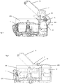
- the cooking apparatus shown in figure 1 comprises a housing 100 composed of a first compartment 101 and a second compartment 102.
- the first compartment 101 substantially corresponds to the cooking zone of the apparatus according to the invention.
- the first compartment 101 comprises a receiving means 1 or container provided for receiving the ingredients and a riddling means 2 disposed within the receiving means 1.
- the receiving means 1 has an upper opening 3.
- the receiving means 1 and the Riddling means 2 are designed to be driven relative rotational relative to each other. This movement is provided by a motor 25 placed under the container.
- the cooking appliance comprises at least one main heating means 10. As shown in FIG. figure 1 , the main heating means 10 generates a heating flow entering the receiving means 1 through the upper opening 3.
- the receiving means 1 is formed by a tank 20 having a bottom 21 and a side wall 22. According to the variant embodiment of the figure 1 , the bottom 21 is inclined downwards towards the side wall 22.
- the tank 20 has a central opening 23 provided for the passage of a drive shaft 24 rotated by a motor 25.
- the means of 2 is mounted on the drive shaft 24.
- the vessel 20 is preferably made of metal material, preferably coated metal material or stainless steel.
- the receiving means 1 comprises a handle 8.
- the receiving means 1 is removably mounted relative to the housing 100.
- the main heating means 10 comprises a transverse flow fan 12 mounted in the second compartment 102 of the housing 100.
- the fan 12 is for example mounted in a box 120.
- the axis of the fan 12 transverse flow is substantially parallel to the plane P of work.
- the fan 12 is designed to suck the air present in the first compartment 101 through an air intake 13 and to propel the air on a heating element 14 arranged in a nozzle 15.
- the nozzle 15 opens into the first compartment 101 at an output 40.
- the outlet 40 of the nozzle 15 is positioned above the receiving means 1.
- Another end 41 of the nozzle is adjacent to an outlet 121 of the well 120.
- the heating element 14 is positioned in the first compartment 101. This particular configuration makes it possible to reduce the size of the cooking appliance according to the invention.
- the heating element 14 is, for example, made of a resistive wire wound around a perforated mica support inserted into a metal body.
- the winding density of the wire is adjusted to limit the pressure drops and the formation of red dots during operation.
- the heating element 14 may comprise 2 openwork mica supports.
- the nozzle 15 is also positioned in the first compartment 101.
- the second compartment 102 comprises an intake zone 30 located upstream of the transverse flow fan 12. This intake zone 30 is intended to reduce the pressure losses upstream of the transverse flow fan 12.
- the intake zone 30 is connected with airflow with the first compartment 101 through the air intake 13.
- the housing 100 of the apparatus according to the invention also comprises a cover 7 and a base 9.
- the cover 7 is intended to cover at least the first compartment 101.
- the cover 7 may comprise a transparent porthole 75 positioned above the first compartment 101. compartment 101 to allow the user to follow the progress of cooking.
- the cover 7 is shaped to cover both the first compartment 101 and the second compartment 102.
- the cover 7 is mounted on the base 9 along a pivot axis 70.
- the axis 70 of pivoting is located in the second compartment 102 as far as possible from the first compartment 101.
- the pivot axis 70 is located near the outer edge of the housing 1.
- This configuration leaves a wide access to the first compartment 101 which facilitates the introduction and removal of the container 1 during the preparation of food.
- the nozzle 15 is mounted on the inner face of the lid 7.
- a seal 150 may be provided on the end of the nozzle 15 to prevent leakage of hot air between the nozzle 15 and the caisson 120 of the transverse flow fan 12.
- the lid 7 when the lid 7 is in the open position, the entire upper opening 3 of the container 1 is accessible. The introduction of food is thus facilitated.
- the fan 12 is fixed relative to the housing 100.
- the variant embodiment presented at figure 3 is identical in every respect to the variant embodiment of the figure 2 with the exception that the fan 12 is also pivotally mounted relative to the housing 100.
- the direction of pivoting of the fan 12 is identical to that of the cover 7.
- the pivot axis 71 of the fan is located between the first compartment 101 and the second compartment 102, for example at the upper edge of the container 1.
- a connecting rod 80 links the cover 7 and the fan 12.
- the connecting rod 80 is for example fixed on the nozzle 15 itself secured to the housing 120 of the fan.
- the pivot axis of the cover is coincident with the pivot axis of the fan. This axis is for example located between the first and second compartment of the housing.
- the cover 7 is shaped to cover only the first compartment 101.
- the cover 7 is mounted on the base 9 along a pivot axis 72.
- the pivot axis 72 is situated between the first compartment 101 and the second compartment 102 in an area situated above the upper opening 3 of the container 1.
- the receiving means 1 is not necessarily formed by a tank.
- the receiving means preferably has a bottom and a side wall.
- the receiving means may in particular be formed by a perforated basket.
Landscapes
- Engineering & Computer Science (AREA)
- Food Science & Technology (AREA)
- Chemical & Material Sciences (AREA)
- Combustion & Propulsion (AREA)
- Mechanical Engineering (AREA)
- General Engineering & Computer Science (AREA)
- Manufacturing & Machinery (AREA)
- Baking, Grill, Roasting (AREA)
- Cookers (AREA)
- Electric Stoves And Ranges (AREA)
Abstract
Description
- La présente invention concerne le domaine des appareils électriques de cuisson comportant un moyen de remuage agencé dans un moyen de réception d'aliments.
- Le document
FR2871042 - Un objet de la présente invention est de proposer un appareil de cuisson par flux chauffant et moyen de remuage plus compact et plus silencieux. Un autre objet de la présente invention consiste à augmenter l'efficacité du moyen de chauffe.
- Ces objets sont atteints avec un appareil de cuisson comprenant un boitier comprenant un premier compartiment formant un espace de cuisson, pourvu d'un moyen de réception prévu pour recevoir des ingrédients, un moyen de remuage disposé au sein du moyen de réception, le moyen de réception et le moyen de remuage étant conçus pour être animés d'un mouvement relatif de rotation l'un par rapport à l'autre, le boitier comprend un moyen de chauffe principal, comprenant, dans un deuxième compartiment, des moyens de ventilation pour générer un flux chauffant, caractérisé en ce que les moyens de ventilation comprennent un ventilateur à flux transversal, le moyen de chauffe principal comprend au moins un élément chauffant agencé dans le premier compartiment.
- L'utilisation d'un ventilateur à flux transversal permet tout d'abord de réduire le bruit de l'appareil en utilisation. Le positionnement des moyens de chauffage dans le premier compartiment permet de réduire l'encombrement, notamment la longueur de l'appareil. De plus, l'utilisation d'un ventilateur à flux transversal permet d'avoir un flux linéaire et non perturbé qui provoque un refroidissement homogène de l'élément chauffant. Ainsi, un élément chauffant du type filament enroulé autour de mica, ne présentera plus de points rouges sur le filament lors du chauffage. Cela permet également un bobinage régulier du fil sur le mica.
- Enfin, il est rappelé que la combinaison du positionnement du ventilateur à flux transversal et de l'au moins un élément chauffant est déterminante pour l'atteinte des performances de cuisson. Cela implique un travail sur le flux d'air, la géométrie et le dimensionnement du ventilateur à flux transversal mais également de l'au moins un élément chauffant.
- Selon un autre mode de réalisation, le deuxième compartiment comprend une zone d'admission en amont du ventilateur à flux transversal, agencée entre l'espace de cuisson et les moyens de ventilation, et en communication avec les moyens de ventilation.
- Selon un autre mode de réalisation, la hauteur de la zone d'admission est au moins égale au diamètre du ventilateur à flux transversal.
- Selon un autre mode de réalisation, la largeur de la zone d'admission est au moins égale à 1,5 fois le diamètre du ventilateur à flux transversal.
- Selon un autre mode de réalisation, la distance entre l'axe du ventilateur à flux transversal et un bord extérieur du boitier est au moins égale à 0,7 fois le diamètre du ventilateur à flux transversal.
- Selon un autre mode de réalisation, le moyen de chauffe principal comprend une tuyère pour guider le flux chauffant vers le moyen de réception, la tuyère débouchant dans le premier compartiment.
- Selon un autre mode de réalisation, l'au moins un élément chauffant est agencé dans la tuyère.
- Selon un autre mode de réalisation, la distance entre la périphérie du ventilateur à flux transversal et l'extrémité adjacente de la tuyère est au moins égale à 0.3 fois le diamètre du ventilateur à flux transversal.
- Selon un autre mode de réalisation, le boitier comprend un couvercle monté de façon pivotante et recouvrant les premier et deuxième compartiments, l'axe de pivotement étant positionné entre le deuxième compartiment et le bord extérieur du boitier.
- Selon un autre mode de réalisation, la tuyère est solidaire du couvercle et les moyens de ventilation sont fixes dans le deuxième compartiment.
- Selon un autre mode de réalisation, la tuyère est solidaire des moyens de ventilation et les moyens de ventilation pivotent dans le même sens que le couvercle, l'axe de pivotement des moyens de ventilation étant positionné entre le premier compartiment et le deuxième compartiment.
- Selon un autre mode de réalisation, le boitier comprend un couvercle monté de façon pivotante et recouvrant au moins le premier compartiment, l'axe de pivotement étant positionné entre le premier compartiment et le deuxième compartiment.
- Selon un autre mode de réalisation, le couvercle recouvre uniquement le premier compartiment et les moyens de ventilation sont fixes dans le deuxième compartiment.
- Selon un autre mode de réalisation, le couvercle recouvre le premier et le deuxième compartiments, les moyens de ventilation pivotent dans le même sens que le couvercle, l'axe de pivotement des moyens de ventilation étant confondu avec l'axe de pivotement du couvercle.
- D'autres avantages et particularités de la présente invention apparaîtront dans la description des modes de réalisation donnés à titre d'exemple non limitatif et illustrés par les dessins mis en annexe où :
- la
figure 1 est une vue en coupe longitudinale d'un premier exemple de réalisation d'un appareil de cuisson selon l'invention ; - la
figure 2 est une vue en coupe longitudinale du premier exemple de réalisation de l'appareil de cuisson avec le couvercle en position d'ouverture ; - la
figure 3 est une vue en coupe longitudinale d'un deuxième exemple de réalisation de l'appareil de cuisson avec le couvercle en position d'ouverture ; - la
figure 4 une vue en coupe longitudinale d'un troisième exemple de réalisation de l'appareil de cuisson avec le couvercle en position d'ouverture ; - L'appareil de cuisson représenté à la
figure 1 comprend un boitier 100 composé d'un premier compartiment 101 et d'un deuxième compartiment 102. Le premier compartiment 101 correspond sensiblement à la zone de cuisson de l'appareil selon l'invention. Le premier compartiment 101 comprend un moyen de réception 1 ou récipient prévu pour recevoir les ingrédients et un moyen de remuage 2 disposé au sein du moyen de réception 1. Le moyen de réception 1 présente une ouverture supérieure 3. Le moyen de réception 1 et le moyen de remuage 2 sont conçus pour être animés d'un mouvement relatif de rotation l'un par rapport à l'autre. Ce mouvement est assuré par un moteur 25 placé sous le récipient. - L'appareil de cuisson comporte au moins un moyen de chauffe principal 10. Tel que représenté sur la
figure 1 , le moyen de chauffe principal 10 génère un flux chauffant entrant dans le moyen de réception 1 par l'ouverture supérieure 3. - Plus particulièrement, le moyen de réception 1 est formé par une cuve 20 comportant un fond 21 et une paroi latérale 22. Selon la variante de réalisation de la
figure 1 , le fond 21 est incliné vers le bas en direction de la paroi latérale 22. La cuve 20 présente une ouverture centrale 23 prévue pour le passage d'un axe d'entraînement 24 entraîné en rotation par un moteur 25. Le moyen de remuage 2 est monté sur l'axe d'entraînement 24. La cuve 20 est avantageusement réalisée en matériau métallique, de préférence en matériau métallique revêtu ou en acier inoxydable. Le moyen de réception 1 comporte une poignée 8. Le moyen de réception 1 est monté amovible par rapport au boîtier 100. Selon l'invention, le moyen de chauffe principal 10 comprend un ventilateur 12 à flux transversal monté dans le deuxième compartiment 102 du boitier 100. Le ventilateur 12 est par exemple monté dans un caisson 120. L'axe du ventilateur 12 à flux transversal est sensiblement parallèle au plan P de travail. - Le ventilateur 12 est prévu pour aspirer l'air présent dans le premier compartiment 101 par une admission d'air 13 et pour propulser l'air sur un élément chauffant 14 agencé dans une tuyère 15. La tuyère 15 débouche dans le premier compartiment 101 au niveau d'une sortie 40. La sortie 40 de la tuyère 15 est positionnée au-dessus du moyen de réception 1. Une autre extrémité 41 de la tuyère est adjacente à un orifice de sortie 121 du caisson 120.
- Selon l'invention, l'élément chauffant 14 est positionné dans le premier compartiment 101. Cette configuration particulière permet de réduire la taille de l'appareil de cuisson selon l'invention.
- L'élément chauffant 14 est, par exemple, constitué d'un fil résistif enroulé autour d'un support en mica ajouré inséré dans un corps métallique. La densité d'enroulement du fil est ajustée pour limiter les pertes de charge et la formation de points rouges lors du fonctionnement. Selon une variante de réalisation, l'élément chauffant 14 peut comprendre 2 supports en mica ajouré.
- Selon une variante de réalisation, la tuyère 15 est également positionnée dans le premier compartiment 101.
- Le deuxième compartiment 102 comprend une zone d'admission 30 située en amont du ventilateur 12 à flux transversal. Cette zone d'admission 30 est destinée à réduire les pertes de charge en amont du ventilateur 12 à flux transversal. La zone d'admission 30 est en liaison aéraulique avec le premier compartiment 101 au travers de l'admission d'air 13.
- Les dimensions préférées de la zone d'admission 30 sont les suivantes :
- La hauteur a doit être au moins égal au diamètre D du ventilateur 12 à flux transversal
- La largeur b doit être au moins égal à 1,5 fois le diamètre D du ventilateur 12 à flux transversal
- la distance c entre l'axe du ventilateur 12 à flux transversal et un bord extérieur du boitier 100 doit être au moins égale à 0,7 fois le diamètre D du ventilateur 12 à flux transversal
- La distance d entre la périphérie du ventilateur 12 à flux transversal et l'orifice de sortie du caisson 120 doit être au moins égale à 0,3 fois le diamètre D du ventilateur 12 à flux transversal.
- Le boitier 100 de l'appareil selon l'invention comprend également un couvercle 7 et une embase 9. Le couvercle 7 est destiné à couvrir au moins le premier compartiment 101. Le couvercle 7 peut comprendre un hublot 75 transparent positionné au-dessus du premier compartiment 101 pour permettre à l'utilisateur de suivre l'avancement de la cuisson.
- Selon la variante de réalisation de la
figure 2 , le couvercle 7 est conformé pour couvrir à la fois le premier compartiment 101 et le deuxième compartiment 102. Le couvercle 7 est monté sur l'embase 9 selon un axe 70 de pivotement. Selon cette variante L'axe 70 de pivotement est situé dans le deuxième compartiment 102 le plus éloigné possible du premier compartiment 101. A titre d'exemple, l'axe de pivotement 70 est situé à proximité du bord extérieur du boitier 1. - Cette configuration laisse un large accès au premier compartiment 101 ce qui facilite l'introduction et le retrait du récipient 1 lors de la préparation des aliments.
- Afin d'augmenter encore l'accessibilité au premier compartiment 101, la tuyère 15 est montée sur la face interne du couvercle 7. Un joint d'étanchéité 150 peut être prévu sur l'extrémité de la tuyère 15 d'éviter les fuites d'air chaud entre la tuyère 15 et le caisson 120 du ventilateur 12 à flux transversal. Dans cette variante de réalisation, lorsque que le couvercle 7 est en position ouverte, l'intégralité de l'ouverture supérieure 3 du récipient 1 est accessible. L'introduction d'aliment est donc facilitée.
- Selon cette variante de réalisation, le ventilateur 12 est fixe par rapport au boitier 100.
- La variante de réalisation présentée à la
figure 3 , est identique en tout point à la variante de réalisation de lafigure 2 à l'exception du fait que le ventilateur 12 est également monté pivotant par rapport au boitier 100. Le sens du pivotement du ventilateur 12 est identique à celui du couvercle 7. L'axe de pivotement 71 du ventilateur est situé entre le premier compartiment 101 et le deuxième compartiment 102, par exemple au niveau du bord supérieur du récipient 1. Pour assurer la synchronisation du mouvement du couvercle 7 et du ventilateur, une bielle 80 lie le couvercle 7 et le ventilateur 12. Selon la variante de réalisation, la bielle 80 est par exemple fixée sur la tuyère 15 elle-même solidaire du caisson 120 du ventilateur. - Selon une autre variante de réalisation non représentée, l'axe de pivotement du couvercle est confondu avec l'axe de pivotement du ventilateur. Cet axe est par exemple situé entre le premier et le deuxième compartiment du boitier.
- Selon la variante de réalisation de la
figure 4 , le couvercle 7 est conformé pour couvrir uniquement le premier compartiment 101. Le couvercle 7 est monté sur l'embase 9 selon un axe 72 de pivotement. Selon cette variante l'axe 72 de pivotement est situé entre le premier compartiment 101 et le deuxième compartiment 102 dans une zone située au-dessus de l'ouverture supérieure 3 du récipient 1. - A titre de variante, le moyen de réception 1 n'est pas nécessairement formé par une cuve. Le moyen de réception présente de préférence un fond et une paroi latérale. Le moyen de réception peut notamment être formé par un panier ajouré.
- La présente invention n'est nullement limitée aux modes de réalisation décrits, mais englobe de nombreuses modifications dans le cadre des revendications.
Claims (14)
- Appareil de cuisson comprenant un boitier (100) comprenant un premier compartiment (101) formant un espace de cuisson, pourvu d'un moyen de réception (1) prévu pour recevoir des ingrédients, un moyen de remuage (2) disposé au sein du moyen de réception (1), le moyen de réception (1) et le moyen de remuage (2) étant conçus pour être animés d'un mouvement relatif de rotation l'un par rapport à l'autre, le boitier comprend un moyen de chauffe principal (10), comprenant, dans un deuxième compartiment (102), des moyens de ventilation (12) pour générer un flux chauffant, caractérisé en ce que les moyens de ventilation comprennent un ventilateur à flux transversal (12), le moyen de chauffe principal (10) comprend au moins un élément chauffant (14) agencé dans le premier compartiment (101).
- Appareil de cuisson selon la revendication précédente dans lequel le deuxième compartiment (102) comprend une zone d'admission (30) en amont du ventilateur à flux transversal (12), agencée entre l'espace de cuisson et les moyens de ventilation (12), et en communication avec les moyens de ventilation (12).
- Appareil de cuisson selon la revendication précédente dans lequel la hauteur (a) de la zone d'admission (30) est au moins égale au diamètre (D) du ventilateur (12) à flux transversal.
- Appareil de cuisson selon l'une des revendications 2 ou 3 dans lequel la largeur (b) de la zone d'admission (30) est au moins égale à 1,5 fois le diamètre (D) du ventilateur (12) à flux transversal.
- Appareil de cuisson selon l'une des revendications 2 à 4 dans lequel la distance (c) entre l'axe du ventilateur à flux transversal et un bord extérieur du boitier (100) est au moins égale à 0,7 fois le diamètre (D) du ventilateur à flux transversal (12).
- Appareil de cuisson selon l'une des revendications précédentes dans lequel le moyen de chauffe principal (10) comprend une tuyère (15) pour guider le flux chauffant vers le moyen de réception (1), la tuyère (15) débouchant dans le premier compartiment (101).
- Appareil de cuisson selon la revendication précédente dans lequel l'au moins un élément chauffant (14) est agencé dans la tuyère (15).
- Appareil de cuisson selon l'une des revendications 6 ou 7 dans lequel la distance (d) entre la périphérie du ventilateur (12) à flux transversal et l'extrémité (121) adjacente de la tuyère (15) est au moins égale à 0.3 fois le diamètre (D) du ventilateur (12) à flux transversal.
- Appareil de cuisson selon l'une des revendications précédentes dans lequel le boitier (100) comprend un couvercle (7) monté de façon pivotante et recouvrant les premier et deuxième compartiments (101, 102), l'axe de (70) pivotement étant positionné entre le deuxième compartiment (102) et le bord extérieur du boitier (100).
- Appareil de cuisson selon la revendication précédente dans lequel la tuyère (15) est solidaire du couvercle (7) et les moyens de ventilation (12) sont fixes dans le deuxième compartiment (102).
- Appareil de cuisson selon la revendication 9 dans lequel la tuyère (15) est solidaire des moyens de ventilation (12) et les moyens de ventilation (12) pivotent dans le même sens que le couvercle (7), l'axe de pivotement (71) des moyens de ventilation (12) étant positionné entre le premier compartiment (101) et le deuxième compartiment (102).
- Appareil de cuisson selon l'une des revendications 1 à 8 dans lequel le boitier (100) comprend un couvercle (7) monté de façon pivotante et recouvrant au moins le premier compartiment (101), l'axe de pivotement (71) étant positionné entre le premier compartiment (101) et le deuxième compartiment (102).
- Appareil de cuisson selon la revendication précédente dans lequel le couvercle (7) recouvre uniquement le premier compartiment (101) et les moyens de ventilation (12) sont fixes dans le deuxième compartiment (102).
- Appareil de cuisson selon l'une des revendications 1 à 8 dans lequel le couvercle (7) recouvre le premier et le deuxième compartiments (101, 102), les moyens de ventilation (12) pivotent dans le même sens que le couvercle (7), l'axe de pivotement des moyens de ventilation (12) étant confondu avec l'axe de pivotement du couvercle (7).
Applications Claiming Priority (1)
| Application Number | Priority Date | Filing Date | Title |
|---|---|---|---|
| FR1752538A FR3064169B1 (fr) | 2017-03-27 | 2017-03-27 | Appareil de cuisson par flux chauffant avec moyen de remuage |
Publications (2)
| Publication Number | Publication Date |
|---|---|
| EP3381338A1 true EP3381338A1 (fr) | 2018-10-03 |
| EP3381338B1 EP3381338B1 (fr) | 2022-11-23 |
Family
ID=59070827
Family Applications (1)
| Application Number | Title | Priority Date | Filing Date |
|---|---|---|---|
| EP18163786.9A Active EP3381338B1 (fr) | 2017-03-27 | 2018-03-23 | Appareil de cuisson par flux chauffant avec moyen de remuage |
Country Status (5)
| Country | Link |
|---|---|
| US (1) | US10813491B2 (fr) |
| EP (1) | EP3381338B1 (fr) |
| CN (2) | CN209121851U (fr) |
| CA (1) | CA2993737C (fr) |
| FR (1) | FR3064169B1 (fr) |
Families Citing this family (14)
| Publication number | Priority date | Publication date | Assignee | Title |
|---|---|---|---|---|
| EP3865028A1 (fr) | 2017-08-09 | 2021-08-18 | SharkNinja Operating LLC | Dispositif de cuisson et ses composants |
| USD914436S1 (en) | 2018-06-19 | 2021-03-30 | Sharkninja Operating Llc | Air diffuser with food preparation pot |
| USD883014S1 (en) | 2018-08-09 | 2020-05-05 | Sharkninja Operating Llc | Food preparation device |
| USD883015S1 (en) | 2018-08-09 | 2020-05-05 | Sharkninja Operating Llc | Food preparation device and parts thereof |
| USD934027S1 (en) | 2018-08-09 | 2021-10-26 | Sharkninja Operating Llc | Reversible cooking rack |
| USD903413S1 (en) | 2018-08-09 | 2020-12-01 | Sharkninja Operating Llc | Cooking basket |
| CN212788226U (zh) | 2019-02-25 | 2021-03-26 | 沙克忍者运营有限责任公司 | 烹饪系统 |
| US11051654B2 (en) | 2019-02-25 | 2021-07-06 | Sharkninja Operating Llc | Cooking device and components thereof |
| USD918654S1 (en) | 2019-06-06 | 2021-05-11 | Sharkninja Operating Llc | Grill plate |
| USD982375S1 (en) | 2019-06-06 | 2023-04-04 | Sharkninja Operating Llc | Food preparation device |
| US11647861B2 (en) | 2020-03-30 | 2023-05-16 | Sharkninja Operating Llc | Cooking device and components thereof |
| CN114224199B (zh) * | 2021-12-20 | 2023-06-13 | 永康市新本电器科技有限公司 | 一种风道结构改良的空气炸锅 |
| US11882961B1 (en) | 2023-01-18 | 2024-01-30 | Sharkninja Operating Llc | Cover plate for cooking devices |
| USD1083485S1 (en) | 2023-08-29 | 2025-07-15 | Sharkninja Operating Llc | Stacked air fryer |
Citations (4)
| Publication number | Priority date | Publication date | Assignee | Title |
|---|---|---|---|---|
| FR2871042A1 (fr) * | 2004-06-08 | 2005-12-09 | Seb Sa | Friteuse a enduction automatique de matiere grasse |
| US20150292750A1 (en) * | 2012-10-31 | 2015-10-15 | Seb S.A. | Electric Cooking Apparatus Having an Air Flow |
| FR3029096A1 (fr) * | 2014-12-02 | 2016-06-03 | Seb Sa | Appareil et procede de cuisson et/ou rechauffage |
| CN205697284U (zh) * | 2016-04-11 | 2016-11-23 | 浙江绍兴苏泊尔生活电器有限公司 | 烹饪器具 |
Family Cites Families (9)
| Publication number | Priority date | Publication date | Assignee | Title |
|---|---|---|---|---|
| KR950007763A (ko) * | 1993-09-17 | 1995-04-15 | 이헌조 | 전자유도가열 밥솥의 통풍장치 |
| ATE473666T1 (de) * | 2004-06-08 | 2010-07-15 | Seb Sa | Luftstromkochvorrichtung |
| JP4585910B2 (ja) * | 2005-05-10 | 2010-11-24 | 日立アプライアンス株式会社 | 加熱調理器 |
| JP2007003136A (ja) * | 2005-06-27 | 2007-01-11 | Hitachi Appliances Inc | 加熱調理器 |
| CN202020279U (zh) * | 2011-04-27 | 2011-11-02 | 张毅蔚 | 一种多功能炒菜机 |
| CN102793477B (zh) * | 2012-08-27 | 2015-07-08 | 周林斌 | 一种导气流罩加热食物的方法 |
| FR2995775B1 (fr) * | 2012-09-26 | 2014-09-26 | Seb Sa | Appareil electrique domestique de cuisson a flux d'air |
| JP6017941B2 (ja) * | 2012-11-30 | 2016-11-02 | シャープ株式会社 | 加熱調理器 |
| JP2015010743A (ja) * | 2013-06-27 | 2015-01-19 | シャープ株式会社 | 加熱調理装置 |
-
2017
- 2017-03-27 FR FR1752538A patent/FR3064169B1/fr active Active
-
2018
- 2018-01-31 CA CA2993737A patent/CA2993737C/fr active Active
- 2018-03-23 EP EP18163786.9A patent/EP3381338B1/fr active Active
- 2018-03-26 US US15/935,824 patent/US10813491B2/en active Active
- 2018-03-27 CN CN201820419635.9U patent/CN209121851U/zh active Active
- 2018-03-27 CN CN201810259560.7A patent/CN108652417B/zh active Active
Patent Citations (4)
| Publication number | Priority date | Publication date | Assignee | Title |
|---|---|---|---|---|
| FR2871042A1 (fr) * | 2004-06-08 | 2005-12-09 | Seb Sa | Friteuse a enduction automatique de matiere grasse |
| US20150292750A1 (en) * | 2012-10-31 | 2015-10-15 | Seb S.A. | Electric Cooking Apparatus Having an Air Flow |
| FR3029096A1 (fr) * | 2014-12-02 | 2016-06-03 | Seb Sa | Appareil et procede de cuisson et/ou rechauffage |
| CN205697284U (zh) * | 2016-04-11 | 2016-11-23 | 浙江绍兴苏泊尔生活电器有限公司 | 烹饪器具 |
Also Published As
| Publication number | Publication date |
|---|---|
| FR3064169B1 (fr) | 2019-03-22 |
| FR3064169A1 (fr) | 2018-09-28 |
| CN108652417B (zh) | 2022-03-22 |
| CN209121851U (zh) | 2019-07-19 |
| CA2993737C (fr) | 2026-02-10 |
| US20180271321A1 (en) | 2018-09-27 |
| EP3381338B1 (fr) | 2022-11-23 |
| CA2993737A1 (fr) | 2018-09-27 |
| US10813491B2 (en) | 2020-10-27 |
| CN108652417A (zh) | 2018-10-16 |
Similar Documents
| Publication | Publication Date | Title |
|---|---|---|
| EP3381338B1 (fr) | Appareil de cuisson par flux chauffant avec moyen de remuage | |
| CA2899678C (fr) | Appareil de cuisson par flux d'air | |
| EP3207840B1 (fr) | Appareil de cuisson a flux d'air | |
| EP1768535B1 (fr) | Appareil de cuisson a flux d'air | |
| EP0343141B1 (fr) | Appareil de cuisson d'aliments | |
| CA3033985C (fr) | Appareil electrique de cuisson pour la preparation d'aliments frits | |
| EP3257410B1 (fr) | Appareil de cuisson a flux d'air | |
| EP1781154B1 (fr) | Friteuse a enduction automatique de matiere grasse | |
| EP2592983B1 (fr) | Appareil de cuisson en deux zones | |
| EP3880044B1 (fr) | Appareil de cuisson du type friteuse a air chaud muni d'une entree d'air frais et d'une sortie d'air chaud optimisees | |
| EP3435825A1 (fr) | Cuiseur a air chaud | |
| FR3060286A1 (fr) | Accessoire cuiseur vapeur modulaire pour chauffer et/ou cuire a la vapeur des aliments contenus dans un recipient | |
| EP4151132B1 (fr) | Appareil de cuisson electrique | |
| FR2984971B1 (fr) | Roue de ventilation centrifuge, ventilateur correspondant et appareil de cuisson incluant un tel ventilateur | |
| EP3593686B1 (fr) | Système de ventilation d'un mixeur | |
| WO2013072626A1 (fr) | Seche-cheveux avec ailettes concentriques | |
| FR2905584A1 (fr) | Mixeur menager de type plongeant comportant un outil de travail presentant la forme d'une vis d'archimede. |
Legal Events
| Date | Code | Title | Description |
|---|---|---|---|
| PUAI | Public reference made under article 153(3) epc to a published international application that has entered the european phase |
Free format text: ORIGINAL CODE: 0009012 |
|
| STAA | Information on the status of an ep patent application or granted ep patent |
Free format text: STATUS: THE APPLICATION HAS BEEN PUBLISHED |
|
| AK | Designated contracting states |
Kind code of ref document: A1 Designated state(s): AL AT BE BG CH CY CZ DE DK EE ES FI FR GB GR HR HU IE IS IT LI LT LU LV MC MK MT NL NO PL PT RO RS SE SI SK SM TR |
|
| AX | Request for extension of the european patent |
Extension state: BA ME |
|
| STAA | Information on the status of an ep patent application or granted ep patent |
Free format text: STATUS: REQUEST FOR EXAMINATION WAS MADE |
|
| 17P | Request for examination filed |
Effective date: 20190311 |
|
| RBV | Designated contracting states (corrected) |
Designated state(s): AL AT BE BG CH CY CZ DE DK EE ES FI FR GB GR HR HU IE IS IT LI LT LU LV MC MK MT NL NO PL PT RO RS SE SI SK SM TR |
|
| STAA | Information on the status of an ep patent application or granted ep patent |
Free format text: STATUS: EXAMINATION IS IN PROGRESS |
|
| 17Q | First examination report despatched |
Effective date: 20201106 |
|
| GRAP | Despatch of communication of intention to grant a patent |
Free format text: ORIGINAL CODE: EPIDOSNIGR1 |
|
| STAA | Information on the status of an ep patent application or granted ep patent |
Free format text: STATUS: GRANT OF PATENT IS INTENDED |
|
| RIC1 | Information provided on ipc code assigned before grant |
Ipc: A47J 37/06 20060101ALI20220520BHEP Ipc: A47J 37/04 20060101AFI20220520BHEP |
|
| INTG | Intention to grant announced |
Effective date: 20220623 |
|
| GRAS | Grant fee paid |
Free format text: ORIGINAL CODE: EPIDOSNIGR3 |
|
| GRAA | (expected) grant |
Free format text: ORIGINAL CODE: 0009210 |
|
| STAA | Information on the status of an ep patent application or granted ep patent |
Free format text: STATUS: THE PATENT HAS BEEN GRANTED |
|
| AK | Designated contracting states |
Kind code of ref document: B1 Designated state(s): AL AT BE BG CH CY CZ DE DK EE ES FI FR GB GR HR HU IE IS IT LI LT LU LV MC MK MT NL NO PL PT RO RS SE SI SK SM TR |
|
| REG | Reference to a national code |
Ref country code: GB Ref legal event code: FG4D Free format text: NOT ENGLISH |
|
| REG | Reference to a national code |
Ref country code: CH Ref legal event code: EP |
|
| REG | Reference to a national code |
Ref country code: DE Ref legal event code: R096 Ref document number: 602018043281 Country of ref document: DE |
|
| REG | Reference to a national code |
Ref country code: AT Ref legal event code: REF Ref document number: 1532611 Country of ref document: AT Kind code of ref document: T Effective date: 20221215 |
|
| REG | Reference to a national code |
Ref country code: IE Ref legal event code: FG4D Free format text: LANGUAGE OF EP DOCUMENT: FRENCH |
|
| REG | Reference to a national code |
Ref country code: LT Ref legal event code: MG9D |
|
| REG | Reference to a national code |
Ref country code: NL Ref legal event code: MP Effective date: 20221123 |
|
| REG | Reference to a national code |
Ref country code: AT Ref legal event code: MK05 Ref document number: 1532611 Country of ref document: AT Kind code of ref document: T Effective date: 20221123 |
|
| PG25 | Lapsed in a contracting state [announced via postgrant information from national office to epo] |
Ref country code: SE Free format text: LAPSE BECAUSE OF FAILURE TO SUBMIT A TRANSLATION OF THE DESCRIPTION OR TO PAY THE FEE WITHIN THE PRESCRIBED TIME-LIMIT Effective date: 20221123 Ref country code: PT Free format text: LAPSE BECAUSE OF FAILURE TO SUBMIT A TRANSLATION OF THE DESCRIPTION OR TO PAY THE FEE WITHIN THE PRESCRIBED TIME-LIMIT Effective date: 20230323 Ref country code: NO Free format text: LAPSE BECAUSE OF FAILURE TO SUBMIT A TRANSLATION OF THE DESCRIPTION OR TO PAY THE FEE WITHIN THE PRESCRIBED TIME-LIMIT Effective date: 20230223 Ref country code: LT Free format text: LAPSE BECAUSE OF FAILURE TO SUBMIT A TRANSLATION OF THE DESCRIPTION OR TO PAY THE FEE WITHIN THE PRESCRIBED TIME-LIMIT Effective date: 20221123 Ref country code: FI Free format text: LAPSE BECAUSE OF FAILURE TO SUBMIT A TRANSLATION OF THE DESCRIPTION OR TO PAY THE FEE WITHIN THE PRESCRIBED TIME-LIMIT Effective date: 20221123 Ref country code: ES Free format text: LAPSE BECAUSE OF FAILURE TO SUBMIT A TRANSLATION OF THE DESCRIPTION OR TO PAY THE FEE WITHIN THE PRESCRIBED TIME-LIMIT Effective date: 20221123 Ref country code: AT Free format text: LAPSE BECAUSE OF FAILURE TO SUBMIT A TRANSLATION OF THE DESCRIPTION OR TO PAY THE FEE WITHIN THE PRESCRIBED TIME-LIMIT Effective date: 20221123 |
|
| PG25 | Lapsed in a contracting state [announced via postgrant information from national office to epo] |
Ref country code: RS Free format text: LAPSE BECAUSE OF FAILURE TO SUBMIT A TRANSLATION OF THE DESCRIPTION OR TO PAY THE FEE WITHIN THE PRESCRIBED TIME-LIMIT Effective date: 20221123 Ref country code: PL Free format text: LAPSE BECAUSE OF FAILURE TO SUBMIT A TRANSLATION OF THE DESCRIPTION OR TO PAY THE FEE WITHIN THE PRESCRIBED TIME-LIMIT Effective date: 20221123 Ref country code: LV Free format text: LAPSE BECAUSE OF FAILURE TO SUBMIT A TRANSLATION OF THE DESCRIPTION OR TO PAY THE FEE WITHIN THE PRESCRIBED TIME-LIMIT Effective date: 20221123 Ref country code: IS Free format text: LAPSE BECAUSE OF FAILURE TO SUBMIT A TRANSLATION OF THE DESCRIPTION OR TO PAY THE FEE WITHIN THE PRESCRIBED TIME-LIMIT Effective date: 20230323 Ref country code: HR Free format text: LAPSE BECAUSE OF FAILURE TO SUBMIT A TRANSLATION OF THE DESCRIPTION OR TO PAY THE FEE WITHIN THE PRESCRIBED TIME-LIMIT Effective date: 20221123 Ref country code: GR Free format text: LAPSE BECAUSE OF FAILURE TO SUBMIT A TRANSLATION OF THE DESCRIPTION OR TO PAY THE FEE WITHIN THE PRESCRIBED TIME-LIMIT Effective date: 20230224 |
|
| PG25 | Lapsed in a contracting state [announced via postgrant information from national office to epo] |
Ref country code: NL Free format text: LAPSE BECAUSE OF FAILURE TO SUBMIT A TRANSLATION OF THE DESCRIPTION OR TO PAY THE FEE WITHIN THE PRESCRIBED TIME-LIMIT Effective date: 20221123 |
|
| PG25 | Lapsed in a contracting state [announced via postgrant information from national office to epo] |
Ref country code: SM Free format text: LAPSE BECAUSE OF FAILURE TO SUBMIT A TRANSLATION OF THE DESCRIPTION OR TO PAY THE FEE WITHIN THE PRESCRIBED TIME-LIMIT Effective date: 20221123 Ref country code: RO Free format text: LAPSE BECAUSE OF FAILURE TO SUBMIT A TRANSLATION OF THE DESCRIPTION OR TO PAY THE FEE WITHIN THE PRESCRIBED TIME-LIMIT Effective date: 20221123 Ref country code: EE Free format text: LAPSE BECAUSE OF FAILURE TO SUBMIT A TRANSLATION OF THE DESCRIPTION OR TO PAY THE FEE WITHIN THE PRESCRIBED TIME-LIMIT Effective date: 20221123 Ref country code: DK Free format text: LAPSE BECAUSE OF FAILURE TO SUBMIT A TRANSLATION OF THE DESCRIPTION OR TO PAY THE FEE WITHIN THE PRESCRIBED TIME-LIMIT Effective date: 20221123 Ref country code: CZ Free format text: LAPSE BECAUSE OF FAILURE TO SUBMIT A TRANSLATION OF THE DESCRIPTION OR TO PAY THE FEE WITHIN THE PRESCRIBED TIME-LIMIT Effective date: 20221123 |
|
| REG | Reference to a national code |
Ref country code: DE Ref legal event code: R097 Ref document number: 602018043281 Country of ref document: DE |
|
| PG25 | Lapsed in a contracting state [announced via postgrant information from national office to epo] |
Ref country code: SK Free format text: LAPSE BECAUSE OF FAILURE TO SUBMIT A TRANSLATION OF THE DESCRIPTION OR TO PAY THE FEE WITHIN THE PRESCRIBED TIME-LIMIT Effective date: 20221123 Ref country code: AL Free format text: LAPSE BECAUSE OF FAILURE TO SUBMIT A TRANSLATION OF THE DESCRIPTION OR TO PAY THE FEE WITHIN THE PRESCRIBED TIME-LIMIT Effective date: 20221123 |
|
| PLBE | No opposition filed within time limit |
Free format text: ORIGINAL CODE: 0009261 |
|
| STAA | Information on the status of an ep patent application or granted ep patent |
Free format text: STATUS: NO OPPOSITION FILED WITHIN TIME LIMIT |
|
| PG25 | Lapsed in a contracting state [announced via postgrant information from national office to epo] |
Ref country code: MC Free format text: LAPSE BECAUSE OF FAILURE TO SUBMIT A TRANSLATION OF THE DESCRIPTION OR TO PAY THE FEE WITHIN THE PRESCRIBED TIME-LIMIT Effective date: 20221123 |
|
| REG | Reference to a national code |
Ref country code: CH Ref legal event code: PL |
|
| 26N | No opposition filed |
Effective date: 20230824 |
|
| PG25 | Lapsed in a contracting state [announced via postgrant information from national office to epo] |
Ref country code: SI Free format text: LAPSE BECAUSE OF FAILURE TO SUBMIT A TRANSLATION OF THE DESCRIPTION OR TO PAY THE FEE WITHIN THE PRESCRIBED TIME-LIMIT Effective date: 20221123 |
|
| PG25 | Lapsed in a contracting state [announced via postgrant information from national office to epo] |
Ref country code: LU Free format text: LAPSE BECAUSE OF NON-PAYMENT OF DUE FEES Effective date: 20230323 |
|
| REG | Reference to a national code |
Ref country code: IE Ref legal event code: MM4A |
|
| PG25 | Lapsed in a contracting state [announced via postgrant information from national office to epo] |
Ref country code: LI Free format text: LAPSE BECAUSE OF NON-PAYMENT OF DUE FEES Effective date: 20230331 Ref country code: IE Free format text: LAPSE BECAUSE OF NON-PAYMENT OF DUE FEES Effective date: 20230323 Ref country code: CH Free format text: LAPSE BECAUSE OF NON-PAYMENT OF DUE FEES Effective date: 20230331 |
|
| PG25 | Lapsed in a contracting state [announced via postgrant information from national office to epo] |
Ref country code: IT Free format text: LAPSE BECAUSE OF FAILURE TO SUBMIT A TRANSLATION OF THE DESCRIPTION OR TO PAY THE FEE WITHIN THE PRESCRIBED TIME-LIMIT Effective date: 20221123 |
|
| PG25 | Lapsed in a contracting state [announced via postgrant information from national office to epo] |
Ref country code: BG Free format text: LAPSE BECAUSE OF FAILURE TO SUBMIT A TRANSLATION OF THE DESCRIPTION OR TO PAY THE FEE WITHIN THE PRESCRIBED TIME-LIMIT Effective date: 20221123 |
|
| PG25 | Lapsed in a contracting state [announced via postgrant information from national office to epo] |
Ref country code: BG Free format text: LAPSE BECAUSE OF FAILURE TO SUBMIT A TRANSLATION OF THE DESCRIPTION OR TO PAY THE FEE WITHIN THE PRESCRIBED TIME-LIMIT Effective date: 20221123 |
|
| PGFP | Annual fee paid to national office [announced via postgrant information from national office to epo] |
Ref country code: DE Payment date: 20250313 Year of fee payment: 8 |
|
| PGFP | Annual fee paid to national office [announced via postgrant information from national office to epo] |
Ref country code: BE Payment date: 20250324 Year of fee payment: 8 |
|
| PGFP | Annual fee paid to national office [announced via postgrant information from national office to epo] |
Ref country code: GB Payment date: 20250324 Year of fee payment: 8 |
|
| PG25 | Lapsed in a contracting state [announced via postgrant information from national office to epo] |
Ref country code: CY Free format text: LAPSE BECAUSE OF FAILURE TO SUBMIT A TRANSLATION OF THE DESCRIPTION OR TO PAY THE FEE WITHIN THE PRESCRIBED TIME-LIMIT; INVALID AB INITIO Effective date: 20180323 |
|
| PG25 | Lapsed in a contracting state [announced via postgrant information from national office to epo] |
Ref country code: HU Free format text: LAPSE BECAUSE OF FAILURE TO SUBMIT A TRANSLATION OF THE DESCRIPTION OR TO PAY THE FEE WITHIN THE PRESCRIBED TIME-LIMIT; INVALID AB INITIO Effective date: 20180323 |
|
| PG25 | Lapsed in a contracting state [announced via postgrant information from national office to epo] |
Ref country code: TR Free format text: LAPSE BECAUSE OF FAILURE TO SUBMIT A TRANSLATION OF THE DESCRIPTION OR TO PAY THE FEE WITHIN THE PRESCRIBED TIME-LIMIT Effective date: 20221123 |
|
| PGFP | Annual fee paid to national office [announced via postgrant information from national office to epo] |
Ref country code: FR Payment date: 20260330 Year of fee payment: 9 |