EP3380930B1 - Entwicklungssystem für arbeitsablauf mit benutzerfreundlichen funktionen - Google Patents
Entwicklungssystem für arbeitsablauf mit benutzerfreundlichen funktionen Download PDFInfo
- Publication number
- EP3380930B1 EP3380930B1 EP16805942.6A EP16805942A EP3380930B1 EP 3380930 B1 EP3380930 B1 EP 3380930B1 EP 16805942 A EP16805942 A EP 16805942A EP 3380930 B1 EP3380930 B1 EP 3380930B1
- Authority
- EP
- European Patent Office
- Prior art keywords
- workflow
- name
- developer
- under development
- steps
- Prior art date
- Legal status (The legal status is an assumption and is not a legal conclusion. Google has not performed a legal analysis and makes no representation as to the accuracy of the status listed.)
- Active
Links
Images








Classifications
-
- G—PHYSICS
- G06—COMPUTING OR CALCULATING; COUNTING
- G06F—ELECTRIC DIGITAL DATA PROCESSING
- G06F8/00—Arrangements for software engineering
- G06F8/20—Software design
- G06F8/22—Procedural
-
- G—PHYSICS
- G06—COMPUTING OR CALCULATING; COUNTING
- G06F—ELECTRIC DIGITAL DATA PROCESSING
- G06F3/00—Input arrangements for transferring data to be processed into a form capable of being handled by the computer; Output arrangements for transferring data from processing unit to output unit, e.g. interface arrangements
- G06F3/01—Input arrangements or combined input and output arrangements for interaction between user and computer
- G06F3/011—Arrangements for interaction with the human body, e.g. for user immersion in virtual reality
-
- G—PHYSICS
- G06—COMPUTING OR CALCULATING; COUNTING
- G06F—ELECTRIC DIGITAL DATA PROCESSING
- G06F8/00—Arrangements for software engineering
- G06F8/10—Requirements analysis; Specification techniques
-
- G—PHYSICS
- G06—COMPUTING OR CALCULATING; COUNTING
- G06F—ELECTRIC DIGITAL DATA PROCESSING
- G06F8/00—Arrangements for software engineering
- G06F8/30—Creation or generation of source code
- G06F8/34—Graphical or visual programming
-
- G—PHYSICS
- G06—COMPUTING OR CALCULATING; COUNTING
- G06F—ELECTRIC DIGITAL DATA PROCESSING
- G06F8/00—Arrangements for software engineering
- G06F8/30—Creation or generation of source code
- G06F8/36—Software reuse
-
- G—PHYSICS
- G06—COMPUTING OR CALCULATING; COUNTING
- G06Q—INFORMATION AND COMMUNICATION TECHNOLOGY [ICT] SPECIALLY ADAPTED FOR ADMINISTRATIVE, COMMERCIAL, FINANCIAL, MANAGERIAL OR SUPERVISORY PURPOSES; SYSTEMS OR METHODS SPECIALLY ADAPTED FOR ADMINISTRATIVE, COMMERCIAL, FINANCIAL, MANAGERIAL OR SUPERVISORY PURPOSES, NOT OTHERWISE PROVIDED FOR
- G06Q10/00—Administration; Management
- G06Q10/06—Resources, workflows, human or project management; Enterprise or organisation planning; Enterprise or organisation modelling
-
- G—PHYSICS
- G06—COMPUTING OR CALCULATING; COUNTING
- G06Q—INFORMATION AND COMMUNICATION TECHNOLOGY [ICT] SPECIALLY ADAPTED FOR ADMINISTRATIVE, COMMERCIAL, FINANCIAL, MANAGERIAL OR SUPERVISORY PURPOSES; SYSTEMS OR METHODS SPECIALLY ADAPTED FOR ADMINISTRATIVE, COMMERCIAL, FINANCIAL, MANAGERIAL OR SUPERVISORY PURPOSES, NOT OTHERWISE PROVIDED FOR
- G06Q10/00—Administration; Management
- G06Q10/06—Resources, workflows, human or project management; Enterprise or organisation planning; Enterprise or organisation modelling
- G06Q10/063—Operations research, analysis or management
- G06Q10/0633—Workflow analysis
Definitions
- a business or enterprise application is a computer program used by business users to perform various business functions.
- Business applications are frequently developed when available off-the-shelf software does not completely address the desired functionality.
- Many business applications are interactive, having a graphical user interface (GUI) via which users can input data, submit data queries, perform operations, and view results.
- GUI graphical user interface
- Consumer applications are less business focused, instead being focused on the needs of the consumer.
- IT information technology
- Developing business and consumer applications is an activity that is typically performed on desktop computer systems having relatively large displays and a standard keyboard and mouse for accepting user input. Consequently, many tools for developing business and consumer applications do not include GUIs that are designed to efficiently use whatever screen space is available for displaying the GUI. Likewise, many tools for developing business and consumer applications do not include GUIs that take advantage of touch-based user input schemes or other techniques for reducing the amount of user interaction and user input required to develop such applications.
- US 2012/079409 A1 provides approaches for workflow creation and management at a scanning device.
- workflow service prompts the user if the user would like to store the current set of operations as a workflow, which can be later presented to an selected by the user. If the user indicates in the affirmative that the user would like the workflow to be stored and later presented to the user as a workflow option, then the scanning device sends the affirmative indication to workflow service.
- workflow service stores data that indicates that the set of operations is to be considered a workflow.
- workflow service might send to scanning device, a name prompt message requesting the user to name the workflow. If the user does not provide a name for the workflow, then workflow service automatically generates a name for the workflow.
- Methods, systems, apparatuses, and computer program products are also described herein that automatically generate a meaningful name and/or graphical representation (e.g., an icon) for a workflow.
- the name and/or graphical representation are generated, for example, based on steps included in the workflow and/or on one or more services that are referenced by the workflow.
- references in the specification to "one embodiment,” “an embodiment,” “an example embodiment,” or the like, indicate that the embodiment described may include a particular feature, structure, or characteristic, but every embodiment may not necessarily include the particular feature, structure, or characteristic. Moreover, such phrases are not necessarily referring to the same embodiment. Further, when a particular feature, structure, or characteristic is described in connection with an embodiment, it is submitted that it is within the knowledge of persons skilled in the relevant art(s) to implement such feature, structure, or characteristic in connection with other embodiments whether or not explicitly described.
- adjectives such as “substantially” and “about” modifying a condition or relationship characteristic of a feature or features of an embodiment of the disclosure are understood to mean that the condition or characteristic is defined to within tolerances that are acceptable for operation of the embodiment for an application for which it is intended.
- Section II below will describe example embodiments for development of workflows.
- Sub-sections A and B of Section II describe example workflow development embodiments and runtime embodiments, respectively.
- Sub-sections C, D and E will describe ease of use features that can be implemented in a workflow development system.
- sub-section C of Section II describes examples for workflow development that incorporate a search engine
- sub-section D of Section II describes embodiments for automatic generation of names and graphical representations of workflows
- sub-section E of Section II describes examples for easily specifying input parameter values for a workflow step of a workflow under development.
- Section III will describe an example mobile device that may be used to implement features of the embodiments described herein.
- Section IV will describe an example processor-based computer system that may be used to implement features of the embodiments described herein.
- Section V below will describe some additional example embodiments. Section VI will provide some concluding remarks.
- Business applications and consumer applications are typically created when available off-the-shelf software does not completely address the desired functionality. Many business and consumer applications are interactive, having a GUI via which users can input data, submit data queries, perform operations, and view results.
- an application to retrieve data from a source of interest to enterprises or consumers (e.g., data from an SQL (structured query language) database, customer relationship information from Salesforce.com of San Francisco, California, social network information from Facebook ® operated by Facebook, Inc. of Palo Alto, California, or Twitter ® operated by Twitter, Inc. of San Francisco, California) is a difficult process.
- a source of interest to enterprises or consumers e.g., data from an SQL (structured query language) database, customer relationship information from Salesforce.com of San Francisco, California, social network information from Facebook ® operated by Facebook, Inc. of Palo Alto, California, or Twitter ® operated by Twitter, Inc. of San Francisco, California
- Embodiments described herein enable easier development of applications, including business applications and consumer applications. Users are enabled to develop applications in the form of workflows without having to be expert programmers.
- Example embodiments are described in the following subsections for development of applications in the form of workflows.
- a person that develops an application using the techniques described herein is referred to as a "developer,” to be distinguished from a person that uses the application at runtime (a "user” or “end user”). It is noted, however, that a "developer,” as referred to herein, does not need to have any expertise in computer programming.
- Various embodiments described herein enable application development without special programming skills.
- FIG. 1 is a block diagram of a workflow development system 100, according to an example embodiment.
- system 100 includes a computing device 102, storage 104, a first network-based application 124A, a second network-based application 124B, and a server 134.
- Server 134 includes a workflow designer 106 and a workflow library 118 (e.g., in storage).
- Computing device 102 includes a display screen 108 and a browser 136.
- Storage 104 stores a local application 122.
- System 100 is described as follows.
- Computing device 102 may be any type computing device, including a mobile computing device (e.g., a smart phone, a Microsoft ® Surface ® device, a laptop computer, a notebook computer, a tablet computer such as an Apple iPad TM , a netbook, etc.), a wearable computing device (e.g., a head-mounted device including smart glasses such as Google ® Glass TM , etc.), or a stationary computing device such as a desktop computer or PC (personal computer).
- Server 134 may include one or more server devices and/or other computing devices.
- Local application 122 in storage 104 is an example of an application accessible by computing device 102 without communicating over a network.
- Local application 122 may be configured to perform data processing and/or data hosting operations when executed by a processor of computing device 102, and may provide data 132 to workflows developed using workflow designer 106 when such workflows are executed at runtime.
- Local application 122 may be any type of local application or service, such as a database application (e.g., QuickBooks ® , a Microsoft ® Excel ® spreadsheet), an e-mail application (e.g., Microsoft ® Outlook ® ), a productivity application (e.g., Microsoft ® Word ® , Microsoft ® PowerPoint ® , etc.), or another type of application.
- FIG. 1 shows a single local application, any number of local applications may be present at computing device 102, including numbers in the tens, hundreds, or greater numbers.
- First and second network-based applications 124A and 124B are examples of network-based applications, which in some instances may be referred to as "cloud" applications or services.
- Network-based applications 124A and 124B are accessible by computing device 102 over network 126, may be configured to perform data processing and/or data hosting operations, and may provide data 130A and 130B, respectively, to workflows created using workflow designer 106 when such workflows are executed at runtime.
- Network-based applications 124A and 124B may each be any type of network-accessible applications or services, such as database applications, social networking applications, messaging applications, financial services applications, news applications, search applications, productivity applications, cloud storage applications, file hosting applications, etc.
- Examples of such applications include a network-accessible SQL (structured query language) database, Salesforce.com TM , Facebook ® , Twitter ® , Instagram ® , Yammer ® , LinkedIn ® , Yahoo! ® Finance, The New York Times ® (at www.nytimes.com), Google search, Microsoft ® Bing, Google Docs TM , Microsoft ® Office 365, Dropbox TM , etc.
- FIG. 1 shows two network-based applications, any number of network-based applications may be accessible over network 126, including numbers in the tens, hundreds, thousands, or greater numbers.
- data 130A, data 130B, and data 132 may each include any type of data, including messages, notifications, calculated data, retrieved data, structured data, unstructured data, and/or any other type of information requested or usable by a workflow.
- Computing device 102 and server 134 may each include at least one wired or wireless network interface that enables communications with each other and with network-based applications 124A and 124B over network 126.
- a network interface include an IEEE 802.11 wireless LAN (WLAN) wireless interface, a Worldwide Interoperability for Microwave Access (Wi-MAX) interface, an Ethernet interface, a Universal Serial Bus (USB) interface, a cellular network interface, a Bluetooth TM interface, a near field communication (NFC) interface, etc. Further examples of network interfaces are described elsewhere herein.
- Examples of network 126 include a local area network (LAN), a wide area network (WAN) such as the Internet, a personal area network (PAN), and/or a combination of communication networks.
- Workflow designer 106 is configured to be operated/interacted with to create applications in the form of workflows. For instance, a developer may access workflow designer 106 by interacting with an application at computing device 102 that is capable of accessing a network-based application, such as browser 136. The developer may use browser 136 to traverse a network address (e.g., a uniform resource locator) to workflow designer 106, which invokes a workflow designer GUI 116 (e.g., a web page) in a browser window 114. The developer is enabled to interact with workflow designer GUI 116 to develop a workflow.
- a network address e.g., a uniform resource locator
- GUI 116 e.g., a web page
- workflow designer 106 includes a UI generator 110 and a workflow logic generator 112.
- UI generator 110 is configured to transmit workflow GUI information 140 (e.g., one or more web pages, image content, etc.) to browser 136 to be displayed as workflow designer GUI 116 within browser window 114 in display screen 108.
- workflow GUI information 140 e.g., one or more web pages, image content, etc.
- Workflow designer GUI 116 may be interacted with by a developer to select and configure workflow steps into a workflow. For example, the developer may insert and sequence a plurality of workflow steps in workflow designer GUI 116, with one or more of the steps being associated with a local or network-based application.
- Browser 136 stores the selected workflow steps, corresponding configuration information, and workflow step sequence information as constructed workflow information 138.
- Constructed workflow information 138 is transmitted to workflow logic generator 112 at server 134.
- Workflow logic generator 112 generates workflow logic 120 based on the assembled workflow represented by constructed workflow information 138.
- the workflow represented by workflow logic 120 may subsequently be invoked for execution by an end user.
- workflow logic 120 may invoke operation of one or more local or network-based applications associated with the workflow steps of workflow logic 120.
- Each workflow step may receive input data.
- Such input data may include, for example, data 132 from local application 122, data 130A from network-based application 124A, data 130B from network-based application 124B, data from another application, and/or data from another workflow step of workflow logic 120.
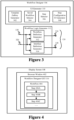
- FIG. 3 is a block diagram of workflow designer 106, according to an example embodiment.
- workflow designer 106 includes UI generator 110 and workflow logic generator 112.
- UI generator 110 includes a template gallery generator 302, a saved workflow selector 304, a step selector 306, and a step configuration UI generator 308.
- Workflow logic generator 112 includes a workflow definition generator 312 and an interface definition generator 314.
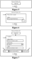
- FIG. 4 is a block diagram of display screen 108, illustrating an example of workflow designer GUI 116 displayed in browser window 402 on display screen 108, according to an example embodiment
- step 202 development of a workflow is initiated.
- workflow designer 106 may be invoked by a developer interacting with browser 136 at computing device 102.
- the developer may traverse a link or other network address directed to workflow designer 106 at server 134, to invoke workflow designer 106, causing workflow designer 106 to provide workflow GUI information 140 (e.g., one or more web pages, image content, etc.) to browser 136 to be displayed as workflow designer GUI 116 in display screen 108 in browser window 114.
- workflow GUI information 140 e.g., one or more web pages, image content, etc.
- the developer may open an existing workflow for further development, or may begin developing a new workflow.
- a displayed page of workflow designer GUI 116 may display a template gallery generated by template gallery generator 302.
- the template gallery may include a plurality of selectable workflow templates, each of which includes one or more pre-selected workflow steps that are suitable for further configuration by a developer.
- the workflow templates may be stored in workflow library 118, and accessed for display by workflow designer GUI 116.
- the developer may select one of the workflow templates for inclusion in their workflow, and may proceed with configuring the contents of the workflow template, and/or may add additional workflow steps to the workflow steps of the workflow template to generate a more complex workflow.
- steps 406A and 406B may have been included in a workflow template placed in workflow 404, and step 406C may have been subsequently added (e.g., via selection from a menu or other list of workflow steps).
- saved workflow selector 304 may enable the developer to select an existing, saved workflow to be opened for further editing in a displayed page of workflow designer GUI 116.
- the saved workflows may be stored in workflow library 118 or elsewhere.
- saved workflow selector 306 may display a list of saved workflows, may enable navigation to a saved workflow, and/or may provide another mechanism for selecting a saved workflow for editing. The developer may then proceed with further configuring the contents of the workflow, adding workflow steps, modifying workflow steps, removing workflow steps, or the like.
- a displayed page of workflow designer GUI 116 may provide a blank window, area or canvas to which one or more developer-selected workflow steps may be added, ordered and configured.
- Such blank window, area or canvas may be generated by UI generator 110 automatically or in response to some developer input or interaction.
- step 204 selection of one or more steps for inclusion in the workflow is enabled.
- step selector 306 may enable the developer to select workflow steps for inclusion in the workflow, and to order the steps.
- the workflow steps may be accessed by step selector 306 in workflow library 118.
- step selector 306 may display a menu of workflow steps, a scrollable and/or searchable list of available workflow steps, or may provide the workflow steps in another manner, and may enable the developer to select any number of workflow steps from the list for inclusion in the workflow.
- step selector 306 may enable a developer to select a step that is associated with a local application, such as Microsoft ® Outlook ® , or a network-based application, such as Facebook ® . Step selector 306 enables the steps to be chained together in a sequence, optionally with conditional steps, for inclusion in workflow logic 120.
- a local application such as Microsoft ® Outlook ®
- a network-based application such as Facebook ®
- step configuration UI generator 308 enables configuration of each workflow step in a workflow.
- Step configuration UI generator 308 accesses each selected workflow step in workflow library 118 to determine the configuration of the workflow step, including all of its input parameters and any other selections or information that a developer needs to provide to the workflow step to configure it.
- step configuration UI generator 308 may generate a UI that enables the developer to type, navigate to, use a pull-down menu, or otherwise enter input data into a text input box or other data entry element to configure (e.g., specify an input parameter of) a workflow step.
- the developer may configure an output parameter of a prior step to be input data for a workflow step.
- Step configuration UI generator 208 may enable data or other objects to be copied and pasted, dragged and dropped, or otherwise entered from elsewhere into data entry elements of a workflow step.
- workflow logic to implement the workflow is generated.
- workflow logic generator 112 is configured to package and generate workflow logic 120 based on constructed workflow information 138 when the developer indicates the workflow is finished, such as when the developer interacts with workflow designer GUI 116 to save the workflow.
- workflow logic generator 112 receives constructed workflow information 138. Constructed workflow information 138 indicates which workflow steps have been inserted into the workflow, their input parameter values, and their sequencing.
- Workflow logic generator 112 also receives selected workflow logic 320, which is the workflow logic for each workflow step of the workflow as indicated in constructed workflow information 138.
- workflow logic generator 112 retrieves workflow logic from workflow library 118 for each workflow step indicated in constructed workflow information 138, to receive selected workflow logic 320.
- Workflow logic generator 112 generates workflow logic 120 for the workflow based on constructed workflow information 138 and selected workflow logic 320.
- workflow logic generator 112 may generate workflow logic 120 in the form of an executable file, a zip file, or other form, which may be executed in a standalone fashion, may be executed in a browser, or may be executed in another manner, depending on the particular type of workflow being generated.
- workflow logic generator 112 may generate workflow logic 120 to include at least two components (e.g., files): workflow definition information 316 and interface definition information 318.
- Workflow definition information 316 includes information that defines the sequence and operation of the workflow of workflow logic (e.g., lists the workflow step operations and their ordering/sequencing) and includes the parameter values for the workflow.
- workflow definition information 316 may be generated to contain information in the format of a JSON (JavaScript object notation) file or in another form.
- Interface definition information 318 includes information that defines the interfaces/parameters (e.g., inputs and outputs) of the workflow steps of the workflow.
- interface definition information 318 may be generated to contain information in the format of a Swagger (a specification for REST (representational state transfer) web services) file or in another form.
- each workflow step may be represented in workflow library 118 as API (application programming interface) metadata in Swagger format, defining what are the inputs and outputs (parameters) of the workflow step, such that a service may be accessed according to the API definition.
- the operations in the workflow definition information 316 refer to the corresponding API metadata in the interface definition information 318 to provide a complete structure of a generated workflow (e.g., each sequenced workflow step/operation defined with parameter values in the workflow definition information 316 has a corresponding API, which is defined in the interface definition information 318).
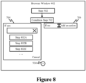
- FIGS. 5-8 show views of an exemplary workflow in various phases of development using a workflow designer GUI, according to example embodiments.
- each of FIGS. 5-8 shows browser window 402 displaying a corresponding view of workflow designer GUI 116 being used to develop a workflow.
- FIG. 5 shows browser window 402 including a workflow step 502 and an add interface 504.
- Workflow step 502 was selected by a developer to be a first step in a workflow.
- Add interface 504 e.g., a button or other GUI control
- a developer is enabled to select workflow step 502 from a list or library of steps, a template gallery, or elsewhere.
- a list, library, or gallery may include any number of workflow steps.
- the workflow steps may be associated with network-based applications mentioned elsewhere herein or otherwise known (e.g., Dropbox TM ), and/or with local applications mentioned elsewhere herein or otherwise known (e.g., Microsoft ® Outlook ® ).Each workflow step is configured to be plugged into the workflow.
- Each workflow step is configured with the appropriate logic and/or interface(s) to perform its respective function(s), which may include communicating with a local or remote application.
- a workflow step for transmitting a query to an application may be pre-configured in terms of how to properly transmit and format such a request to the application.
- a workflow step for receiving a response to a request may be pre-configured in terms of how to parse the response for desired response data.
- a developer of a workflow does not need to know how to write program code in a programming language, to interface with complex application interfaces (e.g., application programming interfaces (APIs)), or to understand network communication protocols, as the workflow steps are already set up.
- APIs application programming interfaces
- step 502 is configured to perform monitoring to determine if a file has been created in a particular folder identified by the developer in a text input box (e.g., by typing, clicking on a navigator indicated by ". . .”, etc.).
- a workflow step following workflow step 502 is triggered.
- workflow step 502 may be considered a trigger step in this example.
- workflow step 702 is a conditional step.
- logical elements may be selected for inclusion in a workflow, including arithmetic logic (e.g., summers, multipliers, etc.), conditional logic, etc., that operate based on variable values determined in earlier workflow steps.
- the condition of workflow step 702 enables the workflow to fork based on the determination of a condition (e.g., a variable value).
- the condition may include an object name, a relationship (e.g., a logical relationship, such as equal to, includes, not equal to, less than, greater than, etc.), and a value, which are all defined by the developer interacting with workflow step 702. Corresponding action steps may be performed depending on which way the workflow forks based on the condition.
- a relationship e.g., a logical relationship, such as equal to, includes, not equal to, less than, greater than, etc.
- a value which are all defined by the developer interacting with workflow step 702.
- Corresponding action steps may be performed depending on which way the workflow forks based on the condition.
- the object name may be selected (e.g., from a list of possibilities) to be a name of the created file of workflow step 502, the relationship may be "contains” (e.g., selected by a pull-down menu) and the value may be "dummyfile” (e.g., typed in by the developer).
- the condition evaluates to a "yes” condition if the file name contains "dummyfile,” which invokes first action workflow step 704, and evaluates to "no” condition if the file name does not contain "dummyfile,” which invokes second action workflow step 706.
- An action may be defined for one or both of the "yes” and "no” action workflow steps 704 and 706 by the developer, if desired.
- the developer interacts with action workflow step 704 to define an action.
- the developer is defining action workflow step 704 by selecting a workflow step via step selector 306.
- a list of workflow steps 802A, 802B, 802C is displayed, from which the developer can select a workflow step (e.g., by mouse click, etc.) to be performed for action workflow step 704.
- the workflow step can be a trigger step, an action step, or a condition step.
- the developer may configure the workflow step as described above.
- the developer may configure an action for workflow step 706, may add further workflow steps, etc., eventually being enabled to save the workflow.
- a workflow step such as first workflow step 502 may require credentials (e.g., a login and password) to access indicated data (e.g., to access a file at the location indicated in the text input box in FIG. 6 ).
- credentials e.g., a login and password
- the developer may be requested to provide credential information in association with first workflow step 502 so that when first workflow step 502 is performed during runtime, the data may be accessed.
- the credentials may be requested of a user during runtime.
- end users may execute workflows developed as described herein.
- an end user may interact with a GUI of the workflow, which may lead to workflow logic being executed.
- the workflow logic may execute locally (e.g., in a browser) and/or at a remote service (in "the cloud”).
- the workflow logic may access data of one or more local or network-accessible applications as was configured by the developer. Accordingly, the workflow performs its intended functions.
- FIG. 9 is a block diagram of a system 900 for executing a workflow that includes one or more workflow steps, according to an example embodiment.
- system 900 includes a computing device 902, first network-based application 124A, second network-based application 124B, and server 134.
- Computing device 902 includes a workflow application 904.
- Server 134 includes a workflow execution engine 906.
- System 900 is described as follows.
- First and second network-based applications 124A and 124B are each optionally present, and whether or not such applications are communicated with will depend on the configuration of workflow logic 120. Further network-based applications may be present and communicated with, depending on the configuration of workflow logic 120.
- Computing device 902 may be any type of stationary or mobile computing device described herein or otherwise known. Computing device 902 is configured to communicate with first and second network-based applications 124A and 124B and server 134 over network 126.
- workflows are executed at server 134 by workflow execution engine 906, and workflow application 904 is a UI application that enables a user at computing device 902 to interact with the executing workflows, such as by selecting and invoking the workflows, receiving communications from the executing workflows (e.g., messages, alerts, output data, etc.), providing requested input data to executing workflows, etc.
- workflow application 904 may be a workflow UI application associated with workflow execution engine 906 (e.g., workflow application 904 may be an extension of workflow execution engine 906) that may operate separate from or within a browser at computing device 902, or may be configured in another way.
- workflow execution engine 906 may load workflow logic 120 for a selected workflow (e.g., selected from a workflow library by a user), and may execute workflow logic 120 to execute the workflow.
- workflow application 904 may be configured to execute workflows at computing device 902. For instance, an end user of computing device 902 may interact with a user interface of workflow application 904 to select and invoke a particular workflow (e.g., selected from a workflow library).
- workflow logic 120 may operate separate from or in a browser at computing device 902, or may be configured in another way.
- workflow application 904 may load workflow logic 120 for a selected workflow (e.g., selected from a workflow library by a user), and may execute workflow logic 120 to execute the workflow.
- a first portion of workflow logic 120 may execute in workflow application 904 at computing device 902 and a second portion of workflow logic 120 may execute in workflow execution engine 906 at server 134 and/or elsewhere.
- FIG. 10 depicts a flowchart 1000 of a process for executing workflow logic 120 of a workflow, according to an example embodiment.
- Flowchart 1000 is described as follows with respect to system 900 of FIG. 9 for illustrative purposes.
- Flowchart 1000 begins with step 1002.
- the workflow is executed.
- an end user at computing device 902 may cause workflow logic 120 to be executed, such as by command line, by clicking/tapping or otherwise interacting with an icon representing the application, by selection in a browser, or in another manner.
- workflow logic 120 may execute in workflow application 904 at computing device 902 and/or in workflow execution engine 906 at server 134. When executed, the workflow steps of workflow logic 120 are performed in the configured sequence.
- one or more of the workflow steps may make calls to corresponding applications/services to perform their functions, such as local application 122 (to return data 132), network-based application 124A (to return data 130A), network-based application 124B (to return data 130B), and/or other local or network-based applications.
- applications/services such as local application 122 (to return data 132), network-based application 124A (to return data 130A), network-based application 124B (to return data 130B), and/or other local or network-based applications.
- step 1004 the workflow GUI is displayed.
- Step 1004 is optional, as in some embodiments, a GUI is not displayed for a workflow.
- the GUI may be displayed by workflow application 904 at computing device 902.
- the user may interact with the GUI by reviewing displayed data (e.g., from a file, database record, spreadsheet, or other data structure read by the workflow), by entering data into the GUI (e.g., by typing, by voice, etc.), and/or by interacting with one or more controls displayed by the GUI.
- step 1006 workflow logic is triggered based on an interaction with the workflow.
- Step 1006 is optional in cases where one or more workflow steps of a workflow require input from a user. In such cases, the user interacts with a control in a GUI of workflow application 904 associated with a workflow step of workflow logic 120 to provide information that triggers logic of the workflow step to operate.
- workflow logic 120 performs its functions, such as processing orders, tracking information, generating messages, processing documents to generate tasks or information, collecting feedback, and/or any other functions.
- step selector 306 of UI generator 110 may be invoked to present a developer with a list of steps, each of which may be selected for insertion into a workflow under development.
- step selector 306 is configured to provide the developer with a means for interacting with a search engine that can be used to identify workflow steps of interest to the developer. This enables the developer to quickly find useful and suitable workflow steps for developing her workflow.
- step selector 306 may be configured to provide a developer with access to this functionality within the context of a workflow designer GUI that concurrently displays a representation of the workflow currently being developed. Consequently, a developer can identify relevant workflow steps precisely when she needs them and without having to navigate away from the workflow representation.
- FIG. 11 is a block diagram of server 134 that includes workflow designer 106 and workflow library 118 (as previously discussed above in reference to FIG. 1 ). As shown in FIG. 11 , workflow designer 106 also includes a search engine 1102. As will be discussed below in reference to FIG. 12 , workflow designer 106 utilizes search engine 1102 to present a developer with a set of workflow steps for insertion into a workflow under development.
- FIG. 12 depicts a flowchart 1200 of a method performed by workflow designer 106 for searching for and presenting a developer with a set of workflow steps for insertion into a workflow under development.
- the method of flowchart 1200 begins at step 1202, in which input is accepted from a developer and is passed as a query to a search engine.
- This step may be performed, for example, by step selector 306, which receives input from a developer (e.g., text input by a developer) and passes the input as a query 1106 to search engine 1102.
- step selector 306 may provide a data entry element (e.g. a text input box) or other interactive GUI component via which a user can provide input.
- Step selector 306 may present the data entry element within a workflow designer GUI that displays a representation of the workflow currently being developed.
- the query is processed in a search engine to select one or more workflow steps from a library of workflow steps.
- This step may be performed, for example, by search engine 1102 which receives query 1106 and processes it to select one or more workflow steps from workflow library 118.
- search engine 1102 selects the workflow step(s) by analyzing workflow step metadata 1104 associated with each of the workflow steps stored in workflow library 118 to identify workflow steps that are relevant to query 1106.
- Workflow step metadata 1104 may include any type of structured or unstructured data concerning a workflow step.
- metadata may include a name or other identifier of the workflow step, a description of the workflow step, an identifier and/or description of a service that is utilized or referenced by the workflow step (e.g., Dropbox TM , Facebook ® , Outlook ® , or the like), a description and/or identifier of a trigger monitored for by the workflow step, or a description and/or identifier of an action performed by the workflow step.
- the metadata may include multiple terms that can be used to describe the same step, service, trigger, or action so as to enable matching against a diverse array of developer queries.
- search engine 1102 comprises a natural language search engine that is configured to use natural language processing to interpret queries expressed using normal terms in a user's language, without any special syntax or format.
- a natural language query may be expressed as a statement or a question.
- Such a natural language search engine may be capable of determining a user's intent based on the content of the query and provide highly-relevant workflow step suggestions.
- search engine 1102 may be configured to perform keyword searching, semantic searching, or any other type of searching known to persons skilled in the relevant art(s).
- the search engine provides an identifier of each of the workflow steps selected during step 1204. This step may be performed, for example, by search engine 1102, which provides workflow step identifiers 1108 to step selector 306.
- the identifiers comprise names of the selected workflow steps.
- each of the identifiers provided during step 1206 is presented to the developer and the developer is enabled to select any one of them.
- This step may entail, for example, step selector 306 presenting the identifiers to the developer in a menu that is displayed within a workflow designer GUI that displays a representation of the workflow currently being developed. The developer may be enabled to navigate or scroll up and down the menu to highlight and select a particular workflow step.
- a representation of the workflow step corresponding to the selected identifier is rendered as part of a workflow under development that is currently being displayed in the workflow designer GUI. This step may be performed, for example, by step selector 306, when the developer selects a particular workflow step identifier from the aforementioned menu.
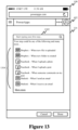
- FIGS. 13-15 show different views of workflow designer GUI 116 displayed within browser window 402 of display screen 108 in an example in which computing device 102 is a mobile computing device, such as a smart phone.
- workflow designer GUI 116 comprises a "New flow" screen that enables a developer to build a new workflow without starting from a template or saved workflow (i.e., from scratch).
- This screen includes features that enable the developer to generate or identify a trigger step that will initiate the workflow.
- the trigger step may be thought of as a workflow step that monitors for the occurrence of a particular event and, when it determines that the particular event has occurred, triggers the execution of subsequent steps of the workflow.
- workflow designer GUI 116 includes a menu 1304 of selectable trigger steps such as “Dropbox - When new file is uploaded,” “Dropbox - When new folder is created,” “Facebook - When I upload a photo,” “Facebook - When I upload a post,” “Facebook - When someone comments on my post,” “Outlook - When I send an email” and “Outlook - When I receive an email.”
- a developer may interact with (point and click with a mouse, touch via a touch screen, etc.) any of these example trigger steps to select it as the initial step in the workflow.
- the developer may type text into a data entry element 1302 (in this case, a text box) that appears in workflow designer GUI 116 and includes the text "Start typing your first step".
- a data entry element 1302 in this case, a text box
- search engine 1102 may only search for workflow steps that qualify as trigger steps. For subsequent steps of the workflow, a broader set of operations may be searched.
- FIG. 14 shows workflow designer GUI 116 after a developer has entered the text "new file" into data entry element 1302. This text is provided as a query to search engine 1102. Based on the query, search engine 1102 selects a set of workflow steps (in this case, trigger steps) that are relevant to the query. Search engine 1102 returns identifiers of the selected workflow steps (in this case, icons and names) and such identifiers are displayed in a menu 1404. As shown in FIG.
- the selected steps include "Box - When a file is created,” “Dropbox - When a file is created,” “OneDrive - When a file is crated,” “OneDrive for Business - When a file is created,” and “SharePoint Online - When a file is created.”
- a developer may interact with any of these example trigger steps to select it as the initial step in the workflow.
- the developer can then initiate the addition of a second step to the workflow.
- This feature is illustrated by FIG. 15 .
- the developer can add another step (e.g., an action or condition). It will be assumed for the sake of this example that the developer selected an action as the second step of the workflow.
- the developer When the developer selects an action as the next step, the developer is presented with a menu 1504 of selectable trigger and action steps, as well as a data entry element 1502 that includes the text "What would you like to do next?"
- the developer may type text into data entry element 1502 and such text will be provided as a query to search engine 1102 and used to find workflow steps that can follow the trigger step in the workflow currently being developed.
- search engine 1102 In this way, the developer may be presented with access to the search engine functionality each time the developer wants to add a new step to the workflow.
- Such functionality is advantageously presented within the same workflow designer GUI 116 used to display the workflow under development, which means that the developer need not navigate away from the workflow under development to perform the search.
- a text box is shown as being the means for providing input to search engine 1102
- the input can be provided by speaking into a microphone.
- voice-based input may then be submitted to an entity executing on server 134 (or on a computing device that is communicatively connected thereto) that converts the voice-based input to text.
- the text returned by this entity may then be submitted to search engine 1102. In this way, voice-based natural language searching may be achieved.
- search engine 1102 operates by analyzing metadata associated with various workflow steps stored in workflow library 118 to identify workflow steps that are relevant to a developer query.
- the metadata associated with a particular workflow step may be input by another developer.
- workflow development system 100 may provide a GUI via which a developer can input metadata that is to be associated with one or more operations.
- the developer provides the metadata at the time the developer registers an API for use with one or more workflows, as part of the API registration process.
- the API may be, for example and without limitation, an API for an online service that can be utilized or referenced by a step in an automated workflow.
- the metadata associated with a particular workflow step may be provided by multiple developers.
- workflow development system 100 may provide a GUI by which multiple developers can voluntarily "tag" (e.g., provide descriptive terms for) the various workflow steps that can be included in a workflow. This enables a "crowd-sourcing" approach to generating the metadata that can then be used to facilitate the search functionality.
- the techniques described above for identifying relevant workflow steps can be adapted such that they can be used by a developer to find workflow templates or saved workflows.
- text or other user input provided by a developer via workflow designer GUI 116 can be provided as a query to a search engine.
- the search engine may analyze metadata associated with workflow templates or saved workflows to select workflow templates or saved workflows that are relevant to the query. Access to the selected workflow templates or saved workflows may then be provided to the developer, e.g., via the same workflow designer GUI 116.
- workflow development system 100 is configured to automatically generate a name and/or graphical representation (e.g., an icon) for a workflow.
- the name and/or graphical representation is generated, for example, based on steps included in the workflow and/or on one or more services that are referenced by the workflow.
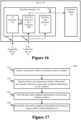
- FIG. 16 is a block diagram of server 134 that includes workflow designer 106 and workflow library 118 (as previously discussed above in reference to FIG. 1 ).
- workflow designer 106 includes UI generator 110, workflow logic generator 112 and a workflow name and icon generator 1602.
- workflow name and icon generator 1602 is configured to automatically generate a name and graphical representation for a workflow.
- FIG. 17 depicts a flowchart 1700 of a method for automatically generating a name and graphical representation for a workflow.
- the method of flowchart 1700 begins at step 1702, in which constructed workflow information about a workflow is received. This step may be performed, for example, by workflow name and icon generator 1602, which (as shown in FIG. 16 ) receives constructed workflow information 138 from browser 136 executing on computing device 102.
- constructed workflow information 138 comprises the selected workflow steps, corresponding configuration information, and workflow step sequence information for a workflow currently being developed on computing device 102.
- Such constructed workflow information 138 is sent to workflow logic generator 112 to facilitate the generation of workflow logic 120 in a manner previously described.
- constructed workflow information 138 is also provided to workflow name and icon generator 1602.
- a name and/or graphical representation is automatically determined for the workflow based at least on the constructed workflow information.
- This step may be performed, for example by workflow name and icon generator 1602, which automatically generates a name and/or graphical representation 1604 for the workflow currently being developed on computing device 102 based at least on the constructed workflow information received during step 1702.
- workflow name and icon generator 1602 may generate name and/or graphical representation 1604 of the workflow currently being developed based on one or more of one or more steps included in the workflow (and the order thereof), one or more services that are referenced by the workflow (and the order in which such services are referenced), one or more trigger events that are monitored for by the workflow, one or more conditions included in the workflow, one or more actions included in the workflow, or the like.
- a workflow name words that describe or relate to these aspects of the workflow are combined to generate a suitable name for the workflow.
- images that describe or relate to these aspects of the workflow are combined to generate a suitable graphical representation for the workflow.
- a graphical representation for a workflow is generated by combining icons associated with one or more steps included in the workflow and/or services referenced or interacted with by the workflow.
- the name and/or graphical representation that was generated for the workflow is stored in association with the workflow. This step may be performed, for example, by workflow name and icon generator 1602 which may store name and/or graphical representation 1604 that was generated for a workflow in association with that workflow in workflow library 118.
- the name and/or graphical representation that was generated for the workflow is provided for display within a workflow designer GUI.
- This step may be performed, for example, by workflow name and icon generator 1602 which may provide name and/or graphical representation 1604 to UI generator 110 so that UI generator 110 can pass name and/or graphical representation 1604 to browser 136 as part of workflow GUI information 140.
- Browser 136 may cause name and/or graphical representation 1604 to be displayed within workflow designer GUI 116 within browser window 114.
- the automatically-generated name of the workflow may be displayed as a default workflow name within a text box or other data entry element that is used to enter names for workflows, such that a developer can either accept the name or overwrite it with a new one.
- the automatically-generated name and graphical representation is displayed within a menu of saved workflows that a developer may interact within in order to activate, deactivate, edit, delete or perform other operations with respect to one or more of the saved workflows.
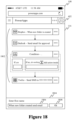
- FIGS. 18 and 19 show views of a workflow designer GUI 116 displayed within browser window 402 of display screen 108 in an embodiment in which computing device 102 is a mobile computing device, such as a smart phone.
- workflow designer GUI 116 displays a workflow 1802 that a developer has recently constructed using techniques that were described previously herein.
- workflow designer GUI 116 also includes a save workflow dialog box 1804.
- Save workflow dialog box 1804 includes a data entry element 1806 (in this case, a text box) into which a developer may enter a name for the newly-constructed workflow as well as an activation button 1808 (labelled "OK") that will cause the newly-constructed workflow to be saved with the name entered into data entry element 1806.
- UI generator 110 may cause data entry element 1806 to be pre-populated with a system-generated name for workflow 1802, wherein the system-generated name is generated using the method of flowchart 1700 as described above.
- the system-generated name for workflow 1802 may be "When new folder is created send email.”
- the developer can accept the system-generated name by interacting with activation button 1808 to save the workflow with the system-generated name, or may decide to alter the name. In the latter case, the developer may interact with data entry element 1806 to modify or overwrite the system-generated name before saving the workflow.
- workflow designer GUI 116 displays a menu of saved workflows that a developer may interact within in order to activate, deactivate, edit, delete or perform other operations with respect to one or more of the saved workflows.
- workflow 1802 may be represented by an icon 1902 and a name 1904, both of which may be automatically generated using the method of flowchart 1700 as described above.
- workflow name and icon generator 1602 may automatically generate an icon for a workflow by combining icons associated with one or more steps included in the workflow and/or services referenced or interacted with by the workflow.
- FIG. 19 is a combination of an icon 1906 associated with DropBox TM , an icon 1910 associated with Microsoft ® Outlook ® , and an icon 1912 associated with Twilio ® .Each of these are services referenced by workflow 1802 and thus have been combined into representative icon 1902. Furthermore, an icon 1908 has been incorporated into icon 1902 that represents the condition step within workflow 1802. However, this is only an example, and a wide variety of techniques may be used to automatically generate an icon or other graphical representation of a workflow.
- workflow designer 106 generates workflow designer GUI 116 that enables a developer to configure a workflow step within a workflow under development, wherein such configuration includes specifying a value of an input parameter for the workflow step.
- workflow designer GUI 116 enables a developer to easily specify a value of an input parameter of a second workflow step to include a value of an output parameter of a first workflow step in the same workflow.
- workflow designer GUI 116 represents output parameters of a first workflow step of a workflow under development as user-interactive objects. These objects can be easily interacted with (e.g., clicked on or dragged and dropped) by a developer to cause the objects to be inserted into a data entry element (e.g. a text box) that is used to specify a value for an input parameter of a second workflow step of the workflow under development.
- a data entry element e.g. a text box
- executable logic representing the first and second workflow steps is generated, the aforementioned insertion of the objects into the data entry element has the effect of causing the value of the input parameter of the second workflow step to be defined to include the values of the output parameters that correspond to the inserted objects.
- FIG. 20 depicts a flowchart 2000 of a method for defining a value of an input parameter of a second workflow step based on user interaction with one or more user-interactive objects that respectively represent one or more output parameters of a first workflow step within a workflow designer GUI, in accordance with an example.
- the method of flowchart 2000 may be performed, for example by workflow designer 106 (or various components thereof) as previously described.
- FIGS. 21-23 each of which shows a different view of workflow designer GUI 116 displayed within browser window 402 of display screen 108 in an example in which computing device 102 is a mobile computing device, such as a smart phone.
- the method of flowchart 2000 begins at step 2002, in which a user selection of a first workflow step to be included in a workflow under development is received.
- workflow designer 106 may receive user input that indicates that a developer has selected a first workflow step "Dropbox - When a file is created.” Such input may be received via a step selection tool that is displayed within a workflow designer GUI, as was previously described, or in some other manner.
- a graphical representation of the first workflow step is presented in a workflow designer GUI.
- workflow designer 106 may cause a graphical representation 2102 of the first workflow step "Dropbox - When a file is created” to be rendered within workflow designer GUI 116.
- "Dropbox - When a file is created” comprises a trigger step that monitors to determine when a file has been created in a particular Dropbox ® folder.
- workflow designer GUI 116 includes a data entry element 2104 (in this case, a text box) and a file browser activator 2106, each of which can be used by the developer to specify or select an input parameter for this step.
- these mechanisms enable the developer to specify or select the name of the Dropbox ® folder to be monitored for the file creation.
- the developer has specified the folder "Dropbox > Backup.”
- a user selection of a second workflow step to be included in the workflow under development is received.
- workflow designer 106 may receive user input that indicates that the developer has selected a second workflow step "Outlook - Send email.” Such input may be received via a step selection tool that is displayed within a workflow designer GUI, as was previously described, or in some other manner.
- the step selection tool may be displayed when the developer interacts with an action button 2108, indicating that the developer wishes to add an action (as opposed to a condition) as the next step in the workflow under development.
- a graphical representation of the second workflow step is presented in the workflow designer GUI.
- workflow designer 106 may cause a graphical representation 2202 of the second workflow step "Outlook - Send email” to be rendered within workflow designer GUI 116.
- "Outlook - Send email” comprises an action step that is carried out when a trigger event is detected by trigger step "Dropbox - When file is created.”
- the graphical representation of the second workflow step comprises a data entry element into which a user can input a value of an input parameter of the second workflow step.
- graphical representation 2202 of second workflow step "Outlook - Send email” includes a first data entry element 2204, a second data entry element 2206, and a third data entry element 2208. The developer may interact with each of these data entry elements to specify a value of a corresponding input parameter of the second workflow step.
- first data entry element 2204 to specify an intended recipient of an email to be sent by the second workflow step
- second data entry element 2206 to specify a subject line for the email
- third data entry element 2208 to specify text to be included in the body of the email.
- the developer has specified (e.g., by typing text into data entry element 2204) that the value of the e-mail recipient input parameter is "msmith@domain.com".
- step 2010 one or more user-interactive objects are presented in the workflow designer GUI that respectively represent one or more output parameters of the first workflow step.
- workflow designer 106 causes a user-interactive object 2210, a user-interactive object 2212, a user-interactive object 2214, a user-interactive object 2216 and a user-interactive object 2218 to be presented within graphical representation 2202 of the workflow step "Outlook - Send email" displayed within workflow designer GUI 116.
- Each of these user-interactive objects respectively represent a corresponding output parameter of the first workflow step "Dropbox - When a file is created."
- user-interactive object 2210 represents a file content output parameter of the first workflow step
- user-interactive object 2212 represents a file identifier output parameter of the first workflow step
- user-interactive object 2214 represents a file name output parameter of the first workflow step
- user-interactive object 2216 represents a file entity tag output parameter of the first workflow step
- user-interactive object 2218 represents a file path output parameter of the first workflow step.
- the developer may interact with each of user-interactive objects 2210, 2212, 2214, 2216, 2218 to cause the corresponding user-interactive object to be copied into second data entry element 2206.
- the developer may simply click on a user-interactive object using a mouse, touch a user-interactive object via a touch screen, or the like.
- the developer may drag and drop a particular user-interactive object into second data entry element 2206.
- Still other forms of user-interaction may be performed that will cause a user-interactive object to be copied into second data entry element 2206.
- step 2012 This functionality is represented in step 2012 of flowchart 2000.
- the particular user-interactive object in response to user interaction with a particular user-interactive object from among the one or more user-interactive objects, the particular user-interactive object is copied into the data entry element.
- a user-interactive object 2302 which is a copy of user-interactive object 2214 has been included in data entry element 2206.
- the developer also input some text (“was created in your Dropbox folder") into data entry element 2206, following user-interactive object 2302.
- step 2012 executable workflow logic is generated corresponding to at least the first workflow step and the second workflow step, wherein the generating the executable workflow logic comprises defining the value of the input parameter of the second workflow to include a value of a particular output parameter of the first workflow step that corresponds to the particular user-interactive object that was copied into the data entry element.
- workflow designer 106 generates executable workflow logic (e.g., via workflow logic generator 112 as previously described) that corresponds to at least the first workflow step "Dropbox - When a file is created” and the second workflow step "Outlook - Send email”, wherein generating such logic includes defining the value of the "subject” input parameter of the second workflow step “Outlook - Send email” to include the value of the "file name” output parameter of the first workflow step "Dropbox - When a file is created” that corresponds to user-interactive object 2214 that was copied into data entry element 2206.
- executable workflow logic e.g., via workflow logic generator 112 as previously described
- FIG. 23 further illustrates how user-interactive objects 2304, 2306, 2308, 2310 and 2312, each of which represents an output parameter of first workflow step "Dropbox - When a file is created", can be easily interacted with by a developer to insert such output parameters into the input parameter "Body" of second workflow step "Outlook - Send email.”
- the developer has interacted with user-interactive object 2308 ("file name”) and user-interactive object 2312 ("file path”), thereby causing a copy thereof (user-interactive object 2314 and user-interactive object 2316, respectively) to be inserted into data entry element 2208.
- the graphical representations of the first and second workflow steps are presented in the workflow designer GUI in response to a developer's selection of each of those steps.
- graphical representations may be presented in response to other developer actions as well.
- graphical representations of workflow steps may also be presented within the workflow designer GUI in response to a developer selecting or loading a particular workflow template or saved workflow for editing and configuration.
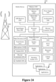
- FIG. 24 is a block diagram of an exemplary mobile device 2402 that may implement embodiments described herein.
- mobile device 2402 may be used to implement computing device 102 of FIG. 1 or computing device 902 of FIG. 9 .
- mobile device 2402 includes a variety of optional hardware and software components. Any component in mobile device 2402 can communicate with any other component, although not all connections are shown for ease of illustration.
- Mobile device 2402 can be any of a variety of computing devices (e.g., cell phone, smart phone, handheld computer, Personal Digital Assistant (PDA), etc.) and can allow wireless two-way communications with one or more mobile communications networks 2404, such as a cellular or satellite network, or with a local area or wide area network.
- mobile communications networks 2404 such as a cellular or satellite network, or with a local area or wide area network.
- Mobile device 2402 can include a controller or processor 2410 (e.g., signal processor, microprocessor, ASIC, or other control and processing logic circuitry) for performing such tasks as signal coding, data processing, input/output processing, power control, and/or other functions.
- An operating system 2412 can control the allocation and usage of the components of mobile device 2402 and provide support for one or more application programs 2414 (also referred to as "applications" or "apps").
- Application programs 2414 may include common mobile computing applications (e.g., e-mail applications, calendars, contact managers, web browsers, messaging applications) and any other computing applications (e.g., word processing applications, mapping applications, media player applications).
- Mobile device 2402 can include memory 2420.
- Memory 2420 can include non-removable memory 2422 and/or removable memory 2424.
- Non-removable memory 2422 can include RAM, ROM, flash memory, a hard disk, or other well-known memory devices or technologies.
- Removable memory 2424 can include flash memory or a Subscriber Identity Module (SIM) card, which is well known in GSM communication systems, or other well-known memory devices or technologies, such as "smart cards.”
- SIM Subscriber Identity Module
- Memory 2420 can be used for storing data and/or code for running operating system 2412 and application programs 2414.
- Example data can include web pages, text, images, sound files, video data, or other data to be sent to and/or received from one or more network servers or other devices via one or more wired or wireless networks.
- Memory 2420 can be used to store a subscriber identifier, such as an International Mobile Subscriber Identity (IMSI), and an equipment identifier, such as an International Mobile Equipment Identifier (IMEI). Such identifiers can be transmitted to a network server to identify users and equipment.
- IMSI International Mobile Subscriber Identity
- IMEI International Mobile Equipment Identifier
- Mobile device 2402 can support one or more input devices 2430, such as a touch screen 2432, a microphone 2434, a camera 2436, a physical keyboard 2438 and/or a trackball 2440 and one or more output devices 2450, such as a speaker 2452 and a display 2454.
- input devices 2430 such as a touch screen 2432, a microphone 2434, a camera 2436, a physical keyboard 2438 and/or a trackball 2440 and one or more output devices 2450, such as a speaker 2452 and a display 2454.
- Other possible output devices can include piezoelectric or other haptic output devices. Some devices can serve more than one input/output function.
- touch screen 2432 and display 2454 can be combined in a single input/output device.
- Input devices 2430 can include a Natural User Interface (NUI).
- NUI Natural User Interface
- Wireless modem(s) 2460 can be coupled to antenna(s) (not shown) and can support two-way communications between processor 2410 and external devices, as is well understood in the art.
- Modem(s) 2460 are shown generically and can include a cellular modem 2466 for communicating with the mobile communication network 2404 and/or other radio-based modems (e.g., Bluetooth 2464 and/or Wi-Fi 2462).
- At least one of wireless modem(s) 2460 is typically configured for communication with one or more cellular networks, such as a GSM network for data and voice communications within a single cellular network, between cellular networks, or between the mobile device and a public switched telephone network (PSTN).
- GSM Global System for Mobile communications
- PSTN public switched telephone network
- Mobile device 2402 can further include at least one input/output port 2480, a power supply 2482, a satellite navigation system receiver 2484, such as a Global Positioning System (GPS) receiver, an accelerometer 2486, and/or a physical connector 2490, which can be a USB port, IEEE 1394 (FireWire) port, and/or RS-232 port.
- GPS Global Positioning System
- the illustrated components of mobile device 2402 are not required or all-inclusive, as any components can be deleted and other components can be added as would be recognized by one skilled in the art.
- mobile device 2402 is configured to implement any of the above-described features of workflow development system 100.
- Computer program logic for performing the functions of these devices may be stored in memory 2420 and executed by processor 2410.
- FIG. 25 depicts an example processor-based computer system 2500 that may be used to implement various embodiments described herein.
- system 2500 may be used to implement computing device 102 or server 134 as described above in reference to FIG. 1 , or computing device 902 as described above in reference to FIG. 9 .
- System 2500 may also be used to implement any of the steps of any of the flowcharts of FIGS. 2 , 10 , 12 , 17 and 20 as described above.
- the description of system 2500 provided herein is provided for purposes of illustration, and is not intended to be limiting. Embodiments may be implemented in further types of computer systems, as would be known to persons skilled in the relevant art(s).
- system 2500 includes a processing unit 2502, a system memory 2504, and a bus 2506 that couples various system components including system memory 2504 to processing unit 2502.
- Processing unit 2502 may comprise one or more circuits, microprocessors or microprocessor cores.
- Bus 2506 represents one or more of any of several types of bus structures, including a memory bus or memory controller, a peripheral bus, an accelerated graphics port, and a processor or local bus using any of a variety of bus architectures.
- System memory 2504 includes read only memory (ROM) 2508 and random access memory (RAM) 2510.
- ROM read only memory
- RAM random access memory
- a basic input/output system 2512 (BIOS) is stored in ROM 2508.
- System 2500 also has one or more of the following drives: a hard disk drive 2514 for reading from and writing to a hard disk, a magnetic disk drive 2516 for reading from or writing to a removable magnetic disk 2518, and an optical disk drive 2520 for reading from or writing to a removable optical disk 2522 such as a CD ROM, DVD ROM, BLU-RAY TM disk or other optical media.
- Hard disk drive 2514, magnetic disk drive 2516, and optical disk drive 2520 are connected to bus 2506 by a hard disk drive interface 2524, a magnetic disk drive interface 2526, and an optical drive interface 2528, respectively.
- the drives and their associated computer-readable media provide nonvolatile storage of computer-readable instructions, data structures, program modules and other data for the computer.
- a hard disk a removable magnetic disk and a removable optical disk
- other types of computer-readable memory devices and storage structures can be used to store data, such as flash memory cards, digital video disks, random access memories (RAMs), read only memories (ROM), and the like.
- program modules may be stored on the hard disk, magnetic disk, optical disk, ROM, or RAM. These program modules include an operating system 2530, one or more application programs 2532, other program modules 2534, and program data 2536.
- the program modules may include computer program logic that is executable by processing unit 2502 to perform any or all of the functions and features of computing device 102 or server 134 as described above in reference to FIG. 1 , or computing device 902 as described above in reference to FIG. 9 .
- the program modules may also include computer program logic that, when executed by processing unit 2502, causes processing unit 2502 to perform any of the steps of any of the flowcharts of FIGS. 2 , 10 , 12 , 17 and 20 as described above.
- a user may enter commands and information into system 2500 through input devices such as a keyboard 2538 and a pointing device 2540 (e.g., a mouse).
- Other input devices may include a microphone, joystick, game controller, scanner, or the like.
- a touch screen is provided in conjunction with a display 2544 to allow a user to provide user input via the application of a touch (as by a finger or stylus for example) to one or more points on the touch screen.
- processing unit 2502 through a serial port interface 2542 that is coupled to bus 2506, but may be connected by other interfaces, such as a parallel port, game port, or a universal serial bus (USB).
- Such interfaces may be wired or wireless interfaces.
- Display 2544 is connected to bus 2506 via an interface, such as a video adapter 2546.
- system 2500 may include other peripheral output devices (not shown) such as speakers and printers.
- System 2500 is connected to a network 2548 (e.g., a local area network or wide area network such as the Internet) through a network interface 2550, a modem 2552, or other suitable means for establishing communications over the network.
- a network 2548 e.g., a local area network or wide area network such as the Internet
- modem 2552 or other suitable means for establishing communications over the network.
- Modem 2552 which may be internal or external, is connected to bus 2506 via serial port interface 2542.
- computer program medium As used herein, the terms “computer program medium,” “computer-readable medium,” and “computer-readable storage medium” are used to generally refer to memory devices or storage structures such as the hard disk associated with hard disk drive 2514, removable magnetic disk 2518, removable optical disk 2522, as well as other memory devices or storage structures such as flash memory cards, digital video disks, random access memories (RAMs), read only memories (ROM), and the like.
- Such computer-readable storage media are distinguished from and non-overlapping with communication media (do not include communication media).
- Communication media typically embodies computer-readable instructions, data structures, program modules or other data in a modulated data signal such as a carrier wave.
- modulated data signal means a signal that has one or more of its characteristics set or changed in such a manner as to encode information in the signal.
- communication media includes wireless media such as acoustic, RF, infrared and other wireless media. Embodiments are also directed to such communication media.
- computer programs and modules may be stored on the hard disk, magnetic disk, optical disk, ROM, or RAM. Such computer programs may also be received via network interface 2550, serial port interface 2542, or any other interface type. Such computer programs, when executed or loaded by an application, enable system 2500 to implement features of embodiments discussed herein. Accordingly, such computer programs represent controllers of the system 2500.
- Embodiments are also directed to computer program products comprising software stored on any computer useable medium. Such software, when executed in one or more data processing devices, causes a data processing device(s) to operate as described herein.
- Embodiments may employ any computer-useable or computer-readable medium, known now or in the future.
- Examples of computer-readable mediums include, but are not limited to memory devices and storage structures such as RAM, hard drives, floppy disks, CD ROMs, DVD ROMs, zip disks, tapes, magnetic storage devices, optical storage devices, MEMs, nanotechnology-based storage devices, and the like.
- system 2500 may be implemented as hardware logic/electrical circuitry or firmware.
- one or more of these components may be implemented in a system-on-chip (SoC).
- SoC may include an integrated circuit chip that includes one or more of a processor (e.g., a microcontroller, microprocessor, digital signal processor (DSP), etc.), memory, one or more communication interfaces, and/or further circuits and/or embedded firmware to perform its functions.
- a processor e.g., a microcontroller, microprocessor, digital signal processor (DSP), etc.
Landscapes
- Engineering & Computer Science (AREA)
- Theoretical Computer Science (AREA)
- Business, Economics & Management (AREA)
- General Engineering & Computer Science (AREA)
- Software Systems (AREA)
- Human Resources & Organizations (AREA)
- Physics & Mathematics (AREA)
- General Physics & Mathematics (AREA)
- Economics (AREA)
- Entrepreneurship & Innovation (AREA)
- Strategic Management (AREA)
- Marketing (AREA)
- Educational Administration (AREA)
- Game Theory and Decision Science (AREA)
- Development Economics (AREA)
- Operations Research (AREA)
- Quality & Reliability (AREA)
- Tourism & Hospitality (AREA)
- General Business, Economics & Management (AREA)
- Human Computer Interaction (AREA)
- Management, Administration, Business Operations System, And Electronic Commerce (AREA)
- User Interface Of Digital Computer (AREA)
- Stored Programmes (AREA)
Claims (4)
- Verfahren (1700) in einer Rechenvorrichtung zum automatischen Generieren eines Namens für einen Arbeitsablauf in Entwicklung in einem Arbeitsablaufentwicklungssystem, umfassend:Empfangen (1702) konstruierter Arbeitsablaufinformationen über den Arbeitsablauf in Entwicklung, wobei die konstruierten Arbeitsablaufinformationen Informationen über Arbeitsablaufschritte, eine Konfiguration jedes der Arbeitsablaufschritte und Sequenzinformationen für die Arbeitsablaufschritte beinhalten;basierend mindestens auf den konstruierten Arbeitsablaufinformationen, automatisches Bestimmen (1704) eines Namens für den Arbeitsablauf in Entwicklung, wobei der Name automatisch durch Kombinieren von Wörtern, die sich auf einen oder mehrere Schritte beziehen, die in dem Arbeitsablauf in Entwicklung beinhaltet sind, und eine Reihenfolge des einen oder der mehreren Schritte bestimmt wird, die in dem Arbeitsablauf in Entwicklung beinhaltet sind, und/oder wobei der Name automatisch durch Kombinieren von Wörtern, die sich auf einen oder mehrere Dienste beziehen, die durch den Arbeitsablauf in Entwicklung referenziert werden, und eine Reihenfolge, in der der eine oder die mehreren Dienste durch den Arbeitsablauf in Entwicklung referenziert werden, bestimmt wird;Speichern (1706) des Namens in Verbindung mit dem Arbeitsablauf in Entwicklung; undBereitstellen (1708) des Namens zur Anzeige innerhalb einer grafischen Benutzeroberfläche, GUI, des Arbeitsablaufentwicklungssystems;automatisches Generieren (1704) einer grafischen Darstellung für den Arbeitsablauf in Entwicklung, basierend mindestens auf den konstruierten Arbeitsablaufinformationen, wobei die grafische Darstellung automatisch durch Kombinieren von Symbolen generiert wird, die dem einen oder den mehreren Diensten zugeordnet sind, die von dem Arbeitsablauf referenziert werden oder mit denen der Arbeitsablauf interagiert;Speichern (1706) der grafischen Darstellung in Verbindung mit dem Arbeitsablauf in Entwicklung; undBereitstellen (1708) der grafischen Darstellung zur Anzeige innerhalb der GUI des Arbeitsablaufentwicklungssystems,wobei das Bereitstellen des Namens und der grafischen Darstellung zur Anzeige innerhalb der GUI des Arbeitsablaufentwicklungssystems Bereitstellen des Namens und der grafischen Darstellung innerhalb eines Menüs gespeicherter Arbeitsabläufe umfasst, wobei Benutzerinteraktion innerhalb des Menüs Durchführen von Operationen in Bezug auf die gespeicherten Arbeitsabläufe ermöglicht.
- Verfahren nach Anspruch 1, wobei der Name basierend auf mindestens einem des Folgenden automatisch bestimmt wird:einem oder mehreren Triggerereignissen, die von dem Arbeitsablauf in Entwicklung überwacht werden;einer oder mehreren Bedingungen, die in dem Arbeitsablauf in Entwicklung beinhaltet sind; odereiner oder mehreren Aktionen, die in dem Arbeitsablauf in Entwicklung beinhaltet sind.
- Verfahren nach Anspruch 1, wobei Bereitstellen des Namens zur Anzeige innerhalb der GUI des Arbeitsablaufentwicklungssystems Vorausfüllen eines Dateneingabefelds der GUI des Arbeitsablaufentwicklungssystems umfasst, wobei das Dateneingabefeld betreibbar ist, um einen benutzerspezifizierten Namen für den Arbeitsablauf in Entwicklung zu empfangen.
- Computerlesbares Speichermedium mit darauf gespeicherten computerausführbaren Anweisungen, die, wenn von einem Prozessor ausgeführt, das Verfahren nach einem der Ansprüche 1 bis 3 durchführen.
Applications Claiming Priority (3)
| Application Number | Priority Date | Filing Date | Title |
|---|---|---|---|
| US201562258851P | 2015-11-23 | 2015-11-23 | |
| US15/188,407 US10528327B2 (en) | 2015-11-23 | 2016-06-21 | Workflow development system with ease-of-use features |
| PCT/US2016/062122 WO2017091387A2 (en) | 2015-11-23 | 2016-11-16 | Workflow development system with ease-of-use features |
Publications (2)
| Publication Number | Publication Date |
|---|---|
| EP3380930A2 EP3380930A2 (de) | 2018-10-03 |
| EP3380930B1 true EP3380930B1 (de) | 2023-06-07 |
Family
ID=58719679
Family Applications (1)
| Application Number | Title | Priority Date | Filing Date |
|---|---|---|---|
| EP16805942.6A Active EP3380930B1 (de) | 2015-11-23 | 2016-11-16 | Entwicklungssystem für arbeitsablauf mit benutzerfreundlichen funktionen |
Country Status (4)
| Country | Link |
|---|---|
| US (4) | US10528327B2 (de) |
| EP (1) | EP3380930B1 (de) |
| CN (1) | CN108292206B (de) |
| WO (2) | WO2017091387A2 (de) |
Families Citing this family (66)
| Publication number | Priority date | Publication date | Assignee | Title |
|---|---|---|---|---|
| US10101976B2 (en) * | 2015-04-30 | 2018-10-16 | OpenMethods, Inc. | Method, system and apparatus for visual programming of interaction workflows for omni-channel customer contact centers with integrated customer relationship management |
| US10528327B2 (en) | 2015-11-23 | 2020-01-07 | Microsoft Technology Licensing Llc | Workflow development system with ease-of-use features |
| US10423393B2 (en) * | 2016-04-28 | 2019-09-24 | Microsoft Technology Licensing, Llc | Intelligent flow designer |
| US10331416B2 (en) | 2016-04-28 | 2019-06-25 | Microsoft Technology Licensing, Llc | Application with embedded workflow designer |
| US11169823B2 (en) * | 2016-09-15 | 2021-11-09 | Oracle International Corporation | Process initiation |
| US11630708B2 (en) * | 2016-09-16 | 2023-04-18 | Oracle International Corporation | OSN/PCS collaboration mechanism integration |
| USD811426S1 (en) * | 2016-09-21 | 2018-02-27 | Uipco, Llc | Display panel or portion thereof with graphical user interface |
| USD810770S1 (en) * | 2016-09-21 | 2018-02-20 | Uipco, Llc | Display panel or portion thereof with graphical user interface |
| USD810771S1 (en) * | 2016-09-22 | 2018-02-20 | Adp, Llc | Display screen with animated graphical user interface |
| USD821425S1 (en) | 2016-09-26 | 2018-06-26 | General Electric Company | Display screen or portion thereof with graphical user interface |
| US10152356B2 (en) | 2016-12-07 | 2018-12-11 | Vmware, Inc. | Methods and apparatus for limiting data transferred over the network by interpreting part of the data as a metaproperty |
| US10552180B2 (en) | 2016-12-07 | 2020-02-04 | Vmware, Inc. | Methods, systems, and apparatus to trigger a workflow in a cloud computing environment |
| US11481239B2 (en) | 2016-12-07 | 2022-10-25 | Vmware, Inc. | Apparatus and methods to incorporate external system to approve deployment provisioning |
| JP6939105B2 (ja) * | 2017-06-09 | 2021-09-22 | 富士フイルムビジネスイノベーション株式会社 | 情報処理装置及びプログラム |
| CN108428092B (zh) * | 2017-08-03 | 2020-12-04 | 平安科技(深圳)有限公司 | 一种业务流程展示方法、装置及设备 |
| US11379565B2 (en) | 2017-10-02 | 2022-07-05 | Microsoft Technology Licensing, Llc | Identifying and consenting to permissions for workflow and code execution |
| GB201803069D0 (en) * | 2018-02-26 | 2018-04-11 | Support Robotics Ltd | System and method for improving performance of an electronic device |
| US11055650B2 (en) | 2018-02-27 | 2021-07-06 | Logistiview, Inc. | Execution systems using unstructured data |
| US11087259B2 (en) * | 2018-07-12 | 2021-08-10 | Nintex UK Ltd. | Business designer |
| US10775987B2 (en) | 2018-07-16 | 2020-09-15 | Salesforce.Com, Inc. | Processing a sequence of operations using operation tracking screens |
| US12080404B2 (en) | 2018-09-05 | 2024-09-03 | Translational Imaging Innovations, Inc. | Methods, systems and computer program products for retrospective data mining |
| US11955227B2 (en) | 2018-09-05 | 2024-04-09 | Translational Imaging Innovations, Inc. | Methods, systems and computer program products for retrospective data mining |
| US10754626B2 (en) | 2018-11-30 | 2020-08-25 | Shopify Inc. | Visual and code views in a process workflow user interface |
| US10929107B2 (en) | 2019-03-19 | 2021-02-23 | Servicenow, Inc. | Workflow support for dynamic action output |
| US10452360B1 (en) * | 2019-03-19 | 2019-10-22 | Servicenow, Inc. | Workflow support for dynamic action input |
| US11150882B2 (en) | 2019-10-14 | 2021-10-19 | UiPath Inc. | Naming robotic process automation activities according to automatically detected target labels |
| US11372380B2 (en) | 2019-10-15 | 2022-06-28 | UiPath, Inc. | Media-to-workflow generation using artificial intelligence (AI) |
| EP3809347A1 (de) * | 2019-10-15 | 2021-04-21 | UiPath, Inc. | Medien-arbeitsfluss-erzeugung unter verwendung künstlicher intelligenz (ki) |
| US11816713B2 (en) * | 2019-10-24 | 2023-11-14 | Shopify Inc. | Systems and methods for automating tasks across multiple online stores |
| US11588764B2 (en) | 2019-10-30 | 2023-02-21 | Amazon Technologies, Inc. | Extensible framework for constructing autonomous workflows |
| US20210149688A1 (en) * | 2019-11-18 | 2021-05-20 | Slack Technologies, Inc. | Systems and methods for implementing external application functionality into a workflow facilitated by a group-based communication system |
| CN111242487B (zh) * | 2020-01-14 | 2023-06-09 | 北京唐颐惠康生物医学技术有限公司 | 一种基于workflow的动态精准任务分配方法及分配系统 |
| US12436619B1 (en) | 2020-07-15 | 2025-10-07 | Apple Inc. | Devices and methods for digital assistant |
| US12360747B1 (en) * | 2020-07-15 | 2025-07-15 | Apple Inc. | Devices and methods for visual programming |
| CN113760270B (zh) * | 2020-07-24 | 2025-02-21 | 北京沃东天骏信息技术有限公司 | 一种页面开发、渲染方法和装置 |
| CN114138250A (zh) * | 2020-09-03 | 2022-03-04 | 腾讯科技(深圳)有限公司 | 系统用例的步骤生成方法、装置、设备及存储介质 |
| US11507259B2 (en) | 2020-09-08 | 2022-11-22 | UiPath, Inc. | Graphical element detection using a combined series and delayed parallel execution unified target technique, a default graphical element detection technique, or both |
| US11232170B1 (en) | 2020-09-08 | 2022-01-25 | UiPath, Inc. | Application-specific graphical element detection |
| US11372857B2 (en) * | 2020-10-29 | 2022-06-28 | Sap Se | Configurable entity matching system |
| EP4248384B1 (de) * | 2020-12-18 | 2026-04-15 | Waters Technologies Ireland Limited | Verfahren, medien und systeme zum aufbau und zur ausführung eines chromatografiearbeitsablaufs |
| US11429351B2 (en) * | 2021-01-21 | 2022-08-30 | Intuit Inc. | Methods and systems for building custom automation workflows to integrate multiple applications |
| US11444903B1 (en) * | 2021-02-26 | 2022-09-13 | Slack Technologies, Llc | Contextual discovery and design of application workflow |
| US20240184545A1 (en) * | 2021-03-23 | 2024-06-06 | Inswave Systems Co., Ltd. | Integrated user interface platform development system comprising design system, and method |
| US12050762B2 (en) | 2021-09-13 | 2024-07-30 | DataRobot, Inc. | Methods and systems for integrated design and execution of machine learning models |
| US11994966B2 (en) | 2021-09-28 | 2024-05-28 | Cerner Innovation, Inc. | System and method for autonomous testing, machine-learning model-supervised prioritization, and randomized workflow generation |
| US20230103896A1 (en) * | 2021-09-29 | 2023-04-06 | Salesforce.Com, Inc. | Configuring dynamic interactions between application elements |
| US11704417B2 (en) | 2021-10-12 | 2023-07-18 | Bank Of America Corporation | System for implementing real-time redaction in a workflow configurable environment |
| WO2023117074A1 (en) | 2021-12-22 | 2023-06-29 | Mendix Technology B.V. | Managing an app, especially developing an app comprising updating a workflow of the app, method and system |
| US20230236712A1 (en) * | 2022-01-24 | 2023-07-27 | UiPath Inc. | Browser-Based Robotic Process Automation (RPA) Robot Design Interface |
| US20230247029A1 (en) * | 2022-01-31 | 2023-08-03 | William Crose | Verbal workflow management system |
| JP7852264B2 (ja) * | 2022-02-02 | 2026-04-28 | 富士フイルムビジネスイノベーション株式会社 | 情報処理装置及び情報処理プログラム |
| US12299497B2 (en) | 2022-03-29 | 2025-05-13 | International Business Machines Corporation | Dynamic factoring and composing workflows |
| US12101373B2 (en) | 2022-03-31 | 2024-09-24 | UiPath Inc. | Systems and methods for using a browser to design robotic process automation (RPA) robots |
| US12136139B2 (en) | 2022-03-31 | 2024-11-05 | Konica Minolta Business Solutions U.S.A., Inc. | Method and system for automated generation of representative icons from images |
| WO2023205502A1 (en) * | 2022-04-22 | 2023-10-26 | Meta Platforms Technologies, Llc | Task optimization in an extended reality environment |
| US20230376280A1 (en) * | 2022-05-18 | 2023-11-23 | Maira Inc. | Methods, systems and computer program products for optimizing computer programming for workflow development |
| US12314768B1 (en) | 2022-07-15 | 2025-05-27 | Form Bio Inc. | Systems and methods for updating a computational workflow and processing input information sets in accordance with the updated computational workflow |
| US12020007B2 (en) | 2022-09-15 | 2024-06-25 | International Business Machines Corporation | Auto-wrappering tools with guidance from exemplar commands |
| US20240103814A1 (en) * | 2022-09-23 | 2024-03-28 | Sap Se | Low-no code development of intelligent workflow applications using skill artifacts |
| US12481482B1 (en) * | 2022-11-15 | 2025-11-25 | Eightfold AI Inc. | Visual workflow for building custom data connectors |
| US12562163B2 (en) * | 2023-05-12 | 2026-02-24 | Servicenow, Inc. | Bidirectional assistant for development platforms |
| US12141523B1 (en) * | 2023-06-28 | 2024-11-12 | Salesforce, Inc. | Automatic structure selection and content fill within a group-based communication system |
| US12430598B2 (en) * | 2023-07-25 | 2025-09-30 | Servicenow, Inc. | Transfer control step for digital workflows |
| CN118409681B (zh) * | 2023-10-27 | 2025-02-07 | 北京字跳网络技术有限公司 | 用于管理工作流的方法、装置、设备和介质 |
| US20250244973A1 (en) * | 2024-01-29 | 2025-07-31 | Servicenow, Inc. | Generating Graphical User Interface Designs Using Natural Language Processing |
| US12373205B1 (en) * | 2024-09-24 | 2025-07-29 | The Huntington National Bank | Techniques for service development |
Family Cites Families (95)
| Publication number | Priority date | Publication date | Assignee | Title |
|---|---|---|---|---|
| US6624908B1 (en) * | 1999-10-01 | 2003-09-23 | Global Graphics Software Limited | Method for arranging a prepress workflow |
| US7065493B1 (en) * | 2000-04-06 | 2006-06-20 | International Business Machines Corporation | Workflow system and method |
| US7373310B1 (en) * | 2000-04-06 | 2008-05-13 | International Business Machines Corporation | Workflow system matrix organization search engine |
| US7739325B1 (en) * | 2000-04-24 | 2010-06-15 | Aspect Software, Inc. | Apparatus and method for extensible real-time workflows |
| WO2002086704A1 (en) | 2000-10-11 | 2002-10-31 | Bea Systems, Inc. | Smart generator |
| EP1217515A1 (de) | 2000-12-22 | 2002-06-26 | LION bioscience AG | System für Arbeitsflüsse |
| US7100147B2 (en) * | 2001-06-28 | 2006-08-29 | International Business Machines Corporation | Method, system, and program for generating a workflow |
| US7096223B2 (en) * | 2001-09-20 | 2006-08-22 | Wellogix Inc. | Process and system for managing and reconciling field documentation data within a complex project workflow system |
| US7194473B1 (en) * | 2002-02-15 | 2007-03-20 | Oracle International Corporation | Application platform development environment |
| US20040078105A1 (en) * | 2002-09-03 | 2004-04-22 | Charles Moon | System and method for workflow process management |
| US20040148299A1 (en) | 2002-11-25 | 2004-07-29 | Microsoft Corporation | Automated workflow composable action model |
| US7184801B2 (en) * | 2003-05-12 | 2007-02-27 | Good Technology, Inc. | Mobile application builder |
| CA2451164C (en) * | 2003-09-11 | 2016-08-30 | Teamplate Inc. | Customizable components |
| US8417682B2 (en) | 2003-12-12 | 2013-04-09 | International Business Machines Corporation | Visualization of attributes of workflow weblogs |
| US20050256818A1 (en) * | 2004-04-30 | 2005-11-17 | Xerox Corporation | Workflow auto generation from user constraints and hierarchical dependence graphs for workflows |
| GB2414834A (en) * | 2004-06-03 | 2005-12-07 | Mdl Information Systems Inc | Visual programming with automated features |
| US8082169B2 (en) * | 2004-06-18 | 2011-12-20 | Canon Kabushiki Kaisha | User interface for workflow builder |
| US9767146B2 (en) * | 2004-08-31 | 2017-09-19 | International Business Machines Corporation | Use of generated SQL for evaluation of decision point rules in a workflow system |
| US20060069605A1 (en) * | 2004-09-29 | 2006-03-30 | Microsoft Corporation | Workflow association in a collaborative application |
| US7805324B2 (en) | 2004-10-01 | 2010-09-28 | Microsoft Corporation | Unified model for authoring and executing flow-based and constraint-based workflows |
| US7464366B2 (en) * | 2004-10-01 | 2008-12-09 | Microsoft Corporation | Programming interface for a componentized and extensible workflow model |
| US20060136833A1 (en) * | 2004-12-15 | 2006-06-22 | International Business Machines Corporation | Apparatus and method for chaining objects in a pointer drag path |
| US20060253830A1 (en) * | 2005-05-06 | 2006-11-09 | Rajanala Arun K | Guiding application building using business constraint metadata |
| US8849691B2 (en) | 2005-12-29 | 2014-09-30 | Microsoft Corporation | Modeling user input and interaction in workflow based applications |
| US8561048B2 (en) * | 2005-12-29 | 2013-10-15 | Sap Ag | Late and dynamic binding of pattern components |
| US8972872B2 (en) * | 2006-03-27 | 2015-03-03 | Fujitsu Limited | Building computing applications based upon metadata |
| US8060391B2 (en) | 2006-04-07 | 2011-11-15 | The University Of Utah Research Foundation | Analogy based workflow identification |
| WO2007134265A2 (en) * | 2006-05-12 | 2007-11-22 | Captaris, Inc. | Workflow data binding |
| US8209659B2 (en) | 2006-07-28 | 2012-06-26 | Intuit Inc. | Method and apparatus for creating a custom workflow |
| US7996488B1 (en) | 2006-11-27 | 2011-08-09 | Disney Enterprises, Inc. | Systems and methods for interconnecting media applications and services with automated workflow orchestration |
| US20080155479A1 (en) * | 2006-12-22 | 2008-06-26 | Mark Long | Method and Apparatus for Building Interactive Software Applications |
| CA2578466A1 (en) * | 2007-01-12 | 2008-07-12 | Truecontext Corporation | Method and system for customizing a mobile application using a web-based interface |
| US8046716B2 (en) | 2007-06-15 | 2011-10-25 | Microsoft Corporation | Creating, displaying, and editing a sub-process within a process diagram |
| CN101334865A (zh) * | 2007-06-28 | 2008-12-31 | 国际商业机器公司 | 工作流用户界面生成方法及生成器 |
| US20090006154A1 (en) * | 2007-06-29 | 2009-01-01 | Microsoft Corporation | Declarative workflow designer |
| WO2009021208A1 (en) * | 2007-08-08 | 2009-02-12 | Innopath Software, Inc. | Workflow-based user interface system for mobile devices management |
| US20090119640A1 (en) * | 2007-11-07 | 2009-05-07 | Microsoft Corporation | Graphical application for building distributed applications |
| US8151202B1 (en) * | 2007-12-05 | 2012-04-03 | Teradata Us, Inc. | Providing a workflow guide |
| US8370803B1 (en) * | 2008-01-17 | 2013-02-05 | Versionone, Inc. | Asset templates for agile software development |
| US8151208B2 (en) | 2008-02-07 | 2012-04-03 | Microsoft Corporation | Workflow tracking information preview |
| US8365147B2 (en) * | 2008-02-27 | 2013-01-29 | Accenture Global Services Limited | Test script transformation architecture |
| US20090293059A1 (en) | 2008-05-20 | 2009-11-26 | Microsoft Corporation | Automatically connecting items of workflow in a computer program |
| US20100106547A1 (en) | 2008-10-29 | 2010-04-29 | Asaf Adi | Automated workflow generation |
| US20100223557A1 (en) * | 2009-02-28 | 2010-09-02 | Adam Kenney | Method and system for workflow integration |
| US20100251155A1 (en) * | 2009-03-25 | 2010-09-30 | Microsoft Corporation | Placeholder activities and in-lining of code editors in workflow designer |
| US8468492B1 (en) * | 2009-03-30 | 2013-06-18 | Pegasystems, Inc. | System and method for creation and modification of software applications |
| US8332811B2 (en) * | 2009-04-30 | 2012-12-11 | United Parcel Service Of America, Inc. | Systems and methods for generating source code for workflow platform |
| US8751284B2 (en) * | 2009-04-30 | 2014-06-10 | United Parcel Service Of America, Inc. | Systems and methods for a real-time workflow platform using Petri net model mappings |
| US20140032606A1 (en) * | 2009-08-20 | 2014-01-30 | Adobe Systems Incorporated | Collapsible groups in graphical workflow models |
| US9141345B2 (en) * | 2010-01-27 | 2015-09-22 | Microsoft Technology Licensing, Llc | Simplified user controls for authoring workflows |
| US8683359B2 (en) | 2010-05-18 | 2014-03-25 | Sap Ag | In-place user interface and dataflow modeling |
| US8621421B2 (en) * | 2010-06-10 | 2013-12-31 | Microsoft Corporation | Workflow visualization |
| US20120079409A1 (en) | 2010-09-28 | 2012-03-29 | Guiluan Luo | Workflow management at a document processing device |
| US8660881B2 (en) | 2010-12-03 | 2014-02-25 | Salesforce.Com, Inc. | Mechanism for facilitating dynamic visual workflow and task generation in an on-demand services environment |
| US9245259B2 (en) | 2011-01-14 | 2016-01-26 | Apple Inc. | Presenting E-mail on a touch device |
| US8862975B2 (en) | 2011-09-19 | 2014-10-14 | Microsoft Corporation | Web-based workflow service visualization and navigation |
| US20130254698A1 (en) * | 2012-03-22 | 2013-09-26 | Fluor Technologies Corporation | Project activity model |
| JP5942614B2 (ja) * | 2012-06-05 | 2016-06-29 | 株式会社リコー | 情報処理装置、システム及びプログラム |
| US9646080B2 (en) | 2012-06-12 | 2017-05-09 | 9224-5489 Quebec Inc. | Multi-functions axis-based interface |
| US9557988B2 (en) * | 2012-09-07 | 2017-01-31 | Inadev Corporation | Workflow-based application generator |
| US20140074526A1 (en) | 2012-09-13 | 2014-03-13 | Olivier Caudron | Synchronizing data related to workflow |
| US20140214495A1 (en) * | 2012-09-30 | 2014-07-31 | iVedix, Inc. | Business intelligence systems and methods |
| US9031975B2 (en) * | 2012-11-06 | 2015-05-12 | Rockwell Automation Technologies, Inc. | Content management |
| US20140236663A1 (en) * | 2012-11-13 | 2014-08-21 | Terry Smith | System and method for providing unified workflows integrating multiple computer network resources |
| US20140201705A1 (en) * | 2013-01-12 | 2014-07-17 | Xuewei Ren | Extended framework for no-coding dynamic control workflow development on spatial enterprise system |
| US11907496B2 (en) * | 2013-02-08 | 2024-02-20 | cloudRIA, Inc. | Browser-based application management |
| US10320885B2 (en) * | 2013-03-15 | 2019-06-11 | Gadget Software, Inc. | Method for single workflow for multi-platform mobile application creation and delivery |
| US10326825B2 (en) | 2013-03-15 | 2019-06-18 | Gadget Software, Inc. | Apparatus for single workflow for multi-platform mobile application creation and delivery |
| US20140316841A1 (en) * | 2013-04-23 | 2014-10-23 | Kofax, Inc. | Location-based workflows and services |
| WO2014190011A2 (en) * | 2013-05-21 | 2014-11-27 | Citrix Systems, Inc. | User-defined workflows in app-based collaborative workspace system |
| WO2015022009A1 (en) * | 2013-08-12 | 2015-02-19 | Telefonaktiebolaget Lm Ericsson (Publ) | Predicting elements for workflow development |
| US20150100439A1 (en) | 2013-10-08 | 2015-04-09 | Jason Lu | Workflow System |
| US20150160809A1 (en) | 2013-12-06 | 2015-06-11 | Biodatomics, LLC | Visual effects for scientific workflow editors |
| EP3084626A4 (de) | 2013-12-17 | 2016-12-28 | Atigeo Llc | Automatisierte versuchsplattform |
| US10198490B2 (en) * | 2014-01-06 | 2019-02-05 | Salesforce.Com, Inc. | Systems and methods for interactively configuring multiple conditions and multiple actions in a workflow application |
| US10755217B2 (en) * | 2014-04-05 | 2020-08-25 | Wearable Intelligence, Inc. | Systems and methods for digital workflow and communication |
| US9977654B2 (en) * | 2014-06-20 | 2018-05-22 | Asset, S.r.L. | Method of developing an application for execution in a workflow management system and apparatus to assist with generation of an application for execution in a workflow management system |
| WO2015200681A1 (en) * | 2014-06-25 | 2015-12-30 | James Noland | Method, system, and medium for workflow management of document processing |
| US9436507B2 (en) * | 2014-07-12 | 2016-09-06 | Microsoft Technology Licensing, Llc | Composing and executing workflows made up of functional pluggable building blocks |
| US9952899B2 (en) * | 2014-10-09 | 2018-04-24 | Google Llc | Automatically generating execution sequences for workflows |
| US10102012B2 (en) * | 2014-11-12 | 2018-10-16 | Record360 Inc. | Dynamically configurable workflow in a mobile environment |
| US10031780B2 (en) * | 2014-11-25 | 2018-07-24 | International Business Machines Corporation | Component services integration with dynamic constraint provisioning |
| US9696971B1 (en) * | 2014-12-08 | 2017-07-04 | Ca, Inc. | Method and apparatus for generating and packaging integration workflow activities |
| US20160162539A1 (en) * | 2014-12-09 | 2016-06-09 | Lg Cns Co., Ltd. | Computer executable method of generating analysis data and apparatus performing the same and storage medium for the same |
| US9870205B1 (en) * | 2014-12-29 | 2018-01-16 | Palantir Technologies Inc. | Storing logical units of program code generated using a dynamic programming notebook user interface |
| US20160232491A1 (en) * | 2015-02-09 | 2016-08-11 | Max Nalsky | Flexible workflow automation system |
| US9851995B2 (en) | 2015-02-26 | 2017-12-26 | Red Hat Israel, Ltd. | Hypervisor adjustment for host transfer between clusters |
| EP3265905A4 (de) * | 2015-03-06 | 2018-11-21 | Cisco Technology, Inc. | Systeme und verfahren zur erzeugung von datenvisualisierungsanwendungen |
| KR102071335B1 (ko) * | 2015-06-11 | 2020-03-02 | 한국전자통신연구원 | 워크플로우 모델 생성 방법과 워크플로우 모델 실행 방법 및 장치 |
| US9766927B1 (en) * | 2015-10-06 | 2017-09-19 | Amazon Technologies, Inc. | Data flow management in processing workflows |
| US9971572B2 (en) * | 2015-10-30 | 2018-05-15 | International Business Machines Corporation | GUI-driven symbol management and code generator |
| US10528327B2 (en) | 2015-11-23 | 2020-01-07 | Microsoft Technology Licensing Llc | Workflow development system with ease-of-use features |
| US10331416B2 (en) * | 2016-04-28 | 2019-06-25 | Microsoft Technology Licensing, Llc | Application with embedded workflow designer |
| US10698733B1 (en) * | 2016-09-02 | 2020-06-30 | Intuit Inc. | Integrated system to distribute and execute complex applications |
| US20200133711A1 (en) * | 2018-10-31 | 2020-04-30 | Calculi Corporation | Event-Triggered Configuration of Workflow Processes for Computer Software Development Systems |
-
2016
- 2016-06-21 US US15/188,407 patent/US10528327B2/en active Active
- 2016-08-09 US US15/232,575 patent/US10409558B2/en active Active
- 2016-11-16 WO PCT/US2016/062122 patent/WO2017091387A2/en not_active Ceased
- 2016-11-16 EP EP16805942.6A patent/EP3380930B1/de active Active
- 2016-11-16 WO PCT/US2016/062126 patent/WO2017091390A1/en not_active Ceased
- 2016-11-16 CN CN201680068571.6A patent/CN108292206B/zh active Active
-
2019
- 2019-07-29 US US16/524,779 patent/US10817263B2/en active Active
- 2019-11-27 US US16/697,880 patent/US11099816B2/en active Active
Also Published As
| Publication number | Publication date |
|---|---|
| US20200097258A1 (en) | 2020-03-26 |
| CN108292206A (zh) | 2018-07-17 |
| WO2017091387A2 (en) | 2017-06-01 |
| WO2017091387A3 (en) | 2017-07-27 |
| US10528327B2 (en) | 2020-01-07 |
| EP3380930A2 (de) | 2018-10-03 |
| US10409558B2 (en) | 2019-09-10 |
| WO2017091390A1 (en) | 2017-06-01 |
| US20170147290A1 (en) | 2017-05-25 |
| US20170147296A1 (en) | 2017-05-25 |
| US20190354350A1 (en) | 2019-11-21 |
| CN108292206B (zh) | 2022-06-03 |
| US11099816B2 (en) | 2021-08-24 |
| US10817263B2 (en) | 2020-10-27 |
Similar Documents
| Publication | Publication Date | Title |
|---|---|---|
| US11099816B2 (en) | Workflow development system with ease-of-use features | |
| US10956128B2 (en) | Application with embedded workflow designer | |
| US10846153B2 (en) | Bot creation with workflow development system | |
| US20170316363A1 (en) | Tailored recommendations for a workflow development system | |
| US10353560B2 (en) | Debugging a flow | |
| US10592082B2 (en) | Parallel front end application and workflow development | |
| US20180213048A1 (en) | Secured targeting of cross-application push notifications | |
| US20190005228A1 (en) | Trusted and untrusted code execution in a workflow | |
| WO2017189640A1 (en) | Intelligent flow designer | |
| US12118488B2 (en) | Automated code generation for data transformations in a workflow | |
| CN119904178A (zh) | 基于本体的工作流自动化和执行 | |
| US20240403763A1 (en) | Automated code generation for data transformations in a workflow |
Legal Events
| Date | Code | Title | Description |
|---|---|---|---|
| STAA | Information on the status of an ep patent application or granted ep patent |
Free format text: STATUS: UNKNOWN |
|
| STAA | Information on the status of an ep patent application or granted ep patent |
Free format text: STATUS: THE INTERNATIONAL PUBLICATION HAS BEEN MADE |
|
| PUAI | Public reference made under article 153(3) epc to a published international application that has entered the european phase |
Free format text: ORIGINAL CODE: 0009012 |
|
| STAA | Information on the status of an ep patent application or granted ep patent |
Free format text: STATUS: REQUEST FOR EXAMINATION WAS MADE |
|
| 17P | Request for examination filed |
Effective date: 20180518 |
|
| AK | Designated contracting states |
Kind code of ref document: A2 Designated state(s): AL AT BE BG CH CY CZ DE DK EE ES FI FR GB GR HR HU IE IS IT LI LT LU LV MC MK MT NL NO PL PT RO RS SE SI SK SM TR |
|
| AX | Request for extension of the european patent |
Extension state: BA ME |
|
| DAV | Request for validation of the european patent (deleted) | ||
| DAX | Request for extension of the european patent (deleted) | ||
| STAA | Information on the status of an ep patent application or granted ep patent |
Free format text: STATUS: EXAMINATION IS IN PROGRESS |
|
| 17Q | First examination report despatched |
Effective date: 20201109 |
|
| RAP3 | Party data changed (applicant data changed or rights of an application transferred) |
Owner name: MICROSOFT TECHNOLOGY LICENSING, LLC |
|
| REG | Reference to a national code |
Ref country code: DE Ref legal event code: R079 Ref document number: 602016080038 Country of ref document: DE Free format text: PREVIOUS MAIN CLASS: G06F0009440000 Ipc: G06F0008340000 |
|
| RIC1 | Information provided on ipc code assigned before grant |
Ipc: G06Q 10/06 20120101ALI20221128BHEP Ipc: G06F 3/01 20060101ALI20221128BHEP Ipc: G06F 8/10 20180101ALI20221128BHEP Ipc: G06F 8/34 20180101AFI20221128BHEP |
|
| GRAP | Despatch of communication of intention to grant a patent |
Free format text: ORIGINAL CODE: EPIDOSNIGR1 |
|
| STAA | Information on the status of an ep patent application or granted ep patent |
Free format text: STATUS: GRANT OF PATENT IS INTENDED |
|
| INTG | Intention to grant announced |
Effective date: 20230116 |
|
| GRAS | Grant fee paid |
Free format text: ORIGINAL CODE: EPIDOSNIGR3 |
|
| GRAA | (expected) grant |
Free format text: ORIGINAL CODE: 0009210 |
|
| STAA | Information on the status of an ep patent application or granted ep patent |
Free format text: STATUS: THE PATENT HAS BEEN GRANTED |
|
| AK | Designated contracting states |
Kind code of ref document: B1 Designated state(s): AL AT BE BG CH CY CZ DE DK EE ES FI FR GB GR HR HU IE IS IT LI LT LU LV MC MK MT NL NO PL PT RO RS SE SI SK SM TR |
|
| REG | Reference to a national code |
Ref country code: GB Ref legal event code: FG4D |
|
| P01 | Opt-out of the competence of the unified patent court (upc) registered |
Effective date: 20230505 |
|
| REG | Reference to a national code |
Ref country code: CH Ref legal event code: EP Ref country code: AT Ref legal event code: REF Ref document number: 1577080 Country of ref document: AT Kind code of ref document: T Effective date: 20230615 |
|
| REG | Reference to a national code |
Ref country code: DE Ref legal event code: R096 Ref document number: 602016080038 Country of ref document: DE |
|
| REG | Reference to a national code |
Ref country code: LT Ref legal event code: MG9D |
|
| REG | Reference to a national code |
Ref country code: NL Ref legal event code: MP Effective date: 20230607 |
|
| PG25 | Lapsed in a contracting state [announced via postgrant information from national office to epo] |
Ref country code: SE Free format text: LAPSE BECAUSE OF FAILURE TO SUBMIT A TRANSLATION OF THE DESCRIPTION OR TO PAY THE FEE WITHIN THE PRESCRIBED TIME-LIMIT Effective date: 20230607 Ref country code: NO Free format text: LAPSE BECAUSE OF FAILURE TO SUBMIT A TRANSLATION OF THE DESCRIPTION OR TO PAY THE FEE WITHIN THE PRESCRIBED TIME-LIMIT Effective date: 20230907 Ref country code: ES Free format text: LAPSE BECAUSE OF FAILURE TO SUBMIT A TRANSLATION OF THE DESCRIPTION OR TO PAY THE FEE WITHIN THE PRESCRIBED TIME-LIMIT Effective date: 20230607 |
|
| REG | Reference to a national code |
Ref country code: AT Ref legal event code: MK05 Ref document number: 1577080 Country of ref document: AT Kind code of ref document: T Effective date: 20230607 |
|
| PG25 | Lapsed in a contracting state [announced via postgrant information from national office to epo] |
Ref country code: RS Free format text: LAPSE BECAUSE OF FAILURE TO SUBMIT A TRANSLATION OF THE DESCRIPTION OR TO PAY THE FEE WITHIN THE PRESCRIBED TIME-LIMIT Effective date: 20230607 Ref country code: NL Free format text: LAPSE BECAUSE OF FAILURE TO SUBMIT A TRANSLATION OF THE DESCRIPTION OR TO PAY THE FEE WITHIN THE PRESCRIBED TIME-LIMIT Effective date: 20230607 Ref country code: LV Free format text: LAPSE BECAUSE OF FAILURE TO SUBMIT A TRANSLATION OF THE DESCRIPTION OR TO PAY THE FEE WITHIN THE PRESCRIBED TIME-LIMIT Effective date: 20230607 Ref country code: LT Free format text: LAPSE BECAUSE OF FAILURE TO SUBMIT A TRANSLATION OF THE DESCRIPTION OR TO PAY THE FEE WITHIN THE PRESCRIBED TIME-LIMIT Effective date: 20230607 Ref country code: HR Free format text: LAPSE BECAUSE OF FAILURE TO SUBMIT A TRANSLATION OF THE DESCRIPTION OR TO PAY THE FEE WITHIN THE PRESCRIBED TIME-LIMIT Effective date: 20230607 Ref country code: GR Free format text: LAPSE BECAUSE OF FAILURE TO SUBMIT A TRANSLATION OF THE DESCRIPTION OR TO PAY THE FEE WITHIN THE PRESCRIBED TIME-LIMIT Effective date: 20230908 |
|
| PG25 | Lapsed in a contracting state [announced via postgrant information from national office to epo] |
Ref country code: FI Free format text: LAPSE BECAUSE OF FAILURE TO SUBMIT A TRANSLATION OF THE DESCRIPTION OR TO PAY THE FEE WITHIN THE PRESCRIBED TIME-LIMIT Effective date: 20230607 |
|
| PG25 | Lapsed in a contracting state [announced via postgrant information from national office to epo] |
Ref country code: SK Free format text: LAPSE BECAUSE OF FAILURE TO SUBMIT A TRANSLATION OF THE DESCRIPTION OR TO PAY THE FEE WITHIN THE PRESCRIBED TIME-LIMIT Effective date: 20230607 |
|
| PG25 | Lapsed in a contracting state [announced via postgrant information from national office to epo] |
Ref country code: IS Free format text: LAPSE BECAUSE OF FAILURE TO SUBMIT A TRANSLATION OF THE DESCRIPTION OR TO PAY THE FEE WITHIN THE PRESCRIBED TIME-LIMIT Effective date: 20231007 |
|
| PG25 | Lapsed in a contracting state [announced via postgrant information from national office to epo] |
Ref country code: SM Free format text: LAPSE BECAUSE OF FAILURE TO SUBMIT A TRANSLATION OF THE DESCRIPTION OR TO PAY THE FEE WITHIN THE PRESCRIBED TIME-LIMIT Effective date: 20230607 Ref country code: SK Free format text: LAPSE BECAUSE OF FAILURE TO SUBMIT A TRANSLATION OF THE DESCRIPTION OR TO PAY THE FEE WITHIN THE PRESCRIBED TIME-LIMIT Effective date: 20230607 Ref country code: RO Free format text: LAPSE BECAUSE OF FAILURE TO SUBMIT A TRANSLATION OF THE DESCRIPTION OR TO PAY THE FEE WITHIN THE PRESCRIBED TIME-LIMIT Effective date: 20230607 Ref country code: PT Free format text: LAPSE BECAUSE OF FAILURE TO SUBMIT A TRANSLATION OF THE DESCRIPTION OR TO PAY THE FEE WITHIN THE PRESCRIBED TIME-LIMIT Effective date: 20231009 Ref country code: IS Free format text: LAPSE BECAUSE OF FAILURE TO SUBMIT A TRANSLATION OF THE DESCRIPTION OR TO PAY THE FEE WITHIN THE PRESCRIBED TIME-LIMIT Effective date: 20231007 Ref country code: EE Free format text: LAPSE BECAUSE OF FAILURE TO SUBMIT A TRANSLATION OF THE DESCRIPTION OR TO PAY THE FEE WITHIN THE PRESCRIBED TIME-LIMIT Effective date: 20230607 Ref country code: CZ Free format text: LAPSE BECAUSE OF FAILURE TO SUBMIT A TRANSLATION OF THE DESCRIPTION OR TO PAY THE FEE WITHIN THE PRESCRIBED TIME-LIMIT Effective date: 20230607 Ref country code: AT Free format text: LAPSE BECAUSE OF FAILURE TO SUBMIT A TRANSLATION OF THE DESCRIPTION OR TO PAY THE FEE WITHIN THE PRESCRIBED TIME-LIMIT Effective date: 20230607 |
|
| PGFP | Annual fee paid to national office [announced via postgrant information from national office to epo] |
Ref country code: FR Payment date: 20231019 Year of fee payment: 8 |
|
| PG25 | Lapsed in a contracting state [announced via postgrant information from national office to epo] |
Ref country code: PL Free format text: LAPSE BECAUSE OF FAILURE TO SUBMIT A TRANSLATION OF THE DESCRIPTION OR TO PAY THE FEE WITHIN THE PRESCRIBED TIME-LIMIT Effective date: 20230607 |
|
| REG | Reference to a national code |
Ref country code: DE Ref legal event code: R097 Ref document number: 602016080038 Country of ref document: DE |
|
| PLBE | No opposition filed within time limit |
Free format text: ORIGINAL CODE: 0009261 |
|
| STAA | Information on the status of an ep patent application or granted ep patent |
Free format text: STATUS: NO OPPOSITION FILED WITHIN TIME LIMIT |
|
| PG25 | Lapsed in a contracting state [announced via postgrant information from national office to epo] |
Ref country code: DK Free format text: LAPSE BECAUSE OF FAILURE TO SUBMIT A TRANSLATION OF THE DESCRIPTION OR TO PAY THE FEE WITHIN THE PRESCRIBED TIME-LIMIT Effective date: 20230607 |
|
| PG25 | Lapsed in a contracting state [announced via postgrant information from national office to epo] |
Ref country code: SI Free format text: LAPSE BECAUSE OF FAILURE TO SUBMIT A TRANSLATION OF THE DESCRIPTION OR TO PAY THE FEE WITHIN THE PRESCRIBED TIME-LIMIT Effective date: 20230607 |
|
| 26N | No opposition filed |
Effective date: 20240308 |
|
| PG25 | Lapsed in a contracting state [announced via postgrant information from national office to epo] |
Ref country code: SI Free format text: LAPSE BECAUSE OF FAILURE TO SUBMIT A TRANSLATION OF THE DESCRIPTION OR TO PAY THE FEE WITHIN THE PRESCRIBED TIME-LIMIT Effective date: 20230607 Ref country code: IT Free format text: LAPSE BECAUSE OF FAILURE TO SUBMIT A TRANSLATION OF THE DESCRIPTION OR TO PAY THE FEE WITHIN THE PRESCRIBED TIME-LIMIT Effective date: 20230607 |
|
| REG | Reference to a national code |
Ref country code: CH Ref legal event code: PL |
|
| PG25 | Lapsed in a contracting state [announced via postgrant information from national office to epo] |
Ref country code: MC Free format text: LAPSE BECAUSE OF FAILURE TO SUBMIT A TRANSLATION OF THE DESCRIPTION OR TO PAY THE FEE WITHIN THE PRESCRIBED TIME-LIMIT Effective date: 20230607 |
|
| PG25 | Lapsed in a contracting state [announced via postgrant information from national office to epo] |
Ref country code: LU Free format text: LAPSE BECAUSE OF NON-PAYMENT OF DUE FEES Effective date: 20231116 |
|
| PG25 | Lapsed in a contracting state [announced via postgrant information from national office to epo] |
Ref country code: CH Free format text: LAPSE BECAUSE OF NON-PAYMENT OF DUE FEES Effective date: 20231130 |
|
| PG25 | Lapsed in a contracting state [announced via postgrant information from national office to epo] |
Ref country code: MC Free format text: LAPSE BECAUSE OF FAILURE TO SUBMIT A TRANSLATION OF THE DESCRIPTION OR TO PAY THE FEE WITHIN THE PRESCRIBED TIME-LIMIT Effective date: 20230607 Ref country code: LU Free format text: LAPSE BECAUSE OF NON-PAYMENT OF DUE FEES Effective date: 20231116 Ref country code: CH Free format text: LAPSE BECAUSE OF NON-PAYMENT OF DUE FEES Effective date: 20231130 |
|
| REG | Reference to a national code |
Ref country code: BE Ref legal event code: MM Effective date: 20231130 |
|
| REG | Reference to a national code |
Ref country code: IE Ref legal event code: MM4A |
|
| PG25 | Lapsed in a contracting state [announced via postgrant information from national office to epo] |
Ref country code: IE Free format text: LAPSE BECAUSE OF NON-PAYMENT OF DUE FEES Effective date: 20231116 |
|
| PG25 | Lapsed in a contracting state [announced via postgrant information from national office to epo] |
Ref country code: BE Free format text: LAPSE BECAUSE OF NON-PAYMENT OF DUE FEES Effective date: 20231130 |
|
| PG25 | Lapsed in a contracting state [announced via postgrant information from national office to epo] |
Ref country code: IE Free format text: LAPSE BECAUSE OF NON-PAYMENT OF DUE FEES Effective date: 20231116 Ref country code: BE Free format text: LAPSE BECAUSE OF NON-PAYMENT OF DUE FEES Effective date: 20231130 |
|
| PG25 | Lapsed in a contracting state [announced via postgrant information from national office to epo] |
Ref country code: BG Free format text: LAPSE BECAUSE OF FAILURE TO SUBMIT A TRANSLATION OF THE DESCRIPTION OR TO PAY THE FEE WITHIN THE PRESCRIBED TIME-LIMIT Effective date: 20230607 |
|
| PG25 | Lapsed in a contracting state [announced via postgrant information from national office to epo] |
Ref country code: BG Free format text: LAPSE BECAUSE OF FAILURE TO SUBMIT A TRANSLATION OF THE DESCRIPTION OR TO PAY THE FEE WITHIN THE PRESCRIBED TIME-LIMIT Effective date: 20230607 |
|
| PG25 | Lapsed in a contracting state [announced via postgrant information from national office to epo] |
Ref country code: CY Free format text: LAPSE BECAUSE OF FAILURE TO SUBMIT A TRANSLATION OF THE DESCRIPTION OR TO PAY THE FEE WITHIN THE PRESCRIBED TIME-LIMIT; INVALID AB INITIO Effective date: 20161116 |
|
| PG25 | Lapsed in a contracting state [announced via postgrant information from national office to epo] |
Ref country code: HU Free format text: LAPSE BECAUSE OF FAILURE TO SUBMIT A TRANSLATION OF THE DESCRIPTION OR TO PAY THE FEE WITHIN THE PRESCRIBED TIME-LIMIT; INVALID AB INITIO Effective date: 20161116 |
|
| PG25 | Lapsed in a contracting state [announced via postgrant information from national office to epo] |
Ref country code: FR Free format text: LAPSE BECAUSE OF NON-PAYMENT OF DUE FEES Effective date: 20241130 |
|
| PG25 | Lapsed in a contracting state [announced via postgrant information from national office to epo] |
Ref country code: TR Free format text: LAPSE BECAUSE OF FAILURE TO SUBMIT A TRANSLATION OF THE DESCRIPTION OR TO PAY THE FEE WITHIN THE PRESCRIBED TIME-LIMIT Effective date: 20230607 |
|
| PGFP | Annual fee paid to national office [announced via postgrant information from national office to epo] |
Ref country code: DE Payment date: 20251022 Year of fee payment: 10 |
|
| PGFP | Annual fee paid to national office [announced via postgrant information from national office to epo] |
Ref country code: GB Payment date: 20251022 Year of fee payment: 10 |