EP3380721B1 - Améliorations concernant la fabrication de pales de turbine éolienne - Google Patents
Améliorations concernant la fabrication de pales de turbine éolienne Download PDFInfo
- Publication number
- EP3380721B1 EP3380721B1 EP16805278.5A EP16805278A EP3380721B1 EP 3380721 B1 EP3380721 B1 EP 3380721B1 EP 16805278 A EP16805278 A EP 16805278A EP 3380721 B1 EP3380721 B1 EP 3380721B1
- Authority
- EP
- European Patent Office
- Prior art keywords
- base
- web
- locating device
- guide
- blade shell
- Prior art date
- Legal status (The legal status is an assumption and is not a legal conclusion. Google has not performed a legal analysis and makes no representation as to the accuracy of the status listed.)
- Active
Links
- 238000004519 manufacturing process Methods 0.000 title claims description 6
- 239000000853 adhesive Substances 0.000 claims description 15
- 230000001070 adhesive effect Effects 0.000 claims description 15
- 238000000034 method Methods 0.000 claims description 15
- 238000000465 moulding Methods 0.000 claims description 4
- 239000002390 adhesive tape Substances 0.000 claims description 2
- 238000000926 separation method Methods 0.000 description 2
- 239000004820 Pressure-sensitive adhesive Substances 0.000 description 1
- 238000013459 approach Methods 0.000 description 1
- 238000013461 design Methods 0.000 description 1
- 238000002347 injection Methods 0.000 description 1
- 239000007924 injection Substances 0.000 description 1
- 238000002955 isolation Methods 0.000 description 1
- 239000000463 material Substances 0.000 description 1
- 238000012986 modification Methods 0.000 description 1
- 230000004048 modification Effects 0.000 description 1
- 239000002991 molded plastic Substances 0.000 description 1
- 238000012546 transfer Methods 0.000 description 1
Images


Classifications
-
- F—MECHANICAL ENGINEERING; LIGHTING; HEATING; WEAPONS; BLASTING
- F03—MACHINES OR ENGINES FOR LIQUIDS; WIND, SPRING, OR WEIGHT MOTORS; PRODUCING MECHANICAL POWER OR A REACTIVE PROPULSIVE THRUST, NOT OTHERWISE PROVIDED FOR
- F03D—WIND MOTORS
- F03D1/00—Wind motors with rotation axis substantially parallel to the air flow entering the rotor
- F03D1/06—Rotors
- F03D1/065—Rotors characterised by their construction elements
- F03D1/0675—Rotors characterised by their construction elements of the blades
-
- F—MECHANICAL ENGINEERING; LIGHTING; HEATING; WEAPONS; BLASTING
- F03—MACHINES OR ENGINES FOR LIQUIDS; WIND, SPRING, OR WEIGHT MOTORS; PRODUCING MECHANICAL POWER OR A REACTIVE PROPULSIVE THRUST, NOT OTHERWISE PROVIDED FOR
- F03D—WIND MOTORS
- F03D1/00—Wind motors with rotation axis substantially parallel to the air flow entering the rotor
- F03D1/06—Rotors
- F03D1/065—Rotors characterised by their construction elements
-
- F—MECHANICAL ENGINEERING; LIGHTING; HEATING; WEAPONS; BLASTING
- F05—INDEXING SCHEMES RELATING TO ENGINES OR PUMPS IN VARIOUS SUBCLASSES OF CLASSES F01-F04
- F05B—INDEXING SCHEME RELATING TO WIND, SPRING, WEIGHT, INERTIA OR LIKE MOTORS, TO MACHINES OR ENGINES FOR LIQUIDS COVERED BY SUBCLASSES F03B, F03D AND F03G
- F05B2230/00—Manufacture
- F05B2230/60—Assembly methods
- F05B2230/604—Assembly methods using positioning or alignment devices for aligning or centering, e.g. pins
-
- F—MECHANICAL ENGINEERING; LIGHTING; HEATING; WEAPONS; BLASTING
- F05—INDEXING SCHEMES RELATING TO ENGINES OR PUMPS IN VARIOUS SUBCLASSES OF CLASSES F01-F04
- F05B—INDEXING SCHEME RELATING TO WIND, SPRING, WEIGHT, INERTIA OR LIKE MOTORS, TO MACHINES OR ENGINES FOR LIQUIDS COVERED BY SUBCLASSES F03B, F03D AND F03G
- F05B2240/00—Components
- F05B2240/20—Rotors
- F05B2240/21—Rotors for wind turbines
- F05B2240/221—Rotors for wind turbines with horizontal axis
-
- Y—GENERAL TAGGING OF NEW TECHNOLOGICAL DEVELOPMENTS; GENERAL TAGGING OF CROSS-SECTIONAL TECHNOLOGIES SPANNING OVER SEVERAL SECTIONS OF THE IPC; TECHNICAL SUBJECTS COVERED BY FORMER USPC CROSS-REFERENCE ART COLLECTIONS [XRACs] AND DIGESTS
- Y02—TECHNOLOGIES OR APPLICATIONS FOR MITIGATION OR ADAPTATION AGAINST CLIMATE CHANGE
- Y02E—REDUCTION OF GREENHOUSE GAS [GHG] EMISSIONS, RELATED TO ENERGY GENERATION, TRANSMISSION OR DISTRIBUTION
- Y02E10/00—Energy generation through renewable energy sources
- Y02E10/70—Wind energy
- Y02E10/72—Wind turbines with rotation axis in wind direction
-
- Y—GENERAL TAGGING OF NEW TECHNOLOGICAL DEVELOPMENTS; GENERAL TAGGING OF CROSS-SECTIONAL TECHNOLOGIES SPANNING OVER SEVERAL SECTIONS OF THE IPC; TECHNICAL SUBJECTS COVERED BY FORMER USPC CROSS-REFERENCE ART COLLECTIONS [XRACs] AND DIGESTS
- Y02—TECHNOLOGIES OR APPLICATIONS FOR MITIGATION OR ADAPTATION AGAINST CLIMATE CHANGE
- Y02P—CLIMATE CHANGE MITIGATION TECHNOLOGIES IN THE PRODUCTION OR PROCESSING OF GOODS
- Y02P70/00—Climate change mitigation technologies in the production process for final industrial or consumer products
- Y02P70/50—Manufacturing or production processes characterised by the final manufactured product
Definitions
- the present invention relates generally to the manufacture of wind turbine blades, and more specifically to a device and method for ensuring accurate positioning of shear webs during blade manufacture.
- Modern wind turbine blades typically comprise a hollow shell made up of two half-shells bonded together along leading and trailing edges of the blade.
- One or more longitudinally-extending shear webs are provided within the internal cavity of the blade. The shear webs are bonded between opposed inner surfaces of the respective half-shells.
- shear webs are bonded to the inner surfaces of the half-shells at precisely defined positions to ensure that the manufactured blade conforms to its design specification.
- the guide blocks assist in locating the shear webs in the intended positions on the inner surfaces of the half shells.
- the projected templates also include reference features indicating the positions at which the guide blocks are to be attached.
- Two more known approaches to position webs in wind turbine blades are shown in WO 2015/003717 and US 2011/008175 .
- Inaccurate positioning of the guide blocks can affect the overall positioning of the shear webs.
- the guide blocks are not precisely aligned with the projected reference features then there is a risk that the guide blocks may not positively locate the shear web or that the guide blocks may clash with the shear web and prevent the shear web from being bonded precisely in the intended location.
- a web locating device for locating a shear web at a predefined location on an inner surface of a wind turbine blade shell, the device comprising a base for securing to the inner surface of the blade shell at a predefined position on the inner surface; and a first guide structure projecting from the base, the first guide structure having a first guide surface arranged to guide a mounting portion of the shear web towards the predefined location on the inner surface of the wind turbine blade shell, the base of the device includes one or more alignment features for aligning with one or more reference features at the predefined position on the inner surface of the blade shell.
- the one or more alignment features may comprise an aperture provided in the base.
- the base may taper in thickness at a periphery of the aperture.
- the one or more alignment features may comprise a plurality of apertures provided in the base.
- the plurality of apertures may comprise two apertures having a different shape and/or size to one another.
- the first guide surface may be inclined relative to the base.
- the web locating device may further comprise a second guide structure projecting from the base.
- the first and second guide structures may be mutually spaced apart by an intermediate portion of the base.
- the second guide structure may comprise a second guide surface arranged to guide the portion of the shear web towards the predefined location on the inner surface of the wind turbine blade shell.
- the one or more alignment features may be provided in the intermediate portion of the base.
- the base may be substantially planar and/or flexible.
- the device may be formed as a single moulding.
- the first guide structure may project from a first side of the base.
- the device may further comprise adhesive tape on a second side of the base.
- a wind turbine blade comprising a blade shell having an inner surface with one or more web locating devices according to the previously-described aspect bonded to the inner surface.
- a method of making a wind turbine blade comprising: providing a blade shell having an inner surface; providing a web having a mounting portion for bonding to the inner surface of the blade shell; providing a web locating device having a base and one or more guide structures projecting from the base, the or each guide structure having a guide surface, and the base including one or more alignment features; providing one or more reference features at a predefined position on the inner surface of the blade shell; aligning one or more alignment features of the base of the web locating device with the one or more reference features; securing the base of the web locating device to the inner surface of the blade shell at the predefined position; and guiding the mounting portion of the shear web over the guide surface(s) of the one or more guide structures towards a predefined mounting location defined on the inner surface of the blade shell.
- the one or more alignment features may comprise one or more apertures.
- the method may comprise aligning the or each aperture with a correspondingly-shaped reference feature on the inner surface of the blade shell.
- the one or more alignment features may comprise at least two apertures having a different shape and/or size to one another.
- the method may comprise providing at least two reference features at the predefined position on the inner surface of the blade shell.
- the reference features may each correspond in shape and size to a respective aperture.
- the method may comprise applying adhesive to the predefined location on the inner surface of the blade shell.
- the adhesive may be applied such that some of the adhesive at least partially covers the base of the web locating device. Some of the adhesive may preferably and advantageously pass through the or each aperture in the base to occupy a space defined between the base and the inner surface of the blade shell at the predefined position on the inner surface at which the device is secured.
- the adhesive may be applied directly to the inner surface of the blade shell, or on the mounting portion of the web.
- FIG. 1 shows a wind turbine 10 according to an embodiment of the present invention.
- the wind turbine 10 comprises a tower 12 supporting a nacelle 14 to which a rotor 15 is mounted.
- the rotor 15 comprises a plurality of wind turbine blades 16 that extend radially from a central hub 18. In this example, the rotor 15 comprises three blades 16.
- FIG. 2 this shows one of the rotor blades 16 of the wind turbine 10 as viewed from a root end 20 of the blade 16.
- the blade 16 extends in a spanwise direction S from a root end 20 towards a tip end (not shown), and in a chordwise direction C between a leading edge 24 and a trailing edge 26.
- the blade 16 comprises a hollow shell made up of two half-shells 28 bonded together along the leading and trailing edges 24, 26 of the blade 16.
- Each half-shell 28 has a concave-curved inner surface 30 extending in the chordwise direction C. Together, the inner surfaces 30 of the half-shells 28 define an internal cavity 32 of the blade 16.
- a pair of shear webs 34 are located within the internal cavity 32, and extend inside the blade 16 in the spanwise direction S.
- Each shear web 34 comprises a web element 36 having an upper edge 37 defining an upper mounting flange 38 and a lower edge 39 defining a lower mounting flange 40.
- the upper and lower mounting flanges 38, 40 of each shear web 34 are bonded respectively to the inner surfaces 30 of the upper and lower half-shells 28.
- the shear webs 34 are load bearing components that serve to strengthen the blade 16. In use, the shear webs 34 transfer loads from the blade 16 to the wind turbine hub 18 (see Figure 1 ).
- a plurality of web locating devices 42 are bonded to the inner surfaces 30 of the half-shells 28.
- the devices 42 are spaced at spanwise intervals along the length of the blade 16. As will be described, the web locating devices 42 ensure the correct positioning of the shear webs 34 during manufacture of the blade 16. Features of the web locating devices 42 will now be described with reference to Figures 3 to 6 .
- this shows a web locating device 42 in isolation.
- the device 42 is an injection moulded plastics component of unitary structure, and comprises first and second guide structures 44a, 44b mutually separated by an intermediate connecting portion 46.
- the intermediate connecting portion 46 is substantially planar and rectangular and the guide structures 44a, 44b are located at opposite ends of the connecting portion 46.
- Each guide structure 44a, 44b comprises a mounting portion 48a, 48b, a guide portion 50a, 50b and a web portion 52a, 52b.
- the guide portion 50a, 50b of each guide structure 44a, 44b projects from an upper surface 54a, 54b of the mounting portion 48a, 48b.
- the web portion 52a, 52b extends between the guide portion 50a, 50b and the upper surface 54a, 54b of the mounting portion 48a, 48b to reinforce and support the guide portion 50a, 50b.
- the mounting portions 48a, 48b of the guide structures 44a, 44b are rectangular and substantially planar. Together, the mounting portions 48a, 48b of the guide structures 44a, 44b and the intermediate connecting portion 46 form a base 56 of the device 42. As is most clearly seen in Figure 3a , the base 56 of the device 42 defines a flat lower mounting surface 58. The base 56 of the device 42 is configured to be slightly flexible. In this example, the thickness of the base 56 is approximately 2mm.
- the guide portion 50a, 50b of each guide structure 44a, 44b defines a primary guide surface 60a, 60b and a secondary guide surface 62a, 62b.
- the secondary guide surface 62a, 62b is located between the base 56 of the device 42 and the primary guide surface 60a, 60b.
- the primary and secondary guide surfaces 60a, 60b, 62a, 62b are substantially rectangular and are inclined relative to the base 56 of the device 42. In this example, the primary guide surface 60a, 60b forms an obtuse angle 64a, 64b with the base 56 of approximately 135 degrees.
- the secondary guide surface 62a, 62b forms a less obtuse angle 66a, 66b with the base 56 than the angle 64a, 64b between the primary guide surface 60a, 60b and the base 56.
- the angle 66a, 66b between the secondary guide surface 62a, 62b and the base 56 is approximately 98 degrees.
- the base 56 of the device 42 includes alignment features in the form of two circular apertures 68a, 68b provided in the intermediate portion 46 of the base 56.
- the apertures 68a, 68b are dissimilar in that one of the apertures 68a has a larger diameter than the other 68b.
- Each aperture 68a, 68b has a chamfered periphery 70, whereby an annular region of the base 56 surrounding the aperture 68a, 68b tapers in thickness towards the aperture 68a, 68b.
- the apertures 68a, 68b may be formed during the moulding process or provided after the moulding process, for example by removing material from the base 56.
- the apertures 68a, 68b allow the web locating device 42 to be accurately aligned with reference features that are projected on the inner surface 30 of a blade half-shell 28.
- FIG. 4 shows a plan view of part of a blade half-shell 28 within a half-mould 72.
- a laser-projected template 74 is superimposed over the inner surface 30 of the half-shell 28.
- the template 74 indicates two strips 75, extending in a spanwise direction S along the length of the half-shell 28. These strips define mounting regions 76 for the flanges 38, 40 of the two shear webs 34. Each mounting region 76 has an inner edge 78 and an outer edge 80 defined relative to a longitudinal centreline 81 of the half-shell 28.
- the template 74 also includes a plurality of reference features 82a, 82b spaced at spanwise intervals along the shear web mounting regions 76.
- the reference features 82a, 82b indicate a series of mounting positions for a plurality of web locating devices, such as the device 42 shown in Figure 3 .
- the projected reference features 82a, 82b correspond in size and shape to the alignment features 68a, 68b of the web locating device 42. Therefore, in this example, the projected template 74 includes, at each mounting position, two circles 82a, 82b corresponding in size to the circular apertures 68a, 68b of the web locating device 42. Accordingly, one of the projected circles 82a has a larger diameter than the other projected circle 82b.
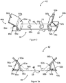
- FIG. 5 shows the blade half-shell 28 with a plurality of web locating devices 42 attached to the inner surface 30 of the half-shell 28, aligned at their respective mounting positions.
- web locating devices 42 shown in Figure 5 are all substantially identical, in other examples and/or in other regions of the blade, web locating devices 42 having a different size or shape may be used.
- each different device 42 may have a different configuration of alignment features 68a, 68b.
- the projected template 74 may therefore have various different reference features 82a, 82b corresponding to the different alignment features 68a, 68b of the different web locating devices 42.
- the correspondence between the alignment features 68a, 68b of the device 42 and the projected reference features 82a, 82b therefore advantageously indicates the correct location for mounting a particular device 42 and thus avoids the possibility of a device 42 being mounted in an incorrect location since it will not be possible to align a device 42 with the reference features 82a, 82b at an incorrect location.
- the projected template 74 therefore not only indicates the correct position of the web locating devices 42 but also the correct orientation of the devices 42.
- first and second guide structures 44a, 44b of the web locating device 42 illustrated in Figure 3 are substantially identical, in other embodiments these may be dissimilar depending for example on the particular profile of the shear webs to be located, and so ensuring the correct orientation of the device 42 may be critical.
- the circular apertures 68a, 68b of the web locating device 42 are configured to allow the device 42 to be accurately aligned with the projected reference features 82a, 82b.
- the thin profile of the base 56 of the device 42 means that the base 56 does not significantly obstruct the projection of the reference features 82a, 82b onto the inner surface 30 of the half-shell 28.
- the chamfered peripheries 70 of the apertures 68a, 68b means that the base 56 has effectively zero thickness at the peripheries 70 of the apertures 68a, 68b. This allows the apertures 68a, 68b to be aligned precisely with the projected reference features 82a, 82b without the base 56 or other parts of the device 42 obscuring the projected light.
- the web locating device 42 spans the shear web mounting region 76 in the chordwise direction C. Specifically, the device 42 is positioned such that the guide structures 44a, 44b are located either side of the shear web mounting region 76, respectively adjacent to the inner and outer edges 78, 80 of the mounting region 76.
- the flexibility of the base 56 of the device 42 advantageously allows the device 42 to conform to the local curvature of the inner surface 30 of the half-shell 28.
- the intermediate connecting portion 46 of the device 42 coincides with and spans the shear web mounting region 76 and defines a seat for the flange of a shear web 34. Since the mutual separation of the guide structures 44a, 44b is fixed by the integrated connecting portion 46, the defined seat is sized to fit the mounting flange 38.
- the device 42 presents a particular advantage over the use of separate unconnected guide blocks arranged adjacent the respective edges 78, 80 of the mounting region 76, where both blocks must be mounted in precisely the right place to ensure a particular separation between the blocks; such arrangements are therefore subject to errors in the alignment of both blocks
- FIG 6a is a cross-sectional view of the web locating device 42 of Figure 5a taken along the line A-A in Figure 5a
- the web locating device 42 is secured to the inner surface 30 of the half-shell 28 by means of pressure sensitive adhesive tape 84 provided on the mounting surface 58 of the base 56.
- the tape 84 is provided on the lower surfaces of the mounting portions 48a, 48b of the guide structures 44a, 44b.
- the pressure sensitive tape 84 is affixed to the inner surface 30 of the half-shell 28 at either side of the shear web 34 mounting region 76.
- the thickness of the tape 84 results in the base 56 of the device 42 being spaced slightly apart from the inner surface 30 of the half shell 28 in the shear web mounting region 76.
- adhesive 86 is applied along the shear web mounting regions 76 indicated by the projected template 74 shown in Figure 5 to define bond lines between the shear webs and the inner surface 30 of the half shell 28.
- the adhesive 86 is applied over the intermediate connecting portion 46 of the web locating device 42.
- the adhesive 86 defines a bond line extending along each shear web mounting region 76, over the intermediate connecting portions 46 of the web locating devices 42.
- the adhesive 86 passes through the apertures 68a, 68b in the intermediate connecting portion 46 of the device 42 and fills the space 88 between the base 56 of the device 42 and the inner surface 30 of the half-shell 28.
- the adhesive 86 also fills the apertures 68a, 68b themselves.
- a shear web 34 is then manoeuvred into position such that the mounting flange 40 occupies the seat defined by the web locating device 42.
- the web locating device 42 is configured to ensure that the shear web 34 is correctly positioned at the shear web mounting region 76.
- the shear web 34 is manoeuvred into position, it is initially guided by the primary guide surfaces 60a, 60b of the web locating device 42 towards the mounting region 76 defined on the inner surface 30 of the half-shell 28.
- the flange 40 of the shear webs 34 is guided by the secondary guide surfaces 62a, 62b of the web locating device 42 in a direction substantially perpendicular to the local surface of the half-shell 28, i.e. the shear web 34 is guided directly onto the shear web mounting region 76. Consequently, the final motion of the shear web 34 towards the mounting region 76 is in a substantially vertical direction and hence substantially no shear force is applied to the shear web 34 at the point that the shear web 34 is positioned at the mounting region 76.
- the absence of shear forces being applied during squeezing of the adhesive 86 ensures that a strong bond is created between the shear webs 34 and the inner surface 30 of the half-shell 28.
- the vertical motion of the shear web 34 also prevents shear forces being applied to the web locating device 42 which advantageously prevents the device being dislodged.
- the edges of the mounting flange 40 abut the secondary guide surfaces 62a, 62b of the web locating device 42 and the shear web mounting flange 40 is correctly positioned at the shear web mounting region 76.
- the specific shape of the web locating devices 42 in other embodiments of the invention may be different.
- devices with a single guide structure 44a or 44b or dissimilar guide structures 44a, 44b are envisaged within the scope of the present invention.
- the alignment features 68a, 68b need not be circular but may be any other suitable shape or size, and may for example comprise cut-outs in the periphery of the base 56. Whilst a laser-projected template 74 is described above, this is not essential to the invention.
- a template may be projected by other means, or a template may be permanently or semi-permanently applied to the inner surfaces of the half shells, for example by marking or printing.
- the adhesive 86 that bonds the shear web 34 to the shell 28 is not applied directly to the shell, but instead is applied to the shear web mounting flange before the shear web is manoeuvred into position onto the shell.
Landscapes
- Engineering & Computer Science (AREA)
- Life Sciences & Earth Sciences (AREA)
- Sustainable Development (AREA)
- Sustainable Energy (AREA)
- Chemical & Material Sciences (AREA)
- Combustion & Propulsion (AREA)
- Mechanical Engineering (AREA)
- General Engineering & Computer Science (AREA)
- Wind Motors (AREA)
Claims (17)
- Dispositif de positionnement de traverse (42) pour positionner une traverse (34) en un emplacement prédéfini sur une surface intérieure (30) d'une paroi de pale d'éolienne (28), le dispositif comprenant :une base (56) pour être fixée à la surface intérieure (30) de la paroi de pale (28) dans une position prédéfinie sur la surface intérieure ; etune première structure de guidage (44a) fait saillie à partir de la base (56), la première structure de guidage ayant une première surface de guidage (60a) agencée pour guider une portion de montage de la traverse vers l'emplacement prédéfini sur la surface intérieure (30) de la paroi de pale d'éolienne (28) ;caractérisé en ce quela base (56) du dispositif inclut un ou plusieurs éléments d'alignement (68a, 68b) pour s'aligner sur un ou plusieurs éléments de référence (82a, 82b) dans la position prédéfinie sur la surface intérieure (30) de la paroi de pale (28).
- Dispositif de positionnement de traverse (42) selon la revendication 1, dans lequel les un ou plusieurs éléments d'alignement (68a, 68b) comprennent une ouverture située dans la base (56).
- Dispositif de positionnement de traverse (42) selon la revendication 2, dans lequel la base (56) rétrécit en épaisseur au niveau d'une périphérie (70) de l'ouverture (68a, 68b).
- Dispositif de positionnement de traverse (42) selon la revendication 2 ou la revendication 3, dans lequel les uns ou plusieurs éléments d'alignement (68a, 68b) comprennent une pluralité d'ouvertures situées dans la base (56).
- Dispositif de positionnement de traverse (42) selon la revendication 4, dans lequel la pluralité d'ouvertures (68a, 68b) comprennent deux ouvertures ayant une forme et/ou une taille différentes l'une de l'autre.
- Dispositif de positionnement de traverse (42) selon l'une quelconque des revendications précédentes, dans lequel la première surface de guidage (44a) est inclinée par rapport à la base (56).
- Dispositif de positionnement de traverse (42) selon l'une quelconque des revendications précédentes, comprenant en outre une seconde structure de guidage (44b) faisant saillie à partir de la base (56), dans lequel les première et seconde structures sont mutuellement espacées par une portion intermédiaire (46) de la base.
- Dispositif de positionnement de traverse (42) selon la revendication 7, dans lequel la seconde structure de guidage (44b) comprend une seconde surface de guidage (60b) agencée pour guider la portion de la traverse vers l'emplacement prédéfini sur la surface intérieure (30) de la paroi de pale d'éolienne (28).
- Dispositif de positionnement de traverse (42) selon la revendication 7 ou la revendication 8, dans lequel les un ou plusieurs éléments d'alignement (68a, 68b) sont situés dans la portion intermédiaire (46) de la base.
- Dispositif de positionnement de traverse (42) selon l'une quelconque des revendications précédentes, dans lequel la base (56) est sensiblement planaire et/ou flexible.
- Dispositif de positionnement de traverse (42) selon l'une quelconque des revendications précédentes, dans lequel le dispositif est formé en tant que pièce moulée unique.
- Dispositif de positionnement de traverse (42) selon l'une quelconque des revendications précédentes, dans lequel la première structure de guidage (44a) fait saillie à partie d'un premier côté de la base (56) et le dispositif comprend en outre une bande adhésive (84) sur un second côté (58) de la base.
- Éolienne (16) comprenant une paroi de pale(28) ayant une surface intérieure (30), dans laquelle un ou plusieurs dispositifs de positionnement de traverse (42) selon l'une quelconque des revendications précédentes sont liés à la surface intérieure.
- Procédé de fabrication d'une pale d'éolienne (16), le procédé comprenant :la fourniture d'une paroi de pale (28) ayant une surface intérieure (30) ;la fourniture d'une traverse (34) ayant une portion de montage pour liaison à la surface intérieure de la paroi de pale ;la fourniture d'un dispositif de positionnement de traverse (42) ayant une base (56) et une ou plusieurs structures de guidage (44a) faisant saillie à partir de la base, la ou chaque structure de guidage ayant une surface de guidage (60a), et la base incluant un ou plusieurs éléments d'alignement (68a, 68b) ;la fourniture d'un ou de plusieurs éléments de référence (82a, 82b) dans une position prédéfinie sur la surface intérieure (30) de la paroi de pale (28) ;l'alignement des un ou plusieurs éléments d'alignement (68a, 68b) de la base (56) du dispositif de positionnement de traverse avec les un ou plusieurs éléments de référence (82a, 82b) ;la fixation de la base (56) du dispositif de positionnement de traverse à la surface intérieure (30) de la paroi de pale dans la position prédéfinie ; etle guidage de la portion de montage de la traverse (34) sur la/les surface(s) de guidage (60a) des une ou plusieurs structures de guidage (44a) vers un emplacement de montage prédéfini défini sur la surface intérieure (30) de la paroi de pale.
- Procédé selon la revendication 14, dans lequel les un ou plusieurs éléments d'alignement (68a, 68b) comprennent une ou plusieurs ouvertures et le procédé comprend l'alignement de la ou de chaque ouverture avec un élément de référence de forme correspondante sur la surface intérieure (30) de la paroi de pale.
- Procédé selon la revendication 15, dans lequel les un ou plusieurs éléments d'alignement (68a, 68b) comprennent au moins deux ouvertures ayant une forme et/ou une taille différentes l'une de l'autre, et le procédé comprend la fourniture d'au moins deux éléments de référence (82a, 82b) dans la position prédéfinie sur la surface intérieure de la paroi de pale, les éléments de référence correspondant chacun en forme et en taille à une ouverture respective.
- Procédé selon la revendication 15 ou la revendication 16, comprenant en outre l'application d'adhésif (86) à l'emplacement prédéfini sur la surface intérieure (30) de la paroi de pale (28) de telle sorte qu'une partie de l'adhésif recouvre au moins partiellement la base (56) du dispositif de positionnement de traverse (42) et passe à travers la ou chaque ouverture (68a, 68b) dans la base pour occuper un espace (88) défini entre la base et la surface intérieure de la paroi de pale dans la position prédéfinie sur la surface intérieure au niveau de laquelle le dispositif est fixé.
Applications Claiming Priority (2)
| Application Number | Priority Date | Filing Date | Title |
|---|---|---|---|
| DKPA201570764 | 2015-11-26 | ||
| PCT/DK2016/050393 WO2017088890A1 (fr) | 2015-11-26 | 2016-11-23 | Améliorations concernant la fabrication de pales de turbine éolienne |
Publications (2)
| Publication Number | Publication Date |
|---|---|
| EP3380721A1 EP3380721A1 (fr) | 2018-10-03 |
| EP3380721B1 true EP3380721B1 (fr) | 2020-01-08 |
Family
ID=58763197
Family Applications (1)
| Application Number | Title | Priority Date | Filing Date |
|---|---|---|---|
| EP16805278.5A Active EP3380721B1 (fr) | 2015-11-26 | 2016-11-23 | Améliorations concernant la fabrication de pales de turbine éolienne |
Country Status (5)
| Country | Link |
|---|---|
| US (1) | US10920744B2 (fr) |
| EP (1) | EP3380721B1 (fr) |
| CN (1) | CN108495999B (fr) |
| DK (1) | DK3380721T3 (fr) |
| WO (1) | WO2017088890A1 (fr) |
Families Citing this family (8)
| Publication number | Priority date | Publication date | Assignee | Title |
|---|---|---|---|---|
| GB2529186A (en) * | 2014-08-12 | 2016-02-17 | Vestas Wind Sys As | Improvements relating to wind turbine blade manufacture |
| CN110944829B (zh) * | 2017-06-06 | 2021-12-21 | 维斯塔斯风力系统有限公司 | 风轮机叶片制造方面的改进 |
| ES2949401T3 (es) | 2017-11-07 | 2023-09-28 | Vestas Wind Sys As | Mejoras relativas a la fabricación de palas de aerogeneradores |
| DK3707372T3 (da) * | 2017-11-10 | 2022-06-13 | Vestas Wind Sys As | Forbedringer i forbindelse med vindmøllevingefremstilling |
| US20220009182A1 (en) | 2018-11-13 | 2022-01-13 | Lm Wind Power A/S | A detection system, a method and a detection device thereof |
| WO2020114564A1 (fr) * | 2018-12-03 | 2020-06-11 | Vestas Wind Systems A/S | Améliorations apportées à la fabrication dune pale d'éolienne |
| EP4039453A1 (fr) * | 2021-02-04 | 2022-08-10 | LM Wind Power A/S | Élément de guidage pour guider une bande de cisaillement d'une pale d'éolienne |
| CN113217270B (zh) * | 2021-05-31 | 2022-12-02 | 中材科技风电叶片股份有限公司 | 定位工装、腹板组装方法、叶片及风电机组 |
Family Cites Families (30)
| Publication number | Priority date | Publication date | Assignee | Title |
|---|---|---|---|---|
| US400803A (en) * | 1889-04-02 | Hiram c | ||
| US1180648A (en) * | 1915-03-15 | 1916-04-25 | Hubbell Inc Harvey | Attachment-plug. |
| US3663931A (en) * | 1970-11-25 | 1972-05-16 | Collins Radio Co | Pin and socket contact electrical interconnect system |
| US4671470A (en) * | 1985-07-15 | 1987-06-09 | Beech Aircraft Corporation | Method for fastening aircraft frame elements to sandwich skin panels covering same using woven fiber connectors |
| US7244487B2 (en) * | 2003-04-24 | 2007-07-17 | Lockheed Martin Corporation | Apparatus, system, and method of joining structural components with a tapered tension bond joint |
| US7670527B2 (en) * | 2006-05-09 | 2010-03-02 | Lockheed Martin Corporation | Failsafe injected adhesive joint |
| US7810757B2 (en) * | 2006-11-02 | 2010-10-12 | The Boeing Company | Mounting device for an aircraft |
| WO2008089765A2 (fr) | 2007-01-25 | 2008-07-31 | Danmarks Tekniske Universitet | Pale d'éolienne renforcée |
| ES2684123T3 (es) * | 2007-02-27 | 2018-10-01 | Vestas Wind Systems A/S | Una pala de turbina eólica y método para el ensamblaje de una pala de turbina eólica |
| US8167569B2 (en) * | 2007-12-21 | 2012-05-01 | General Electric Company | Structure and method for self-aligning rotor blade joints |
| US20100143142A1 (en) * | 2008-12-11 | 2010-06-10 | Afroz Akhtar | Sparcap system for wind turbine rotor blade and method of fabricating wind turbine rotor blade |
| US7841835B2 (en) * | 2009-02-20 | 2010-11-30 | General Electric Company | Spar cap for wind turbine blades |
| CN101830074A (zh) | 2009-03-09 | 2010-09-15 | 汉德风电设备(阜宁)有限公司 | 风电叶片制作工艺 |
| DE102009031947A1 (de) * | 2009-07-07 | 2011-01-13 | Nordex Energy Gmbh | Rotorblatt für eine Windenergieanlage und Verfahren zu dessen Herstellung |
| DE102010003114A1 (de) * | 2010-03-22 | 2011-09-22 | Repower Systems Ag | Stegverbindung |
| US8317483B2 (en) | 2010-12-15 | 2012-11-27 | General Electric Company | Wind turbine rotor blade |
| WO2012091695A1 (fr) * | 2010-12-28 | 2012-07-05 | Bell Helicopter Textron Inc. | Système d'assemblage à charge multidirectionnelle |
| CN102554817B (zh) * | 2010-12-31 | 2015-07-15 | 上海艾郎风电科技发展有限公司 | 腹板定位装置及叶片腹板成型方法 |
| ES2398553B1 (es) | 2011-02-24 | 2014-02-06 | Gamesa Innovation & Technology S.L. | Una pala de aerogenerador multi-panel mejorada. |
| US8262362B2 (en) | 2011-06-08 | 2012-09-11 | General Electric Company | Wind turbine blade shear web with spring flanges |
| US8235671B2 (en) | 2011-07-19 | 2012-08-07 | General Electric Company | Wind turbine blade shear web connection assembly |
| US8393871B2 (en) * | 2011-07-19 | 2013-03-12 | General Electric Company | Wind turbine blade shear web connection assembly |
| US9458823B2 (en) * | 2011-12-12 | 2016-10-04 | General Electric Company | Wind turbine blade shear web connection assembly |
| US8956115B2 (en) * | 2012-01-20 | 2015-02-17 | General Electric Company | Blade extension and rotor blade assembly for wind turbine |
| DE102012204858A1 (de) | 2012-03-27 | 2013-10-02 | Repower Systems Se | Fertigung eines Faserverbundbauteils für ein Rotorblatt |
| CN104995400B (zh) | 2012-12-20 | 2018-03-20 | 维斯塔斯风力系统有限公司 | 风轮机叶片抗剪腹板的对准 |
| WO2015003717A1 (fr) | 2013-07-11 | 2015-01-15 | Vestas Wind Systems A/S | Pales d'éolienne |
| US20150152838A1 (en) * | 2013-12-02 | 2015-06-04 | General Electric Company | Spar caps-shear web assembly configuration for wind turbine blades, and methods thereof |
| US9745954B2 (en) * | 2014-04-30 | 2017-08-29 | General Electric Company | Rotor blade joint assembly with multi-component shear web |
| GB2527587A (en) | 2014-06-27 | 2015-12-30 | Vestas Wind Sys As | Improvements relating to wind turbine blade manufacture |
-
2016
- 2016-11-23 WO PCT/DK2016/050393 patent/WO2017088890A1/fr active Application Filing
- 2016-11-23 DK DK16805278.5T patent/DK3380721T3/da active
- 2016-11-23 CN CN201680079830.5A patent/CN108495999B/zh active Active
- 2016-11-23 US US15/777,398 patent/US10920744B2/en active Active
- 2016-11-23 EP EP16805278.5A patent/EP3380721B1/fr active Active
Non-Patent Citations (1)
| Title |
|---|
| None * |
Also Published As
| Publication number | Publication date |
|---|---|
| CN108495999A (zh) | 2018-09-04 |
| CN108495999B (zh) | 2020-08-07 |
| EP3380721A1 (fr) | 2018-10-03 |
| WO2017088890A1 (fr) | 2017-06-01 |
| US20180328335A1 (en) | 2018-11-15 |
| US10920744B2 (en) | 2021-02-16 |
| DK3380721T3 (da) | 2020-02-17 |
Similar Documents
| Publication | Publication Date | Title |
|---|---|---|
| EP3380721B1 (fr) | Améliorations concernant la fabrication de pales de turbine éolienne | |
| EP2935875B1 (fr) | Méthode d'alignement de bandes de cisaillement d'aube de turbine | |
| US11408393B2 (en) | Protective shield with positioning mark | |
| US11761421B2 (en) | Wind turbine blade manufacture | |
| EP3475068B1 (fr) | Fabrication d'une pale d'éolienne | |
| US9624782B2 (en) | Template for aligning surface features on a rotor blade | |
| ES2366460T3 (es) | Álabe de turbina eólica. | |
| EP2453129B1 (fr) | Pale d'éolienne | |
| US10632689B2 (en) | Wind turbine blade manufacture | |
| EP2570254A1 (fr) | Procédé de fabrication d'une pale de rotor d'éolienne avec âme de cisaillement | |
| JP7378884B2 (ja) | 風力タービンブレードの製作中の部品位置特定のための金型精密ピン | |
| CN105980700A (zh) | 用于风力涡轮机叶片的隔板组件 | |
| GB2488099A (en) | Modular wind turbine blade with both spar and foil sections forming aerodynamic profile | |
| EP3706987B1 (fr) | Améliorations apportées à la fabrication de pale d'éolienne | |
| EP2481914A1 (fr) | Pale de rotor d'éolienne et procédé de fabrication pour celle-ci | |
| US20220402171A1 (en) | A clamping tong and a mould system comprising the same | |
| CN104948392B (zh) | 用于风力涡轮机的转子叶片 | |
| WO2023237170A1 (fr) | Procédé de fabrication d'un composant de pale d'éolienne |
Legal Events
| Date | Code | Title | Description |
|---|---|---|---|
| STAA | Information on the status of an ep patent application or granted ep patent |
Free format text: STATUS: UNKNOWN |
|
| STAA | Information on the status of an ep patent application or granted ep patent |
Free format text: STATUS: THE INTERNATIONAL PUBLICATION HAS BEEN MADE |
|
| PUAI | Public reference made under article 153(3) epc to a published international application that has entered the european phase |
Free format text: ORIGINAL CODE: 0009012 |
|
| STAA | Information on the status of an ep patent application or granted ep patent |
Free format text: STATUS: REQUEST FOR EXAMINATION WAS MADE |
|
| 17P | Request for examination filed |
Effective date: 20180607 |
|
| AK | Designated contracting states |
Kind code of ref document: A1 Designated state(s): AL AT BE BG CH CY CZ DE DK EE ES FI FR GB GR HR HU IE IS IT LI LT LU LV MC MK MT NL NO PL PT RO RS SE SI SK SM TR |
|
| AX | Request for extension of the european patent |
Extension state: BA ME |
|
| DAV | Request for validation of the european patent (deleted) | ||
| DAX | Request for extension of the european patent (deleted) | ||
| GRAP | Despatch of communication of intention to grant a patent |
Free format text: ORIGINAL CODE: EPIDOSNIGR1 |
|
| STAA | Information on the status of an ep patent application or granted ep patent |
Free format text: STATUS: GRANT OF PATENT IS INTENDED |
|
| INTG | Intention to grant announced |
Effective date: 20190717 |
|
| GRAS | Grant fee paid |
Free format text: ORIGINAL CODE: EPIDOSNIGR3 |
|
| GRAA | (expected) grant |
Free format text: ORIGINAL CODE: 0009210 |
|
| STAA | Information on the status of an ep patent application or granted ep patent |
Free format text: STATUS: THE PATENT HAS BEEN GRANTED |
|
| AK | Designated contracting states |
Kind code of ref document: B1 Designated state(s): AL AT BE BG CH CY CZ DE DK EE ES FI FR GB GR HR HU IE IS IT LI LT LU LV MC MK MT NL NO PL PT RO RS SE SI SK SM TR |
|
| REG | Reference to a national code |
Ref country code: GB Ref legal event code: FG4D |
|
| REG | Reference to a national code |
Ref country code: CH Ref legal event code: EP |
|
| REG | Reference to a national code |
Ref country code: DE Ref legal event code: R096 Ref document number: 602016028013 Country of ref document: DE |
|
| REG | Reference to a national code |
Ref country code: IE Ref legal event code: FG4D |
|
| REG | Reference to a national code |
Ref country code: AT Ref legal event code: REF Ref document number: 1223042 Country of ref document: AT Kind code of ref document: T Effective date: 20200215 |
|
| REG | Reference to a national code |
Ref country code: DK Ref legal event code: T3 Effective date: 20200211 |
|
| REG | Reference to a national code |
Ref country code: NL Ref legal event code: MP Effective date: 20200108 |
|
| REG | Reference to a national code |
Ref country code: LT Ref legal event code: MG4D |
|
| PG25 | Lapsed in a contracting state [announced via postgrant information from national office to epo] |
Ref country code: NL Free format text: LAPSE BECAUSE OF FAILURE TO SUBMIT A TRANSLATION OF THE DESCRIPTION OR TO PAY THE FEE WITHIN THE PRESCRIBED TIME-LIMIT Effective date: 20200108 Ref country code: LT Free format text: LAPSE BECAUSE OF FAILURE TO SUBMIT A TRANSLATION OF THE DESCRIPTION OR TO PAY THE FEE WITHIN THE PRESCRIBED TIME-LIMIT Effective date: 20200108 Ref country code: FI Free format text: LAPSE BECAUSE OF FAILURE TO SUBMIT A TRANSLATION OF THE DESCRIPTION OR TO PAY THE FEE WITHIN THE PRESCRIBED TIME-LIMIT Effective date: 20200108 Ref country code: NO Free format text: LAPSE BECAUSE OF FAILURE TO SUBMIT A TRANSLATION OF THE DESCRIPTION OR TO PAY THE FEE WITHIN THE PRESCRIBED TIME-LIMIT Effective date: 20200408 Ref country code: PT Free format text: LAPSE BECAUSE OF FAILURE TO SUBMIT A TRANSLATION OF THE DESCRIPTION OR TO PAY THE FEE WITHIN THE PRESCRIBED TIME-LIMIT Effective date: 20200531 Ref country code: RS Free format text: LAPSE BECAUSE OF FAILURE TO SUBMIT A TRANSLATION OF THE DESCRIPTION OR TO PAY THE FEE WITHIN THE PRESCRIBED TIME-LIMIT Effective date: 20200108 |
|
| PG25 | Lapsed in a contracting state [announced via postgrant information from national office to epo] |
Ref country code: IS Free format text: LAPSE BECAUSE OF FAILURE TO SUBMIT A TRANSLATION OF THE DESCRIPTION OR TO PAY THE FEE WITHIN THE PRESCRIBED TIME-LIMIT Effective date: 20200508 Ref country code: HR Free format text: LAPSE BECAUSE OF FAILURE TO SUBMIT A TRANSLATION OF THE DESCRIPTION OR TO PAY THE FEE WITHIN THE PRESCRIBED TIME-LIMIT Effective date: 20200108 Ref country code: GR Free format text: LAPSE BECAUSE OF FAILURE TO SUBMIT A TRANSLATION OF THE DESCRIPTION OR TO PAY THE FEE WITHIN THE PRESCRIBED TIME-LIMIT Effective date: 20200409 Ref country code: SE Free format text: LAPSE BECAUSE OF FAILURE TO SUBMIT A TRANSLATION OF THE DESCRIPTION OR TO PAY THE FEE WITHIN THE PRESCRIBED TIME-LIMIT Effective date: 20200108 Ref country code: LV Free format text: LAPSE BECAUSE OF FAILURE TO SUBMIT A TRANSLATION OF THE DESCRIPTION OR TO PAY THE FEE WITHIN THE PRESCRIBED TIME-LIMIT Effective date: 20200108 Ref country code: BG Free format text: LAPSE BECAUSE OF FAILURE TO SUBMIT A TRANSLATION OF THE DESCRIPTION OR TO PAY THE FEE WITHIN THE PRESCRIBED TIME-LIMIT Effective date: 20200408 |
|
| REG | Reference to a national code |
Ref country code: DE Ref legal event code: R097 Ref document number: 602016028013 Country of ref document: DE |
|
| PG25 | Lapsed in a contracting state [announced via postgrant information from national office to epo] |
Ref country code: EE Free format text: LAPSE BECAUSE OF FAILURE TO SUBMIT A TRANSLATION OF THE DESCRIPTION OR TO PAY THE FEE WITHIN THE PRESCRIBED TIME-LIMIT Effective date: 20200108 Ref country code: SM Free format text: LAPSE BECAUSE OF FAILURE TO SUBMIT A TRANSLATION OF THE DESCRIPTION OR TO PAY THE FEE WITHIN THE PRESCRIBED TIME-LIMIT Effective date: 20200108 Ref country code: ES Free format text: LAPSE BECAUSE OF FAILURE TO SUBMIT A TRANSLATION OF THE DESCRIPTION OR TO PAY THE FEE WITHIN THE PRESCRIBED TIME-LIMIT Effective date: 20200108 Ref country code: CZ Free format text: LAPSE BECAUSE OF FAILURE TO SUBMIT A TRANSLATION OF THE DESCRIPTION OR TO PAY THE FEE WITHIN THE PRESCRIBED TIME-LIMIT Effective date: 20200108 Ref country code: RO Free format text: LAPSE BECAUSE OF FAILURE TO SUBMIT A TRANSLATION OF THE DESCRIPTION OR TO PAY THE FEE WITHIN THE PRESCRIBED TIME-LIMIT Effective date: 20200108 Ref country code: SK Free format text: LAPSE BECAUSE OF FAILURE TO SUBMIT A TRANSLATION OF THE DESCRIPTION OR TO PAY THE FEE WITHIN THE PRESCRIBED TIME-LIMIT Effective date: 20200108 |
|
| PLBE | No opposition filed within time limit |
Free format text: ORIGINAL CODE: 0009261 |
|
| STAA | Information on the status of an ep patent application or granted ep patent |
Free format text: STATUS: NO OPPOSITION FILED WITHIN TIME LIMIT |
|
| REG | Reference to a national code |
Ref country code: AT Ref legal event code: MK05 Ref document number: 1223042 Country of ref document: AT Kind code of ref document: T Effective date: 20200108 |
|
| 26N | No opposition filed |
Effective date: 20201009 |
|
| PG25 | Lapsed in a contracting state [announced via postgrant information from national office to epo] |
Ref country code: IT Free format text: LAPSE BECAUSE OF FAILURE TO SUBMIT A TRANSLATION OF THE DESCRIPTION OR TO PAY THE FEE WITHIN THE PRESCRIBED TIME-LIMIT Effective date: 20200108 Ref country code: AT Free format text: LAPSE BECAUSE OF FAILURE TO SUBMIT A TRANSLATION OF THE DESCRIPTION OR TO PAY THE FEE WITHIN THE PRESCRIBED TIME-LIMIT Effective date: 20200108 |
|
| PG25 | Lapsed in a contracting state [announced via postgrant information from national office to epo] |
Ref country code: PL Free format text: LAPSE BECAUSE OF FAILURE TO SUBMIT A TRANSLATION OF THE DESCRIPTION OR TO PAY THE FEE WITHIN THE PRESCRIBED TIME-LIMIT Effective date: 20200108 Ref country code: SI Free format text: LAPSE BECAUSE OF FAILURE TO SUBMIT A TRANSLATION OF THE DESCRIPTION OR TO PAY THE FEE WITHIN THE PRESCRIBED TIME-LIMIT Effective date: 20200108 |
|
| PG25 | Lapsed in a contracting state [announced via postgrant information from national office to epo] |
Ref country code: MC Free format text: LAPSE BECAUSE OF FAILURE TO SUBMIT A TRANSLATION OF THE DESCRIPTION OR TO PAY THE FEE WITHIN THE PRESCRIBED TIME-LIMIT Effective date: 20200108 |
|
| REG | Reference to a national code |
Ref country code: CH Ref legal event code: PL |
|
| PG25 | Lapsed in a contracting state [announced via postgrant information from national office to epo] |
Ref country code: LU Free format text: LAPSE BECAUSE OF NON-PAYMENT OF DUE FEES Effective date: 20201123 |
|
| REG | Reference to a national code |
Ref country code: BE Ref legal event code: MM Effective date: 20201130 |
|
| PG25 | Lapsed in a contracting state [announced via postgrant information from national office to epo] |
Ref country code: CH Free format text: LAPSE BECAUSE OF NON-PAYMENT OF DUE FEES Effective date: 20201130 Ref country code: LI Free format text: LAPSE BECAUSE OF NON-PAYMENT OF DUE FEES Effective date: 20201130 |
|
| PG25 | Lapsed in a contracting state [announced via postgrant information from national office to epo] |
Ref country code: IE Free format text: LAPSE BECAUSE OF NON-PAYMENT OF DUE FEES Effective date: 20201123 |
|
| PG25 | Lapsed in a contracting state [announced via postgrant information from national office to epo] |
Ref country code: TR Free format text: LAPSE BECAUSE OF FAILURE TO SUBMIT A TRANSLATION OF THE DESCRIPTION OR TO PAY THE FEE WITHIN THE PRESCRIBED TIME-LIMIT Effective date: 20200108 Ref country code: MT Free format text: LAPSE BECAUSE OF FAILURE TO SUBMIT A TRANSLATION OF THE DESCRIPTION OR TO PAY THE FEE WITHIN THE PRESCRIBED TIME-LIMIT Effective date: 20200108 Ref country code: CY Free format text: LAPSE BECAUSE OF FAILURE TO SUBMIT A TRANSLATION OF THE DESCRIPTION OR TO PAY THE FEE WITHIN THE PRESCRIBED TIME-LIMIT Effective date: 20200108 |
|
| PG25 | Lapsed in a contracting state [announced via postgrant information from national office to epo] |
Ref country code: MK Free format text: LAPSE BECAUSE OF FAILURE TO SUBMIT A TRANSLATION OF THE DESCRIPTION OR TO PAY THE FEE WITHIN THE PRESCRIBED TIME-LIMIT Effective date: 20200108 Ref country code: AL Free format text: LAPSE BECAUSE OF FAILURE TO SUBMIT A TRANSLATION OF THE DESCRIPTION OR TO PAY THE FEE WITHIN THE PRESCRIBED TIME-LIMIT Effective date: 20200108 |
|
| PG25 | Lapsed in a contracting state [announced via postgrant information from national office to epo] |
Ref country code: BE Free format text: LAPSE BECAUSE OF NON-PAYMENT OF DUE FEES Effective date: 20201130 |
|
| P01 | Opt-out of the competence of the unified patent court (upc) registered |
Effective date: 20230521 |
|
| PGFP | Annual fee paid to national office [announced via postgrant information from national office to epo] |
Ref country code: GB Payment date: 20231121 Year of fee payment: 8 |
|
| PGFP | Annual fee paid to national office [announced via postgrant information from national office to epo] |
Ref country code: FR Payment date: 20231123 Year of fee payment: 8 Ref country code: DK Payment date: 20231123 Year of fee payment: 8 Ref country code: DE Payment date: 20231127 Year of fee payment: 8 |