EP3380376B1 - Verfahren und vorrichtung zum betreiben eines bremssystems für ein fahrzeug und bremssystem - Google Patents
Verfahren und vorrichtung zum betreiben eines bremssystems für ein fahrzeug und bremssystem Download PDFInfo
- Publication number
- EP3380376B1 EP3380376B1 EP16805350.2A EP16805350A EP3380376B1 EP 3380376 B1 EP3380376 B1 EP 3380376B1 EP 16805350 A EP16805350 A EP 16805350A EP 3380376 B1 EP3380376 B1 EP 3380376B1
- Authority
- EP
- European Patent Office
- Prior art keywords
- signal
- brake mechanism
- service brake
- parking brake
- vehicle
- Prior art date
- Legal status (The legal status is an assumption and is not a legal conclusion. Google has not performed a legal analysis and makes no representation as to the accuracy of the status listed.)
- Revoked
Links
- 238000000034 method Methods 0.000 title claims description 21
- 238000013459 approach Methods 0.000 description 7
- 230000007547 defect Effects 0.000 description 6
- 238000004891 communication Methods 0.000 description 4
- 230000008901 benefit Effects 0.000 description 2
- 238000013461 design Methods 0.000 description 2
- 238000010586 diagram Methods 0.000 description 2
- 230000007257 malfunction Effects 0.000 description 2
- 230000004044 response Effects 0.000 description 2
- 230000004913 activation Effects 0.000 description 1
- 230000002950 deficient Effects 0.000 description 1
- 230000001419 dependent effect Effects 0.000 description 1
- 238000011161 development Methods 0.000 description 1
- 230000018109 developmental process Effects 0.000 description 1
- 230000005611 electricity Effects 0.000 description 1
- 230000002349 favourable effect Effects 0.000 description 1
- 230000010354 integration Effects 0.000 description 1
- 239000000203 mixture Substances 0.000 description 1
- 238000012806 monitoring device Methods 0.000 description 1
- 230000008569 process Effects 0.000 description 1
- 230000004083 survival effect Effects 0.000 description 1
Images

Classifications
-
- B—PERFORMING OPERATIONS; TRANSPORTING
- B60—VEHICLES IN GENERAL
- B60T—VEHICLE BRAKE CONTROL SYSTEMS OR PARTS THEREOF; BRAKE CONTROL SYSTEMS OR PARTS THEREOF, IN GENERAL; ARRANGEMENT OF BRAKING ELEMENTS ON VEHICLES IN GENERAL; PORTABLE DEVICES FOR PREVENTING UNWANTED MOVEMENT OF VEHICLES; VEHICLE MODIFICATIONS TO FACILITATE COOLING OF BRAKES
- B60T13/00—Transmitting braking action from initiating means to ultimate brake actuator with power assistance or drive; Brake systems incorporating such transmitting means, e.g. air-pressure brake systems
- B60T13/10—Transmitting braking action from initiating means to ultimate brake actuator with power assistance or drive; Brake systems incorporating such transmitting means, e.g. air-pressure brake systems with fluid assistance, drive, or release
- B60T13/66—Electrical control in fluid-pressure brake systems
- B60T13/662—Electrical control in fluid-pressure brake systems characterised by specified functions of the control system components
-
- B—PERFORMING OPERATIONS; TRANSPORTING
- B60—VEHICLES IN GENERAL
- B60T—VEHICLE BRAKE CONTROL SYSTEMS OR PARTS THEREOF; BRAKE CONTROL SYSTEMS OR PARTS THEREOF, IN GENERAL; ARRANGEMENT OF BRAKING ELEMENTS ON VEHICLES IN GENERAL; PORTABLE DEVICES FOR PREVENTING UNWANTED MOVEMENT OF VEHICLES; VEHICLE MODIFICATIONS TO FACILITATE COOLING OF BRAKES
- B60T17/00—Component parts, details, or accessories of power brake systems not covered by groups B60T8/00, B60T13/00 or B60T15/00, or presenting other characteristic features
- B60T17/18—Safety devices; Monitoring
- B60T17/22—Devices for monitoring or checking brake systems; Signal devices
Definitions
- the invention is based on a device or a method according to the type of the independent claims.
- pneumatic valves for brake cylinders of the individual axles or wheels of the commercial vehicle are controlled by electrical signals.
- the electronic brake system has a redundant option for actuating the brake cylinders.
- the pneumatic valves can then be operated directly via compressed air signals to bring the commercial vehicle to a stop.
- a complete reserve braking system is available to brake the commercial vehicle once to a standstill in the event of a fault.
- WO 2015/036393 A1 discloses a method for operating a motor vehicle having a service brake and a parking brake. If a fault in the service brake system is identified, the parking brake takes over the deceleration requests.
- JP 2008 1 26962 A discloses a parking brake control device for a motor vehicle. If the service brake is out of operation, the parking brake can be used for braking.
- a parking brake or parking brake which is also built into the commercial vehicle, can be used to brake the commercial vehicle.
- the components of the braking system can be simplified and resources and costs saved.
- an electropneumatic parking brake or electropneumatic parking brake can be used to bring the commercial vehicle to a stop.
- a vehicle can be understood as a commercial vehicle, in particular a bus, a truck or a tractor.
- a service brake device can be an electronic brake system of the vehicle. The vehicle can have a trailer or semi-trailer braked by the service brake system.
- a parking brake device can be an electro-pneumatic parking brake of the vehicle.
- a delay signal can be an electrical signal. The delay signal can be designed to transmit data or values representing the delay request.
- a deceleration request can be a target value for braking power on the vehicle. The delay request can be provided by an assistance system of the vehicle. The deceleration request can also be recorded via a brake pedal of the vehicle.
- a function signal can be an electrical signal. The function signal can be read in by a monitoring device of the service brake device.
- the function signal can be based on data provided by a sensor device.
- a malfunction can, for example, be caused by a defect.
- On Actuation signal can be an electrical signal.
- the actuation signal can be designed to transmit data or values representing the delay request. The actuation signal can thus represent the delay request.
- the actuation signal can be provided for a rear axle parking brake device of the parking brake device for braking a rear axle of the vehicle if the function signal signals a restricted functionality of a rear axle service brake device of the service brake device on the rear axle.
- the actuation signal can be provided for a front axle parking brake device of the parking brake device for braking a front axle of the vehicle if the function signal signals a restricted functionality of a front axle service brake device of the service brake device on the front axle.
- the actuation signal can be provided for a trailer parking brake device of the parking brake device for braking a trailer of the vehicle if the function signal signals a restricted functionality of a trailer service brake device of the service brake device of the trailer.
- Braking devices can be electro-pneumatic valves. The braking devices for the front axle, the rear axle and the trailer can either be controlled jointly and / or selectively. This enables the service brake device to be metered, since it is possible to switch to the parking brake device where there is a defect.
- a service brake signal can be provided for the service brake device using the delay signal if the function signal signals the intended functionality of the service brake device.
- the deceleration request can then be directed to the service brake device if it functions as intended.
- the function signal can be read in via an interface to a control unit of the service brake device.
- the actuation signal can be via a Interface to a control unit of the parking brake device can be provided.
- a modular system can be created via interfaces. The functionality of the described method can thus be implemented in an independent unit. Alternatively, the corresponding functionality can also be integrated into an already existing control unit, for example the control unit of the service brake device or the control unit of the parking brake device.
- a parking brake signal can be provided for the parking brake device if the deceleration signal signals a parking brake request. This means that the vehicle can be locked when it is stationary so that it does not roll. A separate activation of the parking brake device can be omitted.
- the delay signal will be read in via an interface to a foot brake module of the service brake device.
- a modular system can be created via interfaces.
- the method further comprises a step of detecting the deceleration signal using the foot brake module.
- a device which is designed to carry out, control or implement the steps of a variant of a method presented here in corresponding devices.
- This embodiment variant of the invention in the form of a device can also be used to achieve the object on which the invention is based quickly and efficiently.
- a device can be understood to mean an electrical device which is designed to process sensor signals and to output control and / or data signals as a function thereof.
- the device can have a hardware and / or software interface.
- a brake system for a vehicle with a service brake device and a parking brake device is presented, the service brake device and the parking brake device being connected via interfaces to a device for operating the vehicle according to the approach presented here.
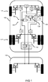
- Fig. 1 shows a representation of a commercial vehicle 100 with a brake system 102 according to an embodiment.
- the commercial vehicle 100 is a truck 100 here.
- the commercial vehicle 100 pulls a trailer 104.
- the commercial vehicle 100 can also be a tractor. Then the tractor can be coupled to a trailer. Wheels of the commercial vehicle 100 are braked by air brakes.
- the commercial vehicle 100 here has pneumatic disc brakes on all wheels.
- the commercial vehicle 100 can also have drum brakes.
- the commercial vehicle 100 can have a mixture of disc brakes and drum brakes.
- the brake system 102 comprises a service brake device 106, a parking brake device 108 and a device 110 for operating the brake system 102 for the commercial vehicle 100.
- the device 110 is connected to a control unit 112 of the service brake device 106 and a control unit 114 of the parking brake device 108.
- the device 110 is designed as an independent unit that is connected to the control devices 112, 114 via interfaces. This has the advantage that the device 110 still, for example, in the event of a complete failure of the control device 112 of the service brake device 106 is ready for use.
- the device 110 is integrated in one of the control devices 112, 114. Through such an integration, the functionality of the device 110 can be inexpensively integrated into a known system.
- the service brake device 106 comprises two devices 116 for actuating the brakes on the front axle 118, a device 120 for actuating the brakes on the rear axle 122 and a device 124 for actuating the brakes of the trailer 104.
- the devices 116 for actuating the brakes on the front axle 118 can be referred to as front axle service braking devices 116.
- the device 120 for actuating the brakes on the rear axle 122 can be referred to as the rear axle service brake device 120.
- the device 124 for actuating the brakes of the trailer 104 can be used as
- Trailer service brake device 124 are referred to.
- the devices 116, 120, 124 are electronically controllable pneumatic valves, wherein a compressed air supply for the valves 116, 120, 124 is not shown here.
- Controller 112 in response to a delay signal 126, sends electrical control signals to valves 116, 120, 124 via control lines to open or close them.
- the delay signal 126 represents a desired delay for the commercial vehicle 100 or the team.
- the delay signal 126 is read in, for example, using a foot brake module of the commercial vehicle 100.
- the delay signal 126 can also be provided by a driver assistance system of the commercial vehicle 100, for example in order to maintain a safety distance from a vehicle in front by braking the team.
- the control device 112 is designed to query a status of the devices 116, 120, 124 via the control lines. Furthermore, the control device 112 is designed to evaluate the status of the devices 116, 120, 124 and to generate a function signal 128.
- the function signal 128 represents a functionality of the service brake device 106. The function signal 128 is sent to the device 110.
- the parking brake device 108 includes a device 130 for actuating the brakes on the front axle 118, a device 132 for actuating the brakes on the rear axle 122 and a device 134 for actuating the brakes of the trailer 104.
- the device 130 for actuating the brakes on the front axle 118 can be referred to as a front axle parking brake device 130.
- the device 132 for actuating the brakes on the rear axle 122 can be referred to as a rear axle parking brake device 132.
- the device 134 for actuating the brakes of the trailer 104 can be referred to as a trailer parking brake device 134.
- the devices 130, 132, 134 can also be valves that can be controlled electronically and / or controlled purely pneumatically.
- the compressed air supply to the valves 130, 132, 134 is not shown here.
- the control unit 114 in response to a parking brake signal 136, the control unit 114 sends electrical control signals to the valves 130, 132, 134 via control lines in order to open or close them.
- the parking brake signal 136 represents a desired actuation of the parking brake device 108.
- the devices 114 and 132 can be combined to form a parking brake device, which brakes only the rear axle of the train vehicle and, together with the trailer control module 140 and the device 134 contained therein, also brakes the trailer.
- the front axle can also be included again.
- the device 110 is designed to read in the delay signal 126 and to evaluate the function signal 128. Using the delay signal 126 and the function signal 128, the device 110 provides an actuation signal 138 for the parking brake device 108 when the function signal 128 signals an at least restricted functionality or a fault in the service brake device 106 and the delay signal 126 signals a delay request. In the brake system 102 presented here, the parking brake device 108 is thus redundant to the service brake device 106.
- the delay signal 126 can also only be read in by the device 110.
- the device 110 can then provide a service brake signal for the service brake device if the function signal 128 signals the functionality of the service brake device.
- the device 110 thus acts as a switch for the delay signal 126.
- the devices 130, 132, 134 on the front axle 118, the rear axle 122 and / or the trailer 104 are selectively actuated when the function signal 128 signals a defect on the front axle 118, the rear axle 192 and / or the trailer 104.
- the functionalities of the devices 124, 134 are combined in a device designated as a trailer control module 140.
- the devices 124, 134 are designed as separate modules or devices.
- the trailer 104 has its own braking system which can be controlled by the devices 124, 134.
- a use of the electropneumatic parking / parking brake (EPB) 108 of a commercial vehicle 100 as a back-up for the electronic braking system (EBS) 106 of the commercial vehicle 100 is described.
- EBS electronic braking system
- the pneumatic back-up in the electronic brake system (EBS) 106 which was typically previously present in a commercial vehicle 100, can be omitted and replaced by the electro-pneumatic parking brake (EPB) 108.
- the brake system 102 described here can be made less complex and safer.
- ABS Anti-lock braking system
- ASR anti-slip control
- DTC dynamic train control
- ESP electronic stability program
- AEBS advanced emergency braking system
- an electropneumatic parking brake 108 or parking brake (EPB) 108 as an independent electronic system, the electro-pneumatic parking brake 108 can take over the back-up function for the electronic brake system 106 in the approach presented here, and the pneumatic back-up can be dispensed with in the electronic brake system , which can lead to a considerable cost advantage for future electronic braking systems.
- the foot brake module Due to the approach presented here, the foot brake module (FBM) requires no or only a pneumatic back-up. In the best case, the foot brake module consists only of a purely electronic part. A mechanical part can be provided for the pedal feel.
- EPM electropneumatic modules
- TCM trailer control modules
- the foot brake module has electronics that communicate with the control device 112 of the electronic brake system 106 via a digital interface and can also be supplied electrically by the latter.
- the electronics can be supplied with electricity by the control unit 114 of the electropneumatic parking brake 108, for example when the control unit 112 of the electronic brake system 106 is switched off due to a fault.
- the control unit 114 of the electro-pneumatic parking brake 108 can take over the communication via the existing interface or a redundant second digital interface.
- both control devices 112, 114 can communicate with the digital foot brake module, wherein the control device 114 of the electropneumatic parking brake 108 only communicates with the digital foot brake module when the control device 112 of the electronic brake system 106 is not more "lives", that is, the regularly recurring survival signals on the CAN bus no longer come or the communication is actively transferred to the control unit 114 of the electro-pneumatic parking brake 108 because, for example, an actuator, such as an electro-pneumatic module 116, 120, 124, is defective.
- the digital foot brake module can also be directly supplied with voltage independently of any control units. In the event of complete or partial failure of the control device 112 of the electronic brake system 106, the digital foot brake module switches over to communication with the electro-pneumatic parking brake 108 automatically or upon request. Communication via the existing or second redundant digital interface can proceed with the electronic brake system 106 and the electropneumatic parking brake 108 as described above.
- the electric or electro-pneumatic parking brake 108 can act on the rear axle 122, the rear axle 122 and the front axle 118 as well as the rear axle 122, the front axle 118 and other axles and also takes into account the trailer 104.
- Combinations of pneumatic back-up in the electronic brake system 106 and in the electropneumatic parking brake 108 are also possible.
- the front axle 118 is braked via the electronic brake system 106 in the back-up case and the rear axle 122 is braked via the electropneumatic parking brake 108 or vice versa.
- the trailer control module 124 can be controlled via the electropneumatic parking brake 108 or via the electronic brake system 106 or via both.
- the electro-pneumatic parking brake 108 can also be expanded with functionalities such as ABS, ESP and AEBS. As a result, the stability and safety functions can continue to be available in full, in part or in a graduated form, even in the back-up case.
- the parking brake 108 can no longer be activated only by any manual operation, but also by the Foot brake pedal of the friction brake or via an external request, for example from another control unit.
- the actuation of the parking brake via the Human Control Unit (HCU) or the hand lever by the driver is always guaranteed according to one exemplary embodiment and is ensured by suitable strategies which actuation has higher priority in the case of a back-up situation (hand lever or brake pedal or external Requirement) and executed.
- HCU Human Control Unit
- the parking brake is actuated in the back-up case, for example via the digital foot brake module, this can also be indicated to the driver via a display or a warning lamp or other warning devices.
- the described functional extensions in the electropneumatic parking brake 108 and in the electronic brake system 106 can also ensure in autonomous driving that, in the event of a total failure of the electronic brake system 106, the vehicle 100 can continue to be brought to a standstill automatically without driver intervention.
- Fig. 2 shows a block diagram of a device 110 for operating a brake system of a vehicle according to an embodiment.
- the device 110 essentially corresponds to the device in FIG Fig. 1 ,
- the device 110 has a device 200 for reading in and a device 202 for providing.
- the device 200 for reading is designed to read in a delay signal 126 and a function signal 128.
- the deceleration signal 126 represents a deceleration request for a service brake device of the vehicle.
- the function signal 128 represents a functionality of the service brake device.
- the device 202 for providing is designed to use the delay signal 126 to provide an actuation signal 138 for a parking brake device of the vehicle if the function signal 128 signals a restriction of the functionality of the service brake device.
- Fig. 3 shows a flowchart of a method 300 for operating a brake system for a vehicle according to an exemplary embodiment.
- method 300 may be based on a device such as that shown in FIGS Figures 1 and 2 shown is to be executed.
- the method 300 has a step 302 of reading in and a step 304 of providing.
- step 302 of the reading in a deceleration signal representing a deceleration request for a service brake device of the vehicle and a function signal representing a functionality of the service brake device are read.
- an actuation signal for a parking brake device of the vehicle is provided using the delay signal if the function signal signals an at least restricted functionality of the service brake device.
Landscapes
- Engineering & Computer Science (AREA)
- Transportation (AREA)
- Mechanical Engineering (AREA)
- Regulating Braking Force (AREA)
- Braking Systems And Boosters (AREA)
Description
- Die Erfindung geht aus von einer Vorrichtung oder einem Verfahren nach Gattung der unabhängigen Ansprüche.
- Bei einem elektronischen Bremssystem für ein Nutzfahrzeug werden Pneumatikventile zu Bremszylindern der einzelnen Achsen beziehungsweise Räder des Nutzfahrzeugs durch elektrische Signale angesteuert. Für den Fall, dass ein Defekt im Bremssystem auftritt, weist das elektronische Bremssystem eine redundante Möglichkeit zum Ansteuern der Bremszylinder auf. Die Pneumatikventile können dann direkt über Druckluftsignale betätigt werden, um das Nutzfahrzeug zum Stehen zu bringen.
- Durch die redundante Ausführung sind die Komponenten des Bremssystems mechanisch komplex und somit teuer. Es wird ein komplettes Reservebremssystem vorgehalten, um im Fehlerfall das Nutzfahrzeug einmal bis zum Stillstand abzubremsen.
-
WO 2015/036393 A1 offenbart ein Verfahren zum Betrieb eines Kraftfahrzeugs, das eine Betriebsbremse und eine Parkbremse aufweist. Bei Identifikation eines Fehler der Betriebsbremsanlage übernimmt die Parkbremse die Verzögerungsanforderungen. -
JP 2008 1 26962 A - Vor diesem Hintergrund werden mit dem hier vorgestellten Ansatz ein Verfahren zum Betreiben eines Bremssystems für ein Fahrzeug mit einer Betriebsbremsvorrichtung und einer Parkbremsvorrichtung, weiterhin eine Vorrichtung, die dieses Verfahren verwendet, sowie schließlich ein Bremssystem gemäß den Hauptansprüchen vorgestellt. Durch die in den abhängigen Ansprüchen aufgeführten Maßnahmen sind vorteilhafte Weiterbildungen und Verbesserungen der im unabhängigen Anspruch angegebenen Vorrichtung möglich.
- Durch den hier vorgestellten Ansatz kann eine ebenso im Nutzfahrzeug verbaute Feststellbremse beziehungsweise Parkbremse verwendet werden, um das Nutzfahrzeug abzubremsen. Dadurch können die Komponenten des Bremssystems vereinfacht werden und somit Ressourcen und Kosten gespart werden. Insbesondere kann bei einem Fehler im elektronischen Bremssystem eine elektropneumatische Feststellbremse beziehungsweise elektropneumatische Parkbremse verwendet werden, um das Nutzfahrzeug zum Stehen zu bringen.
- Es wird ein Verfahren zum Betreiben eines Bremssystems für ein Fahrzeug mit einer Betriebsbremsvorrichtung und einer Parkbremsvorrichtung vorgestellt, wobei das Verfahren die folgenden Schritte aufweist:
- Einlesen eines, eine Verzögerungsanforderung für das Fahrzeug repräsentierenden Verzögerungssignals für die Betriebsbremsvorrichtung und eines, eine Funktionsfähigkeit der Betriebsbremsvorrichtung repräsentierenden Funktionssignals; und
- Bereitstellen eines Betätigungssignals für die Parkbremsvorrichtung unter Verwendung des Verzögerungssignals, wenn das Funktionssignal eine zumindest eingeschränkte Funktionsfähigkeit der Betriebsbremsvorrichtung signalisiert.
- Unter einem Fahrzeug kann ein Nutzfahrzeug, insbesondere ein Bus, ein Lastkraftwagen oder eine Zugmaschine verstanden werden. Eine Betriebsbremsvorrichtung kann ein elektronisches Bremssystem des Fahrzeugs sein. Das Fahrzeug kann einen durch das Betriebsbremssystem gebremsten Anhänger beziehungsweise Auflieger aufweisen. Eine Parkbremsvorrichtung kann eine elektropneumatische Feststellbremse des Fahrzeugs sein. Ein Verzögerungssignal kann ein elektrisches Signal sein. Das Verzögerungssignal kann ausgebildet sein, um die Verzögerungsanforderung repräsentierende Daten oder Werte zu übertragen. Eine Verzögerungsanforderung kann ein Sollwert für eine Bremsleistung am Fahrzeug sein. Die Verzögerungsanforderung kann von einem Assistenzsystem des Fahrzeugs bereitgestellt werden. Die Verzögerungsanforderung kann auch über ein Bremspedal des Fahrzeugs erfasst werden. Ein Funktionssignal kann ein elektrisches Signal sein. Das Funktionssignal kann von einer Überwachungseinrichtung der Betriebsbremsvorrichtung eingelesen werden. Das Funktionssignal kann auf von einer Sensoreinrichtung bereitgestellten Daten basieren. Eine eingeschränkte Funktionsfähigkeit kann beispielsweise durch einen Defekt hervorgerufen werden. Ein Betätigungssignal kann ein elektrisches Signal sein. Das Betätigungssignal kann ausgebildet sein, um die Verzögerungsanforderung repräsentierende Daten oder Werte zu übertragen. Das Betätigungssignal kann somit die Verzögerungsanforderung abbilden.
- Das Betätigungssignal kann für eine Hinterachsparkbremseinrichtung der Parkbremsvorrichtung zum Bremsen einer Hinterachse des Fahrzeugs bereitgestellt werden, wenn das Funktionssignal eine eingeschränkte Funktionsfähigkeit einer Hinterachsbetriebsbremseinrichtung der Betriebsbremsvorrichtung an der Hinterachse signalisiert. Entsprechend kann das Betätigungssignal für eine Vorderachsparkbremseinrichtung der Parkbremsvorrichtung zum Bremsen einer Vorderachse des Fahrzeugs bereitgestellt werden, wenn das Funktionssignal eine eingeschränkte Funktionsfähigkeit einer Vorderachsbetriebsbremseinrichtung der Betriebsbremsvorrichtung an der Vorderachse signalisiert. Das Betätigungssignal kann für eine Anhängerparkbremseinrichtung der Parkbremsvorrichtung zum Bremsen eines Anhängers des Fahrzeugs bereitgestellt werden, wenn das Funktionssignal eine eingeschränkte Funktionsfähigkeit einer Anhängerbetriebsbremseinrichtung der Betriebsbremsvorrichtung des Anhängers signalisiert. Bremseinrichtungen können elektropneumatische Ventile sein. Die Bremseinrichtungen für die Vorderachse, die Hinterachse und den Anhänger können entweder gemeinsam und/oder selektiv angesteuert werden. Dadurch kann eine Dosierbarkeit der Betriebsbremsvorrichtung erhalten werden, da geziehlt dort auf die Parkbremsvorrichtung ausgewichen werden kann, wo ein Defekt vorliegt.
- Im Schritt des Bereitstellens kann unter Verwendung des Verzögerungssignals ein Betriebsbremssignal für die Betriebsbremsvorrichtung bereitgestellt werden, wenn das Funktionssignal die bestimmungsgemäße Funktionsfähigkeit der Betriebsbremsvorrichtung signalisiert. Dadurch kann die Verzögerungsanforderung dann an die Betriebsbremsvorrichtung geleitet werden, wenn sie bestimmungsgemäß funktioniert.
- Das Funktionssignal kann über eine Schnittstelle zu einem Steuergerät der Betriebsbremsvorrichtung eingelesen werden. Das Betätigungssignal kann über eine Schnittstelle zu einem Steuergerät der Parkbremsvorrichtung bereitgestellt werden. Über Schnittstellen kann ein modulares System erstellt werden. Somit kann die Funktionalität des beschriebenen Verfahrens in einer eigenständigen Einheit umgesetzt sein. Alternativ kann die entsprechende Funktionalität auch in ein bereits vorhandenes Steuergerät, beispielsweise das Steuergerät der Betriebsbremsvorrichtung oder das Steuergerät der Parkbremsvorrichtung, integriert werden.
- Im Schritt des Bereitstellens kann ein Parkbremssignal für die Parkbremsvorrichtung bereitgestellt werden, wenn das Verzögerungssignal eine Parkbremsanforderung signalisiert. Dadurch kann das Fahrzeug im Stand festgestellt werden, damit es nicht rollt. Ein separates Aktivieren der Parkbremsvorrichtung kann entfallen.
- Das Verzögerungssignal wird über eine Schnittstelle zu einem Fußbremsmodul der Betriebsbremsvorrichtung eingelesen werden. Über Schnittstellen kann ein modulares System erstellt werden. Gemäß der Erfindung umfasst das Verfahren ferner einen Schritt des Erfassens des Verzögerungssignals unter Verwendung des Fußbremsmoduls.
- Der hier vorgestellte Ansatz schafft ferner eine Vorrichtung, die ausgebildet ist, um die Schritte einer Variante eines hier vorgestellten Verfahrens in entsprechenden Einrichtungen durchzuführen, anzusteuern bzw. umzusetzen. Auch durch diese Ausführungsvariante der Erfindung in Form einer Vorrichtung kann die der Erfindung zugrunde liegende Aufgabe schnell und effizient gelöst werden. Unter einer Vorrichtung kann vorliegend ein elektrisches Gerät verstanden werden, das ausgebildet ist, um Sensorsignale zu verarbeiten und in Abhängigkeit davon Steuer- und/oder Datensignale auszugeben. Die Vorrichtung kann eine hard- und/oder softwaremäßig ausgebildete Schnittstelle aufweisen.
- Weiterhin wird ein Bremssystem für ein Fahrzeug mit einer Betriebsbremsvorrichtung und einer Parkbremsvorrichtung vorgestellt, wobei die Betriebsbremsvorrichtung und die Parkbremsvorrichtung über Schnittstellen mit einer Vorrichtung zum Betreiben des Fahrzeugs gemäß dem hier vorgestellten Ansatz verbunden sind.
- Ausführungsbeispiele der Erfindung sind in den Zeichnungen dargestellt und in der nachfolgenden Beschreibung näher erläutert. Es zeigt:
- Fig. 1
- eine Darstellung eines Nutzfahrzeugs mit einem Bremssystem gemäß einem Ausführungsbeispiel;
- Fig. 2
- ein Blockschaltbild einer Vorrichtung zum Betreiben eines Fahrzeugs gemäß einem Ausführungsbeispiel; und
- Fig. 3
- ein Ablaufdiagramm eines Verfahrens zum Betreiben eines Fahrzeugs gemäß einem Ausführungsbeispiel.
- In der nachfolgenden Beschreibung günstiger Ausführungsbeispiele der vorliegenden Erfindung werden für die in den verschiedenen Figuren dargestellten und ähnlich wirkenden Elemente gleiche oder ähnliche Bezugszeichen verwendet, wobei auf eine wiederholte Beschreibung dieser Elemente verzichtet wird.
-
Fig. 1 zeigt eine Darstellung eines Nutzfahrzeugs 100 mit einem Bremssystem 102 gemäß einem Ausführungsbeispiel. Das Nutzfahrzeug 100 ist hier ein Lastkraftwagen 100. Das Nutzfahrzeug 100 zieht einen Anhänger 104. Das Nutzfahrzeug 100 kann auch eine Zugmaschine sein. Dann kann die Zugmaschine mit einem Auflieger gekoppelt sein. Räder des Nutzfahrzeugs 100 werden durch Druckluftbremsen gebremst. Das Nutzfahrzeug 100 weist hier an allen Rädern pneumatische Scheibenbremsen auf. Das Nutzfahrzeug 100 kann auch Trommelbremsen aufweisen. Ebenso kann das Nutzfahrzeug 100 eine Mischung aus Scheibenbremsen und Trommelbremsen aufweisen. Das Bremssystem 102 umfasst eine Betriebsbremsvorrichtung 106, eine Parkbremsvorrichtung 108 sowie eine Vorrichtung 110 zum Betreiben des Bremssystems 102 für das Nutzfahrzeug 100. Die Vorrichtung 110 ist mit einem Steuergerät 112 der Betriebsbremsvorrichtung 106 und einem Steuergerät 114 der Parkbremsvorrichtung 108 verbunden. - Gemäß einem Ausführungsbeispiel ist die Vorrichtung 110 als eine eigenständige Einheit ausgeführt, die über Schnittstellen mit den Steuergeräten 112, 114 verbunden ist. Dies hat den Vorteil, dass die Vorrichtung 110 beispielsweise bei einem vollsändigen Ausfall des Steuergeräts 112 der Betriebsbremsvorrichtung 106 noch einsatzbereit ist. Gemäß alternativen Ausführungsbeispielen ist die Vorrichtung 110 in eines der Steuergeräte 112, 114 integriert. Durch eine solche Integration kann die Funktionalität der Vorrichtung 110 kostengünstig in ein bekanntes System integriert werden.
- Die Betriebsbremsvorrichtung 106 umfasst neben dem Steuergerät 112 zwei Einrichtungen 116 zum Betätigen der Bremsen an der Vorderachse 118, eine Einrichtung 120 zum Betätigen der Bremsen an der Hinterachse 122 sowie eine Einrichtung 124 zum Betätigen der Bremsen des Anhängers 104. Die Einrichtungen 116 zum Betätigen der Bremsen an der Vorderachse 118 können als Vorderachsbetriebsbremseinrichtungen 116 bezeichnet werden. Die Einrichtung 120 zum Betätigen der Bremsen an der Hinterachse 122 kann als Hinterachsbetriebsbremseinrichtung 120 bezeichnet werden. Die Einrichtung 124 zum Betätigen der Bremsen des Anhängers 104 kann als
- Anhängerbetriebsbremseinrichtung 124 bezeichnet werden. Die Einrichtungen 116, 120, 124 sind elektronisch ansteuerbare pneumatische Ventile, wobei eine Druckluftversorgung der Ventile 116, 120, 124 hier nicht dargestellt ist. Das Steuergerät 112 sendet ansprechend auf ein Verzögerungssignal 126 elektrische Steuersignale über Steuerleitungen an die Ventile 116, 120, 124, um sie zu öffnen oder zu schließen. Das Verzögerungssignal 126 bildet eine gewünschte Verzögerung für das Nutzfahrzeug 100 beziehungsweise das Gespann ab. Das Verzögerungssignal 126 wird beispielsweise unter Verwendung eines Fußbremsmoduls des Nutzfahrzeugs 100 eingelesen. Das Verzögerungssignal 126 kann auch durch ein Fahrerassistenzsystem des Nutzfahrzeugs 100 bereitgestellt werden, beispielsweise um durch ein Abbremsen des Gespanns einen Sicherheitsabstand zu einem vorausfahrenden Fahrzeug einzuhalten.
- Das Steuergerät 112 ist ausgebildet, um über die Steuerleitungen einen Status der Einrichtungen 116, 120, 124 abzufragen. Ferner ist das Steuergerät 112 ausgebildet um den Status der Einrichtungen 116, 120, 124 auszuwerten und ein Funktionssignal 128 zu generieren. Das Funktionssignal 128 bildet eine Funktionsfähigkeit der Betriebsbremsvorrichtung 106 ab. Das Funktionssignal 128 wird an die Vorrichtung 110 gesendet.
- Die Parkbremsvorrichtung 108 umfasst neben dem Steuergerät 114 eine Einrichtung 130 zum Betätigen der Bremsen an der Vorderachse 118, eine Einrichtung 132 zum Betätigen der Bremsen an der Hinterachse 122 sowie eine Einrichtung 134 zum Betätigen der Bremsen des Anhängers 104. Die Einrichtung 130 zum Betätigen der Bremsen an der Vorderachse 118 kann als Vorderachsparkbremseinrichtung 130 bezeichnet werden. Die Einrichtung 132 zum Betätigen der Bremsen an der Hinterachse 122 kann als Hinterachsparkbremseinrichtung 132 bezeichnet werden. Die Einrichtung 134 zum Betätigen der Bremsen des Anhängers 104 kann als Anhängerparkbremseinrichtung 134 bezeichnet werden. Auch die Einrichtungen 130, 132, 134 können elektronisch ansteuerbare und/oder rein pneumatisch ansteuerbare Ventile sein. Die Druckluftversorgung der Ventile 130, 132, 134 ist hier nicht dargestellt. Im normalen Betrieb sendet das Steuergerät 114 ansprechend auf ein Parkbremssignal 136 elektrische Steuersignale über Steuerleitungen an die Ventile 130, 132, 134, um sie zu öffnen oder zu schließen. Das Parkbremssignal 136 bildet eine gewünschte Betätigung der Parkbremsvorrichtung 108 ab.
- Die Einrichtungen 114 und 132 können gemäß einem Ausführungsbeispiel aus Kostengründen zu einer Parkbremsvorrichtung zusammengefasst werden, die nur die Hinterachse des Zugfahzeuges einbremst und zusammen mit dem Anhängersteuermodul 140 und der darin enthaltenen Einrichtung 134 auch den Anhänger bremst. Durch die zusätzliche Verwendung der Einrichtung 130 kann auch die Vorderachse wieder mit einbezogen werden.
- Die Vorrichtung 110 ist ausgebildet, um das Verzögerungssignal 126 einzulesen und das Funktionssignal 128 auszuwerten. Unter Verwendung des Verzögerungssignals 126 und des Funktionssignals 128 wird von der Vorrichtung 110 ein Betätigungssignal 138 für die Parkbremsvorrichtung 108 bereitgestellt, wenn das Funktionssignal 128 eine zumindest eingeschränkte Funktionsfähigkeit beziehungsweise eine Störung der Betriebsbremsvorrichtung 106 signalisiert und das Verzögerungssignal 126 eine Verzögerungsanforderung signalisiert. Damit ist bei dem hier vorgestellten Bremssystem 102 die Parkbremsvorrichtung 108 redundant zur Betriebsbremsvorrichtung 106.
- Das Verzögerungssignal 126 kann auch nur von der Vorrichtung 110 eingelesen werden. Dann kann die Vorrichtung 110 ein Betriebsbremssignal für die Betriebsbremsvorrichtung bereitstellen, wenn das Funktionssignal 128 die Funktionsfähigkeit der Betriebsbremsvorrichtung signalisiert. Somit wirkt die Vorrichtung 110 als Weiche für das Verzögerungssignal 126.
- In einem Ausführungsbeispiel werden die Einrichtungen 130, 132, 134 an der Vorderachse 118, der Hinterachse 122 und/oder dem Anhänger 104 selektiv betätigt, wenn das Funktionssignal 128 einen Defekt an der Vorderachse 118, der Hinterachse 192 und/oder dem Anhänger 104 signalisiert.
- Die Funktionalitäten der Einrichtungen 124, 134 sind gemäß einem Ausführungsbeispiel in einem als Anhängersteuermodul 140 bezeichneten Gerät zusammengefasst. Gemäß einem alternativen Ausführungsbeispiel sind die Einrichtungen 124, 134 als separate Module oder Geräte ausgeführt. Der Anhänger 104 weist ein eigenes durch die Einrichtungen 124, 134 ansteuerbares Bremssystem auf.
- Im Foglenden werden Ausführungsbeispiele des beschriebenen Ansatzes detailiert anhand von
Fig. 1 beschrieben. Insbesondere wird eine Verwendung der elektropneumatische Park/Feststellbremse (EPB) 108 eines Nutzfahrzeugs 100 als Back-up für das elektronische Bremssystem (EBS) 106 des Nutzfahrzeugs 100 beschrieben. Dadurch kann das typischerweise bisher bei einem Nutzfahrzeug 100 vorhandene pneumatische Back-up im elektronischen Bremssystem (EBS) 106 entfallen und durch die elektropneumatische Feststellbremse (EPB) 108 ersetzt werden. - Im Unterschied zu bisherigen elektronischen Bremssystemen, die als Rückfallebene für elektronische Defekte im Steuergerät 112, in den Aktuatoren 116, 120, 124 oder in der Sensorik einen pneumatischen Back-up haben, mit dem das Fahrzeug 100 auch bei Defekten im elektronischen Bremssystem 106 sicher bis zum Stillstand abgebremst werden kann, kann das hier beschriebene Bremssystem 102 weniger komplex und sicherer ausgeführt wrden. Insbesondere kann dabei gegebenenfalls sichergestellt werden, das selbt bei einer Funktionssörung Stabilitäts- und Sicherheitsfunktionen, wie Antiblockiersystem (ABS), Anti-Schlupf-Regelung (ASR), Dynamic Train Control (DTC) und elektronisches Stabilitätsprogramm (ESP) oder advanced emergency braking System (AEBS) noch zur Verfügung stehen.
- Durch die Einführung einer elektropneumatischen Parkbremse 108 beziehungsweise Feststellbremse (EPB) 108 als selbstständiges elektronisches System kann die elektropneumatische Feststellbremse 108 bei dem hier vorgestellten Ansatz die Back-up-Funktion für das elektronische Bremssystem 106 übernehmen und der pneumatische Back-up kann im elektronischen Bremssystem entfallen, was zu einem erheblichen Kostenvorteil für zukünftige elektronische Bremssysteme führen kann. Das Fußbremsmodul (FBM) benötigt durch den hier vorgestellten Ansatz keinen oder nur noch einen pneumatischen Back-up. Im günstigsten Fall besteht das Fußbremsmodul nur noch aus einem rein elektronischen Teil. Ein mechanischer Teil kann für das Pedalgefühl vorgesehen werden.
- Alle elektropneumatischen Module (EPM) (1K, 2K, 2C2K, 3K, ...) 116, 120 und Anhängersteuermodule (TCM) 124 benötigen keinen Back-up-Magneten und keinen Back-up-Kolben mehr. Die Konstruktion wird einfacher, leichter, kleiner und kostengünstiger.
- Erfindungsgemäß verfügt das Fußbremsmodul über eine Elektronik, die über ein digitales Interface mit dem Steuergerät 112 des elektronischen Bremssystems 106 kommuniziert und von diesem auch elektrisch versorgt werden kann. Alternativ oder ergänzend kann die Elektronik von dem Steuergerät 114 der elektropneumatischen Parkbremse 108 elektrisch versorgt werden, beispielsweise wenn das Steuergerät 112 des elektronischen Bremssystems 106 aufgrund eines Fehlers abgeschaltet wird. Das Steuergerät 114 der elektropneumatischen Parkbremse 108 kann die Kommunikation über die vorhandene Schnittstelle oder eine redundante zweite digitale Schnittstelle übernehmen. Das heißt beide Steuergeräte 112, 114 können mit dem digitalen Fußbremsmodul kommunizieren, wobei das Steuergerät 114 der elektropneumatischen Parkbremse 108 nur dann mit dem digitalen Fußbremsmodul kommuniziert, wenn das Steuergerät 112 des elektronischen Bremssystems 106 nicht mehr "lebt", also die regelmäßig wiederkehrenden Überlebenssignale auf dem CAN-Bus nicht mehr kommen oder die Kommunikation an das Steuergerät 114 der elektropneumatischen Parkbremse 108 aktiv übergeben wird, weil beispielsweise ein Aktuator, wie ein elektropneumatisches Modul 116, 120, 124 defekt ist.
- Das digitale Fußbremsmodul kann auch unabhängig von irgendwelchen Steuergeräten direkt mit Spannung versorgt werden. Beim komplett oder Teilausfall des Steuergeräts 112 des elektronischen Bremssystems 106 schaltet das digitale Fußbremsmodul automatisch oder nach Aufforderung auf die Kommunikation mit der elektropneumatischen Parkbremse 108 um. Die Kommunikation über das vorhandene oder zweite redundante digitale Interface kann mit dem elektronischen Bremssystem 106 und der elektropneumatischen Parkbremse 108 wie oben beschrieben ablaufen.
- Die elektrische beziehungsweise elektropneumatische Feststellbremse 108 kann auf die Hinterachse 122, die Hinterachse 122 und die Vorderachse 118 sowie die Hinterachse 122, die Vorderachse 118 und weitere Achsen wirken und berücksichtigt auch den Anhänger 104.
- Es sind auch Kombinationen von pneumatischem Back-up im elektronischen Bremssystem 106 und in der elektropneumatischen Parkbremse 108 möglich. Gemäß einem Ausführungsbeispiel wird die Vorderachse 118 über das elektronische Bremssystem 106 im Back-up Fall gebremst und die Hinterachse 122 wird über die elektropneumatische Parkbremse 108 oder umgekehrt gebremst. Das Anhängersteuermodul 124 kann über die elektropneumatische Parkbremse 108 oder über das elektronische Bremssystem 106 oder über beide angesteuert werden.
- Die elektropneumatische Feststellbremse 108 kann auch mit Funktionalitäten wie ABS, ESP und AEBS erweitert werden. Dadurch können auch im Back-up Fall die Stabilitäts- und Sicherheitsfunktionen ganz, teilweise oder graduiert weiter zur Verfügung stehen.
- Gleichzeitig bedeutet das, dass die Feststellbremse 108 nicht mehr nur über eine wie auch immer ausgeführte Handbetätigung aktiviert werden kann, sondern auch über das Fußbremspedal der Reibungsbremse oder über eine externe Anforderung z.B. von einem anderen Steuergerät.
- Die Betätigung der Feststellbremse über die Human Control Unit (HCU) beziehungsweise den Handhebel durch den Fahrer bleibt gemäß einem Ausführungsbeispiel immer gewährleistet und wird durch geeignete Strategien sichergestellt, welche Betätigung im Falle einer Back-up-Situation höhere Priorität hat (Handhebel oder Bremspedal oder externe Anforderung) und ausgeführt wird.
- Wird die Feststellbremse beispielsweise über das digitale Fußbremsmodul im Back-up Fall betätigt, kann das dem Fahrer auch über ein Display oder eine Warnlampe oder andere Warneinrichtungen angezeigt werden.
- Die beschriebenen Funktionserweiterungen in der elektropneumatischen Feststellbremse 108 und im elektronischen Bremssystem 106 können auch beim autonomen Fahren sicherstellen, dass bei einem Totalausfall des elektronischen Bremssystems 106 das Fahrzeug 100 weiterhin automatisch ohne Fahrereingriffe zum Stillstand gebracht werden kann.
-
Fig. 2 zeigt ein Blockschaltbild einer Vorrichtung 110 zum Betreiben eines Bremssystems eines Fahrzeugs gemäß einem Ausführungsbeispiel. Die Vorrichtung 110 entspricht dabei im Wesentlichen der Vorrichtung inFig. 1 . Die Vorrichtung 110 weist eine Einrichtung 200 zum Einlesen und eine Einrichtung 202 zum Bereitstellen auf. Die Einrichtung 200 zum Einlesen ist dazu ausgebildet, ein Verzögerungssignal 126 und ein Funktionssignal 128 einzulesen. Das Verzögerungssignal 126 repräsentiert eine Verzögerungsanforderung für eine Betriebsbremsvorrichtung des Fahrzeugs. Das Funktionssignal 128 bildet eine Funktionsfähigkeit der Betriebsbremsvorrichtung ab. Die Einrichtung 202 zum Bereitstellen ist dazu ausgebildet, unter Verwendung des Verzögerungssignals 126 ein Betätigungssignal 138 für eine Parkbremsvorrichtung des Fahrzeugs bereitzustellen, wenn das Funktionssignal 128 eine Einschränkung der Funktionsfähigkeit der Betriebsbremsvorrichtung signalisiert. -
Fig. 3 zeigt ein Ablaufdiagramm eines Verfahrens 300 zum Betreiben eines Bremssystems für ein Fahrzeug gemäß einem Ausführungsbeispiel. Das Verfahren 300 kann beispielsweise auf einer Vorrichtung, wie Sie in denFiguren 1 und2 dargestellt ist ausgeführt werden. Das Verfahren 300 weist einen Schritt 302 des Einlesens und einen Schritt 304 des Bereitstellens auf. Im Schritt 302 des Einlesens werden ein eine Verzögerungsanforderung für eine Betriebsbremsvorrichtung des Fahrzeugs repräsentierendes Verzögerungssignal und ein eine Funktionsfähigkeit der Betriebsbremsvorrichtung abbildendes Funktionssignal eingelesen. Im Schritt 304 des Bereitstellens wird unter Verwendung des Verzögerungssignals ein Betätigungssignal für eine Parkbremsvorrichtung des Fahrzeugs bereitgestellt, wenn das Funktionssignal eine zumindest eingeschränkte Funktionsfähigkeit der Betriebsbremsvorrichtung signalisiert. -
- 100
- Fahrzeug, Nutzfahrzeug
- 102
- Bremssystem
- 104
- Anhänger
- 106
- elektronisches Bremssystem
- 108
- elektropneumatische Parkbremse
- 110
- Vorrichtung zum Betreiben des Nutzfahrzeugs
- 112
- Steuergerät des elektronischen Bremssystems
- 114
- Steuergerät der elektropneumatischen Parkbremse
- 116
- Vorderachsbetriebsbremseinrichtung
- 118
- Vorderachse
- 120
- Hinterachsbetriebsbremseinrichtung
- 122
- Hinterachse
- 124
- Anhängerbetriebsbremseinrichtung
- 126
- Verzögerungssignal
- 128
- Funktionssignal
- 130
- Vorderachsparkbremseinrichtung
- 132
- Hinterachsparkbremseinrichtung
- 134
- Anhängerparkbremseinrichtung
- 136
- Parkbremssignal
- 138
- Betätigungssignal
- 140
- Anhängersteuermodul
- 200
- Einrichtung zum Einlesen
- 202
- Einrichtung zum Bereitstellen
- 300
- Verfahren zum Betreiben eines Fahrzeugs
- 302
- Schritt des Einlesens
- 304
- Schritt des Bereitstellens
Claims (6)
- Verfahren (300) zum Betreiben eines Bremssystems (102) für ein Fahrzeug (100) mit einem Steuergerät (112) einer Betriebsbremsvorrichtung (106) und einem Steuergerät (114) einer Parkbremsvorrichtung (108) und einem Fußbremsmodul, das über zumindest ein digitale Schnittstelle mit den Steuergeräten (112, 114) kommunizieren kann, wobei das Verfahren (300) die folgenden Schritte aufweist:Einlesen (302) eines, eine Verzögerungsanforderung für das Fahrzeug (100) repräsentierenden Verzögerungssignals (126) für die Betriebsbremsvorrichtung (106) und eines, eine Funktionsfähigkeit der Betriebsbremsvorrichtung (106) repräsentierenden Funktionssignals (128), wobei das Verzögerungssignal (126) ein unter Verwendung des Fußbremsmoduls erfasstes elektrisches Signal repräsentiert, und wobei das Funktionssignal (128) ein von dem Steuergerät (112) der Betriebsbremsvorrichtung (106) generiertes und über die zumindest eine digitale Schnittstelle zu dem Steuergerät (112) der Betriebsbremsvorrichtung (106) eingelesenes elektrisches Signal repräsentiert; undBereitstellen (304) eines elektrischen Betätigungssignals (138) für die Parkbremsvorrichtung (108) unter Verwendung des Verzögerungssignals (126), wenn das Funktionssignal (128) eine zumindest eingeschränkte Funktionsfähigkeit der Betriebsbremsvorrichtung (106) signalisiert, wobei das elektrische Betätigungssignal (138) über die zumindest eine digitale Schnittstelle zu dem Steuergerät (114) der Parkbremsvorrichtung (108) bereitgestellt wird.
- Verfahren (300) gemäß Anspruch 1, bei dem im Schritt (304) des Bereitstellens das Betätigungssignal (138) für eine Hinterachsparkbremseinrichtung (132) der Parkbremsvorrichtung (108) zum Bremsen einer Hinterachse (122) des Fahrzeugs (100) bereitgestellt wird, wenn das Funktionssignal (128) eine eingeschränkte Funktionsfähigkeit einer Hinterachsbetriebsbremseinrichtung (120) der Betriebsbremsvorrichtung (106) an der Hinterachse (122) signalisiert und/oder das Betätigungssignal (138) für eine Vorderachsparkbremseinrichtung (130) der Parkbremsvorrichtung (108) zum Bremsen einer Vorderachse (118) des Fahrzeugs (100) bereitgestellt wird, wenn das Funktionssignal (128) eine eingeschränkte Funktionsfähigkeit einer Vorderachsbetriebsbremseinrichtung (116) der Betriebsbremsvorrichtung (106) an der Vorderachse (118) signalisiert und/oder das Betätigungssignal (138) für eine Anhängerparkbremseinrichtung (134) der Parkbremsvorrichtung (108) zum Bremsen eines Anhängers (104) des Fahrzeugs (100) bereitgestellt wird, wenn das Funktionssignal (128) eine eingeschränkte Funktionsfähigkeit einer Anhängerbetriebsbremseinrichtung (124) der Betriebsbremsvorrichtung (106) des Anhängers (104) signalisiert.
- Verfahren (300) gemäß einem der vorhergehenden Ansprüche, bei dem im Schritt (304) des Bereitstellens unter Verwendung des Verzögerungssignals (126) ein Betriebsbremssignal für die Betriebsbremsvorrichtung (106) bereitgestellt wird, wenn das Funktionssignal (128) die bestimmungsgemäße Funktionsfähigkeit der Betriebsbremsvorrichtung (106) signalisiert.
- Verfahren (300) gemäß einem der vorhergehenden Ansprüche, bei dem im Schritt (304) des Bereitstellens ein Parkbremssignal für die Parkbremsvorrichtung (108) bereitgestellt wird, wenn das Verzögerungssignal (126) eine Parkbremsanforderung signalisiert.
- Fußbremsmodul für ein Bremssystem (102) für ein Fahrzeug (100), wobei das Bremssystem (102) ein Steuergerät (112) einer Betriebsbremsvorrichtung (106) und ein Steuergerät (114) einer Parkbremsvorrichtung (108) umfasst, wobei das Fußbremsmodul (110) die folgenden Merkmale aufweist:zumindest eine digitale Schnittstelle zum Kommunizieren mit den Steuergeräten (112, 114);eine Einleseeinrichtung (200) zum Einlesen eines, eine Verzögerungsanforderung für das Fahrzeug (100) repräsentierenden Verzögerungssignals (126) für die Betriebsbremsvorrichtung (106) und eines, eine Funktionsfähigkeit der Betriebsbremsvorrichtung (106) repräsentierenden Funktionssignals (128), wobei das Verzögerungssignal (126) ein unter Verwendung des Fußbremsmoduls erfasstes elektrisches Signal repräsentiert, und wobei das Funktionssignal (128) ein von dem Steuergerät (112) der Betriebsbremsvorrichtung (106) generiertes und über die zumindest eine digitale Schnittstelle zu dem Steuergerät (112) der Betriebsbremsvorrichtung (106) eingelesenes elektrisches Signal repräsentiert; und eine Bereitstellungseinrichtung (202) zum Bereitstellen eines elektrischen Betätigungssignals (138) für die Parkbremsvorrichtung (108) unter Verwendung des Verzögerungssignals (126), wenn das Funktionssignal (128) eine zumindest eingeschränkte Funktionsfähigkeit der Betriebsbremsvorrichtung (106) signalisiert, wobei das elektrische Betätigungssignal (138) über die zumindest eine digitale Schnittstelle zu dem Steuergerät (114) der Parkbremsvorrichtung (108) bereitgestellt wird.
- Bremssystem (102) für ein Fahrzeug (100), wobei das Bremssystem (102) die folgenden Merkmale aufweist:eine Betriebsbremsvorrichtung (106);eine Parkbremsvorrichtung (108); undeinem Fußbremsmodul gemäß Anspruch 5, wobei das Fußbremsmodul über Schnittstellen mit der Betriebsbremsvorrichtung (106) und der Parkbremsvorrichtung (108) verbunden ist.
Applications Claiming Priority (2)
| Application Number | Priority Date | Filing Date | Title |
|---|---|---|---|
| DE102015120588.2A DE102015120588A1 (de) | 2015-11-27 | 2015-11-27 | Verfahren und Vorrichtung zum Betreiben eines Bremssystems für ein Fahrzeug und Bremssystem |
| PCT/EP2016/078783 WO2017089521A1 (de) | 2015-11-27 | 2016-11-25 | Verfahren und vorrichtung zum betreiben eines bremssystems für ein fahrzeug und bremssystem |
Publications (2)
| Publication Number | Publication Date |
|---|---|
| EP3380376A1 EP3380376A1 (de) | 2018-10-03 |
| EP3380376B1 true EP3380376B1 (de) | 2020-01-15 |
Family
ID=57471828
Family Applications (1)
| Application Number | Title | Priority Date | Filing Date |
|---|---|---|---|
| EP16805350.2A Revoked EP3380376B1 (de) | 2015-11-27 | 2016-11-25 | Verfahren und vorrichtung zum betreiben eines bremssystems für ein fahrzeug und bremssystem |
Country Status (5)
| Country | Link |
|---|---|
| EP (1) | EP3380376B1 (de) |
| CN (1) | CN108495773B (de) |
| DE (1) | DE102015120588A1 (de) |
| HU (1) | HUE048486T2 (de) |
| WO (1) | WO2017089521A1 (de) |
Families Citing this family (6)
| Publication number | Priority date | Publication date | Assignee | Title |
|---|---|---|---|---|
| JP6583306B2 (ja) | 2017-02-21 | 2019-10-02 | トヨタ自動車株式会社 | ブレーキ制御装置 |
| DE102018002827A1 (de) | 2018-04-07 | 2019-10-10 | Wabco Gmbh | Einrichtung zum Steuern und Regeln eines elektro-pneumatischen Feststellbremskreises, ein Elektro-pneumatisches Handbrems-System, ein Fahrzeug und ein Verfahren zum Steuern und Regeln eines elektro-pneumatischen Feststellbremskreises |
| EP4001031B1 (de) | 2020-11-13 | 2024-01-03 | Volvo Truck Corporation | Elektropneumatisches bremssystem für ein fahrzeug mit einem feststellbremssystem als reserveverzögerungssystem |
| CN113968138B (zh) * | 2021-11-10 | 2024-09-03 | 武汉萨普科技股份有限公司 | 一种车辆防滑方法 |
| SE546583C2 (en) * | 2023-04-21 | 2024-12-10 | Scania Cv Ab | Method of Controlling Operation of a Pneumatic Parking Brake System, Computer Program, Computer-Readable Medium, Control arrangement, Pneumatic parking brake System, and Vehicle |
| CN116605200B (zh) * | 2023-04-28 | 2025-09-09 | 中国第一汽车股份有限公司 | 一种车辆紧急制动控制方法、装置、车辆及存储介质 |
Citations (11)
| Publication number | Priority date | Publication date | Assignee | Title |
|---|---|---|---|---|
| DE2748141A1 (de) | 1976-11-03 | 1978-05-11 | Midland Ross Corp | Druckluftbremsanlage fuer fahrzeuge |
| DE10336611A1 (de) | 2003-08-08 | 2005-03-03 | Wabco Gmbh & Co.Ohg | Druckmittelbetriebene Bremsanlage für ein Fahrzeug |
| EP1571061A1 (de) | 2004-03-05 | 2005-09-07 | WABCO GmbH & CO. OHG | Elektrisch gesteuerte pneumatische Bremsanlage für ein Fahrzeug |
| DE102006048910A1 (de) | 2006-10-17 | 2008-04-24 | Robert Bosch Gmbh | Ausfallsicheres Parkassistenzsystem |
| JP2008126962A (ja) | 2006-11-24 | 2008-06-05 | Advics:Kk | 駐車ブレーキ制御装置 |
| DE102008008555A1 (de) | 2007-02-21 | 2008-08-28 | Continental Teves Ag & Co. Ohg | Verfahren und Vorrichtung zum Minimieren von Gefahrensituationen bei Fahrzeuge n |
| DE102008003379A1 (de) | 2008-01-07 | 2009-07-09 | Wabco Gmbh | Bremsanlage für ein Fahrzeug sowie Bremspedaleinrichtung für eine derartige Bremsanlage |
| WO2014063720A1 (en) | 2012-10-25 | 2014-05-01 | Renault Trucks | Electronically controlled pneumatic brake system for an automotive vehicle, automotive vehicle equipped with such a system and method for controlling such a system |
| DE102012217704A1 (de) | 2012-09-28 | 2014-06-12 | Bayerische Motoren Werke Aktiengesellschaft | Automatisches Bremsen eines ein Automatikgetriebe mit Parksperre umfassenden Kraftfahrzeugs im Fehlerfall |
| DE102013207286A1 (de) | 2013-04-22 | 2014-10-23 | Continental Teves Ag & Co. Ohg | Verfahren zum Steuern einer Feststellbremse |
| WO2015036393A1 (de) | 2013-09-13 | 2015-03-19 | Robert Bosch Gmbh | Fahrassistenzsystem mit gesteigerter ausfallsicherheit und verfügbarkeit |
Family Cites Families (3)
| Publication number | Priority date | Publication date | Assignee | Title |
|---|---|---|---|---|
| DE102007029632A1 (de) * | 2006-06-27 | 2008-01-10 | Continental Teves Ag & Co. Ohg | Feststellbremsanlage für Kraftfahrzeuge |
| DE102008024180A1 (de) * | 2007-06-19 | 2008-12-24 | Continental Teves Ag & Co. Ohg | Kombinierte Bremsanlage, insbesondere für Kraftfahrzeuge |
| DE102008014458A1 (de) * | 2008-03-14 | 2009-09-17 | Wabco Gmbh | Bremsanlage für ein Fahrzeug |
-
2015
- 2015-11-27 DE DE102015120588.2A patent/DE102015120588A1/de active Pending
-
2016
- 2016-11-25 CN CN201680079980.6A patent/CN108495773B/zh active Active
- 2016-11-25 WO PCT/EP2016/078783 patent/WO2017089521A1/de not_active Ceased
- 2016-11-25 HU HUE16805350A patent/HUE048486T2/hu unknown
- 2016-11-25 EP EP16805350.2A patent/EP3380376B1/de not_active Revoked
Patent Citations (12)
| Publication number | Priority date | Publication date | Assignee | Title |
|---|---|---|---|---|
| DE2748141A1 (de) | 1976-11-03 | 1978-05-11 | Midland Ross Corp | Druckluftbremsanlage fuer fahrzeuge |
| DE10336611A1 (de) | 2003-08-08 | 2005-03-03 | Wabco Gmbh & Co.Ohg | Druckmittelbetriebene Bremsanlage für ein Fahrzeug |
| EP1571061A1 (de) | 2004-03-05 | 2005-09-07 | WABCO GmbH & CO. OHG | Elektrisch gesteuerte pneumatische Bremsanlage für ein Fahrzeug |
| DE102006048910A1 (de) | 2006-10-17 | 2008-04-24 | Robert Bosch Gmbh | Ausfallsicheres Parkassistenzsystem |
| JP2008126962A (ja) | 2006-11-24 | 2008-06-05 | Advics:Kk | 駐車ブレーキ制御装置 |
| DE102008008555A1 (de) | 2007-02-21 | 2008-08-28 | Continental Teves Ag & Co. Ohg | Verfahren und Vorrichtung zum Minimieren von Gefahrensituationen bei Fahrzeuge n |
| DE102008003379A1 (de) | 2008-01-07 | 2009-07-09 | Wabco Gmbh | Bremsanlage für ein Fahrzeug sowie Bremspedaleinrichtung für eine derartige Bremsanlage |
| WO2009086855A1 (de) | 2008-01-07 | 2009-07-16 | Wabco Gmbh | Bremsanlage für ein fahrzeug sowie bremspedaleinrichtung für eine derartige bremsanlage |
| DE102012217704A1 (de) | 2012-09-28 | 2014-06-12 | Bayerische Motoren Werke Aktiengesellschaft | Automatisches Bremsen eines ein Automatikgetriebe mit Parksperre umfassenden Kraftfahrzeugs im Fehlerfall |
| WO2014063720A1 (en) | 2012-10-25 | 2014-05-01 | Renault Trucks | Electronically controlled pneumatic brake system for an automotive vehicle, automotive vehicle equipped with such a system and method for controlling such a system |
| DE102013207286A1 (de) | 2013-04-22 | 2014-10-23 | Continental Teves Ag & Co. Ohg | Verfahren zum Steuern einer Feststellbremse |
| WO2015036393A1 (de) | 2013-09-13 | 2015-03-19 | Robert Bosch Gmbh | Fahrassistenzsystem mit gesteigerter ausfallsicherheit und verfügbarkeit |
Non-Patent Citations (1)
| Title |
|---|
| WABCO: "Fahrzeug Vorschriften", 2004, XP055743789, Retrieved from the Internet <URL:http://inform.wabco-auto.com/intl/pdf/815/000/051/815_051t1.pdf> |
Also Published As
| Publication number | Publication date |
|---|---|
| HUE048486T2 (hu) | 2020-08-28 |
| WO2017089521A1 (de) | 2017-06-01 |
| EP3380376A1 (de) | 2018-10-03 |
| CN108495773B (zh) | 2021-05-04 |
| CN108495773A (zh) | 2018-09-04 |
| DE102015120588A1 (de) | 2017-06-01 |
Similar Documents
| Publication | Publication Date | Title |
|---|---|---|
| EP2229302B1 (de) | Bremsanlage für ein fahrzeug sowie bremspedaleinrichtung für eine derartige bremsanlage | |
| EP3529117B2 (de) | System mit getrennten steuereinheiten für die stelleinheiten einer elektrischen parkbremse | |
| EP3529118B2 (de) | System mit getrennten steuereinheiten für die stelleinheiten einer elektrischen parkbremse | |
| EP3380376B1 (de) | Verfahren und vorrichtung zum betreiben eines bremssystems für ein fahrzeug und bremssystem | |
| DE10036287B4 (de) | Verfahren und Vorrichtung zur Steuerung von Radbremsen | |
| EP2942249B1 (de) | Druckmittelbetriebenes bremssystem für ein kraftfahrzeug sowie kraftfahrzeug damit | |
| EP2077215B1 (de) | Bremsanlage für ein Fahrzeug | |
| EP3697655B1 (de) | Brems-redundanzkonzept für hochautomatisiertes fahren | |
| WO2019092150A1 (de) | System zum wenigstens teilautonomen betrieb eines kraftfahrzeugs mit doppelter redundanz | |
| WO2018172268A1 (de) | Elektronisch steuerbares bremssystem sowie verfahren zum steuern des elektronisch steuerbaren bremssystems | |
| EP2108554A1 (de) | Verfahren zum Betreiben einer Bremsanlage und Bremsanlage für ein Nutzfahrzeug | |
| DE112021003249T5 (de) | Elektrische steuereinheit eines elektrischen feststellbremssystems | |
| DE102017000954A1 (de) | System, Verfahren, Computerprogramm und Steuergerät zum Verhindern eines Wegrollens eines Fahrzeugs | |
| EP4259497A1 (de) | Verfahren zum noteinlegen einer feststellbremse und elektropneumatisches bremssystem | |
| EP3829944B1 (de) | Verfahren zum automatisierten elektronischen steuern eines bremssystems in einem nutzfahrzeug mit abs sicherung | |
| DE102004026777B4 (de) | Verfahren für den Betrieb eines Multi-Modus ABS, Computerlesbares Medium sowie Fahrzeug | |
| DE102012219533A1 (de) | Bremsanlage für Kraftfahrzeuge | |
| EP2617615B1 (de) | Pneumatische Anhängerbremsanlage | |
| EP4612030A1 (de) | Elektro-pneumatische baueinheit und elektro-pneumatische bremseinrichtung mit doppelter redundanz und bremsschlupfregelung | |
| DE102006053617A1 (de) | System zur Aktorsteuerung, insbesondere Bremssystem | |
| DE102020203997A1 (de) | Bremssystem für ein Fahrzeug, Fahrzeug mit einem Bremssystem und Verfahren zum Betreiben eines Bremssystems | |
| DE102019214898A1 (de) | Bremssystemverbund für ein Fahrzeug und korrespondierendes Betriebsverfahren | |
| DE102016200833B4 (de) | Vorrichtung zur Ansteuerung von Bremslichtern eines Kraftfahrzeugs mit redundanten Signalleitungen, Kraftfahrzeug sowie Verfahren | |
| DE102021215006A1 (de) | Bremssystem und Verfahren zum Betreiben eines Bremssystems | |
| DE102023203065A1 (de) | Verfahren zur Steuerung einer Parkbremseinrichtung einer elektrohydraulischen Bremsanlage und elektrohydraulische Bremsanlage |
Legal Events
| Date | Code | Title | Description |
|---|---|---|---|
| STAA | Information on the status of an ep patent application or granted ep patent |
Free format text: STATUS: UNKNOWN |
|
| STAA | Information on the status of an ep patent application or granted ep patent |
Free format text: STATUS: THE INTERNATIONAL PUBLICATION HAS BEEN MADE |
|
| PUAI | Public reference made under article 153(3) epc to a published international application that has entered the european phase |
Free format text: ORIGINAL CODE: 0009012 |
|
| STAA | Information on the status of an ep patent application or granted ep patent |
Free format text: STATUS: REQUEST FOR EXAMINATION WAS MADE |
|
| 17P | Request for examination filed |
Effective date: 20180627 |
|
| AK | Designated contracting states |
Kind code of ref document: A1 Designated state(s): AL AT BE BG CH CY CZ DE DK EE ES FI FR GB GR HR HU IE IS IT LI LT LU LV MC MK MT NL NO PL PT RO RS SE SI SK SM TR |
|
| AX | Request for extension of the european patent |
Extension state: BA ME |
|
| DAV | Request for validation of the european patent (deleted) | ||
| DAX | Request for extension of the european patent (deleted) | ||
| GRAP | Despatch of communication of intention to grant a patent |
Free format text: ORIGINAL CODE: EPIDOSNIGR1 |
|
| STAA | Information on the status of an ep patent application or granted ep patent |
Free format text: STATUS: GRANT OF PATENT IS INTENDED |
|
| INTG | Intention to grant announced |
Effective date: 20190730 |
|
| GRAS | Grant fee paid |
Free format text: ORIGINAL CODE: EPIDOSNIGR3 |
|
| GRAA | (expected) grant |
Free format text: ORIGINAL CODE: 0009210 |
|
| STAA | Information on the status of an ep patent application or granted ep patent |
Free format text: STATUS: THE PATENT HAS BEEN GRANTED |
|
| AK | Designated contracting states |
Kind code of ref document: B1 Designated state(s): AL AT BE BG CH CY CZ DE DK EE ES FI FR GB GR HR HU IE IS IT LI LT LU LV MC MK MT NL NO PL PT RO RS SE SI SK SM TR |
|
| REG | Reference to a national code |
Ref country code: CH Ref legal event code: EP Ref country code: GB Ref legal event code: FG4D Free format text: NOT ENGLISH |
|
| REG | Reference to a national code |
Ref country code: IE Ref legal event code: FG4D Free format text: LANGUAGE OF EP DOCUMENT: GERMAN |
|
| REG | Reference to a national code |
Ref country code: DE Ref legal event code: R096 Ref document number: 502016008482 Country of ref document: DE |
|
| REG | Reference to a national code |
Ref country code: AT Ref legal event code: REF Ref document number: 1224906 Country of ref document: AT Kind code of ref document: T Effective date: 20200215 |
|
| REG | Reference to a national code |
Ref country code: NL Ref legal event code: FP |
|
| REG | Reference to a national code |
Ref country code: SE Ref legal event code: TRGR |
|
| REG | Reference to a national code |
Ref country code: LT Ref legal event code: MG4D |
|
| PG25 | Lapsed in a contracting state [announced via postgrant information from national office to epo] |
Ref country code: NO Free format text: LAPSE BECAUSE OF FAILURE TO SUBMIT A TRANSLATION OF THE DESCRIPTION OR TO PAY THE FEE WITHIN THE PRESCRIBED TIME-LIMIT Effective date: 20200415 Ref country code: PT Free format text: LAPSE BECAUSE OF FAILURE TO SUBMIT A TRANSLATION OF THE DESCRIPTION OR TO PAY THE FEE WITHIN THE PRESCRIBED TIME-LIMIT Effective date: 20200607 Ref country code: FI Free format text: LAPSE BECAUSE OF FAILURE TO SUBMIT A TRANSLATION OF THE DESCRIPTION OR TO PAY THE FEE WITHIN THE PRESCRIBED TIME-LIMIT Effective date: 20200115 Ref country code: RS Free format text: LAPSE BECAUSE OF FAILURE TO SUBMIT A TRANSLATION OF THE DESCRIPTION OR TO PAY THE FEE WITHIN THE PRESCRIBED TIME-LIMIT Effective date: 20200115 |
|
| REG | Reference to a national code |
Ref country code: HU Ref legal event code: AG4A Ref document number: E048486 Country of ref document: HU |
|
| PG25 | Lapsed in a contracting state [announced via postgrant information from national office to epo] |
Ref country code: LV Free format text: LAPSE BECAUSE OF FAILURE TO SUBMIT A TRANSLATION OF THE DESCRIPTION OR TO PAY THE FEE WITHIN THE PRESCRIBED TIME-LIMIT Effective date: 20200115 Ref country code: HR Free format text: LAPSE BECAUSE OF FAILURE TO SUBMIT A TRANSLATION OF THE DESCRIPTION OR TO PAY THE FEE WITHIN THE PRESCRIBED TIME-LIMIT Effective date: 20200115 Ref country code: GR Free format text: LAPSE BECAUSE OF FAILURE TO SUBMIT A TRANSLATION OF THE DESCRIPTION OR TO PAY THE FEE WITHIN THE PRESCRIBED TIME-LIMIT Effective date: 20200416 Ref country code: IS Free format text: LAPSE BECAUSE OF FAILURE TO SUBMIT A TRANSLATION OF THE DESCRIPTION OR TO PAY THE FEE WITHIN THE PRESCRIBED TIME-LIMIT Effective date: 20200515 Ref country code: BG Free format text: LAPSE BECAUSE OF FAILURE TO SUBMIT A TRANSLATION OF THE DESCRIPTION OR TO PAY THE FEE WITHIN THE PRESCRIBED TIME-LIMIT Effective date: 20200415 |
|
| REG | Reference to a national code |
Ref country code: DE Ref legal event code: R026 Ref document number: 502016008482 Country of ref document: DE |
|
| PLBI | Opposition filed |
Free format text: ORIGINAL CODE: 0009260 |
|
| PG25 | Lapsed in a contracting state [announced via postgrant information from national office to epo] |
Ref country code: SK Free format text: LAPSE BECAUSE OF FAILURE TO SUBMIT A TRANSLATION OF THE DESCRIPTION OR TO PAY THE FEE WITHIN THE PRESCRIBED TIME-LIMIT Effective date: 20200115 Ref country code: SM Free format text: LAPSE BECAUSE OF FAILURE TO SUBMIT A TRANSLATION OF THE DESCRIPTION OR TO PAY THE FEE WITHIN THE PRESCRIBED TIME-LIMIT Effective date: 20200115 Ref country code: EE Free format text: LAPSE BECAUSE OF FAILURE TO SUBMIT A TRANSLATION OF THE DESCRIPTION OR TO PAY THE FEE WITHIN THE PRESCRIBED TIME-LIMIT Effective date: 20200115 Ref country code: LT Free format text: LAPSE BECAUSE OF FAILURE TO SUBMIT A TRANSLATION OF THE DESCRIPTION OR TO PAY THE FEE WITHIN THE PRESCRIBED TIME-LIMIT Effective date: 20200115 Ref country code: CZ Free format text: LAPSE BECAUSE OF FAILURE TO SUBMIT A TRANSLATION OF THE DESCRIPTION OR TO PAY THE FEE WITHIN THE PRESCRIBED TIME-LIMIT Effective date: 20200115 Ref country code: RO Free format text: LAPSE BECAUSE OF FAILURE TO SUBMIT A TRANSLATION OF THE DESCRIPTION OR TO PAY THE FEE WITHIN THE PRESCRIBED TIME-LIMIT Effective date: 20200115 Ref country code: ES Free format text: LAPSE BECAUSE OF FAILURE TO SUBMIT A TRANSLATION OF THE DESCRIPTION OR TO PAY THE FEE WITHIN THE PRESCRIBED TIME-LIMIT Effective date: 20200115 Ref country code: DK Free format text: LAPSE BECAUSE OF FAILURE TO SUBMIT A TRANSLATION OF THE DESCRIPTION OR TO PAY THE FEE WITHIN THE PRESCRIBED TIME-LIMIT Effective date: 20200115 |
|
| PLAX | Notice of opposition and request to file observation + time limit sent |
Free format text: ORIGINAL CODE: EPIDOSNOBS2 |
|
| 26 | Opposition filed |
Opponent name: WABCO EUROPE BVBA Effective date: 20201014 |
|
| PG25 | Lapsed in a contracting state [announced via postgrant information from national office to epo] |
Ref country code: PL Free format text: LAPSE BECAUSE OF FAILURE TO SUBMIT A TRANSLATION OF THE DESCRIPTION OR TO PAY THE FEE WITHIN THE PRESCRIBED TIME-LIMIT Effective date: 20200115 Ref country code: SI Free format text: LAPSE BECAUSE OF FAILURE TO SUBMIT A TRANSLATION OF THE DESCRIPTION OR TO PAY THE FEE WITHIN THE PRESCRIBED TIME-LIMIT Effective date: 20200115 |
|
| PLBB | Reply of patent proprietor to notice(s) of opposition received |
Free format text: ORIGINAL CODE: EPIDOSNOBS3 |
|
| PG25 | Lapsed in a contracting state [announced via postgrant information from national office to epo] |
Ref country code: MC Free format text: LAPSE BECAUSE OF FAILURE TO SUBMIT A TRANSLATION OF THE DESCRIPTION OR TO PAY THE FEE WITHIN THE PRESCRIBED TIME-LIMIT Effective date: 20200115 |
|
| REG | Reference to a national code |
Ref country code: CH Ref legal event code: PL |
|
| PG25 | Lapsed in a contracting state [announced via postgrant information from national office to epo] |
Ref country code: LU Free format text: LAPSE BECAUSE OF NON-PAYMENT OF DUE FEES Effective date: 20201125 |
|
| REG | Reference to a national code |
Ref country code: BE Ref legal event code: MM Effective date: 20201130 |
|
| PG25 | Lapsed in a contracting state [announced via postgrant information from national office to epo] |
Ref country code: LI Free format text: LAPSE BECAUSE OF NON-PAYMENT OF DUE FEES Effective date: 20201130 Ref country code: CH Free format text: LAPSE BECAUSE OF NON-PAYMENT OF DUE FEES Effective date: 20201130 |
|
| PG25 | Lapsed in a contracting state [announced via postgrant information from national office to epo] |
Ref country code: IE Free format text: LAPSE BECAUSE OF NON-PAYMENT OF DUE FEES Effective date: 20201125 |
|
| REG | Reference to a national code |
Ref country code: DE Ref legal event code: R103 Ref document number: 502016008482 Country of ref document: DE Ref country code: DE Ref legal event code: R064 Ref document number: 502016008482 Country of ref document: DE |
|
| PG25 | Lapsed in a contracting state [announced via postgrant information from national office to epo] |
Ref country code: TR Free format text: LAPSE BECAUSE OF FAILURE TO SUBMIT A TRANSLATION OF THE DESCRIPTION OR TO PAY THE FEE WITHIN THE PRESCRIBED TIME-LIMIT Effective date: 20200115 Ref country code: MT Free format text: LAPSE BECAUSE OF FAILURE TO SUBMIT A TRANSLATION OF THE DESCRIPTION OR TO PAY THE FEE WITHIN THE PRESCRIBED TIME-LIMIT Effective date: 20200115 Ref country code: CY Free format text: LAPSE BECAUSE OF FAILURE TO SUBMIT A TRANSLATION OF THE DESCRIPTION OR TO PAY THE FEE WITHIN THE PRESCRIBED TIME-LIMIT Effective date: 20200115 |
|
| PG25 | Lapsed in a contracting state [announced via postgrant information from national office to epo] |
Ref country code: MK Free format text: LAPSE BECAUSE OF FAILURE TO SUBMIT A TRANSLATION OF THE DESCRIPTION OR TO PAY THE FEE WITHIN THE PRESCRIBED TIME-LIMIT Effective date: 20200115 Ref country code: AL Free format text: LAPSE BECAUSE OF FAILURE TO SUBMIT A TRANSLATION OF THE DESCRIPTION OR TO PAY THE FEE WITHIN THE PRESCRIBED TIME-LIMIT Effective date: 20200115 |
|
| PG25 | Lapsed in a contracting state [announced via postgrant information from national office to epo] |
Ref country code: BE Free format text: LAPSE BECAUSE OF NON-PAYMENT OF DUE FEES Effective date: 20201130 |
|
| RDAF | Communication despatched that patent is revoked |
Free format text: ORIGINAL CODE: EPIDOSNREV1 |
|
| REG | Reference to a national code |
Ref country code: AT Ref legal event code: MM01 Ref document number: 1224906 Country of ref document: AT Kind code of ref document: T Effective date: 20211125 |
|
| RDAG | Patent revoked |
Free format text: ORIGINAL CODE: 0009271 |
|
| STAA | Information on the status of an ep patent application or granted ep patent |
Free format text: STATUS: PATENT REVOKED |
|
| PG25 | Lapsed in a contracting state [announced via postgrant information from national office to epo] |
Ref country code: AT Free format text: LAPSE BECAUSE OF NON-PAYMENT OF DUE FEES Effective date: 20211125 |
|
| PGFP | Annual fee paid to national office [announced via postgrant information from national office to epo] |
Ref country code: SE Payment date: 20221122 Year of fee payment: 7 Ref country code: NL Payment date: 20221118 Year of fee payment: 7 Ref country code: IT Payment date: 20221130 Year of fee payment: 7 Ref country code: GB Payment date: 20221123 Year of fee payment: 7 Ref country code: FR Payment date: 20221118 Year of fee payment: 7 Ref country code: DE Payment date: 20221121 Year of fee payment: 7 |
|
| REG | Reference to a national code |
Ref country code: CH Ref legal event code: PL |
|
| 27W | Patent revoked |
Effective date: 20220309 |
|
| GBPR | Gb: patent revoked under art. 102 of the ep convention designating the uk as contracting state |
Effective date: 20220309 |
|
| PGFP | Annual fee paid to national office [announced via postgrant information from national office to epo] |
Ref country code: HU Payment date: 20221118 Year of fee payment: 7 |
|
| REG | Reference to a national code |
Ref country code: AT Ref legal event code: MA03 Ref document number: 1224906 Country of ref document: AT Kind code of ref document: T Effective date: 20220309 |
|
| REG | Reference to a national code |
Ref country code: SE Ref legal event code: ECNC |