EP3380253B1 - Interchangable center section for glass coating hood - Google Patents
Interchangable center section for glass coating hood Download PDFInfo
- Publication number
- EP3380253B1 EP3380253B1 EP16869110.3A EP16869110A EP3380253B1 EP 3380253 B1 EP3380253 B1 EP 3380253B1 EP 16869110 A EP16869110 A EP 16869110A EP 3380253 B1 EP3380253 B1 EP 3380253B1
- Authority
- EP
- European Patent Office
- Prior art keywords
- insert
- chamber
- panel
- housing structure
- pressurized air
- Prior art date
- Legal status (The legal status is an assumption and is not a legal conclusion. Google has not performed a legal analysis and makes no representation as to the accuracy of the status listed.)
- Not-in-force
Links
Images



Classifications
-
- B—PERFORMING OPERATIONS; TRANSPORTING
- B05—SPRAYING OR ATOMISING IN GENERAL; APPLYING FLUENT MATERIALS TO SURFACES, IN GENERAL
- B05B—SPRAYING APPARATUS; ATOMISING APPARATUS; NOZZLES
- B05B1/00—Nozzles, spray heads or other outlets, with or without auxiliary devices such as valves, heating means
- B05B1/14—Nozzles, spray heads or other outlets, with or without auxiliary devices such as valves, heating means with multiple outlet openings; with strainers in or outside the outlet opening
- B05B1/20—Perforated pipes or troughs, e.g. spray booms; Outlet elements therefor
-
- C—CHEMISTRY; METALLURGY
- C03—GLASS; MINERAL OR SLAG WOOL
- C03C—CHEMICAL COMPOSITION OF GLASSES, GLAZES OR VITREOUS ENAMELS; SURFACE TREATMENT OF GLASS; SURFACE TREATMENT OF FIBRES OR FILAMENTS MADE FROM GLASS, MINERALS OR SLAGS; JOINING GLASS TO GLASS OR OTHER MATERIALS
- C03C17/00—Surface treatment of glass, not in the form of fibres or filaments, by coating
- C03C17/001—General methods for coating; Devices therefor
- C03C17/002—General methods for coating; Devices therefor for flat glass, e.g. float glass
-
- B—PERFORMING OPERATIONS; TRANSPORTING
- B05—SPRAYING OR ATOMISING IN GENERAL; APPLYING FLUENT MATERIALS TO SURFACES, IN GENERAL
- B05B—SPRAYING APPARATUS; ATOMISING APPARATUS; NOZZLES
- B05B12/00—Arrangements for controlling delivery; Arrangements for controlling the spray area
- B05B12/16—Arrangements for controlling delivery; Arrangements for controlling the spray area for controlling the spray area
- B05B12/18—Arrangements for controlling delivery; Arrangements for controlling the spray area for controlling the spray area using fluids, e.g. gas streams
-
- C—CHEMISTRY; METALLURGY
- C03—GLASS; MINERAL OR SLAG WOOL
- C03C—CHEMICAL COMPOSITION OF GLASSES, GLAZES OR VITREOUS ENAMELS; SURFACE TREATMENT OF GLASS; SURFACE TREATMENT OF FIBRES OR FILAMENTS MADE FROM GLASS, MINERALS OR SLAGS; JOINING GLASS TO GLASS OR OTHER MATERIALS
- C03C17/00—Surface treatment of glass, not in the form of fibres or filaments, by coating
- C03C17/001—General methods for coating; Devices therefor
- C03C17/003—General methods for coating; Devices therefor for hollow ware, e.g. containers
- C03C17/005—Coating the outside
-
- C—CHEMISTRY; METALLURGY
- C03—GLASS; MINERAL OR SLAG WOOL
- C03C—CHEMICAL COMPOSITION OF GLASSES, GLAZES OR VITREOUS ENAMELS; SURFACE TREATMENT OF GLASS; SURFACE TREATMENT OF FIBRES OR FILAMENTS MADE FROM GLASS, MINERALS OR SLAGS; JOINING GLASS TO GLASS OR OTHER MATERIALS
- C03C17/00—Surface treatment of glass, not in the form of fibres or filaments, by coating
- C03C17/22—Surface treatment of glass, not in the form of fibres or filaments, by coating with other inorganic material
- C03C17/23—Oxides
- C03C17/245—Oxides by deposition from the vapour phase
-
- C—CHEMISTRY; METALLURGY
- C03—GLASS; MINERAL OR SLAG WOOL
- C03C—CHEMICAL COMPOSITION OF GLASSES, GLAZES OR VITREOUS ENAMELS; SURFACE TREATMENT OF GLASS; SURFACE TREATMENT OF FIBRES OR FILAMENTS MADE FROM GLASS, MINERALS OR SLAGS; JOINING GLASS TO GLASS OR OTHER MATERIALS
- C03C2218/00—Methods for coating glass
- C03C2218/10—Deposition methods
- C03C2218/11—Deposition methods from solutions or suspensions
- C03C2218/112—Deposition methods from solutions or suspensions by spraying
-
- C—CHEMISTRY; METALLURGY
- C03—GLASS; MINERAL OR SLAG WOOL
- C03C—CHEMICAL COMPOSITION OF GLASSES, GLAZES OR VITREOUS ENAMELS; SURFACE TREATMENT OF GLASS; SURFACE TREATMENT OF FIBRES OR FILAMENTS MADE FROM GLASS, MINERALS OR SLAGS; JOINING GLASS TO GLASS OR OTHER MATERIALS
- C03C2218/00—Methods for coating glass
- C03C2218/10—Deposition methods
- C03C2218/15—Deposition methods from the vapour phase
Definitions
- This invention relates to a coating hood for coating glass containers.
- the exterior surface of the glass container is typically coated with a metal-oxide coating, for example, to improve its structural integrity.
- Coating hoods are disclosed in U.S. Patent Application Pub. No. 2015/0101537 ; U.S. Patent Nos. 4389234 , 5081953 , 5140940 , 5454873 , 5599369 , 5584903 , 4668268 , 4879970 ; and PCT Patent App. Pub. No. WO1996020142 .
- coating vapor is sprayed onto the exterior surface of a glass container as the glass container passes either below or under a center section of the coating hood.
- the coating is typically prevented from being applied to the closure region of the container, known in the art as the "finish," by an air stream that is delivered through the center section of the coating hood and onto the closure of the container.
- the air stream creates a buffer zone that substantially prevents the coating material from settling on the finish.
- an apparatus for coating glass articles as from claim 1 is disclosed.
- a kit for coating glass articles comprises the above-described elongated housing structure and a plurality of inserts.
- Each insert is configured to be removably positioned on the mounting surface, and each insert has apertures for distributing the air or other fluid from the chamber and onto a surface of the glass articles.
- Each insert has a different arrangement of apertures for directing the air or other fluid onto the glass articles.
- a method for changing an airflow pattern in an apparatus for coating glass articles comprises the steps of:
- FIG. 1A depicts a perspective view of a center section 12 of a coating hood, according to one example of the invention.
- FIG. 1B depicts a perspective view of center section 12 of FIG. 1A , wherein the interchangeable insert 13 is shown partially disassembled from the remainder of the center section 12.
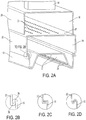
- FIG. 2A depicts a cross-sectional view of center section 12 taken along the lines 2A-2A in FIG. 1A . It should be understood that the entire coating hood is not shown in these figures.
- Center section 12 generally includes a conduit 14, an upper panel 20, a lower panel 22 and an interchangeable insert 13 that are interconnected to form an interior passageway. Air or other fluid is distributed from a source of pressurized air (not shown) connected to conduit 14 through the interior passageway of center section 12 onto glass containers (not shown) positioned beneath insert 13.
- the source of pressurized air may be a blower, a fan, or a compressed air cylinder, for example.
- the source of pressurized air may be referred to as a blower hereinafter.
- upper panel 20, lower panel 22 and insert 13 have approximately the same length and width dimensions to ensure that air will circulate across the entire length of center section 12.
- the length-wise and width-wise surfaces of upper panel 20, lower panel 22 and insert 13 may be flush.
- Upper panel 20 may be slightly shorter in length than lower panel 22 and insert 13, as shown, to accommodate a bracket 17 on the top surface of lower panel 22.
- upper panel 20 and lower panel 22 are shown as rectangular in cross-section, it should be understood that those panels may be square or circular in cross-section, for example, or any other shape that is capable of carrying air.
- conduit 14 extends in a vertical direction and has a hollow rectangular-shaped body.
- the top end of conduit 14 is either directly or indirectly connected to one or more fans/blowers that are configured to deliver air (or any other fluid) into center section 12.
- the bottom end of conduit 14 is both connected to and is in fluid communication with an opening formed in the top side of upper panel 20.
- Conduit 14 may be attached to upper panel 20 by a weld or a fastener, for example.
- conduit 14 is shown having a rectangular-shaped body, those of ordinary skill in the art will recognize that conduit 14 may be tubular or have any other shape that is capable of carrying air.
- Upper panel 20 is an elongated, three-sided, U-shaped panel comprising a horizontal wall and two depending legs forming vertical walls that extend beneath the horizontal wall.
- the horizontal wall of panel 20 includes an opening (not shown) on its top surface that is connected to the lower end of conduit 14.
- a hollow elongated upper chamber 16 is formed between the interior surfaces of upper panel 20 and a top wall 25 of lower panel 22.
- the front and rear facing surfaces of panel 20 are covered by covers 21. Covers 21 may be either separate from panel 20 or integrated with panel 20.
- a bracket 17 is fixedly positioned on the top wall of upper panel 20, and a pin 19 is mounted in bracket 17.
- pin 19 is mounted to an end of a vertically extending rod (not shown) that extends above center section 12. The rod is moved in the vertical direction in order to adjust the vertical position of the center section 12 so that center section 12 can accommodate glass containers of varying height.
- the rod is moved in the vertical direction in order to adjust the vertical position of the center section 12 so that center section 12 can accommodate glass containers of varying height.
- each vertical wall of panel 20 is connected to the upper surface of lower panel 22.
- the vertical walls of panel 20 may be attached to panel 22 by a weld or a fastener, for example.
- panels 20 and 22 may be integrated together.
- Lower panel 22 is another elongated, three-sided, U-shaped panel comprising a horizontal wall 25 and two depending legs forming vertical walls that extend beneath horizontal wall 25.
- Horizontal wall 25 includes a series of openings 23 (four rows shown) permitting the passage of air from chamber 16 to chamber 18.
- horizontal wall 25 of panel 22 may be a separate component that is removably positioned within center section 12 to change the airflow path between chambers 16 and 18.
- chamber 16 could be provided in the form of a conduit that is positioned inside of chamber 18 to deliver air or other fluid into chamber 18.
- access panel 32 is covered by access panel 32, and the rear facing surface of panel 22 (not shown) is covered by a cover (not shown).
- Access panel 32 is mounted to the front-facing surface of panel 22 by one or more fasteners 34. Access panel 32 extends to an elevation either at or below rail 26 such that access panel 32 retains insert 13 inside of center section 12.
- Insert 13 is positioned at an elevation beneath lower panel 22 such that a second hollow elongated lower chamber 18 is formed between the interior surfaces of lower panel 22 and the top-facing surface(s) of insert 13.
- Insert 13 is positioned on a mounting surface defined on the free ends of each vertical wall of lower panel 22.
- the free ends of the vertical walls of lower panel 22 are the ends of panel 22 that are unconstrained and that are not mounted to upper panel 20. More particularly, as shown in the detailed view of FIG. 2B , the free end of each vertical wall of panel 22 includes a U-shaped rail 26 in the form of a curved lip that engages with a complimentary U-shaped rail 28 that is formed on the free end of each side of insert 13. Rail 26 may also be referred to herein as a mounting surface.
- each rail may include a flat perpendicular surface or a V-shape, as shown in FIGs. 2C and 2D , respectively.
- Rails 26 and 28 are not fixedly mounted together by a weld, for example.
- insert 13 is not fixedly mounted to or integrated with panel 22. According to one aspect of the invention, no fasteners are required to mount insert 13 to panel 22. Those of ordinary skill in the art will recognize that other mounting arrangements for insert 13 exist.
- Insert 13 comprises apertures 29 that are configured to direct air or other fluid onto a specific area of a glass container (e.g., the finish of the container) during the glass coating process.
- Apertures 29 may be openings, slots, slits or perforations, for example.
- the glass container travels along the length dimension of center section 12 at a location that is either adjacent or directly adjacent lower facing surface 27 of insert 13.
- the glass containers are spaced from surface 27 by less than 5 inches. More preferably, the glass containers are spaced from surface 27 by less than 3 inches.
- insert 13 and location of apertures 29 may vary from that which is shown in FIG. 2A .
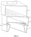
- Alternative inserts 13' and 13" are shown in FIGs. 3 and 4 , respectively, and it should be understood that further alternative designs exist.
- Insert 13 of FIG. 2A has a series of bends for accommodating a container having a wide-shaped container opening, for example.
- Insert 13' of FIG. 3 also has a series of bends for accommodating a container having a wide-shaped container opening, for example.
- Insert 13" shown in FIG. 4 is a flat sheet having no bends, and at least a portion of its surface is perforated with apertures 29. Insert 13" may be used for delivering air onto the finish of glass beer bottles, for example.
- apertures 29 defined in insert 13' are positioned at a higher elevation than apertures 29 defined in inserts 13 and 13'.
- insert 13 and 13' both extend downward to an elevation beneath the rail 26, whereas the entirety of insert 13" sits at an elevation above rail 26.
- insert 13 and panels 20 and 22 of center section 12 are optionally formed from aluminum or steel sheet metal, for example.
- those components of center section 12 may be formed from a plastic material, if so desired.
- Insert 13 may be a unitary, integral and monolithic component, as shown, that is formed from one piece of material. Insert 13 may be formed from any material that is known to those of ordinary skill in the art.
- the blowers or other source of pressurized air delivers air (or other process fluid) through conduit 14 and into upper chamber 16, as indicated by the vertical arrow in FIG. 1A .
- Upper chamber 16 acts as a manifold in that the air is uniformly distributed over the entire length of upper chamber 16.
- the air passes then through openings 23 of wall 25 and into lower chamber 18.
- Lower chamber 18 also acts as a manifold in that the air is uniformly distributed over the entire length of lower chamber 18.
- the air then passes through apertures 29 in insert 13, and the air is then directed onto the surfaces of the glass containers (e.g., the finish of the containers, which is not shown) that face the lower-facing surfaces 27 of insert 13.
- the chemical coating is not delivered through the insert 13, rather, it is sprayed onto the glass container by a separate spray device (not shown).
- insert 13' First, rails 28 of insert 13' are positioned on top of rails 26 of panel 22, and then insert 13' is slid in a forward horizontal direction until the rear end of insert 13' abuts with a rear surface (not shown) of panel 22. Panel 32 is then reinstalled to captivate insert 13' inside center section 12. The lower edge 35 of panel 32 extends to an elevation beneath the rails 28 of insert 13' so that insert 13' (or any other insert) cannot be removed without first removing panel 32.
- the insert can be hot-swapped, i.e., replaced without halting operation of the entire coating hood, with another insert in a matter of minutes, thereby minimizing downtime for the coating hood.
- the insert can be hot-swapped with another insert in less than 10 minutes. More preferably, the insert can be hot-swapped with another insert in less than 5 minutes.
- inserts 13, 13' and 13" may all be provided in the form of a kit that is provided along with center section 12. An end-user can select the appropriate insert 13, 13' and 13" for use in a particular coating operation.
Landscapes
- Chemical & Material Sciences (AREA)
- Life Sciences & Earth Sciences (AREA)
- Engineering & Computer Science (AREA)
- Chemical Kinetics & Catalysis (AREA)
- General Chemical & Material Sciences (AREA)
- Geochemistry & Mineralogy (AREA)
- Materials Engineering (AREA)
- Organic Chemistry (AREA)
- Surface Treatment Of Glass (AREA)
- Re-Forming, After-Treatment, Cutting And Transporting Of Glass Products (AREA)
- Details Of Rigid Or Semi-Rigid Containers (AREA)
Description
- This application is related to and claims the benefit of
U.S. Provisional Application No. 62/259,179 filed on November 22, 2015 - This invention relates to a coating hood for coating glass containers.
- In the process of manufacturing a glass container, the exterior surface of the glass container is typically coated with a metal-oxide coating, for example, to improve its structural integrity.
- The coating process is traditionally performed in a coating hood. Coating hoods are disclosed in
U.S. Patent Application Pub. No. 2015/0101537 ;U.S. Patent Nos. 4389234 ,5081953 ,5140940 ,5454873 ,5599369 ,5584903 ,4668268 ,4879970 ; andPCT Patent App. Pub. No. WO1996020142 . In an assembly line style operation, coating vapor is sprayed onto the exterior surface of a glass container as the glass container passes either below or under a center section of the coating hood. The coating is typically prevented from being applied to the closure region of the container, known in the art as the "finish," by an air stream that is delivered through the center section of the coating hood and onto the closure of the container. The air stream creates a buffer zone that substantially prevents the coating material from settling on the finish. - To accommodate different glass containers having their own unique size and shape (e.g., tall neck beer bottle, baby food jar, wide-mouth jar, etc.), it is often necessary to disassemble the coating hood and replace the entire center section of the coating hood with a different center section that will accommodate glass containers having a different shape and/or size. Taking the coating hood off-line for disassembly and replacement of the center section results in costly downtime.
- In view of the foregoing, there exists a need in the glass coating industry to provide an interchangeable and hot-swappable center section for a coating hood.
- According to one aspect of the invention, an apparatus for coating glass articles as from claim 1 is disclosed.
- According to another aspect of the invention, a kit for coating glass articles comprises the above-described elongated housing structure and a plurality of inserts. Each insert is configured to be removably positioned on the mounting surface, and each insert has apertures for distributing the air or other fluid from the chamber and onto a surface of the glass articles. Each insert has a different arrangement of apertures for directing the air or other fluid onto the glass articles.
- According to yet another aspect of the invention, a method for changing an airflow pattern in an apparatus for coating glass articles comprises the steps of:
- (a) moving an access panel of the apparatus to gain access to a chamber defined within the apparatus, wherein the chamber is configured to receive air or other fluid from a blower that is in fluid communication with the chamber;
- (b) removing a first insert that is positioned within the chamber from the apparatus; and
- (c) positioning a second insert into the chamber in place of the first insert, whereby each insert includes a series of apertures that direct the air or other fluid in a particular airflow pattern from the chamber and onto the glass articles positioned adjacent the insert, and the flow pattern defined by the second insert differs from the flow pattern defined by the first insert.
- The invention is best understood from the following detailed description when read in connection with the accompanying drawing. Included in the drawing are the following figures:
-
FIG. 1A depicts a perspective view of a center section of a coating hood. -
FIG. 1B depicts a perspective view of the center section ofFIG. 1A , wherein the interchangeable insert is shown partially disassembled from the remainder of the center section. -
FIG. 2A depicts a perspective cross-sectional view of the center section ofFIG. 1A taken along thelines 2A-2A inFIG. 1A . -
FIG. 2B depicts a detailed view of the connection between the insert and the center section ofFIG. 2A . -
FIGs. 2C and 2D show alternative connections between the insert and the center section. -
FIG. 3 depicts a perspective view of the center section ofFIG. 1A , shown partially cut-away, having a different interchangeable insert than is shown inFIG. 2A . -
FIG. 4 depicts a perspective view of the center section ofFIG. 1A , shown partially cut-away, having a different interchangeable insert than is shown inFIGs. 2A and3 . - The invention is best understood from the following detailed description when read in connection with the accompanying drawing figures, which shows exemplary embodiments of the invention selected for illustrative purposes. The invention will be illustrated with reference to the figures. Such figures are intended to be illustrative rather than limiting and are included herewith to facilitate the explanation of the present invention.
- This description of the exemplary embodiments is intended to be read in connection with the accompanying drawings, which are to be considered part of the entire written description. In the description, relative terms such as "lower," "upper," "horizontal," "vertical,", "above," "below," "up," "down," "top" and "bottom" as well as derivative thereof (e.g., "horizontally," "downwardly," "upwardly," etc.) should be construed to refer to the orientation as then described or as shown in the drawing under discussion. These relative terms are for convenience of description and do not require that the apparatus be constructed or operated in a particular orientation. Terms concerning attachments, coupling and the like, such as "connected" and "interconnected," refer to a relationship wherein structures are secured or attached to one another either directly or indirectly through intervening structures, as well as both removable or rigid attachments or relationships, unless expressly described otherwise.
- By way of background to the instant invention, an example of a coating hood is disclosed in
U.S. Patent Nos. 5081953 and5584903 . The center section of the coating hood ofU.S. Patent No. 5584903 , for example, is represented by item number 10. This invention relates to the center section of a coating hood, as is described hereinafter. -
FIG. 1A depicts a perspective view of acenter section 12 of a coating hood, according to one example of the invention.FIG. 1B depicts a perspective view ofcenter section 12 ofFIG. 1A , wherein theinterchangeable insert 13 is shown partially disassembled from the remainder of thecenter section 12.FIG. 2A depicts a cross-sectional view ofcenter section 12 taken along thelines 2A-2A inFIG. 1A . It should be understood that the entire coating hood is not shown in these figures. -
Center section 12 generally includes aconduit 14, anupper panel 20, alower panel 22 and aninterchangeable insert 13 that are interconnected to form an interior passageway. Air or other fluid is distributed from a source of pressurized air (not shown) connected toconduit 14 through the interior passageway ofcenter section 12 onto glass containers (not shown) positioned beneathinsert 13. The source of pressurized air may be a blower, a fan, or a compressed air cylinder, for example. The source of pressurized air may be referred to as a blower hereinafter. - Preferably,
upper panel 20,lower panel 22 and insert 13 have approximately the same length and width dimensions to ensure that air will circulate across the entire length ofcenter section 12. The length-wise and width-wise surfaces ofupper panel 20,lower panel 22 and insert 13 may be flush.Upper panel 20 may be slightly shorter in length thanlower panel 22 andinsert 13, as shown, to accommodate abracket 17 on the top surface oflower panel 22. Whileupper panel 20 andlower panel 22 are shown as rectangular in cross-section, it should be understood that those panels may be square or circular in cross-section, for example, or any other shape that is capable of carrying air. - Referring now to the individual components of
center section 12,conduit 14 extends in a vertical direction and has a hollow rectangular-shaped body. The top end ofconduit 14 is either directly or indirectly connected to one or more fans/blowers that are configured to deliver air (or any other fluid) intocenter section 12. The bottom end ofconduit 14 is both connected to and is in fluid communication with an opening formed in the top side ofupper panel 20.Conduit 14 may be attached toupper panel 20 by a weld or a fastener, for example. Althoughconduit 14 is shown having a rectangular-shaped body, those of ordinary skill in the art will recognize thatconduit 14 may be tubular or have any other shape that is capable of carrying air. -
Upper panel 20 is an elongated, three-sided, U-shaped panel comprising a horizontal wall and two depending legs forming vertical walls that extend beneath the horizontal wall. The horizontal wall ofpanel 20 includes an opening (not shown) on its top surface that is connected to the lower end ofconduit 14. A hollow elongatedupper chamber 16 is formed between the interior surfaces ofupper panel 20 and atop wall 25 oflower panel 22. The front and rear facing surfaces ofpanel 20 are covered by covers 21.Covers 21 may be either separate frompanel 20 or integrated withpanel 20. - A
bracket 17 is fixedly positioned on the top wall ofupper panel 20, and apin 19 is mounted inbracket 17. In use,pin 19 is mounted to an end of a vertically extending rod (not shown) that extends abovecenter section 12. The rod is moved in the vertical direction in order to adjust the vertical position of thecenter section 12 so thatcenter section 12 can accommodate glass containers of varying height. Those skilled in the art will recognize that other ways exist to adjust the vertical position ofcenter section 12. - The lower end of each vertical wall of
panel 20 is connected to the upper surface oflower panel 22. The vertical walls ofpanel 20 may be attached topanel 22 by a weld or a fastener, for example. Alternatively,panels -
Lower panel 22 is another elongated, three-sided, U-shaped panel comprising ahorizontal wall 25 and two depending legs forming vertical walls that extend beneathhorizontal wall 25.Horizontal wall 25 includes a series of openings 23 (four rows shown) permitting the passage of air fromchamber 16 tochamber 18. Although not shown,horizontal wall 25 ofpanel 22 may be a separate component that is removably positioned withincenter section 12 to change the airflow path betweenchambers panel 20,chamber 16 could be provided in the form of a conduit that is positioned inside ofchamber 18 to deliver air or other fluid intochamber 18. - Referring back to
FIG. 1A , the front facing surface oflower panel 22 is covered byaccess panel 32, and the rear facing surface of panel 22 (not shown) is covered by a cover (not shown).Access panel 32 is mounted to the front-facing surface ofpanel 22 by one ormore fasteners 34.Access panel 32 extends to an elevation either at or belowrail 26 such thataccess panel 32 retainsinsert 13 inside ofcenter section 12. -
Insert 13 is positioned at an elevation beneathlower panel 22 such that a second hollow elongatedlower chamber 18 is formed between the interior surfaces oflower panel 22 and the top-facing surface(s) ofinsert 13.Insert 13 is positioned on a mounting surface defined on the free ends of each vertical wall oflower panel 22. The free ends of the vertical walls oflower panel 22 are the ends ofpanel 22 that are unconstrained and that are not mounted toupper panel 20. More particularly, as shown in the detailed view ofFIG. 2B , the free end of each vertical wall ofpanel 22 includes aU-shaped rail 26 in the form of a curved lip that engages with a complimentaryU-shaped rail 28 that is formed on the free end of each side ofinsert 13.Rail 26 may also be referred to herein as a mounting surface. - The geometry of
rails FIGs. 2C and 2D , respectively.Rails - Preferably, insert 13 is not fixedly mounted to or integrated with
panel 22. According to one aspect of the invention, no fasteners are required to mountinsert 13 topanel 22. Those of ordinary skill in the art will recognize that other mounting arrangements forinsert 13 exist. -
Insert 13 comprisesapertures 29 that are configured to direct air or other fluid onto a specific area of a glass container (e.g., the finish of the container) during the glass coating process.Apertures 29 may be openings, slots, slits or perforations, for example. During that process, the glass container travels along the length dimension ofcenter section 12 at a location that is either adjacent or directly adjacent lower facingsurface 27 ofinsert 13. Preferably, the glass containers are spaced fromsurface 27 by less than 5 inches. More preferably, the glass containers are spaced fromsurface 27 by less than 3 inches. - The geometry of
insert 13 and location ofapertures 29 may vary from that which is shown inFIG. 2A . Alternative inserts 13' and 13" are shown inFIGs. 3 and4 , respectively, and it should be understood that further alternative designs exist. -
Insert 13 ofFIG. 2A has a series of bends for accommodating a container having a wide-shaped container opening, for example. Insert 13' ofFIG. 3 also has a series of bends for accommodating a container having a wide-shaped container opening, for example.Insert 13" shown inFIG. 4 is a flat sheet having no bends, and at least a portion of its surface is perforated withapertures 29.Insert 13" may be used for delivering air onto the finish of glass beer bottles, for example. For comparison purposes,apertures 29 defined in insert 13' are positioned at a higher elevation thanapertures 29 defined ininserts 13 and 13'. Also, insert 13 and 13' both extend downward to an elevation beneath therail 26, whereas the entirety ofinsert 13" sits at an elevation aboverail 26. - The
insert 13 andpanels center section 12 are optionally formed from aluminum or steel sheet metal, for example. Alternatively, those components ofcenter section 12 may be formed from a plastic material, if so desired.Insert 13 may be a unitary, integral and monolithic component, as shown, that is formed from one piece of material.Insert 13 may be formed from any material that is known to those of ordinary skill in the art. - During the glass container coating process, the blowers or other source of pressurized air (not shown) delivers air (or other process fluid) through
conduit 14 and intoupper chamber 16, as indicated by the vertical arrow inFIG. 1A .Upper chamber 16 acts as a manifold in that the air is uniformly distributed over the entire length ofupper chamber 16. The air passes then through openings 23 ofwall 25 and intolower chamber 18.Lower chamber 18 also acts as a manifold in that the air is uniformly distributed over the entire length oflower chamber 18. The air then passes throughapertures 29 ininsert 13, and the air is then directed onto the surfaces of the glass containers (e.g., the finish of the containers, which is not shown) that face the lower-facingsurfaces 27 ofinsert 13. It should be understood that the chemical coating is not delivered through theinsert 13, rather, it is sprayed onto the glass container by a separate spray device (not shown). - To remove an existing
insert 13 and install a different insert 13' for accommodating glass containers having a different shape and/or size, it is necessary to first removepanel 32 that is mounted to the front-facing surface ofpanel 22 by one ormore fasteners 34.Panel 32 is omitted fromFIG. 1B becauseinsert 13 is shown in the process of being installed ontocenter section 12. Oncepanel 32 is removed, insert 13 is simply slid in a reverse horizontal direction (seeFIG. 1B ) away fromcenter unit 12 until it is no longer positioned incenter unit 12. The new insert 13' is then ready to be installed intocenter unit 12. First, rails 28 of insert 13' are positioned on top ofrails 26 ofpanel 22, and then insert 13' is slid in a forward horizontal direction until the rear end of insert 13' abuts with a rear surface (not shown) ofpanel 22.Panel 32 is then reinstalled to captivate insert 13'inside center section 12. Thelower edge 35 ofpanel 32 extends to an elevation beneath therails 28 of insert 13' so that insert 13' (or any other insert) cannot be removed without first removingpanel 32. The insert can be hot-swapped, i.e., replaced without halting operation of the entire coating hood, with another insert in a matter of minutes, thereby minimizing downtime for the coating hood. Preferably, the insert can be hot-swapped with another insert in less than 10 minutes. More preferably, the insert can be hot-swapped with another insert in less than 5 minutes. - According to one aspect of the invention, inserts 13, 13' and 13" may all be provided in the form of a kit that is provided along with
center section 12. An end-user can select theappropriate insert - It should be understood that the above described method is not limited to any particular step or sequence of steps.
- Within this specification embodiments have been described in a way which enables a clear and concise specification to be written, but it is intended and will be appreciated that embodiments may be variously combined or separated without parting from the invention. For example, it will be appreciated that all preferred features described herein are applicable to all aspect of the invention described herein.
Claims (18)
- An apparatus (12) for coating glass articles comprising:an elongated housing structure (22) having (i) two or more walls (25) defining an interior chamber (18) for receiving pressurized air or other fluid, and (ii) a mounting surface (26) defined along at least a portion of one of the walls; andan insert (13) removably configured on the mounting surface (26), the insert (13) having apertures (29) for distributing the pressurized air or other fluid from the chamber (18) onto a surface of the glass articles that are positioned adjacent the insert (13),wherein the housing structure (22) comprises a panel having a first wall (25) and two perpendicular walls extending substantially perpendicularly from opposing sides of the first wall (25), and wherein the mounting surface (26) is defined on a free end of each perpendicular wall, the first wall (25) and the perpendicular walls comprising the two or more walls of the housing structure (22), andwherein the insert (13) extends away from the chamber (18) to an elevation beneath the housing structure (22).
- The apparatus of claim 1, wherein the mounting surface (26) extends horizontally and perpendicular to the perpendicular wall of the elongated housing structure from which the mounting surface (26) depends.
- The apparatus of claim 1, wherein each mounting surface (26) is a curved lip that is configured to engage with a complimentary surface (28) of the insert (13) to retain the insert (13) on the housing structure (22).
- The apparatus of claim 1, wherein the first wall (25) of the housing structure includes openings (23) for directing air into the chamber (18).
- The apparatus of claim 4 further comprising a second chamber (16) positioned adjacent said chamber (18), wherein said chambers are in fluid communication with each other by the openings (23) formed in the first wall (25).
- The apparatus of claim 5, wherein the second chamber (16) is at least partially defined by a second panel (20) that is mounted to the panel (22).
- The apparatus of claim 6 further comprising a conduit (14) that is mounted to the second panel (20), the conduit (14) being fluidly connected to a source of pressurized air to deliver air through the conduit (14) and into the second chamber (16).
- The apparatus of claim 1 further comprising an access panel (32) that is mounted to the housing structure (22) for constraining the insert (13) within the chamber (18), wherein the insert (13) is removable from the apparatus (12) upon either moving or removing the access panel (32).
- The apparatus of claim 1, wherein the insert (13) is an integral component formed from sheetmetal or plastic.
- The apparatus of claim 1, wherein the insert (13) is hot swappable.
- The apparatus of claim 1 further comprising a second chamber (16) that is positioned to deliver the pressurized air into said chamber (18).
- The apparatus of claim 11
wherein the second chamber (16) is positioned above, below, adjacent or within the chamber (18). - A kit for coating glass articles comprising:an elongated housing structure (22) having (i) two or more walls (25) defining an interior chamber (18) for receiving pressurized air or other fluid, and (ii) a mounting surface (26) defined along at least a portion of one of the walls; anda plurality of inserts (13, 13', 13"), each insert (13, 13', 13") being configured to be removably positioned on the mounting surface (26) of the elongated housing structure (22), and each insert (13, 13', 13") having apertures (29) for distributing the air or other fluid from the chamber (18) onto a surface of the glass articles, wherein each insert (13, 13', 13") has a different arrangement of apertures (29) for directing the air or other fluid onto the glass articles.
- The kit of claim 13
wherein one insert (13) of the plurality of inserts (13, 13', 13") extends to a different elevation with respect to the mounting surface than another insert (13") of the plurality of inserts (13, 13', 13"). - The kit of claim 13
wherein the apertures (29) of one insert (13) of the plurality of inserts (13, 13', 13") are positioned at a different elevation from the apertures (29) of another insert (13") of the plurality of inserts. - 17 A method for changing an airflow pattern in an apparatus (12) for coating glass articles, the method comprising:(a) moving an access panel (32) of the apparatus (12) to gain access to a chamber (18) defined within the apparatus (12), wherein the chamber (18) is configured to receive pressurized air or other fluid;(b) removing a first insert (13) that is positioned within the chamber (18) from the apparatus (12); and(c) positioning a second insert (13') into the chamber (18) in place of the first insert (13), whereby each insert (13, 13') includes a series of apertures (29) that direct the air or other fluid in a particular airflow pattern from the chamber (18) and onto the glass articles positioned adjacent the insert (13), and the flow pattern defined by the second insert (13') differs from the flow pattern defined by the first insert (13).
- The method of claim 16
wherein prior to step (a), the method further comprises operating a source of pressurized air to deliver pressurized air through the first insert (13) and onto the glass articles. - The method of claim 16
wherein after step (c), the method further comprises returning the access panel (32) to its initial position and operating the source of pressurized air to deliver pressurized air through the second insert (13') and onto the glass articles.
Applications Claiming Priority (2)
| Application Number | Priority Date | Filing Date | Title |
|---|---|---|---|
| US201562259179P | 2015-11-24 | 2015-11-24 | |
| PCT/US2016/062838 WO2017091470A1 (en) | 2015-11-24 | 2016-11-18 | Interchangable center section for glass coating hood |
Publications (3)
| Publication Number | Publication Date |
|---|---|
| EP3380253A1 EP3380253A1 (en) | 2018-10-03 |
| EP3380253A4 EP3380253A4 (en) | 2019-05-22 |
| EP3380253B1 true EP3380253B1 (en) | 2021-12-22 |
Family
ID=58764294
Family Applications (1)
| Application Number | Title | Priority Date | Filing Date |
|---|---|---|---|
| EP16869110.3A Not-in-force EP3380253B1 (en) | 2015-11-24 | 2016-11-18 | Interchangable center section for glass coating hood |
Country Status (6)
| Country | Link |
|---|---|
| US (1) | US10773264B2 (en) |
| EP (1) | EP3380253B1 (en) |
| CN (1) | CN108290174B (en) |
| AR (1) | AR106781A1 (en) |
| MX (1) | MX2018006279A (en) |
| WO (1) | WO2017091470A1 (en) |
Family Cites Families (18)
| Publication number | Priority date | Publication date | Assignee | Title |
|---|---|---|---|---|
| US3876410A (en) * | 1969-12-24 | 1975-04-08 | Ball Brothers Co Inc | Method of applying durable lubricous coatings on glass containers |
| US3909004A (en) * | 1974-01-08 | 1975-09-30 | Tony J Vella | Putter having circular level |
| US3989004A (en) | 1974-08-15 | 1976-11-02 | Ball Corporation | Apparatus for applying durable lubricous coatings to newly formed vitreous surfaces |
| US4022601A (en) * | 1975-06-02 | 1977-05-10 | Ppg Industries, Inc. | Method and apparatus for coating a glass substrate |
| US4389234A (en) | 1982-03-18 | 1983-06-21 | M&T Chemicals Inc. | Glass coating hood and method of spray coating glassware |
| US4668268A (en) * | 1984-12-20 | 1987-05-26 | M&T Chemicals Inc. | Coating hood with air flow guide for minimizing deposition of coating compound on finish of containers |
| US4879970A (en) | 1987-04-21 | 1989-11-14 | M&T Chemicals Inc. | Coating hood for applying coating compound on containers |
| US5136976A (en) * | 1989-10-27 | 1992-08-11 | Atochem North America, Inc. | Method and means for controlled-profile coating of glass containers |
| US5081953A (en) | 1989-10-27 | 1992-01-21 | Atochem North America, Inc. | Center section for coating hood for glass containers |
| US5140940A (en) | 1991-01-08 | 1992-08-25 | Atochem North America, Inc. | Apparatus for depositing a metal-oxide coating on glass articles |
| CA2068100C (en) * | 1991-06-20 | 2000-07-18 | Roger T. Guthrie | Permeable attenuating distributor for glass-coating apparatus |
| US5599369A (en) | 1994-04-29 | 1997-02-04 | Owens-Brockway Glass Container Inc. | Hood for metal-oxide vapor coating glass containers |
| US5454873A (en) | 1994-05-20 | 1995-10-03 | Scholes; Addison B. | Cold end glassware coating apparatus |
| DE4446217C2 (en) | 1994-12-23 | 1997-10-09 | Gewerk Keramchemie | Device for the surface treatment of hollow glass bodies |
| DE69824357T2 (en) * | 1997-09-24 | 2005-06-16 | Kirin Beer K.K. | Method and device for producing and coating bottles |
| AU7863800A (en) * | 1999-10-05 | 2001-05-10 | Cardinal Companies, Lp | Glass container coating hood |
| BR112014026734A2 (en) | 2012-04-27 | 2017-06-27 | Arkema Inc | dome for the coating of glass containers by the deposition of metal oxide vapor |
| CN103496856A (en) * | 2013-09-06 | 2014-01-08 | 浙江大学宁波理工学院 | Hinged spraying furnace and spraying method for glass surface transparent conductive film |
-
2016
- 2016-11-18 CN CN201680067281.XA patent/CN108290174B/en active Active
- 2016-11-18 US US15/777,687 patent/US10773264B2/en active Active
- 2016-11-18 WO PCT/US2016/062838 patent/WO2017091470A1/en not_active Ceased
- 2016-11-18 MX MX2018006279A patent/MX2018006279A/en unknown
- 2016-11-18 EP EP16869110.3A patent/EP3380253B1/en not_active Not-in-force
- 2016-11-22 AR ARP160103573A patent/AR106781A1/en active IP Right Grant
Non-Patent Citations (1)
| Title |
|---|
| None * |
Also Published As
| Publication number | Publication date |
|---|---|
| WO2017091470A1 (en) | 2017-06-01 |
| CN108290174B (en) | 2021-04-06 |
| US20180345301A1 (en) | 2018-12-06 |
| CN108290174A (en) | 2018-07-17 |
| MX2018006279A (en) | 2018-09-07 |
| EP3380253A4 (en) | 2019-05-22 |
| EP3380253A1 (en) | 2018-10-03 |
| AR106781A1 (en) | 2018-02-14 |
| US10773264B2 (en) | 2020-09-15 |
Similar Documents
| Publication | Publication Date | Title |
|---|---|---|
| US11731154B2 (en) | Modular hood for coating glass containers including removable dividers for affecting air flow through the hood | |
| JP2011510259A (en) | Exhaust booster | |
| PL2034872T3 (en) | Apparatus for preparing food and air guide member therefor | |
| CN105457818B (en) | Equipment for coating to be applied to product | |
| JP6407034B2 (en) | Heat treatment device | |
| US20230008929A1 (en) | Assembly of a Containment Means with an Aseptic Working Chamber | |
| US20200284534A1 (en) | Heat exchanger spray tub | |
| CN111432993A (en) | Distributor mist management component | |
| CN107847961A (en) | painting room | |
| US10173918B2 (en) | Method for lubricating molten glass forming molds and machine using such molds | |
| KR101708183B1 (en) | Injection apparatus for agricultural pesticide scattering machine | |
| US10773264B2 (en) | Interchangable center section for glass coating hood | |
| CN104107770A (en) | Method and apparatus for applying paint on basically flat parts | |
| CA2661375A1 (en) | Cleaning device including a flood chamber | |
| WO2018153041A1 (en) | Cache device and liquid crystal screen production line | |
| JP6418830B2 (en) | Cooling device and multi-chamber heat treatment device | |
| CN1854329B (en) | Device for coating a substrate and module | |
| JP2002336749A (en) | Circulating coating booth apparatus for automobile | |
| JP5085791B1 (en) | Spraying equipment | |
| JP2003156241A (en) | Air curtain forming device | |
| US20180051891A1 (en) | Commercial cooking oven with combustion divider | |
| JP6296564B2 (en) | Showcase | |
| CN110754960A (en) | Heating structure of baking cooking device | |
| JP2010084947A (en) | Rapid heat treatment device and nozzle for the rapid heat treatment device | |
| US10578360B2 (en) | Drying apparatus and drying method using the drying apparatus |
Legal Events
| Date | Code | Title | Description |
|---|---|---|---|
| STAA | Information on the status of an ep patent application or granted ep patent |
Free format text: STATUS: THE INTERNATIONAL PUBLICATION HAS BEEN MADE |
|
| PUAI | Public reference made under article 153(3) epc to a published international application that has entered the european phase |
Free format text: ORIGINAL CODE: 0009012 |
|
| STAA | Information on the status of an ep patent application or granted ep patent |
Free format text: STATUS: REQUEST FOR EXAMINATION WAS MADE |
|
| 17P | Request for examination filed |
Effective date: 20180524 |
|
| AK | Designated contracting states |
Kind code of ref document: A1 Designated state(s): AL AT BE BG CH CY CZ DE DK EE ES FI FR GB GR HR HU IE IS IT LI LT LU LV MC MK MT NL NO PL PT RO RS SE SI SK SM TR |
|
| AX | Request for extension of the european patent |
Extension state: BA ME |
|
| DAV | Request for validation of the european patent (deleted) | ||
| DAX | Request for extension of the european patent (deleted) | ||
| REG | Reference to a national code |
Ref country code: DE Ref legal event code: R079 Ref document number: 602016067712 Country of ref document: DE Free format text: PREVIOUS MAIN CLASS: B05B0015040000 Ipc: C03C0017000000 |
|
| A4 | Supplementary search report drawn up and despatched |
Effective date: 20190426 |
|
| RIC1 | Information provided on ipc code assigned before grant |
Ipc: C03C 17/245 20060101ALI20190418BHEP Ipc: B05B 12/18 20180101ALI20190418BHEP Ipc: C03C 17/00 20060101AFI20190418BHEP |
|
| STAA | Information on the status of an ep patent application or granted ep patent |
Free format text: STATUS: EXAMINATION IS IN PROGRESS |
|
| 17Q | First examination report despatched |
Effective date: 20200817 |
|
| GRAP | Despatch of communication of intention to grant a patent |
Free format text: ORIGINAL CODE: EPIDOSNIGR1 |
|
| STAA | Information on the status of an ep patent application or granted ep patent |
Free format text: STATUS: GRANT OF PATENT IS INTENDED |
|
| INTG | Intention to grant announced |
Effective date: 20210705 |
|
| GRAS | Grant fee paid |
Free format text: ORIGINAL CODE: EPIDOSNIGR3 |
|
| GRAA | (expected) grant |
Free format text: ORIGINAL CODE: 0009210 |
|
| STAA | Information on the status of an ep patent application or granted ep patent |
Free format text: STATUS: THE PATENT HAS BEEN GRANTED |
|
| AK | Designated contracting states |
Kind code of ref document: B1 Designated state(s): AL AT BE BG CH CY CZ DE DK EE ES FI FR GB GR HR HU IE IS IT LI LT LU LV MC MK MT NL NO PL PT RO RS SE SI SK SM TR |
|
| REG | Reference to a national code |
Ref country code: GB Ref legal event code: FG4D |
|
| REG | Reference to a national code |
Ref country code: CH Ref legal event code: EP |
|
| REG | Reference to a national code |
Ref country code: DE Ref legal event code: R096 Ref document number: 602016067712 Country of ref document: DE |
|
| REG | Reference to a national code |
Ref country code: AT Ref legal event code: REF Ref document number: 1456968 Country of ref document: AT Kind code of ref document: T Effective date: 20220115 |
|
| REG | Reference to a national code |
Ref country code: IE Ref legal event code: FG4D |
|
| REG | Reference to a national code |
Ref country code: NL Ref legal event code: FP |
|
| REG | Reference to a national code |
Ref country code: LT Ref legal event code: MG9D |
|
| PG25 | Lapsed in a contracting state [announced via postgrant information from national office to epo] |
Ref country code: RS Free format text: LAPSE BECAUSE OF FAILURE TO SUBMIT A TRANSLATION OF THE DESCRIPTION OR TO PAY THE FEE WITHIN THE PRESCRIBED TIME-LIMIT Effective date: 20211222 Ref country code: LT Free format text: LAPSE BECAUSE OF FAILURE TO SUBMIT A TRANSLATION OF THE DESCRIPTION OR TO PAY THE FEE WITHIN THE PRESCRIBED TIME-LIMIT Effective date: 20211222 Ref country code: FI Free format text: LAPSE BECAUSE OF FAILURE TO SUBMIT A TRANSLATION OF THE DESCRIPTION OR TO PAY THE FEE WITHIN THE PRESCRIBED TIME-LIMIT Effective date: 20211222 Ref country code: BG Free format text: LAPSE BECAUSE OF FAILURE TO SUBMIT A TRANSLATION OF THE DESCRIPTION OR TO PAY THE FEE WITHIN THE PRESCRIBED TIME-LIMIT Effective date: 20220322 |
|
| REG | Reference to a national code |
Ref country code: AT Ref legal event code: MK05 Ref document number: 1456968 Country of ref document: AT Kind code of ref document: T Effective date: 20211222 |
|
| PG25 | Lapsed in a contracting state [announced via postgrant information from national office to epo] |
Ref country code: SE Free format text: LAPSE BECAUSE OF FAILURE TO SUBMIT A TRANSLATION OF THE DESCRIPTION OR TO PAY THE FEE WITHIN THE PRESCRIBED TIME-LIMIT Effective date: 20211222 Ref country code: NO Free format text: LAPSE BECAUSE OF FAILURE TO SUBMIT A TRANSLATION OF THE DESCRIPTION OR TO PAY THE FEE WITHIN THE PRESCRIBED TIME-LIMIT Effective date: 20220322 Ref country code: LV Free format text: LAPSE BECAUSE OF FAILURE TO SUBMIT A TRANSLATION OF THE DESCRIPTION OR TO PAY THE FEE WITHIN THE PRESCRIBED TIME-LIMIT Effective date: 20211222 Ref country code: HR Free format text: LAPSE BECAUSE OF FAILURE TO SUBMIT A TRANSLATION OF THE DESCRIPTION OR TO PAY THE FEE WITHIN THE PRESCRIBED TIME-LIMIT Effective date: 20211222 Ref country code: GR Free format text: LAPSE BECAUSE OF FAILURE TO SUBMIT A TRANSLATION OF THE DESCRIPTION OR TO PAY THE FEE WITHIN THE PRESCRIBED TIME-LIMIT Effective date: 20220323 |
|
| PG25 | Lapsed in a contracting state [announced via postgrant information from national office to epo] |
Ref country code: SM Free format text: LAPSE BECAUSE OF FAILURE TO SUBMIT A TRANSLATION OF THE DESCRIPTION OR TO PAY THE FEE WITHIN THE PRESCRIBED TIME-LIMIT Effective date: 20211222 Ref country code: SK Free format text: LAPSE BECAUSE OF FAILURE TO SUBMIT A TRANSLATION OF THE DESCRIPTION OR TO PAY THE FEE WITHIN THE PRESCRIBED TIME-LIMIT Effective date: 20211222 Ref country code: RO Free format text: LAPSE BECAUSE OF FAILURE TO SUBMIT A TRANSLATION OF THE DESCRIPTION OR TO PAY THE FEE WITHIN THE PRESCRIBED TIME-LIMIT Effective date: 20211222 Ref country code: PT Free format text: LAPSE BECAUSE OF FAILURE TO SUBMIT A TRANSLATION OF THE DESCRIPTION OR TO PAY THE FEE WITHIN THE PRESCRIBED TIME-LIMIT Effective date: 20220422 Ref country code: ES Free format text: LAPSE BECAUSE OF FAILURE TO SUBMIT A TRANSLATION OF THE DESCRIPTION OR TO PAY THE FEE WITHIN THE PRESCRIBED TIME-LIMIT Effective date: 20211222 Ref country code: EE Free format text: LAPSE BECAUSE OF FAILURE TO SUBMIT A TRANSLATION OF THE DESCRIPTION OR TO PAY THE FEE WITHIN THE PRESCRIBED TIME-LIMIT Effective date: 20211222 Ref country code: CZ Free format text: LAPSE BECAUSE OF FAILURE TO SUBMIT A TRANSLATION OF THE DESCRIPTION OR TO PAY THE FEE WITHIN THE PRESCRIBED TIME-LIMIT Effective date: 20211222 |
|
| PG25 | Lapsed in a contracting state [announced via postgrant information from national office to epo] |
Ref country code: PL Free format text: LAPSE BECAUSE OF FAILURE TO SUBMIT A TRANSLATION OF THE DESCRIPTION OR TO PAY THE FEE WITHIN THE PRESCRIBED TIME-LIMIT Effective date: 20211222 Ref country code: AT Free format text: LAPSE BECAUSE OF FAILURE TO SUBMIT A TRANSLATION OF THE DESCRIPTION OR TO PAY THE FEE WITHIN THE PRESCRIBED TIME-LIMIT Effective date: 20211222 |
|
| REG | Reference to a national code |
Ref country code: DE Ref legal event code: R097 Ref document number: 602016067712 Country of ref document: DE |
|
| PG25 | Lapsed in a contracting state [announced via postgrant information from national office to epo] |
Ref country code: IS Free format text: LAPSE BECAUSE OF FAILURE TO SUBMIT A TRANSLATION OF THE DESCRIPTION OR TO PAY THE FEE WITHIN THE PRESCRIBED TIME-LIMIT Effective date: 20220422 |
|
| PLBE | No opposition filed within time limit |
Free format text: ORIGINAL CODE: 0009261 |
|
| STAA | Information on the status of an ep patent application or granted ep patent |
Free format text: STATUS: NO OPPOSITION FILED WITHIN TIME LIMIT |
|
| PG25 | Lapsed in a contracting state [announced via postgrant information from national office to epo] |
Ref country code: DK Free format text: LAPSE BECAUSE OF FAILURE TO SUBMIT A TRANSLATION OF THE DESCRIPTION OR TO PAY THE FEE WITHIN THE PRESCRIBED TIME-LIMIT Effective date: 20211222 Ref country code: AL Free format text: LAPSE BECAUSE OF FAILURE TO SUBMIT A TRANSLATION OF THE DESCRIPTION OR TO PAY THE FEE WITHIN THE PRESCRIBED TIME-LIMIT Effective date: 20211222 |
|
| 26N | No opposition filed |
Effective date: 20220923 |
|
| PG25 | Lapsed in a contracting state [announced via postgrant information from national office to epo] |
Ref country code: SI Free format text: LAPSE BECAUSE OF FAILURE TO SUBMIT A TRANSLATION OF THE DESCRIPTION OR TO PAY THE FEE WITHIN THE PRESCRIBED TIME-LIMIT Effective date: 20211222 |
|
| PG25 | Lapsed in a contracting state [announced via postgrant information from national office to epo] |
Ref country code: IT Free format text: LAPSE BECAUSE OF FAILURE TO SUBMIT A TRANSLATION OF THE DESCRIPTION OR TO PAY THE FEE WITHIN THE PRESCRIBED TIME-LIMIT Effective date: 20211222 |
|
| REG | Reference to a national code |
Ref country code: DE Ref legal event code: R119 Ref document number: 602016067712 Country of ref document: DE |
|
| PG25 | Lapsed in a contracting state [announced via postgrant information from national office to epo] |
Ref country code: MC Free format text: LAPSE BECAUSE OF FAILURE TO SUBMIT A TRANSLATION OF THE DESCRIPTION OR TO PAY THE FEE WITHIN THE PRESCRIBED TIME-LIMIT Effective date: 20211222 |
|
| REG | Reference to a national code |
Ref country code: CH Ref legal event code: PL |
|
| GBPC | Gb: european patent ceased through non-payment of renewal fee |
Effective date: 20221118 |
|
| REG | Reference to a national code |
Ref country code: BE Ref legal event code: MM Effective date: 20221130 |
|
| PG25 | Lapsed in a contracting state [announced via postgrant information from national office to epo] |
Ref country code: LI Free format text: LAPSE BECAUSE OF NON-PAYMENT OF DUE FEES Effective date: 20221130 Ref country code: CH Free format text: LAPSE BECAUSE OF NON-PAYMENT OF DUE FEES Effective date: 20221130 |
|
| PG25 | Lapsed in a contracting state [announced via postgrant information from national office to epo] |
Ref country code: LU Free format text: LAPSE BECAUSE OF NON-PAYMENT OF DUE FEES Effective date: 20221118 |
|
| PG25 | Lapsed in a contracting state [announced via postgrant information from national office to epo] |
Ref country code: IE Free format text: LAPSE BECAUSE OF NON-PAYMENT OF DUE FEES Effective date: 20221118 Ref country code: GB Free format text: LAPSE BECAUSE OF NON-PAYMENT OF DUE FEES Effective date: 20221118 Ref country code: DE Free format text: LAPSE BECAUSE OF NON-PAYMENT OF DUE FEES Effective date: 20230601 |
|
| PG25 | Lapsed in a contracting state [announced via postgrant information from national office to epo] |
Ref country code: BE Free format text: LAPSE BECAUSE OF NON-PAYMENT OF DUE FEES Effective date: 20221130 |
|
| PGFP | Annual fee paid to national office [announced via postgrant information from national office to epo] |
Ref country code: NL Payment date: 20231013 Year of fee payment: 8 Ref country code: FR Payment date: 20230929 Year of fee payment: 8 |
|
| PG25 | Lapsed in a contracting state [announced via postgrant information from national office to epo] |
Ref country code: HU Free format text: LAPSE BECAUSE OF FAILURE TO SUBMIT A TRANSLATION OF THE DESCRIPTION OR TO PAY THE FEE WITHIN THE PRESCRIBED TIME-LIMIT; INVALID AB INITIO Effective date: 20161118 |
|
| PG25 | Lapsed in a contracting state [announced via postgrant information from national office to epo] |
Ref country code: CY Free format text: LAPSE BECAUSE OF FAILURE TO SUBMIT A TRANSLATION OF THE DESCRIPTION OR TO PAY THE FEE WITHIN THE PRESCRIBED TIME-LIMIT Effective date: 20211222 |
|
| PG25 | Lapsed in a contracting state [announced via postgrant information from national office to epo] |
Ref country code: MK Free format text: LAPSE BECAUSE OF FAILURE TO SUBMIT A TRANSLATION OF THE DESCRIPTION OR TO PAY THE FEE WITHIN THE PRESCRIBED TIME-LIMIT Effective date: 20211222 |
|
| PG25 | Lapsed in a contracting state [announced via postgrant information from national office to epo] |
Ref country code: MT Free format text: LAPSE BECAUSE OF FAILURE TO SUBMIT A TRANSLATION OF THE DESCRIPTION OR TO PAY THE FEE WITHIN THE PRESCRIBED TIME-LIMIT Effective date: 20211222 |
|
| REG | Reference to a national code |
Ref country code: NL Ref legal event code: MM Effective date: 20241201 |
|
| PG25 | Lapsed in a contracting state [announced via postgrant information from national office to epo] |
Ref country code: NL Free format text: LAPSE BECAUSE OF NON-PAYMENT OF DUE FEES Effective date: 20241201 |
|
| PG25 | Lapsed in a contracting state [announced via postgrant information from national office to epo] |
Ref country code: FR Free format text: LAPSE BECAUSE OF NON-PAYMENT OF DUE FEES Effective date: 20241130 |
|
| PG25 | Lapsed in a contracting state [announced via postgrant information from national office to epo] |
Ref country code: TR Free format text: LAPSE BECAUSE OF FAILURE TO SUBMIT A TRANSLATION OF THE DESCRIPTION OR TO PAY THE FEE WITHIN THE PRESCRIBED TIME-LIMIT Effective date: 20211222 |