EP3379885A1 - Base station apparatus and communication control method - Google Patents
Base station apparatus and communication control method Download PDFInfo
- Publication number
- EP3379885A1 EP3379885A1 EP18170941.1A EP18170941A EP3379885A1 EP 3379885 A1 EP3379885 A1 EP 3379885A1 EP 18170941 A EP18170941 A EP 18170941A EP 3379885 A1 EP3379885 A1 EP 3379885A1
- Authority
- EP
- European Patent Office
- Prior art keywords
- base station
- station apparatus
- interference amount
- uplink
- frequency
- Prior art date
- Legal status (The legal status is an assumption and is not a legal conclusion. Google has not performed a legal analysis and makes no representation as to the accuracy of the status listed.)
- Granted
Links
Images


Classifications
-
- H—ELECTRICITY
- H04—ELECTRIC COMMUNICATION TECHNIQUE
- H04W—WIRELESS COMMUNICATION NETWORKS
- H04W88/00—Devices specially adapted for wireless communication networks, e.g. terminals, base stations or access point devices
- H04W88/08—Access point devices
-
- H—ELECTRICITY
- H04—ELECTRIC COMMUNICATION TECHNIQUE
- H04W—WIRELESS COMMUNICATION NETWORKS
- H04W72/00—Local resource management
- H04W72/50—Allocation or scheduling criteria for wireless resources
- H04W72/54—Allocation or scheduling criteria for wireless resources based on quality criteria
- H04W72/541—Allocation or scheduling criteria for wireless resources based on quality criteria using the level of interference
-
- H—ELECTRICITY
- H04—ELECTRIC COMMUNICATION TECHNIQUE
- H04W—WIRELESS COMMUNICATION NETWORKS
- H04W72/00—Local resource management
- H04W72/20—Control channels or signalling for resource management
-
- H—ELECTRICITY
- H04—ELECTRIC COMMUNICATION TECHNIQUE
- H04W—WIRELESS COMMUNICATION NETWORKS
- H04W72/00—Local resource management
- H04W72/50—Allocation or scheduling criteria for wireless resources
- H04W72/54—Allocation or scheduling criteria for wireless resources based on quality criteria
- H04W72/542—Allocation or scheduling criteria for wireless resources based on quality criteria using measured or perceived quality
-
- H—ELECTRICITY
- H04—ELECTRIC COMMUNICATION TECHNIQUE
- H04W—WIRELESS COMMUNICATION NETWORKS
- H04W92/00—Interfaces specially adapted for wireless communication networks
- H04W92/16—Interfaces between hierarchically similar devices
- H04W92/20—Interfaces between hierarchically similar devices between access points
Definitions
- the present invention relates to a radio communication system. More particularly, the present invention relates to a base station apparatus and a communication control method.
- 3GPP that is a standardization group of the third generation mobile communication system is studying a communication scheme that becomes an evolved version of W-CDMA, HSDPA and HSUPA, that is, 3GPP is studying Evolved UTRA and UTRAN (Another name: Long Term Evolution or Super 3G, to be referred to as E-UTRA hereinafter) (refer to non-patent document 1, for example).
- E-UTRA realizes all packet access including radio sections.
- HSUPA which is an evolved version of W-CDMA
- HSUPA uses circuit switching type communication based on dedicated channels. Uplink access schemes are largely different between E-UTRA and earlier W-CDMA or HSUPA.
- E-UTRA adopts all packet access, and adopts time/frequency packet scheduling.
- mobile stations to which uplink radio resources are assigned are different for each TTI (Transmission Time Interval) and for each resource block (RB).
- TTI Transmission Time Interval
- RB resource block
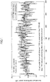
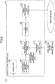
- Fig. 1 shows an example of variation of the interference amount for each TTI.
- the horizontal axis indicates TTI, and the vertical axis indicates normalized interference power
- Fig. 1 shows Round Robin (RR) scheduling and Proportional Fairness (PF) scheduling.
- RR Round Robin
- PF Proportional Fairness
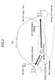
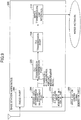
- each base station measures the uplink interference amount, and reports the interference amount to neighboring cells via a network using OLI.
- the base station receiving OLI from a neighboring cell causes a mobile station to decrease transmission power when it is determined that the interference amount exerted on the neighboring cell is large. Accordingly, the other-cell interference amount can be controlled, that is, can be decreased, for example, so that throughput characteristics of the whole system and user throughput characteristics can be improved.
- E-UTRA different from HSUPA, time/frequency scheduling is applied as mentioned above.
- the other-cell interference amount varies for each TTI, and mobile stations which are assigned transmission vary for each RB. Therefore, the interference amount largely varies.
- TTI is 1.0msec.
- OLI needs to be reported 1000 times per one second.
- the number of RBs is 50, for example, in the case of a bandwidth of 10 MHz.
- 50 pieces of OLI information on RB need to be reported in this case. This causes large load not only for the network, but also for the base station apparatus which performs transmit and receive processing of OLI.
- OLI is reported based on an average interference amount every one second, instead of every TTI in the time axis direction.
- OLI is reported based on an interference amount averaged in the whole band, instead of every RB.
- an object of the present invention is to provide a base station apparatus and a communication control method which can effectively control the other-cell interference amount based on a realistic control signal amount of the overload indicator by decreasing the control signal amount of the overload indicator while maintaining resolution of control in the time axis direction and the frequency axis direction.
- one aspect of the present invention relates to a base station apparatus for performing time and frequency scheduling in uplink packet access, including:
- Another aspect of the present invention relates to a communication control method in a base station apparatus for performing time and frequency scheduling in uplink packet access, including:
- a base station apparatus and a communication control method which can effectively control the other-cell interference amount based on a realistic control signal amount of the overload indicator can be realized by decreasing the control signal amount of the overload indicator while maintaining resolution of control in the time axis direction and the frequency axis direction.
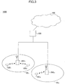
- a radio communication system including the mobile station and the base station apparatus of an embodiment of the present invention is described with reference to Fig. 3 .
- the radio communication system 1000 is a system to which E-UTRA is applied, for example.
- the radio communication system 1000 includes a base station apparatus (eNB: eNode B) 200 (200 1 , 200 2 .... 200 l , l is an integer of l>0) and a plurality of mobile stations 100 n (100 1 , 100 2 , 100 3 , ⁇ 100 n , n is an integer and n>0).
- the base station apparatus 200 is connected to an upper station, that is, an access gateway apparatus 300, for example, and the access gateway apparatus 300 is connected to a core network 400.
- the mobile station 100 n is communicating with the base station apparatus 200 by E-UTRA in a cell 50 (50 1 , 50 2 ). In the present embodiment, two cells are shown, but, more than two cells can be applied.
- the mobile stations (100 1 , 100 2 , 100 3 , ⁇ 100 n ) have the same configurations, functions and states, a mobile station 100 n is described unless otherwise mentioned.
- the entity which communicates with the base station apparatus by radio is the mobile station, it may be a user apparatus (UE: User Equipment) including a mobile terminal and a fixed terminal more generally.
- UE User Equipment
- the radio communication system 1000 uses OFDM (orthogonal frequency division multiplexing) in the downlink, and uses SC-FDMA (single carrier - frequency division multiple access) in the uplink.
- OFDM is a multi-carrier transmission scheme in which a frequency band is divided into a plurality of narrow frequency bands (subcarriers) so that transmission is performed by mapping data on each subcarrier.
- SC-FDMA is a single carrier transmission scheme that can decrease interference among terminals by dividing a frequency band for each terminal and by using different frequency bands with each other by a plurality of terminals.
- the physical downlink shared channel (PDSCH) shared by each mobile station 100 n and the physical downlink control channel (PDCCH) are used.
- the physical downlink control channel is also called a downlink L1/L2 control channel.
- User data that is, a normal data signal is transmitted by the physical downlink shared channel.
- the physical downlink control channel transmits downlink (DL) scheduling information, acknowledgment information (ACK/NACK), uplink (UL) scheduling grant, overload indicator, transmission power control command and the like.
- the DL scheduling information includes, for example, ID of a user performing communication using the physical downlink shared channel, information of transport format of the user data, that is, information related to data size, modulation scheme and HARQ, and includes assignment information of downlink resource blocks, and the like.
- the UL scheduling grant includes, for example, ID of a user performing communication using the physical uplink shared channel, information of transport format of the user data, that is, information related to data size and modulation scheme, and includes assignment information of the uplink resource blocks, transmission power control command, and the like.
- the uplink resource block corresponds to frequency resources, and is also called a resource unit.
- the acknowledgement information (ACK/NACK) is acknowledgement information on the uplink shared channel.
- the physical uplink shared channel (PUSCH) shared by each mobile station 100 n and the physical uplink control channel are used.
- the physical uplink shared channel transmits user data, that is, the normal data signal.
- the physical uplink control channel transmits downlink quality information (CQI: Channel Quality Indicator) used for scheduling processing for the physical downlink shared channel and for the adaptive modulation and coding scheme (AMC), and transmits acknowledgment information of the physical downlink shared channel.
- CQI Channel Quality Indicator
- AMC adaptive modulation and coding scheme
- the contents of the acknowledgment information are represented as either one of Acknowledgement (ACK) indicating that a transmission signal has been properly received or Negative Acknowledgement (NACK) indicating that the signal has not been properly received.
- ACK Acknowledgement
- NACK Negative Acknowledgement
- the physical uplink control channel may transmit a scheduling request requesting resource assignment of the uplink shared channel, resource request in persistent scheduling, and the like.
- the resource assignment of the uplink shared channel means that the base station apparatus reports, using the physical downlink control channel of a subframe, information to the mobile station indicating that the mobile station is permitted to perform communication using the uplink shared channel in a following subframe.
- the mobile station 100 n communicates with an optimum base station apparatus.
- mobile stations 100 1 and 100 2 communicates with a base station apparatus 200 1
- a mobile station 100 3 communicates with a base station apparatus 200 2 .
- uplink transmission by the mobile stations 100 1 and 100 2 becomes interference for the base station apparatus 200 2 which forms a neighboring cell.
- the other-cell interference largely varies since the mobile station changes every TTI and every RB due to the uplink packet scheduling.
- the base station apparatus 200 2 measures an uplink interference amount, and sends an overload indicator (OLI) to the base station apparatus 200 1 via a network for reporting state of the measured uplink interference amount.
- the base station apparatus 200 1 that receives OLI from the base station apparatus 200 2 determines transmission power for controlling transmission power of a communicating mobile station.
- the base station apparatus 200 2 determines that an uplink interference amount from a mobile station (mobile station 100 1 and/or 100 2 , for example) residing in a cell covered by a base station apparatus (base station apparatus 200 1 , for example) which covers a neighboring cell other than the base station apparatus 200 2 is large, the base station apparatus 200 2 transmits OLI to the base station apparatus 200 1 in order to decrease transmission power of the mobile station 100 1 and/or 100 2 .
- the base station apparatus 200 1 determines that the mobile stations 100 1 and 100 2 residing in the area covered by the base station apparatus 200 1 exerts large interference on the base station apparatus 200 2 other than the base station apparatus 200 1 , so that the base station apparatus 200 1 causes the mobile station 100 1 and/or 100 2 . to decrease the transmission power.
- the base station apparatus 200 of an embodiment of the present invention is described with reference to Fig. 4 .
- the base station apparatus 200 of the present embodiment includes a radio part 202, an other-cell interference amount measurement part 204 as an interference amount measurement part, an OLI transmission determination part 206 as an interference amount determination part, an OLI transmission part 208 as an overload indicator reporting part, and a wired transmission line interface 210.
- the wired transmission line interface is connected to a wired network.
- the base station apparatus 200 When the base station apparatus 200 receives an uplink signal, which is the physical uplink shared channel, for example, the base station apparatus 200 performs reception processing in the radio part 202 so as to obtain a baseband signal.
- the received baseband signal is input to the other-cell interference amount measurement part 204, so that the other-cell interference amount measurement part 204 measures the other-cell interference amount.
- an uplink signal is received from a mobile station apparatus residing in an area covered by a base station apparatus other than the own base station apparatus.
- the measurement of the interference amount is performed for each interference amount measurement period and for each interference amount measurement unit frequency block, that is, the measurement of the interference amount is performed every interference measurement unit. Typically, the measurement is performed every TTI and every RB.
- the measurement may be performed every multiple TTIs and/or every multiple RBs in consideration of a control signal amount and a processing load in the base station and the like.
- the other-cell interference amount measurement part 204 inputs the measured other-cell interference amount into the OLI transmission determination part 206.
- the OLI transmission determination part 206 determines whether to send the OLI to a neighboring cell based on measurement result of the other-cell interference amount. For example, based on a reference value which is set beforehand, the OLI transmission determination part 206 determines to report OLI only when the other-cell interference amount in each interference amount measurement unit is equal to or greater than the reference value.
- the reference value is determined based on whether it is necessary, for a base station apparatus in a neighboring cell, to cause a subject interference station (for example, a residing mobile station) to decrease transmission power. For example, when the other-cell interference amount in each interference amount measurement unit is equal to or greater than the reference value, OLI indicating decreasing transmission power is transmitted to the neighboring cell.
- the neighboring cell performs control of transmission power based on the received OLI. In this case, the neighboring cell performs control to cause the residing mobile station to lower transmission power. Therefore, when other-cell interference amount in each interference amount measurement unit does not satisfy the reference value, it is determined that the base station apparatus of the neighboring cell does not need to consider OLI when determining transmission power of the mobile station, so that OLI is not transmitted.
- the OLI transmission determination part 206 determines to report OLI
- the OLI transmission part 208 transmits OLI to the neighboring cell.
- OLI is reported to another base station apparatus via the wired transmission line interface 210 and the wired network.
- the other base station apparatus controls transmission power of the subject interference station based on the overload indicator transmitted from the neighboring cell.
- the base station apparatus 200 2 need not report OLI when it is determined that the base station apparatus 200 1 does not need to consider OLI for determining transmission power of the residing mobile station. Therefore, transmission load of control signals in the network due to OLI, and load for OLI transmit and receive processing can be largely decreased in the base station apparatus.
- an optimum value as a system parameter is set beforehand as the reference value used for determining whether to report OLI.
- the base station apparatus receives an uplink signal from a mobile station apparatus residing in an area covered by a base station apparatus other than the own base station apparatus.
- the other-cell interference amount measurement part 204 measures an other-cell interference amount based on the uplink signal (step S502).
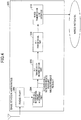
- the OLI transmission determination part 206 determines whether the other-cell interference amount measured in step S502 satisfies a predetermined condition (step S504). For example, it is determined whether the other-cell interference amount is equal to or greater than a predetermined reference value which is set beforehand.
- step S504 When the other-cell interference amount satisfies the predetermined reference value (step S504: Yes), that is, when the other-cell interference amount is equal to or greater than a predetermined reference value that is set beforehand, for example, the OLI transmission control part 206 determines to transmit an overload indicator to a neighboring cell, and the OLI transmit part 208 transmits the overload indicator to the neighboring cell (step S506). After that, the process returns to stepS502.
- step S504:NO when the other-cell interference amount does not satisfy the predetermined reference value (step S504:NO), that is, when the other-cell interference amount is less than a predetermined reference value that is set beforehand, for example, the process returns to step S502.
- the configuration of the radio communication system of the present embodiment is the same as the configuration of the radio communication system described with reference to Fig. 3 .
- the base station apparatus 200 of the present embodiment is described with reference to Fig. 6 .
- the base station apparatus 200 of the present embodiment includes a reference value control part 212 connected the OLI transmission determination part 206 in addition to components of the base station apparatus described with reference to Fig. 4 .
- the reference value control part 212 receives a control signal from an upper station, for example, from the access gateway apparatus 300.
- the upper station 300 generates a control signal based on a traffic state of the network and a state of the other-cell interference amount and the like, and transmits the generated control signal to each base station apparatus.
- the control signal transmitted by the upper station 300 is received by the base station apparatus 200, and is input into the reference value control part 212.
- the reference value control part 212 controls a reference value based on the input control signal.
- the configuration of the radio communication system of the present embodiment is similar to the configuration of the radio communication system described with reference to Fig. 3 .
- the base station apparatus 200 according to the present embodiment is described with reference to Fig. 7 .
- the base station apparatus 200 of the present embodiment includes a reference value determination part 214 connected the OLI transmission determination part 206 in addition to components of the base station apparatus described with reference to Fig. 4 .
- the reference value determination part 214 autonomously determines the reference value based on a traffic state of the network and a state of the other-cell interference amount and the like.
- the reference value determination part 214 may determine a reference number N such that OLI is reported only for the top N (N is an integer of N>0) RBs in the other-cell interference amount from the largest one among RBs (frequency blocks) in a TTI.
- N is an integer of N>0
- the OLI transmission determination part 206 determines to transmit OLI only for the top N RBs in the other-cell interference amount from the largest one among RBs in a TTI. Accordingly, OLI is transmitted to the base station apparatus 200 1 for only RBs which exert large effect, and OLI for other RBs is not reported. Therefore, it becomes possible to largely reduce network transmission load for transmitting control signals due to OLI, and largely reduce load for OLI transmit and receive processing in the base station apparatus 200.
- the reference value determination part 214 may set a reference value and a reference number N, such that, in each interference amount measurement unit, OLI is reported for only the top N (N is an integer of N>0) RBs in the other-cell interference amount among RBs in which the other-cell interference amount is equal to or greater than the reference value. Accordingly, when there are many interference amount measurement units in which the other-cell interference amount becomes equal to or greater than the reference value, the interference amount measurement units for which OLI is reported can be limited to the top reference number N. Therefore, it becomes possible to largely reduce network transmission load for transmitting control signals due to OLI, and reduce load for OLI transmit and receive processing in the base station apparatus 200.
- the configuration of the radio communication system of the present embodiment is similar to the configuration of the radio communication system described with reference to Fig. 3 .
- the base station apparatus 200 according to the present embodiment is described with reference to Fig. 8 .
- the base station apparatus 200 of the present embodiment includes an other-cell interference amount measurement unit control part 216 connected the other-cell interference amount measurement part 204 in addition to components of the base station apparatus described with reference to Fig. 4 .
- the other-cell interference amount measurement unit control part 216 changes time unit and/or frequency block unit for measuring the interference amount, that is, the other-cell interference amount measurement unit control part 216 changes the interference amount measurement unit (OLI reporting unit).
- An optimum value as a system parameter may be set beforehand as the interference amount measurement unit value.
- the configuration of the radio communication system of the present embodiment is similar to the configuration of the radio communication system described with reference to Fig. 3 .
- the base station apparatus 200 according to the present embodiment is described with reference to Fig. 9 .
- the base station apparatus 200 of the present embodiment is configured such that the other-cell interference amount measurement unit control part 216 receives a control signal from an upper station, that is, from the access gateway apparatus 300, for example, in the base station apparatus described with reference to Fig. 8 .
- the upper station 300 generates the control signal based on a traffic state of the network and a state of the other-cell interference amount, and transmits the generated control signal to each base station. Based on the control signal transmitted from the upper station 300, the other-cell interference amount measurement unit control part 216 controls the interference amount measurement unit. In addition, the other-cell interference amount measurement unit control part 216 may autonomously control the interference amount measurement unit based on the traffic state of the network and the state of the other-cell interference amount and the like.
Abstract
Description
- The present invention relates to a radio communication system. More particularly, the present invention relates to a base station apparatus and a communication control method.
- 3GPP that is a standardization group of the third generation mobile communication system is studying a communication scheme that becomes an evolved version of W-CDMA, HSDPA and HSUPA, that is, 3GPP is studying Evolved UTRA and UTRAN (Another name: Long Term Evolution or Super 3G, to be referred to as E-UTRA hereinafter) (refer to
non-patent document 1, for example). - Different from W-CDMA and the like, E-UTRA realizes all packet access including radio sections. Especially, in the uplink, although the component of the packet access is introduced in HSUPA which is an evolved version of W-CDMA, HSUPA uses circuit switching type communication based on dedicated channels. Uplink access schemes are largely different between E-UTRA and earlier W-CDMA or HSUPA.
- As main features, E-UTRA adopts all packet access, and adopts time/frequency packet scheduling. Thus, in each cell, mobile stations to which uplink radio resources are assigned are different for each TTI (Transmission Time Interval) and for each resource block (RB). As a result, the other-cell interference amount applied to neighboring cells due to uplink transmission in a cell largely varies every TTI and largely varies every RB.
-
Fig. 1 shows an example of variation of the interference amount for each TTI. InFig. 1 , the horizontal axis indicates TTI, and the vertical axis indicates normalized interference power, andFig. 1 shows Round Robin (RR) scheduling and Proportional Fairness (PF) scheduling. As a result, in both of the scheduling schemes, the uplink SINR (Signal-to-Interference plus Noise Power Ratio) largely varies, so that communication quality deteriorates. Therefore, how the variation of other-cell interference should be decreased is an issue. - As a method for decreasing the other-cell interference, a method using a control signal called Overload Indicator (OLI) is adopted in HSUPA and E-UTRA (refer to
non-patent document 2, for example). As shown inFig. 2 , each base station measures the uplink interference amount, and reports the interference amount to neighboring cells via a network using OLI. The base station receiving OLI from a neighboring cell causes a mobile station to decrease transmission power when it is determined that the interference amount exerted on the neighboring cell is large. Accordingly, the other-cell interference amount can be controlled, that is, can be decreased, for example, so that throughput characteristics of the whole system and user throughput characteristics can be improved. - [Non-patent document 1] 3GPP TR25.814 (V7.1.0), "Physical Layer Aspects for Evolved UTRA", Sept. 2006.
- [Non-patent document 2] 3GPP, TS 25.309, (V6.6.0), "FDD Enhanced Uplink .
- However, the above-mentioned background technique has the following problem.
- In E-UTRA, different from HSUPA, time/frequency scheduling is applied as mentioned above. Thus, the other-cell interference amount varies for each TTI, and mobile stations which are assigned transmission vary for each RB. Therefore, the interference amount largely varies. Thus, in order to effectively control the other-cell interference amount, it is necessary to report OLI for each TTI in the time axis direction, and for each RB in the frequency axis direction. In E-UTRA, TTI is 1.0msec. Thus, OLI needs to be reported 1000 times per one second. In addition, the number of RBs is 50, for example, in the case of a bandwidth of 10 MHz. Thus, 50 pieces of OLI information on RB need to be reported in this case. This causes large load not only for the network, but also for the base station apparatus which performs transmit and receive processing of OLI.
- Therefore, in actuality, a method for lowering resolution of control is being studied. In the method, for example, OLI is reported based on an average interference amount every one second, instead of every TTI in the time axis direction. In the frequency axis direction, for example, OLI is reported based on an interference amount averaged in the whole band, instead of every RB.
- However, in the control based on the average interference amount, there is a problem in that the other-cell interference amount cannot be effectively controlled in the E-UTRA uplink packet access in which interference amount largely varies every TTI and every RB.
- In view of the above-mentioned problem, an object of the present invention is to provide a base station apparatus and a communication control method which can effectively control the other-cell interference amount based on a realistic control signal amount of the overload indicator by decreasing the control signal amount of the overload indicator while maintaining resolution of control in the time axis direction and the frequency axis direction.
- In order to overcome the above problem, one aspect of the present invention relates to a base station apparatus for performing time and frequency scheduling in uplink packet access, including:
- an interference amount measurement part configured to measure an uplink interference amount for each interference amount measurement unit which comprises a predetermined period and a predetermined number of frequency blocks;
- an interference amount determination part configured to determine whether the uplink interference amount satisfies a predetermined condition; and
- an overload indicator reporting part configured to report an overload indicator to a neighboring cell when the predetermined condition is satisfied.
- Another aspect of the present invention relates to a communication control method in a base station apparatus for performing time and frequency scheduling in uplink packet access, including:
- an interference amount measurement step of measuring an uplink interference amount for each interference amount measurement unit which comprises a predetermined period and a predetermined number of frequency blocks;
- an interference amount determination step of determining whether the uplink interference amount satisfies a predetermined condition; and
- an overload indicator reporting step of reporting an overload indicator to a neighboring cell when the predetermined condition is satisfied.
- According to an embodiment of the present invention, a base station apparatus and a communication control method which can effectively control the other-cell interference amount based on a realistic control signal amount of the overload indicator can be realized by decreasing the control signal amount of the overload indicator while maintaining resolution of control in the time axis direction and the frequency axis direction.
-
-
Fig. 1 is an explanatory diagram showing an example of variation of interference amount in each TTI; -
Fig. 2 is an explanatory diagram showing an example of transmission power control; -
Fig. 3 is an explanatory diagram showing a radio communication system of an embodiment of the present invention; -
Fig. 4 is a partial block diagram showing a base station apparatus of an embodiment of the present invention; -
Fig. 5 is a flow diagram showing operation of the base station apparatus of an embodiment of the present invention; -
Fig. 6 is a partial block diagram showing the base station apparatus of an embodiment of the present invention; -
Fig. 7 is a partial block diagram showing the base station apparatus of an embodiment of the present invention; -
Fig. 8 is a partial block diagram showing the base station apparatus of an embodiment of the present invention; and -
Fig. 9 is a partial block diagram showing the base station apparatus of an embodiment of the present invention. -
- 50 (501, 502) cell
- 100 (1001, 1002, 1003, ···100n) user apparatus
- 200 (2001, 2002 .... 200l) base station apparatus
- 202 radio part
- 204 other-cell interference measurement part
- 206 OLI transmission determination part
- 208 OLI transmission part
- 210 wired transmission line interface
- 212 reference value control part
- 214 reference value determination part
- 216 other-cell interference amount measurement unit
- control part
- 300 access gateway apparatus
- 400 core network
- 1000 radio communication system
- In the following, embodiments of the present invention are described with reference to figures. In all of the figures for explaining embodiments, the same reference symbols are used for parts having the same function, and repeated descriptions are not given.
- A radio communication system including the mobile station and the base station apparatus of an embodiment of the present invention is described with reference to
Fig. 3 . - The
radio communication system 1000 is a system to which E-UTRA is applied, for example. Theradio communication system 1000 includes a base station apparatus (eNB: eNode B) 200 (2001, 2002 .... 200l, l is an integer of l>0) and a plurality of mobile stations 100n (1001, 1002, 1003, ···100n, n is an integer and n>0). Thebase station apparatus 200 is connected to an upper station, that is, anaccess gateway apparatus 300, for example, and theaccess gateway apparatus 300 is connected to acore network 400. Themobile station 100n is communicating with thebase station apparatus 200 by E-UTRA in a cell 50 (501, 502). In the present embodiment, two cells are shown, but, more than two cells can be applied. - In the following, since the mobile stations (1001, 1002, 1003, ···100n) have the same configurations, functions and states, a
mobile station 100n is described unless otherwise mentioned. For the sake of convenience of explanation, although the entity which communicates with the base station apparatus by radio is the mobile station, it may be a user apparatus (UE: User Equipment) including a mobile terminal and a fixed terminal more generally. - As radio access schemes, the
radio communication system 1000 uses OFDM (orthogonal frequency division multiplexing) in the downlink, and uses SC-FDMA (single carrier - frequency division multiple access) in the uplink. OFDM is a multi-carrier transmission scheme in which a frequency band is divided into a plurality of narrow frequency bands (subcarriers) so that transmission is performed by mapping data on each subcarrier. SC-FDMA is a single carrier transmission scheme that can decrease interference among terminals by dividing a frequency band for each terminal and by using different frequency bands with each other by a plurality of terminals. - In the following, communication channels in the E-UTRA are described.
- In the downlink, the physical downlink shared channel (PDSCH) shared by each
mobile station 100n and the physical downlink control channel (PDCCH) are used. The physical downlink control channel is also called a downlink L1/L2 control channel. User data, that is, a normal data signal is transmitted by the physical downlink shared channel. Also, the physical downlink control channel transmits downlink (DL) scheduling information, acknowledgment information (ACK/NACK), uplink (UL) scheduling grant, overload indicator, transmission power control command and the like. - The DL scheduling information includes, for example, ID of a user performing communication using the physical downlink shared channel, information of transport format of the user data, that is, information related to data size, modulation scheme and HARQ, and includes assignment information of downlink resource blocks, and the like.
- The UL scheduling grant includes, for example, ID of a user performing communication using the physical uplink shared channel, information of transport format of the user data, that is, information related to data size and modulation scheme, and includes assignment information of the uplink resource blocks, transmission power control command, and the like. The uplink resource block corresponds to frequency resources, and is also called a resource unit.
- The acknowledgement information (ACK/NACK) is acknowledgement information on the uplink shared channel.
- In the uplink, the physical uplink shared channel (PUSCH) shared by each
mobile station 100n and the physical uplink control channel are used. The physical uplink shared channel transmits user data, that is, the normal data signal. In addition, the physical uplink control channel transmits downlink quality information (CQI: Channel Quality Indicator) used for scheduling processing for the physical downlink shared channel and for the adaptive modulation and coding scheme (AMC), and transmits acknowledgment information of the physical downlink shared channel. The contents of the acknowledgment information are represented as either one of Acknowledgement (ACK) indicating that a transmission signal has been properly received or Negative Acknowledgement (NACK) indicating that the signal has not been properly received. - In addition to the CQI and the acknowledgement information, the physical uplink control channel may transmit a scheduling request requesting resource assignment of the uplink shared channel, resource request in persistent scheduling, and the like. The resource assignment of the uplink shared channel means that the base station apparatus reports, using the physical downlink control channel of a subframe, information to the mobile station indicating that the mobile station is permitted to perform communication using the uplink shared channel in a following subframe.
- The
mobile station 100n communicates with an optimum base station apparatus. In the example shown inFig. 3 ,mobile stations base station apparatus 2001, and amobile station 1003 communicates with abase station apparatus 2002. In this case, uplink transmission by themobile stations base station apparatus 2002 which forms a neighboring cell. As described before, the other-cell interference largely varies since the mobile station changes every TTI and every RB due to the uplink packet scheduling. - Thus, the
base station apparatus 2002 measures an uplink interference amount, and sends an overload indicator (OLI) to thebase station apparatus 2001 via a network for reporting state of the measured uplink interference amount. Thebase station apparatus 2001 that receives OLI from thebase station apparatus 2002 determines transmission power for controlling transmission power of a communicating mobile station. That is, when thebase station apparatus 2002 determines that an uplink interference amount from a mobile station (mobile station 1001 and/or 1002, for example) residing in a cell covered by a base station apparatus (base station apparatus 2001, for example) which covers a neighboring cell other than thebase station apparatus 2002 is large, thebase station apparatus 2002 transmits OLI to thebase station apparatus 2001 in order to decrease transmission power of themobile station 1001 and/or 1002. - Based on the OLI, the
base station apparatus 2001 determines that themobile stations base station apparatus 2001 exerts large interference on thebase station apparatus 2002 other than thebase station apparatus 2001, so that thebase station apparatus 2001 causes themobile station 1001 and/or 1002. to decrease the transmission power. - The
base station apparatus 200 of an embodiment of the present invention is described with reference toFig. 4 . - The
base station apparatus 200 of the present embodiment includes aradio part 202, an other-cell interferenceamount measurement part 204 as an interference amount measurement part, an OLItransmission determination part 206 as an interference amount determination part, anOLI transmission part 208 as an overload indicator reporting part, and a wiredtransmission line interface 210. The wired transmission line interface is connected to a wired network. - When the
base station apparatus 200 receives an uplink signal, which is the physical uplink shared channel, for example, thebase station apparatus 200 performs reception processing in theradio part 202 so as to obtain a baseband signal. The received baseband signal is input to the other-cell interferenceamount measurement part 204, so that the other-cell interferenceamount measurement part 204 measures the other-cell interference amount. For example, an uplink signal is received from a mobile station apparatus residing in an area covered by a base station apparatus other than the own base station apparatus. The measurement of the interference amount is performed for each interference amount measurement period and for each interference amount measurement unit frequency block, that is, the measurement of the interference amount is performed every interference measurement unit. Typically, the measurement is performed every TTI and every RB. But, the measurement may be performed every multiple TTIs and/or every multiple RBs in consideration of a control signal amount and a processing load in the base station and the like. The other-cell interferenceamount measurement part 204 inputs the measured other-cell interference amount into the OLItransmission determination part 206. - The OLI
transmission determination part 206 determines whether to send the OLI to a neighboring cell based on measurement result of the other-cell interference amount. For example, based on a reference value which is set beforehand, the OLItransmission determination part 206 determines to report OLI only when the other-cell interference amount in each interference amount measurement unit is equal to or greater than the reference value. The reference value is determined based on whether it is necessary, for a base station apparatus in a neighboring cell, to cause a subject interference station (for example, a residing mobile station) to decrease transmission power. For example, when the other-cell interference amount in each interference amount measurement unit is equal to or greater than the reference value, OLI indicating decreasing transmission power is transmitted to the neighboring cell. The neighboring cell performs control of transmission power based on the received OLI. In this case, the neighboring cell performs control to cause the residing mobile station to lower transmission power. Therefore, when other-cell interference amount in each interference amount measurement unit does not satisfy the reference value, it is determined that the base station apparatus of the neighboring cell does not need to consider OLI when determining transmission power of the mobile station, so that OLI is not transmitted. - When the OLI
transmission determination part 206 determines to report OLI, theOLI transmission part 208 transmits OLI to the neighboring cell. As a result, OLI is reported to another base station apparatus via the wiredtransmission line interface 210 and the wired network. The other base station apparatus controls transmission power of the subject interference station based on the overload indicator transmitted from the neighboring cell. - Accordingly, the
base station apparatus 2002 need not report OLI when it is determined that thebase station apparatus 2001 does not need to consider OLI for determining transmission power of the residing mobile station. Therefore, transmission load of control signals in the network due to OLI, and load for OLI transmit and receive processing can be largely decreased in the base station apparatus. - Even though the system is configured as mentioned above, OLI is reported for an interference amount measurement unit that exerts large effect in which the other-cell interference amount in each interference amount measurement unit is equal to or greater than the reference value. Thus, the effect for control the other-cell interference amount can be sufficiently obtained.
- In the present embodiment, an optimum value as a system parameter is set beforehand as the reference value used for determining whether to report OLI.
- Next, operation of the base station apparatus in the radio communication system in the present embodiment is described with reference to
Fig. 5 . - The base station apparatus receives an uplink signal from a mobile station apparatus residing in an area covered by a base station apparatus other than the own base station apparatus.
- The other-cell interference
amount measurement part 204 measures an other-cell interference amount based on the uplink signal (step S502). - The OLI
transmission determination part 206 determines whether the other-cell interference amount measured in step S502 satisfies a predetermined condition (step S504). For example, it is determined whether the other-cell interference amount is equal to or greater than a predetermined reference value which is set beforehand. - When the other-cell interference amount satisfies the predetermined reference value (step S504: Yes), that is, when the other-cell interference amount is equal to or greater than a predetermined reference value that is set beforehand, for example, the OLI
transmission control part 206 determines to transmit an overload indicator to a neighboring cell, and the OLI transmitpart 208 transmits the overload indicator to the neighboring cell (step S506). After that, the process returns to stepS502. - On the other hand, when the other-cell interference amount does not satisfy the predetermined reference value (step S504:NO), that is, when the other-cell interference amount is less than a predetermined reference value that is set beforehand, for example, the process returns to step S502.
- Next, a radio communication system of another embodiment of the present invention is described.
- The configuration of the radio communication system of the present embodiment is the same as the configuration of the radio communication system described with reference to
Fig. 3 . - The
base station apparatus 200 of the present embodiment is described with reference toFig. 6 . - The
base station apparatus 200 of the present embodiment includes a referencevalue control part 212 connected the OLItransmission determination part 206 in addition to components of the base station apparatus described with reference toFig. 4 . The referencevalue control part 212 receives a control signal from an upper station, for example, from theaccess gateway apparatus 300. - The
upper station 300 generates a control signal based on a traffic state of the network and a state of the other-cell interference amount and the like, and transmits the generated control signal to each base station apparatus. The control signal transmitted by theupper station 300 is received by thebase station apparatus 200, and is input into the referencevalue control part 212. The referencevalue control part 212 controls a reference value based on the input control signal. By performing such processes, the reference value used for determining whether to report OLI can be flexibly changed according to the traffic state of the network and the state of the other-cell interference amount and the like. - Next, a radio communication system of another embodiment of the present invention is described.
- The configuration of the radio communication system of the present embodiment is similar to the configuration of the radio communication system described with reference to
Fig. 3 . - The
base station apparatus 200 according to the present embodiment is described with reference toFig. 7 . - The
base station apparatus 200 of the present embodiment includes a referencevalue determination part 214 connected the OLItransmission determination part 206 in addition to components of the base station apparatus described with reference toFig. 4 . The referencevalue determination part 214 autonomously determines the reference value based on a traffic state of the network and a state of the other-cell interference amount and the like. - Based on the measurement result of the other-cell interference amount measured for each interference amount measurement unit, the reference
value determination part 214 may determine a reference number N such that OLI is reported only for the top N (N is an integer of N>0) RBs in the other-cell interference amount from the largest one among RBs (frequency blocks) in a TTI. In this case, the OLItransmission determination part 206 determines to transmit OLI only for the top N RBs in the other-cell interference amount from the largest one among RBs in a TTI. Accordingly, OLI is transmitted to thebase station apparatus 2001 for only RBs which exert large effect, and OLI for other RBs is not reported. Therefore, it becomes possible to largely reduce network transmission load for transmitting control signals due to OLI, and largely reduce load for OLI transmit and receive processing in thebase station apparatus 200. - Even though the system is configured as mentioned above, OLI is reported for an interference amount measurement unit that exerts large effect in which the other-cell interference amount in each interference amount measurement unit is large. Thus, the effect for controlling the other-cell interference amount can be sufficiently obtained.
- In addition, the reference
value determination part 214 may set a reference value and a reference number N, such that, in each interference amount measurement unit, OLI is reported for only the top N (N is an integer of N>0) RBs in the other-cell interference amount among RBs in which the other-cell interference amount is equal to or greater than the reference value. Accordingly, when there are many interference amount measurement units in which the other-cell interference amount becomes equal to or greater than the reference value, the interference amount measurement units for which OLI is reported can be limited to the top reference number N. Therefore, it becomes possible to largely reduce network transmission load for transmitting control signals due to OLI, and reduce load for OLI transmit and receive processing in thebase station apparatus 200. - Even though the system is configured as mentioned above, OLI is reported for an interference amount measurement unit that exerts large effect in which the other-cell interference amount in each interference amount measurement unit is equal to or greater than the reference value. Thus, the effect for controlling the other-cell interference amount can be sufficiently obtained.
- Next, a radio communication system of another embodiment of the present invention is described.
- The configuration of the radio communication system of the present embodiment is similar to the configuration of the radio communication system described with reference to
Fig. 3 . - The
base station apparatus 200 according to the present embodiment is described with reference toFig. 8 . - The
base station apparatus 200 of the present embodiment includes an other-cell interference amount measurementunit control part 216 connected the other-cell interferenceamount measurement part 204 in addition to components of the base station apparatus described with reference toFig. 4 . - The other-cell interference amount measurement
unit control part 216 changes time unit and/or frequency block unit for measuring the interference amount, that is, the other-cell interference amount measurementunit control part 216 changes the interference amount measurement unit (OLI reporting unit). An optimum value as a system parameter may be set beforehand as the interference amount measurement unit value. - Next, a radio communication system of another embodiment of the present invention is described.
- The configuration of the radio communication system of the present embodiment is similar to the configuration of the radio communication system described with reference to
Fig. 3 . - The
base station apparatus 200 according to the present embodiment is described with reference toFig. 9 . - The
base station apparatus 200 of the present embodiment is configured such that the other-cell interference amount measurementunit control part 216 receives a control signal from an upper station, that is, from theaccess gateway apparatus 300, for example, in the base station apparatus described with reference toFig. 8 . - The
upper station 300 generates the control signal based on a traffic state of the network and a state of the other-cell interference amount, and transmits the generated control signal to each base station. Based on the control signal transmitted from theupper station 300, the other-cell interference amount measurementunit control part 216 controls the interference amount measurement unit. In addition, the other-cell interference amount measurementunit control part 216 may autonomously control the interference amount measurement unit based on the traffic state of the network and the state of the other-cell interference amount and the like. - For the sake of convenience of explanation, the present invention is described by using some embodiments. But, classification into each embodiment is not essential in the present invention, and equal to or more than two embodiments may be used as necessary. While specific numerical value examples are used to facilitate understanding of the present invention, such numerical values are merely examples, so that any appropriate value may be used unless specified otherwise.
- As described above, while the present invention is described with reference to specific embodiments, the respective embodiments are merely exemplary, so that a skilled person will understand variations, modifications, alternatives, and replacements. For convenience of explanation, while the apparatus according to the embodiments of the present invention is explained using functional block diagrams, such an apparatus as described above may be implemented in hardware, software, or a combination thereof. The present invention is not limited to the above embodiments, so that variations, modifications, alternatives, and replacements are included in the present invention without departing from the spirit of the present invention.
- The present international application claims priority based on Japanese patent application No.
2007-126036 2007-126036 - The present application also includes the following numbered clauses:
- 1. A base station apparatus for performing time and frequency scheduling in uplink packet access, comprising:
- an interference amount measurement part configured to measure an uplink interference amount for each interference amount measurement unit which comprises a predetermined period and a predetermined number of frequency blocks;
- an interference amount determination part configured to determine whether the uplink interference amount satisfies a predetermined condition; and
- an overload indicator reporting part configured to report an overload indicator to a neighboring cell when the predetermined condition is satisfied.
- 2. The base station apparatus as claimed in
clause 1,
wherein the interference amount determination part determines that the predetermined condition is satisfied when the interference amount measured for each interference amount measurement unit is equal to or greater than a predetermined reference value, and
the predetermined reference value is any one of a value set beforehand as a system parameter, a value set by a control signal sent from an upper apparatus, and a value autonomously controlled by the base station apparatus. - 3. The base station apparatus as claimed in
clause 1,
wherein the interference amount determination part determines that the predetermined condition is satisfied for the top predetermined reference number N of interference amount measurement units in the interference amount, from the largest interference amount, measured in each interference amount measurement unit, and
the predetermined reference number is any one of a value set beforehand as a system parameter, a value set by a control signal sent from an upper apparatus, and a value autonomously controlled by the base station apparatus. - 4. The base station apparatus as claimed in
clause 1,
wherein the interference amount determination part determines that the predetermined condition is satisfied for the top predetermined reference number N of interference amount measurement units in the interference amount from the largest interference amount, in which the interference amount measured in each of the interference amount measurement units is equal to or greater than a predetermined reference value, and
each of the predetermined value and the predetermined reference number is any one of a value set beforehand as a system parameter, a value set by a control signal sent from an upper apparatus, and a value autonomously controlled by the base station apparatus. - 5. The base station apparatus as claimed in
clause 1,
wherein the interference amount measurement unit is set by any one of a system parameter set beforehand, a control signal sent from an upper apparatus, and the base station apparatus. - 6. The base station apparatus as claimed in
clause 1, comprising:
a transmission power control part configured to control transmission power of a subject interference station based on an overload indicator sent from a neighboring cell. - 7. A communication control method in a base station apparatus for performing time and frequency scheduling in uplink packet access, comprising:
- an interference amount measurement step of measuring an uplink interference amount for each interference amount measurement unit which comprises a predetermined period and a predetermined number of frequency blocks;
- an interference amount determination step of determining whether the uplink interference amount satisfies a predetermined condition; and
- an overload indicator reporting step of reporting an overload indicator to a neighboring cell when the predetermined condition is satisfied.
Claims (10)
- A base station apparatus (200) for performing time and frequency scheduling in uplink packet access, comprising:an interference amount measurement part (204) configured to measure an uplink interference amount for each interference amount measurement unit which comprises a predetermined period in a time domain and a predetermined number of frequency blocks in a timefrequency domain, each frequency block being a unit in the frequency domain for performing the time and frequency scheduling;an interference amount determination part (206) configured to determine a case of variation in the uplink interference; andan overload indicator reporting part (208) configured to report an indication indicating at least one information of an uplink interference per a frequency block, to a neighboring base station apparatus in a case of the variation in the uplink interference, through an interface between the base station apparatus (200) and the neighboring base station apparatus.
- The base station apparatus (200) as claimed in claim 1,
wherein the indication indicates whether an interference level per a frequency block is high or not. - The base station apparatus (200) as claimed in claim 1,
wherein the indication comprises at least one ofa frequency block indicating a high interference level, anda frequency block indicating a low interference level. - The base station apparatus (200) as claimed in claim 1, wherein
the indication indicates an uplink interference level experienced by a cell. - The base station apparatus (200) as claimed in claim 1,
further comprising a data reception part (202) configured to receive an uplink data via a physical uplink shared channel (PUSCH) . - A communication control method in a base station apparatus (200) for performing time and frequency scheduling in uplink packet access, comprising:an interference amount measurement step (S502) of measuring an uplink interference amount for each interference amount measurement unit which comprises a predetermined period in a time domain and a predetermined number of frequency blocks in a timefrequency domain, each frequency block being a unit in the frequency domain for performing the time and frequency scheduling;an interference amount determination step (S504) of determining a case of variation in the uplink interference; andan overload indicator reporting step (S506) of reporting an indication indicating at least one information of an uplink interference per a frequency block, to a neighboring base station apparatus in a case of the variation in the uplink interference, through an interface between the base station apparatus (200) and the neighboring base station apparatus.
- The communication control method as claimed in claim 6,
wherein the indication indicates whether an interference level per a frequency block is high or not. - The communication control method as claimed in claim 6,
wherein the indication comprises at least one ofa frequency block indicating a high interference level, anda frequency block indicating a low interference level. - The communication control method as claimed in claim 1, wherein
the indication indicates an uplink interference level experienced by a cell. - The communication control method as claimed in claim 1,
further comprising a data reception step of receiving an uplink data via a physical uplink shared channel (PUSCH).
Applications Claiming Priority (3)
| Application Number | Priority Date | Filing Date | Title |
|---|---|---|---|
| JP2007126036A JP4848309B2 (en) | 2007-05-10 | 2007-05-10 | Base station apparatus and communication control method |
| PCT/JP2008/058094 WO2008139896A1 (en) | 2007-05-10 | 2008-04-25 | Base station device and communication control method |
| EP08740883.7A EP2150068B1 (en) | 2007-05-10 | 2008-04-25 | Base station device and communication control method |
Related Parent Applications (1)
| Application Number | Title | Priority Date | Filing Date |
|---|---|---|---|
| EP08740883.7A Division EP2150068B1 (en) | 2007-05-10 | 2008-04-25 | Base station device and communication control method |
Publications (2)
| Publication Number | Publication Date |
|---|---|
| EP3379885A1 true EP3379885A1 (en) | 2018-09-26 |
| EP3379885B1 EP3379885B1 (en) | 2020-05-13 |
Family
ID=40002112
Family Applications (2)
| Application Number | Title | Priority Date | Filing Date |
|---|---|---|---|
| EP18170941.1A Active EP3379885B1 (en) | 2007-05-10 | 2008-04-25 | Base station apparatus and communication control method |
| EP08740883.7A Active EP2150068B1 (en) | 2007-05-10 | 2008-04-25 | Base station device and communication control method |
Family Applications After (1)
| Application Number | Title | Priority Date | Filing Date |
|---|---|---|---|
| EP08740883.7A Active EP2150068B1 (en) | 2007-05-10 | 2008-04-25 | Base station device and communication control method |
Country Status (6)
| Country | Link |
|---|---|
| US (4) | US8451792B2 (en) |
| EP (2) | EP3379885B1 (en) |
| JP (1) | JP4848309B2 (en) |
| KR (1) | KR101447307B1 (en) |
| CN (2) | CN103476127B (en) |
| WO (1) | WO2008139896A1 (en) |
Families Citing this family (28)
| Publication number | Priority date | Publication date | Assignee | Title |
|---|---|---|---|---|
| US6807405B1 (en) | 1999-04-28 | 2004-10-19 | Isco International, Inc. | Method and a device for maintaining the performance quality of a code-division multiple access system in the presence of narrow band interference |
| JP4848309B2 (en) | 2007-05-10 | 2011-12-28 | 株式会社エヌ・ティ・ティ・ドコモ | Base station apparatus and communication control method |
| US8385483B2 (en) | 2008-11-11 | 2013-02-26 | Isco International, Llc | Self-adaptive digital RF bandpass and bandstop filter architecture |
| JP5293199B2 (en) * | 2009-01-08 | 2013-09-18 | 富士通株式会社 | Wireless communication device, control device, mobile communication system, and wireless communication method |
| JP5747285B2 (en) * | 2009-02-09 | 2015-07-15 | オプティス セルラー テクノロジー, エルエルシーOptis Cellular Technology,LLC | Method and apparatus in a wireless communication system |
| CN101835199A (en) * | 2009-03-10 | 2010-09-15 | 中兴通讯股份有限公司 | Triggering method and system of overload indicator report |
| US20110143675A1 (en) * | 2009-06-09 | 2011-06-16 | Qualcomm Incorporated | Method and apparatus for facilitating radio link monitoring and recovery |
| US8666318B2 (en) | 2009-06-24 | 2014-03-04 | Motorola Mobility Llc | Method and apparatus for managing cellular uplink transmissions |
| EP2465318A4 (en) * | 2009-08-14 | 2016-11-02 | Nokia Technologies Oy | Method and apparatus for managing interference handling overhead |
| CN101998642B (en) * | 2009-08-19 | 2014-08-20 | 株式会社Ntt都科摩 | Inter-cell interference coordination method and station |
| US20110070919A1 (en) * | 2009-09-18 | 2011-03-24 | Toshihiko Komine | Transmission power control apparatus, transmission power control method, and computer-readable storage medium storing transmission power control program |
| JP4621798B1 (en) | 2009-11-09 | 2011-01-26 | 京セラ株式会社 | Radio base station and communication control method |
| WO2011055841A1 (en) * | 2009-11-09 | 2011-05-12 | 京セラ株式会社 | Radio base station and communication control method |
| KR101727016B1 (en) | 2010-08-10 | 2017-04-14 | 삼성전자주식회사 | System and method for aligning interference in uplink |
| WO2012019366A1 (en) * | 2010-08-13 | 2012-02-16 | 富士通株式会社 | Base station on the basis of orthogonal frequency division multiplexing scheme and interference coordination method thereof |
| KR20120034902A (en) * | 2010-10-04 | 2012-04-13 | 삼성전자주식회사 | Communication method of macro base station, macro terminal, micro base station and micro terminal for interference control in hierarchical cellular network |
| JP2012231267A (en) * | 2011-04-25 | 2012-11-22 | Kyocera Corp | Radio base station and communication control method |
| KR20130085480A (en) * | 2011-12-07 | 2013-07-30 | 한국전자통신연구원 | Data communication apparatus and method thereof, and data communication system with the said apparatus and method thereof |
| US9319916B2 (en) | 2013-03-15 | 2016-04-19 | Isco International, Llc | Method and appartus for signal interference processing |
| CN104254121B (en) | 2013-06-28 | 2018-05-29 | 电信科学技术研究院 | A kind of PUSCH Poewr control methods and device |
| WO2015087527A1 (en) | 2013-12-09 | 2015-06-18 | 日本電気株式会社 | Wireless base station, wireless communication system, node, control method, and program |
| US9775116B2 (en) | 2014-05-05 | 2017-09-26 | Isco International, Llc | Method and apparatus for increasing performance of communication links of cooperative communication nodes |
| WO2016178778A1 (en) | 2015-05-04 | 2016-11-10 | Isco International, Llc | Method and apparatus for increasing performance of communication paths for communication nodes |
| WO2017210056A1 (en) | 2016-06-01 | 2017-12-07 | Isco International, Llc | Method and apparatus for performing signal conditioning to mitigate interference detected in a communication system |
| US10298279B2 (en) | 2017-04-05 | 2019-05-21 | Isco International, Llc | Method and apparatus for increasing performance of communication paths for communication nodes |
| US10812121B2 (en) | 2017-08-09 | 2020-10-20 | Isco International, Llc | Method and apparatus for detecting and analyzing passive intermodulation interference in a communication system |
| US10284313B2 (en) | 2017-08-09 | 2019-05-07 | Isco International, Llc | Method and apparatus for monitoring, detecting, testing, diagnosing and/or mitigating interference in a communication system |
| CN111083790B (en) * | 2018-10-19 | 2022-09-09 | 成都鼎桥通信技术有限公司 | Scheduling control method and device |
Citations (5)
| Publication number | Priority date | Publication date | Assignee | Title |
|---|---|---|---|---|
| US20020015393A1 (en) * | 2000-07-27 | 2002-02-07 | Interdigital Technology Corporation | Adaptive uplink/downlink timeslot assignment in a hybrid wireless time division multiple access/code division multiple access communication system |
| US20020102985A1 (en) * | 2001-01-31 | 2002-08-01 | Tantivy Communications, Inc. | Queuing far/far service requests in wireless network |
| EP1453341A2 (en) * | 2003-02-25 | 2004-09-01 | NTT DoCoMo, Inc. | Radio packet communication system, method, base station and mobile station |
| WO2006114873A1 (en) * | 2005-04-20 | 2006-11-02 | Mitsubishi Denki Kabushiki Kaisha | Communication quality determining method, mobile station, base station, and communication system |
| US20070036067A1 (en) * | 2005-08-12 | 2007-02-15 | Interdigital Technology Corporation | Method and apparatus for sending downlink control information in an orthogonal frequency division multiple access system |
Family Cites Families (15)
| Publication number | Priority date | Publication date | Assignee | Title |
|---|---|---|---|---|
| US6445917B1 (en) * | 1999-05-19 | 2002-09-03 | Telefonaktiebolaget Lm Ericsson (Publ) | Mobile station measurements with event-based reporting |
| CN100456758C (en) * | 2000-12-15 | 2009-01-28 | 昂达博思公司 | Multi-carrier communications with group-based subcarrier allocation |
| US6947748B2 (en) * | 2000-12-15 | 2005-09-20 | Adaptix, Inc. | OFDMA with adaptive subcarrier-cluster configuration and selective loading |
| JP3844968B2 (en) * | 2001-02-01 | 2006-11-15 | 株式会社エヌ・ティ・ティ・ドコモ | Call admission control apparatus and method |
| KR100837351B1 (en) * | 2002-04-06 | 2008-06-12 | 엘지전자 주식회사 | Update method for radio link parameter of mobile communication system |
| ATE347783T1 (en) * | 2002-06-28 | 2006-12-15 | Interdigital Tech Corp | INTERFERENCE BASED ESCAPE MECHANISMS IN THIRD GENERATION WIRELESS SYSTEMS |
| JP2004207840A (en) * | 2002-12-24 | 2004-07-22 | Nec Corp | Method of managing radio resource, managing apparatus used therefor, base station and terminal |
| JP4306275B2 (en) * | 2003-02-19 | 2009-07-29 | 日本電気株式会社 | Mobile communication system, radio base station controller, and transmission / reception power control method used therefor |
| US7742444B2 (en) * | 2005-03-15 | 2010-06-22 | Qualcomm Incorporated | Multiple other sector information combining for power control in a wireless communication system |
| US8050222B2 (en) * | 2005-03-28 | 2011-11-01 | Sony Corporation | Mobile communications system, handover controlling method, radio network controller, and mobile terminal |
| KR100895183B1 (en) * | 2006-02-03 | 2009-04-24 | 삼성전자주식회사 | Transmitting/receiving method and apparatus canceling other cell interference in wireless communication systems |
| EP1838116A1 (en) * | 2006-03-22 | 2007-09-26 | Matsushita Electric Industrial Co., Ltd. | Neigboring cell interference management in a SC-FDMA system |
| US9281917B2 (en) * | 2007-01-03 | 2016-03-08 | Nokia Technologies Oy | Shared control channel structure |
| US7773991B2 (en) * | 2007-04-02 | 2010-08-10 | Telefonaktiebolaget Lm Ericsson (Publ) | Reducing access latency while protecting against control signaling data processing overload |
| JP4848309B2 (en) | 2007-05-10 | 2011-12-28 | 株式会社エヌ・ティ・ティ・ドコモ | Base station apparatus and communication control method |
-
2007
- 2007-05-10 JP JP2007126036A patent/JP4848309B2/en active Active
-
2008
- 2008-04-25 WO PCT/JP2008/058094 patent/WO2008139896A1/en active Application Filing
- 2008-04-25 KR KR1020097025200A patent/KR101447307B1/en active IP Right Grant
- 2008-04-25 CN CN201310364470.1A patent/CN103476127B/en active Active
- 2008-04-25 CN CN2008800236483A patent/CN101731019B/en active Active
- 2008-04-25 US US12/599,512 patent/US8451792B2/en active Active
- 2008-04-25 EP EP18170941.1A patent/EP3379885B1/en active Active
- 2008-04-25 EP EP08740883.7A patent/EP2150068B1/en active Active
-
2013
- 2013-04-09 US US13/859,454 patent/US9474079B2/en active Active
-
2016
- 2016-10-14 US US15/293,374 patent/US9924524B2/en active Active
-
2018
- 2018-02-02 US US15/886,948 patent/US10959237B2/en active Active
Patent Citations (6)
| Publication number | Priority date | Publication date | Assignee | Title |
|---|---|---|---|---|
| US20020015393A1 (en) * | 2000-07-27 | 2002-02-07 | Interdigital Technology Corporation | Adaptive uplink/downlink timeslot assignment in a hybrid wireless time division multiple access/code division multiple access communication system |
| US20020102985A1 (en) * | 2001-01-31 | 2002-08-01 | Tantivy Communications, Inc. | Queuing far/far service requests in wireless network |
| EP1453341A2 (en) * | 2003-02-25 | 2004-09-01 | NTT DoCoMo, Inc. | Radio packet communication system, method, base station and mobile station |
| WO2006114873A1 (en) * | 2005-04-20 | 2006-11-02 | Mitsubishi Denki Kabushiki Kaisha | Communication quality determining method, mobile station, base station, and communication system |
| EP1873925A1 (en) * | 2005-04-20 | 2008-01-02 | Mitsubishi Denki Kabushiki Kaisha | Communication quality judgement method, mobile station, base station, and communication system |
| US20070036067A1 (en) * | 2005-08-12 | 2007-02-15 | Interdigital Technology Corporation | Method and apparatus for sending downlink control information in an orthogonal frequency division multiple access system |
Non-Patent Citations (2)
| Title |
|---|
| "FDD Enhanced Uplink Overall Description Stage 2", 3GPP, TS 25.309, March 2006 (2006-03-01) |
| "Physical Layer Aspects for Evolved UTRA", 3GPP TR25.814, September 2006 (2006-09-01) |
Also Published As
| Publication number | Publication date |
|---|---|
| WO2008139896A1 (en) | 2008-11-20 |
| EP3379885B1 (en) | 2020-05-13 |
| KR101447307B1 (en) | 2014-10-06 |
| JP4848309B2 (en) | 2011-12-28 |
| US10959237B2 (en) | 2021-03-23 |
| EP2150068A1 (en) | 2010-02-03 |
| CN103476127A (en) | 2013-12-25 |
| US8451792B2 (en) | 2013-05-28 |
| CN103476127B (en) | 2017-11-24 |
| EP2150068B1 (en) | 2018-05-30 |
| US9474079B2 (en) | 2016-10-18 |
| KR20100021579A (en) | 2010-02-25 |
| CN101731019B (en) | 2013-09-18 |
| US20130223260A1 (en) | 2013-08-29 |
| EP2150068A4 (en) | 2014-10-22 |
| US20180160434A1 (en) | 2018-06-07 |
| US9924524B2 (en) | 2018-03-20 |
| US20100157934A1 (en) | 2010-06-24 |
| JP2008283491A (en) | 2008-11-20 |
| US20170034836A1 (en) | 2017-02-02 |
| CN101731019A (en) | 2010-06-09 |
Similar Documents
| Publication | Publication Date | Title |
|---|---|---|
| US10959237B2 (en) | Base station apparatus and communication control method | |
| JP6449838B2 (en) | Apparatus and method for transmitting channel state information in a wireless communication system | |
| US8160595B2 (en) | Base station apparatus and communication control method | |
| EP2134134B1 (en) | Method and arrangement of selecting a CQI value based on the transport block size in a mobile telecommunication network | |
| WO2017029292A1 (en) | Channel state information comprising communication capabilities | |
| US8843074B2 (en) | User apparatus, base station apparatus and communication control method in mobile communication system | |
| US20100034174A1 (en) | Base station apparatus and communication control method | |
| KR101454681B1 (en) | Maximum power spectral density reporting in response to overload indications | |
| JP5252881B2 (en) | Base station and method used in mobile communication system | |
| WO2008004052A2 (en) | Multi-level control for handling measurement reports |
Legal Events
| Date | Code | Title | Description |
|---|---|---|---|
| PUAI | Public reference made under article 153(3) epc to a published international application that has entered the european phase |
Free format text: ORIGINAL CODE: 0009012 |
|
| STAA | Information on the status of an ep patent application or granted ep patent |
Free format text: STATUS: THE APPLICATION HAS BEEN PUBLISHED |
|
| AC | Divisional application: reference to earlier application |
Ref document number: 2150068 Country of ref document: EP Kind code of ref document: P |
|
| AK | Designated contracting states |
Kind code of ref document: A1 Designated state(s): AT BE BG CH CY CZ DE DK EE ES FI FR GB GR HR HU IE IS IT LI LT LU LV MC MT NL NO PL PT RO SE SI SK TR |
|
| STAA | Information on the status of an ep patent application or granted ep patent |
Free format text: STATUS: REQUEST FOR EXAMINATION WAS MADE |
|
| 17P | Request for examination filed |
Effective date: 20190320 |
|
| RBV | Designated contracting states (corrected) |
Designated state(s): AT BE BG CH CY CZ DE DK EE ES FI FR GB GR HR HU IE IS IT LI LT LU LV MC MT NL NO PL PT RO SE SI SK TR |
|
| GRAP | Despatch of communication of intention to grant a patent |
Free format text: ORIGINAL CODE: EPIDOSNIGR1 |
|
| STAA | Information on the status of an ep patent application or granted ep patent |
Free format text: STATUS: GRANT OF PATENT IS INTENDED |
|
| INTG | Intention to grant announced |
Effective date: 20190507 |
|
| GRAJ | Information related to disapproval of communication of intention to grant by the applicant or resumption of examination proceedings by the epo deleted |
Free format text: ORIGINAL CODE: EPIDOSDIGR1 |
|
| STAA | Information on the status of an ep patent application or granted ep patent |
Free format text: STATUS: REQUEST FOR EXAMINATION WAS MADE |
|
| INTC | Intention to grant announced (deleted) | ||
| GRAP | Despatch of communication of intention to grant a patent |
Free format text: ORIGINAL CODE: EPIDOSNIGR1 |
|
| STAA | Information on the status of an ep patent application or granted ep patent |
Free format text: STATUS: GRANT OF PATENT IS INTENDED |
|
| INTG | Intention to grant announced |
Effective date: 20191011 |
|
| GRAS | Grant fee paid |
Free format text: ORIGINAL CODE: EPIDOSNIGR3 |
|
| GRAA | (expected) grant |
Free format text: ORIGINAL CODE: 0009210 |
|
| STAA | Information on the status of an ep patent application or granted ep patent |
Free format text: STATUS: THE PATENT HAS BEEN GRANTED |
|
| AC | Divisional application: reference to earlier application |
Ref document number: 2150068 Country of ref document: EP Kind code of ref document: P |
|
| AK | Designated contracting states |
Kind code of ref document: B1 Designated state(s): AT BE BG CH CY CZ DE DK EE ES FI FR GB GR HR HU IE IS IT LI LT LU LV MC MT NL NO PL PT RO SE SI SK TR |
|
| REG | Reference to a national code |
Ref country code: GB Ref legal event code: FG4D |
|
| REG | Reference to a national code |
Ref country code: CH Ref legal event code: EP |
|
| REG | Reference to a national code |
Ref country code: DE Ref legal event code: R096 Ref document number: 602008062728 Country of ref document: DE |
|
| REG | Reference to a national code |
Ref country code: AT Ref legal event code: REF Ref document number: 1271912 Country of ref document: AT Kind code of ref document: T Effective date: 20200615 |
|
| REG | Reference to a national code |
Ref country code: GB Ref legal event code: 732E Free format text: REGISTERED BETWEEN 20200827 AND 20200902 |
|
| REG | Reference to a national code |
Ref country code: LT Ref legal event code: MG4D |
|
| REG | Reference to a national code |
Ref country code: NL Ref legal event code: MP Effective date: 20200513 |
|
| PG25 | Lapsed in a contracting state [announced via postgrant information from national office to epo] |
Ref country code: IS Free format text: LAPSE BECAUSE OF FAILURE TO SUBMIT A TRANSLATION OF THE DESCRIPTION OR TO PAY THE FEE WITHIN THE PRESCRIBED TIME-LIMIT Effective date: 20200913 Ref country code: PT Free format text: LAPSE BECAUSE OF FAILURE TO SUBMIT A TRANSLATION OF THE DESCRIPTION OR TO PAY THE FEE WITHIN THE PRESCRIBED TIME-LIMIT Effective date: 20200914 Ref country code: SE Free format text: LAPSE BECAUSE OF FAILURE TO SUBMIT A TRANSLATION OF THE DESCRIPTION OR TO PAY THE FEE WITHIN THE PRESCRIBED TIME-LIMIT Effective date: 20200513 Ref country code: FI Free format text: LAPSE BECAUSE OF FAILURE TO SUBMIT A TRANSLATION OF THE DESCRIPTION OR TO PAY THE FEE WITHIN THE PRESCRIBED TIME-LIMIT Effective date: 20200513 Ref country code: GR Free format text: LAPSE BECAUSE OF FAILURE TO SUBMIT A TRANSLATION OF THE DESCRIPTION OR TO PAY THE FEE WITHIN THE PRESCRIBED TIME-LIMIT Effective date: 20200814 Ref country code: NO Free format text: LAPSE BECAUSE OF FAILURE TO SUBMIT A TRANSLATION OF THE DESCRIPTION OR TO PAY THE FEE WITHIN THE PRESCRIBED TIME-LIMIT Effective date: 20200813 Ref country code: LT Free format text: LAPSE BECAUSE OF FAILURE TO SUBMIT A TRANSLATION OF THE DESCRIPTION OR TO PAY THE FEE WITHIN THE PRESCRIBED TIME-LIMIT Effective date: 20200513 |
|
| RAP2 | Party data changed (patent owner data changed or rights of a patent transferred) |
Owner name: DENSO CORPORATION |
|
| PG25 | Lapsed in a contracting state [announced via postgrant information from national office to epo] |
Ref country code: LV Free format text: LAPSE BECAUSE OF FAILURE TO SUBMIT A TRANSLATION OF THE DESCRIPTION OR TO PAY THE FEE WITHIN THE PRESCRIBED TIME-LIMIT Effective date: 20200513 Ref country code: BG Free format text: LAPSE BECAUSE OF FAILURE TO SUBMIT A TRANSLATION OF THE DESCRIPTION OR TO PAY THE FEE WITHIN THE PRESCRIBED TIME-LIMIT Effective date: 20200813 Ref country code: HR Free format text: LAPSE BECAUSE OF FAILURE TO SUBMIT A TRANSLATION OF THE DESCRIPTION OR TO PAY THE FEE WITHIN THE PRESCRIBED TIME-LIMIT Effective date: 20200513 |
|
| REG | Reference to a national code |
Ref country code: DE Ref legal event code: R082 Ref document number: 602008062728 Country of ref document: DE Representative=s name: WINTER, BRANDL, FUERNISS, HUEBNER, ROESS, KAIS, DE Ref country code: DE Ref legal event code: R081 Ref document number: 602008062728 Country of ref document: DE Owner name: DENSO CORPORATION, KARIYA-CITY, JP Free format text: FORMER OWNER: NEC CORPORATION, TOKYO, JP Ref country code: DE Ref legal event code: R082 Ref document number: 602008062728 Country of ref document: DE Representative=s name: WINTER, BRANDL - PARTNERSCHAFT MBB, PATENTANWA, DE |
|
| REG | Reference to a national code |
Ref country code: AT Ref legal event code: MK05 Ref document number: 1271912 Country of ref document: AT Kind code of ref document: T Effective date: 20200513 |
|
| PG25 | Lapsed in a contracting state [announced via postgrant information from national office to epo] |
Ref country code: NL Free format text: LAPSE BECAUSE OF FAILURE TO SUBMIT A TRANSLATION OF THE DESCRIPTION OR TO PAY THE FEE WITHIN THE PRESCRIBED TIME-LIMIT Effective date: 20200513 |
|
| PG25 | Lapsed in a contracting state [announced via postgrant information from national office to epo] |
Ref country code: EE Free format text: LAPSE BECAUSE OF FAILURE TO SUBMIT A TRANSLATION OF THE DESCRIPTION OR TO PAY THE FEE WITHIN THE PRESCRIBED TIME-LIMIT Effective date: 20200513 Ref country code: AT Free format text: LAPSE BECAUSE OF FAILURE TO SUBMIT A TRANSLATION OF THE DESCRIPTION OR TO PAY THE FEE WITHIN THE PRESCRIBED TIME-LIMIT Effective date: 20200513 Ref country code: DK Free format text: LAPSE BECAUSE OF FAILURE TO SUBMIT A TRANSLATION OF THE DESCRIPTION OR TO PAY THE FEE WITHIN THE PRESCRIBED TIME-LIMIT Effective date: 20200513 Ref country code: IT Free format text: LAPSE BECAUSE OF FAILURE TO SUBMIT A TRANSLATION OF THE DESCRIPTION OR TO PAY THE FEE WITHIN THE PRESCRIBED TIME-LIMIT Effective date: 20200513 Ref country code: CZ Free format text: LAPSE BECAUSE OF FAILURE TO SUBMIT A TRANSLATION OF THE DESCRIPTION OR TO PAY THE FEE WITHIN THE PRESCRIBED TIME-LIMIT Effective date: 20200513 Ref country code: RO Free format text: LAPSE BECAUSE OF FAILURE TO SUBMIT A TRANSLATION OF THE DESCRIPTION OR TO PAY THE FEE WITHIN THE PRESCRIBED TIME-LIMIT Effective date: 20200513 Ref country code: ES Free format text: LAPSE BECAUSE OF FAILURE TO SUBMIT A TRANSLATION OF THE DESCRIPTION OR TO PAY THE FEE WITHIN THE PRESCRIBED TIME-LIMIT Effective date: 20200513 |
|
| REG | Reference to a national code |
Ref country code: DE Ref legal event code: R097 Ref document number: 602008062728 Country of ref document: DE |
|
| PG25 | Lapsed in a contracting state [announced via postgrant information from national office to epo] |
Ref country code: PL Free format text: LAPSE BECAUSE OF FAILURE TO SUBMIT A TRANSLATION OF THE DESCRIPTION OR TO PAY THE FEE WITHIN THE PRESCRIBED TIME-LIMIT Effective date: 20200513 Ref country code: SK Free format text: LAPSE BECAUSE OF FAILURE TO SUBMIT A TRANSLATION OF THE DESCRIPTION OR TO PAY THE FEE WITHIN THE PRESCRIBED TIME-LIMIT Effective date: 20200513 |
|
| PLBE | No opposition filed within time limit |
Free format text: ORIGINAL CODE: 0009261 |
|
| STAA | Information on the status of an ep patent application or granted ep patent |
Free format text: STATUS: NO OPPOSITION FILED WITHIN TIME LIMIT |
|
| 26N | No opposition filed |
Effective date: 20210216 |
|
| PG25 | Lapsed in a contracting state [announced via postgrant information from national office to epo] |
Ref country code: SI Free format text: LAPSE BECAUSE OF FAILURE TO SUBMIT A TRANSLATION OF THE DESCRIPTION OR TO PAY THE FEE WITHIN THE PRESCRIBED TIME-LIMIT Effective date: 20200513 |
|
| PG25 | Lapsed in a contracting state [announced via postgrant information from national office to epo] |
Ref country code: MC Free format text: LAPSE BECAUSE OF FAILURE TO SUBMIT A TRANSLATION OF THE DESCRIPTION OR TO PAY THE FEE WITHIN THE PRESCRIBED TIME-LIMIT Effective date: 20200513 |
|
| PG25 | Lapsed in a contracting state [announced via postgrant information from national office to epo] |
Ref country code: LU Free format text: LAPSE BECAUSE OF NON-PAYMENT OF DUE FEES Effective date: 20210425 |
|
| REG | Reference to a national code |
Ref country code: BE Ref legal event code: MM Effective date: 20210430 |
|
| PG25 | Lapsed in a contracting state [announced via postgrant information from national office to epo] |
Ref country code: LI Free format text: LAPSE BECAUSE OF NON-PAYMENT OF DUE FEES Effective date: 20210430 Ref country code: CH Free format text: LAPSE BECAUSE OF NON-PAYMENT OF DUE FEES Effective date: 20210430 |
|
| PG25 | Lapsed in a contracting state [announced via postgrant information from national office to epo] |
Ref country code: IE Free format text: LAPSE BECAUSE OF NON-PAYMENT OF DUE FEES Effective date: 20210425 |
|
| PG25 | Lapsed in a contracting state [announced via postgrant information from national office to epo] |
Ref country code: BE Free format text: LAPSE BECAUSE OF NON-PAYMENT OF DUE FEES Effective date: 20210430 |
|
| PG25 | Lapsed in a contracting state [announced via postgrant information from national office to epo] |
Ref country code: CY Free format text: LAPSE BECAUSE OF FAILURE TO SUBMIT A TRANSLATION OF THE DESCRIPTION OR TO PAY THE FEE WITHIN THE PRESCRIBED TIME-LIMIT Effective date: 20200513 |
|
| P01 | Opt-out of the competence of the unified patent court (upc) registered |
Effective date: 20230524 |
|
| PG25 | Lapsed in a contracting state [announced via postgrant information from national office to epo] |
Ref country code: HU Free format text: LAPSE BECAUSE OF FAILURE TO SUBMIT A TRANSLATION OF THE DESCRIPTION OR TO PAY THE FEE WITHIN THE PRESCRIBED TIME-LIMIT; INVALID AB INITIO Effective date: 20080425 |
|
| PGFP | Annual fee paid to national office [announced via postgrant information from national office to epo] |
Ref country code: FR Payment date: 20230424 Year of fee payment: 16 Ref country code: DE Payment date: 20230420 Year of fee payment: 16 |
|
| PGFP | Annual fee paid to national office [announced via postgrant information from national office to epo] |
Ref country code: GB Payment date: 20230419 Year of fee payment: 16 |