EP3379863B1 - Device and method of handling buffer status reporting for packet duplication - Google Patents
Device and method of handling buffer status reporting for packet duplication Download PDFInfo
- Publication number
- EP3379863B1 EP3379863B1 EP18163023.7A EP18163023A EP3379863B1 EP 3379863 B1 EP3379863 B1 EP 3379863B1 EP 18163023 A EP18163023 A EP 18163023A EP 3379863 B1 EP3379863 B1 EP 3379863B1
- Authority
- EP
- European Patent Office
- Prior art keywords
- buffer status
- communication device
- configuring
- buffer
- rlc
- Prior art date
- Legal status (The legal status is an assumption and is not a legal conclusion. Google has not performed a legal analysis and makes no representation as to the accuracy of the status listed.)
- Active
Links
- 238000000034 method Methods 0.000 title claims description 42
- 238000004891 communication Methods 0.000 claims description 60
- 230000008569 process Effects 0.000 claims description 34
- 230000005540 biological transmission Effects 0.000 claims description 21
- 230000004044 response Effects 0.000 description 6
- 238000010586 diagram Methods 0.000 description 4
- 230000004913 activation Effects 0.000 description 2
- 230000004075 alteration Effects 0.000 description 2
- 238000004364 calculation method Methods 0.000 description 2
- 239000000969 carrier Substances 0.000 description 2
- 238000013500 data storage Methods 0.000 description 2
- 230000009849 deactivation Effects 0.000 description 2
- 230000009977 dual effect Effects 0.000 description 2
- 230000007774 longterm Effects 0.000 description 2
- 238000012986 modification Methods 0.000 description 2
- 230000004048 modification Effects 0.000 description 2
- 230000011664 signaling Effects 0.000 description 2
- 230000002776 aggregation Effects 0.000 description 1
- 238000004220 aggregation Methods 0.000 description 1
- 230000001419 dependent effect Effects 0.000 description 1
- 238000007726 management method Methods 0.000 description 1
- 230000003287 optical effect Effects 0.000 description 1
Images


Classifications
-
- H—ELECTRICITY
- H04—ELECTRIC COMMUNICATION TECHNIQUE
- H04W—WIRELESS COMMUNICATION NETWORKS
- H04W28/00—Network traffic management; Network resource management
- H04W28/02—Traffic management, e.g. flow control or congestion control
- H04W28/0278—Traffic management, e.g. flow control or congestion control using buffer status reports
-
- H—ELECTRICITY
- H04—ELECTRIC COMMUNICATION TECHNIQUE
- H04W—WIRELESS COMMUNICATION NETWORKS
- H04W28/00—Network traffic management; Network resource management
- H04W28/02—Traffic management, e.g. flow control or congestion control
- H04W28/0252—Traffic management, e.g. flow control or congestion control per individual bearer or channel
-
- H—ELECTRICITY
- H04—ELECTRIC COMMUNICATION TECHNIQUE
- H04W—WIRELESS COMMUNICATION NETWORKS
- H04W72/00—Local resource management
- H04W72/20—Control channels or signalling for resource management
- H04W72/21—Control channels or signalling for resource management in the uplink direction of a wireless link, i.e. towards the network
-
- H—ELECTRICITY
- H04—ELECTRIC COMMUNICATION TECHNIQUE
- H04W—WIRELESS COMMUNICATION NETWORKS
- H04W72/00—Local resource management
- H04W72/20—Control channels or signalling for resource management
- H04W72/23—Control channels or signalling for resource management in the downlink direction of a wireless link, i.e. towards a terminal
-
- H—ELECTRICITY
- H04—ELECTRIC COMMUNICATION TECHNIQUE
- H04W—WIRELESS COMMUNICATION NETWORKS
- H04W76/00—Connection management
- H04W76/10—Connection setup
- H04W76/14—Direct-mode setup
-
- H—ELECTRICITY
- H04—ELECTRIC COMMUNICATION TECHNIQUE
- H04W—WIRELESS COMMUNICATION NETWORKS
- H04W76/00—Connection management
- H04W76/10—Connection setup
- H04W76/15—Setup of multiple wireless link connections
Description
- The present invention relates to a base station and communication device used in a wireless communication system, and more particularly, to a base station and communication device for handling buffer status reporting for packet duplication.
- A fifth generation (5G) (or called new radio (NR)) system provides higher data rate and lower latency for data transmission than those of a long-term evolution (LTE) system. In the 5G system or the LTE system, a radio access network (RAN) in the LTE system includes at least one base station (BS) for communicating with at least one user equipment (UE) and for communicating with a core network. The core network may be responsible for a mobility management and a Quality of Service (QoS) control of the at least one UE.
-
EP 3 089 540 A2 discloses a base station, BS, for scheduling a communication device, comprising: a storage unit for storing instructions; and a processing means, coupled to the storage unit, wherein the storage unit stores, and the processing means is configured to execute, instructions of: configuring a first radio bearer, RB, utilizing wireless local area network, WLAN, resources for data transmission to the communication device; configuring a second RB utilizing long-term evolution, LTE, resources for the data transmission to the communication device; and configuring the communication device not to report a buffer size indicating a sum of an amount of buffered data of the first RB and an amount of buffered data of the second RB in a buffer status report, BSR. Preferably, the first RB belongs to a first logical channel group, LCG, and the second RB belongs to a second LCG and the first LCG and the second LCG are different LCGs. -
US 2016/029245 A1 discloses a method of transmitting a buffer status report by a terminal. The method includes i) receiving an RRC reconfiguration message including identification information, ii) identifying logic channels associated with the first base station and logic channels associated with the second base station, iii) triggering the buffer status report by identifying buffer statuses of the identified logic channels associated with the first base station and the second base station, and transmitting the buffer status reports to the first base station and the second base station. -
EP 2 858 441 A1 discloses a method for buffer status report (BSR) in dual connectivity for a communication device in a wireless communication system. The method comprises connecting to at least two base stations including a first base station and a second base station in the wireless communication system, receiving a BSR configuration from the first base station, wherein the BSR configuration indicates a calculation scheme for a BSR, and calculating buffer sizes indicated in a first BSR and a second BSR respectively for the first base station and the second base station according to the calculation scheme in the received BSR configuration, wherein at least a first logical channel of a first logical channel group reported by the first BSR and at least a second logical channel of a second logical channel group reported by the second BSR are mapped to the same split radio bearer. - The present invention therefore provides a base station and communication device for handling buffer status reporting for packet duplication to solve the abovementioned problem.
- According to an aspect of the present invention, a base station (BS) for handling buffer status reporting for data duplication is provided as set forth in claim 1.
- According to another aspect of the present invention, a communication device for handling buffer status reporting for data duplication is provided as set forth in claim 4.
- According to still another aspect of the present invention, a base station (BS) for handling buffer status reporting for data duplication is provided as set forth in claim 12.
- Preferred embodiments of the present invention may be gathered from the dependent claims.
- These and other objectives of the present invention will no doubt become obvious to those of ordinary skill in the art after reading the following detailed description of the preferred embodiment that is illustrated in the various figures and drawings.
-
-
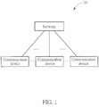
Fig. 1 is a schematic diagram of a wireless communication system according to an example of the present invention. -
Fig. 2 is a schematic diagram of a communication device according to an example of the present invention. -
Fig. 3 is a flowchart of a process according to an example of the present invention. -
Fig. 4 is a flowchart of a process according to an example of the present invention. -
Fig. 5 is a flowchart of a process according to an example of the present invention. -
Fig. 6 is a flowchart of a process according to an example of the present invention. -
Fig. 7 is a flowchart of a process according to an example of the present invention. -
Fig. 8 is a flowchart of a process according to an example of the present invention. -
Fig. 9 is a flowchart of a process according to an example of the present invention. -
Fig. 1 is a schematic diagram of awireless communication system 10 according to an example of the present invention. Thewireless communication system 10 is briefly composed of a network and a plurality of communication devices. InFig. 1 , the network and the communication devices are simply utilized for illustrating the structure of thewireless communication system 10. Practically, the network may be an evolved universal terrestrial radio access network (E-UTRAN) or next generation radio access network (NG-RAN) employing orthogonal frequency-division multiplexing (OFDM) and/or non-OFDM for communicating with the communication device. - The communication device may aggregate multiple component carriers (CCs) in a time division duplex (TDD) mode and/or a frequency division duplex (FDD) mode, to communicate with the network in the same frequency band or different frequency bands, when carrier aggregation (CA) or dual connectivity (DC) is supported. A cell may be configured with an uplink (UL) CC and a downlink (DL) CC. If the cell is a FDD cell, the UL CC(s) and the DL CC(s) may have different physical frequencies (e.g., carrier frequencies). If the cell is a TDD cell, the UL CC(s) and the DL CC(s) are the same CC(s).
- A communication device may be a user equipment (UE), a mobile phone, a laptop, a tablet computer, an electronic book, a portable computer system, a vehicle, or an aircraft. In addition, the network and the communication device can be seen as a transmitter or a receiver according to direction (i.e., transmission direction), e.g., for a UL, the communication device is the transmitter and the network is the receiver, and for a DL, the network is the transmitter and the communication device is the receiver.
-
Fig. 2 is a schematic diagram of acommunication device 20 according to an example of the present invention. Thecommunication device 20 may be a communication device or the network shown inFig. 1 , but is not limited herein. Thecommunication device 20 may include at least oneprocessing circuit 200 such as a microprocessor or Application Specific Integrated Circuit (ASIC), at least onestorage device 210 and at least onecommunication interfacing device 220. The at least onestorage device 210 may be any data storage device that may storeprogram codes 214, accessed and executed by the at least oneprocessing circuit 200. Examples of the at least onestorage device 210 include but are not limited to a subscriber identity module (SIM), read-only memory (ROM), flash memory, random-access memory (RAM), hard disk, optical data storage device, non-volatile storage device, non-transitory computer-readable medium (e.g., tangible media), etc. The at least onecommunication interfacing device 220 includes at least one transceiver and is used to transmit and receive signals (e.g., data, messages and/or packets) according to processing results of the at least oneprocessing circuit 200. - In the following examples, a UE is used to represent a communication device in
Fig. 1 , to simplify the illustration of the embodiments. - A buffer status report (BSR) transmitted by a UE to the network (e.g., RAN) carries information regarding how much data available for transmission is in a buffer associated to a medium access control (MAC) entity in the UE, i.e., buffer status. Then, the network may allocate a UL grant (e.g. , resources for a physical UL shared channel (PUSCH)) to the UE according to the buffer status.
- A buffer status reporting (BSR) procedure is used for providing the BSR to a serving evolved Node-B (eNB).
- Packet duplication (or data duplication) is going to be supported in the E-UTRAN or the NG-RAN, where a transmitter (e.g., the UE or the network) transmits a packet at least twice to improve reception reliability. In this situation, a receiver may misunderstand content of received packets and perform improper operations, when the received packets are duplicated packets (e.g., duplicated information).
- A
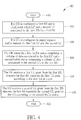
process 30 inFig. 3 is utilized in a first BS in the network shown inFig. 1 , and includes the following steps:Step 300: Start. Step 302: The first BS configures a first RB and configures a first LC and a second LC associated to the first RB, to a UE. Step 304: The first BS configures the UE to report separate buffer statuses for the first LC and the second LC associated to the first RB. Step 306: The first BS receives a first buffer status comprising a volume of data associated to the first LC and a second buffer status comprising a volume of data associated to the second LC, from the UE. Step 308: The first BS transmits a first UL grant to the UE according to the first buffer status. Step 310: The first BS transmits a second UL grant to the UE according to the second buffer status. Step 312: End. - A
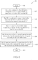
process 40 inFig. 4 is utilized in a UE, and includes the following steps:Step 400: Start. Step 402: The UE is configured a first RB and is configured a first LC and a second LC associated to the first RB, by a first BS. Step 404: The UE is configured to report separate buffer statuses for the first LC and the second LC. Step 406: The UE transmits a first buffer status comprising a volume of data associated to the first LC and a second buffer status comprising a volume of data associated to the second LC, to the first BS. Step 408: The UE receives a first UL grant from the first BS, wherein the first BS transmits the first UL grant according to the first buffer status. Step 410: The UE receives a second UL grant from the first BS, wherein the first BS transmits the second UL grant to the UE according to the second buffer status. Step 412: End. - In one example, the UE transmits at least one BSR including the first buffer status and the second buffer status, to the first BS. Each of the at least one BSR may be a MAC CE. In one example, a BSR of the at least one BSR includes a first LC identity (LCID) for indicating the first buffer status and a second LCID for indicating the second buffer status. In one example, the BSR may include a first identity (e.g., a first LCG identity) for indicating the first buffer status and a second identity (e.g., a second LCG identity) for indicating the second buffer status. In one example, the BSR does not include any identity for indicating the first buffer status and does not include any identity for indicating the second buffer status. Locations of the first buffer status and the second buffer status in the BSR are used for indicating or identifying the first buffer status and the second buffer status.
- In one example, the first buffer status indicates a first buffer size comprising the volume of data associated to the first LC. The first buffer size may or may not include a volume of data associated to a third LC. In one example, the second buffer status indicates a second buffer size comprising the volume of data associated to the second LC. The second buffer size may or may not include a volume of data associated to a third LC. The first buffer size may not include the volume of data associated to the second LC, and the second buffer size may not include the volume of data associated to the first LC.
- A
process 50 inFig. 5 is utilized in a first BS in the network shown inFig. 1 , and includes the following steps:Step 500: Start. Step 502: The first BS configures a first RB and configures a first LC and a second LC associated to the first RB, to a UE. Step 504: The first BS configures the UE to report a first buffer status for the first LC and configures the UE not to report a second buffer status for the second LC. Step 506: The first BS receives the first buffer status comprising a volume of data associated to the first LC, from the UE. Step 508: The first BS transmits a first UL grant to the UE according to the first buffer status. Step 510: The first BS transmits a second UL grant to the UE according to the first buffer status. Step 512: End. - According to the
processes processes - In one example, to transmit a first Packet Data Convergence Protocol (PDCP) PDU on the first RB twice, the UE generates a first Radio Link Control (RLC) PDU comprising the first PDCP PDU (e.g., RLC Service Data Unit (SDU)). The UE transmits the first RLC PDU via the first LC, and transmits the first RLC PDU via/using the second LC. The UE generates a first MAC PDU comprising the first RLC PDU and a first LCID, in response to the first UL grant, and generates a second MAC PDU comprising the first RLC PDU and a second LCID, in response to the second UL grant. The first MAC PDU may include a second RLC PDU from a third LC associated to a second RB or from the first LC or the second LC. The second RLC PDU may include a second PDCP PDU. The second RLC PDU may not include any PDCP PDU, e.g., the second RLC PDU is a RLC control PDU (e.g., RLC status PDU) . The UE neither includes the first RLC PDU twice (e.g., "the first RLC PDU + the first LCID" and "the first RLC PDU + the second LCID") in the first MAC PDU nor includes the first RLC PDU twice in the second MAC PDU. Then, the UE transmits the first MAC PDU to the first BS and the second MAC PDU to the first BS, e.g., on different carriers. For example, the UE transmits the first MAC PDU on a first carrier according to the first UL grant and the second MAC PDU on a second carrier according to the second UL grant. Thus, possibility for the first BS to successfully receive the first RLC PDU is increased.
- In one example, the first BS configures the UE to report a third buffer status for a third LC associated to a second RB. In one example, the first LC and the second LC may belong to a same LCG. In one example, the first LC and the second LC may belong to different LCGs. In one example, the first LC belongs to a LCG and the second LC does not belong to any LCG. In another example, the first LC and the second LC may not belong to any LCG.
- In one example, the first BS transmits one or more RRC messages to the UE to configure the first RB, and the first LC and the second LC associated to the first RB, and to configure the UE to report the first buffer status for the first LC and not to report the second buffer status for the second LC. The one or more RRC messages may include a RB identity of the first RB, the first LCID and the second LCID. The one or more RRC messages may be RRC Connection Reconfiguration message(s), RRC Connection Setup message(s), RRC Connection Reestablishment message (s) and/or RRC Connection Resume message(s). In one example, the first BS transmits a first RB configuration to the UE, to configure the first RB and the first LC and the second LC associated to the first RB. The first RB configuration may include the RB identity of the first RB, the identity of the first LC and the identity of the second LC. The one or more RRC messages may include the first RB configuration to be transmitted to the UE.
- In one example, when the UE receives the one or more RRC messages or the first RB configuration, the UE applies the one or more RRC messages or the first RB configuration by configuring the first RB and the first LC and the second LC associated to the first RB.
- The first RB may be a signaling RB or a data RB. The second RB may be a signaling RB or a data RB.
- A
process 60 inFig. 6 is utilized in a UE, and includes the following steps:Step 600: Start. Step 602: The UE is configured a first RB and is configured a first LC and a second LC associated to the first RB, by a first BS. Step 604: The UE is configured to report a first buffer status for the first LC and not to report a second buffer status for the second LC. Step 606: The UE transmits a first buffer status comprising a volume of data associated to the first LC, to the first BS. Step 608: The UE receives a first UL grant from the first BS, wherein the first BS transmits the first UL grant according to the first buffer status. Step 610: The UE receives a second UL grant from the first BS, wherein the first BS transmits the second UL grant to the UE according to the first buffer status. Step 612: End. - In one example, when the UE is configured to report the first buffer status for the first LC and not to report the second buffer status for the second LC, the UE may trigger a BSR transmission due to data available for transmission for the first LC but not (e.g., never) trigger a BSR transmission due to data available for transmission for the second LC. In one example, the UE transmits a RLC control PDU associated to the first RB via the first LC instead of the second LC such that the RLC control PDU may trigger a BSR transmission.
- In one example, the UE transmits a BSR including the first buffer status to the first BS. The BSR may be a MAC CE. In one example, the BSR may include a first LCID for indicating the first buffer status. In one example, the BSR may include a first identity (e.g., a first LCG identity) for indicating the first buffer status. In one example, the BSR may not include any identity for indicating the first buffer status. A location of the first buffer status in the BSR are used for indicating or identifying the first buffer status.
- The first buffer status indicates a first buffer size comprising the volume of data associated to the first LC. The first buffer size does not include the volume of data associated to the second LC.
- A
process 70 inFig. 7 is utilized in a UE, and includes the following steps:Step 700: Start. Step 702: The UE is configured a first RB and is configured a first LC and a second LC associated to the first RB, by a first BS. Step 704: The UE configures a PDCP entity for the first RB to process a plurality of PDCP SDUs to generate a plurality of PDCP PDUs. Step 706: The UE transmits a first buffer status comprising a volume of the plurality of PDCP SDUs or the plurality of PDCP PDUs and a second buffer status comprising the volume of the plurality of PDCP SDUs or the plurality of PDCP PDUs, to the first BS. Step 708: End. - In one example, the UE receives a first UL grant from the first BS on a first carrier, wherein the first BS transmits the first UL grant according to the first buffer status. The UE may receive a second UL grant from the first BS on a second carrier, wherein the first BS transmits the second UL grant to the UE according to the second buffer status. In one example, the first UL grant configures the UE to transmit a first transport block on a third carrier and the second UL grant configures the UE to transmit a second transport block on a fourth carrier.
- In one example, the UE may be configured to report separate buffer statuses for the first LC and the second LC by the first BS. For example, the first BS (or a second BS) may transmit a RRC message (e.g. RRCConnectionReconfiguration message) configuring the UE to report the separate buffer statuses. The UE performs the
step 706 in response to the RRC message. - In one example, the UE transmits a MAC PDU or a MAC CE comprising the first buffer status and the second buffer status to the first BS.
- In one example, the UE triggers transmission of the first buffer status and the second buffer status, when the UE detects at least one of the plurality of PDCP SDUs coming into a buffer (e.g., PDCP buffer) or when the UE generates the plurality of PDCP PDUs in the buffer.
- In one example, the UE may configure the PDCP entity according a PDCP configuration received from the first BS or a second BS.
- In one example, the PDCP SDUs are IP packets or Service Data Adaption Protocol (SDAP) PDUs.
- In one example of the
process 70, the UE does not duplicate the plurality of PDCP SDUs and the plurality of PDCP PDUs in the PDCP entity in order to report the first buffer status and the second buffer status. That is, the UE determines the plurality of PDCP SDUs or the plurality of PDCP PDUs available for transmission for both the first LC and the second LC. - In one example, the UE determines the plurality of PDCP SDUs or the plurality of PDCP PDUs available for transmission for both the first LC and the second LC, when duplication is activated by the UE. Thus, the UE transmits the first buffer status and the second buffer status. The UE may activate the duplication, when receiving a duplication activation command (e.g., a PDCP control PDU or a MAC CE) from the first BS.
- In one example, the UE may deactivate the duplication, when receiving a duplication deactivation command (e.g., a PDCP control PDU or a MAC CE) from the first BS. The UE may transmit the first buffer status but does not transmit the second buffer status in response to the deactivating. The UE may determine the plurality of PDCP SDUs or the plurality of PDCP PDUs available for transmission for only the first LC in response to the deactivating.
- In one example, the UE is configured a first RB and is configured a first LC and a second LC associated to the first RB, by a first BS in a RRC message (e.g., RRCConnectionReconfiguration message) transmitted from the first BS to the UE.
- The examples for the
process 70 may be applied to other processes, and are not repeated herein. - A
process 80 inFig. 8 is utilized in a UE, and includes the following steps:Step 800: Start. Step 802: The UE is configured a first RB and is configured a first LC and a second LC associated to the first RB, by a first BS. Step 804: The UE configures a first RLC entity for the first LC to process a plurality of RLC SDUs to generate a plurality of RLC PDUs. Step 806: The UE configures a second RLC entity for the second LC to transmit the plurality of RLC PDUs. Step 808: The UE transmits a first buffer status comprising a volume of the plurality of RLC SDUs or the plurality of RLC PDUs and a second buffer status comprising the volume of the plurality of RLC SDUs or the plurality of RLC PDUs, to the first BS. Step 810: End. - Examples described for the above processes may be applied to the
process 80, and are not repeated herein. - In one example, the UE triggers transmission of the first buffer status and the second buffer status, when the UE detects at least one of the plurality of RLC SDUs coming into a buffer (e.g., RLC buffer) or when the UE generates a plurality of PDCP PDUs in the buffer.
- In one example, the UE may configure the first RLC entity according to a first RLC configuration received from the first BS or a second BS. The UE may configure the second RLC entity according to a second RLC configuration received from the first BS or a second BS. The first RLC configuration and the second RLC configuration may be a same configuration (i.e., same information element) or different configurations (i.e., different information elements).
- In one example of the
process 80, the UE does not duplicate the plurality of RLC SDUs and the plurality of RLC PDUs in the second RLC entity in order to report the first buffer status and the second buffer status. That is, the UE determines the plurality of RLC SDUs or the plurality of RLC PDUs available for transmission for both the first LC and the second LC. - In one example, the UE determines the plurality of RLC SDUs or the plurality of RLC PDUs available for transmission for both the first LC and the second LC, when duplication is activated by the UE. Thus, the UE transmits the first buffer status and the second buffer status. The UE may activate the duplication, when receiving a duplication activation command (e.g., a PDCP control PDU or a MAC CE) from the first BS.
- In one example, the UE may deactivate the duplication, when receiving a duplication deactivation command (e.g., a PDCP control PDU or a MAC CE) from the first BS. The UE may determine the plurality of RLC SDUs or the plurality of RLC PDUs available for transmission for only the first LC in response to the deactivating. The UE may transmit the first buffer status but does not transmit the second buffer status.
- A
process 90 inFig. 9 is utilized in a UE, and includes the following steps:Step 900: Start. Step 902: The UE is configured a first RB and is configured a first LC and a second LC associated to the first RB, by a first BS. Step 904: The UE configures a PDCP entity for the first RB to process a plurality of PDCP SDUs to generate a plurality of PDCP PDUs. Step 906: The UE configures a first RLC entity for the first LC to process a plurality of RLC SDUs to generate a plurality of RLC PDUs. Step 908: The UE configures a second RLC entity for the second LC to transmit the plurality of RLC PDUs. Step 910: The UE transmits a first buffer status comprising a volume of the plurality of RLC SDUs or the plurality of RLC PDUs and a volume of the plurality of PDCP SDUs or the plurality of PDCP PDUs and a second buffer status comprising the volume of the plurality of RLC SDUs or the plurality of RLC PDUs and the volume of the plurality of PDCP SDUs or the plurality of PDCP PDUs, to the first BS. Step 912: End. - The
process 90 may be seen as a combination of theprocesses process 90, and are not repeated herein. - Those skilled in the art should readily make combinations, modifications and/or alterations on the abovementioned description and examples. For example, the skilled person easily makes new embodiments of the network based on the embodiments and examples of the UE, and makes new embodiments of the UE based on the embodiments and examples of the network. The abovementioned description, steps and/or processes including suggested steps can be realized by means that could be hardware, software, firmware (known as a combination of a hardware device and computer instructions and data that reside as read-only software on the hardware device), an electronic system, or combination thereof. An example of the means may be the
communication device 20. Any of the above processes and examples above may be compiled into theprogram codes 214. - To sum up, the present invention provides a method and a communication device for handling buffer status reporting for packet duplication. Thus, the problem that a receiver may misunderstand content of duplicated packets received from a transmitter and perform improper operations is solved.
- Those skilled in the art will readily observe that numerous modifications and alterations of the device and method may be made while retaining the teachings of the invention. Accordingly, the above disclosure should be construed as limited only by the metes and bounds of the appended claims.
Claims (15)
- A base station, BS, for handling buffer status reporting for data duplication, comprising:a storage device (210); anda processing circuit (200), coupled to the storage device (210), wherein the storage device (210) stores, and the processing circuit (200) is configured to execute, instructions of:configuring (302) a radio bearer, RB, and configuring a first logical channel, LC, and a second LC associated to the RB, to a communication device (20);configuring (304) the communication device (20) to report separate buffer statuses for the first LC and the second LC associated to the RB;receiving (306) a first buffer status comprising a volume of data associated to the first LC and a second buffer status comprising a volume of data associated to the second LC, from the communication device (20);transmitting (308) a first UL grant to the communication device (20) according to the first buffer status; andtransmitting (310) a second UL grant to the communication device (20) according to the second buffer status.
- The BS of claim 1, wherein the BS configures the RB and configures the first LC and the second LC associated to the RB by transmitting at least one radio resource control, RRC, message to the communication device (20).
- The BS of claim 2, wherein the at least one RRC message comprises a RB configuration for configuring the RB and for configuring the first LC and the second LC associated to the RB.
- A communication device (20) for handling buffer status reporting for data duplication, comprising:a storage device (210); anda processing circuit (200), coupled to the storage device (210), wherein the storage device (210) stores, and the processing circuit (200) is configured to execute, instructions of:having a first radio bearer, RB, a first logical channel, LC, and a second LC associated to the first RB, configured by a first base station, BS, (402);configuring (404) the UE to report separate buffer statuses for the first LC and the second LC;transmitting (406) a first buffer status comprising a volume of data associated to the first LC and a second buffer status comprising a volume of data associated to the second LC, to the first BS;receiving (408) a first UL grant from the first BS, wherein the first BS transmits the first UL grant according to the first buffer status; andreceiving (410) a second UL grant from the first BS, wherein the first BS transmits the second UL grant to the communication device according to the second buffer status.
- The communication device of claim 4, wherein the instruction of transmitting (406) comprises transmitting a buffer status report, BSR, comprising the first buffer status and the second buffer status to the first BS, wherein the BSR comprises a first identity for indicating the first buffer status and a second identity for indicating the second buffer status.
- The communication device of claim 4, wherein locations of the first buffer status and the second buffer status indicate the first buffer status and the second buffer status.
- The communication device of claim 4, wherein the instructions further comprise:
configuring a Packet Data Convergence Protocol, PDCP, entity for the first RB to process a plurality of PDCP service data units, SDUs, to generate a plurality of PDCP Protocol Data Units, PDUs;
wherein the volume of data comprises a volume of the plurality of PDCP SDUs or the plurality of PDCP PDUs and the second buffer status comprises the volume of the plurality of PDCP SDUs or the plurality of PDCP PDUs. - The communication device of claim 7, wherein the instructions further comprise:
triggering the transmission of the first buffer status and the second buffer status, when the communication device (20) detects at least one of the plurality of PDCP SDUs coming into a buffer or when the communication device (20) generates the plurality of PDCP PDUs in the buffer. - The communication device of claim 4, wherein the first buffer status and the second buffer status are transmitted in a medium access control, MAC, PDU or a MAC control element, CE, to the first BS.
- The communication device of claim 4, wherein the instructions further comprise:configuring a first radio link control, RLC, entity for the first LC to process a plurality of RLC SDUs to generate a plurality of RLC PDUs; andconfiguring a second RLC entity for the second LC to transmit the plurality of RLC PDUs;wherein the volume of data comprises a volume of the plurality of RLC SDUs or the plurality of RLC PDUs and the second buffer status comprises the volume of the plurality of RLC SDUs or the plurality of RLC PDUs.
- The communication device of claim 10, wherein the instructions further comprise: triggering the transmission of the first buffer status and the second buffer status, when the communication device (20) detects at least one of the plurality of RLC SDUs coming into a buffer or when the communication device (20) generates the plurality of RLC PDUs in the buffer.
- A base station, BS, for handling buffer status reporting for data duplication, comprising:a storage device (210); anda processing circuit (220), coupled to the storage device (210), wherein the storage device (210) stores, and the processing circuit (200) is configured to execute, instructions of:configuring (502) a radio bearer, RB, and configuring a first logical channel, LC, and a second LC associated to the RB, to a communication device (20);configuring (504) the communication device (20) to report a first buffer status for the first LC and configuring the communication device (20) not to report a second buffer status for the second LC;receiving (506) the first buffer status comprising a volume of data associated to the first LC, from the communication device (20);transmitting (508) a first UL grant to the communication device according to the first buffer status; and transmitting (510) a second UL grant to the communication device according to the first buffer status.
- The BS of claim 12, wherein the first LC and the second LC belong to a same LC group, LCG, or different LCGs.
- The BS of claim 12, wherein the BS configures the RB and configures the first LC and the second LC associated to the RB by transmitting at least one radio resource control, RRC, message to the communication device (20).
- The BS of claim 14, wherein the at least one RRC message comprises a RB configuration for configuring the RB and for configuring the first LC and the second LC associated to the RB.
Applications Claiming Priority (2)
| Application Number | Priority Date | Filing Date | Title |
|---|---|---|---|
| US201762474601P | 2017-03-21 | 2017-03-21 | |
| US201762523750P | 2017-06-22 | 2017-06-22 |
Publications (2)
| Publication Number | Publication Date |
|---|---|
| EP3379863A1 EP3379863A1 (en) | 2018-09-26 |
| EP3379863B1 true EP3379863B1 (en) | 2020-02-26 |
Family
ID=61768066
Family Applications (1)
| Application Number | Title | Priority Date | Filing Date |
|---|---|---|---|
| EP18163023.7A Active EP3379863B1 (en) | 2017-03-21 | 2018-03-21 | Device and method of handling buffer status reporting for packet duplication |
Country Status (4)
| Country | Link |
|---|---|
| US (1) | US10667170B2 (en) |
| EP (1) | EP3379863B1 (en) |
| CN (1) | CN108632893B (en) |
| TW (1) | TWI706652B (en) |
Families Citing this family (5)
| Publication number | Priority date | Publication date | Assignee | Title |
|---|---|---|---|---|
| MX2019011641A (en) * | 2017-04-02 | 2019-12-05 | Fg innovation co ltd | Logical channel data packet transmission method and wireless communication system. |
| KR102318015B1 (en) | 2017-04-28 | 2021-10-27 | 삼성전자 주식회사 | Method and appatarus for indicating data length according to data type in wireless communication system |
| CN110521232A (en) * | 2017-07-28 | 2019-11-29 | Oppo广东移动通信有限公司 | Data transmission method and Related product |
| CN110972337B (en) * | 2018-09-29 | 2021-09-14 | 中国移动通信有限公司研究院 | Data transmission method, device and system, SDAP entity and storage medium |
| CN113940122A (en) * | 2019-08-15 | 2022-01-14 | 华为技术有限公司 | Method, device and system for determining association between logical channel groups |
Family Cites Families (16)
| Publication number | Priority date | Publication date | Assignee | Title |
|---|---|---|---|---|
| US8305901B2 (en) | 2008-09-22 | 2012-11-06 | Htc Corporation | Method of generating a buffer status for a wireless communication system and related device |
| CN101932052B (en) * | 2009-06-23 | 2016-08-24 | 华为技术有限公司 | A kind of changing method, user terminal and network equipment |
| CN102118858B (en) * | 2009-12-31 | 2013-09-11 | 电信科学技术研究院 | Method, system and device for allocating logical channel identifiers (LCID) and determining logical channels |
| CN107249197B (en) * | 2012-06-04 | 2019-12-13 | 电信科学技术研究院 | Method, system and equipment for reporting buffer status |
| JP6352304B2 (en) * | 2013-01-11 | 2018-07-04 | エルジー エレクトロニクス インコーポレイティド | Method for reporting buffer status and communication device therefor |
| KR20140107088A (en) * | 2013-02-27 | 2014-09-04 | 주식회사 케이티 | Methods and apparatuses for transmitting buffer status report of a user equipment in small cell deployments |
| CN104285487A (en) * | 2013-05-10 | 2015-01-14 | 华为技术有限公司 | Scheduling method, user equipment, and base station |
| CN105230103B (en) * | 2013-05-17 | 2019-07-12 | 寰发股份有限公司 | Report the method and user equipment of BSR |
| US10075940B2 (en) * | 2013-08-09 | 2018-09-11 | Kt Corporation | Method for transmitting buffer status report in device-to-device communication, and device thereof |
| US9924405B2 (en) * | 2013-10-04 | 2018-03-20 | Industrial Technology Research Institute | Method for buffer status report in dual connectivity |
| EP3064015B1 (en) * | 2013-11-01 | 2019-12-11 | Telefonaktiebolaget LM Ericsson (publ) | Radio base station, wireless terminal, methods performed therein, computer program, and computer-readable storage medium |
| WO2016035987A1 (en) * | 2014-09-04 | 2016-03-10 | Lg Electronics Inc. | Method for configuring a new prohibition buffer status reporting timer in a d2d communication system and device therefor |
| US9872313B2 (en) * | 2014-10-02 | 2018-01-16 | Qualcomm Incorporated | Contention based uplink transmissions for latency reduction |
| EP3089540B1 (en) | 2015-04-28 | 2018-10-17 | HTC Corporation | Device and method of reporting a buffer status report |
| US10405225B2 (en) * | 2015-07-08 | 2019-09-03 | Lg Electronics Inc. | Method for triggering a buffer status report in dual connectivity and a device therefor |
| US10212726B2 (en) * | 2015-10-23 | 2019-02-19 | Electronics And Telecommunications Research Institute | Method and apparatus for transmitting uplink signal in mobile communication system of unlicensed band |
-
2018
- 2018-03-21 EP EP18163023.7A patent/EP3379863B1/en active Active
- 2018-03-21 CN CN201810236503.7A patent/CN108632893B/en active Active
- 2018-03-21 US US15/927,096 patent/US10667170B2/en active Active
- 2018-03-21 TW TW107109681A patent/TWI706652B/en active
Non-Patent Citations (1)
| Title |
|---|
| None * |
Also Published As
| Publication number | Publication date |
|---|---|
| EP3379863A1 (en) | 2018-09-26 |
| CN108632893B (en) | 2023-02-03 |
| US10667170B2 (en) | 2020-05-26 |
| TW201836336A (en) | 2018-10-01 |
| TWI706652B (en) | 2020-10-01 |
| CN108632893A (en) | 2018-10-09 |
| US20180279163A1 (en) | 2018-09-27 |
Similar Documents
| Publication | Publication Date | Title |
|---|---|---|
| EP3694255B1 (en) | Base station and method of handling bandwidth parts | |
| US10313934B2 (en) | Device and method of handling communication | |
| CN111147218B (en) | Communication method, device and equipment | |
| EP3379863B1 (en) | Device and method of handling buffer status reporting for packet duplication | |
| TWI629913B (en) | Device and method for handling dual cellular system aggregation | |
| EP3595392B1 (en) | Data transmission method, terminal device, and network device | |
| US10575349B2 (en) | Device and method for handling a new radio connection in inter-system mobility | |
| EP3331276B1 (en) | Device and method of handling data transmissions after a handover | |
| US10321502B2 (en) | Terminal device, base station apparatus, communication system, communication control method, and integrated circuit | |
| EP3376702B1 (en) | Method and apparatus for transmitting duplication data using multiple carriers | |
| EP3442267B1 (en) | Network for handling a bearer change in dual connectivity | |
| EP3637896B1 (en) | Resource scheduling method, terminal device, and network device | |
| EP3410816A1 (en) | Device and method for handling measurement configuration and signaling radio bearer | |
| EP3402308A1 (en) | Coordination between multirat base stations in dual connectivity | |
| US10708929B2 (en) | Device and method of handling scheduling request for logical channel | |
| US20190053112A1 (en) | Device and Method of Handling a Secondary Node Change in Dual Connectivity | |
| US9485720B2 (en) | Method and device for controlling identification of a cell in communication system | |
| WO2024020728A1 (en) | Methods and apparatuses for simultaneous transmission on multiple paths |
Legal Events
| Date | Code | Title | Description |
|---|---|---|---|
| PUAI | Public reference made under article 153(3) epc to a published international application that has entered the european phase |
Free format text: ORIGINAL CODE: 0009012 |
|
| STAA | Information on the status of an ep patent application or granted ep patent |
Free format text: STATUS: REQUEST FOR EXAMINATION WAS MADE |
|
| 17P | Request for examination filed |
Effective date: 20180321 |
|
| AK | Designated contracting states |
Kind code of ref document: A1 Designated state(s): AL AT BE BG CH CY CZ DE DK EE ES FI FR GB GR HR HU IE IS IT LI LT LU LV MC MK MT NL NO PL PT RO RS SE SI SK SM TR |
|
| AX | Request for extension of the european patent |
Extension state: BA ME |
|
| STAA | Information on the status of an ep patent application or granted ep patent |
Free format text: STATUS: EXAMINATION IS IN PROGRESS |
|
| 17Q | First examination report despatched |
Effective date: 20181017 |
|
| RBV | Designated contracting states (corrected) |
Designated state(s): AL AT BE BG CH CY CZ DE DK EE ES FI FR GB GR HR HU IE IS IT LI LT LU LV MC MK MT NL NO PL PT RO RS SE SI SK SM TR |
|
| GRAP | Despatch of communication of intention to grant a patent |
Free format text: ORIGINAL CODE: EPIDOSNIGR1 |
|
| STAA | Information on the status of an ep patent application or granted ep patent |
Free format text: STATUS: GRANT OF PATENT IS INTENDED |
|
| RIC1 | Information provided on ipc code assigned before grant |
Ipc: H04W 76/15 20180101ALI20190902BHEP Ipc: H04W 72/14 20090101ALN20190902BHEP Ipc: H04W 28/02 20090101AFI20190902BHEP Ipc: H04W 72/04 20090101ALN20190902BHEP Ipc: H04W 72/12 20090101ALI20190902BHEP |
|
| INTG | Intention to grant announced |
Effective date: 20190917 |
|
| GRAS | Grant fee paid |
Free format text: ORIGINAL CODE: EPIDOSNIGR3 |
|
| GRAA | (expected) grant |
Free format text: ORIGINAL CODE: 0009210 |
|
| STAA | Information on the status of an ep patent application or granted ep patent |
Free format text: STATUS: THE PATENT HAS BEEN GRANTED |
|
| AK | Designated contracting states |
Kind code of ref document: B1 Designated state(s): AL AT BE BG CH CY CZ DE DK EE ES FI FR GB GR HR HU IE IS IT LI LT LU LV MC MK MT NL NO PL PT RO RS SE SI SK SM TR |
|
| REG | Reference to a national code |
Ref country code: GB Ref legal event code: FG4D |
|
| REG | Reference to a national code |
Ref country code: CH Ref legal event code: EP |
|
| REG | Reference to a national code |
Ref country code: AT Ref legal event code: REF Ref document number: 1239202 Country of ref document: AT Kind code of ref document: T Effective date: 20200315 |
|
| REG | Reference to a national code |
Ref country code: IE Ref legal event code: FG4D |
|
| REG | Reference to a national code |
Ref country code: DE Ref legal event code: R096 Ref document number: 602018002597 Country of ref document: DE |
|
| REG | Reference to a national code |
Ref country code: NL Ref legal event code: FP |
|
| PG25 | Lapsed in a contracting state [announced via postgrant information from national office to epo] |
Ref country code: FI Free format text: LAPSE BECAUSE OF FAILURE TO SUBMIT A TRANSLATION OF THE DESCRIPTION OR TO PAY THE FEE WITHIN THE PRESCRIBED TIME-LIMIT Effective date: 20200226 Ref country code: RS Free format text: LAPSE BECAUSE OF FAILURE TO SUBMIT A TRANSLATION OF THE DESCRIPTION OR TO PAY THE FEE WITHIN THE PRESCRIBED TIME-LIMIT Effective date: 20200226 Ref country code: NO Free format text: LAPSE BECAUSE OF FAILURE TO SUBMIT A TRANSLATION OF THE DESCRIPTION OR TO PAY THE FEE WITHIN THE PRESCRIBED TIME-LIMIT Effective date: 20200526 |
|
| REG | Reference to a national code |
Ref country code: LT Ref legal event code: MG4D |
|
| PG25 | Lapsed in a contracting state [announced via postgrant information from national office to epo] |
Ref country code: HR Free format text: LAPSE BECAUSE OF FAILURE TO SUBMIT A TRANSLATION OF THE DESCRIPTION OR TO PAY THE FEE WITHIN THE PRESCRIBED TIME-LIMIT Effective date: 20200226 Ref country code: BG Free format text: LAPSE BECAUSE OF FAILURE TO SUBMIT A TRANSLATION OF THE DESCRIPTION OR TO PAY THE FEE WITHIN THE PRESCRIBED TIME-LIMIT Effective date: 20200526 Ref country code: LV Free format text: LAPSE BECAUSE OF FAILURE TO SUBMIT A TRANSLATION OF THE DESCRIPTION OR TO PAY THE FEE WITHIN THE PRESCRIBED TIME-LIMIT Effective date: 20200226 Ref country code: GR Free format text: LAPSE BECAUSE OF FAILURE TO SUBMIT A TRANSLATION OF THE DESCRIPTION OR TO PAY THE FEE WITHIN THE PRESCRIBED TIME-LIMIT Effective date: 20200527 Ref country code: IS Free format text: LAPSE BECAUSE OF FAILURE TO SUBMIT A TRANSLATION OF THE DESCRIPTION OR TO PAY THE FEE WITHIN THE PRESCRIBED TIME-LIMIT Effective date: 20200626 Ref country code: SE Free format text: LAPSE BECAUSE OF FAILURE TO SUBMIT A TRANSLATION OF THE DESCRIPTION OR TO PAY THE FEE WITHIN THE PRESCRIBED TIME-LIMIT Effective date: 20200226 |
|
| PG25 | Lapsed in a contracting state [announced via postgrant information from national office to epo] |
Ref country code: CZ Free format text: LAPSE BECAUSE OF FAILURE TO SUBMIT A TRANSLATION OF THE DESCRIPTION OR TO PAY THE FEE WITHIN THE PRESCRIBED TIME-LIMIT Effective date: 20200226 Ref country code: RO Free format text: LAPSE BECAUSE OF FAILURE TO SUBMIT A TRANSLATION OF THE DESCRIPTION OR TO PAY THE FEE WITHIN THE PRESCRIBED TIME-LIMIT Effective date: 20200226 Ref country code: DK Free format text: LAPSE BECAUSE OF FAILURE TO SUBMIT A TRANSLATION OF THE DESCRIPTION OR TO PAY THE FEE WITHIN THE PRESCRIBED TIME-LIMIT Effective date: 20200226 Ref country code: SM Free format text: LAPSE BECAUSE OF FAILURE TO SUBMIT A TRANSLATION OF THE DESCRIPTION OR TO PAY THE FEE WITHIN THE PRESCRIBED TIME-LIMIT Effective date: 20200226 Ref country code: EE Free format text: LAPSE BECAUSE OF FAILURE TO SUBMIT A TRANSLATION OF THE DESCRIPTION OR TO PAY THE FEE WITHIN THE PRESCRIBED TIME-LIMIT Effective date: 20200226 Ref country code: LT Free format text: LAPSE BECAUSE OF FAILURE TO SUBMIT A TRANSLATION OF THE DESCRIPTION OR TO PAY THE FEE WITHIN THE PRESCRIBED TIME-LIMIT Effective date: 20200226 Ref country code: SK Free format text: LAPSE BECAUSE OF FAILURE TO SUBMIT A TRANSLATION OF THE DESCRIPTION OR TO PAY THE FEE WITHIN THE PRESCRIBED TIME-LIMIT Effective date: 20200226 Ref country code: ES Free format text: LAPSE BECAUSE OF FAILURE TO SUBMIT A TRANSLATION OF THE DESCRIPTION OR TO PAY THE FEE WITHIN THE PRESCRIBED TIME-LIMIT Effective date: 20200226 Ref country code: PT Free format text: LAPSE BECAUSE OF FAILURE TO SUBMIT A TRANSLATION OF THE DESCRIPTION OR TO PAY THE FEE WITHIN THE PRESCRIBED TIME-LIMIT Effective date: 20200719 |
|
| REG | Reference to a national code |
Ref country code: AT Ref legal event code: MK05 Ref document number: 1239202 Country of ref document: AT Kind code of ref document: T Effective date: 20200226 |
|
| REG | Reference to a national code |
Ref country code: DE Ref legal event code: R097 Ref document number: 602018002597 Country of ref document: DE |
|
| PG25 | Lapsed in a contracting state [announced via postgrant information from national office to epo] |
Ref country code: MC Free format text: LAPSE BECAUSE OF FAILURE TO SUBMIT A TRANSLATION OF THE DESCRIPTION OR TO PAY THE FEE WITHIN THE PRESCRIBED TIME-LIMIT Effective date: 20200226 |
|
| REG | Reference to a national code |
Ref country code: BE Ref legal event code: MM Effective date: 20200331 |
|
| PG25 | Lapsed in a contracting state [announced via postgrant information from national office to epo] |
Ref country code: LU Free format text: LAPSE BECAUSE OF NON-PAYMENT OF DUE FEES Effective date: 20200321 |
|
| PLBE | No opposition filed within time limit |
Free format text: ORIGINAL CODE: 0009261 |
|
| STAA | Information on the status of an ep patent application or granted ep patent |
Free format text: STATUS: NO OPPOSITION FILED WITHIN TIME LIMIT |
|
| PG25 | Lapsed in a contracting state [announced via postgrant information from national office to epo] |
Ref country code: AT Free format text: LAPSE BECAUSE OF FAILURE TO SUBMIT A TRANSLATION OF THE DESCRIPTION OR TO PAY THE FEE WITHIN THE PRESCRIBED TIME-LIMIT Effective date: 20200226 Ref country code: IT Free format text: LAPSE BECAUSE OF FAILURE TO SUBMIT A TRANSLATION OF THE DESCRIPTION OR TO PAY THE FEE WITHIN THE PRESCRIBED TIME-LIMIT Effective date: 20200226 Ref country code: IE Free format text: LAPSE BECAUSE OF NON-PAYMENT OF DUE FEES Effective date: 20200321 |
|
| 26N | No opposition filed |
Effective date: 20201127 |
|
| PG25 | Lapsed in a contracting state [announced via postgrant information from national office to epo] |
Ref country code: BE Free format text: LAPSE BECAUSE OF NON-PAYMENT OF DUE FEES Effective date: 20200331 Ref country code: PL Free format text: LAPSE BECAUSE OF FAILURE TO SUBMIT A TRANSLATION OF THE DESCRIPTION OR TO PAY THE FEE WITHIN THE PRESCRIBED TIME-LIMIT Effective date: 20200226 Ref country code: SI Free format text: LAPSE BECAUSE OF FAILURE TO SUBMIT A TRANSLATION OF THE DESCRIPTION OR TO PAY THE FEE WITHIN THE PRESCRIBED TIME-LIMIT Effective date: 20200226 |
|
| REG | Reference to a national code |
Ref country code: CH Ref legal event code: PL |
|
| PG25 | Lapsed in a contracting state [announced via postgrant information from national office to epo] |
Ref country code: CH Free format text: LAPSE BECAUSE OF NON-PAYMENT OF DUE FEES Effective date: 20210331 Ref country code: LI Free format text: LAPSE BECAUSE OF NON-PAYMENT OF DUE FEES Effective date: 20210331 |
|
| PG25 | Lapsed in a contracting state [announced via postgrant information from national office to epo] |
Ref country code: TR Free format text: LAPSE BECAUSE OF FAILURE TO SUBMIT A TRANSLATION OF THE DESCRIPTION OR TO PAY THE FEE WITHIN THE PRESCRIBED TIME-LIMIT Effective date: 20200226 Ref country code: MT Free format text: LAPSE BECAUSE OF FAILURE TO SUBMIT A TRANSLATION OF THE DESCRIPTION OR TO PAY THE FEE WITHIN THE PRESCRIBED TIME-LIMIT Effective date: 20200226 Ref country code: CY Free format text: LAPSE BECAUSE OF FAILURE TO SUBMIT A TRANSLATION OF THE DESCRIPTION OR TO PAY THE FEE WITHIN THE PRESCRIBED TIME-LIMIT Effective date: 20200226 |
|
| PG25 | Lapsed in a contracting state [announced via postgrant information from national office to epo] |
Ref country code: MK Free format text: LAPSE BECAUSE OF FAILURE TO SUBMIT A TRANSLATION OF THE DESCRIPTION OR TO PAY THE FEE WITHIN THE PRESCRIBED TIME-LIMIT Effective date: 20200226 Ref country code: AL Free format text: LAPSE BECAUSE OF FAILURE TO SUBMIT A TRANSLATION OF THE DESCRIPTION OR TO PAY THE FEE WITHIN THE PRESCRIBED TIME-LIMIT Effective date: 20200226 |
|
| PGFP | Annual fee paid to national office [announced via postgrant information from national office to epo] |
Ref country code: NL Payment date: 20230215 Year of fee payment: 6 |
|
| PGFP | Annual fee paid to national office [announced via postgrant information from national office to epo] |
Ref country code: FR Payment date: 20230208 Year of fee payment: 6 |
|
| PGFP | Annual fee paid to national office [announced via postgrant information from national office to epo] |
Ref country code: GB Payment date: 20230126 Year of fee payment: 6 Ref country code: DE Payment date: 20230125 Year of fee payment: 6 |
|
| P01 | Opt-out of the competence of the unified patent court (upc) registered |
Effective date: 20230602 |
|
| PGFP | Annual fee paid to national office [announced via postgrant information from national office to epo] |
Ref country code: NL Payment date: 20240108 Year of fee payment: 7 |