EP3379823A1 - Inspection device, image processing device, correction value calculating method, image processing method, inspection program, and correction program - Google Patents
Inspection device, image processing device, correction value calculating method, image processing method, inspection program, and correction program Download PDFInfo
- Publication number
- EP3379823A1 EP3379823A1 EP16866013.2A EP16866013A EP3379823A1 EP 3379823 A1 EP3379823 A1 EP 3379823A1 EP 16866013 A EP16866013 A EP 16866013A EP 3379823 A1 EP3379823 A1 EP 3379823A1
- Authority
- EP
- European Patent Office
- Prior art keywords
- image data
- correction
- horizontal line
- unit
- value
- Prior art date
- Legal status (The legal status is an assumption and is not a legal conclusion. Google has not performed a legal analysis and makes no representation as to the accuracy of the status listed.)
- Withdrawn
Links
- 238000007689 inspection Methods 0.000 title claims abstract description 108
- 238000012937 correction Methods 0.000 title claims description 166
- 238000012545 processing Methods 0.000 title claims description 142
- 238000000034 method Methods 0.000 title claims description 16
- 238000003672 processing method Methods 0.000 title claims description 5
- 238000003384 imaging method Methods 0.000 claims abstract description 231
- 230000014509 gene expression Effects 0.000 claims description 15
- 239000011159 matrix material Substances 0.000 claims description 15
- 238000012546 transfer Methods 0.000 description 54
- 230000005540 biological transmission Effects 0.000 description 17
- 238000006243 chemical reaction Methods 0.000 description 16
- 238000010586 diagram Methods 0.000 description 12
- 238000007796 conventional method Methods 0.000 description 10
- 239000003990 capacitor Substances 0.000 description 6
- 230000007274 generation of a signal involved in cell-cell signaling Effects 0.000 description 6
- 239000000284 extract Substances 0.000 description 5
- 230000006870 function Effects 0.000 description 5
- 238000005286 illumination Methods 0.000 description 3
- 238000005070 sampling Methods 0.000 description 3
- 230000008878 coupling Effects 0.000 description 2
- 238000010168 coupling process Methods 0.000 description 2
- 238000005859 coupling reaction Methods 0.000 description 2
- 230000000694 effects Effects 0.000 description 2
- 238000005401 electroluminescence Methods 0.000 description 2
- 238000001727 in vivo Methods 0.000 description 2
- 230000000295 complement effect Effects 0.000 description 1
- 238000013461 design Methods 0.000 description 1
- 238000009792 diffusion process Methods 0.000 description 1
- 238000005516 engineering process Methods 0.000 description 1
- 238000007667 floating Methods 0.000 description 1
- 229910052736 halogen Inorganic materials 0.000 description 1
- 150000002367 halogens Chemical class 0.000 description 1
- 239000004973 liquid crystal related substance Substances 0.000 description 1
- 229910044991 metal oxide Inorganic materials 0.000 description 1
- 150000004706 metal oxides Chemical class 0.000 description 1
- 230000003287 optical effect Effects 0.000 description 1
- 239000004065 semiconductor Substances 0.000 description 1
- 238000007493 shaping process Methods 0.000 description 1
- 230000006641 stabilisation Effects 0.000 description 1
- 238000011105 stabilization Methods 0.000 description 1
Images








Classifications
-
- G—PHYSICS
- G02—OPTICS
- G02B—OPTICAL ELEMENTS, SYSTEMS OR APPARATUS
- G02B23/00—Telescopes, e.g. binoculars; Periscopes; Instruments for viewing the inside of hollow bodies; Viewfinders; Optical aiming or sighting devices
- G02B23/24—Instruments or systems for viewing the inside of hollow bodies, e.g. fibrescopes
- G02B23/2476—Non-optical details, e.g. housings, mountings, supports
- G02B23/2484—Arrangements in relation to a camera or imaging device
-
- H—ELECTRICITY
- H04—ELECTRIC COMMUNICATION TECHNIQUE
- H04N—PICTORIAL COMMUNICATION, e.g. TELEVISION
- H04N25/00—Circuitry of solid-state image sensors [SSIS]; Control thereof
- H04N25/60—Noise processing, e.g. detecting, correcting, reducing or removing noise
- H04N25/67—Noise processing, e.g. detecting, correcting, reducing or removing noise applied to fixed-pattern noise, e.g. non-uniformity of response
- H04N25/671—Noise processing, e.g. detecting, correcting, reducing or removing noise applied to fixed-pattern noise, e.g. non-uniformity of response for non-uniformity detection or correction
- H04N25/677—Noise processing, e.g. detecting, correcting, reducing or removing noise applied to fixed-pattern noise, e.g. non-uniformity of response for non-uniformity detection or correction for reducing the column or line fixed pattern noise
-
- A—HUMAN NECESSITIES
- A61—MEDICAL OR VETERINARY SCIENCE; HYGIENE
- A61B—DIAGNOSIS; SURGERY; IDENTIFICATION
- A61B1/00—Instruments for performing medical examinations of the interior of cavities or tubes of the body by visual or photographical inspection, e.g. endoscopes; Illuminating arrangements therefor
- A61B1/00002—Operational features of endoscopes
- A61B1/00004—Operational features of endoscopes characterised by electronic signal processing
- A61B1/00006—Operational features of endoscopes characterised by electronic signal processing of control signals
-
- A—HUMAN NECESSITIES
- A61—MEDICAL OR VETERINARY SCIENCE; HYGIENE
- A61B—DIAGNOSIS; SURGERY; IDENTIFICATION
- A61B1/00—Instruments for performing medical examinations of the interior of cavities or tubes of the body by visual or photographical inspection, e.g. endoscopes; Illuminating arrangements therefor
- A61B1/00002—Operational features of endoscopes
- A61B1/00004—Operational features of endoscopes characterised by electronic signal processing
- A61B1/00009—Operational features of endoscopes characterised by electronic signal processing of image signals during a use of endoscope
- A61B1/000095—Operational features of endoscopes characterised by electronic signal processing of image signals during a use of endoscope for image enhancement
-
- A—HUMAN NECESSITIES
- A61—MEDICAL OR VETERINARY SCIENCE; HYGIENE
- A61B—DIAGNOSIS; SURGERY; IDENTIFICATION
- A61B1/00—Instruments for performing medical examinations of the interior of cavities or tubes of the body by visual or photographical inspection, e.g. endoscopes; Illuminating arrangements therefor
- A61B1/00002—Operational features of endoscopes
- A61B1/0002—Operational features of endoscopes provided with data storages
-
- A—HUMAN NECESSITIES
- A61—MEDICAL OR VETERINARY SCIENCE; HYGIENE
- A61B—DIAGNOSIS; SURGERY; IDENTIFICATION
- A61B1/00—Instruments for performing medical examinations of the interior of cavities or tubes of the body by visual or photographical inspection, e.g. endoscopes; Illuminating arrangements therefor
- A61B1/04—Instruments for performing medical examinations of the interior of cavities or tubes of the body by visual or photographical inspection, e.g. endoscopes; Illuminating arrangements therefor combined with photographic or television appliances
- A61B1/05—Instruments for performing medical examinations of the interior of cavities or tubes of the body by visual or photographical inspection, e.g. endoscopes; Illuminating arrangements therefor combined with photographic or television appliances characterised by the image sensor, e.g. camera, being in the distal end portion
-
- H—ELECTRICITY
- H04—ELECTRIC COMMUNICATION TECHNIQUE
- H04N—PICTORIAL COMMUNICATION, e.g. TELEVISION
- H04N23/00—Cameras or camera modules comprising electronic image sensors; Control thereof
- H04N23/60—Control of cameras or camera modules
-
- H—ELECTRICITY
- H04—ELECTRIC COMMUNICATION TECHNIQUE
- H04N—PICTORIAL COMMUNICATION, e.g. TELEVISION
- H04N25/00—Circuitry of solid-state image sensors [SSIS]; Control thereof
- H04N25/60—Noise processing, e.g. detecting, correcting, reducing or removing noise
- H04N25/63—Noise processing, e.g. detecting, correcting, reducing or removing noise applied to dark current
- H04N25/633—Noise processing, e.g. detecting, correcting, reducing or removing noise applied to dark current by using optical black pixels
-
- H—ELECTRICITY
- H04—ELECTRIC COMMUNICATION TECHNIQUE
- H04N—PICTORIAL COMMUNICATION, e.g. TELEVISION
- H04N25/00—Circuitry of solid-state image sensors [SSIS]; Control thereof
- H04N25/70—SSIS architectures; Circuits associated therewith
- H04N25/76—Addressed sensors, e.g. MOS or CMOS sensors
- H04N25/78—Readout circuits for addressed sensors, e.g. output amplifiers or A/D converters
-
- H—ELECTRICITY
- H04—ELECTRIC COMMUNICATION TECHNIQUE
- H04N—PICTORIAL COMMUNICATION, e.g. TELEVISION
- H04N5/00—Details of television systems
- H04N5/76—Television signal recording
- H04N5/765—Interface circuits between an apparatus for recording and another apparatus
- H04N5/77—Interface circuits between an apparatus for recording and another apparatus between a recording apparatus and a television camera
- H04N5/772—Interface circuits between an apparatus for recording and another apparatus between a recording apparatus and a television camera the recording apparatus and the television camera being placed in the same enclosure
-
- A—HUMAN NECESSITIES
- A61—MEDICAL OR VETERINARY SCIENCE; HYGIENE
- A61B—DIAGNOSIS; SURGERY; IDENTIFICATION
- A61B1/00—Instruments for performing medical examinations of the interior of cavities or tubes of the body by visual or photographical inspection, e.g. endoscopes; Illuminating arrangements therefor
- A61B1/00002—Operational features of endoscopes
- A61B1/00025—Operational features of endoscopes characterised by power management
-
- A—HUMAN NECESSITIES
- A61—MEDICAL OR VETERINARY SCIENCE; HYGIENE
- A61B—DIAGNOSIS; SURGERY; IDENTIFICATION
- A61B1/00—Instruments for performing medical examinations of the interior of cavities or tubes of the body by visual or photographical inspection, e.g. endoscopes; Illuminating arrangements therefor
- A61B1/04—Instruments for performing medical examinations of the interior of cavities or tubes of the body by visual or photographical inspection, e.g. endoscopes; Illuminating arrangements therefor combined with photographic or television appliances
- A61B1/045—Control thereof
-
- H—ELECTRICITY
- H04—ELECTRIC COMMUNICATION TECHNIQUE
- H04N—PICTORIAL COMMUNICATION, e.g. TELEVISION
- H04N23/00—Cameras or camera modules comprising electronic image sensors; Control thereof
- H04N23/50—Constructional details
- H04N23/555—Constructional details for picking-up images in sites, inaccessible due to their dimensions or hazardous conditions, e.g. endoscopes or borescopes
Definitions
- the present invention relates to an inspection device, an image processing device, a correction value calculating method, an image processing method, an inspection program, and a correction program, which calculate a correction value to correct lateral streak noise included in image data generated by an imaging element that images a subject.
- an imaging device such as a digital camera includes an imaging element such as a complementary metal oxide semiconductor (CMOS) sensor or a charge coupled device (CCD) sensor.
- CMOS complementary metal oxide semiconductor
- CCD charge coupled device
- Patent Literature 1 JP 2008-67060 A
- Patent Literature 1 there is a problem in which kinds of noise different from each other are generated in an OB pixel portion and an effective pixel portion due to fluctuation in power supply voltage, and in such a case, lateral streak noise cannot be corrected with high accuracy and image quality may be deteriorated.
- the present invention is made in view of the above-described problem, and is directed to providing an inspection device, an image processing device, a correction value calculating method, an image processing method, an inspection program, and a correction program, in which lateral streak noise can be corrected even in a case where kinds of noise different from each other are generated in the OB pixel portion and the effective pixel portion due to fluctuation in power supply voltage.
- an inspection device for calculating a correction value to correct lateral streak noise included in image data generated by an imaging element that includes: a plurality of effective pixels arranged in a two-dimensional matrix, each receiving light from outside, and generating and outputting an imaging signal in accordance with a received light amount; and one or a plurality of correction pixels provided in each horizontal line in arrangement of the plurality of effective pixels, and generating and outputting a dummy signal used in correction processing for the imaging signal, includes: an acquisition unit configured to acquire, from the imaging element, a plurality of pieces of dark-time image data generated by the imaging element in a state where the imaging element is shielded from light; a first generation unit configured to generate average added image data by adding up the plurality of pieces of dark-time image data acquired by the acquisition unit and dividing the added-up result by number of frames of the dark-time image data; a second generation unit configured to generate, for each frame, difference image data in which the average added image data generated
- the above-described inspection device further includes: a fourth calculation unit configured to calculate, for each horizontal line, a clamp value to correct the imaging signal of each of the plurality of effective pixels based on the correlation degree; and a clamp processing unit configured to perform, for each horizontal line, clamp processing to subtract the clamp value calculated by the fourth calculation unit from the imaging signal of each of the plurality of effective pixels, wherein the second generation unit generates, for each frame, the difference image data by subtracting the average added image data generated by the first generation unit from the image data applied with the clamp processing by the clamp processing unit.
- the first calculation unit calculates, for each horizontal line, an average value of the imaging signals of a difference image corresponding to the difference image data generated by the second generation unit
- the second calculation unit calculates, as the lateral streak noise index for each frame, a statistical value based on the average value of the imaging signals calculated by the first calculation unit for each horizontal line.
- the fourth calculation unit includes: a fifth calculation unit configured to calculate, for each frame, an average value of dummy signals output from the respective correction pixels in dark-time image corresponding to the dark-time image data acquired by the acquisition unit; a sixth calculation unit configured to calculate an average value of dummy signals output from the respective correction pixels in a range of horizontal lines which include a horizontal line to be corrected in the dark-time image corresponding to the dark-time image data acquired by the acquisition unit and are located in vertical direction while setting the horizontal line as a reference; and a seventh calculation unit configured to calculate CLP_a(n) by Expression (1) below in a case where a horizontal line to be corrected is defined as n, the range is defined as m, an average value of dummy signals output from the respective correction pixels of the dark-time image is defined as AVE_ob, an average value of dummy signals output from the respective correction pixels in the range is defined as CLP_temp(n, m), a coefficient indicating the
- the fourth calculation unit includes: a fifth calculation unit configured to calculate, for each frame, an average value of dummy signals output from the respective correction pixels in dark-time image corresponding to the dark-time image data acquired by the acquisition unit; a sixth calculation unit configured to calculate an average value of dummy signals output from the respective correction pixels in a range of horizontal lines which include a horizontal line to be corrected in the dark-time image corresponding to the dark-time image data acquired by the acquisition unit and are located in vertical direction while setting the horizontal line as a reference; and a seventh calculation unit configured to calculate CLP_a(n) by Expressions (2) to (4) below in a case where a horizontal line to be corrected is defined as n, the ranges different from each other are defined as m1 and m2, an average value of dummy signals output from the respective correction pixels of the dark-time image is defined as AVE_ob, average values of dummy signals output from the respective correction pixels in the ranges different from each other are defined
- the correlation degree is a difference between a dummy signal output from each of the plurality of correction pixels and an imaging signal output from each of the plurality of effective pixels in each horizontal line.
- the statistical value is a standard deviation.
- the correction pixel is a dummy pixel equivalent to an OB pixel shielded from light and generating a dummy signal.
- the correction pixel is an OB pixel shielded from light.
- the imaging element is arranged at a distal end of an inserting portion of an endoscope that images a subject, and the recording unit is formed continuous from the inserting portion and arranged inside a connector portion connectable to a processor that applies image processing to the image data.
- an image processing device for connecting to an imaging device including: an imaging element including: a plurality of effective pixels arranged in a two-dimensional matrix, each receiving light from outside, and generating and outputting an imaging signal in accordance with a received light amount; and one or a plurality of correction pixels provided in each horizontal line in arrangement of the plurality of effective pixels, and each generating and outputting a dummy signal used in correction processing for the imaging signal; and a recording unit that records a correction value used in correcting lateral streak noise included in image data generated by the imaging element and the correction value including: a range of horizontal lines which include a horizontal line to be corrected and are located in a vertical direction while setting the horizontal line as a reference; and a coefficient indicating a correlation degree between the correction pixel and the plurality of effective pixels in each horizontal line, includes: an acquisition unit configured to acquire, from the recording unit, the correction value and pieces of the image data generated by the imaging element; an average value calculation unit configured to calculate an average value of dummy signals output from
- a correction value calculating method is executed by an inspection device that calculates a correction value used in correcting lateral streak noise included in image data generated by an imaging element including: a plurality of effective pixels arranged in a two-dimensional matrix, each receiving light from outside, and generating and outputting an imaging signal in accordance with a received light amount; and one or a plurality of correction pixels provided in each horizontal line in arrangement of the plurality of effective pixels, and generating and outputting a dummy signal used in correction processing for the imaging signal, and the method includes: acquiring, from the imaging element, a plurality of pieces of dark-time image data generated by the imaging element in a state where the imaging element is shielded from light; first generating average added image data by adding up the plurality of pieces of dark-time image data acquired in the acquiring step, and then dividing the added-up result by number of frames of the dark-time image data; secondly generating, for each frame, difference image data in which the average added image data generated in the first generating step
- an image processing method is executed by an image processing device connected to an imaging device including: an imaging element including: a plurality of effective pixels arranged in a two-dimensional matrix, each receiving light from outside, and generating and outputting an imaging signal in accordance with a received light amount; and one or a plurality of correction pixels provided in each horizontal line in arrangement of the plurality of effective pixels, and each generating and outputting dummy signal used in correction processing of the imaging signal; and a recording unit that records a correction value used in correcting lateral streak noise included in image data generated by the imaging element, and the correction value including: a range of horizontal lines which include a horizontal line to be corrected and are located in a vertical direction while setting the horizontal line as a reference; and a coefficient indicating a correlation degree between the correction pixel and the plurality of effective pixels in each horizontal line, and the method includes: acquiring, from the recording unit, the correction value and pieces of the image data generated by the imaging element; calculating an average value of dummy signals output from the respective
- an inspection program is for an inspection device that calculates a correction value used in correcting lateral streak noise included in image data generated by an imaging element including: a plurality of effective pixels arranged in a two-dimensional matrix, each receiving light from outside, and generating and outputting an imaging signal in accordance with a received light amount; and one or a plurality of correction pixels provided in each horizontal line in arrangement of the plurality of effective pixels, and generating and outputting a dummy signal used in correction processing for the imaging signal, and the program causes the inspection device to execute steps of: acquiring, from the imaging element, a plurality of pieces of dark-time image data generated by the imaging element in a state where the imaging element is shielded from light; first generating average added image data by adding up the plurality of pieces of dark-time image data acquired in the acquiring step, and then dividing the added-up result by number of frames of the dark-time image data; secondly generating, for each frame, difference image data in which the average added image data generated by the first
- a correction program is for an image processing device connected to an imaging device including: an imaging element including: a plurality of effective pixels arranged in a two-dimensional matrix, each receiving light from outside, and generating and outputting an imaging signal in accordance with a received light amount; and one or a plurality of correction pixels provided in each horizontal line in arrangement of the plurality of effective pixels, and each generating and outputting dummy signal used in correction processing of the imaging signal; and a recording unit that records a correction value used in correcting lateral streak noise included in image data generated by the imaging element, and the correction value including: a range of horizontal lines which include a horizontal line to be corrected and are located in a vertical direction while setting the horizontal line as a reference; and a coefficient indicating a correlation degree between the correction pixel and the plurality of effective pixels in each horizontal line, and the program causes the image processing device to execute steps of: acquiring, from the recording unit, the correction value and pieces of the image data generated by the imaging element; calculating an average value of
- lateral streak noise can be corrected with high accuracy even in a case where kinds of noise different from each other are generated in an OB pixel portion and an effective pixel portion due to fluctuation in power supply voltage.
- an inspection system and an endoscope system to inspect an endoscope including an imaging element such as a CMOS or CCD will be described as modes to implement the present invention (hereinafter referred to as "embodiments"). Additionally, note that the present invention is not limited by the embodiments. Furthermore, note that the description will be provided by denoting a same component by a same reference sign in the drawings. Moreover, it is necessary to consider that the drawings are schematically illustrated and a relation between a thickness and a width of respective members, a proportion of each member, and the like may differ from those used in practice. Additionally, note that the drawings may include portions having sizes or proportions different from each other.
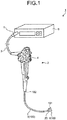
- FIG. 1 is a diagram schematically illustrating an entire structure of an inspection system according to a first embodiment of the present invention.
- An inspection system 1 illustrated in FIG. 1 includes an endoscope 2 and an inspection device 6.
- the endoscope 2 includes a transmission cable 3, an operating unit 4, and a connector portion 5.
- the endoscope 2 captures an in-vivo image of a subject by inserting an inserting portion 100 that is a part of the transmission cable 3 into a body cavity of the subject, and outputs an imaging signal (image data) to the inspection device 6 or a processor (image processing device) described later.
- the endoscope 2 includes: an imaging unit 20 (imaging device) that captures an in-vivo image and is located on one end of the transmission cable 3, that is, a distal end 101 side of the inserting portion 100 to be inserted into a body cavity of a subject; and an operating unit 4 that is located on a proximal end 102 side of the inserting portion 100 and receives various kinds of operation for the endoscope 2.
- an imaging unit 20 imaging device
- an operating unit 4 that is located on a proximal end 102 side of the inserting portion 100 and receives various kinds of operation for the endoscope 2.
- the imaging unit 20 is connected to the connector portion 5 via the operating unit 4 by the transmission cable 3. Image data captured by the imaging unit 20 is output to the connector portion 5 via the transmission cable 3 having a length of several meters, for example. Furthermore, a light shielding cap A100 is detachably provided at the distal end 101. The light shielding cap A100 is used when the endoscope 2 generates a dark-time image.
- the dark-time image is an image (image data) generated without light receiving by an imaging element of the imaging unit 20 described later.
- the connector portion 5 is connected to the inspection device 6 or the processor described later, applies predetermined signal processing to an imaging signal output from the imaging unit 20, also applies A/D conversion to the imaging signal to convert the same from an analog signal to a digital signal, and outputs the digital signal to the inspection device 6 or the processor.
- the inspection device 6 calculates a correction amount and a coefficient in order to correct lateral streak noise included in an imaging signal generated by the endoscope 2, and records these calculation results in the endoscope 2.
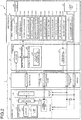
- FIG. 2 is a block diagram illustrating functions of a main portion of the inspection system 1. Details of respective components of the inspection system 1 and a channel of an electric signal inside the inspection system will be described with reference to FIG. 2 .
- the endoscope 2 includes the imaging unit 20, transmission cable 3, and connector portion 5.
- the imaging unit 20 includes a first chip 21 (imaging element) and a second chip 22.
- the first chip 21 includes: a light receiving unit 23 having a plurality of unit pixels 230 that is arranged in a two-dimensional matrix in a matrix direction, each receives light from the outside, and each generates and outputs an imaging signal in accordance with a received light amount, and a plurality of dummy pixels 247 that is provided in each vertical line in arrangement of the plurality of unit pixels 230 and each generates and outputs a dummy signal to be used in correction processing for an imaging signal; a reading unit 24 that reads an imaging signal and a dummy signal photoelectrically converted in the light receiving unit 23; and a timing generation unit 25 that generates a timing signal based on a reference clock signal and a synchronization signal received from the connector portion 5, and outputs the generated timing signal to the reading unit 24.
- a light receiving unit 23 having a plurality of unit pixels 230 that is arranged in a two-dimensional matrix in a matrix direction, each receives light from the outside, and each generates and outputs an imaging signal in accordance
- the second chip 22 has a buffer 27 that functions as a transmission unit to transmit an imaging signal output from the first chip 21 to the inspection device 6 or the processor described later via the transmission cable 3 and the connector portion 5. Note that combination of circuits mounted on the first chip 21 and the second chip 22 can be suitably changed in accordance with setting convenience.
- the imaging unit 20 receives, together with ground GND, power supply voltage VDD generated by a power supply unit 61 inside the inspection device 6 or a power supply unit of the processor described later via the transmission cable 3.
- a capacitor C1 for power supply stabilization is provided between the power supply voltage VDD and the ground GND which are supplied to the imaging unit 20.
- the connector portion 5 includes an analog front end unit 51 (hereinafter referred to as "AFE unit 51"), an imaging signal processing unit 52, a connector recording unit 53, and a drive signal generation unit 54.
- the connector portion 5 electrically connects the endoscope 2 (imaging unit 20) to a processor 9 and functions as a relay processing unit to relay an electric signal.
- the connector portion 5 and the imaging unit 20 are connected by the transmission cable 3, and the connector portion 5 and the processor 9 are connected by, for example, a coil cable.
- the AFE unit 51 receives an imaging signal output from the imaging unit 20 via the transmission cable 3, performs impedance matching with a passive element such as a resistance, and extracts an AC component at a capacitor, and then determines an operating point in a voltage-dividing resistance. After that, the AFE unit 51 applies analog-digital (A/D) conversion to an analog imaging signal, and transmits the converted signal to the imaging signal processing unit 52 as a digital imaging signal.
- A/D analog-digital
- the imaging signal processing unit 52 is formed of, for example, a field programmable gate array (FPGA), and generates a reference clock signal (e.g., a clock signal of 27 MHz) to be a reference of operation in respective components of the endoscope 2, and a synchronization signal indicating a start position of each frame, supplies the generated signals to the timing generation unit 25, applies predetermined signal processing such as noise removal to a digital imaging signal received from the AFE unit 51, and outputs the same to inspection device 6 or the processor described later.
- FPGA field programmable gate array
- the connector recording unit 53 is formed by using a flash memory, a random access memory (RAM), or the like, and temporarily records: various kinds of information to drive the endoscope 2; and parameters in processing. Furthermore, the connector recording unit 53 includes an eigenvalue information recording unit 531 to record an eigenvalue calculated by the inspection device 6 described later and used in correcting lateral streak noise.
- the drive signal generation unit 54 generates a synchronization signal indicating a start position of each frame based on a reference clock signal (e.g., clock signal of 27 MHz) that is supplied from the inspection device 6 and serves as a reference of operation in respective components of the endoscope 2, and outputs the synchronization signal together with the reference clock signal to the timing generation unit 25 of the imaging unit 20 via the transmission cable 3.
- a reference clock signal e.g., clock signal of 27 MHz
- the synchronization signal generated by the drive signal generation unit 54 includes a horizontal synchronization signal and a vertical synchronization signal.
- the inspection device 6 includes a power supply unit 61, a clock generation unit 62, a recording unit 63, and an image processing unit 64.
- the power supply unit 61 generates power supply voltage VDD and supplies the generated power supply voltage VDD to the imaging unit 20 together with ground GND via the connector portion 5 and the transmission cable 3.
- the clock generation unit 62 generates a reference clock signal and outputs the generated reference clock signal to the drive signal generation unit 54.
- the recording unit 63 is formed by using a flash memory, a random access memory (RAM), or the like, and temporarily records: various kinds of information to drive the inspection device 6; and parameters in processing. Additionally, the recording unit 63 sequentially records an imaging signal generated by the imaging unit 20 of the endoscope 2.
- RAM random access memory
- the image processing unit 64 includes an acquisition unit 641, a first generation unit 642, a fourth calculation unit 643, a clamp processing unit 644, a second generation unit 645, a first calculation unit 646, a second calculation unit 647, a third calculation unit 648, a recording control unit 649, and an imaging control unit 650.
- the acquisition unit 641 acquires, from the imaging unit 20, a plurality of pieces of dark-time image data generated by the imaging unit 20 of the endoscope 2 via the connector portion 5 of the endoscope 2 in state that the imaging unit (imaging element) 20 is shielded from light.
- the first generation unit 642 adds up the plurality of pieces of dark-time image data acquired by the acquisition unit 641, and generates average added image data by dividing the added-up data by the number of frames of the dark-time image data. Specifically, the first generation unit 642 adds up all of the plurality of pieces of dark-time image data acquired by the acquisition unit 641 and generates the average added image data by dividing an added-up result by the number of frames of the dark-time image data.
- the fourth calculation unit 643 calculates, for each horizontal line, a clamp value in order to correct an imaging signal of each of the plurality of unit pixels 230 based on a correlation degree between the plurality of dummy pixels 247 and the plurality of unit pixels 230 in each horizontal line. Specifically, the fourth calculation unit 643 adds weights to the plurality of dummy pixels 247 in each horizontal line based on the correlation degree with the plurality of unit pixels 230, and calculates, for each horizontal line, a clamp value in order to correct an imaging signal of each of the plurality of unit pixels 230.
- the fourth calculation unit 643 includes a fifth calculation unit 643a, a sixth calculation unit 643b, and a seventh calculation unit 643c.
- the fifth calculation unit 643a calculates, for each frame, an average value of dummy signals respectively output from the plurality of dummy pixels 247 in a dark-time image corresponding to dark-time image data acquired by the acquisition unit 641.
- the sixth calculation unit 643b calculates an average value of dummy signals respectively output from the plurality of dummy pixels 247 in a range of horizontal lines which include a horizontal line to be corrected in the dark-time image corresponding to the dark-time image data acquired by the acquisition unit 641 and are located in a vertical direction while setting the horizontal line as a reference.
- the seventh calculation unit 643c calculates a clamp value based on; a horizontal line to be corrected; a range of horizontal lines; an average value of dummy signals respectively output from a plurality of dummy pixels 247 in a dark-time image; an average value of dummy signals respectively output from the plurality of dummy pixels 247 in the range of horizontal lines; and a coefficient indicating a correlation degree.
- the seventh calculation unit 643c calculates a clamp value based on: a horizontal line to be corrected, a range of horizontal lines; an average value of dummy signals respectively output from a plurality of dummy pixels 247 in a dark-time image; an average value of dummy signals respectively output from the plurality of dummy pixels 247 in the range of horizontal lines; and weighting in accordance with a coefficient indicating a correlation degree.
- the clamp processing unit 644 performs, for each horizontal line, clamp processing to subtract a clamp value calculated by the fourth calculation unit 643 from an imaging signal of each of the plurality of unit pixels 230.
- the second generation unit 645 generates, for each frame, difference image data obtained by subtracting average added image data generated by the first generation unit 642 from image data corrected by weighting based on a correlation degree between a plurality of dummy pixels 247 and a plurality of unit pixels 230 in each horizontal line of the imaging unit 20. Specifically, the second generation unit 645 generates, for each frame, difference image data by subtracting average added image data generated by the first generation unit 642 from image data subjected to the clamp processing by the clamp processing unit 644.
- the correlation degree represents a difference between a dummy signal output from each of the plurality of dummy pixels 247 and an imaging signal output from each of the plurality of unit pixels 230 in each horizontal line.
- the first calculation unit 646 calculates, as a lateral streak noise index, a statistical value of difference image data in each frame generated by the second generation unit 645. Specifically, the first calculation unit 646 calculates any one of an average value, a median value, a maximum value, a minimum value, and a mode of imaging signals in each horizontal line of a difference image corresponding to difference image data generated by the second generation unit 645. Note that a description will be provided below assuming that the first calculation unit 646 calculates an average value of imaging signals in each horizontal line of a difference image corresponding to difference image data generated by the second generation unit 645.
- the second calculation unit 647 calculates, for each correlation degree between the plurality of dummy pixels 247 and the plurality of unit pixels 230 in each horizontal line of the imaging unit 20, a plurality of lateral streak noise indices calculated by the first calculation unit 646 for each frame. Specifically, the second calculation unit 647 calculates, as a lateral streak noise index for each frame, a statistical value based on an average value of imaging signals calculated by the first calculation unit 646 for each horizontal line.
- the third calculation unit 648 calculates, as a correction value to correct lateral streak noise included in image data, a correlation degree between the plurality of dummy pixels 247 and the plurality of unit pixels 230 in each horizontal line of the imaging unit 20, in which the correlation degree has a minimum value among the plurality of lateral streak noise indices calculated by the second calculation unit 647 for each correlation degree between the plurality of dummy pixels 247 and the plurality of unit pixels 230 in each horizontal line of the imaging unit 20.
- the recording control unit 649 records the correction value calculated by the third calculation unit 648 in the eigenvalue information recording unit 531 of the connector recording unit 53 in the endoscope 2.
- the imaging control unit 650 controls imaging operation of the endoscope 2 connected to the inspection device 6. Specifically, the imaging control unit 650 causes the endoscope 2 connected to the inspection device 6 to start imaging at a predetermined frame rate.
- FIG. 3 is a block diagram illustrating the detailed configuration of the first chip illustrated in FIG. 2 .
- FIG. 4 is a circuit diagram illustrating a configuration of the first chip 21.
- the first chip 21 includes the light receiving unit 23, the reading unit 24 (driving unit), the timing generation unit 25, a hysteresis unit 28, and an output unit 31 (amplifier).
- the hysteresis unit 28 shapes waveforms of a reference clock signal and a synchronization signal received via the transmission cable 3 and outputs, to the timing generation unit 25, the reference clock signal and the synchronization signal subjected to the waveform shaping.
- the timing generation unit 25 generates various kinds of drive signals based on the reference clock signal and the synchronization signal received from the hysteresis unit 28, and outputs the drive signals respectively to a vertical scanning unit 241 (row selection circuit), a noise removal unit 243, and a horizontal scanning unit 245 of the reading unit 24 described later.
- the reading unit 24 transfers, to the output unit 31, an imaging signal output from each of the plurality of pixels of the light receiving unit 23 described later and a reference signal output from a reference voltage generation unit 246.
- the reading unit 24 includes the vertical scanning unit 241 (row selection circuit), a constant current source 242, the noise removal unit 243 (noise removal circuit), a column source follower transistor 244, the horizontal scanning unit 245, and the reference voltage generation unit 246.
- the noise removal unit 243 removes non-uniform output of the respective unit pixels 230 and the noise signal at the time of pixel resetting, and outputs an imaging signal photoelectrically converted in each of the unit pixels 230. Note that details of the noise removal unit 243 will be described later.
- the horizontal transfer line 258 functions as a transfer unit that transfers an imaging signal output from each of the unit pixels 230.
- each of the unit pixels 230 includes: a photoelectric conversion element 231 (photodiode), a charge converter 233, a transfer transistor 234 (first transfer unit), a pixel reset unit 236 (transistor), a pixel source follower transistor 237, and a dummy pixel 247 (reference signal generation unit).
- a photoelectric conversion element 231 photodiode
- a charge converter 233 charge converter
- a transfer transistor 234 first transfer unit
- a pixel reset unit 236 transistor
- a pixel source follower transistor 237 a dummy pixel 247
- a unit cell includes a set formed of one or a plurality of photoelectric conversion elements and a transfer transistor, and one unit cell is included in each of the unit pixels 230.
- the photoelectric conversion element 231 photoelectrically converts incident light into a signal charge amount in accordance with a light amount, and accumulates the signal charge.
- Each of the photoelectric conversion element 231 has a cathode connected to one end of the transfer transistor 234 and an anode connected to the ground GND.
- the charge converter 233 is formed of a floating diffusion capacitance (FD), and converts the charge accumulated in the photoelectric conversion element 231 into voltage.
- FD floating diffusion capacitance
- the transfer transistor 234 transfers the signal charge from the photoelectric conversion element 231 to the charge converter 233.
- the transfer transistor 234 has a gate connected to a signal line supplied with a drive signal (row selection pulse) ⁇ R and a drive signal ⁇ T, and the other end connected to the charge converter 233.
- a drive signal row selection pulse
- ⁇ T drive signal
- the pixel reset unit 236 resets the charge converter 233 to a predetermined potential.
- the pixel reset unit 236 has one end connected to power supply voltage VR, and the other end connected to the charge converter 233, and a gate connected to a signal line supplied with the drive signal ⁇ R.
- the drive signal ⁇ R is supplied from the vertical scanning unit 241 via the signal line, the pixel reset unit 236 is turned on, releases the signal charge accumulated in the charge converter 233, and resets the charge converter 233 to the predetermined potential.
- the pixel source follower transistor 237 has one end connected to the power supply voltage VR, the other end connected to the vertical transfer line 239, and a gate in which a signal (imaging signal or signal at the time of resetting) converted to voltage by the charge converter 233 is received.
- a signal imaging signal or signal at the time of resetting
- charge is read from the photoelectric conversion element 231 and converted to voltage by the charge converter 233, and the pixel source follower transistor 237 has the charge transferred to the vertical transfer line 239.
- a plurality of dummy pixels 247 is provided in each horizontal line of unit pixels 230. Note that, in FIG. 4 , an example in which one dummy pixel 247 is provided in each horizontal line is illustrated to simplify the description, but not limited thereto, the number of dummy pixels 247 can be suitably changed.
- Each of the dummy pixels 247 includes a pixel reset unit 236a and a pixel source follower transistor 237a. In other words, the dummy pixel 247 has a configuration omitting, from the unit pixel 230, the photoelectric conversion element 231 (photodiode), the charge converter 233, and the transfer transistor 234 (first transfer unit).
- the pixel reset unit 236a fixes the gate of the pixel source follower transistor 237a at a predetermined potential.
- the pixel reset unit 236a has one end connected to the power supply voltage VR, the other end connected to the gate of the pixel source follower transistor 237a, and a gate connected to a signal line supplied with the drive signal ⁇ T and the drive signal ⁇ R.
- the pixel reset unit 236a When the drive signal ⁇ R is supplied from the timing generation unit 25 to the gate of the pixel reset unit 236a via the signal line, the pixel reset unit 236a is turned on, and the gate of the pixel source follower transistor 237a is fixed at the predetermined potential (VR) .
- the pixel source follower transistor 237a has one end connected to the power supply voltage VR supplied from the reference voltage generation unit 246 (reference voltage generation unit 246a illustrated in FIG. 5A ), the other end connected to the vertical transfer line 239, and a gate in which the predetermined potential (VR) is received.
- the pixel source follower transistor 237a thus configured, when selecting operation described later is performed, a dummy signal (equivalent to an OB signal) according to the predetermined potential VR is transferred to the vertical transfer line 239 via the pixel source follower transistor 237a.
- the drive signal ⁇ R is supplied to the gate of the pixel reset unit 236a when the power supply voltage VR is applied at a level of the power supply voltage VDD (e.g., 3.3 V) and VR (e.g., 2 V)
- VDD power supply voltage
- VR e.g., 2 V
- the pixel source follower transistor 237a is turned on, and the dummy pixel 247 including the pixel reset unit 236a is selected (selecting operation).
- the drive signal ⁇ R is supplied to the gate of the pixel reset unit 236a when the power supply voltage VR is applied at a non-selection voltage level (e.g., 1 V) and VR (e.g., 1 V), the pixel source follower transistor 237a is turned off, and selection of the dummy pixel 247 including the pixel reset unit 236a is canceled (non-selecting operation).
- a non-selection voltage level e.g. 1 V
- VR e.g. 1 V
- the constant current source 242 has one end connected to the vertical transfer line 239, the other end connected to the ground GND, and a gate applied with bias voltage Vbias1.
- the constant current source 242 drives the unit pixel 230 with the constant current source 242, and reads output of the unit pixel 230 to the vertical transfer line 239.
- a signal read to the vertical transfer line 239 is received in the noise removal unit 243.
- the noise removal unit 243 includes a transfer capacitance 252 (AC coupling capacitor) and a clamp switch 253 (transistor).
- the transfer capacitance 252 has one end connected to the vertical transfer line 239 and the other end connected to the column source follower transistor 244.
- the clamp switch 253 has one end connected to a signal line supplied with clamp voltage Vclp from the reference voltage generation unit 246.
- the clamp switch 253 has the other end connected between the transfer capacitance 252 and the column source follower transistor 244, and has a gate in which a drive signal ⁇ VCL is received from the timing generation unit 25.
- An imaging signal received in the noise removal unit 243 is an optical noise sum signal including a noise component.
- the transfer capacitance (AC coupling capacitor) 252 is only to have a sufficient capacitance for a receiving capacitance of the column source follower transistor 244. Furthermore, an area occupied by the noise removal unit 243 can be reduced in the first chip 21 because a sampling capacitance can be omitted.
- the column source follower transistor 244 has one end connected to the power supply voltage VDD, the other end connected to one end of a column selection switch 254 (second transfer unit), and the gate in which an imaging signal having noise removed by the noise removal unit 243 is received.
- the column selection switch 254 has one end connected to the other end of the column source follower transistor 244, has the other end connected to the horizontal transfer line 258 (second transfer line), and has a gate connected to a signal line to be supplied a drive signal ⁇ HCLK ⁇ M> from the horizontal scanning unit 245.
- the drive signal ⁇ HCLK ⁇ M> is supplied from the horizontal scanning unit 245 to the gate of the column selection switch 254 of a column ⁇ M>, the column selection switch 254 is turned on, and transfers a signal of the vertical transfer line 239 in the column ⁇ M> (an imaging signal having noise removed by the noise removal unit 243) to the horizontal transfer line 258.
- a horizontal reset transistor 256 has one end connected to the ground GND, the other connected to the horizontal transfer line 258, and a gate in which a drive signal ⁇ HCLR is received from the timing generation unit 25.
- the horizontal reset transistor 256 is turned on and resets the horizontal transfer line 258.
- a constant current source 257 has one end connected to the horizontal transfer line 258, the other end connected to the ground GND, and a gate applied with bias voltage Vbias2.
- the constant current source 257 reads an imaging signal from the vertical transfer line 239 to the horizontal transfer line 258.
- the imaging signal or a dummy signal read to the horizontal transfer line 258 is received in the output unit 31.
- the output unit 31 amplifies and outputs an imaging signal having noise removed and a dummy signal (reference signal to be a reference at the time of correcting a lateral line) as needed (Vout).
- crosstalk of an imaging signal in a column direction can be suppressed by alternately performing reading of an imaging signal after noise removal from the vertical transfer line 239 and resetting of the horizontal transfer line 258 by the horizontal reset transistor 256.
- a dummy signal and an imaging signal are transmitted to the connector portion 5 via the transmission cable 3.
- FIGS. 5A and 5B are circuit diagrams illustrating configurations of the reference voltage generation unit 246 of the light receiving unit 23 of the endoscope 2 according to the first embodiment.
- a reference voltage generation unit 246a illustrated in FIG. 5A includes: a resistance voltage dividing circuit including two resistances 291 and 292; and a multiplexer 293 driven by a drive signal ⁇ VRSEL.
- the multiplexer 293 alternately switches the power supply voltage VDD (e.g., 3.3 V) and non-selection voltage Vfd_L (e.g., 1 V) generated at the resistance voltage dividing circuit in accordance with the drive signal ⁇ VRSEL received from the timing generation unit 25, and applies the voltage to all of the pixels and the dummy pixels 247 as the power supply voltage VR.
- VDD power supply voltage
- Vfd_L non-selection voltage
- a reference voltage generation unit 246b illustrated in FIG. 5B includes: a resistance voltage dividing circuit including two resistances 291 and 292; and a switch (transistor) 294 driven by a drive signal ⁇ VSH.
- the reference voltage generation unit 246b generates clamp voltage Vclp of the noise removal unit 243 at the timing when the drive signal ⁇ VSH is driven by driving of the switch 294.
- FIG. 6A is a view schematically illustrating an outline of the conventional method of correcting lateral streak noise.
- FIG. 6B is a view illustrating an exemplary image corrected by the conventional method of correcting lateral streak noise.
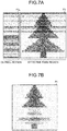
- FIG. 7A is a view schematically illustrating a case where lateral streak noise cannot be corrected by the conventional method of correcting lateral streak noise.
- FIG. 7B is a view illustrating an exemplary image in a case where lateral streak noise cannot be corrected by the conventional method of correcting lateral streak noise. Note that, in FIG. 7A , it is assumed that lateral streak noise is uniformly generated in an entire portion of each row on an upper half of the image, and lateral streak noise is generated only in OB pixels in a lower half of the image.
- an average value of respective signal values of a plurality of OB pixels P1 B in each horizontal line is defined as a clamp value, and this clamp value is subtracted from an imaging signal output from a pixel P1 i of the same horizontal line in an effective pixel region not shielded from light.
- a high-quality pixel P2 having lateral streak noise corrected can be obtained.
- a low-quality image P4 is obtained as illustrated in FIG. 7B because lateral streak noise can be normally corrected in the upper half while lateral streak noise is abnormally corrected in the lower half.
- a state that may possibly happen is that: rows illustrated in the upper half and rows illustrated in the lower half are generated randomly within one image as illustrated in FIG. 7A .
- the inspection device 6 calculates a clamp value for each first chip 21 (imaging element), and records the calculated clamp value in the connector recording unit 53 of the endoscope 2.
- FIG. 8A is a view schematically illustrating a dark-time image corresponding to dark-time image data generated by the imaging unit 20.
- FIG. 8B is a view schematically illustrating a corrected image in which lateral streak noise included in dark-time image data is corrected.
- FIG. 8C is a view schematically illustrating an average value of pixel values in each row of the imaging unit 20.
- the inspection device 6 calculates, based on dark-time image data generated by the imaging unit 20, a correction value (fixed value) including an optimal range of horizontal lines and a constant in order to correct lateral streak noise included in image data generated by the imaging unit 20.
- a correction value fixed value
- the inspection device 6 calculates a clamp value at the time of correcting a pixel value of an effective pixel P5 i in each row by: vertically expanding a calculation range relative to a horizontal line to be corrected to increase the number of horizontal lines in the range; subtracting an average value of pixel values of dummy pixels P5 B from a clamp value of each horizontal line; multiplying this subtraction calculation result by a coefficient (e.g., 0, 0.1, 0.2, ⁇ , 1.0); and adding the average value of the pixel values of the dummy pixels P5 B again (processing 1).
- a coefficient e.g., 0, 0.1, 0.2, ⁇ , 1.0
- the inspection device 6 After that, the inspection device 6 generates a corrected image P5 ave (refer to FIG. 8B ) in which lateral streak noise included in the image data of the effective pixel P5 i is corrected by subtracting the clamp value of the corresponding horizontal line from a pixel value in each row of an effective pixels P5 i in each row (processing 2) .
- the inspection device 6 calculates, as a lateral streak noise index, an average value P5 clp (refer to FIG. 8C ) of pixel values in each horizontal line (processing 3) for the corrected image P5 ave .
- the inspection device 6 calculates a plurality of lateral streak noise indices by sequentially performing the above-described processing 1 to 3 while changing a horizontal line to be corrected, a range of horizontal lines including a horizontal line to be corrected, and a coefficient, and then calculates a statistical value based on the plurality of calculated lateral streak noise indices, thereby calculating, as an eigenvalue (correction value), an optimal range of horizontal lines and an optimal coefficient in order to correct lateral streak noise included in image data generated by the imaging unit 20 (processing 4).
- the inspection device 6 calculates a plurality of lateral streak noise indices by sequentially performing the above-described processing 1 to 3 while changing a horizontal line to be corrected, a range of horizontal lines including a horizontal line to be corrected, and a coefficient, and calculates a standard deviation of the plurality of calculated lateral streak noise indices, and then calculates, as a correction value (fixed value), a range of horizontal lines (number of rows) and a coefficient in which the standard deviation becomes minimum. Meanwhile, the inspection device 6 uses the standard deviation as a statistical value, but may also use any one of a weighted average value, a mode, a median value, a maximum value, and a minimum value, for example.
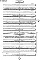
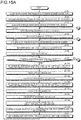
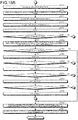
- FIGS. 9A and 9B are flowcharts illustrating an outline of processing executed by the inspection device 6 to calculate an eigenvalue of the imaging unit 20.
- the imaging control unit 650 first causes the endoscope 2 to start imaging dark-time image data at a predetermined frame rate (e.g., 30 fps) (step S101).
- a predetermined frame rate e.g. 30 fps
- the acquisition unit 641 acquires, from the endoscope 2, pieces of dark-time image data of all of frames (e.g., 256 frames) generated by the imaging unit 20 of the endoscope 2, and records the acquired pieces of dark-time image data in the recording unit 63 (step S102).
- pieces of dark-time image data of all of frames e.g., 256 frames
- the first generation unit 642 acquires the pieces of dark-time image data of all of the frames recorded in the recording unit 63, adds up pixel values in an effective pixel region of the acquired pieces of dark-time image data of all of the frames, and then generates average added image data by dividing the added-up pixel value by the number of frames (step S103).
- the image processing unit 64 acquires dark-time image data corresponding to a frame number from the recording unit 63 (step S106), and sets a horizontal line to be corrected as a first row (step S107).
- the fifth calculation unit 643a extracts pixel values of dummy pixels of the dark-time image data acquired from the recording unit 63, and calculates an average value AVE_ob of the extracted pixel values of the dummy pixels (step S108). Specifically, as illustrated in FIG. 10 , after extracting respective pixel values of all of dummy pixels in a range B1 of a dark-time image P10 acquired from the recording unit 63, the fifth calculation unit 643a calculates an average value AVE_ob by adding up the extracted pixel values of all of the respective dummy pixels and then dividing the added-up pixel value by the number of strokes of all of the dummy pixels.
- step S109: Yes the inspection device 6 proceeds to step S115 described later.
- step S109: No the inspection device 6 proceeds to step S110 described later.
- step S110 the fourth calculation unit 643 sets a range B2 of horizontal lines such that the total number of horizontal lines becomes m while centering a horizontal line to be corrected.
- the sixth calculation unit 643b calculates a clamp value CLP_temp(n, m) by adding up the extracted pixel values of the dummy pixels 247 in the range of horizontal lines, and dividing the added-up pixel value by the number of pixels of the dummy pixels 247 in the range of horizontal lines (step S111). Specifically, as illustrated in FIG.
- the sixth calculation unit 643b calculates the clamp value CLP_temp(n, m) by adding up the extracted pixel values of the dummy pixels 247 in the range m of horizontal lines, and dividing the added pixel value by the number of the dummy pixels 247 in the range m of horizontal lines. Note that n represents the number of horizontal lines (target rows) to be corrected.
- the seventh calculation unit 643c calculates a clamp value CLP_a(n) (step S112). Specifically, the seventh calculation unit 643c calculates the clamp value CLP_a(n) by Expression (1) below in a case where: a horizontal line to be corrected is defined as n, a range of horizontal lines is defined as m, an average value of dummy signals respectively output from one or a plurality of correction pixels in a dark-time image is defined as AVE_ob, an average value of dummy signals respectively output from one or a plurality of correction pixels in the range m of horizontal lines is defined as CLP_temp(n, m), and a coefficient indicating a correlation degree between a plurality of dummy pixels 247 and a plurality of unit pixels 230 in each horizontal line is defined as k.
- CLP _ a n CLP _ temp n , m ⁇ AVE _ ob ⁇ k + AVE _ ob
- k satisfies a
- the clamp processing unit 644 subtracts, from a pixel value of a unit pixel 230 in a horizontal line to be corrected, the clamp value CLP_a(n) calculated by the seventh calculation unit 643c in step S112 (step S113) .
- the clamp processing unit 644 applies, to a pixel value of a unit pixel 230 in a horizontal line A1 to be corrected, clamp processing to subtract the clamp value CLP_a(n) calculated by the seventh calculation unit 643c, and records a result of the clamp processing in the recording unit 63.
- the fourth calculation unit 643 sets a subsequent row as a horizontal line to be corrected (step S114), and the processing returns to the above-described step S109.
- step S115 the second generation unit 645 generates difference image data. Specifically, the second generation unit 645 generates the difference image data by subtracting, from dark-time image data corresponding to a frame number, the average added image data calculated by the first generation unit 642 in the above-described step S103.
- the first calculation unit 646 calculates average value data in a range of horizontal lines within one frame (step S116). Specifically, the first calculation unit 646 calculates an average value in each horizontal line in the difference image data generated by the second generation unit 645 in step S115, and calculates average value data for horizontal lines (for number of rows) within one frame by dividing this calculation result by the number of horizontal lines (number of rows) of the difference image data. Meanwhile, the first calculation unit 646 calculates average value data in a range of horizontal lines within one frame, but not limited to thereto, may also calculate any one of a standard deviation, a median value, a mode, a weighted average value, a maximum value, and a minimum value, for example.
- the second calculation unit 647 calculates a lateral streak noise index (step S117). Specifically, the second calculation unit 647 calculates the lateral streak noise index based on the average value data in the range of horizontal lines calculated by the first calculation unit 646 in the above-described step S116. For example, the second calculation unit 647 calculates, as a lateral streak noise index of a current frame, any one of a standard deviation, a median value, a mode, a weighted average value, a maximum value, and a minimum value of the average value data in the range of horizontal lines calculated by the first calculation unit 646. Meanwhile, in the first embodiment, the second calculation unit 647 calculates, as a lateral streak noise index, a standard deviation of average value data in a range of horizontal lines calculated by the first calculation unit 646.
- the second calculation unit 647 records, in the recording unit 63, the calculation result in step S117 (step S118).
- step S120: Yes the inspection device 6 proceeds to step S121 described later.
- step S120: No the inspection device 6 returns to the above-described step S106.
- the third calculation unit 648 calculates a lateral streak noise index A. Specifically, the third calculation unit 648 calculates the lateral streak noise index A based on lateral streak noise in all of frames. For example, the third calculation unit 648 calculates an average value of lateral streak noise indices in all of the frames and newly calculates the average value as a lateral streak noise index A(m, k) corresponding to a range m and a coefficient k.
- step S123: Yes the inspection device 6 proceeds to step S124 described later.
- step S123: No the inspection device 6 returns to the above-described step S106.
- a value to be added to the range m can be suitably changed, and may also be 1, 3, or the like, for example.
- step S126: Yes the inspection device 6 proceeds to step S127 described later.
- step S126: No the inspection device 6 returns to step S106.
- step S127 the third calculation unit 648 calculates a minimum value among all of the lateral streak noise indices A corresponding to all of ranges m and coefficients k recorded in the recording unit 63.
- the recording control unit 649 records, as an eigenvalue (correction value) of the imaging unit 20, a range m of horizontal lines including a horizontal line to be corrected and a coefficient k in the eigenvalue information recording unit 531 of the connector recording unit 53 of the endoscope 2, and here, the range m and coefficient k correspond to the lateral streak noise index having the minimum value calculated by the third calculation unit 648 (step S128).
- the inspection device 6 finishes the present processing.
- the inspection device 6 calculates a correction value of the imaging unit 20 used in correcting lateral streak noise included in image data generated by the imaging unit 20, and records the calculation result in the eigenvalue information recording unit 531 of the connector recording unit 53 of the endoscope 2.
- FIG. 11 is a view schematically illustrating an entire structure of the endoscope system.
- FIG. 12 is a block diagram schematically illustrating a configuration of the endoscope system.
- An endoscope system 1a illustrated in FIGS. 11 and 12 includes an endoscope 2 described above, a display device 8, and a processor 9 (image processing device).
- the display device 8 displays an image for an image signal applied with image processing by the processor 9. Additionally, the display device 8 displays various kinds of information related to the endoscope system 1a.
- the display device 8 is formed by using a display panel or the like, such as a liquid crystal or an organic electro luminescence (EL).
- the processor 9 integrally controls the entire endoscope system 1a, is formed by using, for example, a halogen lamp, a white light emitting diode (LED), or the like, and emits illumination light to a subject from a distal end side of the inserting portion 100 of the endoscope 2 via the connector portion 5 and the transmission cable 3.
- the processor 9 includes a power supply unit 61, a clock generation unit 62, and an image processing unit 91. Note that a description of an illumination mechanism inside the processor 9 will be omitted.
- the image processing unit 91 applies, to a digital imaging signal subjected to signal processing by the imaging signal processing unit 52, image processing such as synchronization processing, white balance (WB) adjustment processing, gain adjustment processing, gamma correction processing, digital analog (D/A) conversion processing, and format conversion processing, and converts the signal into an image signal, and then outputs the image signal to the display device 8.
- image processing unit 91 includes an acquisition unit 911, an average value calculation unit 912, a clamp value calculation unit 913, and a correction unit 914.
- the acquisition unit 911 acquires, from the connector recording unit 53 of the connector portion 5 of the endoscope 2 connected to the processor 9: eigenvalue information that includes a correction value to correct lateral streak noise and relates to parameters needed to apply image processing to image data generated by the imaging unit 20; and the image data generated by the imaging unit 20, respectively.
- the correction value includes: a range m of horizontal lines (number of rows) including a horizontal line to be corrected, and located in the vertical direction while setting the horizontal line as a reference; and a coefficient k indicating a correlation degree between a plurality of dummy pixels 247 and a plurality of unit pixels 230 in each horizontal line.
- the average value calculation unit 912 calculates an average value of dummy signals respectively output from the plurality of dummy pixels 247 in the image corresponding to the image data acquired by the acquisition unit 911.
- the clamp value calculation unit 913 calculates, for each horizontal line, a clamp value in order to correct an imaging signal of each of the plurality of unit pixels 230 based on: the average value of dummy signals calculated by the average value calculation unit 912 and respectively output from the plurality of dummy pixels 247; and the range m of horizontal lines and coefficient k of the correction value acquired by the acquisition unit 911.
- the correction unit 914 corrects an imaging signal of each of the plurality of unit pixels 230 in the horizontal line to be corrected based on the clamp value calculated by the clamp value calculation unit 913 for each horizontal line.
- FIG. 13 is a flowchart illustrating an outline of the processing executed by the processor 9.
- the processor 9 first commands the connected endoscope 2 to start imaging at a predetermined frame rate (step S201).
- the processor 9 causes a light source unit (not illustrated) to emit illumination light to the endoscope 2.
- the image processing unit 91 executes lateral streak noise correction processing to correct lateral streak noise included in image data generated by the endoscope 2 (step S202). Note that details of the lateral streak noise correction processing will be described later.
- the image processing unit 91 applies predetermined image processing to the image data having lateral streak noise corrected, and outputs the same to the display device 8 (step S203). For example, the image processing unit 91 applies, to the image data having the lateral streak noise corrected, addition processing to add an offset value of the imaging unit 20, WB adjustment processing to adjust white balance, gain adjustment processing to adjust gain, and the like, and outputs the image data to the display device 8.
- step S204 the processor 9 commands the endoscope 2 to finish imaging (step S205) and finishes the present processing.
- step S204 in a case where the command signal to finish observation on the subject is not received from the operating unit 4 (step S204: No), the processor 9 returns to step S202.
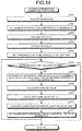
- FIG. 14 is a flowchart illustrating the outline of the lateral streak noise correction processing in FIG. 13 .
- the acquisition unit 911 first acquires a fixed value from the eigenvalue information recording unit 531 of the connector recording unit 53 in the endoscope 2 (step S301), and sets a range m of a horizontal line to be corrected and a coefficient k as the eigenvalue (correction value) (step S302).
- the average value calculation unit 912 acquires RAW data generated by the endoscope 2 (step S303), calculates an average value AVE_ob based on pixel values of dummy pixels included in the acquired RAW data (step S304), and sets the horizontal line to be corrected as a first row (step S305). Specifically, the average value calculation unit 912 adds up the pixel values of the dummy pixels included in the RAW data, and calculates the average value AVE_ob by dividing the added-up result by the number of pixels of the dummy pixels.
- step S306: Yes the processor 9 returns to a main routine in FIG. 13 .
- step S306: No the processor 9 proceeds to step S307.
- step S307 the clamp value calculation unit 913 sets a range of horizontal lines (range of rows) such that a total range of horizontal lines becomes m while centering a horizontal line to be corrected.
- the range of horizontal lines is set such that the total number of the horizontal lines becomes m, including a row in a light shielding region.
- the image processing unit 91 sets, as the range of horizontal lines to be corrected, a horizontal line located on a previous stage (upper side) of the horizontal line to be corrected or a horizontal line used to obtain a reference signal and a horizontal line located on a subsequent stage (lower side) of the horizontal line to be corrected.
- the clamp value calculation unit 913 calculates an average value of pixel values of dummy pixels in the range of horizontal lines set in step S307 based on the pixel values of the dummy pixels in the range of horizontal lines set in step S307 (Step S308). Specifically, the clamp value calculation unit 913 calculates the average value of the pixel values of the dummy pixels in the range of horizontal lines set in step S307 by adding up all of the pixel values of the dummy pixels in the range of horizontal lines set in step S307 and then dividing the added-up result by the number of pixels of the dummy pixels.
- the clamp value calculation unit 913 calculates a clamp value CLP_a (step S309). Specifically, the clamp value calculation unit 913 calculates the clamp value CLP_a by using Expression (1) described above, the average value calculated in step S308 described above, the coefficient k, and the average value AVE_ob calculated in step S304 described above.
- the correction unit 914 corrects, based on the clamp value calculated in step S309, pixel values of unit pixels 230 in the horizontal line to be corrected (step S310). Specifically, the correction unit 914 corrects image data in an effective pixel region in the horizontal line to be corrected by subtracting the clamp value CLP_a from a pixel value output from each of the unit pixels 230 in the effective pixel region in the horizontal line to be corrected.
- step S311 the image processing unit 91 sets a subsequent row as a horizontal line to be corrected (step S311). After step S311, the processor 9 returns to the above-described step S306.
- the first calculation unit 646 calculates, as a lateral streak noise index, a statistical value of difference image data for each frame generated by the second generation unit 645
- the second calculation unit 647 calculates, for each of correlation degrees between a plurality of dummy pixels 247 and a plurality of unit pixels 230 in each horizontal line, a plurality of lateral streak noise indices calculated by the first calculation unit 646 for each frame
- the third calculation unit 648 calculates, as a correction value to correct lateral streak noise included in image data, a correlation degree having a minimum value among the plurality of lateral streak noise indices calculated by the second calculation unit 647 for each of correlation degrees
- the recording control unit 649 records the correction value calculated by the third calculation unit 648 in the eigenvalue information recording unit 531 of the connector recording unit 53 in the endoscope 2. Therefore, the lateral streak noise can be corrected with high accuracy in each first chip 21 even in a case where kinds of noise different from each other are generated in an OB
- dummy pixel 247 that generates a dummy signal equivalent to an OB pixel shielded from light since dummy pixel 247 that generates a dummy signal equivalent to an OB pixel shielded from light is used, lateral streak noise can be corrected with high accuracy in each first chip 21 even in a case where an OB pixel needed to calculate a clamp value cannot be arranged in a first chip 21, and therefore, the area of the first chip 21 can be reduced.
- the example in which a dummy pixel 247 that is equivalent to an OB pixel and generates a dummy signal has been described as an example of a correction pixel that outputs a dummy signal, but an OB pixel shielded from light is also applicable.
- the average value calculation unit 912 calculates an average value of dummy signals respectively output from a plurality of dummy pixels 247 in an image corresponding to image data acquired by the acquisition unit
- the clamp value calculation unit 913 calculates, for each horizontal line, a clamp value to correct respective imaging signals of a plurality of unit pixels 230 based on the average value of the dummy signals respectively output from the plurality of dummy pixels 247 calculated by the average value calculation unit 912, a range of horizontal lines in the imaging unit 20, and a coefficient
- the correction unit 914 corrects respective imaging signals of the plurality of unit pixels 230 in a horizontal line to be corrected based on the clamp value calculated by the clamp value calculation unit 913 for each horizontal line. Therefore, even in a case where kinds of noise different from each other are generated in an OB pixel portion and an effective pixel portion respectively due to fluctuation in power supply voltage, lateral streak noise can be corrected with high accuracy in each first chip 21.
- the second embodiment has a configuration similar to that of a first embodiment described above, and processing executed by an inspection device and lateral streak noise correction processing executed by a processor are different.
- processing executed by each of the inspection device and the processor according to the second embodiment will be described. Note that components same as those of an inspection system 1 and the endoscope system 1a according to the above-described first embodiment will be denoted by the same reference signs, and a description thereof will be omitted.
- FIG. 15A and FIG. 15B are flowcharts illustrating an outline of processing executed by the inspection device 6 to calculate an eigenvalue of an imaging unit 20 according to the second embodiment.
- FIG. 16 is a view schematically illustrating a calculating method executed by the inspection device 6 to calculate an eigenvalue of the imaging unit 20 according to the second embodiment.
- the inspection device 6 executes steps S104a, S110a, S111a, S112a, S113a, and S121a to S130a in the second embodiment instead of steps S104, S110, S111, S112, S113, and S121 to S127 of FIG. 9 in the above-described first embodiment.
- steps S112b to S112e are executed in FIG. 15A . Since other processing is similar to that of FIG. 9 , a description thereof will be omitted.
- a fourth calculation unit 643 sets the range m1 of horizontal lines such that the total number of horizontal lines becomes m1 while centering a horizontal line to be corrected.
- a sixth calculation unit 643b extracts pixel values of dummy pixels 247 in the range of horizontal lines set in step S110 from dark-time image data acquired from a recording unit 63, then adds up the extracted pixel values of the dummy pixels 247 in the range of rows, and calculates a clamp value CLP_temp1(n, m1) by dividing the added-up pixel values by the number of the dummy pixels 247 included in the range of horizontal lines (step S111a). As illustrated in FIG.
- the sixth calculation unit 643b adds up the extracted pixel values of the dummy pixels 247 in the range of horizontal lines, and calculates the clamp value CLP_temp1(n, m1) by dividing the added-up pixel value by the number of the dummy pixels 247 in the range m1 of horizontal lines.
- a seventh calculation unit 643c calculates a provisional clamp value CLP_a1(n, m1) (step S112a). Specifically, the seventh calculation unit 643c calculates the provisional clamp value CLP_a1(n, m1) by Expression (2) below.
- CLP _ a 1 n , m 1 CLP _ temp 1 n , m 1 ⁇ AVE _ ob ⁇ k 1 + AVE _ ob ⁇ 2
- k1 satisfies 0 ⁇ k1 ⁇ 1.
- the fourth calculation unit 643 sets a range m2 of horizontal lines such that the total number of horizontal lines becomes m2 while centering the horizontal line to be corrected (step S112b).
- the sixth calculation unit 643b extracts pixel values of dummy pixels 247 in the range of horizontal lines set in step S110 from dark-time image acquired from the recording unit 63, then adds up the extracted pixel values of the dummy pixels 247 in the range of rows, and calculates a clamp value CLP_temp2(n, m2) by dividing the added-up pixel value by the number of pixels of the dummy pixels 247 in the range of horizontal lines (step S112c). Specifically, the sixth calculation unit 643b, as illustrated in FIG.
- the sixth calculation unit 643b extracts pixel values of dummy pixels 247 in a range B3 of the dark-time image P10 corresponding to the range m2 of horizontal lines, then adds up the extracted pixel values of the dummy pixels 247 in the range of rows, and calculates the clamp value CLP_temp2(n, m2) by dividing the added-up pixel value by the number of dummy pixels 247 in the range m2 of horizontal lines.
- the seventh calculation unit 643c calculates a provisional clamp value CLP_a2(n, m2) (step S112d). Specifically, the seventh calculation unit 643c calculates the provisional clamp value CLP_a2(n) by Expression (3) below.
- CLP _ a 2 n , m 2 CLP _ temp 2 n , m 2 ⁇ AVE _ ob ⁇ k 2 + AVE ⁇ ob ⁇ 2
- k2 satisfies 0 ⁇ k2 ⁇ 1.
- the seventh calculation unit 643c calculates a clamp value CLP_a(n) (step S112e). Specifically, the seventh calculation unit 643c calculates the clamp value CLP_a(n) by using the provisional clamps calculated in the respective steps S112a and 112d. More specifically, the seventh calculation unit 643c calculates the clamp value CLP_a(n) by Expression (4) below.
- CLP _ a n CLP _ a 1 n , m 1 + CLP _ a 2 n , m 2
- the clamp processing unit 644 subtracts the clamp value CLP_a(n) calculated by the seventh calculation unit 643c in step S112e from a unit pixel 230 in the horizontal line to be corrected (step S113a). Specifically, as illustrated in FIG. 16 , the clamp processing unit 644 subtracts the clamp value CLP_a(n) from a pixel value of a unit pixel 230 in a horizontal line A1 to be corrected, and records a result in the recording unit 63.
- a third calculation unit 648 calculates a lateral streak noise index A. Specifically, the third calculation unit 648 calculates the lateral streak noise index A based on lateral streak noise in all of frames. For example, the third calculation unit 648 calculates an average value of lateral streak noise of all of frames, and newly calculates the same as lateral streak noise indices A (m1, m2, k1, k2) corresponding to the ranges m1, m2 and the coefficients k1, k2.
- step S122a: Yes the inspection device 6 suspends calculation and recording of the lateral streak noise indices, and proceeds to step S130a.
- step S122a: No the inspection device 6 proceeds to step S123a described later.
- k1 exceeds 1 (k1 > 1) (step S124a: Yes)
- step S124a Yes
- step S125a the inspection device 6 proceeds to step S125a described later.
- step S123a No
- step S106 the inspection device 6 proceeds to the above-described step S106.
- step S126a: Yes the inspection device 6 proceeds to step S127a described later.
- step S126a: No the inspection device 6 proceeds to step S106 described above.
- step S128a: Yes the inspection device 6 proceeds to step S129a described later.
- step S128a: No the inspection device 6 proceeds to the above-described step S106.
- step S129a the inspection device 6 proceeds to step S106 described above.
- a value to be added to the above-mentioned ranges m1, m2 can be suitably changed, and may be 1, 3, or the like, for example.
- step S130a the third calculation unit 648 calculates a minimum value among all of the lateral streak noise indices A corresponding to all of the ranges m1, m2 and the coefficients k1, k2 recorded in the recording unit 63.
- the recording control unit 649 records, as eigenvalues (correction values) of the imaging unit 20, the ranges m1, m2 of horizontal lines including a horizontal line to be corrected and the coefficients k1, k2 in an eigenvalue information recording unit 531 of a connector recording unit 53 of the endoscope 2, in which the ranges m1, m2 and the coefficients k1, k2 correspond to the minimum value calculated by the third calculation unit 648 (step S131).
- the inspection device 6 is finishes the present processing.
- the inspection device 6 calculates a correction value to correct lateral streak noise included in image data generated by the imaging unit 20, and records the same in the eigenvalue information recording unit 531 of the connector recording unit 53 of the endoscope 2.
- FIG. 17 is a flowchart illustrating an outline of the lateral streak noise correction processing executed by the processor 9. Steps 401 to S406 correspond to steps S301 to S306 described above in FIG. 14 , respectively.
- an image processing unit 91 sets a range of horizontal lines (number of rows) such that a total range of horizontal lines becomes m1 while centering a horizontal line to be corrected.
- an average value calculation unit 912 calculates an average value of pixel values of dummy pixels in a range of horizontal lines based on pixel values of dummy pixels in the range of horizontal lines set in step S407 (step S408). Specifically, the average value calculation unit 912 calculates an average value of the pixel values of the dummy pixels in the range of horizontal lines by adding up all of the pixel values of the dummy pixels in the range of horizontal lines and then dividing the added-up result by the number of pixels of the dummy pixels.
- a clamp value calculation unit 913 calculates a provisional clamp value CLP_a1 (step S409). Specifically, the clamp value calculation unit 913 calculates the provisional clamp value CLP_a1 by using Expression (2) described above, the average value calculated by the average value calculation unit 912 in step S408 described above, a coefficient k1, and an average value AVE_ob calculated in step S404.
- the image processing unit 91 sets a range of horizontal lines such that total number of horizontal lines becomes m2 while centering horizontal line to be corrected (step S410).
- the average value calculation unit 912 calculates an average value of pixel values of dummy pixels in the range of horizontal lines based on the pixel values of the dummy pixels in the range of horizontal lines set in step S410 (step S411). Specifically, the average value calculation unit 912 calculates an average value of the pixel values of the dummy pixels in the range of horizontal lines by adding up all of the pixel values of the dummy pixels in the range of horizontal lines and then dividing the added-up result by the number of pixels of the dummy pixels.
- the clamp value calculation unit 913 calculates a provisional clamp value CLP_a2 (step S412). Specifically, the clamp value calculation unit 913 calculates the provisional clamp value CLP_a2 by using Expression (3) described above, the average value calculated in step S411 described above, a coefficient k2, and the average value AVE_ob calculated in the step S404.
- Steps S414 and S415 correspond to steps 310 and S311 described above in FIG. 14 , respectively.
- the first calculation unit 646 calculates, as a lateral streak noise index, a statistical value of difference image data for each frame generated by the second generation unit 645
- the second calculation unit 647 calculates, for each of different correlation degrees between a plurality of dummy pixels 247 and a plurality of unit pixels 230 in each horizontal line, a plurality of lateral streak noise indices calculated by the first calculation unit 646 for each frame
- the third calculation unit 648 calculates, as a correction value to correct lateral streak noise included in image data, a correlation degree in which a lateral streak noise index becomes a minimum value among the plurality of lateral streak noise indices calculated by the second calculation unit 647 for each of the different correlation degrees
- the recording control unit 649 records the correction value calculated by the third calculation unit 648 in the eigenvalue information recording unit 531 of the connector recording unit 53 in the endoscope 2.
- dummy pixel 247 that generates a dummy signal equivalent to an OB pixel shielded from light since dummy pixel 247 that generates a dummy signal equivalent to an OB pixel shielded from light is used, lateral streak noise can be corrected with high accuracy in each first chip 21 even in a case where an OB pixel needed to calculate a clamp value cannot be arranged in a first chip 21, and therefore, the area of the first chip 21 can be reduced.
- the example in which a dummy pixel 247 that is equivalent to an OB pixel and generates a dummy signal has been described as an example of a correction pixel that outputs a dummy signal, but an OB pixel shielded from light is also applicable.
- the average value calculation unit 912 calculates an average value of dummy signals respectively output from a plurality of dummy pixels 247 in an image corresponding to image data acquired by the acquisition unit
- the clamp value calculation unit 913 calculates, for each horizontal line, a clamp value to correct respective imaging signals of a plurality of unit pixels 230 based on the average value of the dummy signals respectively output from the plurality of dummy pixels 247 calculated by the average value calculation unit 912, a range of horizontal lines in the imaging unit 20, and a coefficient
- the correction unit 914 corrects respective imaging signals of the plurality of unit pixels 230 in a horizontal line to be corrected based on the clamp value calculated by the clamp value calculation unit 913 for each horizontal line.
- the coefficient k1 used to correct lateral streak noise satisfies the condition of 0 ⁇ k1 ⁇ 1 and the condition k2 satisfies the condition of 0 ⁇ k2 ⁇ 1, but a following condition (5) may also be satisfied.
- k 1 + k 2 1
- the seventh calculation unit 643c does not need AVE_ob in calculating a clamp value CLP_a(n) because of Expression (7) described above, and therefore, it is not necessary to make the recording unit 63 or the like preliminarily record output (dummy signals) of all of dummy pixels 247 (OB pixels) included in a frame.
- memory capacity of the recording unit 63 can be reduced, and output delay of image data caused by correction processing can be suppressed.
- the image processing unit 64 can practically reduce one parameter from the total number of parameters required for correction processing, the correction processing can be speeded up.
- an image processing unit 64 is provided inside an inspection device 6, but may be provided in a connector portion 5 of an endoscope 2 or an operating unit 4 of the endoscope 2.
- an image processing unit 91 is provided inside a processor 9, but may be provided in the connector portion 5 of an endoscope 2 or an operating unit 4 of the endoscope 2.
- an eigenvalue information recording unit 531 is provided inside the connector portion 5 of the endoscope 2, but may be provided inside a first chip 21 or may be provided inside the operating unit 4.
- an endoscope to be inserted into a subject is applied, but for example, a capsule-shaped endoscope or an imaging device adapted to image a subject may also be applicable.
- the present invention may include various embodiments not disclosed herein, and various kinds of design change and the like can be made within the technical idea specified in the scope of claims.
Landscapes
- Engineering & Computer Science (AREA)
- Life Sciences & Earth Sciences (AREA)
- Health & Medical Sciences (AREA)
- Signal Processing (AREA)
- Physics & Mathematics (AREA)
- Surgery (AREA)
- Multimedia (AREA)
- Optics & Photonics (AREA)
- Radiology & Medical Imaging (AREA)
- Veterinary Medicine (AREA)
- Nuclear Medicine, Radiotherapy & Molecular Imaging (AREA)
- Pathology (AREA)
- Biophysics (AREA)
- Public Health (AREA)
- Biomedical Technology (AREA)
- Heart & Thoracic Surgery (AREA)
- Medical Informatics (AREA)
- Molecular Biology (AREA)
- Animal Behavior & Ethology (AREA)
- General Health & Medical Sciences (AREA)
- Astronomy & Astrophysics (AREA)
- General Physics & Mathematics (AREA)
- Transforming Light Signals Into Electric Signals (AREA)
- Instruments For Viewing The Inside Of Hollow Bodies (AREA)
- Endoscopes (AREA)
- Image Processing (AREA)
Abstract
Description
- The present invention relates to an inspection device, an image processing device, a correction value calculating method, an image processing method, an inspection program, and a correction program, which calculate a correction value to correct lateral streak noise included in image data generated by an imaging element that images a subject.
- In recent years, an imaging device such as a digital camera includes an imaging element such as a complementary metal oxide semiconductor (CMOS) sensor or a charge coupled device (CCD) sensor. In image data generated by such an imaging element, lateral streak noise is generated due to fluctuation in power supply voltage, capturing of a subject with high luminance, or the like. As a method of correcting such lateral streak noise, there is a known technology in which an offset value is calculated by subtracting a reference black level from an average value of output signals in an OB pixel portion formed of a plurality of photodiodes shielded from light, and after that, a correction amount is calculated by multiplying the offset value by a coefficient defined by a structure of an imaging element, and then a signal of an effective pixel portion formed of a plurality of photodiodes not shielded from light is corrected based on the correction amount (refer to Patent Literature 1).
- Patent Literature 1:
JP 2008-67060 A - However, according to above-described
Patent Literature 1, there is a problem in which kinds of noise different from each other are generated in an OB pixel portion and an effective pixel portion due to fluctuation in power supply voltage, and in such a case, lateral streak noise cannot be corrected with high accuracy and image quality may be deteriorated. - The present invention is made in view of the above-described problem, and is directed to providing an inspection device, an image processing device, a correction value calculating method, an image processing method, an inspection program, and a correction program, in which lateral streak noise can be corrected even in a case where kinds of noise different from each other are generated in the OB pixel portion and the effective pixel portion due to fluctuation in power supply voltage.
- To solve the above-described problem and achieve the object, an inspection device according to the present invention for calculating a correction value to correct lateral streak noise included in image data generated by an imaging element that includes: a plurality of effective pixels arranged in a two-dimensional matrix, each receiving light from outside, and generating and outputting an imaging signal in accordance with a received light amount; and one or a plurality of correction pixels provided in each horizontal line in arrangement of the plurality of effective pixels, and generating and outputting a dummy signal used in correction processing for the imaging signal, includes: an acquisition unit configured to acquire, from the imaging element, a plurality of pieces of dark-time image data generated by the imaging element in a state where the imaging element is shielded from light; a first generation unit configured to generate average added image data by adding up the plurality of pieces of dark-time image data acquired by the acquisition unit and dividing the added-up result by number of frames of the dark-time image data; a second generation unit configured to generate, for each frame, difference image data in which the average added image data generated by the first generation unit is subtracted from the image data corrected based on a correlation degree between the plurality of correction pixels and the plurality of effective pixels in each horizontal line; a first calculation unit configured to calculate, as a lateral streak noise index, a statistical value of the difference image data generated by the second generation unit for each frame; a second calculation unit configured to calculate, for each correlation degree, a plurality of the lateral streak noise indices calculated by the first calculation unit for each frame; a third calculation unit configured to calculate, as the correction value, the correlation degree having a minimum value among the plurality of the lateral streak noise indices calculated by the second calculation unit for each correlation degree; and a recording control unit configured to record the correction value calculated by the third calculation unit in a recording unit provided in the imaging element.
- Moreover, the above-described inspection device according to the present invention further includes: a fourth calculation unit configured to calculate, for each horizontal line, a clamp value to correct the imaging signal of each of the plurality of effective pixels based on the correlation degree; and a clamp processing unit configured to perform, for each horizontal line, clamp processing to subtract the clamp value calculated by the fourth calculation unit from the imaging signal of each of the plurality of effective pixels, wherein the second generation unit generates, for each frame, the difference image data by subtracting the average added image data generated by the first generation unit from the image data applied with the clamp processing by the clamp processing unit.
- Moreover, in the above-described inspection device according to the present invention, the first calculation unit calculates, for each horizontal line, an average value of the imaging signals of a difference image corresponding to the difference image data generated by the second generation unit, and the second calculation unit calculates, as the lateral streak noise index for each frame, a statistical value based on the average value of the imaging signals calculated by the first calculation unit for each horizontal line.
- Moreover, in the above-described inspection device according to the present invention, the fourth calculation unit includes: a fifth calculation unit configured to calculate, for each frame, an average value of dummy signals output from the respective correction pixels in dark-time image corresponding to the dark-time image data acquired by the acquisition unit; a sixth calculation unit configured to calculate an average value of dummy signals output from the respective correction pixels in a range of horizontal lines which include a horizontal line to be corrected in the dark-time image corresponding to the dark-time image data acquired by the acquisition unit and are located in vertical direction while setting the horizontal line as a reference; and a seventh calculation unit configured to calculate CLP_a(n) by Expression (1) below in a case where a horizontal line to be corrected is defined as n, the range is defined as m, an average value of dummy signals output from the respective correction pixels of the dark-time image is defined as AVE_ob, an average value of dummy signals output from the respective correction pixels in the range is defined as CLP_temp(n, m), a coefficient indicating the correlation degree is defined as k, and the clamp value is defined as CLP_a(n):

- Moreover, in the above-described inspection device according to the present invention, the fourth calculation unit includes: a fifth calculation unit configured to calculate, for each frame, an average value of dummy signals output from the respective correction pixels in dark-time image corresponding to the dark-time image data acquired by the acquisition unit; a sixth calculation unit configured to calculate an average value of dummy signals output from the respective correction pixels in a range of horizontal lines which include a horizontal line to be corrected in the dark-time image corresponding to the dark-time image data acquired by the acquisition unit and are located in vertical direction while setting the horizontal line as a reference; and a seventh calculation unit configured to calculate CLP_a(n) by Expressions (2) to (4) below in a case where a horizontal line to be corrected is defined as n, the ranges different from each other are defined as m1 and m2, an average value of dummy signals output from the respective correction pixels of the dark-time image is defined as AVE_ob, average values of dummy signals output from the respective correction pixels in the ranges different from each other are defined as CLP_temp1(n, m1) and CLP_temp2(n, m2), coefficients indicating the correlation degrees different from each other are defined as k1 and k2, and the clamp value is defined as CLP_a(n):


- Moreover, in the above-described inspection device according to the present invention, the k1 and k2 satisfy a condition (5) below:

- Moreover, in the above-described inspection device according to the present invention, the correlation degree is a difference between a dummy signal output from each of the plurality of correction pixels and an imaging signal output from each of the plurality of effective pixels in each horizontal line.
- Moreover, in the above-described inspection device according to the present invention, the statistical value is a standard deviation.
- Moreover, in the above-described inspection device according to the present invention, the correction pixel is a dummy pixel equivalent to an OB pixel shielded from light and generating a dummy signal.
- Moreover, in the above-described inspection device according to the present invention, the correction pixel is an OB pixel shielded from light.
- Moreover, in the above-described inspection device according to the present invention, the imaging element is arranged at a distal end of an inserting portion of an endoscope that images a subject, and the recording unit is formed continuous from the inserting portion and arranged inside a connector portion connectable to a processor that applies image processing to the image data.
- Moreover, an image processing device according to the present invention for connecting to an imaging device including: an imaging element including: a plurality of effective pixels arranged in a two-dimensional matrix, each receiving light from outside, and generating and outputting an imaging signal in accordance with a received light amount; and one or a plurality of correction pixels provided in each horizontal line in arrangement of the plurality of effective pixels, and each generating and outputting a dummy signal used in correction processing for the imaging signal; and a recording unit that records a correction value used in correcting lateral streak noise included in image data generated by the imaging element and the correction value including: a range of horizontal lines which include a horizontal line to be corrected and are located in a vertical direction while setting the horizontal line as a reference; and a coefficient indicating a correlation degree between the correction pixel and the plurality of effective pixels in each horizontal line, includes: an acquisition unit configured to acquire, from the recording unit, the correction value and pieces of the image data generated by the imaging element; an average value calculation unit configured to calculate an average value of dummy signals output from the respective correction pixels in an image corresponding to the image data acquired by the acquisition unit; a clamp value calculation unit configured to calculate, for each horizontal line, a clamp value to correct the imaging signal of each of the plurality of effective pixels based on the average value of the dummy signals output from the respective correction pixels and calculated by the average value calculation unit, the range of horizontal lines, and the coefficient; and a correction unit configured to correct the imaging signal of each of the plurality of effective pixels in the horizontal line to be corrected based on the clamp value calculated by the clamp value calculation unit for each horizontal line.
- Moreover, a correction value calculating method according to the present invention is executed by an inspection device that calculates a correction value used in correcting lateral streak noise included in image data generated by an imaging element including: a plurality of effective pixels arranged in a two-dimensional matrix, each receiving light from outside, and generating and outputting an imaging signal in accordance with a received light amount; and one or a plurality of correction pixels provided in each horizontal line in arrangement of the plurality of effective pixels, and generating and outputting a dummy signal used in correction processing for the imaging signal, and the method includes: acquiring, from the imaging element, a plurality of pieces of dark-time image data generated by the imaging element in a state where the imaging element is shielded from light; first generating average added image data by adding up the plurality of pieces of dark-time image data acquired in the acquiring step, and then dividing the added-up result by number of frames of the dark-time image data; secondly generating, for each frame, difference image data in which the average added image data generated in the first generating step is subtracted from the image data corrected based on a correlation degree between the correction pixel and the plurality of effective pixels in each horizontal line; first calculating, as a lateral streak noise index, a statistical value of the difference image data generated for each frame in the second generating step; secondly calculating, for each correlation degree, a plurality of the lateral streak noise indices calculated in the first calculating step for each frame; thirdly calculating, as the correction value, a correlation degree having a minimum value among the plurality of the lateral streak noise indices calculated in the second calculating step for each correlation degree; and performing recording control to record the correction value calculated in the third calculating step in a recording unit provided in the imaging element.
- Moreover, an image processing method according to the present invention is executed by an image processing device connected to an imaging device including: an imaging element including: a plurality of effective pixels arranged in a two-dimensional matrix, each receiving light from outside, and generating and outputting an imaging signal in accordance with a received light amount; and one or a plurality of correction pixels provided in each horizontal line in arrangement of the plurality of effective pixels, and each generating and outputting dummy signal used in correction processing of the imaging signal; and a recording unit that records a correction value used in correcting lateral streak noise included in image data generated by the imaging element, and the correction value including: a range of horizontal lines which include a horizontal line to be corrected and are located in a vertical direction while setting the horizontal line as a reference; and a coefficient indicating a correlation degree between the correction pixel and the plurality of effective pixels in each horizontal line, and the method includes: acquiring, from the recording unit, the correction value and pieces of the image data generated by the imaging element; calculating an average value of dummy signals output from the respective correction pixels in an image corresponding to the image data acquired in the acquiring step; calculating, for each horizontal line, a clamp value to correct the imaging signal of each of the plurality of effective pixels based on the average value of the dummy signals output from the respective correction pixels and calculated in the average value calculating step, the range of horizontal lines, and the coefficient; and correcting the imaging signal of each of the plurality of effective pixels in the horizontal line to be corrected based on the clamp value calculated in the clamp value calculating step for each horizontal line.
- Moreover, an inspection program according to the present invention is for an inspection device that calculates a correction value used in correcting lateral streak noise included in image data generated by an imaging element including: a plurality of effective pixels arranged in a two-dimensional matrix, each receiving light from outside, and generating and outputting an imaging signal in accordance with a received light amount; and one or a plurality of correction pixels provided in each horizontal line in arrangement of the plurality of effective pixels, and generating and outputting a dummy signal used in correction processing for the imaging signal, and the program causes the inspection device to execute steps of: acquiring, from the imaging element, a plurality of pieces of dark-time image data generated by the imaging element in a state where the imaging element is shielded from light; first generating average added image data by adding up the plurality of pieces of dark-time image data acquired in the acquiring step, and then dividing the added-up result by number of frames of the dark-time image data; secondly generating, for each frame, difference image data in which the average added image data generated by the first generating step is subtracted from the image data corrected based on a correlation degree between the correction pixel and the plurality of effective pixels in each horizontal line; first calculating, as a lateral streak noise index, a statistical value of the difference image data generated in the second generating step for each frame; secondly calculating, for each correlation degree, a plurality of the lateral streak noise indices calculated in the first calculating step for each frame; thirdly calculating, as the correction value, the correlation degree having a minimum value among the plurality of the lateral streak noise indices calculated in the second calculating step for each correlation degree; and performing recording control to record, in a recording unit provided in the imaging element, the correction value calculated in the third calculating step.
- Moreover, a correction program according to the present invention is for an image processing device connected to an imaging device including: an imaging element including: a plurality of effective pixels arranged in a two-dimensional matrix, each receiving light from outside, and generating and outputting an imaging signal in accordance with a received light amount; and one or a plurality of correction pixels provided in each horizontal line in arrangement of the plurality of effective pixels, and each generating and outputting dummy signal used in correction processing of the imaging signal; and a recording unit that records a correction value used in correcting lateral streak noise included in image data generated by the imaging element, and the correction value including: a range of horizontal lines which include a horizontal line to be corrected and are located in a vertical direction while setting the horizontal line as a reference; and a coefficient indicating a correlation degree between the correction pixel and the plurality of effective pixels in each horizontal line, and the program causes the image processing device to execute steps of: acquiring, from the recording unit, the correction value and pieces of the image data generated by the imaging element; calculating an average value of dummy signals output from the respective correction pixels in an image corresponding to the image data acquired in the acquiring step; calculating, for each horizontal line, a clamp value to correct the imaging signal of each of the plurality of effective pixels based on the average value of the dummy signals output from the respective correction pixels and calculated in the average value calculating step, the range of horizontal lines, and the coefficient; and correcting the imaging signal of each of the plurality of effective pixels in the horizontal line to be corrected based on the clamp value calculated in the clamp value calculating step for each horizontal line.
- According to the present invention, there is an effect that lateral streak noise can be corrected with high accuracy even in a case where kinds of noise different from each other are generated in an OB pixel portion and an effective pixel portion due to fluctuation in power supply voltage.
-
-
FIG. 1 is a view schematically illustrating an entire structure of an inspection system according to a first embodiment of the present invention. -
FIG. 2 is a block diagram illustrating functions of a main portion of the inspection system according to the first embodiment of the present invention. -
FIG. 3 is a block diagram illustrating a detailed configuration of a first chip illustrated inFIG. 2 . -
FIG. 4 is a circuit diagram illustrating a configuration of the first chip. -
FIG. 5A is a circuit diagram illustrating a configuration of a reference voltage generation unit of a light receiving unit of an endoscope according to the first embodiment. -
FIG. 5B is a circuit diagram illustrating a configuration of the reference voltage generation unit of the light receiving unit of the endoscope according to the first embodiment. -
FIG. 6A is a view schematically illustrating an outline of a conventional method of correcting lateral streak noise. -
FIG. 6B is a view illustrating an exemplary image corrected by the conventional method of correcting lateral streak noise. -
FIG. 7A is a view schematically illustrating a case where lateral streak noise cannot be corrected by the conventional method of correcting lateral streak noise. -
FIG. 7B is a view illustrating an exemplary image in a case where lateral streak noise cannot be corrected by the conventional method of correcting lateral streak noise. -
FIG. 8A is a view schematically illustrating a dark-time image corresponding to dark-time image data generated by an imaging unit according to the first embodiment of the present invention. -
FIG. 8B is a view schematically illustrating a corrected image in which lateral streak noise included in dark-time image data is corrected according to the first embodiment of the present invention. -
FIG. 8C is a view schematically illustrating an average value of pixel values in each row of the imaging unit according to the first embodiment of the present invention. -
FIG. 9A is a flowchart illustrating an outline of processing executed by an inspection device to calculate an eigenvalue of an imaging unit according to the first embodiment of the present invention. -
FIG. 9B is a flowchart illustrating the outline of processing executed by the inspection device to calculate an eigenvalue of an imaging unit according to the first embodiment of the present invention. -
FIG. 10 is a view schematically illustrating a method of calculating a clamp value executed by the inspection device according to the first embodiment of the present invention. -
FIG. 11 is a perspective view illustrating an entire structure of an endoscope system according to the first embodiment of the present invention. -
FIG. 12 is a block diagram illustrating a functional configuration of the endoscope system according to the first embodiment of the present invention. -
FIG. 13 is a flowchart illustrating an outline of processing executed by a processor according to the first embodiment of the present invention. -
FIG. 14 is a flowchart illustrating an outline of lateral streak noise correction processing inFIG. 13 . -
FIG. 15A is a flowchart illustrating an outline of processing executed by an inspection device to calculate an eigenvalue of an imaging unit according to a second embodiment of the present invention. -
FIG. 15B is a flowchart illustrating the outline of processing executed by the inspection device to calculate an eigenvalue of the imaging unit according to the second embodiment of the present invention. -
FIG. 16 is a view schematically illustrating a calculating method executed by the inspection device to calculate an eigenvalue of an imaging unit according to the second embodiment of the present invention. -
FIG. 17 is a flowchart illustrating an outline of lateral streak noise correction processing executed by a processor according to the second embodiment of the present invention. - In the following, an inspection system and an endoscope system to inspect an endoscope (imaging device) including an imaging element such as a CMOS or CCD will be described as modes to implement the present invention (hereinafter referred to as "embodiments"). Additionally, note that the present invention is not limited by the embodiments. Furthermore, note that the description will be provided by denoting a same component by a same reference sign in the drawings. Moreover, it is necessary to consider that the drawings are schematically illustrated and a relation between a thickness and a width of respective members, a proportion of each member, and the like may differ from those used in practice. Additionally, note that the drawings may include portions having sizes or proportions different from each other.
-
FIG. 1 is a diagram schematically illustrating an entire structure of an inspection system according to a first embodiment of the present invention. Aninspection system 1 illustrated inFIG. 1 includes anendoscope 2 and aninspection device 6. - The
endoscope 2 includes atransmission cable 3, anoperating unit 4, and aconnector portion 5. Theendoscope 2 captures an in-vivo image of a subject by inserting an insertingportion 100 that is a part of thetransmission cable 3 into a body cavity of the subject, and outputs an imaging signal (image data) to theinspection device 6 or a processor (image processing device) described later. Additionally, theendoscope 2 includes: an imaging unit 20 (imaging device) that captures an in-vivo image and is located on one end of thetransmission cable 3, that is, adistal end 101 side of the insertingportion 100 to be inserted into a body cavity of a subject; and anoperating unit 4 that is located on aproximal end 102 side of the insertingportion 100 and receives various kinds of operation for theendoscope 2. - The
imaging unit 20 is connected to theconnector portion 5 via theoperating unit 4 by thetransmission cable 3. Image data captured by theimaging unit 20 is output to theconnector portion 5 via thetransmission cable 3 having a length of several meters, for example. Furthermore, a light shielding cap A100 is detachably provided at thedistal end 101. The light shielding cap A100 is used when theendoscope 2 generates a dark-time image. Here, the dark-time image is an image (image data) generated without light receiving by an imaging element of theimaging unit 20 described later. - The
connector portion 5 is connected to theinspection device 6 or the processor described later, applies predetermined signal processing to an imaging signal output from theimaging unit 20, also applies A/D conversion to the imaging signal to convert the same from an analog signal to a digital signal, and outputs the digital signal to theinspection device 6 or the processor. - The
inspection device 6 calculates a correction amount and a coefficient in order to correct lateral streak noise included in an imaging signal generated by theendoscope 2, and records these calculation results in theendoscope 2. -
FIG. 2 is a block diagram illustrating functions of a main portion of theinspection system 1. Details of respective components of theinspection system 1 and a channel of an electric signal inside the inspection system will be described with reference toFIG. 2 . - As illustrated in
FIG. 2 , theendoscope 2 includes theimaging unit 20,transmission cable 3, andconnector portion 5. Theimaging unit 20 includes a first chip 21 (imaging element) and asecond chip 22. - The
first chip 21 includes: alight receiving unit 23 having a plurality ofunit pixels 230 that is arranged in a two-dimensional matrix in a matrix direction, each receives light from the outside, and each generates and outputs an imaging signal in accordance with a received light amount, and a plurality ofdummy pixels 247 that is provided in each vertical line in arrangement of the plurality ofunit pixels 230 and each generates and outputs a dummy signal to be used in correction processing for an imaging signal; areading unit 24 that reads an imaging signal and a dummy signal photoelectrically converted in thelight receiving unit 23; and atiming generation unit 25 that generates a timing signal based on a reference clock signal and a synchronization signal received from theconnector portion 5, and outputs the generated timing signal to thereading unit 24. Note that a more detailed configuration of thefirst chip 21 will be described later with reference toFIG. 3 . - The
second chip 22 has abuffer 27 that functions as a transmission unit to transmit an imaging signal output from thefirst chip 21 to theinspection device 6 or the processor described later via thetransmission cable 3 and theconnector portion 5. Note that combination of circuits mounted on thefirst chip 21 and thesecond chip 22 can be suitably changed in accordance with setting convenience. - Additionally, the
imaging unit 20 receives, together with ground GND, power supply voltage VDD generated by apower supply unit 61 inside theinspection device 6 or a power supply unit of the processor described later via thetransmission cable 3. A capacitor C1 for power supply stabilization is provided between the power supply voltage VDD and the ground GND which are supplied to theimaging unit 20. - The
connector portion 5 includes an analog front end unit 51 (hereinafter referred to as "AFE unit 51"), an imagingsignal processing unit 52, aconnector recording unit 53, and a drivesignal generation unit 54. Theconnector portion 5 electrically connects the endoscope 2 (imaging unit 20) to aprocessor 9 and functions as a relay processing unit to relay an electric signal. Theconnector portion 5 and theimaging unit 20 are connected by thetransmission cable 3, and theconnector portion 5 and theprocessor 9 are connected by, for example, a coil cable. - The
AFE unit 51 receives an imaging signal output from theimaging unit 20 via thetransmission cable 3, performs impedance matching with a passive element such as a resistance, and extracts an AC component at a capacitor, and then determines an operating point in a voltage-dividing resistance. After that, theAFE unit 51 applies analog-digital (A/D) conversion to an analog imaging signal, and transmits the converted signal to the imagingsignal processing unit 52 as a digital imaging signal. - The imaging
signal processing unit 52 is formed of, for example, a field programmable gate array (FPGA), and generates a reference clock signal (e.g., a clock signal of 27 MHz) to be a reference of operation in respective components of theendoscope 2, and a synchronization signal indicating a start position of each frame, supplies the generated signals to thetiming generation unit 25, applies predetermined signal processing such as noise removal to a digital imaging signal received from theAFE unit 51, and outputs the same toinspection device 6 or the processor described later. - The
connector recording unit 53 is formed by using a flash memory, a random access memory (RAM), or the like, and temporarily records: various kinds of information to drive theendoscope 2; and parameters in processing. Furthermore, theconnector recording unit 53 includes an eigenvalueinformation recording unit 531 to record an eigenvalue calculated by theinspection device 6 described later and used in correcting lateral streak noise. - The drive
signal generation unit 54 generates a synchronization signal indicating a start position of each frame based on a reference clock signal (e.g., clock signal of 27 MHz) that is supplied from theinspection device 6 and serves as a reference of operation in respective components of theendoscope 2, and outputs the synchronization signal together with the reference clock signal to thetiming generation unit 25 of theimaging unit 20 via thetransmission cable 3. Here, the synchronization signal generated by the drivesignal generation unit 54 includes a horizontal synchronization signal and a vertical synchronization signal. - Next, a detailed configuration of the
inspection device 6 will be described. Theinspection device 6 includes apower supply unit 61, aclock generation unit 62, arecording unit 63, and animage processing unit 64. - The
power supply unit 61 generates power supply voltage VDD and supplies the generated power supply voltage VDD to theimaging unit 20 together with ground GND via theconnector portion 5 and thetransmission cable 3. - The
clock generation unit 62 generates a reference clock signal and outputs the generated reference clock signal to the drivesignal generation unit 54. - The
recording unit 63 is formed by using a flash memory, a random access memory (RAM), or the like, and temporarily records: various kinds of information to drive theinspection device 6; and parameters in processing. Additionally, therecording unit 63 sequentially records an imaging signal generated by theimaging unit 20 of theendoscope 2. - The
image processing unit 64 includes anacquisition unit 641, afirst generation unit 642, afourth calculation unit 643, aclamp processing unit 644, asecond generation unit 645, afirst calculation unit 646, asecond calculation unit 647, athird calculation unit 648, arecording control unit 649, and animaging control unit 650. - The
acquisition unit 641 acquires, from theimaging unit 20, a plurality of pieces of dark-time image data generated by theimaging unit 20 of theendoscope 2 via theconnector portion 5 of theendoscope 2 in state that the imaging unit (imaging element) 20 is shielded from light. - The
first generation unit 642 adds up the plurality of pieces of dark-time image data acquired by theacquisition unit 641, and generates average added image data by dividing the added-up data by the number of frames of the dark-time image data. Specifically, thefirst generation unit 642 adds up all of the plurality of pieces of dark-time image data acquired by theacquisition unit 641 and generates the average added image data by dividing an added-up result by the number of frames of the dark-time image data. - The
fourth calculation unit 643 calculates, for each horizontal line, a clamp value in order to correct an imaging signal of each of the plurality ofunit pixels 230 based on a correlation degree between the plurality ofdummy pixels 247 and the plurality ofunit pixels 230 in each horizontal line. Specifically, thefourth calculation unit 643 adds weights to the plurality ofdummy pixels 247 in each horizontal line based on the correlation degree with the plurality ofunit pixels 230, and calculates, for each horizontal line, a clamp value in order to correct an imaging signal of each of the plurality ofunit pixels 230. Thefourth calculation unit 643 includes afifth calculation unit 643a, asixth calculation unit 643b, and aseventh calculation unit 643c. - The
fifth calculation unit 643a calculates, for each frame, an average value of dummy signals respectively output from the plurality ofdummy pixels 247 in a dark-time image corresponding to dark-time image data acquired by theacquisition unit 641. - The
sixth calculation unit 643b calculates an average value of dummy signals respectively output from the plurality ofdummy pixels 247 in a range of horizontal lines which include a horizontal line to be corrected in the dark-time image corresponding to the dark-time image data acquired by theacquisition unit 641 and are located in a vertical direction while setting the horizontal line as a reference. - The
seventh calculation unit 643c calculates a clamp value based on; a horizontal line to be corrected; a range of horizontal lines; an average value of dummy signals respectively output from a plurality ofdummy pixels 247 in a dark-time image; an average value of dummy signals respectively output from the plurality ofdummy pixels 247 in the range of horizontal lines; and a coefficient indicating a correlation degree. Specifically, theseventh calculation unit 643c calculates a clamp value based on: a horizontal line to be corrected, a range of horizontal lines; an average value of dummy signals respectively output from a plurality ofdummy pixels 247 in a dark-time image; an average value of dummy signals respectively output from the plurality ofdummy pixels 247 in the range of horizontal lines; and weighting in accordance with a coefficient indicating a correlation degree. - The
clamp processing unit 644 performs, for each horizontal line, clamp processing to subtract a clamp value calculated by thefourth calculation unit 643 from an imaging signal of each of the plurality ofunit pixels 230. - The
second generation unit 645 generates, for each frame, difference image data obtained by subtracting average added image data generated by thefirst generation unit 642 from image data corrected by weighting based on a correlation degree between a plurality ofdummy pixels 247 and a plurality ofunit pixels 230 in each horizontal line of theimaging unit 20. Specifically, thesecond generation unit 645 generates, for each frame, difference image data by subtracting average added image data generated by thefirst generation unit 642 from image data subjected to the clamp processing by theclamp processing unit 644. Here, the correlation degree represents a difference between a dummy signal output from each of the plurality ofdummy pixels 247 and an imaging signal output from each of the plurality ofunit pixels 230 in each horizontal line. - The
first calculation unit 646 calculates, as a lateral streak noise index, a statistical value of difference image data in each frame generated by thesecond generation unit 645. Specifically, thefirst calculation unit 646 calculates any one of an average value, a median value, a maximum value, a minimum value, and a mode of imaging signals in each horizontal line of a difference image corresponding to difference image data generated by thesecond generation unit 645. Note that a description will be provided below assuming that thefirst calculation unit 646 calculates an average value of imaging signals in each horizontal line of a difference image corresponding to difference image data generated by thesecond generation unit 645. - The
second calculation unit 647 calculates, for each correlation degree between the plurality ofdummy pixels 247 and the plurality ofunit pixels 230 in each horizontal line of theimaging unit 20, a plurality of lateral streak noise indices calculated by thefirst calculation unit 646 for each frame. Specifically, thesecond calculation unit 647 calculates, as a lateral streak noise index for each frame, a statistical value based on an average value of imaging signals calculated by thefirst calculation unit 646 for each horizontal line. - The
third calculation unit 648 calculates, as a correction value to correct lateral streak noise included in image data, a correlation degree between the plurality ofdummy pixels 247 and the plurality ofunit pixels 230 in each horizontal line of theimaging unit 20, in which the correlation degree has a minimum value among the plurality of lateral streak noise indices calculated by thesecond calculation unit 647 for each correlation degree between the plurality ofdummy pixels 247 and the plurality ofunit pixels 230 in each horizontal line of theimaging unit 20. - The
recording control unit 649 records the correction value calculated by thethird calculation unit 648 in the eigenvalueinformation recording unit 531 of theconnector recording unit 53 in theendoscope 2. - The
imaging control unit 650 controls imaging operation of theendoscope 2 connected to theinspection device 6. Specifically, theimaging control unit 650 causes theendoscope 2 connected to theinspection device 6 to start imaging at a predetermined frame rate. - Next, a detailed configuration of the above-described
first chip 21 will be described. -
FIG. 3 is a block diagram illustrating the detailed configuration of the first chip illustrated inFIG. 2 .FIG. 4 is a circuit diagram illustrating a configuration of thefirst chip 21. - As illustrated in
FIGS. 3 and4 , thefirst chip 21 includes thelight receiving unit 23, the reading unit 24 (driving unit), thetiming generation unit 25, ahysteresis unit 28, and an output unit 31 (amplifier). - The
hysteresis unit 28 shapes waveforms of a reference clock signal and a synchronization signal received via thetransmission cable 3 and outputs, to thetiming generation unit 25, the reference clock signal and the synchronization signal subjected to the waveform shaping. - The
timing generation unit 25 generates various kinds of drive signals based on the reference clock signal and the synchronization signal received from thehysteresis unit 28, and outputs the drive signals respectively to a vertical scanning unit 241 (row selection circuit), anoise removal unit 243, and ahorizontal scanning unit 245 of thereading unit 24 described later. - The
reading unit 24 transfers, to theoutput unit 31, an imaging signal output from each of the plurality of pixels of thelight receiving unit 23 described later and a reference signal output from a referencevoltage generation unit 246. - Here, a detailed configuration of the
reading unit 24 will be described. Thereading unit 24 includes the vertical scanning unit 241 (row selection circuit), a constantcurrent source 242, the noise removal unit 243 (noise removal circuit), a columnsource follower transistor 244, thehorizontal scanning unit 245, and the referencevoltage generation unit 246. - The
vertical scanning unit 241 drives each of theunit pixels 230 anddummy pixels 247 of thelight receiving unit 23 with the constantcurrent source 242 by applying drive signals φT<M> and φR<M> to a selected row (horizontal line) <M> (M = 0, 1, 2 ..., m-1, m) of thelight receiving unit 23 based on drive signals (φT, φR, and the like) received from thetiming generation unit 25, thereby transferring, to a vertical transfer line 239 (first transfer line), an imaging signal, a dummy signal, and a noise signal at the time of pixel resetting, and then outputting the same to thenoise removal unit 243. - The
noise removal unit 243 removes non-uniform output of therespective unit pixels 230 and the noise signal at the time of pixel resetting, and outputs an imaging signal photoelectrically converted in each of theunit pixels 230. Note that details of thenoise removal unit 243 will be described later. - The
horizontal scanning unit 245 applies a drive signal φHCLK<N> to a selected column (vertical line) <N> (N = 0, 1, 2, ..., n-1, n) of thelight receiving unit 23 based on a drive signal (φHCLK) supplied from thetiming generation unit 25, and transfers an imaging signal photoelectrically converted in each of theunit pixels 230 to a horizontal transfer line 258 (second transfer line) via thenoise removal unit 243, and then outputs this image signal to theoutput unit 31. Note that, in the first embodiment, thehorizontal transfer line 258 functions as a transfer unit that transfers an imaging signal output from each of theunit pixels 230. - In the
light receiving unit 23 of thefirst chip 21, a large number ofunit pixels 230 are arranged in a two-dimensional matrix. Each of theunit pixels 230 includes: a photoelectric conversion element 231 (photodiode), acharge converter 233, a transfer transistor 234 (first transfer unit), a pixel reset unit 236 (transistor), a pixelsource follower transistor 237, and a dummy pixel 247 (reference signal generation unit). Note that, in the present specification, one or a plurality of photoelectric conversion elements and a transfer transistor to transfer signal charge from each of the photoelectric conversion elements to thecharge converter 233 are referred to as a unit cell. In other words, a unit cell includes a set formed of one or a plurality of photoelectric conversion elements and a transfer transistor, and one unit cell is included in each of theunit pixels 230. - The
photoelectric conversion element 231 photoelectrically converts incident light into a signal charge amount in accordance with a light amount, and accumulates the signal charge. Each of thephotoelectric conversion element 231 has a cathode connected to one end of thetransfer transistor 234 and an anode connected to the ground GND. Thecharge converter 233 is formed of a floating diffusion capacitance (FD), and converts the charge accumulated in thephotoelectric conversion element 231 into voltage. - The
transfer transistor 234 transfers the signal charge from thephotoelectric conversion element 231 to thecharge converter 233. Thetransfer transistor 234 has a gate connected to a signal line supplied with a drive signal (row selection pulse) φR and a drive signal φT, and the other end connected to thecharge converter 233. When the drive signal φR and the drive signal φT are supplied from thevertical scanning unit 241 via the signal line, thetransfer transistor 234 is turned on and transfers the signal charge from thephotoelectric conversion element 231 to thecharge converter 233. - The pixel reset
unit 236 resets thecharge converter 233 to a predetermined potential. The pixel resetunit 236 has one end connected to power supply voltage VR, and the other end connected to thecharge converter 233, and a gate connected to a signal line supplied with the drive signal φR. When the drive signal φR is supplied from thevertical scanning unit 241 via the signal line, thepixel reset unit 236 is turned on, releases the signal charge accumulated in thecharge converter 233, and resets thecharge converter 233 to the predetermined potential. - The pixel
source follower transistor 237 has one end connected to the power supply voltage VR, the other end connected to thevertical transfer line 239, and a gate in which a signal (imaging signal or signal at the time of resetting) converted to voltage by thecharge converter 233 is received. When the drive signal φT is supplied to the gate of thetransfer transistor 234 after selecting operation described later, charge is read from thephotoelectric conversion element 231 and converted to voltage by thecharge converter 233, and the pixelsource follower transistor 237 has the charge transferred to thevertical transfer line 239. - A plurality of
dummy pixels 247 is provided in each horizontal line ofunit pixels 230. Note that, inFIG. 4 , an example in which onedummy pixel 247 is provided in each horizontal line is illustrated to simplify the description, but not limited thereto, the number ofdummy pixels 247 can be suitably changed. Each of thedummy pixels 247 includes apixel reset unit 236a and a pixelsource follower transistor 237a. In other words, thedummy pixel 247 has a configuration omitting, from theunit pixel 230, the photoelectric conversion element 231 (photodiode), thecharge converter 233, and the transfer transistor 234 (first transfer unit). - The
pixel reset unit 236a fixes the gate of the pixelsource follower transistor 237a at a predetermined potential. Thepixel reset unit 236a has one end connected to the power supply voltage VR, the other end connected to the gate of the pixelsource follower transistor 237a, and a gate connected to a signal line supplied with the drive signal φT and the drive signal φR. - When the drive signal φR is supplied from the
timing generation unit 25 to the gate of thepixel reset unit 236a via the signal line, thepixel reset unit 236a is turned on, and the gate of the pixelsource follower transistor 237a is fixed at the predetermined potential (VR) . - The pixel
source follower transistor 237a has one end connected to the power supply voltage VR supplied from the reference voltage generation unit 246 (referencevoltage generation unit 246a illustrated inFIG. 5A ), the other end connected to thevertical transfer line 239, and a gate in which the predetermined potential (VR) is received. In the pixelsource follower transistor 237a thus configured, when selecting operation described later is performed, a dummy signal (equivalent to an OB signal) according to the predetermined potential VR is transferred to thevertical transfer line 239 via the pixelsource follower transistor 237a. - Similar to a
normal unit pixel 230, in the first embodiment, in a case where the drive signal φR is supplied to the gate of thepixel reset unit 236a when the power supply voltage VR is applied at a level of the power supply voltage VDD (e.g., 3.3 V) and VR (e.g., 2 V), the pixelsource follower transistor 237a is turned on, and thedummy pixel 247 including thepixel reset unit 236a is selected (selecting operation). Additionally, in a case where the drive signal φR is supplied to the gate of thepixel reset unit 236a when the power supply voltage VR is applied at a non-selection voltage level (e.g., 1 V) and VR (e.g., 1 V), the pixelsource follower transistor 237a is turned off, and selection of thedummy pixel 247 including thepixel reset unit 236a is canceled (non-selecting operation). - The constant
current source 242 has one end connected to thevertical transfer line 239, the other end connected to the ground GND, and a gate applied with bias voltage Vbias1. The constantcurrent source 242 drives theunit pixel 230 with the constantcurrent source 242, and reads output of theunit pixel 230 to thevertical transfer line 239. A signal read to thevertical transfer line 239 is received in thenoise removal unit 243. - The
noise removal unit 243 includes a transfer capacitance 252 (AC coupling capacitor) and a clamp switch 253 (transistor). - The
transfer capacitance 252 has one end connected to thevertical transfer line 239 and the other end connected to the columnsource follower transistor 244. - The
clamp switch 253 has one end connected to a signal line supplied with clamp voltage Vclp from the referencevoltage generation unit 246. Theclamp switch 253 has the other end connected between thetransfer capacitance 252 and the columnsource follower transistor 244, and has a gate in which a drive signal φVCL is received from thetiming generation unit 25. An imaging signal received in thenoise removal unit 243 is an optical noise sum signal including a noise component. - When the drive signal φVCL is received in the gate of the
clamp switch 253 from thetiming generation unit 25, theclamp switch 253 is turned on, and thetransfer capacitance 252 is reset by the clamp voltage Vclp supplied from the referencevoltage generation unit 246. An imaging signal having noise removed by thenoise removal unit 243 is received in the gate of the columnsource follower transistor 244. - Since the
noise removal unit 243 does not require a sampling capacitor (sampling capacitance), the transfer capacitance (AC coupling capacitor) 252 is only to have a sufficient capacitance for a receiving capacitance of the columnsource follower transistor 244. Furthermore, an area occupied by thenoise removal unit 243 can be reduced in thefirst chip 21 because a sampling capacitance can be omitted. - The column
source follower transistor 244 has one end connected to the power supply voltage VDD, the other end connected to one end of a column selection switch 254 (second transfer unit), and the gate in which an imaging signal having noise removed by thenoise removal unit 243 is received. - The
column selection switch 254 has one end connected to the other end of the columnsource follower transistor 244, has the other end connected to the horizontal transfer line 258 (second transfer line), and has a gate connected to a signal line to be supplied a drive signal φHCLK<M> from thehorizontal scanning unit 245. When the drive signal φHCLK<M> is supplied from thehorizontal scanning unit 245 to the gate of thecolumn selection switch 254 of a column <M>, thecolumn selection switch 254 is turned on, and transfers a signal of thevertical transfer line 239 in the column <M> (an imaging signal having noise removed by the noise removal unit 243) to thehorizontal transfer line 258. - A
horizontal reset transistor 256 has one end connected to the ground GND, the other connected to thehorizontal transfer line 258, and a gate in which a drive signal φHCLR is received from thetiming generation unit 25. When the drive signal φHCLR is received from thetiming generation unit 25 in the gate of thehorizontal reset transistor 256, thehorizontal reset transistor 256 is turned on and resets thehorizontal transfer line 258. - A constant
current source 257 has one end connected to thehorizontal transfer line 258, the other end connected to the ground GND, and a gate applied with bias voltage Vbias2. The constantcurrent source 257 reads an imaging signal from thevertical transfer line 239 to thehorizontal transfer line 258. The imaging signal or a dummy signal read to thehorizontal transfer line 258 is received in theoutput unit 31. - The
output unit 31 amplifies and outputs an imaging signal having noise removed and a dummy signal (reference signal to be a reference at the time of correcting a lateral line) as needed (Vout). - In the first embodiment, crosstalk of an imaging signal in a column direction can be suppressed by alternately performing reading of an imaging signal after noise removal from the
vertical transfer line 239 and resetting of thehorizontal transfer line 258 by thehorizontal reset transistor 256. - In the
second chip 22, a dummy signal and an imaging signal are transmitted to theconnector portion 5 via thetransmission cable 3. -
FIGS. 5A and 5B are circuit diagrams illustrating configurations of the referencevoltage generation unit 246 of thelight receiving unit 23 of theendoscope 2 according to the first embodiment. - A reference
voltage generation unit 246a illustrated inFIG. 5A includes: a resistance voltage dividing circuit including tworesistances multiplexer 293 driven by a drive signal φVRSEL. - The
multiplexer 293 alternately switches the power supply voltage VDD (e.g., 3.3 V) and non-selection voltage Vfd_L (e.g., 1 V) generated at the resistance voltage dividing circuit in accordance with the drive signal φVRSEL received from thetiming generation unit 25, and applies the voltage to all of the pixels and thedummy pixels 247 as the power supply voltage VR. - A reference
voltage generation unit 246b illustrated inFIG. 5B includes: a resistance voltage dividing circuit including tworesistances voltage generation unit 246b generates clamp voltage Vclp of thenoise removal unit 243 at the timing when the drive signal φVSH is driven by driving of theswitch 294. - Next, a conventional method of correcting lateral streak noise will be described.
FIG. 6A is a view schematically illustrating an outline of the conventional method of correcting lateral streak noise.FIG. 6B is a view illustrating an exemplary image corrected by the conventional method of correcting lateral streak noise.FIG. 7A is a view schematically illustrating a case where lateral streak noise cannot be corrected by the conventional method of correcting lateral streak noise.FIG. 7B is a view illustrating an exemplary image in a case where lateral streak noise cannot be corrected by the conventional method of correcting lateral streak noise. Note that, inFIG. 7A , it is assumed that lateral streak noise is uniformly generated in an entire portion of each row on an upper half of the image, and lateral streak noise is generated only in OB pixels in a lower half of the image. - As illustrated in
FIG. 6A , in the conventional correction method, an average value of respective signal values of a plurality of OB pixels P1B in each horizontal line is defined as a clamp value, and this clamp value is subtracted from an imaging signal output from a pixel P1i of the same horizontal line in an effective pixel region not shielded from light. As a result, as illustrated inFIG. 6B , a high-quality pixel P2 having lateral streak noise corrected can be obtained. - On the other hand, as illustrated in
FIG. 7A , in the conventional correction method, in a case where an average value of respective signal values of a plurality of OB pixels P3B in each horizontal line is defined as a clamp value and the clamp value is subtracted from an imaging signal output from a pixel P3i of the same horizontal line in the effective pixel region not shielded from light, a low-quality image P4 is obtained as illustrated inFIG. 7B because lateral streak noise can be normally corrected in the upper half while lateral streak noise is abnormally corrected in the lower half. A state that may possibly happen is that: rows illustrated in the upper half and rows illustrated in the lower half are generated randomly within one image as illustrated inFIG. 7A . Additionally, as for the state in the lower half, a case where lateral streak noise is generated only in the OB pixel region, a case where lateral streak noise is generated in a pixel in the effective pixel region, or a case where lateral streak noise is generated partly in pixels in the OB pixel region and the effective pixel region is deemed as the same state. In other words, in a case where the state illustrated inFIG. 7A occurs within one image (inside one frame), a high-quality image cannot be obtained by adopting the conventional correction method. Therefore, in the first embodiment, theinspection device 6 calculates a clamp value for each first chip 21 (imaging element), and records the calculated clamp value in theconnector recording unit 53 of theendoscope 2. -
FIG. 8A is a view schematically illustrating a dark-time image corresponding to dark-time image data generated by theimaging unit 20.FIG. 8B is a view schematically illustrating a corrected image in which lateral streak noise included in dark-time image data is corrected.FIG. 8C is a view schematically illustrating an average value of pixel values in each row of theimaging unit 20. - As illustrated in
FIG. 8A , in the first embodiment, theinspection device 6 calculates, based on dark-time image data generated by theimaging unit 20, a correction value (fixed value) including an optimal range of horizontal lines and a constant in order to correct lateral streak noise included in image data generated by theimaging unit 20. Specifically, in a case of calculating a clamp value from a pixel value of a dummy pixel P5B, theinspection device 6 calculates a clamp value at the time of correcting a pixel value of an effective pixel P5i in each row by: vertically expanding a calculation range relative to a horizontal line to be corrected to increase the number of horizontal lines in the range; subtracting an average value of pixel values of dummy pixels P5B from a clamp value of each horizontal line; multiplying this subtraction calculation result by a coefficient (e.g., 0, 0.1, 0.2, ···, 1.0); and adding the average value of the pixel values of the dummy pixels P5B again (processing 1). - After that, the
inspection device 6 generates a corrected image P5ave (refer toFIG. 8B ) in which lateral streak noise included in the image data of the effective pixel P5i is corrected by subtracting the clamp value of the corresponding horizontal line from a pixel value in each row of an effective pixels P5i in each row (processing 2) . - Subsequently, the
inspection device 6 calculates, as a lateral streak noise index, an average value P5clp (refer toFIG. 8C ) of pixel values in each horizontal line (processing 3) for the corrected image P5ave. - After that, the
inspection device 6 calculates a plurality of lateral streak noise indices by sequentially performing the above-describedprocessing 1 to 3 while changing a horizontal line to be corrected, a range of horizontal lines including a horizontal line to be corrected, and a coefficient, and then calculates a statistical value based on the plurality of calculated lateral streak noise indices, thereby calculating, as an eigenvalue (correction value), an optimal range of horizontal lines and an optimal coefficient in order to correct lateral streak noise included in image data generated by the imaging unit 20 (processing 4). For example, theinspection device 6 calculates a plurality of lateral streak noise indices by sequentially performing the above-describedprocessing 1 to 3 while changing a horizontal line to be corrected, a range of horizontal lines including a horizontal line to be corrected, and a coefficient, and calculates a standard deviation of the plurality of calculated lateral streak noise indices, and then calculates, as a correction value (fixed value), a range of horizontal lines (number of rows) and a coefficient in which the standard deviation becomes minimum. Meanwhile, theinspection device 6 uses the standard deviation as a statistical value, but may also use any one of a weighted average value, a mode, a median value, a maximum value, and a minimum value, for example. - Next, detailed processing executed by the
inspection device 6 will be described.FIGS. 9A and9B are flowcharts illustrating an outline of processing executed by theinspection device 6 to calculate an eigenvalue of theimaging unit 20. - As illustrated in
FIG. 9A , theimaging control unit 650 first causes theendoscope 2 to start imaging dark-time image data at a predetermined frame rate (e.g., 30 fps) (step S101). - Subsequently, the
acquisition unit 641 acquires, from theendoscope 2, pieces of dark-time image data of all of frames (e.g., 256 frames) generated by theimaging unit 20 of theendoscope 2, and records the acquired pieces of dark-time image data in the recording unit 63 (step S102). - After that, the
first generation unit 642 acquires the pieces of dark-time image data of all of the frames recorded in therecording unit 63, adds up pixel values in an effective pixel region of the acquired pieces of dark-time image data of all of the frames, and then generates average added image data by dividing the added-up pixel value by the number of frames (step S103). - Subsequently, the
image processing unit 64 initializes: a range m that indicating rows in the vertical direction including a target row in a dark image corresponding to the dark-time image data; and a coefficient k used in correcting lateral streak noise (m = 1, k = 0) (step S104), and sets a frame number F to 1 (F = 1) (step S105). - After that, the
image processing unit 64 acquires dark-time image data corresponding to a frame number from the recording unit 63 (step S106), and sets a horizontal line to be corrected as a first row (step S107). - Subsequently, the
fifth calculation unit 643a extracts pixel values of dummy pixels of the dark-time image data acquired from therecording unit 63, and calculates an average value AVE_ob of the extracted pixel values of the dummy pixels (step S108). Specifically, as illustrated inFIG. 10 , after extracting respective pixel values of all of dummy pixels in a range B1 of a dark-time image P10 acquired from therecording unit 63, thefifth calculation unit 643a calculates an average value AVE_ob by adding up the extracted pixel values of all of the respective dummy pixels and then dividing the added-up pixel value by the number of strokes of all of the dummy pixels. - Subsequently, in a case where clamp value calculation processing by the
fourth calculation unit 643 is finished up to a final horizontal line (step S109: Yes), theinspection device 6 proceeds to step S115 described later. On the other hand, in a case where the clamp value calculation processing by thefourth calculation unit 643 is not finished up to the final horizontal line (step S109: No), theinspection device 6 proceeds to step S110 described later. - In step S110, the
fourth calculation unit 643 sets a range B2 of horizontal lines such that the total number of horizontal lines becomes m while centering a horizontal line to be corrected. - Subsequently, after extracting pixel values of
dummy pixels 247 in the range of horizontal lines (the number of rows) set in step S110 for the dark-time image data acquired from therecording unit 63, thesixth calculation unit 643b calculates a clamp value CLP_temp(n, m) by adding up the extracted pixel values of thedummy pixels 247 in the range of horizontal lines, and dividing the added-up pixel value by the number of pixels of thedummy pixels 247 in the range of horizontal lines (step S111). Specifically, as illustrated inFIG. 10 , after extracting the pixel values of thedummy pixels 247 in the range m of horizontal lines m set in step S110 for the dark-time image P10 acquired from therecording unit 63, thesixth calculation unit 643b calculates the clamp value CLP_temp(n, m) by adding up the extracted pixel values of thedummy pixels 247 in the range m of horizontal lines, and dividing the added pixel value by the number of thedummy pixels 247 in the range m of horizontal lines. Note that n represents the number of horizontal lines (target rows) to be corrected. - After that, the
seventh calculation unit 643c calculates a clamp value CLP_a(n) (step S112). Specifically, theseventh calculation unit 643c calculates the clamp value CLP_a(n) by Expression (1) below in a case where: a horizontal line to be corrected is defined as n, a range of horizontal lines is defined as m, an average value of dummy signals respectively output from one or a plurality of correction pixels in a dark-time image is defined as AVE_ob, an average value of dummy signals respectively output from one or a plurality of correction pixels in the range m of horizontal lines is defined as CLP_temp(n, m), and a coefficient indicating a correlation degree between a plurality ofdummy pixels 247 and a plurality ofunit pixels 230 in each horizontal line is defined as k.
- Subsequently, the
clamp processing unit 644 subtracts, from a pixel value of aunit pixel 230 in a horizontal line to be corrected, the clamp value CLP_a(n) calculated by theseventh calculation unit 643c in step S112 (step S113) . Specifically, as illustrated inFIG. 10 , theclamp processing unit 644 applies, to a pixel value of aunit pixel 230 in a horizontal line A1 to be corrected, clamp processing to subtract the clamp value CLP_a(n) calculated by theseventh calculation unit 643c, and records a result of the clamp processing in therecording unit 63. - After that, the
fourth calculation unit 643 sets a subsequent row as a horizontal line to be corrected (step S114), and the processing returns to the above-described step S109. - In step S115, the
second generation unit 645 generates difference image data. Specifically, thesecond generation unit 645 generates the difference image data by subtracting, from dark-time image data corresponding to a frame number, the average added image data calculated by thefirst generation unit 642 in the above-described step S103. - Subsequently, the
first calculation unit 646 calculates average value data in a range of horizontal lines within one frame (step S116). Specifically, thefirst calculation unit 646 calculates an average value in each horizontal line in the difference image data generated by thesecond generation unit 645 in step S115, and calculates average value data for horizontal lines (for number of rows) within one frame by dividing this calculation result by the number of horizontal lines (number of rows) of the difference image data. Meanwhile, thefirst calculation unit 646 calculates average value data in a range of horizontal lines within one frame, but not limited to thereto, may also calculate any one of a standard deviation, a median value, a mode, a weighted average value, a maximum value, and a minimum value, for example. - After that, the
second calculation unit 647 calculates a lateral streak noise index (step S117). Specifically, thesecond calculation unit 647 calculates the lateral streak noise index based on the average value data in the range of horizontal lines calculated by thefirst calculation unit 646 in the above-described step S116. For example, thesecond calculation unit 647 calculates, as a lateral streak noise index of a current frame, any one of a standard deviation, a median value, a mode, a weighted average value, a maximum value, and a minimum value of the average value data in the range of horizontal lines calculated by thefirst calculation unit 646. Meanwhile, in the first embodiment, thesecond calculation unit 647 calculates, as a lateral streak noise index, a standard deviation of average value data in a range of horizontal lines calculated by thefirst calculation unit 646. - Subsequently, the
second calculation unit 647 records, in therecording unit 63, the calculation result in step S117 (step S118). - After that, the
image processing unit 64 increments the frame number (F = F + 1) (step S119). - After that, in a case where all of the frames of the dark-time image data recorded in the
recording unit 63 are finished (step S120: Yes), theinspection device 6 proceeds to step S121 described later. On the other hand, in a case where all of the frames of the dark-time image data recorded in therecording unit 63 are not finished (step S120: No), theinspection device 6 returns to the above-described step S106. - In step S121, the
third calculation unit 648 calculates a lateral streak noise index A. Specifically, thethird calculation unit 648 calculates the lateral streak noise index A based on lateral streak noise in all of frames. For example, thethird calculation unit 648 calculates an average value of lateral streak noise indices in all of the frames and newly calculates the average value as a lateral streak noise index A(m, k) corresponding to a range m and a coefficient k. - Subsequently, the
third calculation unit 648 adds 0.2 to the coefficient k (k = k + 0.2) (step S122). - After that, in a case where the coefficient k exceeds 1 (k > 1) (step S123: Yes), the
inspection device 6 proceeds to step S124 described later. On the other hand, in a case where the coefficient k does not exceed 1 (step S123: No), theinspection device 6 returns to the above-described step S106. - In step S124, the
third calculation unit 648 initializes the coefficient k (k = 0). - Subsequently, the
third calculation unit 648 adds 2 to the range m (m = m + 2) (step S125). Note that a value to be added to the range m can be suitably changed, and may also be 1, 3, or the like, for example. - After that, in a case where the range m exceeds 15 (m > 15) (step S126: Yes), the
inspection device 6 proceeds to step S127 described later. On the other hand, in a case where the range m does not exceed 15 (step S126: No), theinspection device 6 returns to step S106. - In step S127, the
third calculation unit 648 calculates a minimum value among all of the lateral streak noise indices A corresponding to all of ranges m and coefficients k recorded in therecording unit 63. - Subsequently, the
recording control unit 649 records, as an eigenvalue (correction value) of theimaging unit 20, a range m of horizontal lines including a horizontal line to be corrected and a coefficient k in the eigenvalueinformation recording unit 531 of theconnector recording unit 53 of theendoscope 2, and here, the range m and coefficient k correspond to the lateral streak noise index having the minimum value calculated by the third calculation unit 648 (step S128). After step S128, theinspection device 6 finishes the present processing. - Thus, the
inspection device 6 calculates a correction value of theimaging unit 20 used in correcting lateral streak noise included in image data generated by theimaging unit 20, and records the calculation result in the eigenvalueinformation recording unit 531 of theconnector recording unit 53 of theendoscope 2. - Next, an endoscope system including the above-described
endoscope 2 will be described.FIG. 11 is a view schematically illustrating an entire structure of the endoscope system.FIG. 12 is a block diagram schematically illustrating a configuration of the endoscope system. - An
endoscope system 1a illustrated inFIGS. 11 and12 includes anendoscope 2 described above, adisplay device 8, and a processor 9 (image processing device). - The
display device 8 displays an image for an image signal applied with image processing by theprocessor 9. Additionally, thedisplay device 8 displays various kinds of information related to theendoscope system 1a. Thedisplay device 8 is formed by using a display panel or the like, such as a liquid crystal or an organic electro luminescence (EL). - The
processor 9 integrally controls theentire endoscope system 1a, is formed by using, for example, a halogen lamp, a white light emitting diode (LED), or the like, and emits illumination light to a subject from a distal end side of the insertingportion 100 of theendoscope 2 via theconnector portion 5 and thetransmission cable 3. Theprocessor 9 includes apower supply unit 61, aclock generation unit 62, and animage processing unit 91. Note that a description of an illumination mechanism inside theprocessor 9 will be omitted. - The
image processing unit 91 applies, to a digital imaging signal subjected to signal processing by the imagingsignal processing unit 52, image processing such as synchronization processing, white balance (WB) adjustment processing, gain adjustment processing, gamma correction processing, digital analog (D/A) conversion processing, and format conversion processing, and converts the signal into an image signal, and then outputs the image signal to thedisplay device 8. Theimage processing unit 91 includes anacquisition unit 911, an averagevalue calculation unit 912, a clampvalue calculation unit 913, and acorrection unit 914. - The
acquisition unit 911 acquires, from theconnector recording unit 53 of theconnector portion 5 of theendoscope 2 connected to the processor 9: eigenvalue information that includes a correction value to correct lateral streak noise and relates to parameters needed to apply image processing to image data generated by theimaging unit 20; and the image data generated by theimaging unit 20, respectively. Here, the correction value includes: a range m of horizontal lines (number of rows) including a horizontal line to be corrected, and located in the vertical direction while setting the horizontal line as a reference; and a coefficient k indicating a correlation degree between a plurality ofdummy pixels 247 and a plurality ofunit pixels 230 in each horizontal line. - The average
value calculation unit 912 calculates an average value of dummy signals respectively output from the plurality ofdummy pixels 247 in the image corresponding to the image data acquired by theacquisition unit 911. - The clamp
value calculation unit 913 calculates, for each horizontal line, a clamp value in order to correct an imaging signal of each of the plurality ofunit pixels 230 based on: the average value of dummy signals calculated by the averagevalue calculation unit 912 and respectively output from the plurality ofdummy pixels 247; and the range m of horizontal lines and coefficient k of the correction value acquired by theacquisition unit 911. - The
correction unit 914 corrects an imaging signal of each of the plurality ofunit pixels 230 in the horizontal line to be corrected based on the clamp value calculated by the clampvalue calculation unit 913 for each horizontal line. - Next, processing of the
processor 9 will be described.FIG. 13 is a flowchart illustrating an outline of the processing executed by theprocessor 9. - As illustrated in
FIG. 13 , theprocessor 9 first commands theconnected endoscope 2 to start imaging at a predetermined frame rate (step S201). In this case, theprocessor 9 causes a light source unit (not illustrated) to emit illumination light to theendoscope 2. - Subsequently, the
image processing unit 91 executes lateral streak noise correction processing to correct lateral streak noise included in image data generated by the endoscope 2 (step S202). Note that details of the lateral streak noise correction processing will be described later. - After that, the
image processing unit 91 applies predetermined image processing to the image data having lateral streak noise corrected, and outputs the same to the display device 8 (step S203). For example, theimage processing unit 91 applies, to the image data having the lateral streak noise corrected, addition processing to add an offset value of theimaging unit 20, WB adjustment processing to adjust white balance, gain adjustment processing to adjust gain, and the like, and outputs the image data to thedisplay device 8. - Subsequently, in a case where a command signal to finish observation on a subject is received from the operating unit 4 (step S204: Yes), the
processor 9 commands theendoscope 2 to finish imaging (step S205) and finishes the present processing. - In step S204, in a case where the command signal to finish observation on the subject is not received from the operating unit 4 (step S204: No), the
processor 9 returns to step S202. - Next, an outline of the lateral streak noise correction processing described in step S202 of
FIG. 13 will be described.FIG. 14 is a flowchart illustrating the outline of the lateral streak noise correction processing inFIG. 13 . - As illustrated in
FIG. 14 , theacquisition unit 911 first acquires a fixed value from the eigenvalueinformation recording unit 531 of theconnector recording unit 53 in the endoscope 2 (step S301), and sets a range m of a horizontal line to be corrected and a coefficient k as the eigenvalue (correction value) (step S302). - Subsequently, the average
value calculation unit 912 acquires RAW data generated by the endoscope 2 (step S303), calculates an average value AVE_ob based on pixel values of dummy pixels included in the acquired RAW data (step S304), and sets the horizontal line to be corrected as a first row (step S305). Specifically, the averagevalue calculation unit 912 adds up the pixel values of the dummy pixels included in the RAW data, and calculates the average value AVE_ob by dividing the added-up result by the number of pixels of the dummy pixels. - After that, in a case where the horizontal line to be corrected is a final horizontal line of the imaging unit 20 (step S306: Yes), the
processor 9 returns to a main routine inFIG. 13 . On the other hand, in a case where the horizontal line to be corrected is not the final horizontal line of the imaging unit 20 (step S306: No), theprocessor 9 proceeds to step S307. - In step S307, the clamp
value calculation unit 913 sets a range of horizontal lines (range of rows) such that a total range of horizontal lines becomes m while centering a horizontal line to be corrected. In this case, when a row number of a horizontal line in an effective pixel region of theimaging unit 20 is a first row, the range of horizontal lines is set such that the total number of the horizontal lines becomes m, including a row in a light shielding region. For example, in a case where the range m is 3, when the row number of the horizontal lines to be corrected in the effective pixel region of theimaging unit 20 is the first row (first horizontal line), theimage processing unit 91 sets, as the range of horizontal lines to be corrected, a horizontal line located on a previous stage (upper side) of the horizontal line to be corrected or a horizontal line used to obtain a reference signal and a horizontal line located on a subsequent stage (lower side) of the horizontal line to be corrected. - Subsequently, the clamp
value calculation unit 913 calculates an average value of pixel values of dummy pixels in the range of horizontal lines set in step S307 based on the pixel values of the dummy pixels in the range of horizontal lines set in step S307 (Step S308). Specifically, the clampvalue calculation unit 913 calculates the average value of the pixel values of the dummy pixels in the range of horizontal lines set in step S307 by adding up all of the pixel values of the dummy pixels in the range of horizontal lines set in step S307 and then dividing the added-up result by the number of pixels of the dummy pixels. - After that, the clamp
value calculation unit 913 calculates a clamp value CLP_a (step S309). Specifically, the clampvalue calculation unit 913 calculates the clamp value CLP_a by using Expression (1) described above, the average value calculated in step S308 described above, the coefficient k, and the average value AVE_ob calculated in step S304 described above. - Subsequently, the
correction unit 914 corrects, based on the clamp value calculated in step S309, pixel values ofunit pixels 230 in the horizontal line to be corrected (step S310). Specifically, thecorrection unit 914 corrects image data in an effective pixel region in the horizontal line to be corrected by subtracting the clamp value CLP_a from a pixel value output from each of theunit pixels 230 in the effective pixel region in the horizontal line to be corrected. - After that, the
image processing unit 91 sets a subsequent row as a horizontal line to be corrected (step S311). After step S311, theprocessor 9 returns to the above-described step S306. - According to the first embodiment of the present invention described above, the
first calculation unit 646 calculates, as a lateral streak noise index, a statistical value of difference image data for each frame generated by thesecond generation unit 645, thesecond calculation unit 647 calculates, for each of correlation degrees between a plurality ofdummy pixels 247 and a plurality ofunit pixels 230 in each horizontal line, a plurality of lateral streak noise indices calculated by thefirst calculation unit 646 for each frame, thethird calculation unit 648 calculates, as a correction value to correct lateral streak noise included in image data, a correlation degree having a minimum value among the plurality of lateral streak noise indices calculated by thesecond calculation unit 647 for each of correlation degrees, and therecording control unit 649 records the correction value calculated by thethird calculation unit 648 in the eigenvalueinformation recording unit 531 of theconnector recording unit 53 in theendoscope 2. Therefore, the lateral streak noise can be corrected with high accuracy in eachfirst chip 21 even in a case where kinds of noise different from each other are generated in an OB pixel region and an effective pixel region due to fluctuation in power supply voltage. - Additionally, according to the first embodiment of the present invention, since
dummy pixel 247 that generates a dummy signal equivalent to an OB pixel shielded from light is used, lateral streak noise can be corrected with high accuracy in eachfirst chip 21 even in a case where an OB pixel needed to calculate a clamp value cannot be arranged in afirst chip 21, and therefore, the area of thefirst chip 21 can be reduced. Meanwhile, in the first embodiment, the example in which adummy pixel 247 that is equivalent to an OB pixel and generates a dummy signal has been described as an example of a correction pixel that outputs a dummy signal, but an OB pixel shielded from light is also applicable. - Furthermore, according to the first embodiment of the present invention, the average
value calculation unit 912 calculates an average value of dummy signals respectively output from a plurality ofdummy pixels 247 in an image corresponding to image data acquired by the acquisition unit, the clampvalue calculation unit 913 calculates, for each horizontal line, a clamp value to correct respective imaging signals of a plurality ofunit pixels 230 based on the average value of the dummy signals respectively output from the plurality ofdummy pixels 247 calculated by the averagevalue calculation unit 912, a range of horizontal lines in theimaging unit 20, and a coefficient, and thecorrection unit 914 corrects respective imaging signals of the plurality ofunit pixels 230 in a horizontal line to be corrected based on the clamp value calculated by the clampvalue calculation unit 913 for each horizontal line. Therefore, even in a case where kinds of noise different from each other are generated in an OB pixel portion and an effective pixel portion respectively due to fluctuation in power supply voltage, lateral streak noise can be corrected with high accuracy in eachfirst chip 21. - Next, a second embodiment of the present invention will be described. The second embodiment has a configuration similar to that of a first embodiment described above, and processing executed by an inspection device and lateral streak noise correction processing executed by a processor are different. In the following, processing executed by each of the inspection device and the processor according to the second embodiment will be described. Note that components same as those of an
inspection system 1 and theendoscope system 1a according to the above-described first embodiment will be denoted by the same reference signs, and a description thereof will be omitted. - First, processing executed by an
inspection device 6 according to the second embodiment will be described.FIG. 15A andFIG. 15B are flowcharts illustrating an outline of processing executed by theinspection device 6 to calculate an eigenvalue of animaging unit 20 according to the second embodiment.FIG. 16 is a view schematically illustrating a calculating method executed by theinspection device 6 to calculate an eigenvalue of theimaging unit 20 according to the second embodiment. InFIG. 15 , theinspection device 6 executes steps S104a, S110a, S111a, S112a, S113a, and S121a to S130a in the second embodiment instead of steps S104, S110, S111, S112, S113, and S121 to S127 ofFIG. 9 in the above-described first embodiment. Additionally, steps S112b to S112e are executed inFIG. 15A . Since other processing is similar to that ofFIG. 9 , a description thereof will be omitted. - In step S104a, an
image processing unit 64 performs initialization as next (m1 = 1, m2 = 1, k1 = 0, k2 = 0) in which m1 represents a range of rows that include a target row in a dark-time image corresponding to dark-time image data and are located in a vertical direction, m2 represents a range of rows that are different from those of the range m1, include the target row in the dark-time image corresponding to the dark-time image data, and are located in the vertical direction, and k1, k2 are coefficients used at time of correcting lateral streak noise. - In step S110a, a
fourth calculation unit 643 sets the range m1 of horizontal lines such that the total number of horizontal lines becomes m1 while centering a horizontal line to be corrected. - Subsequently, a
sixth calculation unit 643b extracts pixel values ofdummy pixels 247 in the range of horizontal lines set in step S110 from dark-time image data acquired from arecording unit 63, then adds up the extracted pixel values of thedummy pixels 247 in the range of rows, and calculates a clamp value CLP_temp1(n, m1) by dividing the added-up pixel values by the number of thedummy pixels 247 included in the range of horizontal lines (step S111a). As illustrated inFIG. 16 , after extracting pixel values ofdummy pixels 247 in a range B1 of a dark-time image P10 corresponding to the range m1 of horizontal lines, thesixth calculation unit 643b adds up the extracted pixel values of thedummy pixels 247 in the range of horizontal lines, and calculates the clamp value CLP_temp1(n, m1) by dividing the added-up pixel value by the number of thedummy pixels 247 in the range m1 of horizontal lines. - After that, a
seventh calculation unit 643c calculates a provisional clamp value CLP_a1(n, m1) (step S112a). Specifically, theseventh calculation unit 643c calculates the provisional clamp value CLP_a1(n, m1) by Expression (2) below.
- Subsequently, the
fourth calculation unit 643 sets a range m2 of horizontal lines such that the total number of horizontal lines becomes m2 while centering the horizontal line to be corrected (step S112b). - After that, the
sixth calculation unit 643b extracts pixel values ofdummy pixels 247 in the range of horizontal lines set in step S110 from dark-time image acquired from therecording unit 63, then adds up the extracted pixel values of thedummy pixels 247 in the range of rows, and calculates a clamp value CLP_temp2(n, m2) by dividing the added-up pixel value by the number of pixels of thedummy pixels 247 in the range of horizontal lines (step S112c). Specifically, thesixth calculation unit 643b, as illustrated inFIG. 16 , thesixth calculation unit 643b extracts pixel values ofdummy pixels 247 in a range B3 of the dark-time image P10 corresponding to the range m2 of horizontal lines, then adds up the extracted pixel values of thedummy pixels 247 in the range of rows, and calculates the clamp value CLP_temp2(n, m2) by dividing the added-up pixel value by the number ofdummy pixels 247 in the range m2 of horizontal lines. - Subsequently, the
seventh calculation unit 643c calculates a provisional clamp value CLP_a2(n, m2) (step S112d). Specifically, theseventh calculation unit 643c calculates the provisional clamp value CLP_a2(n) by Expression (3) below.
- After that, the
seventh calculation unit 643c calculates a clamp value CLP_a(n) (step S112e). Specifically, theseventh calculation unit 643c calculates the clamp value CLP_a(n) by using the provisional clamps calculated in the respective steps S112a and 112d. More specifically, theseventh calculation unit 643c calculates the clamp value CLP_a(n) by Expression (4) below.
- Subsequently, the
clamp processing unit 644 subtracts the clamp value CLP_a(n) calculated by theseventh calculation unit 643c in step S112e from aunit pixel 230 in the horizontal line to be corrected (step S113a). Specifically, as illustrated inFIG. 16 , theclamp processing unit 644 subtracts the clamp value CLP_a(n) from a pixel value of aunit pixel 230 in a horizontal line A1 to be corrected, and records a result in therecording unit 63. - In step 121a, a
third calculation unit 648 calculates a lateral streak noise index A. Specifically, thethird calculation unit 648 calculates the lateral streak noise index A based on lateral streak noise in all of frames. For example, thethird calculation unit 648 calculates an average value of lateral streak noise of all of frames, and newly calculates the same as lateral streak noise indices A (m1, m2, k1, k2) corresponding to the ranges m1, m2 and the coefficients k1, k2. - Subsequently, in a case where the coefficient k1 is 1 (k1 = 1), the coefficient k2 is 1 (k2 = 1), the range m1 is 15 (m1 = 15), and the range m2 is 15 (m2 = 15) (step S122a: Yes), the
inspection device 6 suspends calculation and recording of the lateral streak noise indices, and proceeds to step S130a. On the other hand, in a case where any one of the conditions is not satisfied (step S122a: No), theinspection device 6 proceeds to step S123a described later. - The
third calculation unit 648 adds 0.2 to the coefficient k1 (k1 = k1 + 0.2) (step S123a). As a result, in a case where k1 exceeds 1 (k1 > 1) (step S124a: Yes), theinspection device 6 proceeds to step S125a described later. On the other hand, in a case where k1 does not exceed 1 (step S123a: No), theinspection device 6 proceeds to the above-described step S106. - In step S125a, the
third calculation unit 648 adds 2 to the range m1 (m1 = m1 + 2) while setting the coefficient k1 to 0 (k1 = 0). - Subsequently, in a case where m1 exceeds 15 (m1 > 15) (step S126a: Yes), the
inspection device 6 proceeds to step S127a described later. On the other hand, in a case where m1 does not exceed 15 (step S126a: No), theinspection device 6 proceeds to step S106 described above. - In step S127a, the
third calculation unit 648 adds 0.2 to the coefficient k2 (k2 = k2 + 0.2) while setting the range m1 to 1 (m1 = 1). - Subsequently, in a case where k2 exceeds 1 (k2 > 1) (step S128a: Yes), the
inspection device 6 proceeds to step S129a described later. On the other hand, in a case where k2 does not exceed 1 (step S128a: No), theinspection device 6 proceeds to the above-described step S106. - In step S129a, the
third calculation unit 648 adds 2 to the range m2 (m2 = m2 + 2) while setting the coefficient k2 to 0 (k2 = 0). After step S129a, theinspection device 6 proceeds to step S106 described above. Meanwhile, a value to be added to the above-mentioned ranges m1, m2 can be suitably changed, and may be 1, 3, or the like, for example. - In step S130a, the
third calculation unit 648 calculates a minimum value among all of the lateral streak noise indices A corresponding to all of the ranges m1, m2 and the coefficients k1, k2 recorded in therecording unit 63. - Subsequently, the
recording control unit 649 records, as eigenvalues (correction values) of theimaging unit 20, the ranges m1, m2 of horizontal lines including a horizontal line to be corrected and the coefficients k1, k2 in an eigenvalueinformation recording unit 531 of aconnector recording unit 53 of theendoscope 2, in which the ranges m1, m2 and the coefficients k1, k2 correspond to the minimum value calculated by the third calculation unit 648 (step S131). After step S131, theinspection device 6 is finishes the present processing. - Thus, the
inspection device 6 calculates a correction value to correct lateral streak noise included in image data generated by theimaging unit 20, and records the same in the eigenvalueinformation recording unit 531 of theconnector recording unit 53 of theendoscope 2. - Next, lateral streak noise correction processing executed by a
processor 9 will be described.FIG. 17 is a flowchart illustrating an outline of the lateral streak noise correction processing executed by theprocessor 9. Steps 401 to S406 correspond to steps S301 to S306 described above inFIG. 14 , respectively. - In step S407, an
image processing unit 91 sets a range of horizontal lines (number of rows) such that a total range of horizontal lines becomes m1 while centering a horizontal line to be corrected. - Subsequently, an average
value calculation unit 912 calculates an average value of pixel values of dummy pixels in a range of horizontal lines based on pixel values of dummy pixels in the range of horizontal lines set in step S407 (step S408). Specifically, the averagevalue calculation unit 912 calculates an average value of the pixel values of the dummy pixels in the range of horizontal lines by adding up all of the pixel values of the dummy pixels in the range of horizontal lines and then dividing the added-up result by the number of pixels of the dummy pixels. - After that, a clamp
value calculation unit 913 calculates a provisional clamp value CLP_a1 (step S409). Specifically, the clampvalue calculation unit 913 calculates the provisional clamp value CLP_a1 by using Expression (2) described above, the average value calculated by the averagevalue calculation unit 912 in step S408 described above, a coefficient k1, and an average value AVE_ob calculated in step S404. - Subsequently, the
image processing unit 91 sets a range of horizontal lines such that total number of horizontal lines becomes m2 while centering horizontal line to be corrected (step S410). - After that, the average
value calculation unit 912 calculates an average value of pixel values of dummy pixels in the range of horizontal lines based on the pixel values of the dummy pixels in the range of horizontal lines set in step S410 (step S411). Specifically, the averagevalue calculation unit 912 calculates an average value of the pixel values of the dummy pixels in the range of horizontal lines by adding up all of the pixel values of the dummy pixels in the range of horizontal lines and then dividing the added-up result by the number of pixels of the dummy pixels. - Subsequently, the clamp
value calculation unit 913 calculates a provisional clamp value CLP_a2 (step S412). Specifically, the clampvalue calculation unit 913 calculates the provisional clamp value CLP_a2 by using Expression (3) described above, the average value calculated in step S411 described above, a coefficient k2, and the average value AVE_ob calculated in the step S404. - After that, the clamp
value calculation unit 913 calculates a clamp value CLP_a (step S413). Specifically, the clampvalue calculation unit 913 calculates the clamp value CLP_a by adding the provisional clamp value CLP_a1 calculated in step S409 to the provisional clamp value CLP_a2 calculated in step S412 (CLP_a = CLP_a1 + CLP_a2). - Steps S414 and S415 correspond to steps 310 and S311 described above in
FIG. 14 , respectively. - According to the above-describe second embodiment of the present invention, the
first calculation unit 646 calculates, as a lateral streak noise index, a statistical value of difference image data for each frame generated by thesecond generation unit 645, thesecond calculation unit 647 calculates, for each of different correlation degrees between a plurality ofdummy pixels 247 and a plurality ofunit pixels 230 in each horizontal line, a plurality of lateral streak noise indices calculated by thefirst calculation unit 646 for each frame, thethird calculation unit 648 calculates, as a correction value to correct lateral streak noise included in image data, a correlation degree in which a lateral streak noise index becomes a minimum value among the plurality of lateral streak noise indices calculated by thesecond calculation unit 647 for each of the different correlation degrees, and therecording control unit 649 records the correction value calculated by thethird calculation unit 648 in the eigenvalueinformation recording unit 531 of theconnector recording unit 53 in theendoscope 2. Therefore, even in a case where kinds of noise different from each other are generated in an OB pixel portion and an effective pixel portion due to fluctuation in power supply voltage, lateral streak noise can be corrected in eachfirst chip 21 with accuracy higher than in the above-described first embodiment. - Additionally, according to the second embodiment of the present invention, since
dummy pixel 247 that generates a dummy signal equivalent to an OB pixel shielded from light is used, lateral streak noise can be corrected with high accuracy in eachfirst chip 21 even in a case where an OB pixel needed to calculate a clamp value cannot be arranged in afirst chip 21, and therefore, the area of thefirst chip 21 can be reduced. Meanwhile, in the second embodiment, the example in which adummy pixel 247 that is equivalent to an OB pixel and generates a dummy signal has been described as an example of a correction pixel that outputs a dummy signal, but an OB pixel shielded from light is also applicable. - Furthermore, according to the second embodiment of the present invention, the average
value calculation unit 912 calculates an average value of dummy signals respectively output from a plurality ofdummy pixels 247 in an image corresponding to image data acquired by the acquisition unit, the clampvalue calculation unit 913 calculates, for each horizontal line, a clamp value to correct respective imaging signals of a plurality ofunit pixels 230 based on the average value of the dummy signals respectively output from the plurality ofdummy pixels 247 calculated by the averagevalue calculation unit 912, a range of horizontal lines in theimaging unit 20, and a coefficient, and thecorrection unit 914 corrects respective imaging signals of the plurality ofunit pixels 230 in a horizontal line to be corrected based on the clamp value calculated by the clampvalue calculation unit 913 for each horizontal line. Therefore, even in a case where kinds of noise different from each other are generated in an OB pixel portion and an effective pixel portion respectively due to fluctuation in power supply voltage, lateral streak noise can be corrected in eachfirst chip 21 with accuracy higher than in the above-described first embodiment. - In the second embodiment of the present invention, the coefficient k1 used to correct lateral streak noise satisfies the condition of 0 ≤ k1 ≤ 1 and the condition k2 satisfies the condition of 0 ≤ k2 ≤ 1, but a following condition (5) may also be satisfied.

- In this case, Expression (6) below is established in the
seventh calculation unit 643c based on above-described Expressions (2) to (4).
- Therefore, Expression (7) below is established based on the above-described condition (5).

- Thus, when the condition (5) is satisfied, the
seventh calculation unit 643c does not need AVE_ob in calculating a clamp value CLP_a(n) because of Expression (7) described above, and therefore, it is not necessary to make therecording unit 63 or the like preliminarily record output (dummy signals) of all of dummy pixels 247 (OB pixels) included in a frame. As a result, memory capacity of therecording unit 63 can be reduced, and output delay of image data caused by correction processing can be suppressed. Furthermore, since theimage processing unit 64 can practically reduce one parameter from the total number of parameters required for correction processing, the correction processing can be speeded up. - According to the above-described modified example of the second embodiment of the present invention, there is no need to store image data for one frame, and therefore, output delay of image data caused by the correction processing can be suppressed.
- Meanwhile, in the present embodiments, an
image processing unit 64 is provided inside aninspection device 6, but may be provided in aconnector portion 5 of anendoscope 2 or anoperating unit 4 of theendoscope 2. - Additionally, in the present embodiments, an
image processing unit 91 is provided inside aprocessor 9, but may be provided in theconnector portion 5 of anendoscope 2 or anoperating unit 4 of theendoscope 2. - Furthermore, in the present embodiments, an eigenvalue
information recording unit 531 is provided inside theconnector portion 5 of theendoscope 2, but may be provided inside afirst chip 21 or may be provided inside theoperating unit 4. - Meanwhile, in the present embodiments, an endoscope to be inserted into a subject is applied, but for example, a capsule-shaped endoscope or an imaging device adapted to image a subject may also be applicable.
- Meanwhile, wordings such as "first", "after that", and "subsequently" are used to clarify anteroposterior relations in the processing between steps in the description of flowcharts in the present specification, but note that the processing order required to implement the present invention is not uniquely determined by these wordings. In other words, the processing order disclosed in the flowcharts of the present specification may be changeable within a range having no contradiction.
- Thus, the present invention may include various embodiments not disclosed herein, and various kinds of design change and the like can be made within the technical idea specified in the scope of claims.
-
- 1 INSPECTION SYSTEM
- 1a ENDOSCOPE SYSTEM
- 2 ENDOSCOPE
- 3 TRANSMISSION CABLE
- 4 OPERATING UNIT
- 5 CONNECTOR PORTION
- 6 INSPECTION DEVICE
- 7 LIGHT SOURCE DEVICE
- 8 DISPLAY DEVICE
- 9 PROCESSOR
- 20 IMAGING UNIT
- 21 FIRST CHIP
- 22 SECOND CHIP
- 23 LIGHT RECEIVING UNIT
- 24 READING UNIT
- 25 TIMING GENERATION UNIT
- 27 BUFFER
- 28 HYSTERESIS UNIT
- 31 OUTPUT UNIT
- 51 AFE UNIT
- 52 IMAGING SIGNAL PROCESSING UNIT
- 53 CONNECTOR RECORDING UNIT
- 54 DRIVE SIGNAL GENERATION UNIT
- 61 POWER SUPPLY UNIT
- 62 CLOCK GENERATION UNIT
- 63 RECORDING UNIT
- 64 IMAGE PROCESSING UNIT
- 91 IMAGE PROCESSING UNIT
- 100 INSERTING PORTION
- 101 DISTAL END
- 102 PROXIMAL END
- 230 UNIT PIXEL
- 231 PHOTOELECTRIC CONVERSION ELEMENT
- 233 CHARGE CONVERTER
- 234 TRANSFER TRANSISTOR
- 236, 236a PIXEL RESET UNIT
- 237, 237a PIXEL SOURCE FOLLOWER TRANSISTOR
- 239 VERTICAL TRANSFER LINE
- 241 VERTICAL SCANNING UNIT
- 242, 257 CONSTANT CURRENT SOURCE
- 243 NOISE REMOVAL UNIT
- 244 COLUMN SOURCE FOLLOWER TRANSISTOR
- 245 HORIZONTAL SCANNING UNIT
- 246, 246a, 246b REFERENCE VOLTAGE GENERATION UNIT
- 247 DUMMY PIXEL
- 252 TRANSFER CAPACITANCE
- 253 CLAMP SWITCH
- 254 COLUMN SELECTION SWITCH
- 256 HORIZONTAL RESET TRANSISTOR
- 258 HORIZONTAL TRANSFER LINE
- 291, 292 RESISTANCE
- 293 MULTIPLEXER
- 294 SWITCH
- 531 EIGENVALUE INFORMATION RECORDING UNIT
- 641 ACQUISITION UNIT
- 642 FIRST GENERATION UNIT
- 643 FOURTH CALCULATION UNIT
- 643a FIFTH CALCULATION UNIT
- 643b SIXTH CALCULATION UNIT
- 643c SEVENTH CALCULATION UNIT
- 644 CLAMP PROCESSING UNIT
- 645 SECOND GENERATION UNIT
- 646 FIRST CALCULATION UNIT
- 647 SECOND CALCULATION UNIT
- 648 THIRD CALCULATION UNIT
- 649 RECORDING CONTROL UNIT
- 650 IMAGING CONTROL UNIT
- 911 ACQUISITION UNIT
- 912 AVERAGE VALUE CALCULATION UNIT
- 913 CLAMP VALUE CALCULATION UNIT
- 914 CORRECTION UNIT
- A100 LIGHT SHIELDING CAP
- C1 CAPACITOR
Claims (16)
- An inspection device for calculating a correction value to correct lateral streak noise included in image data generated by an imaging element that includes: a plurality of effective pixels arranged in a two-dimensional matrix, each receiving light from outside, and generating and outputting an imaging signal in accordance with a received light amount; and one or a plurality of correction pixels provided in each horizontal line in arrangement of the plurality of effective pixels, and generating and outputting a dummy signal used in correction processing for the imaging signal, the inspection device comprising:an acquisition unit configured to acquire, from the imaging element, a plurality of pieces of dark-time image data generated by the imaging element in a state where the imaging element is shielded from light;a first generation unit configured to generate average added image data by adding up the plurality of pieces of dark-time image data acquired by the acquisition unit and dividing the added-up result by number of frames of the dark-time image data;a second generation unit configured to generate, for each frame, difference image data in which the average added image data generated by the first generation unit is subtracted from the image data corrected based on a correlation degree between the plurality of correction pixels and the plurality of effective pixels in each horizontal line;a first calculation unit configured to calculate, as a lateral streak noise index, a statistical value of the difference image data generated by the second generation unit for each frame;a second calculation unit configured to calculate, for each correlation degree, a plurality of the lateral streak noise indices calculated by the first calculation unit for each frame;a third calculation unit configured to calculate, as the correction value, the correlation degree having a minimum value among the plurality of the lateral streak noise indices calculated by the second calculation unit for each correlation degree; anda recording control unit configured to record the correction value calculated by the third calculation unit in a recording unit provided in the imaging element.
- The inspection device according to claim 1, further comprising:a fourth calculation unit configured to calculate, for each horizontal line, a clamp value to correct the imaging signal of each of the plurality of effective pixels based on the correlation degree; anda clamp processing unit configured to perform, for each horizontal line, clamp processing to subtract the clamp value calculated by the fourth calculation unit from the imaging signal of each of the plurality of effective pixels,wherein the second generation unit generates, for each frame, the difference image data by subtracting the average added image data generated by the first generation unit from the image data applied with the clamp processing by the clamp processing unit.
- The inspection device according to claim 2, wherein
the first calculation unit calculates, for each horizontal line, an average value of the imaging signals of a difference image corresponding to the difference image data generated by the second generation unit, and
the second calculation unit calculates, as the lateral streak noise index for each frame, a statistical value based on the average value of the imaging signals calculated by the first calculation unit for each horizontal line. - The inspection device according to claim 2 or 3 wherein the fourth calculation unit includes:a fifth calculation unit configured to calculate, for each frame, an average value of dummy signals output from the respective correction pixels in dark-time image corresponding to the dark-time image data acquired by the acquisition unit;a sixth calculation unit configured to calculate an average value of dummy signals output from the respective correction pixels in a range of horizontal lines which include a horizontal line to be corrected in the dark-time image corresponding to the dark-time image data acquired by the acquisition unit and are located in vertical direction while setting the horizontal line as a reference; anda seventh calculation unit configured to calculate CLP_a(n) by Expression (1) below in a case where a horizontal line to be corrected is defined as n, the range is defined as m, an average value of dummy signals output from the respective correction pixels of the dark-time image is defined as AVE_ob, an average value of dummy signals output from the respective correction pixels in the range is defined as CLP_temp(n, m), a coefficient indicating the correlation degree is defined as k, and the clamp value is defined as CLP_a(n):

- The inspection device according to claim 2 or 3, wherein the fourth calculation unit includes:a fifth calculation unit configured to calculate, for each frame, an average value of dummy signals output from the respective correction pixels in dark-time image corresponding to the dark-time image data acquired by the acquisition unit;a sixth calculation unit configured to calculate an average value of dummy signals output from the respective correction pixels in a range of horizontal lines which include a horizontal line to be corrected in the dark-time image corresponding to the dark-time image data acquired by the acquisition unit and are located in vertical direction while setting the horizontal line as a reference; anda seventh calculation unit configured to calculate CLP_a(n) by Expressions (2) to (4) below in a case where a horizontal line to be corrected is defined as n, the ranges different from each other are defined as m1 and m2, an average value of dummy signals output from the respective correction pixels of the dark-time image is defined as AVE_ob, average values of dummy signals output from the respective correction pixels in the ranges different from each other are defined as CLP_temp1(n, m1) and CLP_temp2(n, m2), coefficients indicating the correlation degrees different from each other are defined as k1 and k2, and the clamp value is defined as CLP_a(n):


- The inspection device according to claim 5, wherein the k1 and k2 satisfy a condition (5) below:

- The inspection device according to any one of claims 1 to 6, wherein the correlation degree is a difference between a dummy signal output from each of the plurality of correction pixels and an imaging signal output from each of the plurality of effective pixels in each horizontal line.
- The inspection device according to any one of claims 1 to 7, wherein the statistical value is a standard deviation.
- The inspection device according to any one of claims 1 to 8, wherein the correction pixel is a dummy pixel equivalent to an OB pixel shielded from light and generating a dummy signal.
- The inspection device according to any one of claims 1 to 9, wherein the correction pixel is an OB pixel shielded from light.
- The inspection device according to any one of claims 1 to 10, wherein
the imaging element is arranged at a distal end of an inserting portion of an endoscope that images a subject, and
the recording unit is formed continuous from the inserting portion and arranged inside a connector portion connectable to a processor that applies image processing to the image data. - An image processing device for connecting to an imaging device including: an imaging element including: a plurality of effective pixels arranged in a two-dimensional matrix, each receiving light from outside, and generating and outputting an imaging signal in accordance with a received light amount; and one or a plurality of correction pixels provided in each horizontal line in arrangement of the plurality of effective pixels, and each generating and outputting a dummy signal used in correction processing for the imaging signal; and a recording unit that records a correction value used in correcting lateral streak noise included in image data generated by the imaging element and the correction value including: a range of horizontal lines which include a horizontal line to be corrected and are located in a vertical direction while setting the horizontal line as a reference; and a coefficient indicating a correlation degree between the correction pixel and the plurality of effective pixels in each horizontal line, the image processing device comprising:an acquisition unit configured to acquire, from the recording unit, the correction value and pieces of the image data generated by the imaging element;an average value calculation unit configured to calculate an average value of dummy signals output from the respective correction pixels in an image corresponding to the image data acquired by the acquisition unit;a clamp value calculation unit configured to calculate, for each horizontal line, a clamp value to correct the imaging signal of each of the plurality of effective pixels based on the average value of the dummy signals output from the respective correction pixels and calculated by the average value calculation unit, the range of horizontal lines, and the coefficient; anda correction unit configured to correct the imaging signal of each of the plurality of effective pixels in the horizontal line to be corrected based on the clamp value calculated by the clamp value calculation unit for each horizontal line.
- A correction value calculating method executed by an inspection device that calculates a correction value used in correcting lateral streak noise included in image data generated by an imaging element including: a plurality of effective pixels arranged in a two-dimensional matrix, each receiving light from outside, and generating and outputting an imaging signal in accordance with a received light amount; and one or a plurality of correction pixels provided in each horizontal line in arrangement of the plurality of effective pixels, and generating and outputting a dummy signal used in correction processing for the imaging signal, the method comprising:acquiring, from the imaging element, a plurality of pieces of dark-time image data generated by the imaging element in a state where the imaging element is shielded from light;first generating average added image data by adding up the plurality of pieces of dark-time image data acquired in the acquiring step, and then dividing the added-up result by number of frames of the dark-time image data;secondly generating, for each frame, difference image data in which the average added image data generated in the first generating step is subtracted from the image data corrected based on a correlation degree between the correction pixel and the plurality of effective pixels in each horizontal line;first calculating, as a lateral streak noise index, a statistical value of the difference image data generated for each frame in the second generating step;secondly calculating, for each correlation degree, a plurality of the lateral streak noise indices calculated in the first calculating step for each frame;thirdly calculating, as the correction value, a correlation degree having a minimum value among the plurality of the lateral streak noise indices calculated in the second calculating step for each correlation degree; andperforming recording control to record the correction value calculated in the third calculating step in a recording unit provided in the imaging element.
- An image processing method executed by an image processing device connected to an imaging device including:an imaging element including: a plurality of effective pixels arranged in a two-dimensional matrix, each receiving light from outside, and generating and outputting an imaging signal in accordance with a received light amount;and one or a plurality of correction pixels provided in each horizontal line in arrangement of the plurality of effective pixels, and each generating and outputting dummy signal used in correction processing of the imaging signal;and a recording unit that records a correction value used in correcting lateral streak noise included in image data generated by the imaging element, and the correction value including: a range of horizontal lines which include a horizontal line to be corrected and are located in a vertical direction while setting the horizontal line as a reference; and a coefficient indicating a correlation degree between the correction pixel and the plurality of effective pixels in each horizontal line, the method comprising:acquiring, from the recording unit, the correction value and pieces of the image data generated by the imaging element;calculating an average value of dummy signals output from the respective correction pixels in an image corresponding to the image data acquired in the acquiring step;calculating, for each horizontal line, a clamp value to correct the imaging signal of each of the plurality of effective pixels based on the average value of the dummy signals output from the respective correction pixels and calculated in the average value calculating step, the range of horizontal lines, and the coefficient; andcorrecting the imaging signal of each of the plurality of effective pixels in the horizontal line to be corrected based on the clamp value calculated in the clamp value calculating step for each horizontal line.
- An inspection program for an inspection device that calculates a correction value used in correcting lateral streak noise included in image data generated by an imaging element including: a plurality of effective pixels arranged in a two-dimensional matrix, each receiving light from outside, and generating and outputting an imaging signal in accordance with a received light amount; and one or a plurality of correction pixels provided in each horizontal line in arrangement of the plurality of effective pixels, and generating and outputting a dummy signal used in correction processing for the imaging signal, the program causing the inspection device to execute steps of:acquiring, from the imaging element, a plurality of pieces of dark-time image data generated by the imaging element in a state where the imaging element is shielded from light;first generating average added image data by adding up the plurality of pieces of dark-time image data acquired in the acquiring step, and then dividing the added-up result by number of frames of the dark-time image data;secondly generating, for each frame, difference image data in which the average added image data generated by the first generating step is subtracted from the image data corrected based on a correlation degree between the correction pixel and the plurality of effective pixels in each horizontal line;first calculating, as a lateral streak noise index, a statistical value of the difference image data generated in the second generating step for each frame;secondly calculating, for each correlation degree, a plurality of the lateral streak noise indices calculated in the first calculating step for each frame;thirdly calculating, as the correction value, the correlation degree having a minimum value among the plurality of the lateral streak noise indices calculated in the second calculating step for each correlation degree; andperforming recording control to record, in a recording unit provided in the imaging element, the correction value calculated in the third calculating step.
- A correction program for an image processing device connected to an imaging device including: an imaging element including: a plurality of effective pixels arranged in a two-dimensional matrix, each receiving light from outside, and generating and outputting an imaging signal in accordance with a received light amount; and one or a plurality of correction pixels provided in each horizontal line in arrangement of the plurality of effective pixels, and each generating and outputting dummy signal used in correction processing of the imaging signal; and a recording unit that records a correction value used in correcting lateral streak noise included in image data generated by the imaging element, and the correction value including: a range of horizontal lines which include a horizontal line to be corrected and are located in a vertical direction while setting the horizontal line as a reference; and a coefficient indicating a correlation degree between the correction pixel and the plurality of effective pixels in each horizontal line, the program causing the image processing device to execute steps of:acquiring, from the recording unit, the correction value and pieces of the image data generated by the imaging element;calculating an average value of dummy signals output from the respective correction pixels in an image corresponding to the image data acquired in the acquiring step;calculating, for each horizontal line, a clamp value to correct the imaging signal of each of the plurality of effective pixels based on the average value of the dummy signals output from the respective correction pixels and calculated in the average value calculating step, the range of horizontal lines, and the coefficient; andcorrecting the imaging signal of each of the plurality of effective pixels in the horizontal line to be corrected based on the clamp value calculated in the clamp value calculating step for each horizontal line.
Applications Claiming Priority (2)
| Application Number | Priority Date | Filing Date | Title |
|---|---|---|---|
| JP2015226806 | 2015-11-19 | ||
| PCT/JP2016/077338 WO2017086010A1 (en) | 2015-11-19 | 2016-09-15 | Inspecting device, image processing device, correction value calculating method, image processing method, inspection program and correction program |
Publications (2)
| Publication Number | Publication Date |
|---|---|
| EP3379823A1 true EP3379823A1 (en) | 2018-09-26 |
| EP3379823A4 EP3379823A4 (en) | 2019-08-07 |
Family
ID=58718652
Family Applications (1)
| Application Number | Title | Priority Date | Filing Date |
|---|---|---|---|
| EP16866013.2A Withdrawn EP3379823A4 (en) | 2015-11-19 | 2016-09-15 | INSPECTION DEVICE, IMAGE PROCESSING DEVICE, CORRECTION VALUE CALCULATION METHOD, IMAGE PROCESSING METHOD, INSPECTION PROGRAM, AND CORRECTION PROGRAM |
Country Status (5)
| Country | Link |
|---|---|
| US (1) | US10735681B2 (en) |
| EP (1) | EP3379823A4 (en) |
| JP (1) | JP6261841B2 (en) |
| CN (1) | CN108141551B (en) |
| WO (1) | WO2017086010A1 (en) |
Families Citing this family (6)
| Publication number | Priority date | Publication date | Assignee | Title |
|---|---|---|---|---|
| US10290673B1 (en) * | 2017-12-22 | 2019-05-14 | Omnivision Technologies, Inc. | Bitline settling improvement and FPN reduction by floating bitline during charge transfer |
| US10165210B1 (en) * | 2017-12-22 | 2018-12-25 | Omnivision Technologies, Inc. | Bitline settling improvement by using dummy pixels for clamp |
| CN115428431A (en) * | 2020-04-02 | 2022-12-02 | 株式会社小糸制作所 | Door control camera, vehicle sensing system, and vehicle lamp |
| CN115131540A (en) * | 2022-07-20 | 2022-09-30 | 重庆金山医疗技术研究院有限公司 | Image sensing device and capsule type endoscope |
| JP2024118036A (en) * | 2023-02-20 | 2024-08-30 | キヤノン株式会社 | Photoelectric conversion device, photoelectric conversion system, and signal processing method |
| CN117017188A (en) * | 2023-08-24 | 2023-11-10 | 华伦医疗用品(深圳)有限公司 | Imaging system and method of uterine cavity endoscope |
Family Cites Families (11)
| Publication number | Priority date | Publication date | Assignee | Title |
|---|---|---|---|---|
| JP4262253B2 (en) * | 2006-02-08 | 2009-05-13 | キヤノン株式会社 | Image pickup apparatus having image signal processing apparatus, and camera using the same |
| JP4994751B2 (en) | 2006-09-07 | 2012-08-08 | キヤノン株式会社 | Imaging device |
| US7787036B2 (en) * | 2006-09-07 | 2010-08-31 | Canon Kabushiki Kaisha | Imaging apparatus configured to correct noise |
| US7760258B2 (en) * | 2007-03-07 | 2010-07-20 | Altasens, Inc. | Apparatus and method for stabilizing image sensor black level |
| JP4385060B2 (en) * | 2007-05-16 | 2009-12-16 | シャープ株式会社 | Solid-state imaging device and electronic information device |
| JP5366619B2 (en) * | 2008-08-12 | 2013-12-11 | キヤノン株式会社 | Image processing apparatus, imaging apparatus, image processing method, and image processing program |
| JP5534997B2 (en) * | 2010-08-03 | 2014-07-02 | 富士フイルム株式会社 | Electronic endoscope system |
| JP2012090051A (en) * | 2010-10-19 | 2012-05-10 | Sony Corp | Imaging device and imaging method |
| JP2013017040A (en) * | 2011-07-04 | 2013-01-24 | Toshiba Corp | Image processor and solid-state image pickup device |
| JP2013150144A (en) * | 2012-01-19 | 2013-08-01 | Hitachi Kokusai Electric Inc | Imaging method and imaging apparatus |
| CN105432073B (en) * | 2013-09-30 | 2018-08-28 | 株式会社日立国际电气 | camera device |
-
2016
- 2016-09-15 WO PCT/JP2016/077338 patent/WO2017086010A1/en not_active Ceased
- 2016-09-15 JP JP2017551750A patent/JP6261841B2/en active Active
- 2016-09-15 EP EP16866013.2A patent/EP3379823A4/en not_active Withdrawn
- 2016-09-15 CN CN201680061724.4A patent/CN108141551B/en active Active
-
2018
- 2018-05-07 US US15/972,713 patent/US10735681B2/en active Active
Also Published As
| Publication number | Publication date |
|---|---|
| EP3379823A4 (en) | 2019-08-07 |
| JPWO2017086010A1 (en) | 2018-02-15 |
| CN108141551A (en) | 2018-06-08 |
| JP6261841B2 (en) | 2018-01-17 |
| US10735681B2 (en) | 2020-08-04 |
| CN108141551B (en) | 2020-08-11 |
| WO2017086010A1 (en) | 2017-05-26 |
| US20180255258A1 (en) | 2018-09-06 |
Similar Documents
| Publication | Publication Date | Title |
|---|---|---|
| US10735681B2 (en) | Inspection device, image processing device, correction value calculating method, image processing method and computer readable recording medium | |
| EP2989962B1 (en) | Image sensor, imaging device, endoscope and endoscope system | |
| US10638068B2 (en) | Endoscope and endoscope system | |
| JP5861012B1 (en) | Imaging device, imaging device, endoscope, endoscope system | |
| US9596977B2 (en) | Imaging element, imaging device, endoscope, endoscope system, and method of driving imaging element | |
| US9813645B2 (en) | Image sensor, imaging device, endoscope, and endoscopic system | |
| CN105009569B (en) | Photographing element, photographic device and endoscopic system | |
| JP6832250B2 (en) | Endoscope, controller, correction method and program | |
| JP5974202B1 (en) | Imaging device, imaging device, endoscope, and endoscope system | |
| US9876997B2 (en) | Endoscope | |
| JPWO2014175006A1 (en) | Imaging device, imaging device, endoscope, and endoscope system | |
| US20250204764A1 (en) | Imaging system, endoscope, endoscope system, and imaging method |
Legal Events
| Date | Code | Title | Description |
|---|---|---|---|
| STAA | Information on the status of an ep patent application or granted ep patent |
Free format text: STATUS: THE INTERNATIONAL PUBLICATION HAS BEEN MADE |
|
| PUAI | Public reference made under article 153(3) epc to a published international application that has entered the european phase |
Free format text: ORIGINAL CODE: 0009012 |
|
| STAA | Information on the status of an ep patent application or granted ep patent |
Free format text: STATUS: REQUEST FOR EXAMINATION WAS MADE |
|
| 17P | Request for examination filed |
Effective date: 20180522 |
|
| AK | Designated contracting states |
Kind code of ref document: A1 Designated state(s): AL AT BE BG CH CY CZ DE DK EE ES FI FR GB GR HR HU IE IS IT LI LT LU LV MC MK MT NL NO PL PT RO RS SE SI SK SM TR |
|
| AX | Request for extension of the european patent |
Extension state: BA ME |
|
| DAV | Request for validation of the european patent (deleted) | ||
| DAX | Request for extension of the european patent (deleted) | ||
| A4 | Supplementary search report drawn up and despatched |
Effective date: 20190704 |
|
| RIC1 | Information provided on ipc code assigned before grant |
Ipc: A61B 1/045 20060101ALI20190628BHEP Ipc: A61B 1/00 20060101AFI20190628BHEP Ipc: H04N 5/357 20110101ALI20190628BHEP Ipc: G02B 23/24 20060101ALI20190628BHEP |
|
| STAA | Information on the status of an ep patent application or granted ep patent |
Free format text: STATUS: THE APPLICATION IS DEEMED TO BE WITHDRAWN |
|
| 18D | Application deemed to be withdrawn |
Effective date: 20200204 |