EP3379809A1 - Folding terminal - Google Patents
Folding terminal Download PDFInfo
- Publication number
- EP3379809A1 EP3379809A1 EP16881249.3A EP16881249A EP3379809A1 EP 3379809 A1 EP3379809 A1 EP 3379809A1 EP 16881249 A EP16881249 A EP 16881249A EP 3379809 A1 EP3379809 A1 EP 3379809A1
- Authority
- EP
- European Patent Office
- Prior art keywords
- magnetic attraction
- magnetic
- foldable terminal
- terminal according
- assembly
- Prior art date
- Legal status (The legal status is an assumption and is not a legal conclusion. Google has not performed a legal analysis and makes no representation as to the accuracy of the status listed.)
- Granted
Links
Images


Classifications
-
- G—PHYSICS
- G06—COMPUTING OR CALCULATING; COUNTING
- G06F—ELECTRIC DIGITAL DATA PROCESSING
- G06F1/00—Details not covered by groups G06F3/00 - G06F13/00 and G06F21/00
- G06F1/16—Constructional details or arrangements
- G06F1/1613—Constructional details or arrangements for portable computers
- G06F1/1633—Constructional details or arrangements of portable computers not specific to the type of enclosures covered by groups G06F1/1615 - G06F1/1626
- G06F1/1637—Details related to the display arrangement, including those related to the mounting of the display in the housing
- G06F1/1652—Details related to the display arrangement, including those related to the mounting of the display in the housing the display being flexible, e.g. mimicking a sheet of paper, or rollable
-
- G—PHYSICS
- G06—COMPUTING OR CALCULATING; COUNTING
- G06F—ELECTRIC DIGITAL DATA PROCESSING
- G06F1/00—Details not covered by groups G06F3/00 - G06F13/00 and G06F21/00
- G06F1/16—Constructional details or arrangements
- G06F1/1613—Constructional details or arrangements for portable computers
- G06F1/1615—Constructional details or arrangements for portable computers with several enclosures having relative motions, each enclosure supporting at least one I/O or computing function
- G06F1/1616—Constructional details or arrangements for portable computers with several enclosures having relative motions, each enclosure supporting at least one I/O or computing function with folding flat displays, e.g. laptop computers or notebooks having a clamshell configuration, with body parts pivoting to an open position around an axis parallel to the plane they define in closed position
-
- G—PHYSICS
- G06—COMPUTING OR CALCULATING; COUNTING
- G06F—ELECTRIC DIGITAL DATA PROCESSING
- G06F1/00—Details not covered by groups G06F3/00 - G06F13/00 and G06F21/00
- G06F1/16—Constructional details or arrangements
- G06F1/1613—Constructional details or arrangements for portable computers
- G06F1/1633—Constructional details or arrangements of portable computers not specific to the type of enclosures covered by groups G06F1/1615 - G06F1/1626
- G06F1/1656—Details related to functional adaptations of the enclosure, e.g. to provide protection against EMI, shock, water, or to host detachable peripherals like a mouse or removable expansions units like PCMCIA cards, or to provide access to internal components for maintenance or to removable storage supports like CDs or DVDs, or to mechanically mount accessories
-
- G—PHYSICS
- G06—COMPUTING OR CALCULATING; COUNTING
- G06F—ELECTRIC DIGITAL DATA PROCESSING
- G06F1/00—Details not covered by groups G06F3/00 - G06F13/00 and G06F21/00
- G06F1/16—Constructional details or arrangements
- G06F1/1613—Constructional details or arrangements for portable computers
- G06F1/1633—Constructional details or arrangements of portable computers not specific to the type of enclosures covered by groups G06F1/1615 - G06F1/1626
- G06F1/1675—Miscellaneous details related to the relative movement between the different enclosures or enclosure parts
- G06F1/1679—Miscellaneous details related to the relative movement between the different enclosures or enclosure parts for locking or maintaining the movable parts of the enclosure in a fixed position, e.g. latching mechanism at the edge of the display in a laptop or for the screen protective cover of a PDA
-
- H—ELECTRICITY
- H04—ELECTRIC COMMUNICATION TECHNIQUE
- H04M—TELEPHONIC COMMUNICATION
- H04M1/00—Substation equipment, e.g. for use by subscribers
- H04M1/02—Constructional features of telephone sets
- H04M1/0202—Portable telephone sets, e.g. cordless phones, mobile phones or bar type handsets
- H04M1/0206—Portable telephones comprising a plurality of mechanically joined movable body parts, e.g. hinged housings
- H04M1/0208—Portable telephones comprising a plurality of mechanically joined movable body parts, e.g. hinged housings characterized by the relative motions of the body parts
- H04M1/0214—Foldable telephones, i.e. with body parts pivoting to an open position around an axis parallel to the plane they define in closed position
-
- H—ELECTRICITY
- H04—ELECTRIC COMMUNICATION TECHNIQUE
- H04M—TELEPHONIC COMMUNICATION
- H04M1/00—Substation equipment, e.g. for use by subscribers
- H04M1/02—Constructional features of telephone sets
- H04M1/0202—Portable telephone sets, e.g. cordless phones, mobile phones or bar type handsets
- H04M1/0206—Portable telephones comprising a plurality of mechanically joined movable body parts, e.g. hinged housings
- H04M1/0208—Portable telephones comprising a plurality of mechanically joined movable body parts, e.g. hinged housings characterized by the relative motions of the body parts
- H04M1/0214—Foldable telephones, i.e. with body parts pivoting to an open position around an axis parallel to the plane they define in closed position
- H04M1/0216—Foldable in one direction, i.e. using a one degree of freedom hinge
-
- H—ELECTRICITY
- H04—ELECTRIC COMMUNICATION TECHNIQUE
- H04M—TELEPHONIC COMMUNICATION
- H04M1/00—Substation equipment, e.g. for use by subscribers
- H04M1/02—Constructional features of telephone sets
- H04M1/0202—Portable telephone sets, e.g. cordless phones, mobile phones or bar type handsets
- H04M1/026—Details of the structure or mounting of specific components
- H04M1/0266—Details of the structure or mounting of specific components for a display module assembly
- H04M1/0268—Details of the structure or mounting of specific components for a display module assembly including a flexible display panel
-
- H—ELECTRICITY
- H04—ELECTRIC COMMUNICATION TECHNIQUE
- H04M—TELEPHONIC COMMUNICATION
- H04M1/00—Substation equipment, e.g. for use by subscribers
- H04M1/02—Constructional features of telephone sets
- H04M1/0202—Portable telephone sets, e.g. cordless phones, mobile phones or bar type handsets
- H04M1/026—Details of the structure or mounting of specific components
- H04M1/0277—Details of the structure or mounting of specific components for a printed circuit board assembly
-
- H—ELECTRICITY
- H05—ELECTRIC TECHNIQUES NOT OTHERWISE PROVIDED FOR
- H05K—PRINTED CIRCUITS; CASINGS OR CONSTRUCTIONAL DETAILS OF ELECTRIC APPARATUS; MANUFACTURE OF ASSEMBLAGES OF ELECTRICAL COMPONENTS
- H05K9/00—Screening of apparatus or components against electric or magnetic fields
- H05K9/0073—Shielding materials
- H05K9/0075—Magnetic shielding materials
Definitions
- the present disclosure relates to a field of electronic apparatus, more particularly to a foldable terminal.
- a flexible screen In comparison to a conventional screen, a flexible screen has obvious advantages, which is not only thinner and lighter in size, but also lower in power consumption than an original component, thereby facilitating improvement of the apparatus's endurance; and based on good bendability and flexibility properties of the flexible screen, durability of the flexible screen is also greatly higher than a traditional screen, thereby reducing the probability of accidental damage to the apparatus.
- An objective of the present disclosure is to provide a foldable terminal having high reliability and capable of maintaining an attaching state.
- a foldable terminal including a body, a magnetic attraction assembly and a magnetic buffer assembly.
- the body includes an upper part, a bending part and a lower part sequentially coupled.
- the magnetic attraction assembly includes a first magnetic attraction member and a second magnetic attraction member, the first magnetic attraction member is disposed to the upper part and away from the bending part, and the second magnetic attraction member is disposed to the lower part and away from the bending part.
- an included angle between the upper part and the lower part is 0 degree, the first magnetic attraction member is attracted to the second magnetic attraction member.
- the magnetic buffer assembly includes a first magnetic buffer member and a second magnetic buffer member, the first magnetic buffer member is disposed to the upper part and adjacent to the bending part, and the second magnetic buffer member is disposed to the lower part and adjacent to the bending part.
- the included angle between the upper part and the lower part is greater than or less than 180 degrees, the first magnetic buffer member and the second magnetic buffer member repel each other.
- the present disclosure also provides another foldable terminal including a body, a magnetic attraction assembly and a magnetic buffer assembly.
- the body includes a bending part, and an upper part and a lower part coupled to two opposite sides of the bending part.
- the magnetic attraction assembly includes two magnetic attraction members attracting each other, the two magnetic attraction members are disposed to an end of the upper part away from the bending part and an end of the lower part away from the bending part correspondingly, and configured to maintain an attaching state between the upper part and the lower part.
- the magnetic buffer assembly includes two magnetic buffer members repelling each other, the two magnetic buffer members are disposed to an end of the upper part adjacent to the bending part and an end of the lower part adjacent to the bending part, and configured to provide a repulsive force when the upper part and the lower part approach each other.
- a foldable terminal 100 may be any apparatus having communication and storage functions, such as a tablet computer, a mobile phone, an electronic reader, a remote controller, a personal computer (PC), a notebook computer, an on-board apparatus, an internet television, a wearable apparatus, or other smart apparatuses having internet functions.
- a tablet computer such as a tablet computer, a mobile phone, an electronic reader, a remote controller, a personal computer (PC), a notebook computer, an on-board apparatus, an internet television, a wearable apparatus, or other smart apparatuses having internet functions.
- the foldable terminal 100 includes a body 1, a flexible screen assembly 2, a magnetic attraction assembly 3 and a magnetic buffer assembly 4.
- the body 1 includes an upper part 11 and a lower part 12 electrically coupled to the upper part 11, and the upper part 12 and the lower part 11 are provided with a bending gap 14 therebetween.
- the body 1 includes the upper part 11, a bending part 13 and the lower part 12 coupled sequentially.
- the body 1 includes an upper end and a lower end opposite to each other, the upper end is an end of the upper part 11 away from the bending part 13, and the lower end is an end of the lower part 12 away from the bending part 13.
- the flexible screen assembly 2 is disposed to a surface of the body 1.
- the magnetic attraction assembly 3 includes a first magnetic attraction member 31 and a second magnetic attraction member 32.
- the first magnetic attraction member 31 is disposed to the upper part 11 and adjacent to the upper end (i.e. away from the bending part 13).
- the second magnetic attraction member 32 is disposed to the lower part 12 and adjacent to the lower end (i.e. away from the bending part 13). When an included angle between the upper part 11 and the lower part 12 is 0 degree, the first magnetic attraction member 31 is attracted to the second magnetic attraction member 32.
- the magnetic buffer assembly 4 includes a first magnetic buffer member 41 and a second magnetic buffer member 42.
- the first magnetic buffer member 41 is disposed to the upper part 11 and adjacent to the bending part 13.
- the second magnetic buffer member 42 is disposed to the lower part 12 and adjacent to the bending part 13. When the included angle between the upper part 11 and the lower part 12 is greater that or less than 180 degrees, the first magnetic buffer member 41 and the second magnetic buffer member 42 repel each other.
- first magnetic buffer member 41 and the second magnetic buffer member 42 By providing the first magnetic buffer member 41 and the second magnetic buffer member 42 on the upper part 11 and the lower part 12 correspondingly, a user can sense a repulsive force between the first magnetic buffer member 41 and the second magnetic buffer member 42 when the upper part 11 is bent relative to the lower part 12 to prevent the foldable terminal 100 from closing vigorously and inadvertently, thereby improving reliability of the foldable terminal 100; meanwhile, by providing the first magnetic attraction member 31 and the second magnetic attraction member 32 to ends of the upper part 11 and the lower part 12 correspondingly, the first magnetic attraction member 31 is coupled to the second magnetic attraction member 32 when the included angle between the upper part 11 and the lower part 12 is 0 degree to maintain a bending state of the foldable terminal 100, thereby providing the foldable terminal 100 having high reliability and capable of maintaining an attaching state.
- the body 1 includes the upper part 11, the bending part 13 and the lower part 12.
- the structures of the upper part 11 and the lower part 12 are substantially identical, and the difference is that electronic components 113 integrated inside the upper part 11 and the lower part 12 are different.
- the upper part 11 is now taken as an example for illustration, and a specific structure of the lower part 12 will not be described herein.
- the upper part 11 includes a rectangular housing 111, a circuit board 112 and the electronic component 113, the electronic component 113 is integrated to the circuit board 112, and the circuit board 112 is fixedly disposed in the rectangular housing 111.
- the upper part 11 has a first upper end 11a and a first lower end 11b arranged opposite to each other, and a first surface 11c and a second surface 11d arranged opposite to each other.
- the first lower end 11b defines a first opening so as to be electrically coupled to the lower part 12.
- the lower part 12 has a second upper end 12a and a second lower end 12b arranged opposite to each other, and a third surface 12c and a fourth surface 12d arranged opposite to each other.
- the second upper end 12a defines a second opening.
- the first surface 11c and the third surface 12c are located at one side of the body 1 and flush with each other to form an obverse surface 1a of the body 1, and the second surface 11d and the fourth surface 12d are located at another side of body 1 and flush with each other to form a back surface 1b of the body 1.
- the lower part 12 is electrically coupled to the upper part 11, and the lower part 12 and the upper part 11 are provided with the bending gap 14 therebetween so as to be coupled to the bending part 13, such that the body 1 can be bent into a bending state in which the first surface 11c is attached to the third surface 12c, or another bending state in which the second surface 11d is attached to the fourth surface 12d.
- an end of the flexible circuit board 114 extends into the first opening and is electrically coupled to the circuit board 112 in the upper part 11, and the other end of the flexible circuit board 114 extends into the second opening and is electrically coupled to an interior of the lower part 12, so as to achieve electrical coupling between the upper part 11 and the lower part 12, such that the upper part 11 and the lower part 12 can form a whole, and bending performance of a bending area can also be improved.
- the flexible circuit board 114 may also be replaced by a flat cable.
- the bending part 13 may be a sheet made of materials which can be bent repeatedly and has elasticity.
- an open-close angle between the upper part 11 and the lower part 12 can range from 0 to 360 degrees. In this way, the bending part 13 has a simple structure, thus facilitating assembling of the foldable terminal 100.
- the bending part 13 is a soft metal sheet, thereby further enhancing bending durability of the foldable terminal 100.
- an outer surface of the bending part 13 is flush with the back surface 1b of the body 1.
- the bending part 13 resembles a strip, and includes an upper coupling section and a lower coupling section arranged opposite to each other.
- the upper coupling section is coupled to an interior of the first lower end 11b of the upper part 11 through a screw
- the lower coupling section is coupled to an interior of the second upper end 12a of the lower part 12 through a screw
- the outer surface of the bending part 13 is flush with the back surface 1b of the body 1 when the bending part 13 is coupled to the surfaces of the upper part 11 and the lower part 12, thereby improving the flatness of the surface of the body 1.
- the open-close angle between the upper part 11 and the lower part 12 ranges from 0 to 360 degrees.
- the foldable terminal 100 substantially has three bending states: in a first bending state A as illustrated in Fig. 1 , the open-close angle between the upper part 11 and the lower part 12 is 180 degrees, and the foldable terminal 100 forms a linear shape; in a second bending state B as illustrated in Fig. 4 , the open-close angle between the upper part 11 and the lower part 12 is 0 degree, the obverse surface 1a of the body 1 is an inner bending surface when the foldable terminal 100 is bent; in a third bending state C as illustrated in Fig. 5 , the open-close angle between the upper part 11 and the lower part 12 is 0 degree, the back surface 1b of the body 1 is the inner bending surface when the foldable terminal 100 is bent.
- the bending part 13 may also be a silicone sheet, and the bending part 13 is adhered to the surfaces of the upper part 11 and the lower part 12.
- the bending part 13 may also be an elastic watch strap structure, or the like.
- the flexible screen assembly 2 is disposed to the obverse surface 1a of the body 1.
- the flexible screen assembly 2 has a touch function, and the foldable terminal 100 can be interacted with by operating on the flexible screen assembly 2.
- the first magnetic attraction member 31 is a magnet.
- the first magnetic attraction member 31 is fixedly disposed in the rectangular housing 111 of the upper part 11, adjacent to the first upper end 11a and adjacent to the first surface 11c, i.e. adjacent to the flexible screen assembly 2.
- the second magnetic attraction member 32 is a magnet.
- the second magnetic attraction member 32 is fixedly disposed in the rectangular housing 111 of the lower part 12, adjacent to the second lower end 12b, and adjacent to the third surface 12c, i.e. adjacent to the flexible screen assembly 2.
- the foldable terminal 100 When the foldable terminal 100 is bent into the second bending state B, a strong magnetic force is present between the first magnetic attraction member 31 and the second magnetic attraction member 32, the first magnetic attraction member 31 and the second magnetic attraction member 32 are attracted together, such that the upper part 11 can be tightly attached to the lower part 12, that is, a folding of the foldable terminal 100 can be achieved, to reduce a size of the foldable terminal 100, thereby facilitating carrying of the foldable terminal 100.
- both of the first magnetic attraction member 31 and the second magnetic attraction member 32 are made of magnets, such that coupling performance of the magnetic attraction assembly 3 can be further improved.
- the first magnetic attraction member 31 is the magnet and is disposed inside the upper part 11, and the second magnetic attraction member 32 is iron.
- the first magnetic attraction member 31 is iron and is disposed inside the upper part 11
- the second magnetic attraction member 32 is the magnet and disposed inside the lower part 12.
- the first magnetic attraction member 31 and the second magnetic attraction member 32 are adhered to the upper part 11 and the lower part 12 correspondingly.
- fixing of the magnetic attraction assembly 3 can be further simplified, and coupling strength between the magnetic attraction assembly 3 and the foldable terminal 100 can be improved.
- the first magnetic buffer member 41 is disposed inside the rectangular housing 111 of the upper part 11 and adjacent to the first lower end 11b; the second magnetic buffer member 42 is disposed inside the lower part 12 and adjacent to the second upper end 12a.
- the first magnetic buffer member 41 and the second magnetic buffer member 42 are adhered to the upper part 11 and the lower part 12 correspondingly.
- fixing of the magnetic buffer assembly 4 can be further simplified, and coupling strength between the magnetic buffer assembly 4 and the foldable terminal 100 can be improved.
- both of the first magnetic attraction member 31 and the second magnetic attraction member 32 are strip-shaped; or the first magnetic attraction member 31 is strip-shaped, and the second magnetic attraction member 32 is cylindrical.
- both of the first magnetic attraction member 31 and the second magnetic attraction member 32 are strip-shaped, alignment difficulty of the first magnetic attraction member 31 and the second magnetic attraction member 32 is further reduced.
- the first magnetic attraction member 31 includes a first attaching part 31a and a second attaching part 31b arranged opposite to each other in an extending direction from the first upper end 11a to the first lower end 11b
- the second magnetic attraction member 32 includes a third attaching part 32a and a fourth attaching part 32b arranged opposite to each other in an extending direction from the second upper end 12a to the second lower end 12b
- the second attaching part 31b may be magnetically attached to the third attaching part 32a by changing the bending shape of the body 1; or, referring to Fig. 7 , the first attaching part 31a may be magnetically attached to the fourth attaching part 32b, etc.
- the first magnetic attraction member 31 may also be strip-shaped, and the
- both of the first magnetic buffer member 41 and the second magnetic buffer member 42 are strip-shaped; or the first magnetic buffer member 41 is strip-shaped, and the second magnetic buffer member 42 is cylindrical.
- both of the first magnetic buffer member 41 and the second magnetic buffer member 42 are strip-shaped, the alignment difficulty of the first magnetic buffer member 41 and the second magnetic buffer member 42 can be further reduced.
- the first magnetic buffer member 41 may also be strip-shaped, and the second magnetic buffer member 42 is cylindrical.
- the foldable terminal 100 also includes four ferromagnetic shielding members 5, and the four ferromagnetic shielding members 5 surround circumferential surfaces of the first magnetic attraction member 31, the second magnetic attraction member 32, the first magnetic buffer member 41 and the second magnetic buffer member 42 correspondingly.
- the ferromagnetic shielding member 5 includes two iron frame casings 51 and foam 52.
- One iron frame casing 51 is fitted in the other iron frame casing 51, the two iron frame casings 51 define a filling gap therebetween, and the foam 52 is clamped in the filling gap.
- the two iron frame casings 51 have the same shape, the difference is that one of the two iron frame casings 51 is smaller, and the other is larger.
- the smaller iron frame casing 51 is disposed in the larger iron frame casing 51, and the filling gap for filling the foam 52 is formed between circumferential surfaces of the two iron frame casings 51.
- a wall thickness of the iron frame casing 51 is 0.5mm, and the filling gap is 10 mm.
- the four ferromagnetic shielding members 5 are disposed to the circumferential surfaces of the first magnetic attraction member 31, the second magnetic attraction member 32, the first magnetic buffer member 41 and the second magnetic buffer member 42 correspondingly, such that magnetism of the magnetic attraction members and the magnetic buffer members will not influence the electronic components 113 in the foldable terminal 100, such as a compass or a gravity sensor.
- the ferromagnetic shielding member 5 is an anti-magnetic hood.
- the four ferromagnetic shielding members 5 cover the first magnetic attraction member, the second magnetic attraction member, the first magnetic buffer member and the second magnetic buffer member correspondingly, so as to further reduce the influence of the magnetic attraction assembly 3 and the magnetic buffer assembly 4 on other electronic components 113 in the housing of the foldable terminal 100.
- the upper part 11 When the foldable terminal 100 is in use, the upper part 11 can be bent to 180 degrees (at least greater than 0 degree) relative to the lower part 12 by overcoming a magnetic attraction force between the first magnetic attraction member 31 and the second magnetic attraction member 32, and the foldable terminal 100 can be interacted with by clicking and touching the flexible screen assembly 2; when the foldable terminal 100 is not in use and the flexible screen assembly 2 of the foldable terminal 100 is not desired to be exposed, the foldable terminal 100 can be bought into the second bending state B, during the bending of the foldable terminal 100, the magnetic buffer assembly 4 repels each other to perform a fool-proof reminder for the user, and the repulsive force in the magnetic buffer assembly 4 is continued to be overcome to make the first magnetic attraction member 31 magnetically attracted to the second magnetic attraction member 32, such that the foldable terminal 100 is kept in the second bending state B; and when the foldable terminal 100 is not in use but the flexible screen assembly 2 of the foldable terminal 100 is desired to be exposed, the body 1 is bent to bring the foldable
- the user can sense the repulsive force between the first magnetic buffer member 41 and the second magnetic buffer member 42 when the upper part 11 is bent relative to the lower part 12 to prevent the foldable terminal 100 from closing vigorously and inadvertently, thereby improving the reliability of the foldable terminal 100; meanwhile, by providing the first magnetic attraction member 31 and the second magnetic attraction member 32 to ends of the upper part 11 and the lower part 12 corrrespondingly, the first magnetic attraction member 31 is coupled to the second magnetic attraction member 32 when the included angle between the upper part 11 and the lower part 12 is 0 degree to maintain the bending state of the foldable terminal 100, thereby providing the foldable terminal 100 having high reliability and capable of maintaining the attaching state.
- the foldable terminal 100 by further making the outer surface of the bending part 13 flush with the back surface 1b of the body 1, the flatness of the surface of the body 1 is further improved.
- the foldable terminal 100 by further providing the ferromagnetic shielding members 5 to the circumferential surfaces of the magnetic attraction assembly 3 and the magnetic buffer assembly 4 correspondingly, the influence of the magnetic attraction assembly 3 and the magnetic buffer assembly 4 on other electronic components 113 in the housing of the foldable terminal 100 can be further reduced.
Landscapes
- Engineering & Computer Science (AREA)
- Computer Hardware Design (AREA)
- Theoretical Computer Science (AREA)
- Signal Processing (AREA)
- Physics & Mathematics (AREA)
- General Engineering & Computer Science (AREA)
- General Physics & Mathematics (AREA)
- Human Computer Interaction (AREA)
- Mathematical Physics (AREA)
- Microelectronics & Electronic Packaging (AREA)
- Telephone Set Structure (AREA)
- Casings For Electric Apparatus (AREA)
- Devices For Indicating Variable Information By Combining Individual Elements (AREA)
Abstract
Description
- The present application claims the benefit of the prior application No.
201511026167.6 filed on December 29, 2015 - The present disclosure relates to a field of electronic apparatus, more particularly to a foldable terminal.
- In comparison to a conventional screen, a flexible screen has obvious advantages, which is not only thinner and lighter in size, but also lower in power consumption than an original component, thereby facilitating improvement of the apparatus's endurance; and based on good bendability and flexibility properties of the flexible screen, durability of the flexible screen is also greatly higher than a traditional screen, thereby reducing the probability of accidental damage to the apparatus.
- With a foldable terminal in the related art, a user is prone to closing it inadvertently due to its foldability, such that an inner folding surface of the foldable terminal may be damaged due to collision, thus reducing reliability of the foldable terminal.
- An objective of the present disclosure is to provide a foldable terminal having high reliability and capable of maintaining an attaching state.
- In order to solve the above technical problem, the present disclosure provides a foldable terminal including a body, a magnetic attraction assembly and a magnetic buffer assembly. The body includes an upper part, a bending part and a lower part sequentially coupled. The magnetic attraction assembly includes a first magnetic attraction member and a second magnetic attraction member, the first magnetic attraction member is disposed to the upper part and away from the bending part, and the second magnetic attraction member is disposed to the lower part and away from the bending part. When an included angle between the upper part and the lower part is 0 degree, the first magnetic attraction member is attracted to the second magnetic attraction member. The magnetic buffer assembly includes a first magnetic buffer member and a second magnetic buffer member, the first magnetic buffer member is disposed to the upper part and adjacent to the bending part, and the second magnetic buffer member is disposed to the lower part and adjacent to the bending part. When the included angle between the upper part and the lower part is greater than or less than 180 degrees, the first magnetic buffer member and the second magnetic buffer member repel each other.
- The present disclosure also provides another foldable terminal including a body, a magnetic attraction assembly and a magnetic buffer assembly. The body includes a bending part, and an upper part and a lower part coupled to two opposite sides of the bending part. The magnetic attraction assembly includes two magnetic attraction members attracting each other, the two magnetic attraction members are disposed to an end of the upper part away from the bending part and an end of the lower part away from the bending part correspondingly, and configured to maintain an attaching state between the upper part and the lower part. The magnetic buffer assembly includes two magnetic buffer members repelling each other, the two magnetic buffer members are disposed to an end of the upper part adjacent to the bending part and an end of the lower part adjacent to the bending part, and configured to provide a repulsive force when the upper part and the lower part approach each other.
- To describe technical solutions in embodiments of the present disclosure more clearly, the following will briefly introduce the accompanying drawings required for the description of the embodiments. Obviously, the accompanying drawings described below show some embodiments of the present disclosure, and those skilled in the art can obtain other drawings based on these drawings without paying creative efforts.
-
Fig. 1 is a schematic view of a foldable terminal according to an embodiment of the present disclosure. -
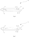
Fig. 2 is a schematic view of an interior of the foldable terminal illustrated inFig. 1 . -
Fig. 3 is a schematic view of part III of the foldable terminal illustrated inFig. 2 . -
Fig. 4 is a schematic view of the foldable terminal illustrated inFig. 1 in a second bending state. -
Fig. 5 is a schematic view of the foldable terminal illustrated inFig. 1 in a third bending state. -
Fig. 6 is a schematic view of a magnetic attraction assembly of the foldable terminal illustrated inFig. 4 in a coupling position. -
Fig. 7 is a schematic view of a magnetic attraction assembly of the foldable terminal illustrated inFig. 4 in another coupling position. -
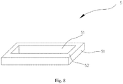
Fig. 8 is a schematic view of a ferromagnetic shielding assembly of the foldable terminal illustrated inFig. 1 . - Technical solutions in embodiments of the present disclosure will be clearly and completely described below with reference to the accompanying drawings in the embodiments of the present disclosure.
- A
foldable terminal 100 according to embodiments of the present disclosure may be any apparatus having communication and storage functions, such as a tablet computer, a mobile phone, an electronic reader, a remote controller, a personal computer (PC), a notebook computer, an on-board apparatus, an internet television, a wearable apparatus, or other smart apparatuses having internet functions. - Referring to
Figs. 1 to 5 , thefoldable terminal 100 according to the present disclosure includes abody 1, aflexible screen assembly 2, amagnetic attraction assembly 3 and amagnetic buffer assembly 4. Thebody 1 includes anupper part 11 and alower part 12 electrically coupled to theupper part 11, and theupper part 12 and thelower part 11 are provided with abending gap 14 therebetween. - The
body 1 includes theupper part 11, abending part 13 and thelower part 12 coupled sequentially. Thebody 1 includes an upper end and a lower end opposite to each other, the upper end is an end of theupper part 11 away from thebending part 13, and the lower end is an end of thelower part 12 away from thebending part 13. - The
flexible screen assembly 2 is disposed to a surface of thebody 1. - The
magnetic attraction assembly 3 includes a firstmagnetic attraction member 31 and a secondmagnetic attraction member 32. The firstmagnetic attraction member 31 is disposed to theupper part 11 and adjacent to the upper end (i.e. away from the bending part 13). The secondmagnetic attraction member 32 is disposed to thelower part 12 and adjacent to the lower end (i.e. away from the bending part 13). When an included angle between theupper part 11 and thelower part 12 is 0 degree, the firstmagnetic attraction member 31 is attracted to the secondmagnetic attraction member 32. - The
magnetic buffer assembly 4 includes a firstmagnetic buffer member 41 and a secondmagnetic buffer member 42. The firstmagnetic buffer member 41 is disposed to theupper part 11 and adjacent to thebending part 13. The secondmagnetic buffer member 42 is disposed to thelower part 12 and adjacent to thebending part 13. When the included angle between theupper part 11 and thelower part 12 is greater that or less than 180 degrees, the firstmagnetic buffer member 41 and the secondmagnetic buffer member 42 repel each other. - By providing the first
magnetic buffer member 41 and the secondmagnetic buffer member 42 on theupper part 11 and thelower part 12 correspondingly, a user can sense a repulsive force between the firstmagnetic buffer member 41 and the secondmagnetic buffer member 42 when theupper part 11 is bent relative to thelower part 12 to prevent thefoldable terminal 100 from closing vigorously and inadvertently, thereby improving reliability of thefoldable terminal 100; meanwhile, by providing the firstmagnetic attraction member 31 and the secondmagnetic attraction member 32 to ends of theupper part 11 and thelower part 12 correspondingly, the firstmagnetic attraction member 31 is coupled to the secondmagnetic attraction member 32 when the included angle between theupper part 11 and thelower part 12 is 0 degree to maintain a bending state of thefoldable terminal 100, thereby providing thefoldable terminal 100 having high reliability and capable of maintaining an attaching state. - In the present embodiment, the
body 1 includes theupper part 11, thebending part 13 and thelower part 12. The structures of theupper part 11 and thelower part 12 are substantially identical, and the difference is thatelectronic components 113 integrated inside theupper part 11 and thelower part 12 are different. Theupper part 11 is now taken as an example for illustration, and a specific structure of thelower part 12 will not be described herein. - The
upper part 11 includes arectangular housing 111, acircuit board 112 and theelectronic component 113, theelectronic component 113 is integrated to thecircuit board 112, and thecircuit board 112 is fixedly disposed in therectangular housing 111. Theupper part 11 has a firstupper end 11a and a firstlower end 11b arranged opposite to each other, and afirst surface 11c and asecond surface 11d arranged opposite to each other. The firstlower end 11b defines a first opening so as to be electrically coupled to thelower part 12. Thelower part 12 has a secondupper end 12a and a secondlower end 12b arranged opposite to each other, and athird surface 12c and afourth surface 12d arranged opposite to each other. The secondupper end 12a defines a second opening. - The
first surface 11c and thethird surface 12c are located at one side of thebody 1 and flush with each other to form anobverse surface 1a of thebody 1, and thesecond surface 11d and thefourth surface 12d are located at another side ofbody 1 and flush with each other to form aback surface 1b of thebody 1. Thelower part 12 is electrically coupled to theupper part 11, and thelower part 12 and theupper part 11 are provided with thebending gap 14 therebetween so as to be coupled to thebending part 13, such that thebody 1 can be bent into a bending state in which thefirst surface 11c is attached to thethird surface 12c, or another bending state in which thesecond surface 11d is attached to thefourth surface 12d. - Preferably, referring to
Figs. 2 and3 , an end of theflexible circuit board 114 extends into the first opening and is electrically coupled to thecircuit board 112 in theupper part 11, and the other end of theflexible circuit board 114 extends into the second opening and is electrically coupled to an interior of thelower part 12, so as to achieve electrical coupling between theupper part 11 and thelower part 12, such that theupper part 11 and thelower part 12 can form a whole, and bending performance of a bending area can also be improved. Certainly, in other embodiments, theflexible circuit board 114 may also be replaced by a flat cable. - Further, the
bending part 13 may be a sheet made of materials which can be bent repeatedly and has elasticity. By providing thebending part 13 of a sheet structure to surfaces of theupper part 11 and thelower part 12, an open-close angle between theupper part 11 and thelower part 12 can range from 0 to 360 degrees. In this way, thebending part 13 has a simple structure, thus facilitating assembling of thefoldable terminal 100. - Preferably, the
bending part 13 is a soft metal sheet, thereby further enhancing bending durability of thefoldable terminal 100. - Specifically, in order to further improve a flatness of the surface of the
body 1, an outer surface of thebending part 13 is flush with theback surface 1b of thebody 1. - The
bending part 13 resembles a strip, and includes an upper coupling section and a lower coupling section arranged opposite to each other. The upper coupling section is coupled to an interior of the firstlower end 11b of theupper part 11 through a screw, the lower coupling section is coupled to an interior of the secondupper end 12a of thelower part 12 through a screw, and the outer surface of thebending part 13 is flush with theback surface 1b of thebody 1 when thebending part 13 is coupled to the surfaces of theupper part 11 and thelower part 12, thereby improving the flatness of the surface of thebody 1. As the bendingpart 13 has elasticity and is stretchable, the open-close angle between theupper part 11 and thelower part 12 ranges from 0 to 360 degrees. - In general, the
foldable terminal 100 substantially has three bending states: in a first bending state A as illustrated inFig. 1 , the open-close angle between theupper part 11 and thelower part 12 is 180 degrees, and thefoldable terminal 100 forms a linear shape; in a second bending state B as illustrated inFig. 4 , the open-close angle between theupper part 11 and thelower part 12 is 0 degree, theobverse surface 1a of thebody 1 is an inner bending surface when thefoldable terminal 100 is bent; in a third bending state C as illustrated inFig. 5 , the open-close angle between theupper part 11 and thelower part 12 is 0 degree, theback surface 1b of thebody 1 is the inner bending surface when thefoldable terminal 100 is bent. Certainly, in other embodiments, the bendingpart 13 may also be a silicone sheet, and the bendingpart 13 is adhered to the surfaces of theupper part 11 and thelower part 12. The bendingpart 13 may also be an elastic watch strap structure, or the like. - In the present embodiment, the
flexible screen assembly 2 is disposed to theobverse surface 1a of thebody 1. Theflexible screen assembly 2 has a touch function, and thefoldable terminal 100 can be interacted with by operating on theflexible screen assembly 2. - In the present embodiment, preferably, the first
magnetic attraction member 31 is a magnet. The firstmagnetic attraction member 31 is fixedly disposed in therectangular housing 111 of theupper part 11, adjacent to the firstupper end 11a and adjacent to thefirst surface 11c, i.e. adjacent to theflexible screen assembly 2. The secondmagnetic attraction member 32 is a magnet. The secondmagnetic attraction member 32 is fixedly disposed in therectangular housing 111 of thelower part 12, adjacent to the secondlower end 12b, and adjacent to thethird surface 12c, i.e. adjacent to theflexible screen assembly 2. - When the
foldable terminal 100 is bent into the second bending state B, a strong magnetic force is present between the firstmagnetic attraction member 31 and the secondmagnetic attraction member 32, the firstmagnetic attraction member 31 and the secondmagnetic attraction member 32 are attracted together, such that theupper part 11 can be tightly attached to thelower part 12, that is, a folding of thefoldable terminal 100 can be achieved, to reduce a size of thefoldable terminal 100, thereby facilitating carrying of thefoldable terminal 100. - In general, both of the first
magnetic attraction member 31 and the secondmagnetic attraction member 32 are made of magnets, such that coupling performance of themagnetic attraction assembly 3 can be further improved. - It should be understood that, the first
magnetic attraction member 31 is the magnet and is disposed inside theupper part 11, and the secondmagnetic attraction member 32 is iron. - It should be understood that, the first
magnetic attraction member 31 is iron and is disposed inside theupper part 11, and the secondmagnetic attraction member 32 is the magnet and disposed inside thelower part 12. - Preferably, the first
magnetic attraction member 31 and the secondmagnetic attraction member 32 are adhered to theupper part 11 and thelower part 12 correspondingly. In this arrangement, fixing of themagnetic attraction assembly 3 can be further simplified, and coupling strength between themagnetic attraction assembly 3 and thefoldable terminal 100 can be improved. - In the present embodiment, the first
magnetic buffer member 41 is disposed inside therectangular housing 111 of theupper part 11 and adjacent to the firstlower end 11b; the secondmagnetic buffer member 42 is disposed inside thelower part 12 and adjacent to the secondupper end 12a. When thefoldable terminal 100 is changed from the first bending state A to the second bending state B or the third bending state C, the user will realize that he/she is closing thefoldable terminal 100 due to the repulsive force of themagnetic buffer assembly 4, so as to reduce the probability of damage to thefoldable terminal 100 which is caused by a collision between theupper part 11 and thelower part 12 when thefoldable terminal 100 is closed vigorously and inadvertently by the user, such that the reliability of thefoldable terminal 100 is further improved. - Preferably, the first
magnetic buffer member 41 and the secondmagnetic buffer member 42 are adhered to theupper part 11 and thelower part 12 correspondingly. In this arrangement, fixing of themagnetic buffer assembly 4 can be further simplified, and coupling strength between themagnetic buffer assembly 4 and thefoldable terminal 100 can be improved. - For a further improvement, both of the first
magnetic attraction member 31 and the secondmagnetic attraction member 32 are strip-shaped; or the firstmagnetic attraction member 31 is strip-shaped, and the secondmagnetic attraction member 32 is cylindrical. - In the present embodiment, referring to
Figs. 6 and 7 , both of the firstmagnetic attraction member 31 and the secondmagnetic attraction member 32 are strip-shaped, alignment difficulty of the firstmagnetic attraction member 31 and the secondmagnetic attraction member 32 is further reduced. Referring toFig. 6 , the firstmagnetic attraction member 31 includes a first attachingpart 31a and a second attachingpart 31b arranged opposite to each other in an extending direction from the firstupper end 11a to the firstlower end 11b, the secondmagnetic attraction member 32 includes a third attachingpart 32a and a fourth attachingpart 32b arranged opposite to each other in an extending direction from the secondupper end 12a to the secondlower end 12b, and the second attachingpart 31b may be magnetically attached to the third attachingpart 32a by changing the bending shape of thebody 1; or, referring toFig. 7 , the first attachingpart 31a may be magnetically attached to the fourth attachingpart 32b, etc. Certainly, in other embodiments, the firstmagnetic attraction member 31 may also be strip-shaped, and the secondmagnetic attraction member 32 is cylindrical. - For a further improvement, both of the first
magnetic buffer member 41 and the secondmagnetic buffer member 42 are strip-shaped; or the firstmagnetic buffer member 41 is strip-shaped, and the secondmagnetic buffer member 42 is cylindrical. - In the present embodiment, both of the first
magnetic buffer member 41 and the secondmagnetic buffer member 42 are strip-shaped, the alignment difficulty of the firstmagnetic buffer member 41 and the secondmagnetic buffer member 42 can be further reduced. Certainly, in other embodiments, the firstmagnetic buffer member 41 may also be strip-shaped, and the secondmagnetic buffer member 42 is cylindrical. - For a further improvement, referring to
Fig. 8 , thefoldable terminal 100 also includes fourferromagnetic shielding members 5, and the fourferromagnetic shielding members 5 surround circumferential surfaces of the firstmagnetic attraction member 31, the secondmagnetic attraction member 32, the firstmagnetic buffer member 41 and the secondmagnetic buffer member 42 correspondingly. - By providing the
ferromagnetic shielding members 5 to the circumferential surfaces of the firstmagnetic attraction member 31, the secondmagnetic attraction member 32, the firstmagnetic buffer member 41 and the secondmagnetic buffer member 42 correspondingly, influence of themagnetic attraction assembly 3 and themagnetic buffer assembly 4 on otherelectronic components 113 in the housing of thefoldable terminal 100 can be further reduced. - In the present embodiment, preferably, in order to further reduce the influence of the
magnetic attraction assembly 3 on otherelectronic components 113 in the housing of thefoldable terminal 100, theferromagnetic shielding member 5 includes twoiron frame casings 51 andfoam 52. Oneiron frame casing 51 is fitted in the otheriron frame casing 51, the twoiron frame casings 51 define a filling gap therebetween, and thefoam 52 is clamped in the filling gap. Specifically, the twoiron frame casings 51 have the same shape, the difference is that one of the twoiron frame casings 51 is smaller, and the other is larger. Accordingly, the smalleriron frame casing 51 is disposed in the largeriron frame casing 51, and the filling gap for filling thefoam 52 is formed between circumferential surfaces of the twoiron frame casings 51. Preferably, in order to further enhance ferromagnetic shielding performance of theferromagnetic shielding member 5, a wall thickness of theiron frame casing 51 is 0.5mm, and the filling gap is 10 mm. The fourferromagnetic shielding members 5 are disposed to the circumferential surfaces of the firstmagnetic attraction member 31, the secondmagnetic attraction member 32, the firstmagnetic buffer member 41 and the secondmagnetic buffer member 42 correspondingly, such that magnetism of the magnetic attraction members and the magnetic buffer members will not influence theelectronic components 113 in thefoldable terminal 100, such as a compass or a gravity sensor. Certainly, in other embodiments, theferromagnetic shielding member 5 is an anti-magnetic hood. The fourferromagnetic shielding members 5 cover the first magnetic attraction member, the second magnetic attraction member, the first magnetic buffer member and the second magnetic buffer member correspondingly, so as to further reduce the influence of themagnetic attraction assembly 3 and themagnetic buffer assembly 4 on otherelectronic components 113 in the housing of thefoldable terminal 100. - When the
foldable terminal 100 is in use, theupper part 11 can be bent to 180 degrees (at least greater than 0 degree) relative to thelower part 12 by overcoming a magnetic attraction force between the firstmagnetic attraction member 31 and the secondmagnetic attraction member 32, and thefoldable terminal 100 can be interacted with by clicking and touching theflexible screen assembly 2; when thefoldable terminal 100 is not in use and theflexible screen assembly 2 of thefoldable terminal 100 is not desired to be exposed, thefoldable terminal 100 can be bought into the second bending state B, during the bending of thefoldable terminal 100, themagnetic buffer assembly 4 repels each other to perform a fool-proof reminder for the user, and the repulsive force in themagnetic buffer assembly 4 is continued to be overcome to make the firstmagnetic attraction member 31 magnetically attracted to the secondmagnetic attraction member 32, such that thefoldable terminal 100 is kept in the second bending state B; and when thefoldable terminal 100 is not in use but theflexible screen assembly 2 of thefoldable terminal 100 is desired to be exposed, thebody 1 is bent to bring thefoldable terminal 100 into the third bending state C. - In the
foldable terminal 100 according to the present disclosure, by providing the firstmagnetic buffer member 41 and the secondmagnetic buffer member 42 on theupper part 11 and thelower part 12 correspondingly, the user can sense the repulsive force between the firstmagnetic buffer member 41 and the secondmagnetic buffer member 42 when theupper part 11 is bent relative to thelower part 12 to prevent the foldable terminal 100 from closing vigorously and inadvertently, thereby improving the reliability of thefoldable terminal 100; meanwhile, by providing the firstmagnetic attraction member 31 and the secondmagnetic attraction member 32 to ends of theupper part 11 and thelower part 12 corrrespondingly, the firstmagnetic attraction member 31 is coupled to the secondmagnetic attraction member 32 when the included angle between theupper part 11 and thelower part 12 is 0 degree to maintain the bending state of thefoldable terminal 100, thereby providing thefoldable terminal 100 having high reliability and capable of maintaining the attaching state. - In the
foldable terminal 100 according to the present disclosure, by further making the outer surface of the bendingpart 13 flush with theback surface 1b of thebody 1, the flatness of the surface of thebody 1 is further improved. - In the
foldable terminal 100 according to the present disclosure, by further providing theferromagnetic shielding members 5 to the circumferential surfaces of themagnetic attraction assembly 3 and themagnetic buffer assembly 4 correspondingly, the influence of themagnetic attraction assembly 3 and themagnetic buffer assembly 4 on otherelectronic components 113 in the housing of thefoldable terminal 100 can be further reduced. - The above reveals preferred embodiments of the present disclosure, it should be noted that, it is also possible for those skilled in the art to further make some improvements and modifications without departing from the principle of the present disclosure, and these improvements and modifications are deemed to fall into the scope of the present disclosure.
Claims (20)
- A foldable terminal, comprising a body, a magnetic attraction assembly and a magnetic buffer assembly;
the body comprising an upper part, a bending part and a lower part sequentially coupled;
the magnetic attraction assembly comprising a first magnetic attraction member and a second magnetic attraction member, the first magnetic attraction member being disposed to the upper part and away from the bending part; the second magnetic attraction member being disposed to the lower part and away from the bending part; and when an included angle between the upper part and the lower part is 0 degree, the first magnetic attraction member being attracted to the second magnetic attraction member;
the magnetic buffer assembly comprising a first magnetic buffer member and a second magnetic buffer member, the first magnetic buffer member being disposed to the upper part and adjacent to the bending part; the second magnetic buffer member being disposed to the lower part and adjacent to the bending part; and when the included angle between the upper part and the lower part is greater than or less than 180 degrees, the first magnetic buffer member and the second magnetic buffer member repelling each other. - The foldable terminal according to claim 1, further comprising a flexible screen assembly disposed to a surface of the body.
- The foldable terminal according to claim 1, wherein the magnetic attraction assembly and/or the magnetic buffer assembly are/is adhered to the body.
- The foldable terminal according to claim 1, wherein the first magnetic attraction member comprises a first attaching part and a second attacning part spaced apart from each other, and the second magnetic attraction member is attached to the first attaching part and/or the second attaching part.
- The foldable terminal according to claim 4, wherein the first magnetic attraction member is strip-shaped.
- The foldable terminal according to claim 1 or 4, wherein the second magnetic attraction member comprises a third attaching part and a fourth attaching part spaced apart from each other, and the first magnetic attraction member is attached to the third attaching part and/or the fourth attaching part.
- The foldable terminal according to claim 6, wherein the second magnetic attraction member is strip-shaped.
- The foldable terminal according to claim 1, further comprising four ferromagnetic shielding members surrounding circumferential surfaces of the first magnetic attraction member, the second magnetic attraction member, the first magnetic buffer member and the second magnetic buffer member correspondingly.
- The foldable terminal according to claim 8, wherein the ferromagnetic shielding member comprises foam and two iron frame casings, one iron frame casing is fitted in the other iron frame casing, and the foam is clamped between the two iron frame casings.
- The foldable terminal according to claim 8, wherein the ferromagnetic shielding member is an anti-magnetic hood.
- The foldable terminal according to claim 1, wherein the upper part and the lower part are provided with a flat cable therebetween; or the upper part and the lower part are provided with a flexible circuit board therebetween.
- The foldable terminal according to claim 1, wherein the bending part is a sheet, coupled between the upper part and the lower part, and arranged opposite to a flexible screen assembly.
- The foldable terminal according to claim 12, wherein an outer surface of the bending part is flush with surfaces of the upper part and the lower part.
- A foldable terminal, comprising a body, a magnetic attraction assembly and a magnetic buffer assembly;
the body comprising a bending part, and an upper part and a lower part coupled to two opposite sides of the bending part;
the magnetic attraction assembly comprising two magnetic attraction members attracting each other, the two magnetic attraction members being disposed to an end of the upper part away from the bending part and an end of the lower part away from the bending part correspondingly, and configured to maintain an attaching state between the upper part and the lower part;
the magnetic buffer assembly comprising two magnetic buffer members repelling each other, the two magnetic buffer members being disposed to an end of the upper part adjacent to the bending part and an end of the lower part adjacent to the bending part correpondingly, and configured to provide a repulsive force when the upper part and the lower part approach each other. - The foldable terminal according to claim 14, wherein the two magnetic attraction members are fully or partially attached to each other.
- The foldable terminal according to claim 14 or 15, wherein at least one of the magnetic attraction members comprises two attaching parts spaced apart from each other, and the other magnetic attraction member is attached to at least one of the attaching parts.
- The foldable terminal according to claim 16, wherein at least one of the magnetic attraction members is strip-shaped.
- The foldable terminal according to claim 14 or 15, wherein at least one of the magnetic attraction member is a magnet.
- The foldable terminal according to claim 14 or 15, further comprising a plurality of ferromagnetic shielding members surrounding circumferential surfaces of the two magnetic attraction members and the two magnetic buffer members correspondingly to achieve electromagnetic shielding.
- The foldable terminal according to claim 19, wherein each ferromagnetic shielding member comprises two iron frame casings nested with each other and foam clamped between the two iron frame casings.
Applications Claiming Priority (2)
| Application Number | Priority Date | Filing Date | Title |
|---|---|---|---|
| CN201511026167.6A CN105491194B (en) | 2015-12-29 | 2015-12-29 | Folding terminal |
| PCT/CN2016/112999 WO2017114460A1 (en) | 2015-12-29 | 2016-12-29 | Folding terminal |
Publications (3)
| Publication Number | Publication Date |
|---|---|
| EP3379809A1 true EP3379809A1 (en) | 2018-09-26 |
| EP3379809A4 EP3379809A4 (en) | 2018-09-26 |
| EP3379809B1 EP3379809B1 (en) | 2020-10-21 |
Family
ID=55677900
Family Applications (1)
| Application Number | Title | Priority Date | Filing Date |
|---|---|---|---|
| EP16881249.3A Active EP3379809B1 (en) | 2015-12-29 | 2016-12-29 | Folding terminal |
Country Status (6)
| Country | Link |
|---|---|
| US (2) | US10539981B2 (en) |
| EP (1) | EP3379809B1 (en) |
| JP (1) | JP6701344B2 (en) |
| KR (1) | KR102089489B1 (en) |
| CN (2) | CN108683758A (en) |
| WO (1) | WO2017114460A1 (en) |
Cited By (1)
| Publication number | Priority date | Publication date | Assignee | Title |
|---|---|---|---|---|
| WO2021231593A1 (en) * | 2020-05-14 | 2021-11-18 | Microsoft Technology Licensing, Llc | Magnetic closure system for a device |
Families Citing this family (38)
| Publication number | Priority date | Publication date | Assignee | Title |
|---|---|---|---|---|
| CN108683758A (en) * | 2015-12-29 | 2018-10-19 | 广东欧珀移动通信有限公司 | a folding terminal |
| CN106131251B (en) | 2016-07-08 | 2018-07-06 | 广东欧珀移动通信有限公司 | Flexible screen supporting structure, flexible display screen module and mobile terminal |
| US10705569B2 (en) | 2016-07-08 | 2020-07-07 | Guangdong Oppo Mobile Telecommunications Corp., Ltd. | Support structure for supporting flexible display screen, and flexible display screen module |
| KR102398331B1 (en) * | 2017-11-01 | 2022-05-16 | 엘지전자 주식회사 | Flexible display unit and mobile terminal having the same |
| CN108271324B (en) * | 2017-12-20 | 2024-04-26 | 广东长盈精密技术有限公司 | Shell and mobile terminal |
| CN108076175A (en) * | 2017-12-21 | 2018-05-25 | 广东长盈精密技术有限公司 | A kind of mobile terminal |
| CN110730255A (en) * | 2018-07-16 | 2020-01-24 | 北京小米移动软件有限公司 | Foldable terminal |
| CN109803503B (en) | 2018-12-29 | 2021-03-16 | 维沃移动通信有限公司 | Terminal device |
| KR102577249B1 (en) * | 2019-01-21 | 2023-09-12 | 삼성전자주식회사 | Electronic device including magnet and magnetic shielding member |
| US10469635B1 (en) * | 2019-01-23 | 2019-11-05 | Motorola Mobility Llc | Hinged electronic device with chambers accommodating a dynamic flexible substrate and corresponding systems |
| KR102730100B1 (en) | 2019-02-20 | 2024-11-14 | 삼성전자주식회사 | Pordable device |
| CN109859634B (en) * | 2019-03-25 | 2020-09-01 | 武汉华星光电半导体显示技术有限公司 | Foldable display device |
| CN109917858A (en) * | 2019-03-27 | 2019-06-21 | Oppo广东移动通信有限公司 | Folding state obtaining method and device of folding screen in electronic equipment and electronic equipment |
| KR102749454B1 (en) | 2019-05-03 | 2025-01-03 | 삼성전자주식회사 | Foldable electronic device including hidden damper |
| US11206741B2 (en) * | 2019-07-16 | 2021-12-21 | Au Optronics Corporation | Display |
| KR102822180B1 (en) * | 2019-08-02 | 2025-06-18 | 삼성전자주식회사 | A foldable electronic device comprising a magnet |
| CN110718152B (en) * | 2019-10-21 | 2022-04-12 | Oppo广东移动通信有限公司 | Folding screen assembly and mobile terminal |
| CN112751951B (en) | 2019-10-29 | 2022-03-15 | Oppo广东移动通信有限公司 | Folding device and electronic equipment |
| KR102790087B1 (en) * | 2020-01-02 | 2025-04-03 | 삼성전자주식회사 | An electronic device comprising a magnetic structure |
| CN111341217B (en) * | 2020-02-21 | 2021-10-08 | 武汉华星光电半导体显示技术有限公司 | Display panel and display device |
| CN111402736B (en) * | 2020-03-26 | 2022-03-08 | 武汉华星光电半导体显示技术有限公司 | Display device |
| US11202382B2 (en) * | 2020-04-09 | 2021-12-14 | Wuhan China Star Optoelectronics Semiconductor Display Technology Co., Ltd. | Display device |
| CN111654564B (en) * | 2020-05-25 | 2021-02-09 | 维沃移动通信有限公司 | Screen assembly and electronic equipment |
| WO2022014928A1 (en) | 2020-07-16 | 2022-01-20 | 삼성전자 주식회사 | Electronic device comprising magnet array |
| CN112051892A (en) * | 2020-08-12 | 2020-12-08 | 武汉华星光电半导体显示技术有限公司 | Mobile terminal |
| CN114430431A (en) * | 2020-10-29 | 2022-05-03 | 北京小米移动软件有限公司 | Foldable electronic equipment |
| KR102919929B1 (en) * | 2020-12-04 | 2026-01-29 | 삼성전자주식회사 | Electronic device including flexible display |
| KR20220086347A (en) * | 2020-12-16 | 2022-06-23 | 삼성전자주식회사 | Foldable electronic device and method of operation therof |
| TWI753744B (en) * | 2021-01-12 | 2022-01-21 | 和碩聯合科技股份有限公司 | Buffer assembly and electronic equipment with buffer assembly |
| KR20230012824A (en) * | 2021-07-16 | 2023-01-26 | 삼성전자주식회사 | Electronic device |
| CN113539107B (en) * | 2021-07-23 | 2023-09-19 | 上海天马微电子有限公司 | a display device |
| KR102861916B1 (en) | 2021-08-10 | 2025-09-19 | 삼성전자 주식회사 | Electronic device including shielding member |
| KR102871048B1 (en) * | 2021-08-10 | 2025-10-15 | 삼성전자주식회사 | Flexible display module including shielding structure and waterproof structure and electronic device including the same |
| CN114126283B (en) * | 2021-11-09 | 2024-05-31 | 维沃移动通信有限公司 | An electronic device |
| CN115643331B (en) * | 2022-11-08 | 2025-09-26 | Oppo广东移动通信有限公司 | Folding mechanism and electronic equipment |
| KR20240139149A (en) * | 2023-03-10 | 2024-09-23 | 삼성디스플레이 주식회사 | Electronic apparatus |
| CN117238213A (en) * | 2023-08-30 | 2023-12-15 | 厦门天马显示科技有限公司 | Display device |
| TWI872997B (en) * | 2024-03-22 | 2025-02-11 | 富世達股份有限公司 | Foldable electronic devices |
Family Cites Families (43)
| Publication number | Priority date | Publication date | Assignee | Title |
|---|---|---|---|---|
| JP3157053B2 (en) | 1992-09-16 | 2001-04-16 | ティーディーケイ株式会社 | Method for identifying the binding mode of a DNA agent |
| CN1302006A (en) * | 1999-12-29 | 2001-07-04 | 仁宝电脑工业股份有限公司 | Magnetic open and close device for portable computer |
| US6653919B2 (en) * | 2001-02-02 | 2003-11-25 | Wistron Corp | Magnetic closure apparatus for portable computers |
| KR100354567B1 (en) * | 2001-04-24 | 2002-10-04 | 주식회사 에이터치 | Protector structure for terminal of data transmission and receipt |
| JP2004110304A (en) * | 2002-09-17 | 2004-04-08 | Brother Ind Ltd | Input device with foldable display and keyboard, and personal computer with the input device |
| TWI241513B (en) * | 2003-03-26 | 2005-10-11 | Benq Corp | Detachable keyboard structure |
| US6929291B2 (en) * | 2003-07-28 | 2005-08-16 | Inventec Corp. | Magnetic lock |
| CN2662550Y (en) * | 2003-10-16 | 2004-12-08 | 明基电通股份有限公司 | foldable mobile phone |
| KR100672448B1 (en) * | 2004-07-16 | 2007-01-24 | 엘지전자 주식회사 | Clamshell mobile communication terminal |
| JP4503395B2 (en) * | 2004-08-16 | 2010-07-14 | パナソニック株式会社 | Mobile device |
| CN2760726Y (en) * | 2004-12-06 | 2006-02-22 | 金宝电子工业股份有限公司 | Magnetic switch for foldable electronic device and foldable electronic device |
| US20070097014A1 (en) * | 2005-10-31 | 2007-05-03 | Solomon Mark C | Electronic device with flexible display screen |
| TWI285305B (en) * | 2005-11-07 | 2007-08-11 | High Tech Comp Corp | Auto-aligning and connecting structure between electronic device and accessory |
| TWI291105B (en) * | 2005-11-30 | 2007-12-11 | High Tech Comp Corp | Multi-configuration portable electronic device |
| US7583500B2 (en) * | 2005-12-13 | 2009-09-01 | Apple Inc. | Electronic device having magnetic latching mechanism |
| US7593524B2 (en) * | 2006-11-27 | 2009-09-22 | Nokia Corporation | Hinge arrangement |
| US20080278269A1 (en) * | 2007-05-10 | 2008-11-13 | Ernesto Ramirez | System and Method for an Information Handling System Articulated Magnetic Latch |
| TWI340618B (en) * | 2007-10-23 | 2011-04-11 | Htc Corp | Electronic device |
| CN101677335A (en) * | 2008-09-19 | 2010-03-24 | 深圳富泰宏精密工业有限公司 | electronic apparatus |
| EP2219347B1 (en) * | 2009-02-13 | 2015-10-28 | BlackBerry Limited | System for opening and closing a mobile communication device |
| US20100238620A1 (en) * | 2009-03-23 | 2010-09-23 | Ram David Adva Fish | Magnetic Notebooks and Tablets |
| KR101753582B1 (en) * | 2009-11-03 | 2017-07-06 | 엘지전자 주식회사 | A portable terminal device |
| US8593800B2 (en) * | 2009-11-05 | 2013-11-26 | Panasonic Corporation | Electronic equipment with hinge mechanism |
| JP3157053U (en) * | 2009-11-11 | 2010-01-28 | オリエントコンピュータ株式会社 | Passbook case with magnetic defense and skimming prevention function |
| CN201947600U (en) * | 2011-01-13 | 2011-08-24 | 三环瓦克华(北京)磁性器件有限公司 | Magnetic field shielding device of magnetizing magnetic material |
| US8787016B2 (en) * | 2011-07-06 | 2014-07-22 | Apple Inc. | Flexible display devices |
| WO2013101030A1 (en) * | 2011-12-29 | 2013-07-04 | Intel Corporation | Mobile device to operate in tablet mode and phone mode |
| JP6045795B2 (en) * | 2012-02-23 | 2016-12-14 | 株式会社リブドゥコーポレーション | Water absorbing body and absorbent article using the same |
| US8705229B2 (en) * | 2012-04-25 | 2014-04-22 | Hewlett-Packard Development Company, L.P. | Foldable electronic devices including a first and a second magnet |
| US8947874B2 (en) * | 2012-06-08 | 2015-02-03 | Bartley K. Andre | Portable computing device with a housing secured by a magnetic element and related method |
| KR101991940B1 (en) * | 2012-08-08 | 2019-06-24 | 삼성전자주식회사 | Portable electronic apparatus |
| JP2014103631A (en) * | 2012-11-22 | 2014-06-05 | Nippon Antenna Co Ltd | Portable information device |
| CN103049054B (en) | 2013-01-25 | 2016-12-28 | 联宝(合肥)电子科技有限公司 | A kind of effective solution foldable computer closes the method that screen post gap is uneven |
| US9348362B2 (en) | 2013-02-08 | 2016-05-24 | Samsung Electronics Co., Ltd. | Flexible portable terminal |
| TW201445288A (en) * | 2013-05-31 | 2014-12-01 | Hon Hai Prec Ind Co Ltd | Electronic device |
| TWI495987B (en) | 2013-06-25 | 2015-08-11 | Wistron Corp | Hinge and foldable electronic apparatus |
| CN203632709U (en) | 2013-10-09 | 2014-06-04 | 冯振华 | Soft screen foldable mobile phone |
| KR101727971B1 (en) | 2014-02-21 | 2017-04-18 | 삼성전자주식회사 | Foldable device |
| US9798359B2 (en) * | 2014-02-21 | 2017-10-24 | Samsung Electronics Co., Ltd. | Foldable device |
| CN204069046U (en) * | 2014-06-03 | 2014-12-31 | 冯振华 | Two soft screen clamshell phone |
| CN105611006B (en) * | 2015-12-29 | 2018-03-27 | 广东欧珀移动通信有限公司 | A kind of collapsible terminal with flexible screen |
| CN108683758A (en) | 2015-12-29 | 2018-10-19 | 广东欧珀移动通信有限公司 | a folding terminal |
| US10146267B2 (en) * | 2016-12-31 | 2018-12-04 | Lenovo (Singapore) Pte. Ltd. | Computing device with elastomeric hinge assembly |
-
2015
- 2015-12-29 CN CN201810414036.2A patent/CN108683758A/en active Pending
- 2015-12-29 CN CN201511026167.6A patent/CN105491194B/en active Active
-
2016
- 2016-12-29 EP EP16881249.3A patent/EP3379809B1/en active Active
- 2016-12-29 KR KR1020187017465A patent/KR102089489B1/en not_active Expired - Fee Related
- 2016-12-29 WO PCT/CN2016/112999 patent/WO2017114460A1/en not_active Ceased
- 2016-12-29 JP JP2018531405A patent/JP6701344B2/en not_active Expired - Fee Related
- 2016-12-29 US US16/060,731 patent/US10539981B2/en active Active
-
2018
- 2018-11-15 US US16/192,368 patent/US10459490B2/en active Active
Cited By (3)
| Publication number | Priority date | Publication date | Assignee | Title |
|---|---|---|---|---|
| WO2021231593A1 (en) * | 2020-05-14 | 2021-11-18 | Microsoft Technology Licensing, Llc | Magnetic closure system for a device |
| NL2025586B1 (en) * | 2020-05-14 | 2021-11-30 | Microsoft Technology Licensing Llc | Magnetic closure system for a device |
| US12352076B2 (en) | 2020-05-14 | 2025-07-08 | Microsoft Technology Licensing, Llc | Magnetic closure system for a device |
Also Published As
| Publication number | Publication date |
|---|---|
| US20190086966A1 (en) | 2019-03-21 |
| KR20180083929A (en) | 2018-07-23 |
| US10459490B2 (en) | 2019-10-29 |
| CN108683758A (en) | 2018-10-19 |
| CN105491194A (en) | 2016-04-13 |
| US10539981B2 (en) | 2020-01-21 |
| JP2019507406A (en) | 2019-03-14 |
| JP6701344B2 (en) | 2020-05-27 |
| KR102089489B1 (en) | 2020-03-17 |
| CN105491194B (en) | 2018-05-29 |
| WO2017114460A1 (en) | 2017-07-06 |
| US20180364761A1 (en) | 2018-12-20 |
| EP3379809A4 (en) | 2018-09-26 |
| EP3379809B1 (en) | 2020-10-21 |
Similar Documents
| Publication | Publication Date | Title |
|---|---|---|
| US10459490B2 (en) | Foldable terminal | |
| CN108491107B (en) | a mobile terminal | |
| EP3338322B1 (en) | Electronic device | |
| CN103238109B (en) | Camera module | |
| CN109661131B (en) | Electronic equipment | |
| US10652376B2 (en) | Mobile terminal | |
| US8259091B2 (en) | Handheld electronic device | |
| EP2469808A2 (en) | Mobile device | |
| US20170153665A1 (en) | Portable electronic device | |
| US8634196B2 (en) | Locking mechanism and electronic device | |
| CN104425168B (en) | Slide switch and opening-closing structure thereof, and there is the electronic installation of this slide switch | |
| CN108028591A (en) | Linear vibration motor | |
| US8840200B2 (en) | Electronic device and movable fixing structure thereof | |
| CN207782862U (en) | Functional components and mobile terminals | |
| US20140347813A1 (en) | Electronic device opened by magnetic force | |
| JP6570958B2 (en) | Portable information processing device | |
| KR20170111969A (en) | Mobile terminal | |
| CN114222012B (en) | Terminal Equipment | |
| US8391001B2 (en) | Electronic device and sliding hinge thereof | |
| US20150102193A1 (en) | Magnet fixing structure and electronic device having the same | |
| US20120218474A1 (en) | Broadcast Receiver and Electronic Device | |
| KR20170111971A (en) | Mobile terminal | |
| KR20140145846A (en) | Camera module | |
| US20180019778A1 (en) | Mobile phone case |
Legal Events
| Date | Code | Title | Description |
|---|---|---|---|
| STAA | Information on the status of an ep patent application or granted ep patent |
Free format text: STATUS: THE INTERNATIONAL PUBLICATION HAS BEEN MADE |
|
| PUAI | Public reference made under article 153(3) epc to a published international application that has entered the european phase |
Free format text: ORIGINAL CODE: 0009012 |
|
| STAA | Information on the status of an ep patent application or granted ep patent |
Free format text: STATUS: REQUEST FOR EXAMINATION WAS MADE |
|
| 17P | Request for examination filed |
Effective date: 20180607 |
|
| A4 | Supplementary search report drawn up and despatched |
Effective date: 20180814 |
|
| AK | Designated contracting states |
Kind code of ref document: A1 Designated state(s): AL AT BE BG CH CY CZ DE DK EE ES FI FR GB GR HR HU IE IS IT LI LT LU LV MC MK MT NL NO PL PT RO RS SE SI SK SM TR |
|
| AX | Request for extension of the european patent |
Extension state: BA ME |
|
| DAV | Request for validation of the european patent (deleted) | ||
| DAX | Request for extension of the european patent (deleted) | ||
| RAP1 | Party data changed (applicant data changed or rights of an application transferred) |
Owner name: GUANGDONG OPPO MOBILE TELECOMMUNICATIONS CORP., LT |
|
| GRAP | Despatch of communication of intention to grant a patent |
Free format text: ORIGINAL CODE: EPIDOSNIGR1 |
|
| STAA | Information on the status of an ep patent application or granted ep patent |
Free format text: STATUS: GRANT OF PATENT IS INTENDED |
|
| INTG | Intention to grant announced |
Effective date: 20200420 |
|
| GRAJ | Information related to disapproval of communication of intention to grant by the applicant or resumption of examination proceedings by the epo deleted |
Free format text: ORIGINAL CODE: EPIDOSDIGR1 |
|
| STAA | Information on the status of an ep patent application or granted ep patent |
Free format text: STATUS: REQUEST FOR EXAMINATION WAS MADE |
|
| GRAP | Despatch of communication of intention to grant a patent |
Free format text: ORIGINAL CODE: EPIDOSNIGR1 |
|
| STAA | Information on the status of an ep patent application or granted ep patent |
Free format text: STATUS: GRANT OF PATENT IS INTENDED |
|
| INTC | Intention to grant announced (deleted) | ||
| INTG | Intention to grant announced |
Effective date: 20200810 |
|
| GRAS | Grant fee paid |
Free format text: ORIGINAL CODE: EPIDOSNIGR3 |
|
| GRAA | (expected) grant |
Free format text: ORIGINAL CODE: 0009210 |
|
| STAA | Information on the status of an ep patent application or granted ep patent |
Free format text: STATUS: THE PATENT HAS BEEN GRANTED |
|
| AK | Designated contracting states |
Kind code of ref document: B1 Designated state(s): AL AT BE BG CH CY CZ DE DK EE ES FI FR GB GR HR HU IE IS IT LI LT LU LV MC MK MT NL NO PL PT RO RS SE SI SK SM TR |
|
| REG | Reference to a national code |
Ref country code: GB Ref legal event code: FG4D |
|
| REG | Reference to a national code |
Ref country code: CH Ref legal event code: EP |
|
| REG | Reference to a national code |
Ref country code: IE Ref legal event code: FG4D |
|
| REG | Reference to a national code |
Ref country code: AT Ref legal event code: REF Ref document number: 1327012 Country of ref document: AT Kind code of ref document: T Effective date: 20201115 |
|
| REG | Reference to a national code |
Ref country code: DE Ref legal event code: R096 Ref document number: 602016046494 Country of ref document: DE |
|
| REG | Reference to a national code |
Ref country code: AT Ref legal event code: MK05 Ref document number: 1327012 Country of ref document: AT Kind code of ref document: T Effective date: 20201021 |
|
| REG | Reference to a national code |
Ref country code: NL Ref legal event code: MP Effective date: 20201021 |
|
| PG25 | Lapsed in a contracting state [announced via postgrant information from national office to epo] |
Ref country code: NO Free format text: LAPSE BECAUSE OF FAILURE TO SUBMIT A TRANSLATION OF THE DESCRIPTION OR TO PAY THE FEE WITHIN THE PRESCRIBED TIME-LIMIT Effective date: 20210121 Ref country code: RS Free format text: LAPSE BECAUSE OF FAILURE TO SUBMIT A TRANSLATION OF THE DESCRIPTION OR TO PAY THE FEE WITHIN THE PRESCRIBED TIME-LIMIT Effective date: 20201021 Ref country code: PT Free format text: LAPSE BECAUSE OF FAILURE TO SUBMIT A TRANSLATION OF THE DESCRIPTION OR TO PAY THE FEE WITHIN THE PRESCRIBED TIME-LIMIT Effective date: 20210222 Ref country code: GR Free format text: LAPSE BECAUSE OF FAILURE TO SUBMIT A TRANSLATION OF THE DESCRIPTION OR TO PAY THE FEE WITHIN THE PRESCRIBED TIME-LIMIT Effective date: 20210122 Ref country code: FI Free format text: LAPSE BECAUSE OF FAILURE TO SUBMIT A TRANSLATION OF THE DESCRIPTION OR TO PAY THE FEE WITHIN THE PRESCRIBED TIME-LIMIT Effective date: 20201021 |
|
| REG | Reference to a national code |
Ref country code: LT Ref legal event code: MG4D |
|
| PG25 | Lapsed in a contracting state [announced via postgrant information from national office to epo] |
Ref country code: SE Free format text: LAPSE BECAUSE OF FAILURE TO SUBMIT A TRANSLATION OF THE DESCRIPTION OR TO PAY THE FEE WITHIN THE PRESCRIBED TIME-LIMIT Effective date: 20201021 Ref country code: BG Free format text: LAPSE BECAUSE OF FAILURE TO SUBMIT A TRANSLATION OF THE DESCRIPTION OR TO PAY THE FEE WITHIN THE PRESCRIBED TIME-LIMIT Effective date: 20210121 Ref country code: PL Free format text: LAPSE BECAUSE OF FAILURE TO SUBMIT A TRANSLATION OF THE DESCRIPTION OR TO PAY THE FEE WITHIN THE PRESCRIBED TIME-LIMIT Effective date: 20201021 Ref country code: LV Free format text: LAPSE BECAUSE OF FAILURE TO SUBMIT A TRANSLATION OF THE DESCRIPTION OR TO PAY THE FEE WITHIN THE PRESCRIBED TIME-LIMIT Effective date: 20201021 Ref country code: IS Free format text: LAPSE BECAUSE OF FAILURE TO SUBMIT A TRANSLATION OF THE DESCRIPTION OR TO PAY THE FEE WITHIN THE PRESCRIBED TIME-LIMIT Effective date: 20210221 Ref country code: ES Free format text: LAPSE BECAUSE OF FAILURE TO SUBMIT A TRANSLATION OF THE DESCRIPTION OR TO PAY THE FEE WITHIN THE PRESCRIBED TIME-LIMIT Effective date: 20201021 Ref country code: AT Free format text: LAPSE BECAUSE OF FAILURE TO SUBMIT A TRANSLATION OF THE DESCRIPTION OR TO PAY THE FEE WITHIN THE PRESCRIBED TIME-LIMIT Effective date: 20201021 |
|
| PG25 | Lapsed in a contracting state [announced via postgrant information from national office to epo] |
Ref country code: NL Free format text: LAPSE BECAUSE OF FAILURE TO SUBMIT A TRANSLATION OF THE DESCRIPTION OR TO PAY THE FEE WITHIN THE PRESCRIBED TIME-LIMIT Effective date: 20201021 Ref country code: HR Free format text: LAPSE BECAUSE OF FAILURE TO SUBMIT A TRANSLATION OF THE DESCRIPTION OR TO PAY THE FEE WITHIN THE PRESCRIBED TIME-LIMIT Effective date: 20201021 |
|
| REG | Reference to a national code |
Ref country code: DE Ref legal event code: R097 Ref document number: 602016046494 Country of ref document: DE |
|
| PG25 | Lapsed in a contracting state [announced via postgrant information from national office to epo] |
Ref country code: RO Free format text: LAPSE BECAUSE OF FAILURE TO SUBMIT A TRANSLATION OF THE DESCRIPTION OR TO PAY THE FEE WITHIN THE PRESCRIBED TIME-LIMIT Effective date: 20201021 Ref country code: SK Free format text: LAPSE BECAUSE OF FAILURE TO SUBMIT A TRANSLATION OF THE DESCRIPTION OR TO PAY THE FEE WITHIN THE PRESCRIBED TIME-LIMIT Effective date: 20201021 Ref country code: EE Free format text: LAPSE BECAUSE OF FAILURE TO SUBMIT A TRANSLATION OF THE DESCRIPTION OR TO PAY THE FEE WITHIN THE PRESCRIBED TIME-LIMIT Effective date: 20201021 Ref country code: CZ Free format text: LAPSE BECAUSE OF FAILURE TO SUBMIT A TRANSLATION OF THE DESCRIPTION OR TO PAY THE FEE WITHIN THE PRESCRIBED TIME-LIMIT Effective date: 20201021 Ref country code: SM Free format text: LAPSE BECAUSE OF FAILURE TO SUBMIT A TRANSLATION OF THE DESCRIPTION OR TO PAY THE FEE WITHIN THE PRESCRIBED TIME-LIMIT Effective date: 20201021 Ref country code: LT Free format text: LAPSE BECAUSE OF FAILURE TO SUBMIT A TRANSLATION OF THE DESCRIPTION OR TO PAY THE FEE WITHIN THE PRESCRIBED TIME-LIMIT Effective date: 20201021 |
|
| REG | Reference to a national code |
Ref country code: CH Ref legal event code: PL |
|
| PLBE | No opposition filed within time limit |
Free format text: ORIGINAL CODE: 0009261 |
|
| STAA | Information on the status of an ep patent application or granted ep patent |
Free format text: STATUS: NO OPPOSITION FILED WITHIN TIME LIMIT |
|
| PG25 | Lapsed in a contracting state [announced via postgrant information from national office to epo] |
Ref country code: DK Free format text: LAPSE BECAUSE OF FAILURE TO SUBMIT A TRANSLATION OF THE DESCRIPTION OR TO PAY THE FEE WITHIN THE PRESCRIBED TIME-LIMIT Effective date: 20201021 Ref country code: MC Free format text: LAPSE BECAUSE OF FAILURE TO SUBMIT A TRANSLATION OF THE DESCRIPTION OR TO PAY THE FEE WITHIN THE PRESCRIBED TIME-LIMIT Effective date: 20201021 |
|
| REG | Reference to a national code |
Ref country code: BE Ref legal event code: MM Effective date: 20201231 |
|
| 26N | No opposition filed |
Effective date: 20210722 |
|
| PG25 | Lapsed in a contracting state [announced via postgrant information from national office to epo] |
Ref country code: FR Free format text: LAPSE BECAUSE OF NON-PAYMENT OF DUE FEES Effective date: 20201231 Ref country code: IT Free format text: LAPSE BECAUSE OF FAILURE TO SUBMIT A TRANSLATION OF THE DESCRIPTION OR TO PAY THE FEE WITHIN THE PRESCRIBED TIME-LIMIT Effective date: 20201021 Ref country code: LU Free format text: LAPSE BECAUSE OF NON-PAYMENT OF DUE FEES Effective date: 20201229 Ref country code: AL Free format text: LAPSE BECAUSE OF FAILURE TO SUBMIT A TRANSLATION OF THE DESCRIPTION OR TO PAY THE FEE WITHIN THE PRESCRIBED TIME-LIMIT Effective date: 20201021 Ref country code: IE Free format text: LAPSE BECAUSE OF NON-PAYMENT OF DUE FEES Effective date: 20201229 |
|
| PG25 | Lapsed in a contracting state [announced via postgrant information from national office to epo] |
Ref country code: SI Free format text: LAPSE BECAUSE OF FAILURE TO SUBMIT A TRANSLATION OF THE DESCRIPTION OR TO PAY THE FEE WITHIN THE PRESCRIBED TIME-LIMIT Effective date: 20201021 Ref country code: CH Free format text: LAPSE BECAUSE OF NON-PAYMENT OF DUE FEES Effective date: 20201231 Ref country code: LI Free format text: LAPSE BECAUSE OF NON-PAYMENT OF DUE FEES Effective date: 20201231 |
|
| PG25 | Lapsed in a contracting state [announced via postgrant information from national office to epo] |
Ref country code: IS Free format text: LAPSE BECAUSE OF FAILURE TO SUBMIT A TRANSLATION OF THE DESCRIPTION OR TO PAY THE FEE WITHIN THE PRESCRIBED TIME-LIMIT Effective date: 20210221 Ref country code: TR Free format text: LAPSE BECAUSE OF FAILURE TO SUBMIT A TRANSLATION OF THE DESCRIPTION OR TO PAY THE FEE WITHIN THE PRESCRIBED TIME-LIMIT Effective date: 20201021 Ref country code: MT Free format text: LAPSE BECAUSE OF FAILURE TO SUBMIT A TRANSLATION OF THE DESCRIPTION OR TO PAY THE FEE WITHIN THE PRESCRIBED TIME-LIMIT Effective date: 20201021 Ref country code: CY Free format text: LAPSE BECAUSE OF FAILURE TO SUBMIT A TRANSLATION OF THE DESCRIPTION OR TO PAY THE FEE WITHIN THE PRESCRIBED TIME-LIMIT Effective date: 20201021 |
|
| PG25 | Lapsed in a contracting state [announced via postgrant information from national office to epo] |
Ref country code: MK Free format text: LAPSE BECAUSE OF FAILURE TO SUBMIT A TRANSLATION OF THE DESCRIPTION OR TO PAY THE FEE WITHIN THE PRESCRIBED TIME-LIMIT Effective date: 20201021 |
|
| PG25 | Lapsed in a contracting state [announced via postgrant information from national office to epo] |
Ref country code: BE Free format text: LAPSE BECAUSE OF NON-PAYMENT OF DUE FEES Effective date: 20201231 |
|
| P01 | Opt-out of the competence of the unified patent court (upc) registered |
Effective date: 20230412 |
|
| PGFP | Annual fee paid to national office [announced via postgrant information from national office to epo] |
Ref country code: DE Payment date: 20251119 Year of fee payment: 10 |
|
| PGFP | Annual fee paid to national office [announced via postgrant information from national office to epo] |
Ref country code: GB Payment date: 20251120 Year of fee payment: 10 |