EP3379751A1 - Basisstationsbetriebsverfahren und vorrichtung zur unterstützung von signalübertragung von vorrichtung zu vorrichtung in einem drahtloskommunikationssystem - Google Patents
Basisstationsbetriebsverfahren und vorrichtung zur unterstützung von signalübertragung von vorrichtung zu vorrichtung in einem drahtloskommunikationssystem Download PDFInfo
- Publication number
- EP3379751A1 EP3379751A1 EP16879288.5A EP16879288A EP3379751A1 EP 3379751 A1 EP3379751 A1 EP 3379751A1 EP 16879288 A EP16879288 A EP 16879288A EP 3379751 A1 EP3379751 A1 EP 3379751A1
- Authority
- EP
- European Patent Office
- Prior art keywords
- resource
- base station
- ack
- terminal
- downlink data
- Prior art date
- Legal status (The legal status is an assumption and is not a legal conclusion. Google has not performed a legal analysis and makes no representation as to the accuracy of the status listed.)
- Granted
Links
- 238000004891 communication Methods 0.000 title claims abstract description 82
- 238000000034 method Methods 0.000 title claims abstract description 71
- 230000008054 signal transmission Effects 0.000 title abstract description 57
- 230000010267 cellular communication Effects 0.000 claims description 43
- 230000005540 biological transmission Effects 0.000 abstract description 38
- 230000001413 cellular effect Effects 0.000 abstract description 27
- 238000005516 engineering process Methods 0.000 abstract description 24
- 230000036541 health Effects 0.000 abstract description 2
- 238000010586 diagram Methods 0.000 description 20
- 230000015556 catabolic process Effects 0.000 description 11
- 238000006731 degradation reaction Methods 0.000 description 11
- 230000006870 function Effects 0.000 description 10
- 238000010295 mobile communication Methods 0.000 description 9
- 238000012545 processing Methods 0.000 description 6
- 238000004590 computer program Methods 0.000 description 4
- 230000000694 effects Effects 0.000 description 4
- 230000008569 process Effects 0.000 description 4
- 230000004048 modification Effects 0.000 description 3
- 238000012986 modification Methods 0.000 description 3
- 230000008859 change Effects 0.000 description 2
- 238000011161 development Methods 0.000 description 2
- 230000018109 developmental process Effects 0.000 description 2
- 238000011160 research Methods 0.000 description 2
- 239000002699 waste material Substances 0.000 description 2
- 238000003491 array Methods 0.000 description 1
- 230000002452 interceptive effect Effects 0.000 description 1
- 230000007774 longterm Effects 0.000 description 1
- 238000004519 manufacturing process Methods 0.000 description 1
- 230000000116 mitigating effect Effects 0.000 description 1
- 238000012827 research and development Methods 0.000 description 1
- 238000013468 resource allocation Methods 0.000 description 1
- 230000004044 response Effects 0.000 description 1
Images


Classifications
-
- H—ELECTRICITY
- H04—ELECTRIC COMMUNICATION TECHNIQUE
- H04L—TRANSMISSION OF DIGITAL INFORMATION, e.g. TELEGRAPHIC COMMUNICATION
- H04L1/00—Arrangements for detecting or preventing errors in the information received
- H04L1/0001—Systems modifying transmission characteristics according to link quality, e.g. power backoff
- H04L1/0002—Systems modifying transmission characteristics according to link quality, e.g. power backoff by adapting the transmission rate
- H04L1/0003—Systems modifying transmission characteristics according to link quality, e.g. power backoff by adapting the transmission rate by switching between different modulation schemes
- H04L1/0004—Systems modifying transmission characteristics according to link quality, e.g. power backoff by adapting the transmission rate by switching between different modulation schemes applied to control information
-
- H—ELECTRICITY
- H04—ELECTRIC COMMUNICATION TECHNIQUE
- H04W—WIRELESS COMMUNICATION NETWORKS
- H04W72/00—Local resource management
- H04W72/50—Allocation or scheduling criteria for wireless resources
- H04W72/54—Allocation or scheduling criteria for wireless resources based on quality criteria
- H04W72/542—Allocation or scheduling criteria for wireless resources based on quality criteria using measured or perceived quality
-
- H—ELECTRICITY
- H04—ELECTRIC COMMUNICATION TECHNIQUE
- H04B—TRANSMISSION
- H04B17/00—Monitoring; Testing
- H04B17/30—Monitoring; Testing of propagation channels
- H04B17/309—Measuring or estimating channel quality parameters
- H04B17/318—Received signal strength
- H04B17/327—Received signal code power [RSCP]
-
- H—ELECTRICITY
- H04—ELECTRIC COMMUNICATION TECHNIQUE
- H04L—TRANSMISSION OF DIGITAL INFORMATION, e.g. TELEGRAPHIC COMMUNICATION
- H04L1/00—Arrangements for detecting or preventing errors in the information received
- H04L1/0001—Systems modifying transmission characteristics according to link quality, e.g. power backoff
- H04L1/0002—Systems modifying transmission characteristics according to link quality, e.g. power backoff by adapting the transmission rate
- H04L1/0003—Systems modifying transmission characteristics according to link quality, e.g. power backoff by adapting the transmission rate by switching between different modulation schemes
-
- H—ELECTRICITY
- H04—ELECTRIC COMMUNICATION TECHNIQUE
- H04L—TRANSMISSION OF DIGITAL INFORMATION, e.g. TELEGRAPHIC COMMUNICATION
- H04L1/00—Arrangements for detecting or preventing errors in the information received
- H04L1/0001—Systems modifying transmission characteristics according to link quality, e.g. power backoff
- H04L1/0009—Systems modifying transmission characteristics according to link quality, e.g. power backoff by adapting the channel coding
- H04L1/001—Systems modifying transmission characteristics according to link quality, e.g. power backoff by adapting the channel coding applied to control information
-
- H—ELECTRICITY
- H04—ELECTRIC COMMUNICATION TECHNIQUE
- H04L—TRANSMISSION OF DIGITAL INFORMATION, e.g. TELEGRAPHIC COMMUNICATION
- H04L1/00—Arrangements for detecting or preventing errors in the information received
- H04L1/12—Arrangements for detecting or preventing errors in the information received by using return channel
- H04L1/16—Arrangements for detecting or preventing errors in the information received by using return channel in which the return channel carries supervisory signals, e.g. repetition request signals
- H04L1/1607—Details of the supervisory signal
-
- H—ELECTRICITY
- H04—ELECTRIC COMMUNICATION TECHNIQUE
- H04L—TRANSMISSION OF DIGITAL INFORMATION, e.g. TELEGRAPHIC COMMUNICATION
- H04L1/00—Arrangements for detecting or preventing errors in the information received
- H04L1/12—Arrangements for detecting or preventing errors in the information received by using return channel
- H04L1/16—Arrangements for detecting or preventing errors in the information received by using return channel in which the return channel carries supervisory signals, e.g. repetition request signals
- H04L1/18—Automatic repetition systems, e.g. Van Duuren systems
- H04L1/1867—Arrangements specially adapted for the transmitter end
- H04L1/1887—Scheduling and prioritising arrangements
-
- H—ELECTRICITY
- H04—ELECTRIC COMMUNICATION TECHNIQUE
- H04L—TRANSMISSION OF DIGITAL INFORMATION, e.g. TELEGRAPHIC COMMUNICATION
- H04L1/00—Arrangements for detecting or preventing errors in the information received
- H04L1/20—Arrangements for detecting or preventing errors in the information received using signal quality detector
-
- H—ELECTRICITY
- H04—ELECTRIC COMMUNICATION TECHNIQUE
- H04L—TRANSMISSION OF DIGITAL INFORMATION, e.g. TELEGRAPHIC COMMUNICATION
- H04L5/00—Arrangements affording multiple use of the transmission path
-
- H—ELECTRICITY
- H04—ELECTRIC COMMUNICATION TECHNIQUE
- H04L—TRANSMISSION OF DIGITAL INFORMATION, e.g. TELEGRAPHIC COMMUNICATION
- H04L5/00—Arrangements affording multiple use of the transmission path
- H04L5/003—Arrangements for allocating sub-channels of the transmission path
- H04L5/0048—Allocation of pilot signals, i.e. of signals known to the receiver
-
- H—ELECTRICITY
- H04—ELECTRIC COMMUNICATION TECHNIQUE
- H04L—TRANSMISSION OF DIGITAL INFORMATION, e.g. TELEGRAPHIC COMMUNICATION
- H04L5/00—Arrangements affording multiple use of the transmission path
- H04L5/003—Arrangements for allocating sub-channels of the transmission path
- H04L5/0053—Allocation of signaling, i.e. of overhead other than pilot signals
- H04L5/0055—Physical resource allocation for ACK/NACK
-
- H—ELECTRICITY
- H04—ELECTRIC COMMUNICATION TECHNIQUE
- H04W—WIRELESS COMMUNICATION NETWORKS
- H04W4/00—Services specially adapted for wireless communication networks; Facilities therefor
- H04W4/70—Services for machine-to-machine communication [M2M] or machine type communication [MTC]
-
- H—ELECTRICITY
- H04—ELECTRIC COMMUNICATION TECHNIQUE
- H04W—WIRELESS COMMUNICATION NETWORKS
- H04W72/00—Local resource management
- H04W72/20—Control channels or signalling for resource management
-
- H—ELECTRICITY
- H04—ELECTRIC COMMUNICATION TECHNIQUE
- H04W—WIRELESS COMMUNICATION NETWORKS
- H04W8/00—Network data management
- H04W8/005—Discovery of network devices, e.g. terminals
-
- Y—GENERAL TAGGING OF NEW TECHNOLOGICAL DEVELOPMENTS; GENERAL TAGGING OF CROSS-SECTIONAL TECHNOLOGIES SPANNING OVER SEVERAL SECTIONS OF THE IPC; TECHNICAL SUBJECTS COVERED BY FORMER USPC CROSS-REFERENCE ART COLLECTIONS [XRACs] AND DIGESTS
- Y02—TECHNOLOGIES OR APPLICATIONS FOR MITIGATION OR ADAPTATION AGAINST CLIMATE CHANGE
- Y02D—CLIMATE CHANGE MITIGATION TECHNOLOGIES IN INFORMATION AND COMMUNICATION TECHNOLOGIES [ICT], I.E. INFORMATION AND COMMUNICATION TECHNOLOGIES AIMING AT THE REDUCTION OF THEIR OWN ENERGY USE
- Y02D30/00—Reducing energy consumption in communication networks
- Y02D30/70—Reducing energy consumption in communication networks in wireless communication networks
Definitions
- the present invention relates to a wireless communication system and, in particular, to a device-to-device (D2D) operation impact minimization method and apparatus of a base station in a system supporting a D2D communication technology and a cellular communication technology.
- D2D device-to-device
- the 5G or pre-5G communication system is called a beyond 4G network communication system or post long-term evolution (LTE) system.
- LTE post long-term evolution
- Implementation of the 5G communication system in millimeter wave (mmWave) frequency bands e.g., 60 GHz bands
- mmWave millimeter wave
- FD-MIMO full dimensional MIMO
- array antenna analog beamforming
- large-scale antenna large-scale antenna.
- RAN cloud radio access network
- D2D device-to-device
- SWSC sliding window superposition coding
- ACM advanced coding modulation
- FBMC filter bank multi-carrier
- NOMA non-orthogonal multiple access
- SCMA sparse code multiple access
- the Internet is evolving from a human-centric communication network in which information is generated and consumed by humans to the Internet of things (IoT) in which distributed things or components exchange and process information.
- IoT Internet of things
- IoE Internet of everything
- recent research has focused on sensor network, machine-to-machine (M2M), and machine-type communication (MTC) technologies.
- M2M machine-to-machine
- MTC machine-type communication
- the sensor network, M2M, and MTC technologies are implemented by means of the 5G communication technologies such as beamforming, MIMO, and array antenna.
- the application of the aforementioned cloud RAN as a big data processing technology is an example of convergence between the 5G and IoT technologies.
- an in-band emission power of a D2D signal transmitted by a D2D terminal may act as noise in cellular signal transmission; thus, there is a need of a method for overcoming this problem.
- the present invention has been conceived to solve the above problem and aims to provide operation methods and apparatuses of a terminal and a base station that are capable of facilitating both D2D and cellular communications without system throughput degradation caused by in-band emission power between D2D terminals and between D2D and cellular terminals in a mobile communication system.
- a method for a wireless communication system includes transmitting downlink data from a base station to a terminal, receiving acknowledgement (ACK) or negative acknowledgement(NACK) information corresponding to the downlink data from the terminal on a physical uplink control channel (PUCCH), and determining whether an uplink resource on which the ACK or NACK information is received is included in a first resource or a second resource, wherein if the uplink resource on which the ACK or NACK information is received is included in the first resource, the ACK or NACK information is determined by the base station as ACK.
- ACK acknowledgement
- NACK negative acknowledgement
- a method for a wireless communication system includes determining, if downlink data is transmitted to a terminal in a first subframe, whether a physical uplink control channel (PUCCH) resource on which acknowledgement (ACK) or negative acknowledgement (NACK) information corresponding to the downlink data is received is included in a first resource or a second resource; and transmitting from the base station to the terminal, the downlink data in a second subframe following the first subframe, if the PUCCH resource is included in the first resource, and the downlink data in the first subframe, if the PUCCH resource is included in the second resource.
- PUCCH physical uplink control channel
- a method for a wireless communication system includes determining, if downlink data is transmitted from a base station to a terminal in a first subframe, whether a physical uplink control channel (PUCCH) resource on which acknowledgement (ACK) or negative acknowledgement (NACK) information corresponding to the downlink data is received is included in a first resource or a second resource; and adjusting, if the PUSCH resource is included in the first resource, modulation and coding scheme (MCS) level information included in downlink control information, which is transmitted to the terminal for reducing an error rate of the downlink data.
- PUCCH physical uplink control channel
- NACK negative acknowledgement
- a base station for a wireless communication system includes a transceiver configured to transmit and receive signals to and from a terminal and a controller configured to control the transceiver to transmit downlink data to a terminal, receive acknowledgement (ACK) or negative acknowledgement information(NACK) corresponding to the downlink data from the terminal on a physical uplink control channel (PUCCH), and determine whether an uplink resource on which the ACK or NACK information is received is included in a first resource or a second resource, wherein the controller determines, if the uplink resource on which the ACK or NACK information is received is included in the first resource, the ACK or NACK information as ACK.
- ACK acknowledgement
- NACK negative acknowledgement information
- a base station for a wireless communication system includes a transceiver configured to transmit and receive signals to and from a terminal and a controller configured to determine, if downlink data is transmitted to a terminal in a first subframe, whether a physical uplink control channel (PUCCH) resource on which acknowledgement (ACK) or negative acknowledgement (NACK) information corresponding to the downlink data is received is included in a first resource or a second resource and control the transceiver to transmit, to the terminal, the downlink data in a second subframe following the first subframe, if the PUCCH resource is included in the first resource, and the downlink data in the first subframe, if the PUCCH resource is included in the second resource.
- PUCCH physical uplink control channel
- a base station for a wireless communication system includes a transceiver configured to transmit and receive signals to and from a terminal and a controller configured to determine, if downlink data is transmitted to a terminal in a first subframe, whether a physical uplink control channel (PUCCH) resource on which an acknowledgement (ACK) or negative acknowledgement (NACK) information corresponding to the downlink data is received is included in a first resource or a second resource and adjust, if the PUSCH resource is included the first resource, modulation and coding scheme (MCS) level information included in downlink control information, which is transmitted to the terminal for reducing an error rate of the downlink data.
- PUCCH physical uplink control channel
- NACK negative acknowledgement
- MCS modulation and coding scheme
- the first resource is a cellular communication resource multiplexed with a device-to-device (D2D) communication resource in use by terminals measuring a reference signal received power (RSRP) value of the base station that is greater than a predetermined threshold value
- the second resource is a cellular communication resource multiplexed with a D2D communication resource in use by terminals measuring the RSRP value of the base station that is less than the threshold value
- the present invention is advantageous in terms of reducing interference between terminal-specific signal transmissions and improving communication performance in a mobile communication system. Also, the present invention is advantageous in terms of minimizing performance degradation caused by D2D signals in downlink and uplink transmissions of a terminal by defining a D2D communication-related base station operation in a mobile communication system.
- each block of the flowcharts and/or block diagrams, and combinations of blocks in the flowcharts and/or block diagrams can be implemented by computer program instructions.
- These computer program instructions may be provided to a processor of a general-purpose computer, special purpose computer, or other programmable data processing apparatus, such that the instructions that are executed via the processor of the computer or other programmable data processing apparatus create means for implementing the functions/acts specified in the flowcharts and/or block diagrams.
- These computer program instructions may also be stored in a non-transitory computer-readable memory that can direct a computer or other programmable data processing apparatus to function in a particular manner, such that the instructions stored in the non-transitory computer-readable memory produce articles of manufacture embedding instruction means that implement the function/act specified in the flowcharts and/or block diagrams.
- the computer program instructions may also be loaded onto a computer or other programmable data processing apparatus to cause a series of operational steps to be performed on the computer or other programmable apparatus to produce a computer implemented process such that the instructions that are executed on the computer or other programmable apparatus provide steps for implementing the functions/acts specified in the flowcharts and/or block diagrams.
- the respective block diagrams may illustrate parts of modules, segments, or codes including at least one or more executable instructions for performing specific logic function(s).
- the functions of the blocks may be performed in a different order in several modifications. For example, two successive blocks may be performed substantially at the same time or may be performed in reverse order according to their functions.
- a module means, but is not limited to, a software or hardware component, such as a Field Programmable Gate Array (FPGA) or Application Specific Integrated Circuit (ASIC), which performs certain tasks.
- a module may advantageously be configured to reside on the addressable storage medium and configured to be executed on one or more processors.
- a module may include, by way of example, components, such as software components, object-oriented software components, class components and task components, processes, functions, attributes, procedures, subroutines, segments of program code, drivers, firmware, microcode, circuitry, data, databases, data structures, tables, arrays, and variables.
- the functionality provided for in the components and modules may be combined into fewer components and modules or further separated into additional components and modules.
- the components and modules may be implemented such that they execute one or more CPUs in a device or a secure multimedia card.
- D2D communication is a new technology that emerged as a solution for facilitating new communication services by enabling neighboring devices to communicate directly with each other.
- a terminal may perform a discovery operation for finding neighboring terminals and a direct communication operation, if necessary, for communication with one of the found terminals.
- D2D direct communication is advantageous in terms of radio resource utilization efficiency because it requires a relatively small amount of resources in comparison with the base station-involved communication in the legacy radio cellular network.
- the D2D discovery operation that enables a terminal to find neighboring terminals makes it possible for the terminal to transmit necessary information to target terminals and thus facilitate implementation of advertisement services and social network services (SNS). It is also necessary for the D2D technology to be supported in LTE-Advanced (LTE-A), and it was discussed as part of the LTE-A.
- LTE-A LTE-Advanced
- the in-band emission power causes a non-negligible noise effect at terminals other than the D2D terminal that wants to receive the data.
- the in-band emission power of the D2D signal transmitted by a D2D terminal may act as noise in a cellular signal transmission; thus, there is a need of a method for solving this problem.
- the present invention has been conceived to solve the above problem and aims to provide an operation methods and apparatuses of a terminal and a base station that are capable of facilitating both D2D and cellular communications without system throughput degradation caused by in-band emission power between D2D terminals and between D2D and cellular terminals in a mobile communication system.
- the present invention is advantageous in terms of minimizing the noise effect of the in-band emission of the terminal transmitting a discovery signal and improving terminal discovery performance; and it includes a scheduling, resource allocation, and uplink power control configuration method.
- base station and “cell” may be interchangeably used with the same meaning.
- D2D communication may be used to intend to include both the D2D discovery operation for finding neighboring terminals and the D2D direct communication operation for exchanging information directly between terminals.
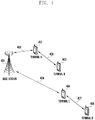
- FIG. 1 is a diagram illustrating a wireless mobile communication system supporting D2D communication according to an embodiment of the present invention.
- a base station 101 schedules terminal A 103 (user equipment (UE) or mobile station (MS)) and terminal B 104 located within a cell 102 hosted by the base station 101.
- the expression that the base station 101 schedules the terminal A 103 and the terminal B 104 may include the meaning that the base station provides the terminal with a radio access service.
- the terminal A 103 may perform cellular communication with the base station 101 through a terminal-base station link 106.
- the UE B 104 may perform cellular communication with the base station 101 through another terminal-base station link 107.
- the cellular communication may include communication of signals between a base station and a terminal. If the terminal A 103 and the terminal B 104 are D2D-enabled terminals, they may perform the discovery operation or direct communication operation through a D2D link 105 without assistance of the base station 101.
- the D2D communication technology being adopted in a cellular mobile communication system such as an LTE-A system should be designed so that it does not have a negative impact on the legacy cellular communication terminals.
- An embodiment of the present invention is directed to a technique of allocating separate radio resources to cellular terminals (in the present invention, the term "cellular terminal” is used to meana terminal supporting only the legacy base station-assisted communication and not the D2D communication) and D2D terminals as a method for avoiding mutual interference between D2D and cellular terminals.
- cellular terminal is used to mean a terminal supporting only the legacy base station-assisted communication and not the D2D communication
- D2D terminals as a method for avoiding mutual interference between D2D and cellular terminals.
- An LTE or LTE-A system may adopt frequency division duplexing (FDD) as its duplexing mode in which uplink (UL) and downlink (DL) are separated in frequency.
- FDD frequency division duplexing
- the DL and UL transmissions are separated in the frequency domain.
- D2D communication into a cellular system operating in the FDD mode, it is preferable to use the UL resources for D2D communication. This is because it is more difficult, in an FDD system, to allocate the downlink resources into which more types of signals are multiplexed than the uplink resources for the purpose of D2D communication.
- the next question is how to distinguish between legacy cellular communication and D2D communication resources.
- the legacy cellular communication resources and D2D communication resources may be allocated in an orthogonal multiplexing scheme such as time division multiplexing (TDM) and frequency division multiplexing (FDM) or in a non-orthogonal multiplexing scheme reusing the same resources.
- TDM time division multiplexing
- FDM frequency division multiplexing
- the D2D communication should be designed so that it does not have a negative impact on the legacy cellular communication terminals and, in this respect, the orthogonal multiplexing scheme is preferable.
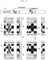
- FIG. 2 is a diagram illustrating a principle of multiplexing D2D signal transmission resources and cellular signal transmission resources according to an embodiment of the present invention.
- reference number 201 denotes regular subframes
- reference numbers 202 and 203 denote D2D subframes.
- a D2D signal may be transmitted in preconfigured subframes but may not be transmitted in all subframes.
- it may also be possible to configure even the subframes allocated for D2D signal transmission to convey physical uplink control channels (PUCCH) and physical uplink shared channels (PUSCH) for cellular communication. That is, the D2D signal transmission resources and legacy cellular signal transmission resources are multiplexed into a subframe configured for D2D transmission in the frequency domain.
- PUCCH physical uplink control channels
- PUSCH physical uplink shared channels
- the period 201 may be configured for use in cellular communication, and the periods 202 and 203 may be configured for use in D2D communication.
- the periods 202 and 203 may be referred to as D2D periods as denoted by reference number 205, and a D2D period occurrence interval may be referred to as a D2D cycle as denoted by reference number 204.
- D2D period is depicted as a set of consecutive subframes in FIG. 2 , the consecutiveness of the subframes is not mandatory; thus, it may also be configured with the D2D period as a set of non-consecutive subframes.
- the D2D signals are multiplexed into the at least one of the periods 202 and 203 with the length of the D2D period 205, and the D2D periods may include PUCCHs 207 and 208 carrying an HARQ acknowledgement (acknowledgement/negative acknowledgement (ACK/NACK) corresponding to DL cellular communication data) or channel quality indicator (CQI) as DL channel condition information and PUSCH 211 carrying UL cellular data.
- the PUCCHs may be arranged at both edges of the frequency band in the D2D period as denoted by reference numbers 207 and 208, and the PUSCH 211 may be arranged at the center of the frequency band.
- the D2D signals may be multiplexed into the D2D period 205 on the D2D resources 209 and 210, i.e., D2D resource blocks (DRBs) as a time-frequency region.
- D2D resource blocks D2D resource blocks
- the D2D resources are multiplexed into two regions 209 and 210 of one subframe to allocate PUSCH resources at the center of the frequency band as denoted by reference number 211; and, if no PUSCH resource exists, it may be possible to multiplex the D2D resources into one region.
- one DRB may be defined as an arbitrary size of a time-frequency resource unit, and it may be possible to multiplex a plurality of DRBs into a D2D period in a shape of a grid.
- one DRB may be defined as being composed of one subframe and 24 subcarriers (i.e., two RBs) that is identical with two physical resource blocks (PRBs).
- An arbitrary terminal may transmit its D2D signals in one of the multiplexed DRBs.
- the terminal may transmit a discovery signal once every D2D period. It may also be possible to transmit the discovery signal multiple times, but in the present invention it is assumed that the terminal transmits the D2D discovery signal once during one D2D period to facilitate the technique. Then, the discovery signal is transmitted again during the next D2D period.
- the discovery signal transmission resource position may be selected by the terminal arbitrarily, randomly, or according to an arbitrary rule.
- the terminal may determine a DRB for use in transmitting the discovery signal according to an arbitrary or predetermined rule and transmit the discovery signal on the determined DRB.
- terminal 1 may transmit its discovery signal on the DRB 211
- terminal 2 may transmit its discovery signal on the DRB 212
- terminal 3 may transmit its discovery signal on the DRB 213
- terminal 4 may transmit its discovery signal on the DRB 214.
- the terminals may be mapped to DRBs in a relative manner.
- terminals 1 to 4 transmit their discovery signals in the same time period (same subframe)
- none of the terminals can receive the discovery signals transmitted by others. That is, terminal 1 cannot receive the discovery signals transmitted by terminals 2 to 4; terminal 2 cannot receive the discovery signals transmitted by terminals 1, 3, and 4; terminal 3 cannot receive the discovery signals transmitted by terminals 1, 2, and 4; and terminal 4 cannot receive the discovery signals transmitted by terminals 1 to 3.
- use of a time-frequency hopping scheme in which the DRB position changes every discovery period may be considered.
- each of the terminals 1 to 4 may receive the discovery signals transmitted by the other terminals.
- the time-frequency hopping scheme may be determined according to at least one of a method configured to the terminal and a method indicated in a message received from the base station.
- a D2D terminal transmits a D2D signal on one DRB.
- the signal transmission is performed with an arbitrary frequency block in the whole frequency band
- an arbitrary transmit power with a relative value of the transmit power on the frequency block may occur outside the frequency block. This is called band re-emission power.
- terminal 1 transmits its discovery signal at 23 dBm on the DRB 1 211, a power of -7 dBm that differs as much as 30 dB from the transmit power on DRB 1 appears on other DRBs in the same subframe, which may cause additional noise or an interference effect to other terminals transmitting and receiving signals on the corresponding regions.
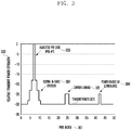
- a description is made of the properties of the in-band emission power hereinafter with reference to FIG. 3 .
- FIG. 3 is a diagram illustrating emission power when a terminal transmits a signal.
- FIG. 3 depicts how the in-band emission power appears in the whole band.
- FIG. 3 shows a value as a requirement of the in-band emission power, which should be less than the appeared value in an embodiment of the present invention; and, if being applied in reality, the in-band emission power may have the same value as shown in the drawing.
- the horizontal axis 301 denotes the PRB index, i.e., frequency
- the vertical axis 302 denotes the relative size of transmit power.
- a transmit power of -30 dB occurs across the whole band as denoted by reference number 307, and transmit powers that are greater than -30 dB are formed on 2 or 3 PRBs around the allocated frequency as denoted by reference number 304 (in detail, the transmit powers on the 2 or 3 PRBs around the allocated frequency may be formed in a stepwise manner.) This is referred to as in-band emission.
- an extra emission power caused by carrier leakage appears on at least one of the PRBs # 24 and #25 located at the center of the whole band; thus, the transmit power increases to become greater than -30 dB.
- an extra emission power caused by IQ imbalance may appear on the image frequencies of the allocated frequency that are located at positions symmetric around the center frequency; thus. the transmit power increases to become greater than -30 dB as denoted by reference number 306.
- the allocated frequency is PRB #7, the extra emission power caused by IQ imbalance appears on PRB #42.
- the first method is to determine the D2D signal transmit power in consideration of the distance from a base station.
- FIG. 4 is a diagram illustrating the first method according to the present invention. It is assumed that D2D terminals A to D 402, 403, 404, and 405 are located within the signal transmission range of a base station 401; the terminal A 402 located closest to the base station sends a D2D signal to the terminal B 403; and the terminal C 404 located farthest from the base station sends the D2D signal to the terminal D 405.
- the influence of the D2D signals transmitted by the terminal A 402 and the terminal C 404 to the base station may be considered.
- a signal transmitted by a terminal located close to the base station arrives at the base station at a high-power level; thus, the in-band emission power caused by the signal may contribute to an increase of noise to a cellular signal transmission.
- the terminals located far from the base station although they transmit signals at transmit power levels higher than those of the terminals located close to the base station, the contribution of the in-band emission power caused by the signals arriving at the base station to the increase of noise to the cellular signal transmission is negligible.
- the D2D signal transmit power level this may cause a problem of a service quality change according to the position of the terminal.
- the second method is to determine the D2D signal transmit power in such a way of sorting D2D terminals into groups by distance from a base station and allocating D2D resources by group in a time division multiplexing manner.
- FIG. 5 depicts a method of grouping terminals to allocate resources.
- Reference number 501 denotes regular sub frames
- reference numbers 502 and 503 denote D2D subframes.
- a D2D signal may be transmitted in preconfigured subframes but may not be transmitted in all subframes.
- it may also be possible to configure even the subframes allocated for D2D signal transmission to convey PUCCH and PUSCH for cellular communication. That is, the D2D signal transmission resources and legacy cellular signal transmission resources are multiplexed into a subframe configured for D2D transmission in the frequency domain.
- the period 501 may be configured for use in cellular communication
- the periods 502 and 503 may be configured for use in D2D communication.
- the D2D signals are multiplexed into the at least one of the periods 502 and 503 with the length of the D2D period 505, and the D2D periods may include PUCCHs 507 and 508 carrying an HARQ acknowledgement or CQI as DL channel condition information and PUSCH 511 carrying UL cellular data.
- the PUCCHs may be arranged at both edges of the frequency band in the D2D period as denoted by reference numbers 507 and 508, and the PUSCH 511 may be arranged at the center of the frequency band.
- the D2D signals may be multiplexed into the D2D period 505 on the D2D resources 509 and 510, i.e., D2D resource blocks (DRBs) are multiplexed into a time-frequency region.
- DRBs D2D resource blocks
- one DRB may be defined as an arbitrary size of a time-frequency resource unit, and it may be possible to multiplex a plurality of DRBs into a D2D period in a shape of a grid.
- the terminal may transmit a discovery signal every D2D at a resource position selected randomly or according to an arbitrary rule.
- the terminal may belong to a group generated based on the distance from the base station.
- the distance between the base station and the terminal may be determined using the value of a received signal received power (RSRP) measured by the terminal on the basis of the signal transmitted by the base station, and the terminal determines the group to which it belongs based on the currently measured RSRP.
- RSRP received signal received power
- FIG. 5 depicts two resource regions 520 and 530 corresponding to each of two terminal groups, i.e., lightly shaded resource region 520 and darkly shaded resource region 530, the number of groups may be greater than 2.
- Each group may be configured with a maximum value and a minimum value of RSRP for sorting a terminal into the group, e.g., group 520 with an RSRP range of ⁇ -infinity, -100 dBm ⁇ and group 530 with an RSRP range of ⁇ -100 dBm, +infinity ⁇ .
- SIB system information block
- a terminal of which the RSRP is less than -100 dBm is sorted into the group allocated the resource region 520, and a terminal of which the RSRP is greater than -100 dBm is sorted into the group allocated the resource region 530.
- a terminal belonging to one group transmits its D2D discovery signal on the resources allocated to the group, i.e., the lightly shaded resource region 520 in FIG. 5
- a terminal belong to the other group transmits its discovery signal on the resources allocated to the other group, i.e., the darkly shaded resource region 530 in FIG. 5 .
- terminals are grouped based on the RSRP to allocate the resources of the resource region 530 to the terminals close to the base station and the resource of the resource region 520 to the terminals far from the base station.
- the in-band emission power caused by D2D signal transmission on the PUCCH resource 521 and PUSCH resource 522 that are frequency-multiplexed with the D2D transmission resource for use by the terminals belonging to the group allocated the resource region 520 is so low as to cause little noise to cellular signal transmission.
- the in-band emission power caused by D2D signal transmission on the PUCCH resource 531 and PUSCH resource 532 that are frequency-multiplexed with the D2D transmission resource for use by the terminals belonging to the group allocated the resource region 530 is so high as to cause significant noiseto cellular signal transmission.
- This D2D discovery terminal grouping method is advantageous in terms of reducing the impact of D2D signal transmission to the cellular signal transmission as much as possible by gathering together D2D transmission resources for use by the terminals causing significant in-band emission power impact to the base station.
- the present invention proposes a method for reducing the impact of D2D signal transmission to cellular signal transmission in such a way that the base station performs physical downlink shared channel (PDSCH) and PUSCH scheduling dynamically based on D2D terminal group information.
- PDSCH physical downlink shared channel
- PUSCH PUSCH scheduling dynamically based on D2D terminal group information.
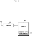
- FIG. 8 is a block diagram illustrating a configuration of a base station according to an embodiment of the present invention.
- the base station of the present invention may include a transceiver 810 and a controller 820.
- the transceiver 810 may transmit and receive signals to and from arbitrary nodes through wired or wireless interfaces in a wireless communication system.
- the transceiver 810 may transmit and receive control information or data to and from a terminal through a wireless interface.
- the controller 820 controls signal flows among function blocks for the operation of the base station.
- the controller 820 may control the control information or data transmission over PUCCH and PUSCH resources frequency-multiplexed with D2D signal transmission resources according to the method proposed in the above embodiments.
- the controller may include a base station-related information manager 821 and, in this case, the base station-related information manager 821 may control the control information or data transmission.
- the controller 820 may interpret PUCCH in different ways.
- the present invention is advantageous in terms of minimizing interference of D2D communication to cellular communication by differentiate resources and maintaining cellular communication throughput through enhanced scheduling and power control of the base station on the resources vulnerable to interference.
Landscapes
- Engineering & Computer Science (AREA)
- Signal Processing (AREA)
- Computer Networks & Wireless Communication (AREA)
- Quality & Reliability (AREA)
- Databases & Information Systems (AREA)
- Physics & Mathematics (AREA)
- Electromagnetism (AREA)
- Mobile Radio Communication Systems (AREA)
Applications Claiming Priority (2)
| Application Number | Priority Date | Filing Date | Title |
|---|---|---|---|
| KR1020150184158A KR102514908B1 (ko) | 2015-12-22 | 2015-12-22 | 무선 통신 시스템의 d2d 신호 전송 지원을 위한 기지국 동작 방법 및 장치 |
| PCT/KR2016/014920 WO2017111421A1 (ko) | 2015-12-22 | 2016-12-20 | 무선 통신 시스템의 d2d 신호 전송 지원을 위한 기지국 동작 방법 및 장치 |
Publications (3)
| Publication Number | Publication Date |
|---|---|
| EP3379751A1 true EP3379751A1 (de) | 2018-09-26 |
| EP3379751A4 EP3379751A4 (de) | 2019-04-17 |
| EP3379751B1 EP3379751B1 (de) | 2021-08-25 |
Family
ID=59089560
Family Applications (1)
| Application Number | Title | Priority Date | Filing Date |
|---|---|---|---|
| EP16879288.5A Active EP3379751B1 (de) | 2015-12-22 | 2016-12-20 | Basisstationsbetriebsverfahren und vorrichtung zur unterstützung von signalübertragung von vorrichtung zu vorrichtung in einem drahtloskommunikationssystem |
Country Status (4)
| Country | Link |
|---|---|
| US (1) | US10728908B2 (de) |
| EP (1) | EP3379751B1 (de) |
| KR (1) | KR102514908B1 (de) |
| WO (1) | WO2017111421A1 (de) |
Families Citing this family (5)
| Publication number | Priority date | Publication date | Assignee | Title |
|---|---|---|---|---|
| EP3457798B1 (de) * | 2016-05-30 | 2020-09-16 | Huawei Technologies Co., Ltd. | Datenübertragungsverfahren und vorrichtung |
| WO2019028801A1 (zh) * | 2017-08-10 | 2019-02-14 | 华为技术有限公司 | 一种信号发送、接收方法及装置 |
| US11659542B2 (en) * | 2017-12-14 | 2023-05-23 | Telefonaktiebolaget Lm Ericsson (Publ) | Scheduling of a data transmission |
| CN111132082B (zh) * | 2018-11-01 | 2020-12-08 | 电信科学技术研究院有限公司 | 一种资源选择方法、数据发送方法及装置 |
| CN116367332B (zh) * | 2023-05-31 | 2023-09-15 | 华信咨询设计研究院有限公司 | 一种5g系统下基于分级控制的d2d资源分配方法 |
Family Cites Families (13)
| Publication number | Priority date | Publication date | Assignee | Title |
|---|---|---|---|---|
| US9516638B2 (en) | 2012-06-20 | 2016-12-06 | Lg Electronics Inc. | Signal transmission/reception method and apparatus therefor |
| WO2013191518A1 (ko) | 2012-06-22 | 2013-12-27 | 엘지전자 주식회사 | 기기-대-기기 통신을 위한 스케줄링 방법 및 이를 위한 장치 |
| US20150208453A1 (en) * | 2012-07-27 | 2015-07-23 | Kyocera Corporation | Mobile communication system |
| US8982895B2 (en) | 2012-09-21 | 2015-03-17 | Blackberry Limited | Inter-device communication in wireless communication systems |
| US9894688B2 (en) | 2013-03-07 | 2018-02-13 | Lg Electronics Inc. | Method and apparatus for transmitting/receiving signal related to device-to-device communication in wireless communication system |
| US9306721B2 (en) * | 2013-03-15 | 2016-04-05 | Google Technology Holdings LLC | Method and apparatus for device-to-device communication |
| CN105981317B (zh) | 2013-10-08 | 2019-06-07 | 华为技术有限公司 | 避免开放发现与蜂窝资源之间的冲突的方法 |
| CN104601300B (zh) * | 2013-10-31 | 2018-03-16 | 电信科学技术研究院 | 一种数据传输方法及设备 |
| US9264968B2 (en) | 2013-12-03 | 2016-02-16 | Apple Inc. | Device to device communications with carrier aggregation |
| WO2015088293A1 (en) | 2013-12-13 | 2015-06-18 | Samsung Electronics Co., Ltd. | Apparatus and method for collision avoidance between hybrid automatic repeat request transmission and device to device transmission in communication system supporting device to device scheme |
| US10517070B2 (en) * | 2014-10-31 | 2019-12-24 | Lg Electronics Inc. | Method and devices for selecting transmission resource in wireless access system supporting non-licensed band |
| JP6626846B2 (ja) * | 2015-01-28 | 2019-12-25 | 京セラ株式会社 | ユーザ端末、基地局、及び方法 |
| US20170223695A1 (en) * | 2016-02-03 | 2017-08-03 | Lg Electronics Inc. | Method and apparatus for transmitting an uplink channel in a wireless communication system |
-
2015
- 2015-12-22 KR KR1020150184158A patent/KR102514908B1/ko active IP Right Grant
-
2016
- 2016-12-20 WO PCT/KR2016/014920 patent/WO2017111421A1/ko active Application Filing
- 2016-12-20 EP EP16879288.5A patent/EP3379751B1/de active Active
- 2016-12-20 US US16/065,685 patent/US10728908B2/en active Active
Also Published As
| Publication number | Publication date |
|---|---|
| KR102514908B1 (ko) | 2023-03-28 |
| WO2017111421A1 (ko) | 2017-06-29 |
| US20190007951A1 (en) | 2019-01-03 |
| EP3379751A4 (de) | 2019-04-17 |
| KR20170074636A (ko) | 2017-06-30 |
| US10728908B2 (en) | 2020-07-28 |
| EP3379751B1 (de) | 2021-08-25 |
Similar Documents
| Publication | Publication Date | Title |
|---|---|---|
| CN109923811B (zh) | 物理下行链路共享信道中的下行链路控制信息捎带 | |
| EP2947806B1 (de) | Datenübertragungs-/-empfangsverfahren und -vorrichtung eines kostengünstigen endgeräts in mobilkommunikationssystem | |
| US11323229B2 (en) | Method and device for determining uplink data and control signal transmission timing in wireless communication system | |
| EP3213427B1 (de) | Übertragung von harq-ack in kombiniert fdd- und tdd-trägeraggregation | |
| KR20190014915A (ko) | 무선 통신 시스템에서 하향링크 제어정보를 송수신하는 방법 및 장치 | |
| CN115088331A (zh) | 用于侧链路的资源选择 | |
| US10728908B2 (en) | Base station operation method and device for supporting D2D signal transmission in wireless communication system | |
| KR102359788B1 (ko) | 광대역 서비스를 제공하는 무선통신 시스템에서 스케쥴링 방법 및 장치 | |
| KR20170012153A (ko) | 협대역 시스템에서 통신 방법 및 장치 | |
| KR20220148180A (ko) | 업링크와 다운링크 사이의 레이트 매칭 | |
| US20210037552A1 (en) | Transmission batch scheduling and resource management | |
| CN116034556A (zh) | 用于物理侧行链路反馈信道上的调度请求的资源映射 | |
| CN115428385A (zh) | 用于调整时隙格式的信令 | |
| CN116018871A (zh) | 联合学习中用于空中模型聚集的资源分配 | |
| WO2022027421A1 (en) | Downlink control information for unicast scheduling of multiple user equipment | |
| KR20230157300A (ko) | 무선 통신 시스템에서 사운딩 참조 신호의 전송을 위한디폴트 빔 및 경로 손실 참조 신호를 선택하기 위한 방법 및 장치 | |
| US11533739B2 (en) | Method and apparatus for transmitting control and data signals based on a short TTI in a wireless cellular communication system | |
| US20230224900A1 (en) | Techniques for enhanced sidelink feedback transmission | |
| KR102480931B1 (ko) | 무선 통신 시스템에서 데이터채널을 송수신하는 방법 및 장치 | |
| TW202135496A (zh) | 基於回饋傳輸的上行鏈路許可 | |
| CN116982284A (zh) | 用于控制信道重复的搜索空间共享的技术 | |
| CN117083825A (zh) | 推迟的半持久调度反馈的按需传输 | |
| KR20180053174A (ko) | Mu-mimo를 지원하는 무선 통신 시스템에서 제어 정보를 송수신하는 방법 및 장치 | |
| KR20170033752A (ko) | Mtc 단말을 위한 피드백 제어 정보 송수신 방법 및 장치 |
Legal Events
| Date | Code | Title | Description |
|---|---|---|---|
| STAA | Information on the status of an ep patent application or granted ep patent |
Free format text: STATUS: THE INTERNATIONAL PUBLICATION HAS BEEN MADE |
|
| PUAI | Public reference made under article 153(3) epc to a published international application that has entered the european phase |
Free format text: ORIGINAL CODE: 0009012 |
|
| STAA | Information on the status of an ep patent application or granted ep patent |
Free format text: STATUS: REQUEST FOR EXAMINATION WAS MADE |
|
| 17P | Request for examination filed |
Effective date: 20180619 |
|
| AK | Designated contracting states |
Kind code of ref document: A1 Designated state(s): AL AT BE BG CH CY CZ DE DK EE ES FI FR GB GR HR HU IE IS IT LI LT LU LV MC MK MT NL NO PL PT RO RS SE SI SK SM TR |
|
| AX | Request for extension of the european patent |
Extension state: BA ME |
|
| RIC1 | Information provided on ipc code assigned before grant |
Ipc: H04L 1/20 20060101ALI20181106BHEP Ipc: H04L 5/00 20060101ALI20181106BHEP Ipc: H04L 1/18 20060101AFI20181106BHEP Ipc: H04L 1/16 20060101ALI20181106BHEP Ipc: H04L 1/00 20060101ALI20181106BHEP |
|
| DAV | Request for validation of the european patent (deleted) | ||
| DAX | Request for extension of the european patent (deleted) | ||
| A4 | Supplementary search report drawn up and despatched |
Effective date: 20190319 |
|
| RIC1 | Information provided on ipc code assigned before grant |
Ipc: H04L 1/20 20060101ALI20190313BHEP Ipc: H04L 1/18 20060101AFI20190313BHEP Ipc: H04L 5/00 20060101ALI20190313BHEP Ipc: H04L 1/16 20060101ALI20190313BHEP Ipc: H04L 1/00 20060101ALI20190313BHEP |
|
| GRAP | Despatch of communication of intention to grant a patent |
Free format text: ORIGINAL CODE: EPIDOSNIGR1 |
|
| STAA | Information on the status of an ep patent application or granted ep patent |
Free format text: STATUS: GRANT OF PATENT IS INTENDED |
|
| INTG | Intention to grant announced |
Effective date: 20210325 |
|
| GRAS | Grant fee paid |
Free format text: ORIGINAL CODE: EPIDOSNIGR3 |
|
| GRAA | (expected) grant |
Free format text: ORIGINAL CODE: 0009210 |
|
| STAA | Information on the status of an ep patent application or granted ep patent |
Free format text: STATUS: THE PATENT HAS BEEN GRANTED |
|
| AK | Designated contracting states |
Kind code of ref document: B1 Designated state(s): AL AT BE BG CH CY CZ DE DK EE ES FI FR GB GR HR HU IE IS IT LI LT LU LV MC MK MT NL NO PL PT RO RS SE SI SK SM TR |
|
| REG | Reference to a national code |
Ref country code: CH Ref legal event code: EP |
|
| REG | Reference to a national code |
Ref country code: IE Ref legal event code: FG4D Ref country code: AT Ref legal event code: REF Ref document number: 1424900 Country of ref document: AT Kind code of ref document: T Effective date: 20210915 |
|
| REG | Reference to a national code |
Ref country code: DE Ref legal event code: R096 Ref document number: 602016062889 Country of ref document: DE |
|
| REG | Reference to a national code |
Ref country code: LT Ref legal event code: MG9D |
|
| REG | Reference to a national code |
Ref country code: NL Ref legal event code: MP Effective date: 20210825 |
|
| REG | Reference to a national code |
Ref country code: AT Ref legal event code: MK05 Ref document number: 1424900 Country of ref document: AT Kind code of ref document: T Effective date: 20210825 |
|
| PG25 | Lapsed in a contracting state [announced via postgrant information from national office to epo] |
Ref country code: BG Free format text: LAPSE BECAUSE OF FAILURE TO SUBMIT A TRANSLATION OF THE DESCRIPTION OR TO PAY THE FEE WITHIN THE PRESCRIBED TIME-LIMIT Effective date: 20211125 Ref country code: AT Free format text: LAPSE BECAUSE OF FAILURE TO SUBMIT A TRANSLATION OF THE DESCRIPTION OR TO PAY THE FEE WITHIN THE PRESCRIBED TIME-LIMIT Effective date: 20210825 Ref country code: LT Free format text: LAPSE BECAUSE OF FAILURE TO SUBMIT A TRANSLATION OF THE DESCRIPTION OR TO PAY THE FEE WITHIN THE PRESCRIBED TIME-LIMIT Effective date: 20210825 Ref country code: NO Free format text: LAPSE BECAUSE OF FAILURE TO SUBMIT A TRANSLATION OF THE DESCRIPTION OR TO PAY THE FEE WITHIN THE PRESCRIBED TIME-LIMIT Effective date: 20211125 Ref country code: PT Free format text: LAPSE BECAUSE OF FAILURE TO SUBMIT A TRANSLATION OF THE DESCRIPTION OR TO PAY THE FEE WITHIN THE PRESCRIBED TIME-LIMIT Effective date: 20211227 Ref country code: ES Free format text: LAPSE BECAUSE OF FAILURE TO SUBMIT A TRANSLATION OF THE DESCRIPTION OR TO PAY THE FEE WITHIN THE PRESCRIBED TIME-LIMIT Effective date: 20210825 Ref country code: FI Free format text: LAPSE BECAUSE OF FAILURE TO SUBMIT A TRANSLATION OF THE DESCRIPTION OR TO PAY THE FEE WITHIN THE PRESCRIBED TIME-LIMIT Effective date: 20210825 Ref country code: HR Free format text: LAPSE BECAUSE OF FAILURE TO SUBMIT A TRANSLATION OF THE DESCRIPTION OR TO PAY THE FEE WITHIN THE PRESCRIBED TIME-LIMIT Effective date: 20210825 Ref country code: SE Free format text: LAPSE BECAUSE OF FAILURE TO SUBMIT A TRANSLATION OF THE DESCRIPTION OR TO PAY THE FEE WITHIN THE PRESCRIBED TIME-LIMIT Effective date: 20210825 Ref country code: RS Free format text: LAPSE BECAUSE OF FAILURE TO SUBMIT A TRANSLATION OF THE DESCRIPTION OR TO PAY THE FEE WITHIN THE PRESCRIBED TIME-LIMIT Effective date: 20210825 |
|
| PG25 | Lapsed in a contracting state [announced via postgrant information from national office to epo] |
Ref country code: PL Free format text: LAPSE BECAUSE OF FAILURE TO SUBMIT A TRANSLATION OF THE DESCRIPTION OR TO PAY THE FEE WITHIN THE PRESCRIBED TIME-LIMIT Effective date: 20210825 Ref country code: LV Free format text: LAPSE BECAUSE OF FAILURE TO SUBMIT A TRANSLATION OF THE DESCRIPTION OR TO PAY THE FEE WITHIN THE PRESCRIBED TIME-LIMIT Effective date: 20210825 Ref country code: GR Free format text: LAPSE BECAUSE OF FAILURE TO SUBMIT A TRANSLATION OF THE DESCRIPTION OR TO PAY THE FEE WITHIN THE PRESCRIBED TIME-LIMIT Effective date: 20211126 |
|
| PG25 | Lapsed in a contracting state [announced via postgrant information from national office to epo] |
Ref country code: NL Free format text: LAPSE BECAUSE OF FAILURE TO SUBMIT A TRANSLATION OF THE DESCRIPTION OR TO PAY THE FEE WITHIN THE PRESCRIBED TIME-LIMIT Effective date: 20210825 |
|
| PG25 | Lapsed in a contracting state [announced via postgrant information from national office to epo] |
Ref country code: DK Free format text: LAPSE BECAUSE OF FAILURE TO SUBMIT A TRANSLATION OF THE DESCRIPTION OR TO PAY THE FEE WITHIN THE PRESCRIBED TIME-LIMIT Effective date: 20210825 |
|
| REG | Reference to a national code |
Ref country code: DE Ref legal event code: R097 Ref document number: 602016062889 Country of ref document: DE |
|
| PG25 | Lapsed in a contracting state [announced via postgrant information from national office to epo] |
Ref country code: SM Free format text: LAPSE BECAUSE OF FAILURE TO SUBMIT A TRANSLATION OF THE DESCRIPTION OR TO PAY THE FEE WITHIN THE PRESCRIBED TIME-LIMIT Effective date: 20210825 Ref country code: SK Free format text: LAPSE BECAUSE OF FAILURE TO SUBMIT A TRANSLATION OF THE DESCRIPTION OR TO PAY THE FEE WITHIN THE PRESCRIBED TIME-LIMIT Effective date: 20210825 Ref country code: RO Free format text: LAPSE BECAUSE OF FAILURE TO SUBMIT A TRANSLATION OF THE DESCRIPTION OR TO PAY THE FEE WITHIN THE PRESCRIBED TIME-LIMIT Effective date: 20210825 Ref country code: EE Free format text: LAPSE BECAUSE OF FAILURE TO SUBMIT A TRANSLATION OF THE DESCRIPTION OR TO PAY THE FEE WITHIN THE PRESCRIBED TIME-LIMIT Effective date: 20210825 Ref country code: CZ Free format text: LAPSE BECAUSE OF FAILURE TO SUBMIT A TRANSLATION OF THE DESCRIPTION OR TO PAY THE FEE WITHIN THE PRESCRIBED TIME-LIMIT Effective date: 20210825 Ref country code: AL Free format text: LAPSE BECAUSE OF FAILURE TO SUBMIT A TRANSLATION OF THE DESCRIPTION OR TO PAY THE FEE WITHIN THE PRESCRIBED TIME-LIMIT Effective date: 20210825 |
|
| PLBE | No opposition filed within time limit |
Free format text: ORIGINAL CODE: 0009261 |
|
| STAA | Information on the status of an ep patent application or granted ep patent |
Free format text: STATUS: NO OPPOSITION FILED WITHIN TIME LIMIT |
|
| PG25 | Lapsed in a contracting state [announced via postgrant information from national office to epo] |
Ref country code: MC Free format text: LAPSE BECAUSE OF FAILURE TO SUBMIT A TRANSLATION OF THE DESCRIPTION OR TO PAY THE FEE WITHIN THE PRESCRIBED TIME-LIMIT Effective date: 20210825 Ref country code: IT Free format text: LAPSE BECAUSE OF FAILURE TO SUBMIT A TRANSLATION OF THE DESCRIPTION OR TO PAY THE FEE WITHIN THE PRESCRIBED TIME-LIMIT Effective date: 20210825 |
|
| REG | Reference to a national code |
Ref country code: CH Ref legal event code: PL |
|
| 26N | No opposition filed |
Effective date: 20220527 |
|
| PG25 | Lapsed in a contracting state [announced via postgrant information from national office to epo] |
Ref country code: SI Free format text: LAPSE BECAUSE OF FAILURE TO SUBMIT A TRANSLATION OF THE DESCRIPTION OR TO PAY THE FEE WITHIN THE PRESCRIBED TIME-LIMIT Effective date: 20210825 |
|
| REG | Reference to a national code |
Ref country code: BE Ref legal event code: MM Effective date: 20211231 |
|
| PG25 | Lapsed in a contracting state [announced via postgrant information from national office to epo] |
Ref country code: LU Free format text: LAPSE BECAUSE OF NON-PAYMENT OF DUE FEES Effective date: 20211220 Ref country code: IE Free format text: LAPSE BECAUSE OF NON-PAYMENT OF DUE FEES Effective date: 20211220 |
|
| PG25 | Lapsed in a contracting state [announced via postgrant information from national office to epo] |
Ref country code: FR Free format text: LAPSE BECAUSE OF NON-PAYMENT OF DUE FEES Effective date: 20211231 Ref country code: BE Free format text: LAPSE BECAUSE OF NON-PAYMENT OF DUE FEES Effective date: 20211231 |
|
| PG25 | Lapsed in a contracting state [announced via postgrant information from national office to epo] |
Ref country code: LI Free format text: LAPSE BECAUSE OF NON-PAYMENT OF DUE FEES Effective date: 20211231 Ref country code: CH Free format text: LAPSE BECAUSE OF NON-PAYMENT OF DUE FEES Effective date: 20211231 |
|
| PG25 | Lapsed in a contracting state [announced via postgrant information from national office to epo] |
Ref country code: HU Free format text: LAPSE BECAUSE OF FAILURE TO SUBMIT A TRANSLATION OF THE DESCRIPTION OR TO PAY THE FEE WITHIN THE PRESCRIBED TIME-LIMIT; INVALID AB INITIO Effective date: 20161220 |
|
| PG25 | Lapsed in a contracting state [announced via postgrant information from national office to epo] |
Ref country code: CY Free format text: LAPSE BECAUSE OF FAILURE TO SUBMIT A TRANSLATION OF THE DESCRIPTION OR TO PAY THE FEE WITHIN THE PRESCRIBED TIME-LIMIT Effective date: 20210825 |
|
| PGFP | Annual fee paid to national office [announced via postgrant information from national office to epo] |
Ref country code: GB Payment date: 20231120 Year of fee payment: 8 |
|
| PGFP | Annual fee paid to national office [announced via postgrant information from national office to epo] |
Ref country code: DE Payment date: 20231120 Year of fee payment: 8 |
|
| PG25 | Lapsed in a contracting state [announced via postgrant information from national office to epo] |
Ref country code: MK Free format text: LAPSE BECAUSE OF FAILURE TO SUBMIT A TRANSLATION OF THE DESCRIPTION OR TO PAY THE FEE WITHIN THE PRESCRIBED TIME-LIMIT Effective date: 20210825 |