EP3379651A1 - Kabelschuh - Google Patents
Kabelschuh Download PDFInfo
- Publication number
- EP3379651A1 EP3379651A1 EP17305337.2A EP17305337A EP3379651A1 EP 3379651 A1 EP3379651 A1 EP 3379651A1 EP 17305337 A EP17305337 A EP 17305337A EP 3379651 A1 EP3379651 A1 EP 3379651A1
- Authority
- EP
- European Patent Office
- Prior art keywords
- container
- conductor
- cable lug
- lug
- contact end
- Prior art date
- Legal status (The legal status is an assumption and is not a legal conclusion. Google has not performed a legal analysis and makes no representation as to the accuracy of the status listed.)
- Granted
Links
Images

Classifications
-
- H—ELECTRICITY
- H01—ELECTRIC ELEMENTS
- H01R—ELECTRICALLY-CONDUCTIVE CONNECTIONS; STRUCTURAL ASSOCIATIONS OF A PLURALITY OF MUTUALLY-INSULATED ELECTRICAL CONNECTING ELEMENTS; COUPLING DEVICES; CURRENT COLLECTORS
- H01R4/00—Electrically-conductive connections between two or more conductive members in direct contact, i.e. touching one another; Means for effecting or maintaining such contact; Electrically-conductive connections having two or more spaced connecting locations for conductors and using contact members penetrating insulation
- H01R4/10—Electrically-conductive connections between two or more conductive members in direct contact, i.e. touching one another; Means for effecting or maintaining such contact; Electrically-conductive connections having two or more spaced connecting locations for conductors and using contact members penetrating insulation effected solely by twisting, wrapping, bending, crimping, or other permanent deformation
- H01R4/18—Electrically-conductive connections between two or more conductive members in direct contact, i.e. touching one another; Means for effecting or maintaining such contact; Electrically-conductive connections having two or more spaced connecting locations for conductors and using contact members penetrating insulation effected solely by twisting, wrapping, bending, crimping, or other permanent deformation by crimping
- H01R4/187—Electrically-conductive connections between two or more conductive members in direct contact, i.e. touching one another; Means for effecting or maintaining such contact; Electrically-conductive connections having two or more spaced connecting locations for conductors and using contact members penetrating insulation effected solely by twisting, wrapping, bending, crimping, or other permanent deformation by crimping combined with soldering or welding
-
- H—ELECTRICITY
- H01—ELECTRIC ELEMENTS
- H01R—ELECTRICALLY-CONDUCTIVE CONNECTIONS; STRUCTURAL ASSOCIATIONS OF A PLURALITY OF MUTUALLY-INSULATED ELECTRICAL CONNECTING ELEMENTS; COUPLING DEVICES; CURRENT COLLECTORS
- H01R11/00—Individual connecting elements providing two or more spaced connecting locations for conductive members which are, or may be, thereby interconnected, e.g. end pieces for wires or cables supported by the wire or cable and having means for facilitating electrical connection to some other wire, terminal, or conductive member, blocks of binding posts
- H01R11/11—End pieces or tapping pieces for wires, supported by the wire and for facilitating electrical connection to some other wire, terminal or conductive member
- H01R11/12—End pieces terminating in an eye, hook, or fork
-
- H—ELECTRICITY
- H01—ELECTRIC ELEMENTS
- H01R—ELECTRICALLY-CONDUCTIVE CONNECTIONS; STRUCTURAL ASSOCIATIONS OF A PLURALITY OF MUTUALLY-INSULATED ELECTRICAL CONNECTING ELEMENTS; COUPLING DEVICES; CURRENT COLLECTORS
- H01R4/00—Electrically-conductive connections between two or more conductive members in direct contact, i.e. touching one another; Means for effecting or maintaining such contact; Electrically-conductive connections having two or more spaced connecting locations for conductors and using contact members penetrating insulation
- H01R4/10—Electrically-conductive connections between two or more conductive members in direct contact, i.e. touching one another; Means for effecting or maintaining such contact; Electrically-conductive connections having two or more spaced connecting locations for conductors and using contact members penetrating insulation effected solely by twisting, wrapping, bending, crimping, or other permanent deformation
- H01R4/18—Electrically-conductive connections between two or more conductive members in direct contact, i.e. touching one another; Means for effecting or maintaining such contact; Electrically-conductive connections having two or more spaced connecting locations for conductors and using contact members penetrating insulation effected solely by twisting, wrapping, bending, crimping, or other permanent deformation by crimping
- H01R4/20—Electrically-conductive connections between two or more conductive members in direct contact, i.e. touching one another; Means for effecting or maintaining such contact; Electrically-conductive connections having two or more spaced connecting locations for conductors and using contact members penetrating insulation effected solely by twisting, wrapping, bending, crimping, or other permanent deformation by crimping using a crimping sleeve
-
- H—ELECTRICITY
- H01—ELECTRIC ELEMENTS
- H01R—ELECTRICALLY-CONDUCTIVE CONNECTIONS; STRUCTURAL ASSOCIATIONS OF A PLURALITY OF MUTUALLY-INSULATED ELECTRICAL CONNECTING ELEMENTS; COUPLING DEVICES; CURRENT COLLECTORS
- H01R4/00—Electrically-conductive connections between two or more conductive members in direct contact, i.e. touching one another; Means for effecting or maintaining such contact; Electrically-conductive connections having two or more spaced connecting locations for conductors and using contact members penetrating insulation
- H01R4/58—Electrically-conductive connections between two or more conductive members in direct contact, i.e. touching one another; Means for effecting or maintaining such contact; Electrically-conductive connections having two or more spaced connecting locations for conductors and using contact members penetrating insulation characterised by the form or material of the contacting members
- H01R4/62—Connections between conductors of different materials; Connections between or with aluminium or steel-core aluminium conductors
- H01R4/625—Soldered or welded connections
Definitions
- the invention relates to a cable lug for connecting an insulated electrical conductor to a current-carrying element.
- electrical conductors such as stranded conductors
- contact elements made of electrically conductive material used. Electrical connections must be made between the voltage source, such as a battery, and actuators, sensors, controls, etc.
- the mentioned current-carrying elements are, for example, the terminals of a battery or bolt in the engine compartment of a motor vehicle, to which electrical conductors must be connected by means of cable lugs. In most cases these are flexible insulated stranded conductors.
- the cable lugs are metal elements which are adapted to be crimped and / or welded to a stripped conductor end. The conductor and the cable lugs are non-positively and / or materially connected to each other.
- FIG. 1 An example of a known cable lug is in Fig. 1 shown.
- the cable lug 1 has a contact end 2 for connection to the current-carrying element, to which the cable lug 1 is screwed, for example.
- the cable lug 1 has a receptacle 3 for a stripped end of the electrical conductor.
- the receptacle 3 has two pairs Crimpinatel 4, 5, which are crimped to the conductor end.
- the conductor end can also be welded to the cable lug 1.
- Electrical conductors made of copper are increasingly being replaced today by conductors made of aluminum or an aluminum alloy, in particular in the automotive industry.
- Aluminum is a lighter and cheaper material with good electrical properties than copper.
- the cable lugs are usually made of copper or a copper alloy.
- the stripped aluminum conductor must be freed before the electrical connection of the non-conductive oxide layer which forms when aluminum contacts with oxygen. This can be effected, for example, by welding the aluminum conductor to the cable lug.
- the welding has the further advantage that the conductor and the cable lug are materially interconnected, so that any cold flow of the aluminum has no effect on the quality of the connection.
- the weld is usually located directly at the junction of the cable lug on the current-carrying element.
- connection In particular for stranded conductors or battery cables with large cross sections, the mechanical stability of the connection with the cable lug is important.
- the connection must be resistant to vibrations and possible cold flow of the aluminum.
- the invention has for its object to provide a cable lug for an electrical conductor, which meets the requirements mentioned.
- the cable lug according to the invention is a dimensionally stable, conductive contact element for the transmission of current through the connection of an electrical conductor with a current-carrying element.
- the cable lug consists of two separate fasteners, namely the container and the contact end.
- the container serves to accommodate the conductor, which is flexible and movable.
- the contact end also referred to below as connection geometry, serves for fastening the cable lug to the current-carrying element, which is fixed.
- the cable lug is designed so that the conductor can be fixed thereto as desired by crimping and welding.
- connection geometry takes on the mounted by means of the cable lug connection between the electrical conductor and the current-carrying element all mechanical loads, such as vibrations or shocks in a motor vehicle.
- the transition element between the contact end and the receptacle is a spatial and functional separation of these two fasteners. Due to this spatial and functional separation, the method of attachment of the conductor has no influence on the geometry or the mechanical structure of the connection geometry, since the force and heat during fastening of the conductor end does not take place in the area of the contact end.
- the connection geometry can thus not be damaged. Therefore, it is ensured that the connection geometry permanently withstand mechanical stresses such as vibrations and shocks.
- the cable lug according to the invention is therefore extremely robust, and the connection between the cable end and the cable lug is protected against mechanical stresses which may occur during use of the same, and particularly durable.
- the cable lug can be designed so that the contacting geometry, i. the shape of the container, for the conductor always remains the same and the connection geometry of the application is carried out according to various types.
- the transition element can take various forms, which ensures the spatial and functional separation.
- the cable lug according to the invention can be advantageously used for conductors with large cross-sections, which must be contacted securely and consistently, for example in electric and hybrid vehicles and in mechanical and plant engineering.
- the invention further relates to a compound of an electrical conductor and a cable lug with the said properties.
- FIGS. 2 and 3 show a cable lug 10, 20 according to a first and a second embodiment of the invention.
- the cable lug 10, 20 has a tubular or pot-like container 11, which is closed at its bottom 11a.
- the container is substantially cylindrical.
- the container 11 may also have a conical shape tapering towards the bottom 2a, or other shapes suitable for receiving the conductor.
- the container 11 is to one side, the bottom 11 a opposite, open.
- an edge 11b Surrounding the opening of the container 11 is an edge 11b. Continuously from the edge 11b, a flat contact end 12 is attached by means of a transition element 14. By means of the contact end 12, the cable lug 10, 20 with an electrical element, such as a battery terminal or the body of a motor vehicle, are connected. For example, the cable lug 10, 20 are screwed to the electrical element, for which purpose a screw can be inserted through a hole or a hole 13 in the contact end 12.
- the transition element 14 has according to the first embodiment of Fig. 2 a bent in two directions form, which is followed by the contact end 12 consecutively.
- the transition element 14 has the shape of a web.
- the web consists of two flat parts 15, 16, which are connected by a ramp 17 with each other.
- the contact end 12 is disposed at an approximately right angle to the flat parts 15, 16 opposite the container 11.
- the shape of the transition element 14 can be adapted to the particular application requirements.
- the transition element 14 ensures that the connection geometry, ie the contact end 12, spatially and functionally separated from themaschinetechniksgeometrie, ie the container 11. A main axis of the container (11) and the contact end lie in different planes. Due to the transition element 14, the contact end 12 does not directly connect continuously to the receptacle 11 for the conductor end. The contact end 12 and the receptacle 11 are not designed in one piece, as for example in the known cable lug Fig. 1 ,
- the heat during welding is spatially independent of the contact end 12 of the cable lug.
- the weld, which is located advantageously on the bottom 11 a of the container 11 is therefore force-decoupled from the connection geometry.
- the container 11 is a receptacle for an electrical conductor to be connected to the cable lug 10, 20.
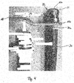
- a cable lug 20 according to the invention mounted on a stripped end 30a of a conductor 30 is shown in FIG Fig. 4 shown.
- the electrical conductor 30 is, for example, a stranded conductor made of aluminum.
- the stranded conductor 30 consists of a plurality of individual electrical conductors and is surrounded by insulation.
- the insulation consists for example of silicone or polyvinyl chloride.
- the cable lug 10, 20 can also accommodate other types of electrical conductors, such as single conductors.
- the stripped end 30 a of the stranded conductor 30 is inserted into the container 11 of the cable lug 20.
- the stripped part 30 a of the conductor 30 protrudes slightly out of the container 11.
- the container 11 may also completely cover the stripped end 30a.
- the container 11 is crimped to the stripped end 30 a of the conductor 30.
- the front side of the conductor 30 is welded to the bottom 11 a of the container 11 of the cable lug 20.
- the end of the insulation of the conductor can also extend, depending on the application of the compound, a little way into the container 11.
- the container 11 may be designed accordingly, for example with a conical shape.
- a rotationally symmetrical sealing element may be arranged (not shown), which seals the stripped conductor end from the environment.
- the container 11 preferably has a diameter that widens continuously or gradually from the bottom 11a to the edge 11b.
- the cable lug 10, 20 consists for example of copper or a copper alloy. It can furthermore have a surface coating, for example made of nickel or tin.
- the cable lug according to the invention can be manufactured in a few simple steps.
- the container can be produced for example in a deep-drawing process. This process is independent of the connection geometry.
- the inventive compound of the electrical conductor 30 with the cable lug 10, 20 can be prepared as follows.
- the end 30 a of the conductor 30 is stripped and inserted into the container 11 of the cable lug 10, 20.
- the front side of the conductor 30, which may consist of a plurality of strands, is guided to the bottom 11 a of the container 11.
- the cable lug 10, 20 is then non-positively by crimping the wall of the container 11 with the stripped conductor end 30a connected.
- the container 11 can be pressed at least partially into a hexagon.
- the end face of the conductor 30 is welded to the bottom 11 a of the container 11.
- the conductor 30 is now material and non-positively connected to the cable lug 10, 20.
- a sealing element can be pressed into the upper region of the container 11. This method of making the connection may advantageously be done in an automated manufacturing process or integrated therein.
Landscapes
- Connections Effected By Soldering, Adhesion, Or Permanent Deformation (AREA)
Abstract
Description
- Die Erfindung bezieht sich auf einen Kabelschuh zur Verbindung eines isolierten elektrischen Leiters mit einem stromführenden Element.
- Insbesondere in der Automobilelektronik kommt eine Vielzahl von elektrischen Leitern, beispielsweise Litzenleitern, und mit diesen verbundenen Kontaktelementen aus elektrisch leitendem Material zum Einsatz. Elektrische Verbindungen müssen zwischen der Spannungsquelle, beispielsweise einer Batterie, und Aktuatoren, Sensoren, Steuerelementen usw. hergestellt werden. Die erwähnten stromführenden Elemente sind beispielsweise die Anschlüsse einer Batterie oder Bolzen im Motorraum eines Kraftfahrzeugs, an welche elektrische Leiter mittels Kabelschuhen angeschlossen werden müssen. In den meisten Fällen handelt es sich dabei um flexible isolierte Litzenleiter. Die Kabelschuhe sind Elemente aus Metall, welche so beschaffen sind, daß sie an ein abisoliertes Leiterende gecrimpt und/oder mit diesem verschweißt werden können. Der Leiter und der Kabelschuhe werden dabei kraft- und/oder stoffschlüssig miteinander verbunden.
- Ein Beispiel eines bekannten Kabelschuhs ist in
Fig. 1 dargestellt. Der Kabelschuh 1 weist ein Kontaktende 2 zur Verbindung mit dem stromführenden Element auf, an welches der Kabelschuh 1 beispielsweise angeschraubt wird. An seinem anderen Ende hat der Kabelschuh 1 eine Aufnahme 3 für ein abisoliertes Ende des elektrischen Leiters. Im dargestellten Beispiel hat die Aufnahme 3 zwei Paar Crimpflügel 4, 5, die um das Leiterende gecrimpt werden. Das Leiterende kann auch mit dem Kabelschuh 1 verschweißt werden. - Elektrische Leiter aus Kupfer werden heute, insbesondere in der Automobilindustrie, zunehmend durch Leiter aus Aluminium oder einer Aluminium-Legierung ersetzt. Aluminium ist gegenüber Kupfer ein leichteres und preiswerteres Material mit guten elektrischen Eigenschaften. Die Kabelschuhe bestehen zumeist aus Kupfer oder einer Kupferlegierung. Um eine einwandfreie elektrisch leitende Verbindung zwischen einem Kabelschuh aus Kupfer und einem Aluminiumleiter herzustellen, muß der abisolierte Aluminiumleiter vor dem elektrischen Verbinden von der nichtleitenden Oxidschicht befreit werden, die sich beim Kontakt von Aluminium mit Sauerstoff bildet. Dies kann beispielsweise durch Verschweißen des Aluminiumleiters mit dem Kabelschuh bewirkt werden. Das Verschweißen hat weiterhin den Vorteil, daß der Leiter und der Kabelschuh stofflich miteinander verbunden sind, sodaß ein eventuelles Kaltfließen des Aluminiums keinen Einfluß auf die Qualität der Verbindung hat. Die Schweißstelle befindet sich zumeist direkt an der Anschlußstelle des Kabelschuhs am stromführenden Element.
- Insbesondere für Litzenleiter oder Batterieleitungen mit großen Querschnitten ist die mechanische Stabilität der Verbindung mit dem Kabelschuh von Bedeutung. Die Verbindung muß widerstandsfähig gegenüber Schwingungen und einem eventuellen Kaltfließen des Aluminiums sein.
- Der Erfindung liegt die Aufgabe zugrunde, einen Kabelschuh für einen elektrischen Leiter bereitzustellen, welcher die genannten Anforderungen erfüllt.
- Diese Aufgabe wird gemäß der Erfindung dadurch gelöst, daß
- die Aufnahme des Kabelschuhs einen topfartigen Behälter aufweist, und
- das Kontaktende des Kabelschuhs und der Behälter durch ein Übergangselement miteinander verbunden sind.
- Bei dem erfindungsgemäßen Kabelschuh handelt es sich um ein formstabiles, leitfähiges Kontaktelement für die Übertragung von Strom durch die Verbindung von einem elektrischen Leiter mit einem stromführenden Element. Der Kabelschuh besteht aus zwei voneinander getrennten Befestigungselementen, nämlich dem Behälter und dem Kontaktende. Der Behälter dient zur Aufnahme des Leiters, welcher flexible und beweglich ist. Das Kontaktende, im Folgenden auch Anschlußgeometrie genannt, dient zur Befestigung des Kabelschuhs an dem stromführenden Element, welches feststeht. Der Kabelschuh ist so gestaltet, daß der Leiter wie gewünscht durch Crimpen und Schweißen daran festgelegt werden kann. Diese beiden Befestigungsmethoden stellen sowohl die mechanische als auch die elektrische Verbindung des Leiters mit dem Kabelschuh sicher. Die Anschlußgeometrie nimmt bei der mittels des Kabelschuhs montierten Verbindung zwischen dem elektrischen Leiter und dem stromführenden Element sämtliche mechanischen Belastungen auf, beispielsweise Schwingungen oder Stöße in einem Kraftfahrzeug. Das Übergangselement zwischen dem Kontaktende und der Aufnahme stellt eine räumliche und funktionelle Trennung dieser beiden Befestigungselemente dar. Durch diese räumliche und funktionelle Trennung hat das Befestigungsverfahren des Leiters keinerlei Einfluß auf die Geometrie oder das mechanische Gefüge der Anschlußgeometrie, da die Kraft- und Wärmeeinwirkung beim Befestigen des Leiterendes nicht in dem Bereich des Kontaktendes stattfinden. Die Anschlußgeometrie kann somit nicht beschädigt werden. Daher ist sichergestellt, daß die Anschlußgeometrie auftretenden mechanischen Belastungen wie Schwingungen und Stößen dauerhaft standhält. Der erfindungsgemäße Kabelschuh ist deshalb äußerst robust, und die Verbindung zwischen dem Leitungsende und dem Kabelschuh ist vor mechanischen Belastungen, welche im Einsatz derselben auftreten können, geschützt und besonders haltbar.
- Der Kabelschuh kann so gestaltet werden, daß die Kontaktierungsgeometrie, d.h. die Form des Behälters, für den Leiter stets gleich bleibt und die Anschlußgeometrie der Anwendung entsprechend verschiedenartig ausgeführt ist.
- Das Übergangselement kann verschiedene Formen annehmen, durch welche die räumliche und funktionelle Trennung sichergestellt ist.
- Der erfindungsgemäße Kabelschuh kann mit Vorteil für Leiter mit großen Querschnitten eingesetzt werden, welche sicher und beständig kontaktiert werden müssen, beispielsweise in Elektro- und Hybridfahrzeugen und im Maschinen- und Anlagenbau.
- Die Erfindung betrifft weiterhin eine Verbindung aus einem elektrischen Leiter und einem Kabelschuh mit den genannten Eigenschaften.
- Ausführungsbeispiele des Erfindungsgegenstandes sind in den Zeichnungen dargestellt. Es zeigen:
-
Fig. 1 , wie bereits beschrieben, einen Kabelschuh nach dem Stand der Technik, -
Fig. 2 ein erstes Ausführungsbeispiel eines Kabelschuhs nach der Erfindung, -
Fig. 3 ein zweites Ausführungsbeispiel des Kabelschuhs nach der Erfindung, und -
Fig. 4 den Kabelschuh nach dem zweiten Ausführungsbeispiel in montiertem Zustand. - In den Zeichnungen beziehen sich gleiche Bezugszeichen auf gleiche technische Merkmale.
- Die
Fig. 2 und 3 zeigen einen Kabelschuh 10, 20 nach einer ersten bzw. einer zweiten Ausführungsform der Erfindung. - Der Kabelschuh 10, 20 weist einen rohr- oder topfartigen Behälter 11 auf, welcher an seinem Boden 11a geschlossen ist. In den dargestellten Beispielen ist der Behälter im Wesentlichen zylindrisch. Der Behälter 11 kann auch eine konische, sich zum Boden 2a hin verengende Form, oder andere, zur Leiteraufnahme geeignete Formen haben. Der Behälter 11 ist nach einer Seite, dem Boden 11 a gegenüberliegend, offen.
- Um die Öffnung des Behälters 11 umlaufend befindet sich ein Rand 11b. Von dem Rand 11b fortlaufend ist mittels eines Übergangselements 14 ein flaches Kontaktende 12 angebracht. Mittels des Kontaktendes 12 kann der Kabelschuh 10, 20 mit einem elektrischen Element, beispielsweise einer Batterieklemme oder der Karosserie eines Kraftfahrzeugs, verbunden werden. Beispielsweise kann der Kabelschuh 10, 20 an das elektrische Element geschraubt werden, wozu eine Schraube durch eine Bohrung bzw. ein Loch 13 in dem Kontaktende 12 gesteckt werden kann.
- Das Übergangselement 14 hat nach dem ersten Ausführungsbeispiel der
Fig. 2 eine in zwei Richtungen gebogene Form, an die sich fortlaufend das Kontaktende 12 anschließt. Nach dem zweiten Ausführungsbeispiel derFig. 3 und4 hat das Übergangselement 14 die Form eines Stegs. Der Steg besteht aus zwei flachen Teilen 15, 16, die mittels einer Rampe 17 miteinander verbunden sind. Das Kontaktende 12 ist in einem etwa rechten Winkel zu den flachen Teilen 15, 16 dem Behälter 11 gegenüberliegend angeordnet. Die Form des Übergangselements 14 kann den jeweiligen Anwendungsanforderungen angepaßt werden. - Das Übergangselement 14 sorgt dafür, daß die Anschlußgeometrie, d.h. das Kontaktende 12, räumlich und funktionell von der Kontaktierungsgeometrie, d.h. dem Behälter 11, getrennt ist. Eine Hauptachse des Behälters (11) und das Kontaktende liegen so in verschiedenen Ebenen. Durch das Übergangselement 14 schließt das Kontaktende 12 nicht direkt fortlaufend an die Aufnahme 11 für das Leiterende an. Das Kontaktende 12 und die Aufnahme 11 sind nicht einteilig gestaltet, wie beispielsweise bei dem bekannten Kabelschuh nach
Fig. 1 . - Insbesondere die Wärmeeinwirkung beim Schweißen ist räumlich unabhängig vom Kontaktende 12 des Kabelschuhs. Die Schweißstelle, welche sich mit Vorteil am Boden 11 a des Behälters 11 befindet, ist deshalb von der Anschlußgeometrie kraftentkoppelt.
- Der Behälter 11 stellt eine Aufnahme für einen mit dem Kabelschuh 10, 20 zu verbindenden elektrischen Leiter dar. Ein an einem abisolierten Ende 30a eines Leiters 30 montierter Kabelschuh 20 nach der Erfindung ist in
Fig. 4 gezeigt. Der elektrische Leiter 30 ist beispielsweise ein Litzenleiter aus Aluminium. Der Litzenleiter 30 besteht aus einer Vielzahl von elektrischen Einzelleitern und ist von einer Isolierung umgeben. Die Isolierung besteht beispielsweise aus Silikon oder Polyvinylchlorid. Der Kabelschuh 10, 20 kann allerdings auch andere Arten von elektrischen Leitern, beispielsweise Einzelleiter, aufnehmen. - Wie in
Fig. 4 dargestellt, ist das abisolierte Ende 30a des Litzenleiters 30 in den Behälter 11 des Kabelschuhs 20 eingesteckt. In dem gezeigten Beispiel ragt der abisolierte Teil 30a des Leiters 30 etwas aus dem Behälter 11 heraus. Der Behälter 11 kann das abisolierte Ende 30a allerdings auch vollständig bedecken. Der Behälter 11 ist an das abisolierte Ende 30a des Leiters 30 gecrimpt. Die Stirnseite des Leiters 30 ist am Boden 11a des Behälters 11 des Kabelschuhs 20 angeschweißt. - Das Ende der Isolierung des Leiters kann auch, je nach Anwendung der Verbindung, ein Stück weit in den Behälter 11 hineinreichen. Der Behälter 11 kann dafür entsprechend ausgeführt sein, beispielsweise mit einer konischen Form.
- In dem eventuell vorhandenen Zwischenraum zwischen der Wandung des Behälters 11 und des Leiterendes 30a kann ein rotationssymmetrisches Dichtelement angeordnet sein (nicht dargestellt), welches das abisolierte Leiterende gegenüber der Umgebung abdichtet. Der Behälter 11 hat dafür mit Vorzug einen sich vom Boden 11a zum Rand 11b hin stetig oder stufenartig erweiternden Durchmesser.
- Der Kabelschuh 10, 20 besteht beispielsweise aus Kupfer oder einer Kupferlegierung. Er kann weiterhin eine Oberflächenbeschichtung, beispielsweise aus Nickel oder Zinn, aufweisen.
- Der Kabelschuh nach der Erfindung kann in weinigen einfachen Arbeitsschritten gefertigt werden. Der Behälter kann beispielsweise in einem Tiefziehprozeß hergestellt werden. Dieser Prozeß ist von der Anschlußgeometrie unabhängig.
- Die erfindungsgemäße Verbindung des elektrischen Leiters 30 mit dem Kabelschuh 10, 20 kann folgendermaßen hergestellt werden.
- Zunächst wird das Ende 30a des Leiters 30 abisoliert und in den Behälter 11 des Kabelschuhs 10, 20 eingeführt. Die Stirnseite des Leiters 30, welcher aus einer Vielzahl von Litzen bestehen kann, wird bis an den Boden 11a des Behälters 11 geführt. Der Kabelschuh 10, 20 wird anschließend kraftschlüssig durch Crimpen der Wandung des Behälters 11 mit dem abisolierten Leiterende 30a verbunden. Beispielsweise kann der Behälter 11 zumindest bereichsweise zu einem Sechskant verpreßt werden. Anschließend wird die Stirnseite des Leiters 30 mit dem Boden 11a des Behälters 11 verschweißt. Dies kann beispielsweise dadurch erfolgen, daß zunächst thermisch eine Schweißlinse auf der Leiterstirnseite erzeugt und danach der Leiter 30 stoffschlüssig, beispielsweise durch Rührreibschweißen, mit dem Boden 11a des Behälters 11 verbunden wird. Der Leiter 30 ist nun stoff- und kraftschlüssig mit dem Kabelschuh 10, 20 verbunden. Abschließend kann ein Dichtelement in den oberen Bereich des Behälters 11 eingepreßt werden. Dieses Verfahren zur Herstellung der Verbindung kann mit Vorteil in einem automatisierten Fertigungsablauf erfolgen oder darin integriert werden.
Claims (7)
- Kabelschuh (10, 20) zur Verbindung eines isolierten elektrischen Leiters (30) mit einem stromführenden Element, umfassend:- eine Aufnahme (11) für ein abisoliertes Ende (30a) des elektrischen Leiters (30),- ein Kontaktende (12) zur Verbindung mit dem stromführenden Element, dadurch gekennzeichnet, daß- die Aufnahme (11) einen topfartigen Behälter (11) aufweist,- das Kontaktende (12) und der Behälter (11) durch ein Übergangselement (14) miteinander verbunden sind.
- Kabelschuh (10, 20) nach Anspruch 1, dadurch gekennzeichnet, daß der Behälter eine kegelstumpfartige Form oder eine zylinderartige Form hat.
- Kabelschuh (10, 20) nach Anspruch 1 oder 2, dadurch gekennzeichnet, daß eine Hauptachse des Behälters (11) und das Kontaktende in verschiedenen Ebenen liegen.
- Kabelschuh (10, 20) nach einem der vorangehenden Ansprüche, dadurch gekennzeichnet, daß das Übergangselement (14) eine gebogene Form hat.
- Verbindung aus einem elektrischen Leiter (30) und einem Kabelschuh (10, 20) nach einem der Ansprüche 1 bis 4, wobei ein abisoliertes Ende (30a) des Leiters (30) in dem Behälter (11) aufgenommen und durch Crimpen und Schweißen darin festgelegt ist.
- Verbindung nach Anspruch 5, dadurch gekennzeichnet, daß eine Stirnseite des Leiters (30) mit dem Boden des Behälters (11) verschweißt ist.
- Verbindung nach Anspruch 5 oder 6, dadurch gekennzeichnet, daß der elektrische Leiter (30) ein Litzenleiter aus Aluminium ist.
Priority Applications (2)
| Application Number | Priority Date | Filing Date | Title |
|---|---|---|---|
| ES17305337T ES2993487T3 (en) | 2017-03-24 | 2017-03-24 | Cable lug |
| EP17305337.2A EP3379651B1 (de) | 2017-03-24 | 2017-03-24 | Kabelschuh |
Applications Claiming Priority (1)
| Application Number | Priority Date | Filing Date | Title |
|---|---|---|---|
| EP17305337.2A EP3379651B1 (de) | 2017-03-24 | 2017-03-24 | Kabelschuh |
Publications (2)
| Publication Number | Publication Date |
|---|---|
| EP3379651A1 true EP3379651A1 (de) | 2018-09-26 |
| EP3379651B1 EP3379651B1 (de) | 2024-05-01 |
Family
ID=58464484
Family Applications (1)
| Application Number | Title | Priority Date | Filing Date |
|---|---|---|---|
| EP17305337.2A Active EP3379651B1 (de) | 2017-03-24 | 2017-03-24 | Kabelschuh |
Country Status (2)
| Country | Link |
|---|---|
| EP (1) | EP3379651B1 (de) |
| ES (1) | ES2993487T3 (de) |
Citations (5)
| Publication number | Priority date | Publication date | Assignee | Title |
|---|---|---|---|---|
| US6538203B1 (en) * | 1999-02-24 | 2003-03-25 | Auto Kabel Managementgesellschaft Mbh | Connection of an electrical aluminum cable with a connection piece of copper or similar material |
| US20130203303A1 (en) * | 2010-10-13 | 2013-08-08 | Gebauer & Griller Kabelwerke Gesellschaft M.B.H. | Connection element for an electrical conductor |
| US20160199932A1 (en) * | 2013-09-24 | 2016-07-14 | Elringklinger Ag | Method for establishing an electrically conductive connection between an electrical line and an electrically conductive component |
| US20170033473A1 (en) * | 2012-11-23 | 2017-02-02 | Nexans | Method for electrically conductively connecting a contact piece to an electrical conductor, and corresponding arrangement |
| US20170069975A1 (en) * | 2014-04-28 | 2017-03-09 | Rosenberger Hochfrequenztechnik Gmbh & Co. Kg | Crimped and welded connection |
-
2017
- 2017-03-24 ES ES17305337T patent/ES2993487T3/es active Active
- 2017-03-24 EP EP17305337.2A patent/EP3379651B1/de active Active
Patent Citations (5)
| Publication number | Priority date | Publication date | Assignee | Title |
|---|---|---|---|---|
| US6538203B1 (en) * | 1999-02-24 | 2003-03-25 | Auto Kabel Managementgesellschaft Mbh | Connection of an electrical aluminum cable with a connection piece of copper or similar material |
| US20130203303A1 (en) * | 2010-10-13 | 2013-08-08 | Gebauer & Griller Kabelwerke Gesellschaft M.B.H. | Connection element for an electrical conductor |
| US20170033473A1 (en) * | 2012-11-23 | 2017-02-02 | Nexans | Method for electrically conductively connecting a contact piece to an electrical conductor, and corresponding arrangement |
| US20160199932A1 (en) * | 2013-09-24 | 2016-07-14 | Elringklinger Ag | Method for establishing an electrically conductive connection between an electrical line and an electrically conductive component |
| US20170069975A1 (en) * | 2014-04-28 | 2017-03-09 | Rosenberger Hochfrequenztechnik Gmbh & Co. Kg | Crimped and welded connection |
Also Published As
| Publication number | Publication date |
|---|---|
| ES2993487T3 (en) | 2024-12-30 |
| EP3379651B1 (de) | 2024-05-01 |
Similar Documents
| Publication | Publication Date | Title |
|---|---|---|
| DE102013017660B4 (de) | Elektrische Anschlusskonsole für KFZ Bordnetzleitung | |
| WO2019179650A1 (de) | Verfahren zur herstellung einer verbindung zwischen einem elektrischen anschlusselement für ein kraftfahrzeugbordnetz und einem kabel des kraftfahrzeugbordnetzes | |
| DE102011077888A1 (de) | Leitung und Verfahren zur Konfektionierung einer solchen Leitung | |
| DE102013013151A1 (de) | Vefahren zum elektrischen Verbinden der Litze eines elektrischen Leiters mit einem Leiteranschlusselement sowie konfektionierte elektrische Leitung | |
| DE202007013957U1 (de) | Leiter mit Kontaktteil | |
| EP2371036A1 (de) | Elektrische kontaktverbindung und verfahren zur herstellung einer elektrischen kontaktverbindung | |
| DE102013225565B4 (de) | Kontaktierungselement und Verfahren zum elektrischen Kontaktieren | |
| AT510475A1 (de) | Anschlussteil für einen elektrischen leiter | |
| DE102013201125B4 (de) | Steckverbinder, Verwendung eines solchen Steckverbinders sowie Verfahren zur Herstellung einer elektrischen Verbindung in einem solchen Steckverbinder | |
| DE102013209314B3 (de) | Verfahren zum elektrischen Verbinden einer elektrischen Leitung mit einem Kontaktteil | |
| DE102019128294B4 (de) | Gehäuse, insbesondere Leitungsgehäuse, System sowie Verfahren zur Herstellung eines solchen Systems | |
| DE102010027033A1 (de) | Leiter mit Kontaktteil | |
| DE102010009284B4 (de) | Leitungseinheit mit Dichtfunktion | |
| DE102013013368B4 (de) | Verfahren zur Herstellung einer elektrischen Verbindung sowie elektrische Verbindung | |
| DE102009033168B4 (de) | Kontaktvorrichtung zur Herstellung einer lösbaren elektrischen Verbindung zwischen zwei Komponenten | |
| DE102012214158A1 (de) | Kontaktelemente zur Kontaktierung von Flachleitern | |
| DE102016102281A1 (de) | System zur Herstellung einer elektrischen Verbindung, elektrische Verbindung und Verfahren zu deren Herstellung | |
| DE102013215686B4 (de) | Verfahren zum Herstellen einer Anordnung mit einer Litze und Anordnung mit einer Litze | |
| EP3771042A1 (de) | Herstellung einer flächigen verbindung zwischen einem elektrischen leiter und einem kontaktstück | |
| DE102015113376B4 (de) | Zinnfusionsverbinden zur robusten integration elektrischer komponenten mit axialen drähten | |
| EP3379651B1 (de) | Kabelschuh | |
| EP2887459B1 (de) | Verfahren zum elektrischen Verbinden eines Leiters auf Basis von Aluminium mit einem Kontaktteil | |
| DE102014206283B3 (de) | Elektrische Kontaktverbindung sowie Verfahren zur Herstellung einer Kontaktverbindung | |
| EP2747205B1 (de) | Verfahren zum elektrisch leitenden Verbinden eines Litzenleiters mit einem Kontaktelement | |
| DE102015106466B4 (de) | Elektrische Leitungsanordnung für ein Fahrzeug-Bordnetz |
Legal Events
| Date | Code | Title | Description |
|---|---|---|---|
| STAA | Information on the status of an ep patent application or granted ep patent |
Free format text: STATUS: EXAMINATION IS IN PROGRESS |
|
| PUAI | Public reference made under article 153(3) epc to a published international application that has entered the european phase |
Free format text: ORIGINAL CODE: 0009012 |
|
| 17P | Request for examination filed |
Effective date: 20171114 |
|
| AK | Designated contracting states |
Kind code of ref document: A1 Designated state(s): AL AT BE BG CH CY CZ DE DK EE ES FI FR GB GR HR HU IE IS IT LI LT LU LV MC MK MT NL NO PL PT RO RS SE SI SK SM TR |
|
| AX | Request for extension of the european patent |
Extension state: BA ME |
|
| GRAP | Despatch of communication of intention to grant a patent |
Free format text: ORIGINAL CODE: EPIDOSNIGR1 |
|
| STAA | Information on the status of an ep patent application or granted ep patent |
Free format text: STATUS: GRANT OF PATENT IS INTENDED |
|
| RIC1 | Information provided on ipc code assigned before grant |
Ipc: B23K 20/12 20060101ALN20230921BHEP Ipc: H01R 4/62 20060101ALN20230921BHEP Ipc: H01R 4/20 20060101ALN20230921BHEP Ipc: H01R 11/12 20060101ALI20230921BHEP Ipc: H01R 4/18 20060101AFI20230921BHEP |
|
| RIC1 | Information provided on ipc code assigned before grant |
Ipc: B23K 20/12 20060101ALN20230928BHEP Ipc: H01R 4/62 20060101ALN20230928BHEP Ipc: H01R 4/20 20060101ALN20230928BHEP Ipc: H01R 11/12 20060101ALI20230928BHEP Ipc: H01R 4/18 20060101AFI20230928BHEP |
|
| INTG | Intention to grant announced |
Effective date: 20231023 |
|
| RIC1 | Information provided on ipc code assigned before grant |
Ipc: B23K 20/12 20060101ALN20231013BHEP Ipc: H01R 4/62 20060101ALN20231013BHEP Ipc: H01R 4/20 20060101ALN20231013BHEP Ipc: H01R 11/12 20060101ALI20231013BHEP Ipc: H01R 4/18 20060101AFI20231013BHEP |
|
| GRAS | Grant fee paid |
Free format text: ORIGINAL CODE: EPIDOSNIGR3 |
|
| GRAA | (expected) grant |
Free format text: ORIGINAL CODE: 0009210 |
|
| STAA | Information on the status of an ep patent application or granted ep patent |
Free format text: STATUS: THE PATENT HAS BEEN GRANTED |
|
| AK | Designated contracting states |
Kind code of ref document: B1 Designated state(s): AL AT BE BG CH CY CZ DE DK EE ES FI FR GB GR HR HU IE IS IT LI LT LU LV MC MK MT NL NO PL PT RO RS SE SI SK SM TR |
|
| REG | Reference to a national code |
Ref country code: GB Ref legal event code: FG4D Free format text: NOT ENGLISH |
|
| REG | Reference to a national code |
Ref country code: CH Ref legal event code: EP |
|
| REG | Reference to a national code |
Ref country code: DE Ref legal event code: R096 Ref document number: 502017016078 Country of ref document: DE |
|
| REG | Reference to a national code |
Ref country code: IE Ref legal event code: FG4D Free format text: LANGUAGE OF EP DOCUMENT: GERMAN |
|
| REG | Reference to a national code |
Ref country code: LT Ref legal event code: MG9D |
|
| REG | Reference to a national code |
Ref country code: NL Ref legal event code: MP Effective date: 20240501 |
|
| PG25 | Lapsed in a contracting state [announced via postgrant information from national office to epo] |
Ref country code: IS Free format text: LAPSE BECAUSE OF FAILURE TO SUBMIT A TRANSLATION OF THE DESCRIPTION OR TO PAY THE FEE WITHIN THE PRESCRIBED TIME-LIMIT Effective date: 20240901 |
|
| PG25 | Lapsed in a contracting state [announced via postgrant information from national office to epo] |
Ref country code: BG Free format text: LAPSE BECAUSE OF FAILURE TO SUBMIT A TRANSLATION OF THE DESCRIPTION OR TO PAY THE FEE WITHIN THE PRESCRIBED TIME-LIMIT Effective date: 20240501 |
|
| PG25 | Lapsed in a contracting state [announced via postgrant information from national office to epo] |
Ref country code: FI Free format text: LAPSE BECAUSE OF FAILURE TO SUBMIT A TRANSLATION OF THE DESCRIPTION OR TO PAY THE FEE WITHIN THE PRESCRIBED TIME-LIMIT Effective date: 20240501 Ref country code: HR Free format text: LAPSE BECAUSE OF FAILURE TO SUBMIT A TRANSLATION OF THE DESCRIPTION OR TO PAY THE FEE WITHIN THE PRESCRIBED TIME-LIMIT Effective date: 20240501 |
|
| PG25 | Lapsed in a contracting state [announced via postgrant information from national office to epo] |
Ref country code: GR Free format text: LAPSE BECAUSE OF FAILURE TO SUBMIT A TRANSLATION OF THE DESCRIPTION OR TO PAY THE FEE WITHIN THE PRESCRIBED TIME-LIMIT Effective date: 20240802 |
|
| PG25 | Lapsed in a contracting state [announced via postgrant information from national office to epo] |
Ref country code: PT Free format text: LAPSE BECAUSE OF FAILURE TO SUBMIT A TRANSLATION OF THE DESCRIPTION OR TO PAY THE FEE WITHIN THE PRESCRIBED TIME-LIMIT Effective date: 20240902 |
|
| PG25 | Lapsed in a contracting state [announced via postgrant information from national office to epo] |
Ref country code: NL Free format text: LAPSE BECAUSE OF FAILURE TO SUBMIT A TRANSLATION OF THE DESCRIPTION OR TO PAY THE FEE WITHIN THE PRESCRIBED TIME-LIMIT Effective date: 20240501 |
|
| PG25 | Lapsed in a contracting state [announced via postgrant information from national office to epo] |
Ref country code: PL Free format text: LAPSE BECAUSE OF FAILURE TO SUBMIT A TRANSLATION OF THE DESCRIPTION OR TO PAY THE FEE WITHIN THE PRESCRIBED TIME-LIMIT Effective date: 20240501 |
|
| PG25 | Lapsed in a contracting state [announced via postgrant information from national office to epo] |
Ref country code: LV Free format text: LAPSE BECAUSE OF FAILURE TO SUBMIT A TRANSLATION OF THE DESCRIPTION OR TO PAY THE FEE WITHIN THE PRESCRIBED TIME-LIMIT Effective date: 20240501 |
|
| PG25 | Lapsed in a contracting state [announced via postgrant information from national office to epo] |
Ref country code: PT Free format text: LAPSE BECAUSE OF FAILURE TO SUBMIT A TRANSLATION OF THE DESCRIPTION OR TO PAY THE FEE WITHIN THE PRESCRIBED TIME-LIMIT Effective date: 20240902 Ref country code: PL Free format text: LAPSE BECAUSE OF FAILURE TO SUBMIT A TRANSLATION OF THE DESCRIPTION OR TO PAY THE FEE WITHIN THE PRESCRIBED TIME-LIMIT Effective date: 20240501 Ref country code: NO Free format text: LAPSE BECAUSE OF FAILURE TO SUBMIT A TRANSLATION OF THE DESCRIPTION OR TO PAY THE FEE WITHIN THE PRESCRIBED TIME-LIMIT Effective date: 20240801 Ref country code: NL Free format text: LAPSE BECAUSE OF FAILURE TO SUBMIT A TRANSLATION OF THE DESCRIPTION OR TO PAY THE FEE WITHIN THE PRESCRIBED TIME-LIMIT Effective date: 20240501 Ref country code: LV Free format text: LAPSE BECAUSE OF FAILURE TO SUBMIT A TRANSLATION OF THE DESCRIPTION OR TO PAY THE FEE WITHIN THE PRESCRIBED TIME-LIMIT Effective date: 20240501 Ref country code: IS Free format text: LAPSE BECAUSE OF FAILURE TO SUBMIT A TRANSLATION OF THE DESCRIPTION OR TO PAY THE FEE WITHIN THE PRESCRIBED TIME-LIMIT Effective date: 20240901 Ref country code: HR Free format text: LAPSE BECAUSE OF FAILURE TO SUBMIT A TRANSLATION OF THE DESCRIPTION OR TO PAY THE FEE WITHIN THE PRESCRIBED TIME-LIMIT Effective date: 20240501 Ref country code: GR Free format text: LAPSE BECAUSE OF FAILURE TO SUBMIT A TRANSLATION OF THE DESCRIPTION OR TO PAY THE FEE WITHIN THE PRESCRIBED TIME-LIMIT Effective date: 20240802 Ref country code: FI Free format text: LAPSE BECAUSE OF FAILURE TO SUBMIT A TRANSLATION OF THE DESCRIPTION OR TO PAY THE FEE WITHIN THE PRESCRIBED TIME-LIMIT Effective date: 20240501 Ref country code: BG Free format text: LAPSE BECAUSE OF FAILURE TO SUBMIT A TRANSLATION OF THE DESCRIPTION OR TO PAY THE FEE WITHIN THE PRESCRIBED TIME-LIMIT Effective date: 20240501 Ref country code: RS Free format text: LAPSE BECAUSE OF FAILURE TO SUBMIT A TRANSLATION OF THE DESCRIPTION OR TO PAY THE FEE WITHIN THE PRESCRIBED TIME-LIMIT Effective date: 20240801 |
|
| REG | Reference to a national code |
Ref country code: ES Ref legal event code: FG2A Ref document number: 2993487 Country of ref document: ES Kind code of ref document: T3 Effective date: 20241230 |
|
| PG25 | Lapsed in a contracting state [announced via postgrant information from national office to epo] |
Ref country code: DK Free format text: LAPSE BECAUSE OF FAILURE TO SUBMIT A TRANSLATION OF THE DESCRIPTION OR TO PAY THE FEE WITHIN THE PRESCRIBED TIME-LIMIT Effective date: 20240501 |
|
| PG25 | Lapsed in a contracting state [announced via postgrant information from national office to epo] |
Ref country code: EE Free format text: LAPSE BECAUSE OF FAILURE TO SUBMIT A TRANSLATION OF THE DESCRIPTION OR TO PAY THE FEE WITHIN THE PRESCRIBED TIME-LIMIT Effective date: 20240501 |
|
| PG25 | Lapsed in a contracting state [announced via postgrant information from national office to epo] |
Ref country code: CZ Free format text: LAPSE BECAUSE OF FAILURE TO SUBMIT A TRANSLATION OF THE DESCRIPTION OR TO PAY THE FEE WITHIN THE PRESCRIBED TIME-LIMIT Effective date: 20240501 |
|
| PG25 | Lapsed in a contracting state [announced via postgrant information from national office to epo] |
Ref country code: RO Free format text: LAPSE BECAUSE OF FAILURE TO SUBMIT A TRANSLATION OF THE DESCRIPTION OR TO PAY THE FEE WITHIN THE PRESCRIBED TIME-LIMIT Effective date: 20240501 Ref country code: SK Free format text: LAPSE BECAUSE OF FAILURE TO SUBMIT A TRANSLATION OF THE DESCRIPTION OR TO PAY THE FEE WITHIN THE PRESCRIBED TIME-LIMIT Effective date: 20240501 |
|
| PG25 | Lapsed in a contracting state [announced via postgrant information from national office to epo] |
Ref country code: SM Free format text: LAPSE BECAUSE OF FAILURE TO SUBMIT A TRANSLATION OF THE DESCRIPTION OR TO PAY THE FEE WITHIN THE PRESCRIBED TIME-LIMIT Effective date: 20240501 |
|
| PG25 | Lapsed in a contracting state [announced via postgrant information from national office to epo] |
Ref country code: SM Free format text: LAPSE BECAUSE OF FAILURE TO SUBMIT A TRANSLATION OF THE DESCRIPTION OR TO PAY THE FEE WITHIN THE PRESCRIBED TIME-LIMIT Effective date: 20240501 Ref country code: SK Free format text: LAPSE BECAUSE OF FAILURE TO SUBMIT A TRANSLATION OF THE DESCRIPTION OR TO PAY THE FEE WITHIN THE PRESCRIBED TIME-LIMIT Effective date: 20240501 Ref country code: RO Free format text: LAPSE BECAUSE OF FAILURE TO SUBMIT A TRANSLATION OF THE DESCRIPTION OR TO PAY THE FEE WITHIN THE PRESCRIBED TIME-LIMIT Effective date: 20240501 Ref country code: EE Free format text: LAPSE BECAUSE OF FAILURE TO SUBMIT A TRANSLATION OF THE DESCRIPTION OR TO PAY THE FEE WITHIN THE PRESCRIBED TIME-LIMIT Effective date: 20240501 Ref country code: DK Free format text: LAPSE BECAUSE OF FAILURE TO SUBMIT A TRANSLATION OF THE DESCRIPTION OR TO PAY THE FEE WITHIN THE PRESCRIBED TIME-LIMIT Effective date: 20240501 Ref country code: CZ Free format text: LAPSE BECAUSE OF FAILURE TO SUBMIT A TRANSLATION OF THE DESCRIPTION OR TO PAY THE FEE WITHIN THE PRESCRIBED TIME-LIMIT Effective date: 20240501 |
|
| REG | Reference to a national code |
Ref country code: DE Ref legal event code: R097 Ref document number: 502017016078 Country of ref document: DE |
|
| PLBE | No opposition filed within time limit |
Free format text: ORIGINAL CODE: 0009261 |
|
| STAA | Information on the status of an ep patent application or granted ep patent |
Free format text: STATUS: NO OPPOSITION FILED WITHIN TIME LIMIT |
|
| 26N | No opposition filed |
Effective date: 20250204 |
|
| PG25 | Lapsed in a contracting state [announced via postgrant information from national office to epo] |
Ref country code: SI Free format text: LAPSE BECAUSE OF FAILURE TO SUBMIT A TRANSLATION OF THE DESCRIPTION OR TO PAY THE FEE WITHIN THE PRESCRIBED TIME-LIMIT Effective date: 20240501 |
|
| PG25 | Lapsed in a contracting state [announced via postgrant information from national office to epo] |
Ref country code: SE Free format text: LAPSE BECAUSE OF FAILURE TO SUBMIT A TRANSLATION OF THE DESCRIPTION OR TO PAY THE FEE WITHIN THE PRESCRIBED TIME-LIMIT Effective date: 20240501 |
|
| PG25 | Lapsed in a contracting state [announced via postgrant information from national office to epo] |
Ref country code: MC Free format text: LAPSE BECAUSE OF FAILURE TO SUBMIT A TRANSLATION OF THE DESCRIPTION OR TO PAY THE FEE WITHIN THE PRESCRIBED TIME-LIMIT Effective date: 20240501 |
|
| REG | Reference to a national code |
Ref country code: CH Ref legal event code: H13 Free format text: ST27 STATUS EVENT CODE: U-0-0-H10-H13 (AS PROVIDED BY THE NATIONAL OFFICE) Effective date: 20251023 |
|
| PG25 | Lapsed in a contracting state [announced via postgrant information from national office to epo] |
Ref country code: LU Free format text: LAPSE BECAUSE OF NON-PAYMENT OF DUE FEES Effective date: 20250324 |
|
| GBPC | Gb: european patent ceased through non-payment of renewal fee |
Effective date: 20250324 |
|
| REG | Reference to a national code |
Ref country code: BE Ref legal event code: MM Effective date: 20250331 |
|
| PG25 | Lapsed in a contracting state [announced via postgrant information from national office to epo] |
Ref country code: GB Free format text: LAPSE BECAUSE OF NON-PAYMENT OF DUE FEES Effective date: 20250324 |
|
| PG25 | Lapsed in a contracting state [announced via postgrant information from national office to epo] |
Ref country code: BE Free format text: LAPSE BECAUSE OF NON-PAYMENT OF DUE FEES Effective date: 20250331 |
|
| PG25 | Lapsed in a contracting state [announced via postgrant information from national office to epo] |
Ref country code: CH Free format text: LAPSE BECAUSE OF NON-PAYMENT OF DUE FEES Effective date: 20250331 |
|
| PG25 | Lapsed in a contracting state [announced via postgrant information from national office to epo] |
Ref country code: IE Free format text: LAPSE BECAUSE OF NON-PAYMENT OF DUE FEES Effective date: 20250324 |
|
| PGFP | Annual fee paid to national office [announced via postgrant information from national office to epo] |
Ref country code: DE Payment date: 20260319 Year of fee payment: 10 |
|
| PGFP | Annual fee paid to national office [announced via postgrant information from national office to epo] |
Ref country code: IT Payment date: 20260324 Year of fee payment: 10 |
|
| PGFP | Annual fee paid to national office [announced via postgrant information from national office to epo] |
Ref country code: FR Payment date: 20260320 Year of fee payment: 10 |
|
| REG | Reference to a national code |
Ref country code: AT Ref legal event code: MM01 Ref document number: 1683702 Country of ref document: AT Kind code of ref document: T Effective date: 20250324 |
|
| PG25 | Lapsed in a contracting state [announced via postgrant information from national office to epo] |
Ref country code: CY Free format text: LAPSE BECAUSE OF FAILURE TO SUBMIT A TRANSLATION OF THE DESCRIPTION OR TO PAY THE FEE WITHIN THE PRESCRIBED TIME-LIMIT Effective date: 20240501 |
|
| PG25 | Lapsed in a contracting state [announced via postgrant information from national office to epo] |
Ref country code: LT Free format text: LAPSE BECAUSE OF FAILURE TO SUBMIT A TRANSLATION OF THE DESCRIPTION OR TO PAY THE FEE WITHIN THE PRESCRIBED TIME-LIMIT Effective date: 20240501 |
|
| PG25 | Lapsed in a contracting state [announced via postgrant information from national office to epo] |
Ref country code: TR Free format text: LAPSE BECAUSE OF FAILURE TO SUBMIT A TRANSLATION OF THE DESCRIPTION OR TO PAY THE FEE WITHIN THE PRESCRIBED TIME-LIMIT Effective date: 20240501 |
|
| PGFP | Annual fee paid to national office [announced via postgrant information from national office to epo] |
Ref country code: ES Payment date: 20260427 Year of fee payment: 10 |
|
| PG25 | Lapsed in a contracting state [announced via postgrant information from national office to epo] |
Ref country code: AT Free format text: LAPSE BECAUSE OF NON-PAYMENT OF DUE FEES Effective date: 20250324 |