EP3379610A1 - Battery cell design for preventing internal short circuits from occurring and propagating - Google Patents
Battery cell design for preventing internal short circuits from occurring and propagating Download PDFInfo
- Publication number
- EP3379610A1 EP3379610A1 EP18151312.8A EP18151312A EP3379610A1 EP 3379610 A1 EP3379610 A1 EP 3379610A1 EP 18151312 A EP18151312 A EP 18151312A EP 3379610 A1 EP3379610 A1 EP 3379610A1
- Authority
- EP
- European Patent Office
- Prior art keywords
- battery cell
- segment
- battery
- anode
- cathode
- Prior art date
- Legal status (The legal status is an assumption and is not a legal conclusion. Google has not performed a legal analysis and makes no representation as to the accuracy of the status listed.)
- Granted
Links
Images







Classifications
-
- H—ELECTRICITY
- H01—ELECTRIC ELEMENTS
- H01M—PROCESSES OR MEANS, e.g. BATTERIES, FOR THE DIRECT CONVERSION OF CHEMICAL ENERGY INTO ELECTRICAL ENERGY
- H01M10/00—Secondary cells; Manufacture thereof
- H01M10/42—Methods or arrangements for servicing or maintenance of secondary cells or secondary half-cells
- H01M10/4235—Safety or regulating additives or arrangements in electrodes, separators or electrolyte
-
- H—ELECTRICITY
- H01—ELECTRIC ELEMENTS
- H01M—PROCESSES OR MEANS, e.g. BATTERIES, FOR THE DIRECT CONVERSION OF CHEMICAL ENERGY INTO ELECTRICAL ENERGY
- H01M10/00—Secondary cells; Manufacture thereof
- H01M10/42—Methods or arrangements for servicing or maintenance of secondary cells or secondary half-cells
- H01M10/4207—Methods or arrangements for servicing or maintenance of secondary cells or secondary half-cells for several batteries or cells simultaneously or sequentially
-
- H—ELECTRICITY
- H01—ELECTRIC ELEMENTS
- H01M—PROCESSES OR MEANS, e.g. BATTERIES, FOR THE DIRECT CONVERSION OF CHEMICAL ENERGY INTO ELECTRICAL ENERGY
- H01M10/00—Secondary cells; Manufacture thereof
- H01M10/05—Accumulators with non-aqueous electrolyte
- H01M10/052—Li-accumulators
- H01M10/0525—Rocking-chair batteries, i.e. batteries with lithium insertion or intercalation in both electrodes; Lithium-ion batteries
-
- H—ELECTRICITY
- H01—ELECTRIC ELEMENTS
- H01M—PROCESSES OR MEANS, e.g. BATTERIES, FOR THE DIRECT CONVERSION OF CHEMICAL ENERGY INTO ELECTRICAL ENERGY
- H01M10/00—Secondary cells; Manufacture thereof
- H01M10/42—Methods or arrangements for servicing or maintenance of secondary cells or secondary half-cells
- H01M10/425—Structural combination with electronic components, e.g. electronic circuits integrated to the outside of the casing
-
- H—ELECTRICITY
- H01—ELECTRIC ELEMENTS
- H01M—PROCESSES OR MEANS, e.g. BATTERIES, FOR THE DIRECT CONVERSION OF CHEMICAL ENERGY INTO ELECTRICAL ENERGY
- H01M10/00—Secondary cells; Manufacture thereof
- H01M10/42—Methods or arrangements for servicing or maintenance of secondary cells or secondary half-cells
- H01M10/48—Accumulators combined with arrangements for measuring, testing or indicating the condition of cells, e.g. the level or density of the electrolyte
- H01M10/482—Accumulators combined with arrangements for measuring, testing or indicating the condition of cells, e.g. the level or density of the electrolyte for several batteries or cells simultaneously or sequentially
-
- H—ELECTRICITY
- H01—ELECTRIC ELEMENTS
- H01M—PROCESSES OR MEANS, e.g. BATTERIES, FOR THE DIRECT CONVERSION OF CHEMICAL ENERGY INTO ELECTRICAL ENERGY
- H01M50/00—Constructional details or processes of manufacture of the non-active parts of electrochemical cells other than fuel cells, e.g. hybrid cells
- H01M50/50—Current conducting connections for cells or batteries
- H01M50/572—Means for preventing undesired use or discharge
-
- H—ELECTRICITY
- H01—ELECTRIC ELEMENTS
- H01M—PROCESSES OR MEANS, e.g. BATTERIES, FOR THE DIRECT CONVERSION OF CHEMICAL ENERGY INTO ELECTRICAL ENERGY
- H01M50/00—Constructional details or processes of manufacture of the non-active parts of electrochemical cells other than fuel cells, e.g. hybrid cells
- H01M50/50—Current conducting connections for cells or batteries
- H01M50/572—Means for preventing undesired use or discharge
- H01M50/574—Devices or arrangements for the interruption of current
- H01M50/581—Devices or arrangements for the interruption of current in response to temperature
-
- H—ELECTRICITY
- H01—ELECTRIC ELEMENTS
- H01M—PROCESSES OR MEANS, e.g. BATTERIES, FOR THE DIRECT CONVERSION OF CHEMICAL ENERGY INTO ELECTRICAL ENERGY
- H01M50/00—Constructional details or processes of manufacture of the non-active parts of electrochemical cells other than fuel cells, e.g. hybrid cells
- H01M50/50—Current conducting connections for cells or batteries
- H01M50/572—Means for preventing undesired use or discharge
- H01M50/584—Means for preventing undesired use or discharge for preventing incorrect connections inside or outside the batteries
- H01M50/586—Means for preventing undesired use or discharge for preventing incorrect connections inside or outside the batteries inside the batteries, e.g. incorrect connections of electrodes
-
- H—ELECTRICITY
- H01—ELECTRIC ELEMENTS
- H01M—PROCESSES OR MEANS, e.g. BATTERIES, FOR THE DIRECT CONVERSION OF CHEMICAL ENERGY INTO ELECTRICAL ENERGY
- H01M2200/00—Safety devices for primary or secondary batteries
- H01M2200/10—Temperature sensitive devices
-
- H—ELECTRICITY
- H01—ELECTRIC ELEMENTS
- H01M—PROCESSES OR MEANS, e.g. BATTERIES, FOR THE DIRECT CONVERSION OF CHEMICAL ENERGY INTO ELECTRICAL ENERGY
- H01M2200/00—Safety devices for primary or secondary batteries
- H01M2200/10—Temperature sensitive devices
- H01M2200/103—Fuse
-
- Y—GENERAL TAGGING OF NEW TECHNOLOGICAL DEVELOPMENTS; GENERAL TAGGING OF CROSS-SECTIONAL TECHNOLOGIES SPANNING OVER SEVERAL SECTIONS OF THE IPC; TECHNICAL SUBJECTS COVERED BY FORMER USPC CROSS-REFERENCE ART COLLECTIONS [XRACs] AND DIGESTS
- Y02—TECHNOLOGIES OR APPLICATIONS FOR MITIGATION OR ADAPTATION AGAINST CLIMATE CHANGE
- Y02E—REDUCTION OF GREENHOUSE GAS [GHG] EMISSIONS, RELATED TO ENERGY GENERATION, TRANSMISSION OR DISTRIBUTION
- Y02E60/00—Enabling technologies; Technologies with a potential or indirect contribution to GHG emissions mitigation
- Y02E60/10—Energy storage using batteries
Definitions
- the present disclosure generally relates to electrical batteries, and more particularly to methods and apparatus related to batteries that have a plurality of battery cell segments.
- Batteries are used to store and provide electrical power for aircraft, ground vehicles, personal electronic devices, and other electrically-powered devices.
- a battery can have a positive terminal or electrode and a negative terminal or electrode. Then, a "load" or device that draws power from the battery, can be connected via electrical conductors, such as wires, electrical contacts, and/or cables, to the positive terminal and the negative terminal in an electrical circuit. The battery can then operate in a discharge mode while providing power to the load.
- a source of electrical power can be electrically connected to the positive terminal and the negative terminal in an electrical circuit, and the battery can operate in a charge mode to "charge" or draw and store power from the source.
- the battery can be connected to one or more devices that can act as both a load and a source of electrical power to the rest of the car. While the car is being started, the rest of the car can act as a load to draw power from the car battery. After the car has started, an alternator and/or regenerative braking system of the car can act as a source of electrical power to charge the battery.
- batteries can fail due to environmental conditions, faults in the construction and/or design of the battery, physical damage to the battery, and the (gradual) deterioration of chemicals by the battery to store and provide current. These faults can lead to electrical open circuits, where no power is provided to the circuit, and/or battery internal electrical short circuits, where a path of low electrical resistance within the battery is created. A short circuit can lead to an unexpectedly large amount of power being provided to a component of an electrical circuit, including but not limited to, a battery in the electrical circuit.
- a battery in an example embodiment, includes one or more cells. Each cell includes a plurality of battery cell segments. Each battery cell segment includes: an anode segment, a cathode segment, and one or more current limiters configured to conditionally electrically isolate the battery cell segment based on an occurrence of a short circuit within the battery cell segment.
- a method is described. Electrical power is stored using a battery, where the battery includes one or more cells, where each cell includes a plurality of battery cell segments, and where each battery cell segment includes: an anode segment, a cathode segment, and one or more current limiters. A particular battery cell segment is conditionally electrically isolated based on an occurrence of a short circuit within the battery cell segment.
- a method is described. Electrical power is provided to a load using a battery, where the battery includes one or more cells, where each cell includes a plurality of battery cell segments, and where each battery cell segment includes: an anode segment, a cathode segment, and one or more current limiters.
- a particular battery cell segment is conditionally electrically isolated based on an occurrence of a short circuit within the battery cell segment.
- An internal short circuit may occur in a lithium ion battery cell. Such internal short circuits are difficult, if not impossible, to sense and managed externally and can cause damage to the entire battery. In some cases, internal short circuits can lead to battery fires, and the attendant risk to an environment proximate to the battery. In some examples, battery chemistry can be changed to reduce electrical activity of the battery and so reduce the risk of an internal short. The drawback of this approach is that it reduces the battery energy density, making batteries relatively larger.
- each cell including a plurality of battery cell segments.
- Each battery cell segment is electrically isolated, and so the use of these battery cell segments provides a battery that can prevent and isolate a potential internal short circuit, thus keeping the battery safe and operational.
- Each battery cell segment is internal to the battery and/or a cell of the battery, and so no internal sensing is required. Rather, each battery cell segment has one or more current limiters that can detect a short circuit within the battery cell segment and consequently break an electrical circuit.
- a battery using battery circuits with current limiters enables automatic detection, location, and isolation of (potential) short circuits within the battery cell segment, keeping the remaining segments of the battery safe and operational.
- a battery cell segment of a battery can have an anode segment, a cathode segment, and one or more current limiters configured to conditionally electrically isolate the battery cell segment based on an occurrence of a short circuit within the battery cell segment.
- a current limiter of the one or more current limiters can be, or include, one or more electrical components that restrict current flow to a maximum amount.
- the current limiters can include a current limiter electrically connected to the anode segment and/or a current limiter electrically connected to the cathode segment.
- a battery cell segment can include one or more insulators that electrically isolate the battery cell segment from one or more other battery cell segments and/or one or more current collectors.
- an insulator of a battery cell segment can be shaped as an insulator strip whose thickness is based on the thickness of other layers of the battery; e.g., as thick as the total thickness of anode, cathode, separator, and electrolyte layers.
- a current collector can receive electrons from either the battery or from a circuit connected to the battery.
- a battery cell segment can have an anode current collector electrically connected to the anode segment; and/or a cathode current collector electrically connected to the cathode segment.
- Current collectors of a battery cell segment can be electrically connected to battery electrodes.
- the anode current collector can also be electrically connected to a negative electrode for the battery, and/or the cathode current collector can also be electrically connected to a positive electrode for the battery.
- the battery electrodes can electrically connect multiple segments and/or cells of the battery.
- a current limiter of a battery cell segment can electrically connect a current collector of a segment and a battery electrode; then, the current limiter can restrict an amount of current being provided from the battery cell segment (via the current collector) to the electrode or vice versa.
- a battery cell segment can have an anode current collector electrically connected to the anode sheet and an anode current limiter electrically connecting the anode current collector to a negative battery electrode and/or a cathode current collector electrically connected to the cathode sheet and a cathode current limiter electrically connecting the cathode current collector to a positive battery electrode
- segmented batteries include, but are not limited to, lithium ion batteries.
- Lithium ion batteries can have lithium in one or more anodes for releasing electrons; i.e ., anode sheets and/or anode segments.
- the electrons released by the anode(s) can be received at cathode(s); i.e ., cathode sheets and/or cathode segments, of these lithium ion batteries.
- an electrolyte can be used as filler and aid transfer of ions between electrodes of the battery.
- Battery cell segments can be used with a wide variety of battery chemistries, including but not limited to lithium-ion based battery chemistries. Examples of other battery chemistries, such as other high energy density batteries, can use other materials for anodes and/or cathodes than used in lithium ion batteries. Batteries using these other battery chemistries can be segmented using the same or similar techniques disclosed herein for segmenting batteries. Batteries of virtually any size can utilize battery cell segments, from relatively-small batteries, such as used in personal electronics and other applications, to relatively-large batteries used in vehicles, including aircraft, sea craft, and land vehicle and other applications. Thus, the use of segmented batteries can improve battery safety for a wide range of batteries and battery applications.
- FIG. 1 is a block diagram of battery 100 and electrical load 110, according to an example embodiment.
- a top portion of FIG. 1 illustrates that battery 100 and electrical load 110 are connected via wires 102 and 104.
- Battery 100 can store electrical power and provide some or all of the stored power to electrical load 110 as electrical power 106 while battery 100 is operating in a discharge mode, as indicated by an arrow of electrical power 106 going from battery 100 to electrical load 110.
- electrical load 110 can be replaced by and/or include a power source providing power to battery 100 operating in a charge mode, as indicated by an arrow of electrical power 106 going from electrical load 110 to battery 100.
- Battery 100 can include c cells, c > 0, that include cells 112a', 112a, 112b', 112b ... 112c', 112c which can be connected in series and/or parallel. At least one of cells 112a', 112a, 112b', 112b ... 112c', 112c, can include two or more battery cell segments (BCSs). For example, a upper-central portion of FIG. 1 shows cell 112c is made up of n battery cell segments, n > 1, which include battery cell segments 114a, 114b ... 114m, 114n. As such, battery 100 can include a plurality of battery cell segments; e.g ., battery cell segments 114a, 114b, ... 114m, 114n of cell 112c and battery cell segments in cells 112a', 112a, 112b', 112b, ... (not shown in FIG. 1 ).
- Battery cell segments 114a, 114b ... 114m, 114n can be connected in parallel within cell 112c.
- battery cell segments and/or cells of battery 100 can be electrically connected in parallel to electrodes, such as negative electrode 120 and positive electrode 150.
- Electrodes 120 and 150 can conduct electrical current, and thereby conduct electrical power, from electrical load 110 to battery 100 operating in the charge mode or conduct electrical current / electrical power to electrical load 110 from battery 100 operating in the discharge mode.
- Power can be provided to and/or drawn from battery 100 as part of a circuit that electrically connects negative electrode 120 and positive electrode 150; e.g., a circuit including battery 100, wire 102 connecting battery 100 with electrical load 110, and wire 104 also connecting battery 100 with electrical load 110.
- FIG. 1 shows a top view of neighboring battery cell segments 114m and 114n.
- Battery cell segments 114m and 114n of cell 112c are both electrically connected to negative electrode 120 and positive electrode 150.
- Insulator 126 separates battery cell segments 114m and 114n, which, include respective anode current limiters (CLs) 122m, 122n, anode current collector (CC) segments 130m, 130n, anode segments 132m, 132n, electrolyte fillers 134m, 134n, separator sheet segments (SSSs) 136m, 136n, electrolyte fillers 138m, 138n, cathode segments 140m, 140n, cathode current collector segments 142m, 142n, and cathode current limiters 144m, 144n.
- CLs anode current limiters
- CC caode current collector
- SSSs separator sheet segments
- a battery cell segment can have only one current limiter.
- battery cell segment 114m can include only anode current limiter 122m (or only cathode current limiter 144m) rather than both current limiters 122m and 144m.
- Negative electrode 120 is electrically connected to respective battery cell segments 114m, 114n via respective anode current limiters 122m, 122n, which are also electrically connected to respective anode current collector segments 130m, 130n.
- Current limiters such as current limiters 122m, 122n, 144m, and 144n, can include one or more electrical components that restrict current flow to a maximum amount.
- Example current limiters include, but are not limited to, a fuse, a positive temperature-efficient (PTC) current limiter, and a circuit breaker.
- a fuse can cause a battery cell segment to be completely electrically isolated if current passing through the fuse exceeds the fuse's current limit.
- a PTC current limiter can have an electrical resistance that increases as temperature of the PTC current limiter increases.
- a circuit breaker can include an electrical switch, which can be opened to electrically isolate a battery cell segment if current passing through the current passing through the circuit breaker exceeds the circuit breaker's current limit.
- a current limiter can conditionally isolate a battery cell segment when a fault condition, such as an internal short circuit, occurs that involves the battery cell segment. For example, if an internal short circuit occurs within battery cell segment 114m, then a relatively-large amount of current can flow through battery cell segment 114m. In this condition where an internal short circuit occurs, anode current limiter 122m and/or cathode current limiter 144m can conditionally electrically isolate battery cell segment 114m. Other examples of conditionally isolating battery cell segments using current limiters are possible as well.
- Current collector segments 130m, 130n, 142m, 142n can receive electrons from battery 100 and provide the electrons to a circuit connecting battery 100 to electrical load 110, or vice versa. In some examples, some or all of current collector segments 130m, 130n, 142m, 142n can be electrically insulated from adjacent current collectors of other segments.
- Anode current collector segments 130m, 130n which are part of segmented current collector 130 and of respective battery cell segments 114m, 114n, are electrically connected to respective anode segments 132m, 132n. Respective anode segments 132m, 132n are separated by respective electrolytic filler 134m, 134n, separator sheet segments 136m, 136n, and electrolytic filler 138m, 138n, from respective cathode segments 140m, 140n. Electrolyte fillers 134m, 134n, 138m, 138n can aid transfer of ions between electrodes of the battery. Respective cathode segments 140m, 140n can be electrically connected to respective cathode current collector segments 142m, 142n. Cathode current collector segments 142m, 142n are electrically connected to respective cathode current limiters 144m, 144n, which also electrically connect respective battery cell segments 114m, 114n to positive electrode 150.
- An insulator of battery 100 can chemically insulate and/or electrically insulate, or resist current flow, between components of battery 100.
- insulators 124 and 126 electrically insulate battery cell segment 114m from adjacent battery cell segments; e.g., insulator sheet 126 electrically insulates battery cell segment 114m from battery cell segment 114n.
- Other components of battery 100 can act as insulators; e.g ., container 128 can electrically insulate and otherwise protect battery cell segment 114n from an environment outside battery 100.
- Separator sheet segments 136m, 136n can be made of one or more separator materials and provide some protection from a circuit being formed between an anode segment and a cathode segment of a battery cell segment while allowing ion flow within battery 100. However, if either of separator sheet segments 136m, 136n fails to prevent formation of a short circuit between a respective anode segment 132m, 132n and respective cathode segment 140m, 140n, respective anode current limiters 122m, 122n and/or respective cathode current limiters 144m, 144n of respective battery cell segments 114m, 114n can limit the amount of current provided by a now-short-circuited battery cell segment.
- battery 100 can be a lithium ion battery.
- anodes such as anode segments 132m, 132n, can be made of one or more anode materials such as an intercalated lithium compound including, but not limited to, lithium cobalt oxide, lithium iron phosphate, lithium manganese oxide, and lithium nickel manganese cobalt oxide, and perhaps other materials; e.g ., carbonaceous materials including graphite, copper foil, tin, misch metal alloys.
- Other lithium batteries can use metallic lithium as an anode material.
- cathodes such as cathode segments 140m, 140n can be made of one or more cathode materials including, but not limited to, manganese dioxide, carbon monofluoride, iron disulfide, thionyl chloride, bromine chloride, sulfur dioxide, sulfuryl chloride, and carbon.
- example materials used as electrolyte fillers include, but are not limited to, one or more of lithium perchlorate, propylene carbonate, dimethoxyethane, lithium tetrafluoroborate, gamma butroactone, dioxolane, dimethoxyethane, lithium tetracholoraluminate, thionyl chloride, lithium bromide, sulfur dioxide, and acetonitrile.
- different anode, electrolyte, and/or cathode materials can be used in lithium ion batteries.
- Insulators of battery 100 can be made up of one or more electrically insulating materials, including but not limited to, polyvinyl chloride, polyethylene terephthalate, polypropylene, tetrafluoroethylene, polyolefin, ceramics, cotton, nylon, polyester, glass, wood, and wood products, such as cardboard or paper. Other insulator sheets and/or materials are possible as well.
- Separators of battery 100 such as separator sheet segments 136m, 136n, can be made of separator materials, where separator materials can be the same materials as the above-mentioned electrically insulating materials.
- a minimum number of battery cell segments per cell can be determined.
- the maximum allowed current of a segment is I max for a duration of time ⁇ , beyond which the segment may be subject to an accelerated thermal degradation or damage, where values of I max and ⁇ for a specific battery can be determined experimentally according to the specific battery's chemistry.
- a cell capacity is C
- I max and/or ⁇ can also be used in selecting a current limiter for each segment.
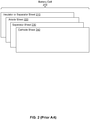
- FIG. 2 is a block diagram of conventional battery cell 200.
- Battery cell 200 includes stacked sheets 210, 220, 230, and 240, which can be wrapped into cylinders to make cylindrical cells or folded into rectangular blocks to make prismatic cells.
- Battery cell 200 can include insulator or separator sheet 210 which can be made of one or more electrically insulating materials, anode sheet 220 which can be made of one or more anode materials, separator sheet 230 which can be made of one or more separator materials, and cathode sheet 240 which can be made of one or more cathode materials.
- Example electrically insulating materials, anode materials, separator materials, and cathode materials are listed above in the context of FIG. 1 .
- insulator or separator sheet 210 can protect battery cell 200 from an environment outside the battery, anode sheet 220 can act as an anode, cathode sheet 240 can act as a cathode, and separator sheet 230 can provide some protection from a circuit being formed between anode sheet 220 and cathode sheet 240 while allowing ion flow within battery cell 200.
- insulators and separators differ, as insulators do not permit lithium ion flow, while separators do permit lithium ion flow.
- separators do permit lithium ion flow.
- insulator or separator sheet 210 was not present in battery 200, and if sheets 220, 230, and 240 were wrapped from left to right, anode sheet 220 could touch cathode sheet 240, and then battery 200 would not operate.
- insulator or separator sheet 210 is present as a separator sheet, and if sheets 210, 220, 230, and 240 were wrapped from left to right to form battery 200, the cathode and anode layers will have separators on its inner and outer sides, leading to a workable battery having a double-sided reaction. If insulator or separator sheet 210 is present as an insulator sheet, and if sheets 210, 220, 230, and 240 were wrapped from left to right to form battery 200, then each of anode sheet 220 and cathode sheet 240 has a separator layer on one side and an insulator layer on the other side, avoiding double-sided reactions.
- FIG. 3 is a diagram of battery cell 200 providing current flow 380 to an electrical load 110.
- battery cell 200 can be considered to be in a discharge mode. While in the discharge mode, lithium ions (Li+) shown as black circles in FIG. 3 , flow from anode sheet 220 through electrolyte filler 320, separator sheet 230, and electrolyte filler 330 to cathode sheet 240; that is, from left to right as shown in FIG. 3 .
- Li+ lithium ions
- Battery cell 200 can include two electrodes; a negative electrode 340 which can be a source of electron flow 370 from battery cell 200 toward electrical load 310 while battery cell 200 is in the discharge mode, and a positive electrode 350 which can be a source of current flow 380 from battery cell 200 toward electrical load 310 while battery cell 200 is in the discharge mode. Battery cell 200 can also include container 360 to provide protection from an environment outside the battery.
- Battery cell 200 can be in a discharge mode, as mentioned above, or in a charge mode.
- lithium ions of battery cell 200 move in an opposite direction from cathode sheet 240 to anode sheet 220 than shown in FIG. 3 ; that is, the lithium ions from right to left in FIG. 3 .
- current flow 380 reverses its flow direction in comparison to when battery cell 200 is in the discharge mode.
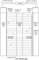
- FIG. 4 is a diagram of battery cell 200 providing current flow 380 to electrical load 310 based on a uniform lithium ion flow 410.
- a uniform lithium ion flow 410 travels from left to right in FIG. 4 from anode sheet 220, across electrolyte filler 320, separator sheet 230, and electrolyte filler 330 to arrive at cathode sheet 240.
- uniform lithium ion flow 410 is reversed; that is uniform lithium ion flow 410 travels from right to left in FIG. 4 .
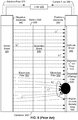
- FIG. 5 is a diagram of battery cell 200 providing current flow 380 to electrical load 310 based on distorted lithium ion flow 510.
- faults can occur that distort a uniform lithium ion flow.
- One such fault is a degradation mechanism involving lithium plating in degraded area 520. If lithium plating does occur in degraded area 520 of battery cell 200 as shown in FIG 5 , the lithium plating can result in distorted lithium ion flow 510 from anode sheet 220 to cathode sheet 240 via separator sheet 230 and electrolyte fillers 320, 330.
- Distorted lithium ion flow 510 can cause local maxima of current density, such as higher current density area 530 at the intersection of distorted lithium ion flow 510 and degraded area 520.
- FIG. 6 is a diagram of battery cell 200 having an enlarged degraded area 610. If the lithium plating mentioned in the context of FIG. 4 increases, an enlarged degraded area can occur in battery cell 200. For example, if battery cell 200 endures prolonged exposure to relatively-high heat, a result in distorted flow of lithium ions across electrodes 340, 350, separator sheet 230, and electrolyte fillers 320, 330 can expand. Then, degraded area 520 of FIG. 5 can grow to become enlarged degraded area 610 of FIG. 6 . As enlarged degraded area 610 expands, higher current density area 530 of FIG. 5 can expand to become expanded higher current density area 620 as well.
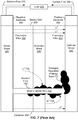
- FIG. 7 is a diagram of battery cell 200 having short channel (SC) 720 in enlarged degraded area 710. If enlarged degraded area 610 continues to grow; i.e., battery cell 200 continues to be exposed to relatively-high heat, to become enlarged degraded area 710, then enlarged degraded area 710 can eventually bridge anode sheet 220 and cathode sheet 240, resulting in short channel 720 through enlarged degraded area 710.
- SC short channel
- Short channel 720 can form a closed current loop with electron flow 730 within battery cell 200. Once short channel 720 forms and electron flow 730 begins, relatively-few electrons can flow as electron flow 370 to electrical load 310. Also, some electrons in electron flow 730 within short channel 720 can be neutralized by lithium ions 732, 734 attracted from electrolyte fillers 320, 330 to enlarged degraded area 710. The actual number of electrons in electron flow 730 to electrical load 310 can depend on the electrical resistance of short channel 720 and the electrical resistance of electrical load 310. Thus, an internal short circuit, such as short channel 720, can be difficult to detect using a sensing circuit that is external to ( i.e., outside of) battery cell 200.
- FIG. 8 is a diagram of anode sheet 220 and cathode sheet 240 of battery cell 200 providing electron flow 370 to electrical load 310 while battery cell 200 is operating in a normal discharge mode.
- electrons can be collected at negative electrode 810, which can act as a current collector, from anode sheet 220 of battery cell 200.
- the electrons can flow as electron flow 730 through electrical load 310 to positive electrode 820, which can act as a current collector.
- Electrons arriving at positive electrode 820 can be uniformly distributed across cathode sheet 240.
- lithium ion flow (not shown in FIG. 8 ) can start at anode sheet 220, continue across a separator sheet, such as separator sheet 230, and arrive at cathode sheet 240.
- FIG. 9 is diagram of anode sheet 220 and cathode sheet 240 of battery cell 200, when battery cell 200 has short channel 910.
- a discharge mode with an internal short circuit such as short channel 910
- electrons can be collected at negative electrode 810 from anode sheet 220 of battery cell 200, just as when battery cell 200 is in a normal discharge mode.
- battery cell 200 has an internal short circuit
- electrons can flow via short channel 910 to cathode sheet 240 instead of flowing to electrical load 310, leading to inhibited electron flow 920 through electrical load 310.
- the electrons arriving at cathode sheet 240 can be collected at positive electrode 820 and distributed throughout cathode sheet 240, as indicated by the arrows from short channel 910 to cathode sheet 240 and through positive electrode 820.
- electrical resistance through short channel 910 is much less than an electrical resistance through electrical load 310, and so most, if not all, electrons flow through short channel 910 rather than flow through electrical load 310, leading to inhibited electron flow 920.
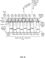
- FIG. 10 is a diagram of segmented anode sheet 1010 and negative electrode 1040 of battery cell 112c of battery 100, according to an example embodiment.
- battery cell 112c is a segmented battery cell having n battery cell segments, n > 1.
- the segments of anode sheet 1010 are shown as anode segments 1020a, 1020b, 1020c, 1020d, 1020e, 1020f, 1020g, 1020h ... 1020n.
- the anode segments are electrically insulated from each other by insulators 1024a, 1024b, 1024c, 1024d, 1024e, 1024f, 1024g, 1024h ... 1024n.
- anode segment 1020b is electrically insulated from anode segment 1020a by insulator 1024a and is electrically insulated from anode segment 1020c by insulator 1024b.
- Anode segments 1020a, 1020b, 1020c, 1020d, 1020e, 1020f, 1020g, 1020h ... 1020n are connected to anode current collector 1030, which is segmented so that each segment of anode current collector 1030 is connected to a corresponding segment of anode sheet 1010. Further, each segment of anode current collector 1030 is both electrically isolated from other anode current collector segments and connected to negative electrode 1040 via an anode current limiter (ACL). For example, FIG.
- FIG. 10 shows that: anode segment 1020a of anode sheet 1010 is connected to anode current collector segment 1032a of anode current collector 1030, anode current collector segment 1032a is also connected to anode current limiter 1022a, and anode current limiter 1022a is also connected to negative electrode 1040.
- FIG. 10 also shows that each segment of anode current collector 1030 is electrically insulated from other anode current collector segments by insulators 1024a, 1024b, 1024c, 1024d, 1024e, 1024f, 1024g, 1024h ... 1024n; e.g., anode current collector segment 1032a is separated by insulator 1024a from adjacent anode current collector segment 1032b.
- FIG. 11 is a diagram of segmented cathode sheet 1110 and positive electrode 1140 of battery cell 112c, according to an example embodiment.
- battery cell 112c has n battery cell segments, n > 1.
- the segments of cathode sheet 1110 are shown as cathode segments 1120a, 1120b, 1120c, 1120d, 1120e, 1120f, 1120g, 1120h ... 1120n.
- the cathode segments are electrically insulated from each other by insulators 1124a, 1124b, 1124c, 1124d, 1124e, 1124f, 1124g, 1124h ... 1124n.
- cathode segment 1120b is electrically insulated from cathode segment 1120a by insulator 1124a and is electrically insulated from cathode segment 1120c by insulator 1124b.
- insulators 1024a, 1024b, 1024c, 1024d, 1024e, 1024f, 1024g, 1024h, ... 1024n can be part of the same insulator as respective insulators 1124a, 1124b, 1124c, 1124d, 1124e, 1124f, 1124g, 1124h, ...
- an insulator sheet (or other configuration of an insulator) can have one end separating anode segments of anode sheet 1010 and another end separating cathode segments of cathode sheet 1110, while the insulator sheet can also separate electrolyte filler layers and separators as well, thus ensuring that no electrons, ions, and/or mass flow across the insulator.
- Cathode segments 1120a, 1120b, 1120c, 1120d, 1120e, 1120f, 1120g, 1120h ... 1120n are connected to cathode current collector 1130, which is segmented so that each segment of cathode current collector 1130 is connected to a corresponding segment of cathode sheet 1110. Further, each segment of cathode current collector 1130 is connected to positive electrode 1140 via a cathode current limiter (CCL).
- CCL cathode current limiter
- cathode segment 1120a of cathode sheet 1110 is connected to cathode current collector segment 1132a of cathode current collector 1130, cathode current collector segment 1132a is also connected to cathode current limiter 1122a, and cathode current limiter 1122a is also connected to positive electrode 1140.
- FIG. 11 also shows that each segment of cathode current collector 1130 is electrically insulated from other cathode current collector segments by insulators 1124a, 1124b, 1124c, 1124d, 1124e, 1124f, 1124g, 1124h, ... 1124n; e.g. cathode current collector segment 1132a is separated by insulator 1124a from adjacent cathode current collector segment 1132b.
- Electrons at positive electrode 1140 then flow through cathode current limiters 1122a, 1122b, 1122c, 1122d, 1122e, 1122f, 1122g, 1122h, ... 1122n to the segmented cathode current collector 1130, and then from the current collector segments to cathode segments 1120a, 1120b, 1120c, 1120d, 1120e, 1120f, 1120g, 1120h, ... 1120n of cathode sheet 1110. These electron flows are illustrated in FIG.
- a battery cell segment of battery 100 can include an anode segment of anode sheet 1010 and cathode segment of cathode sheet 1110.
- one battery cell segment of battery 100 can include: (a) anode segment 1020a, anode current collector segment 1032a, and anode current limiter 1022a that is connected to negative electrode 1040, and (b) cathode segment 1120a, cathode current collector segment 1132a, and cathode current limiter 1122a that is connected to positive electrode 1140.
- FIGS. 10 and 11 Other example battery cell segments of battery 100 can include corresponding pairs of anode and cathode segments (e.g ., anode segment 1020b paired with cathode segment 1120b), pairs of anode and cathode current collector segments (e.g., the anode current collector segment attached to anode segment 1020b paired with the cathode current collector segment attached to cathode segment 1120b, and pairs of anode and cathode current limiters (e.g ., anode current limiter 1022b paired with cathode current limiter 1122b), as shown in FIGS. 10 and 11 .
- anode current limiter 1022b paired with cathode current limiter 1122b
- battery 100 can include separators and electrolyte fillers as shown regarding battery cell segments 114m, 114n of FIG. 1 , even though FIGS. 10-13 do not show separators and electrolyte fillers regarding battery cell 112c.
- non-electrode components of battery cell 112c including, but not limited to, anode sheet 1010 and cathode sheet 1110, current collectors 1030 and 1130, current limiters 1022a, 1022b, ... 1022n and 1122a, 1122b ... 1122n, and any separators and electrolyte fillers, can be appropriately packaged and sealed into a container such as container 128; e.g., for use as a battery cell unit.
- electrodes of battery 100 such as negative electrode 1040 and positive electrode 1140, can be at least partially outside of the container to enable electrical connections with battery cell 112c.
- FIG. 12 is a diagram of segmented anode sheet 1010 and negative electrode 1040 showing an open anode current limiter 1222 for failed and isolated battery cell segment 1220 of battery cell 112c, according to an example embodiment.
- Open anode current limiter 1222 can include an open circuit that disables current from flowing through open anode current limiter 1222.
- FIG. 12 shows an example of anode sheet 1010 of battery cell 112c while operating in the discharge mode when an internal short circuit, shown as short channel 1210, occurs in battery cell segment 1220 that includes anode segment 1020h.
- short channel 1210 causes battery cell segment 1220 to fail.
- opening of open anode current limiter 1222 as a consequence of short channel 1210 causes battery cell segment 1220 to be electrically isolated.
- open anode current limiter 1222 can conditionally electrically isolate battery cell segment 1220 based on an occurrence of a short circuit within battery cell segment 1220, such the occurrence of short channel 1210 in battery cell segment 1220.
- FIG. 13 is a diagram of segmented cathode sheet 1110 and positive electrode 1140 showing an open cathode current limiter 1322 for failed and isolated battery cell segment 1220 of battery cell 112c, according to an example embodiment.
- Open cathode current limiter 1322 can include an open circuit that disables current from flowing through open cathode current limiter 1322.
- FIG. 13 shows an example of cathode sheet 1110 of battery cell 112c while operating in the discharge mode when an internal short circuit, shown as short channel 1210, occurs in battery cell segment 1220 that includes cathode segment 1120h.
- cathode current limiter 1122h If short channel 1210 occurs within battery cell segment 1220 while battery 100 is discharging, most, if not all, electrons flowing to cathode segment 1120h will flow through cathode current limiter 1122h, exceeding a maximum amount of current allowed through cathode current limiter 1122h. Exceeding the maximum amount of current allowed can cause cathode current limiter 1122h to open and become open cathode current limiter 1322. Once cathode current limiter 1122h opens to become open cathode current limiter 1322, the open cathode current limiter 1322 electrically isolates battery cell segment 1220. In the meantime, the other battery cell segments that include cathode segments 1120a, 1120b, 1120c, 1120d, 1120e, 1120f, 1120g, and 1120n can continue to operate normally.
- short channel 1210 causes battery cell segment 1220 to fail.
- opening of open anode current limiter 1322 as a consequence of short channel 1210 causes battery cell segment 1220 to be electrically isolated.
- open cathode current limiter 1322 can conditionally electrically isolate battery cell segment 1220 based on an occurrence of a short circuit within battery cell segment 1220, such the occurrence of short channel 1210 in battery cell segment 1220.
- battery 100 can recover from a short channel being formed in one (or in other cases, multiple) faulty battery cell segment(s) by opening current limiters of the faulty battery cell segment(s), such as open anode current limiter 1222 and/or open cathode current limiter 1322 of battery cell segment 1220, while any non-faulty battery cell segments can continue to operate normally.
- battery 100 likely can provide at least a limited amount of power even if a fault occurs, such as a short channel or other short circuit.
- faulty battery cell segment 1220 is electrically isolated from other battery cell segments, the likelihood that short channel 1210 will expand to other battery cell segments of battery 100 is reduced.
- FIG. 14 is a flowchart of method 1400 for storing electrical power using a battery, according to an example embodiment.
- Method 1400 can be carried out using a segmented battery such as battery 100.
- Method 1400 can begin at block 1410, where a battery can store electrical power.
- the battery can include one or more cells.
- Each cell can include a plurality of battery cell segments, where each battery cell segment can include: an anode segment, a cathode segment, and one or more current limiters, such as discussed above in the context of at least FIGS. 1 and 10-13 .
- a current limiter of the one or more current limiters can include a fuse, such as discussed above in the context of at least FIG. 1 .
- the one or more current limiters can include at least one of: a current limiter electrically connected to the anode segment and a current limiter electrically connected to the cathode segment, such as discussed above in the context of at least FIGS. 1 and 10-13 .
- each battery cell segment can further include one or more current collectors, such as discussed above in the context of at least FIGS. 1 and 10-13 .
- the one or more current collectors can include at least one of: an anode current collector electrically connected to the anode segment and a cathode current collector electrically connected to the cathode segment, such as discussed above in the context of at least FIGS. 1 and 10-13 .
- a particular current collector of the one or more current collectors can be electrically connected to an electrode, such as discussed above in the context of at least FIGS. 1 and 10-13 .
- each battery cell segment can further include a current collector of the one or more current collectors electrically connected to a current limiter of the one or more current limiters, such as discussed above in the context of at least FIGS. 1 and 10-13 .
- each battery cell segment can further include an anode current collector electrically connected to the anode sheet; and an anode current limiter electrically connected to the anode current collector, such as discussed above in the context of at least FIGS. 1 , 10 , and 12 .
- each battery cell segment can further include a cathode current collector electrically connected to the cathode sheet and a cathode current limiter electrically connected to the cathode current collector, such as discussed above in the context of at least FIGS. 1 , 11 , and 13 .
- a particular battery cell segment can be conditionally electrically isolated based on an occurrence of a short circuit within the particular battery cell segment, such as discussed above in the context of at least FIGS. 1 , 12 , and 13 .
- conditionally electrically isolating the particular battery cell segment can include conditionally electrically isolating the particular battery cell segment using a current limiter electrically connected to the anode segment of the particular battery cell segment, such as discussed above in the context of at least FIGS. 1 and 12 .
- conditionally electrically isolating the particular battery cell segment can include conditionally electrically isolating the particular battery cell segment using a current limiter electrically connected to the cathode segment of the particular battery cell segment, such as discussed above in the context of at least FIGS. 1 and 13 .
- method 1400 can further electrically isolating the particular battery cell segment from one or more other battery cell segments of the plurality of battery cell segments using one or more insulator sheets, such as discussed above in the context of at least FIGS. 1 , 12 , and 13 .
- method 1400 can further include: electrically connecting at least two battery cell segments of the plurality of battery cell segments using one or more electrodes, such as discussed above in the context of at least FIGS. 1 and 10-13 .
- a particular battery cell segment of the at least two battery cell segments can include at least one of: an anode current collector electrically connected to the anode segment and to a negative electrode of the one or more electrodes; and a cathode current collector electrically connected to the cathode segment and to a positive electrode of the one or more electrodes, such as discussed above in the context of at least FIGS. 1 and 10-13 .
- the anode current collector can be electrically connected to the negative electrode via an anode current limiter of the one or more current limiters; and the cathode current collector can be electrically connected to the positive electrode via a cathode current limiter of the one or more current limiters, such as discussed above in the context of at least FIGS. 1 and 10-13 .
- FIG. 15 is a flowchart of method 1500 for providing electrical power using a battery, according to an example embodiment.
- Method 1500 can be carried out using a segmented battery such as battery 100.
- Method 1500 can begin at block 1510, where a battery can provide electrical power to a load.
- the battery can include one or more cells.
- Each cell can include a plurality of battery cell segments, where each battery cell segment can include: an anode segment, a cathode segment, and one or more current limiters, such as discussed above in the context of at least FIGS. 1 and 10-13 .
- a current limiter of the one or more current limiters can include a fuse, such as discussed above in the context of at least FIG. 1 .
- the one or more current limiters can include at least one of: a current limiter electrically connected to the anode segment and a current limiter electrically connected to the cathode segment, such as discussed above in the context of at least FIGS. 1 and 10-13 .
- each battery cell segment can further include one or more current collectors, such as discussed above in the context of at least FIGS. 1 and 10-13 .
- the one or more current collectors can include at least one of: an anode current collector electrically connected to the anode segment and a cathode current collector electrically connected to the cathode segment, such as discussed above in the context of at least FIGS. 1 and 10-13 .
- a particular current collector of the one or more current collectors can be electrically connected to an electrode, such as discussed above in the context of at least FIGS. 1 and 10-13 .
- the particular current collector can be electrically connected to the electrode using a particular current limiter of the one or more current limiters, such as discussed above in the context of at least FIGS. 1 and 10-13 .
- each battery cell segment can further include a current collector of the one or more current collectors electrically connected to a current limiter of the one or more current limiters, such as discussed above in the context of at least FIGS. 1 and 10-13 .
- each battery cell segment can further include an anode current collector electrically connected to the anode sheet; and an anode current limiter electrically connected to the anode current collector, such as discussed above in the context of at least FIGS. 1 , 10 , and 12 .
- Each battery cell segment can further include a cathode current collector electrically connected to the cathode sheet and a cathode current limiter electrically connected to the cathode current collector, such as discussed above in the context of at least FIGS. 1 , 11 , and 13 .
- a particular battery cell segment can be conditionally electrically isolated based on an occurrence of a short circuit within the particular battery cell segment, such as discussed above in the context of at least FIGS. 1 , 12 , and 13 .
- conditionally electrically isolating the particular battery cell segment can include conditionally electrically isolating the particular battery cell segment using one of: a current limiter electrically connected to the anode segment of the particular battery cell segment, and a current limiter electrically connected to the cathode segment of the particular battery cell segment, such as discussed above in the context of at least FIGS. 1 , 12 , and 13 .
- each block in the disclosed flowcharts may represent circuitry that is wired to perform the specific logical functions in the process.
- Alternative implementations are included within the scope of the example embodiments of the present disclosure in which functions may be executed out of order from that shown or discussed, including substantially concurrent or in reverse order, depending on the functionality involved, as would be understood by those reasonably skilled in the art.
Landscapes
- Chemical & Material Sciences (AREA)
- Chemical Kinetics & Catalysis (AREA)
- Electrochemistry (AREA)
- General Chemical & Material Sciences (AREA)
- Engineering & Computer Science (AREA)
- Manufacturing & Machinery (AREA)
- Microelectronics & Electronic Packaging (AREA)
- Materials Engineering (AREA)
- Connection Of Batteries Or Terminals (AREA)
- Secondary Cells (AREA)
Abstract
Description
- The present disclosure generally relates to electrical batteries, and more particularly to methods and apparatus related to batteries that have a plurality of battery cell segments.
- Batteries are used to store and provide electrical power for aircraft, ground vehicles, personal electronic devices, and other electrically-powered devices. A battery can have a positive terminal or electrode and a negative terminal or electrode. Then, a "load" or device that draws power from the battery, can be connected via electrical conductors, such as wires, electrical contacts, and/or cables, to the positive terminal and the negative terminal in an electrical circuit. The battery can then operate in a discharge mode while providing power to the load. To charge the battery, a source of electrical power can be electrically connected to the positive terminal and the negative terminal in an electrical circuit, and the battery can operate in a charge mode to "charge" or draw and store power from the source. In some applications, as batteries used in vehicular and electrical power systems, the battery can be connected to one or more devices that can act as both a load and a source of electrical power to the rest of the car. While the car is being started, the rest of the car can act as a load to draw power from the car battery. After the car has started, an alternator and/or regenerative braking system of the car can act as a source of electrical power to charge the battery.
- In some cases, batteries can fail due to environmental conditions, faults in the construction and/or design of the battery, physical damage to the battery, and the (gradual) deterioration of chemicals by the battery to store and provide current. These faults can lead to electrical open circuits, where no power is provided to the circuit, and/or battery internal electrical short circuits, where a path of low electrical resistance within the battery is created. A short circuit can lead to an unexpectedly large amount of power being provided to a component of an electrical circuit, including but not limited to, a battery in the electrical circuit.
- In an example embodiment, a battery is described. The battery includes one or more cells. Each cell includes a plurality of battery cell segments. Each battery cell segment includes: an anode segment, a cathode segment, and one or more current limiters configured to conditionally electrically isolate the battery cell segment based on an occurrence of a short circuit within the battery cell segment.
- In another example embodiment, a method is described. Electrical power is stored using a battery, where the battery includes one or more cells, where each cell includes a plurality of battery cell segments, and where each battery cell segment includes: an anode segment, a cathode segment, and one or more current limiters. A particular battery cell segment is conditionally electrically isolated based on an occurrence of a short circuit within the battery cell segment.
- In a further example embodiment, a method is described. Electrical power is provided to a load using a battery, where the battery includes one or more cells, where each cell includes a plurality of battery cell segments, and where each battery cell segment includes: an anode segment, a cathode segment, and one or more current limiters. A particular battery cell segment is conditionally electrically isolated based on an occurrence of a short circuit within the battery cell segment.
- It should be understood that the description provided in this summary section and elsewhere in this document is intended to illustrate aspects of the present disclosure by way of non-limiting example. Generally, the features, functions, components, and advantages that are discussed herein can be achieved independently in various embodiments or may be combined in yet other embodiments, further details of which are disclosed in the following description and the accompanying drawings.
-
-
FIG. 1 is a block diagram of a battery and an electrical load, according to an example embodiment. -
FIG. 2 is a block diagram of a conventional battery cell. -
FIG. 3 is a diagram of the battery cell ofFIG. 2 providing current to an electrical load. -
FIG. 4 is a diagram of the battery cell ofFIG. 2 providing current to the electrical load based on a uniform ion flow. -
FIG. 5 is a diagram of the battery cell ofFIG. 2 providing current to the electrical load based on a degraded ion flow. -
FIG. 6 is a diagram of the battery cell ofFIG. 2 having an enlarged degraded area. -
FIG. 7 is a diagram of the battery cell ofFIG. 2 having a short channel in an enlarged degraded area. -
FIG. 8 is a diagram of anode and cathode sheets of the battery cell ofFIG. 2 providing an electron flow to the electrical load while operating in a normal discharge mode. -
FIG. 9 is a diagram of the anode and cathode sheets of the battery cell ofFIG. 2 having a short channel. -
FIG. 10 is a diagram of a segmented anode sheet and a negative electrode of a battery cell of the battery ofFIG. 1 , according to an example embodiment. -
FIG. 11 is a diagram of a segmented cathode sheet and a positive electrode of the battery cell ofFIG. 10 , according to an example embodiment. -
FIG. 12 is a diagram of the segmented anode sheet and the negative electrode showing an open-circuited current limiter for a failed and isolated segment of the battery cell ofFIGS. 10 and11 , according to an example embodiment. -
FIG. 13 is a diagram of the segmented cathode sheet and the positive electrode showing an open-circuited current limiter for a failed and isolated segment of the battery cell ofFIGS. 10 and11 , according to an example embodiment. -
FIG. 14 is a flowchart of a method for storing electrical power using a battery, according to an example embodiment. -
FIG. 15 is a flowchart of a method for providing electrical power using a battery, according to an example embodiment. - An internal short circuit may occur in a lithium ion battery cell. Such internal short circuits are difficult, if not impossible, to sense and managed externally and can cause damage to the entire battery. In some cases, internal short circuits can lead to battery fires, and the attendant risk to an environment proximate to the battery. In some examples, battery chemistry can be changed to reduce electrical activity of the battery and so reduce the risk of an internal short. The drawback of this approach is that it reduces the battery energy density, making batteries relatively larger.
- To reduce these risks, a battery with one or more cells, each cell including a plurality of battery cell segments is described. Each battery cell segment is electrically isolated, and so the use of these battery cell segments provides a battery that can prevent and isolate a potential internal short circuit, thus keeping the battery safe and operational. Each battery cell segment is internal to the battery and/or a cell of the battery, and so no internal sensing is required. Rather, each battery cell segment has one or more current limiters that can detect a short circuit within the battery cell segment and consequently break an electrical circuit. Thus, a battery using battery circuits with current limiters enables automatic detection, location, and isolation of (potential) short circuits within the battery cell segment, keeping the remaining segments of the battery safe and operational.
- More particularly, a battery cell segment of a battery can have an anode segment, a cathode segment, and one or more current limiters configured to conditionally electrically isolate the battery cell segment based on an occurrence of a short circuit within the battery cell segment. A current limiter of the one or more current limiters can be, or include, one or more electrical components that restrict current flow to a maximum amount. The current limiters can include a current limiter electrically connected to the anode segment and/or a current limiter electrically connected to the cathode segment.
- A battery cell segment can include one or more insulators that electrically isolate the battery cell segment from one or more other battery cell segments and/or one or more current collectors. For example, an insulator of a battery cell segment can be shaped as an insulator strip whose thickness is based on the thickness of other layers of the battery; e.g., as thick as the total thickness of anode, cathode, separator, and electrolyte layers. A current collector can receive electrons from either the battery or from a circuit connected to the battery. For example, a battery cell segment can have an anode current collector electrically connected to the anode segment; and/or a cathode current collector electrically connected to the cathode segment.
- Current collectors of a battery cell segment can be electrically connected to battery electrodes. For example, the anode current collector can also be electrically connected to a negative electrode for the battery, and/or the cathode current collector can also be electrically connected to a positive electrode for the battery. The battery electrodes can electrically connect multiple segments and/or cells of the battery.
- A current limiter of a battery cell segment can electrically connect a current collector of a segment and a battery electrode; then, the current limiter can restrict an amount of current being provided from the battery cell segment (via the current collector) to the electrode or vice versa. In particular, a battery cell segment can have an anode current collector electrically connected to the anode sheet and an anode current limiter electrically connecting the anode current collector to a negative battery electrode and/or a cathode current collector electrically connected to the cathode sheet and a cathode current limiter electrically connecting the cathode current collector to a positive battery electrode Examples of segmented batteries include, but are not limited to, lithium ion batteries. Lithium ion batteries can have lithium in one or more anodes for releasing electrons; i.e., anode sheets and/or anode segments. The electrons released by the anode(s) can be received at cathode(s); i.e., cathode sheets and/or cathode segments, of these lithium ion batteries. In some cases, an electrolyte can be used as filler and aid transfer of ions between electrodes of the battery.
- Battery cell segments can be used with a wide variety of battery chemistries, including but not limited to lithium-ion based battery chemistries. Examples of other battery chemistries, such as other high energy density batteries, can use other materials for anodes and/or cathodes than used in lithium ion batteries. Batteries using these other battery chemistries can be segmented using the same or similar techniques disclosed herein for segmenting batteries. Batteries of virtually any size can utilize battery cell segments, from relatively-small batteries, such as used in personal electronics and other applications, to relatively-large batteries used in vehicles, including aircraft, sea craft, and land vehicle and other applications. Thus, the use of segmented batteries can improve battery safety for a wide range of batteries and battery applications.
-
FIG. 1 is a block diagram ofbattery 100 andelectrical load 110, according to an example embodiment. A top portion ofFIG. 1 illustrates thatbattery 100 andelectrical load 110 are connected viawires Battery 100 can store electrical power and provide some or all of the stored power toelectrical load 110 aselectrical power 106 whilebattery 100 is operating in a discharge mode, as indicated by an arrow ofelectrical power 106 going frombattery 100 toelectrical load 110. In some examples,electrical load 110 can be replaced by and/or include a power source providing power tobattery 100 operating in a charge mode, as indicated by an arrow ofelectrical power 106 going fromelectrical load 110 tobattery 100. -
Battery 100 can include c cells, c > 0, that includecells 112a', 112a, 112b', 112b ... 112c', 112c which can be connected in series and/or parallel. At least one ofcells 112a', 112a, 112b', 112b ... 112c', 112c, can include two or more battery cell segments (BCSs). For example, a upper-central portion ofFIG. 1 showscell 112c is made up of n battery cell segments, n > 1, which includebattery cell segments battery 100 can include a plurality of battery cell segments; e.g.,battery cell segments cell 112c and battery cell segments incells 112a', 112a, 112b', 112b, ... (not shown inFIG. 1 ). -
Battery cell segments cell 112c. In particular, battery cell segments and/or cells ofbattery 100 can be electrically connected in parallel to electrodes, such asnegative electrode 120 andpositive electrode 150.Electrodes electrical load 110 tobattery 100 operating in the charge mode or conduct electrical current / electrical power toelectrical load 110 frombattery 100 operating in the discharge mode. Power can be provided to and/or drawn frombattery 100 as part of a circuit that electrically connectsnegative electrode 120 andpositive electrode 150; e.g., acircuit including battery 100,wire 102 connectingbattery 100 withelectrical load 110, andwire 104 also connectingbattery 100 withelectrical load 110. - A lower portion of
FIG. 1 shows a top view of neighboringbattery cell segments Battery cell segments cell 112c are both electrically connected tonegative electrode 120 andpositive electrode 150.Insulator 126 separatesbattery cell segments segments anode segments electrolyte fillers 134m, 134n, separator sheet segments (SSSs) 136m, 136n,electrolyte fillers cathode segments current collector segments current limiters battery cell segment 114m can include only anodecurrent limiter 122m (or only cathodecurrent limiter 144m) rather than bothcurrent limiters -
Negative electrode 120 is electrically connected to respectivebattery cell segments current limiters 122m, 122n, which are also electrically connected to respective anodecurrent collector segments current limiters - A current limiter can conditionally isolate a battery cell segment when a fault condition, such as an internal short circuit, occurs that involves the battery cell segment. For example, if an internal short circuit occurs within
battery cell segment 114m, then a relatively-large amount of current can flow throughbattery cell segment 114m. In this condition where an internal short circuit occurs, anodecurrent limiter 122m and/or cathodecurrent limiter 144m can conditionally electrically isolatebattery cell segment 114m. Other examples of conditionally isolating battery cell segments using current limiters are possible as well. -
Current collector segments battery 100 and provide the electrons to acircuit connecting battery 100 toelectrical load 110, or vice versa. In some examples, some or all ofcurrent collector segments - Anode
current collector segments current collector 130 and of respectivebattery cell segments respective anode segments Respective anode segments electrolytic filler 134m, 134n,separator sheet segments 136m, 136n, andelectrolytic filler respective cathode segments Electrolyte fillers Respective cathode segments current collector segments current collector segments current limiters battery cell segments positive electrode 150. - An insulator of
battery 100 can chemically insulate and/or electrically insulate, or resist current flow, between components ofbattery 100. As examples,insulators 124 and 126 electrically insulatebattery cell segment 114m from adjacent battery cell segments; e.g.,insulator sheet 126 electrically insulatesbattery cell segment 114m frombattery cell segment 114n. Other components ofbattery 100 can act as insulators; e.g.,container 128 can electrically insulate and otherwise protectbattery cell segment 114n from an environment outsidebattery 100. -
Separator sheet segments 136m, 136n can be made of one or more separator materials and provide some protection from a circuit being formed between an anode segment and a cathode segment of a battery cell segment while allowing ion flow withinbattery 100. However, if either ofseparator sheet segments 136m, 136n fails to prevent formation of a short circuit between arespective anode segment respective cathode segment current limiters 122m, 122n and/or respective cathodecurrent limiters battery cell segments - In some examples,
battery 100 can be a lithium ion battery. In these lithium-ion examples, anodes, such asanode segments cathode segments - Insulators of
battery 100, such asinsulators 124, 126, can be made up of one or more electrically insulating materials, including but not limited to, polyvinyl chloride, polyethylene terephthalate, polypropylene, tetrafluoroethylene, polyolefin, ceramics, cotton, nylon, polyester, glass, wood, and wood products, such as cardboard or paper. Other insulator sheets and/or materials are possible as well. Separators ofbattery 100, such asseparator sheet segments 136m, 136n, can be made of separator materials, where separator materials can be the same materials as the above-mentioned electrically insulating materials. - In designing
battery 100, a minimum number of battery cell segments per cell can be determined. Consider that the maximum allowed current of a segment is Imax for a duration of time τ, beyond which the segment may be subject to an accelerated thermal degradation or damage, where values of Imax and τ for a specific battery can be determined experimentally according to the specific battery's chemistry. Then, if a cell capacity is C, a minimum number n of battery cell segments of a cell can be determined using the following equation:
-
FIG. 2 is a block diagram ofconventional battery cell 200.Battery cell 200 includes stackedsheets Battery cell 200 can include insulator or separator sheet 210 which can be made of one or more electrically insulating materials,anode sheet 220 which can be made of one or more anode materials,separator sheet 230 which can be made of one or more separator materials, andcathode sheet 240 which can be made of one or more cathode materials. Example electrically insulating materials, anode materials, separator materials, and cathode materials are listed above in the context ofFIG. 1 . Inbattery cell 200, insulator or separator sheet 210 can protectbattery cell 200 from an environment outside the battery,anode sheet 220 can act as an anode,cathode sheet 240 can act as a cathode, andseparator sheet 230 can provide some protection from a circuit being formed betweenanode sheet 220 andcathode sheet 240 while allowing ion flow withinbattery cell 200. - In
batteries example battery 200, if insulator or separator sheet 210 was not present inbattery 200, and ifsheets anode sheet 220 could touchcathode sheet 240, and thenbattery 200 would not operate. If insulator or separator sheet 210 is present as a separator sheet, and ifsheets battery 200, the cathode and anode layers will have separators on its inner and outer sides, leading to a workable battery having a double-sided reaction. If insulator or separator sheet 210 is present as an insulator sheet, and ifsheets battery 200, then each ofanode sheet 220 andcathode sheet 240 has a separator layer on one side and an insulator layer on the other side, avoiding double-sided reactions. -
FIG. 3 is a diagram ofbattery cell 200 providingcurrent flow 380 to anelectrical load 110. Asbattery cell 200 is providing current (as current flow 380) toelectrical load 310,battery cell 200 can be considered to be in a discharge mode. While in the discharge mode, lithium ions (Li+) shown as black circles inFIG. 3 , flow fromanode sheet 220 throughelectrolyte filler 320,separator sheet 230, andelectrolyte filler 330 tocathode sheet 240; that is, from left to right as shown inFIG. 3 . -
Battery cell 200 can include two electrodes; anegative electrode 340 which can be a source ofelectron flow 370 frombattery cell 200 towardelectrical load 310 whilebattery cell 200 is in the discharge mode, and apositive electrode 350 which can be a source ofcurrent flow 380 frombattery cell 200 towardelectrical load 310 whilebattery cell 200 is in the discharge mode.Battery cell 200 can also includecontainer 360 to provide protection from an environment outside the battery. -
Battery cell 200 can be in a discharge mode, as mentioned above, or in a charge mode. Whenbattery cell 200 is in the charge mode, lithium ions ofbattery cell 200 move in an opposite direction fromcathode sheet 240 toanode sheet 220 than shown inFIG. 3 ; that is, the lithium ions from right to left inFIG. 3 . Whenbattery cell 200 is in the charge mode,current flow 380 reverses its flow direction in comparison to whenbattery cell 200 is in the discharge mode. -
FIG. 4 is a diagram ofbattery cell 200 providingcurrent flow 380 toelectrical load 310 based on a uniformlithium ion flow 410. In a normal condition ofbattery cell 200 operating in the discharge mode, a uniformlithium ion flow 410 travels from left to right inFIG. 4 fromanode sheet 220, acrosselectrolyte filler 320,separator sheet 230, andelectrolyte filler 330 to arrive atcathode sheet 240. In a normal condition ofbattery cell 200 operating in the charge mode, uniformlithium ion flow 410 is reversed; that is uniformlithium ion flow 410 travels from right to left inFIG. 4 . -
FIG. 5 is a diagram ofbattery cell 200 providingcurrent flow 380 toelectrical load 310 based on distortedlithium ion flow 510. Whenbattery cell 200 is operating in a discharge mode, faults can occur that distort a uniform lithium ion flow. One such fault is a degradation mechanism involving lithium plating indegraded area 520. If lithium plating does occur indegraded area 520 ofbattery cell 200 as shown inFIG 5 , the lithium plating can result in distortedlithium ion flow 510 fromanode sheet 220 tocathode sheet 240 viaseparator sheet 230 andelectrolyte fillers lithium ion flow 510 can cause local maxima of current density, such as highercurrent density area 530 at the intersection of distortedlithium ion flow 510 anddegraded area 520. -
FIG. 6 is a diagram ofbattery cell 200 having an enlargeddegraded area 610. If the lithium plating mentioned in the context ofFIG. 4 increases, an enlarged degraded area can occur inbattery cell 200. For example, ifbattery cell 200 endures prolonged exposure to relatively-high heat, a result in distorted flow of lithium ions acrosselectrodes separator sheet 230, andelectrolyte fillers degraded area 520 ofFIG. 5 can grow to become enlargeddegraded area 610 ofFIG. 6 . As enlargeddegraded area 610 expands, highercurrent density area 530 ofFIG. 5 can expand to become expanded higher current density area 620 as well. -
FIG. 7 is a diagram ofbattery cell 200 having short channel (SC) 720 in enlargeddegraded area 710. If enlargeddegraded area 610 continues to grow; i.e.,battery cell 200 continues to be exposed to relatively-high heat, to become enlargeddegraded area 710, then enlarged degradedarea 710 can eventually bridgeanode sheet 220 andcathode sheet 240, resulting inshort channel 720 through enlargeddegraded area 710. -
Short channel 720 can form a closed current loop withelectron flow 730 withinbattery cell 200. Onceshort channel 720 forms andelectron flow 730 begins, relatively-few electrons can flow aselectron flow 370 toelectrical load 310. Also, some electrons inelectron flow 730 withinshort channel 720 can be neutralized bylithium ions electrolyte fillers degraded area 710. The actual number of electrons inelectron flow 730 toelectrical load 310 can depend on the electrical resistance ofshort channel 720 and the electrical resistance ofelectrical load 310. Thus, an internal short circuit, such asshort channel 720, can be difficult to detect using a sensing circuit that is external to (i.e., outside of)battery cell 200. -
FIG. 8 is a diagram ofanode sheet 220 andcathode sheet 240 ofbattery cell 200 providingelectron flow 370 toelectrical load 310 whilebattery cell 200 is operating in a normal discharge mode. In the normal discharge mode, electrons can be collected atnegative electrode 810, which can act as a current collector, fromanode sheet 220 ofbattery cell 200. The electrons can flow aselectron flow 730 throughelectrical load 310 topositive electrode 820, which can act as a current collector. Electrons arriving atpositive electrode 820 can be uniformly distributed acrosscathode sheet 240. In the discharge mode, lithium ion flow (not shown inFIG. 8 ) can start atanode sheet 220, continue across a separator sheet, such asseparator sheet 230, and arrive atcathode sheet 240. -
FIG. 9 is diagram ofanode sheet 220 andcathode sheet 240 ofbattery cell 200, whenbattery cell 200 hasshort channel 910. In a discharge mode with an internal short circuit such asshort channel 910, electrons can be collected atnegative electrode 810 fromanode sheet 220 ofbattery cell 200, just as whenbattery cell 200 is in a normal discharge mode. However, whenbattery cell 200 has an internal short circuit, electrons can flow viashort channel 910 tocathode sheet 240 instead of flowing toelectrical load 310, leading toinhibited electron flow 920 throughelectrical load 310. The electrons arriving atcathode sheet 240 can be collected atpositive electrode 820 and distributed throughoutcathode sheet 240, as indicated by the arrows fromshort channel 910 tocathode sheet 240 and throughpositive electrode 820. Typically, electrical resistance throughshort channel 910 is much less than an electrical resistance throughelectrical load 310, and so most, if not all, electrons flow throughshort channel 910 rather than flow throughelectrical load 310, leading toinhibited electron flow 920. -
FIG. 10 is a diagram ofsegmented anode sheet 1010 andnegative electrode 1040 ofbattery cell 112c ofbattery 100, according to an example embodiment. As indicated inFIGS. 1 and10-13 ,battery cell 112c is a segmented battery cell having n battery cell segments, n > 1. InFIG. 10 , the segments ofanode sheet 1010 are shown asanode segments insulators anode segment 1020b is electrically insulated fromanode segment 1020a byinsulator 1024a and is electrically insulated fromanode segment 1020c byinsulator 1024b. -
Anode segments current collector 1030, which is segmented so that each segment of anodecurrent collector 1030 is connected to a corresponding segment ofanode sheet 1010. Further, each segment of anodecurrent collector 1030 is both electrically isolated from other anode current collector segments and connected tonegative electrode 1040 via an anode current limiter (ACL). For example,FIG. 10 shows that:anode segment 1020a ofanode sheet 1010 is connected to anodecurrent collector segment 1032a of anodecurrent collector 1030, anodecurrent collector segment 1032a is also connected to anodecurrent limiter 1022a, and anodecurrent limiter 1022a is also connected tonegative electrode 1040.FIG. 10 also shows that each segment of anodecurrent collector 1030 is electrically insulated from other anode current collector segments byinsulators current collector segment 1032a is separated byinsulator 1024a from adjacent anodecurrent collector segment 1032b. - When
battery 100 is in a normal discharge mode, electrons are collected at segmented anodecurrent collector 1030 fromanode segments anode sheet 1010. The collected electrons flow from segmented anodecurrent collector 1030 through anodecurrent limiters negative electrode 1040. These electron flows are illustrated inFIG. 10 by arrows fromanode sheet 1010 to anodecurrent collector 1030, arrows from anodecurrent collector 1030 through anodecurrent limiters 1022a ... 1022n tonegative electrode 1040. The electrons then flow fromnegative electrode 1040 toelectrical load 110 and then aselectron flow 1050 to a cathode sheet, which is shown inFIG. 11 . -
FIG. 11 is a diagram ofsegmented cathode sheet 1110 andpositive electrode 1140 ofbattery cell 112c, according to an example embodiment. As indicated inFIGS. 1 and10-13 ,battery cell 112c has n battery cell segments, n > 1. InFIG. 11 , the segments ofcathode sheet 1110 are shown ascathode segments insulators cathode segment 1120b is electrically insulated fromcathode segment 1120a byinsulator 1124a and is electrically insulated fromcathode segment 1120c byinsulator 1124b. In some examples,insulators respective insulators anode sheet 1010 and another end separating cathode segments ofcathode sheet 1110, while the insulator sheet can also separate electrolyte filler layers and separators as well, thus ensuring that no electrons, ions, and/or mass flow across the insulator. -
Cathode segments cathode current collector 1130, which is segmented so that each segment of cathodecurrent collector 1130 is connected to a corresponding segment ofcathode sheet 1110. Further, each segment of cathodecurrent collector 1130 is connected topositive electrode 1140 via a cathode current limiter (CCL). For example,FIG. 11 shows that:cathode segment 1120a ofcathode sheet 1110 is connected to cathode current collector segment 1132a of cathodecurrent collector 1130, cathode current collector segment 1132a is also connected to cathodecurrent limiter 1122a, and cathodecurrent limiter 1122a is also connected topositive electrode 1140.FIG. 11 also shows that each segment of cathodecurrent collector 1130 is electrically insulated from other cathode current collector segments byinsulators insulator 1124a from adjacent cathodecurrent collector segment 1132b. - When
battery 100 is in a normal discharge mode, electrons flow fromanode sheet 1010 aselectron flow 1150 topositive electrode 1140. Electrons atpositive electrode 1140 then flow through cathodecurrent limiters cathode current collector 1130, and then from the current collector segments tocathode segments cathode sheet 1110. These electron flows are illustrated inFIG. 11 by arrows fromelectron flow 1150 fromelectrical load 110 topositive electrode 1140, through to cathodecurrent limiters 1122a ... 1122n, continuing tocathode current collector 1130, and then tocathode segments 1120a ... 1120n ofcathode sheet 1110. - A battery cell segment of
battery 100, such as a segment ofbattery cell 112c, can include an anode segment ofanode sheet 1010 and cathode segment ofcathode sheet 1110. For example, one battery cell segment ofbattery 100 can include: (a)anode segment 1020a, anodecurrent collector segment 1032a, and anodecurrent limiter 1022a that is connected tonegative electrode 1040, and (b)cathode segment 1120a, cathode current collector segment 1132a, and cathodecurrent limiter 1122a that is connected topositive electrode 1140. Other example battery cell segments ofbattery 100 can include corresponding pairs of anode and cathode segments (e.g.,anode segment 1020b paired withcathode segment 1120b), pairs of anode and cathode current collector segments (e.g., the anode current collector segment attached toanode segment 1020b paired with the cathode current collector segment attached tocathode segment 1120b, and pairs of anode and cathode current limiters (e.g., anodecurrent limiter 1022b paired with cathodecurrent limiter 1122b), as shown inFIGS. 10 and11 . - Note that
battery 100 can include separators and electrolyte fillers as shown regardingbattery cell segments FIG. 1 , even thoughFIGS. 10-13 do not show separators and electrolyte fillers regardingbattery cell 112c. Additionally, non-electrode components ofbattery cell 112c including, but not limited to,anode sheet 1010 andcathode sheet 1110,current collectors current limiters container 128; e.g., for use as a battery cell unit. Then electrodes ofbattery 100, such asnegative electrode 1040 andpositive electrode 1140, can be at least partially outside of the container to enable electrical connections withbattery cell 112c. -
FIG. 12 is a diagram ofsegmented anode sheet 1010 andnegative electrode 1040 showing an open anodecurrent limiter 1222 for failed and isolatedbattery cell segment 1220 ofbattery cell 112c, according to an example embodiment. Open anodecurrent limiter 1222 can include an open circuit that disables current from flowing through open anodecurrent limiter 1222.FIG. 12 shows an example ofanode sheet 1010 ofbattery cell 112c while operating in the discharge mode when an internal short circuit, shown asshort channel 1210, occurs inbattery cell segment 1220 that includesanode segment 1020h. Ifshort channel 1210 occurs withinbattery cell segment 1220 whilebattery 100 is discharging, most, if not all, electrons flowing fromanode segment 1020h will flow through anodecurrent limiter 1022h, exceeding a maximum amount of current allowed through anodecurrent limiter 1022h. Exceeding the maximum amount of current allowed can cause anodecurrent limiter 1022h to open (i.e., have an open circuit) and become open anodecurrent limiter 1222. Once anodecurrent limiter 1022h opens to become open anodecurrent limiter 1222, the open anodecurrent limiter 1222 electrically isolatesbattery cell segment 1220. In the meantime, the other battery cell segments that includeanode segments - Thus, the presence of
short channel 1210 causesbattery cell segment 1220 to fail. Further, the opening of open anodecurrent limiter 1222 as a consequence ofshort channel 1210 causesbattery cell segment 1220 to be electrically isolated. As such, open anodecurrent limiter 1222 can conditionally electrically isolatebattery cell segment 1220 based on an occurrence of a short circuit withinbattery cell segment 1220, such the occurrence ofshort channel 1210 inbattery cell segment 1220. -
FIG. 13 is a diagram ofsegmented cathode sheet 1110 andpositive electrode 1140 showing an open cathodecurrent limiter 1322 for failed and isolatedbattery cell segment 1220 ofbattery cell 112c, according to an example embodiment. Open cathodecurrent limiter 1322 can include an open circuit that disables current from flowing through open cathodecurrent limiter 1322.FIG. 13 shows an example ofcathode sheet 1110 ofbattery cell 112c while operating in the discharge mode when an internal short circuit, shown asshort channel 1210, occurs inbattery cell segment 1220 that includescathode segment 1120h. Ifshort channel 1210 occurs withinbattery cell segment 1220 whilebattery 100 is discharging, most, if not all, electrons flowing tocathode segment 1120h will flow through cathodecurrent limiter 1122h, exceeding a maximum amount of current allowed through cathodecurrent limiter 1122h. Exceeding the maximum amount of current allowed can cause cathodecurrent limiter 1122h to open and become open cathodecurrent limiter 1322. Once cathodecurrent limiter 1122h opens to become open cathodecurrent limiter 1322, the open cathodecurrent limiter 1322 electrically isolatesbattery cell segment 1220. In the meantime, the other battery cell segments that includecathode segments - Thus, the presence of
short channel 1210 causesbattery cell segment 1220 to fail. Further, the opening of open anodecurrent limiter 1322 as a consequence ofshort channel 1210 causesbattery cell segment 1220 to be electrically isolated. As such, open cathodecurrent limiter 1322 can conditionally electrically isolatebattery cell segment 1220 based on an occurrence of a short circuit withinbattery cell segment 1220, such the occurrence ofshort channel 1210 inbattery cell segment 1220. - Further,
battery 100 can recover from a short channel being formed in one (or in other cases, multiple) faulty battery cell segment(s) by opening current limiters of the faulty battery cell segment(s), such as open anodecurrent limiter 1222 and/or open cathodecurrent limiter 1322 ofbattery cell segment 1220, while any non-faulty battery cell segments can continue to operate normally. As such,battery 100 likely can provide at least a limited amount of power even if a fault occurs, such as a short channel or other short circuit. Additionally, as faultybattery cell segment 1220 is electrically isolated from other battery cell segments, the likelihood thatshort channel 1210 will expand to other battery cell segments ofbattery 100 is reduced. -
FIG. 14 is a flowchart of method 1400 for storing electrical power using a battery, according to an example embodiment. Method 1400 can be carried out using a segmented battery such asbattery 100. Method 1400 can begin at block 1410, where a battery can store electrical power. The battery can include one or more cells. Each cell can include a plurality of battery cell segments, where each battery cell segment can include: an anode segment, a cathode segment, and one or more current limiters, such as discussed above in the context of at leastFIGS. 1 and10-13 . - In some embodiments, a current limiter of the one or more current limiters can include a fuse, such as discussed above in the context of at least
FIG. 1 . In other embodiments, the one or more current limiters can include at least one of: a current limiter electrically connected to the anode segment and a current limiter electrically connected to the cathode segment, such as discussed above in the context of at leastFIGS. 1 and10-13 . - In still other embodiments, each battery cell segment can further include one or more current collectors, such as discussed above in the context of at least
FIGS. 1 and10-13 . In some of these embodiments, the one or more current collectors can include at least one of: an anode current collector electrically connected to the anode segment and a cathode current collector electrically connected to the cathode segment, such as discussed above in the context of at leastFIGS. 1 and10-13 . In still other of these embodiments, a particular current collector of the one or more current collectors can be electrically connected to an electrode, such as discussed above in the context of at leastFIGS. 1 and10-13 . In particular, the particular current collector can be electrically connected to the electrode using a particular current limiter of the one or more current limiters, such as discussed above in the context of at leastFIGS. 1 and10-13 . In further embodiments, each battery cell segment can further include a current collector of the one or more current collectors electrically connected to a current limiter of the one or more current limiters, such as discussed above in the context of at leastFIGS. 1 and10-13 . In particular, each battery cell segment can further include an anode current collector electrically connected to the anode sheet; and an anode current limiter electrically connected to the anode current collector, such as discussed above in the context of at leastFIGS. 1 ,10 , and12 . In still further embodiments, each battery cell segment can further include a cathode current collector electrically connected to the cathode sheet and a cathode current limiter electrically connected to the cathode current collector, such as discussed above in the context of at leastFIGS. 1 ,11 , and13 . - At
block 1420, a particular battery cell segment can be conditionally electrically isolated based on an occurrence of a short circuit within the particular battery cell segment, such as discussed above in the context of at leastFIGS. 1 ,12 , and13 . - In some embodiments, conditionally electrically isolating the particular battery cell segment can include conditionally electrically isolating the particular battery cell segment using a current limiter electrically connected to the anode segment of the particular battery cell segment, such as discussed above in the context of at least
FIGS. 1 and12 . - In other embodiments, conditionally electrically isolating the particular battery cell segment can include conditionally electrically isolating the particular battery cell segment using a current limiter electrically connected to the cathode segment of the particular battery cell segment, such as discussed above in the context of at least
FIGS. 1 and13 . - In further embodiments, method 1400 can further electrically isolating the particular battery cell segment from one or more other battery cell segments of the plurality of battery cell segments using one or more insulator sheets, such as discussed above in the context of at least
FIGS. 1 ,12 , and13 . - In yet other embodiments, method 1400 can further include: electrically connecting at least two battery cell segments of the plurality of battery cell segments using one or more electrodes, such as discussed above in the context of at least
FIGS. 1 and10-13 . In particular, a particular battery cell segment of the at least two battery cell segments can include at least one of: an anode current collector electrically connected to the anode segment and to a negative electrode of the one or more electrodes; and a cathode current collector electrically connected to the cathode segment and to a positive electrode of the one or more electrodes, such as discussed above in the context of at leastFIGS. 1 and10-13 . In further examples, the anode current collector can be electrically connected to the negative electrode via an anode current limiter of the one or more current limiters; and the cathode current collector can be electrically connected to the positive electrode via a cathode current limiter of the one or more current limiters, such as discussed above in the context of at leastFIGS. 1 and10-13 . -
FIG. 15 is a flowchart of method 1500 for providing electrical power using a battery, according to an example embodiment. Method 1500 can be carried out using a segmented battery such asbattery 100. Method 1500 can begin at block 1510, where a battery can provide electrical power to a load. The battery can include one or more cells. Each cell can include a plurality of battery cell segments, where each battery cell segment can include: an anode segment, a cathode segment, and one or more current limiters, such as discussed above in the context of at leastFIGS. 1 and10-13 . - In some embodiments, a current limiter of the one or more current limiters can include a fuse, such as discussed above in the context of at least
FIG. 1 . In other embodiments, the one or more current limiters can include at least one of: a current limiter electrically connected to the anode segment and a current limiter electrically connected to the cathode segment, such as discussed above in the context of at leastFIGS. 1 and10-13 . - In still other embodiments, each battery cell segment can further include one or more current collectors, such as discussed above in the context of at least
FIGS. 1 and10-13 . In some of these embodiments, the one or more current collectors can include at least one of: an anode current collector electrically connected to the anode segment and a cathode current collector electrically connected to the cathode segment, such as discussed above in the context of at leastFIGS. 1 and10-13 . - In further examples, a particular current collector of the one or more current collectors can be electrically connected to an electrode, such as discussed above in the context of at least
FIGS. 1 and10-13 . In additional examples, the particular current collector can be electrically connected to the electrode using a particular current limiter of the one or more current limiters, such as discussed above in the context of at leastFIGS. 1 and10-13 . - In further examples, each battery cell segment can further include a current collector of the one or more current collectors electrically connected to a current limiter of the one or more current limiters, such as discussed above in the context of at least
FIGS. 1 and10-13 . In particular, each battery cell segment can further include an anode current collector electrically connected to the anode sheet; and an anode current limiter electrically connected to the anode current collector, such as discussed above in the context of at leastFIGS. 1 ,10 , and12 . Each battery cell segment can further include a cathode current collector electrically connected to the cathode sheet and a cathode current limiter electrically connected to the cathode current collector, such as discussed above in the context of at leastFIGS. 1 ,11 , and13 . - At
block 1520, a particular battery cell segment can be conditionally electrically isolated based on an occurrence of a short circuit within the particular battery cell segment, such as discussed above in the context of at leastFIGS. 1 ,12 , and13 . - In some embodiments, conditionally electrically isolating the particular battery cell segment can include conditionally electrically isolating the particular battery cell segment using one of: a current limiter electrically connected to the anode segment of the particular battery cell segment, and a current limiter electrically connected to the cathode segment of the particular battery cell segment, such as discussed above in the context of at least
FIGS. 1 ,12 , and13 . - Disclosed embodiments are described above with reference to the accompanying drawings, in which some, but not all of the disclosed embodiments may be shown. Indeed, several different embodiments may be described and should not be construed as limited to the embodiments set forth herein. Rather, these embodiments are described so that this disclosure are thorough and complete and convey the disclosure at least to those skilled in the art.
- The present disclosure is not to be limited in terms of the particular embodiments described in this application, which are intended as illustrations of various aspects. Many modifications and variations can be made without departing from its spirit and scope, as will be apparent to those skilled in the art. Functionally equivalent methods and apparatuses within the scope of the disclosure, in addition to those enumerated herein, will be apparent from the foregoing descriptions. Such modifications and variations are intended to fall within the scope of the appended claims.
- In addition, each block in the disclosed flowcharts may represent circuitry that is wired to perform the specific logical functions in the process. Alternative implementations are included within the scope of the example embodiments of the present disclosure in which functions may be executed out of order from that shown or discussed, including substantially concurrent or in reverse order, depending on the functionality involved, as would be understood by those reasonably skilled in the art.
- Further, the disclosure comprises examples according to the following clauses:
-
Clause 1. A battery, comprising:- one or more cells, each cell comprising a plurality of battery cell segments, each battery cell segment comprising:
- an anode segment,
- a cathode segment, and
- one or more current limiters configured to conditionally electrically isolate the battery cell segment based on an occurrence of a short circuit within the battery cell segment.
- one or more cells, each cell comprising a plurality of battery cell segments, each battery cell segment comprising:
-
Clause 2. The battery ofClause 1, wherein a current limiter of the one or more current limiters comprises a fuse. - Clause 3. The battery of
Clause 1, wherein the one or more current limiters comprise at least one of:- a current limiter electrically connected to the anode segment; and
- a current limiter electrically connected to the cathode segment.
- Clause 4. The battery of
Clause 1, wherein each battery cell segment further comprises:- one or more insulator sheets that electrically isolate the battery cell segment from one or more other battery cell segments of the plurality of battery cell segments.
- Clause 5. The battery of
Clause 1, wherein each battery cell segment further comprises one or more current collectors. - Clause 6. The battery of Clause 5, wherein the one or more current collectors comprise at least one of:
- an anode current collector electrically connected to the anode segment; and
- a cathode current collector electrically connected to the cathode segment.
- Clause 7. The battery of Clause 5, wherein a particular current collector of the one or more current collectors is electrically connected to an electrode.
- Clause 8. The battery of Clause 7, wherein the particular current collector is electrically connected to the electrode using a particular current limiter of the one or more current limiters.
- Clause 9. The battery of Clause 5, wherein each battery cell segment further comprises:
- a current collector of the one or more current collectors electrically connected to a current limiter of the one or more current limiters.
- Clause 10. The battery of Clause 9, wherein each battery cell segment further comprises:
- an anode current collector electrically connected to the anode segment; and
- an anode current limiter electrically connected to the anode current collector.
- Clause 11. The battery of Clause 9, wherein each battery cell segment further comprises:
- a cathode current collector electrically connected to the cathode segment; and
- a cathode current limiter electrically connected to the cathode current collector.
- Clause 12. The battery of
Clause 1, wherein at least two battery cell segments of the plurality of battery cell segments are electrically connected using one or more electrodes. - Clause 13. The battery of Clause 12, wherein a particular battery cell segment of the at least two battery cell segments comprises at least one of:
- an anode current collector electrically connected to the anode segment and to a negative electrode of the one or more electrodes; and
- a cathode current collector electrically connected to the cathode segment and to a positive electrode of the one or more electrodes.
- Clause 14. The battery of Clause 13, wherein the anode current collector is electrically connected to the negative electrode via an anode current limiter of the one or more current limiters; and
wherein the cathode current collector is electrically connected to the positive electrode via a cathode current limiter of the one or more current limiters. - Clause 15. A method, comprising:
- storing electrical power using a battery, the battery comprising:
- one or more cells, each cell comprising a plurality of battery cell segments, each battery cell segment comprising:
- an anode segment,
- a cathode segment, and
- one or more current limiters; and
- one or more cells, each cell comprising a plurality of battery cell segments, each battery cell segment comprising:
- conditionally electrically isolating a particular battery cell segment based on an occurrence of a short circuit within the particular battery cell segment.
- storing electrical power using a battery, the battery comprising:
- Clause 16. The method of Clause 15, wherein conditionally electrically isolating the particular battery cell segment comprises conditionally electrically isolating the particular battery cell segment using a current limiter electrically connected to the anode segment of the particular battery cell segment.
- Clause 17. The method of Clause 15, wherein conditionally electrically isolating the particular battery cell segment comprises conditionally electrically isolating the particular battery cell segment using a current limiter electrically connected to the cathode segment of the particular battery cell segment.
- Clause 18. The method of Clause 15, further comprising:
- electrically isolating the particular battery cell segment from one or more other battery cell segments of the plurality of battery cell segments using one or more insulator sheets.
- Clause 19. A method, comprising:
- providing electrical power to a load using a battery, the battery comprising:
- one or more cells, each cell comprising a plurality of battery cell segments, each battery cell segment comprising:
- an anode segment,
- a cathode segment, and
- one or more current limiters; and
- one or more cells, each cell comprising a plurality of battery cell segments, each battery cell segment comprising:
- conditionally electrically isolating a particular battery cell segment based on an occurrence of a short circuit within the particular battery cell segment.
- providing electrical power to a load using a battery, the battery comprising:
- Clause 20. The method of claim 19, wherein conditionally electrically isolating the particular battery cell segment comprises conditionally electrically isolating the particular battery cell segment using at least one of:
- a current limiter electrically connected to the anode segment of the particular battery cell segment, and
- a current limiter electrically connected to the cathode segment of the particular battery cell segment.
- While various aspects and embodiments have been disclosed herein, other aspects and embodiments will be apparent to those skilled in the art.
Claims (15)
- A battery (100), comprising:one or more cells (200), each cell (200) comprising a plurality of battery cell segments (114a, 114b ... 114m, 114n), each battery cell segment (114a, 114b ... 114m, 114n) comprising:an anode segment (132m, 132n),a cathode segment (140m, 140n), andone or more current limiters (122m, 122n, 144m, and 144n) configured to conditionally electrically isolate the battery cell segment based on an occurrence of a short circuit within the battery cell segment.
- The battery (100) of claim 1, wherein the one or more current limiters (122m, 122n, 144m, and 144n) comprise at least one of:a current limiter (122m, 122n) electrically connected to the anode segment (132m, 132n); anda current limiter (144m, 144n) electrically connected to the cathode segment (140m, 140n).
- The battery (100) of claim 1 or 2, wherein each battery cell segment (114a, 114b ... 114m, 114n) further comprises:one or more insulator sheets (126, 210) that electrically isolate the battery cell segment from one or more other battery cell segments of the plurality of battery cell segments (114a, 114b ... 114m, 114n).
- The battery (100) of any one of claims 1-3, wherein each battery cell segment (114a, 114b ... 114m, 114n) further comprises one or more current collectors (130m, 130n, 142m, 142n).
- The battery (100) of claim 4, wherein the one or more current collectors (130m, 130n, 142m, 142n) comprise at least one of:an anode current collector (130m, 130n) electrically connected to the anode segment (132m, 132n); anda cathode current collector (142m, 142n) electrically connected to the cathode segment (140m, 140n).
- The battery (100) of claim 4, wherein a particular current collector of the one or more current collectors (130m, 130n, 142m, 142n) is electrically connected to an electrode (120, 150)and wherein the particular current collector is electrically connected to the electrode using a particular current limiter of the one or more current limiters (122m, 122n, 144m, and 144n).
- The battery (100) of claim 4, wherein each battery cell segment (114a, 114b ... 114m, 114n) further comprises:a current collector of the one or more current collectors (130m, 130n, 142m, 142n) electrically connected to a current limiter of the one or more current limiters (122m, 122n, 144m, and 144n).
- The battery (100) of claim 7, wherein each battery cell segment (114a, 114b ... 114m, 114n) further comprises:an anode current collector (130m, 130n) electrically connected to the anode segment (132m, 132n);an anode current limiter (122m, 122n) electrically connected to the anode current collector;a cathode current collector (142m, 142n) electrically connected to the cathode segment (140m, 140n); anda cathode current limiter (144m, 144n) electrically connected to the cathode current collector.
- The battery (100) of any one of claims 1-8, wherein at least two battery cell segments of the plurality of battery cell segments (114a, 114b ... 114m, 114n) are electrically connected using one or more electrodes (120, 150) and wherein a particular battery cell segment of the at least two battery cell segments comprises at least one of:an anode current collector (130m, 130n) electrically connected to the anode segment (132m, 132n) and to a negative electrode (120) of the one or more electrodes (120, 150); anda cathode current collector (142m, 142n) electrically connected to the cathode segment (140m, 140n) and to a positive electrode (150) of the one or more electrodes (120, 150).
- The battery (100) of claim 9, wherein the anode current collector (130m, 130n) is electrically connected to the negative electrode (120) via an anode current limiter of the one or more current limiters (122m, 122n, 144m, and 144n); and
wherein the cathode current collector (142m, 142n) is electrically connected to the positive electrode (150) via a cathode current limiter of the one or more current limiters (122m, 122n, 144m, and 144n). - A method (1400), comprising:storing (1410) electrical power using a battery (100), the battery (100) comprising:one or more cells (200), each cell (200) comprising a plurality of battery cell segments (114a, 114b ... 114m, 114n), each battery cell segment (114a, 114b ... 114m, 114n) comprising:an anode segment (132m, 132n),a cathode segment (140m, 140n), andone or more current limiters (122m, 122n, 144m, and 144n); andconditionally electrically isolating (1420) a particular battery cell segment based on an occurrence of a short circuit within the particular battery cell segment.
- The method (1400) of claim 11, wherein conditionally electrically isolating the particular battery cell segment comprises conditionally electrically isolating the particular battery cell segment using a current limiter electrically connected to the anode segment (132m, 132n) of the particular battery cell segment.
- The method (1400) of claim 11, wherein conditionally electrically isolating the particular battery cell segment comprises conditionally electrically isolating the particular battery cell segment using a current limiter electrically connected to the cathode segment (140m, 140n) of the particular battery cell segment.
- A method (1500), comprising:providing (1510) electrical power to a load using a battery (100), the battery (100) comprising:one or more cells (200), each cell (200) comprising a plurality of battery cell segments(114a, 114b ... 114m, 114n) each battery cell segment (114a, 114b ... 114m, 114n) comprising:an anode segment (132m, 132n),a cathode segment (140m, 140n), andone or more current limiters (122m, 122n, 144m, and 144n); andconditionally electrically isolating (1520) a particular battery cell segment based on an occurrence of a short circuit within the particular battery cell segment.
- The method (1500) of claim 14, wherein conditionally electrically isolating the particular battery cell segment comprises conditionally electrically isolating the particular battery cell segment using at least one of:a current limiter (122m, 122n) electrically connected to the anode segment (132m, 132n) of the particular battery cell segment, anda current limiter (144m, 144n) electrically connected to the cathode segment (140m, 140n) of the particular battery cell segment.
Applications Claiming Priority (1)
| Application Number | Priority Date | Filing Date | Title |
|---|---|---|---|
| US15/464,219 US10665849B2 (en) | 2017-03-20 | 2017-03-20 | Battery cell design for preventing internal short circuits from occurring and propagating |
Publications (2)
| Publication Number | Publication Date |
|---|---|
| EP3379610A1 true EP3379610A1 (en) | 2018-09-26 |
| EP3379610B1 EP3379610B1 (en) | 2021-03-10 |
Family
ID=60957178
Family Applications (1)
| Application Number | Title | Priority Date | Filing Date |
|---|---|---|---|
| EP18151312.8A Active EP3379610B1 (en) | 2017-03-20 | 2018-01-12 | Battery cell design for preventing internal short circuits from occurring and propagating |
Country Status (3)
| Country | Link |
|---|---|
| US (2) | US10665849B2 (en) |
| EP (1) | EP3379610B1 (en) |
| CN (1) | CN108631012B (en) |
Families Citing this family (1)
| Publication number | Priority date | Publication date | Assignee | Title |
|---|---|---|---|---|
| US20200358067A1 (en) * | 2019-05-06 | 2020-11-12 | Battelle Memorial Institute | Batteries and Battery Manufacture Methods |
Citations (4)
| Publication number | Priority date | Publication date | Assignee | Title |
|---|---|---|---|---|
| US20120034501A1 (en) * | 2010-08-04 | 2012-02-09 | Tesla Motors, Inc. | Battery Pack Configuration to Reduce Hazards Associated with Internal Short Circuits |
| US20130189551A1 (en) * | 2010-07-02 | 2013-07-25 | Arpad Imre | Thermal decoupling of battery cells in the case of a malfunction |
| US20140205874A1 (en) * | 2009-05-15 | 2014-07-24 | Sinoelectric Powertrain Corporation | Flexible fusible link, systems, and methods |
| US20160164064A1 (en) * | 2007-01-12 | 2016-06-09 | Enovix Corporation | Three-dimensional battery having current-reducing devices corresponding to electrodes |
Family Cites Families (12)
| Publication number | Priority date | Publication date | Assignee | Title |
|---|---|---|---|---|
| JP2942040B2 (en) * | 1991-11-29 | 1999-08-30 | 東洋高砂乾電池株式会社 | Prismatic lithium secondary battery |
| US7910235B2 (en) | 2006-06-23 | 2011-03-22 | Hua-Hsin Tsai | Self-charging lithium battery |
| JP5540588B2 (en) * | 2008-10-20 | 2014-07-02 | 日産自動車株式会社 | Bipolar secondary battery, assembled battery and vehicle equipped with these batteries |
| KR101050438B1 (en) | 2008-11-10 | 2011-07-19 | 주식회사 코캄 | A positive electrode active material for lithium secondary batteries having excellent safety, a method of manufacturing the same, and a lithium secondary battery comprising the same |
| KR101266617B1 (en) * | 2009-03-31 | 2013-05-22 | 미츠비시 쥬고교 가부시키가이샤 | Secondary battery and battery system |
| US9070928B2 (en) | 2012-01-10 | 2015-06-30 | Hong-Wen Hwang | High temperature-proof device for lithium battery |
| US9018913B2 (en) * | 2012-05-18 | 2015-04-28 | Caterpillar Inc. | System for determining battery impedance |
| US9048483B2 (en) * | 2012-07-16 | 2015-06-02 | Sanyo Electric Co., Ltd. | Power supply device, power-supply-device separator, and power supply-device-equipped vehicle and electric power storage |
| CN115603009A (en) * | 2014-11-25 | 2023-01-13 | 美国锂能源公司(Us) | Protective layer configured in rechargeable battery, rechargeable battery and method |
| ES2580552B1 (en) * | 2016-04-29 | 2017-05-31 | Industrie De Nora S.P.A. | SAFE ANODE FOR ELECTROCHEMICAL CELL |
| CN206041774U (en) | 2016-09-07 | 2017-03-22 | 京东方科技集团股份有限公司 | Power generation facility , power and sensor |
| US10651514B2 (en) | 2017-03-20 | 2020-05-12 | The Boeing Company | Battery cell design for preventing internal short circuits from occurring and propagating using positive temperature coefficient (PTC) materials |
-
2017
- 2017-03-20 US US15/464,219 patent/US10665849B2/en active Active
-
2018
- 2018-01-12 EP EP18151312.8A patent/EP3379610B1/en active Active
- 2018-02-09 CN CN201810134826.5A patent/CN108631012B/en active Active
-
2020
- 2020-04-16 US US16/850,362 patent/US11626650B2/en active Active
Patent Citations (4)
| Publication number | Priority date | Publication date | Assignee | Title |
|---|---|---|---|---|
| US20160164064A1 (en) * | 2007-01-12 | 2016-06-09 | Enovix Corporation | Three-dimensional battery having current-reducing devices corresponding to electrodes |
| US20140205874A1 (en) * | 2009-05-15 | 2014-07-24 | Sinoelectric Powertrain Corporation | Flexible fusible link, systems, and methods |
| US20130189551A1 (en) * | 2010-07-02 | 2013-07-25 | Arpad Imre | Thermal decoupling of battery cells in the case of a malfunction |
| US20120034501A1 (en) * | 2010-08-04 | 2012-02-09 | Tesla Motors, Inc. | Battery Pack Configuration to Reduce Hazards Associated with Internal Short Circuits |
Also Published As
| Publication number | Publication date |
|---|---|
| EP3379610B1 (en) | 2021-03-10 |
| US20200251712A1 (en) | 2020-08-06 |
| CN108631012A (en) | 2018-10-09 |
| CN108631012B (en) | 2023-08-11 |
| US11626650B2 (en) | 2023-04-11 |
| US10665849B2 (en) | 2020-05-26 |
| US20180269463A1 (en) | 2018-09-20 |
Similar Documents
| Publication | Publication Date | Title |
|---|---|---|
| US11626623B2 (en) | Battery cell design for preventing internal short circuits from occurring and propagating using positive temperature coefficient (PTC) materials | |
| EP2596539B1 (en) | Current collecting terminal for electrochemical cells | |
| KR100414445B1 (en) | A rechargeable lithium battery having a composite electrode | |
| EP2612387B1 (en) | Current collecting terminal for electrochemical cells | |
| EP1414129A2 (en) | Bypass apparatus and method for series connected energy storage devices | |
| KR101841306B1 (en) | Electrode assembly comprising dfferent kind of separator comprising taping part for improving safety and lithium secondary batteries comprising the same | |
| JPH11345630A (en) | Lithium secondary battery | |
| WO2011037335A2 (en) | Secondary battery and method for manufacturing same | |
| KR20150121518A (en) | Battery module and battery pack for guarantee at safety for short circuit | |
| KR20150121519A (en) | Battery Module and Battery Pack having welding structure for guarantee at safety for short circuit | |
| EP3379610B1 (en) | Battery cell design for preventing internal short circuits from occurring and propagating | |
| CN108075097A (en) | Battery | |
| CN106463660B (en) | Battery Windings for Lithium-Ion Batteries | |
| KR101841307B1 (en) | Electrode assembly comprising coating layer different kind of separators for improving safety and lithium secondary batteries comprising the same | |
| KR100580972B1 (en) | battery | |
| WO2014146862A1 (en) | Battery cell for a battery and method for producing a battery cell | |
| EP3396739A1 (en) | Fast discharge process and unit, arrangement of a plurality of battery cells, battery and apparatus | |
| KR20180043571A (en) | Secondary battery | |
| EP3279981A1 (en) | Electrode and battery cell comprising the same | |
| CN112098863A (en) | Method, device and system for detecting failure of lithium ion battery | |
| CN106663795A (en) | Composite anodes for primary cells and primary cells | |
| US20250167410A1 (en) | Rechargeable battery and rechargeable battery module | |
| EP3293801A1 (en) | Electrode with an improved security behavior and battery cell comprising the same | |
| KR20060043934A (en) | Electrochemical device with improved safety and electrochemical device pack having same | |
| KR20170046512A (en) | Secondary battery |
Legal Events
| Date | Code | Title | Description |
|---|---|---|---|
| PUAI | Public reference made under article 153(3) epc to a published international application that has entered the european phase |
Free format text: ORIGINAL CODE: 0009012 |
|
| STAA | Information on the status of an ep patent application or granted ep patent |
Free format text: STATUS: REQUEST FOR EXAMINATION WAS MADE |
|
| 17P | Request for examination filed |
Effective date: 20180112 |
|
| AK | Designated contracting states |
Kind code of ref document: A1 Designated state(s): AL AT BE BG CH CY CZ DE DK EE ES FI FR GB GR HR HU IE IS IT LI LT LU LV MC MK MT NL NO PL PT RO RS SE SI SK SM TR |
|
| AX | Request for extension of the european patent |
Extension state: BA ME |
|
| RBV | Designated contracting states (corrected) |
Designated state(s): AL AT BE BG CH CY CZ DE DK EE ES FI FR GB GR HR HU IE IS IT LI LT LU LV MC MK MT NL NO PL PT RO RS SE SI SK SM TR |
|
| STAA | Information on the status of an ep patent application or granted ep patent |
Free format text: STATUS: EXAMINATION IS IN PROGRESS |
|
| 17Q | First examination report despatched |
Effective date: 20200129 |
|
| GRAP | Despatch of communication of intention to grant a patent |
Free format text: ORIGINAL CODE: EPIDOSNIGR1 |
|
| STAA | Information on the status of an ep patent application or granted ep patent |
Free format text: STATUS: GRANT OF PATENT IS INTENDED |
|
| INTG | Intention to grant announced |
Effective date: 20200929 |
|
| GRAS | Grant fee paid |
Free format text: ORIGINAL CODE: EPIDOSNIGR3 |
|
| GRAA | (expected) grant |
Free format text: ORIGINAL CODE: 0009210 |
|
| STAA | Information on the status of an ep patent application or granted ep patent |
Free format text: STATUS: THE PATENT HAS BEEN GRANTED |
|
| AK | Designated contracting states |
Kind code of ref document: B1 Designated state(s): AL AT BE BG CH CY CZ DE DK EE ES FI FR GB GR HR HU IE IS IT LI LT LU LV MC MK MT NL NO PL PT RO RS SE SI SK SM TR |
|
| REG | Reference to a national code |
Ref country code: GB Ref legal event code: FG4D |
|
| REG | Reference to a national code |
Ref country code: AT Ref legal event code: REF Ref document number: 1370803 Country of ref document: AT Kind code of ref document: T Effective date: 20210315 Ref country code: CH Ref legal event code: EP |
|
| REG | Reference to a national code |
Ref country code: IE Ref legal event code: FG4D |
|
| REG | Reference to a national code |
Ref country code: DE Ref legal event code: R096 Ref document number: 602018013545 Country of ref document: DE |
|
| REG | Reference to a national code |
Ref country code: LT Ref legal event code: MG9D |
|
| PG25 | Lapsed in a contracting state [announced via postgrant information from national office to epo] |
Ref country code: LT Free format text: LAPSE BECAUSE OF FAILURE TO SUBMIT A TRANSLATION OF THE DESCRIPTION OR TO PAY THE FEE WITHIN THE PRESCRIBED TIME-LIMIT Effective date: 20210310 Ref country code: BG Free format text: LAPSE BECAUSE OF FAILURE TO SUBMIT A TRANSLATION OF THE DESCRIPTION OR TO PAY THE FEE WITHIN THE PRESCRIBED TIME-LIMIT Effective date: 20210610 Ref country code: HR Free format text: LAPSE BECAUSE OF FAILURE TO SUBMIT A TRANSLATION OF THE DESCRIPTION OR TO PAY THE FEE WITHIN THE PRESCRIBED TIME-LIMIT Effective date: 20210310 Ref country code: FI Free format text: LAPSE BECAUSE OF FAILURE TO SUBMIT A TRANSLATION OF THE DESCRIPTION OR TO PAY THE FEE WITHIN THE PRESCRIBED TIME-LIMIT Effective date: 20210310 Ref country code: GR Free format text: LAPSE BECAUSE OF FAILURE TO SUBMIT A TRANSLATION OF THE DESCRIPTION OR TO PAY THE FEE WITHIN THE PRESCRIBED TIME-LIMIT Effective date: 20210611 Ref country code: NO Free format text: LAPSE BECAUSE OF FAILURE TO SUBMIT A TRANSLATION OF THE DESCRIPTION OR TO PAY THE FEE WITHIN THE PRESCRIBED TIME-LIMIT Effective date: 20210610 |
|
| REG | Reference to a national code |
Ref country code: AT Ref legal event code: MK05 Ref document number: 1370803 Country of ref document: AT Kind code of ref document: T Effective date: 20210310 |
|
| REG | Reference to a national code |
Ref country code: NL Ref legal event code: MP Effective date: 20210310 |
|
| PG25 | Lapsed in a contracting state [announced via postgrant information from national office to epo] |
Ref country code: LV Free format text: LAPSE BECAUSE OF FAILURE TO SUBMIT A TRANSLATION OF THE DESCRIPTION OR TO PAY THE FEE WITHIN THE PRESCRIBED TIME-LIMIT Effective date: 20210310 Ref country code: RS Free format text: LAPSE BECAUSE OF FAILURE TO SUBMIT A TRANSLATION OF THE DESCRIPTION OR TO PAY THE FEE WITHIN THE PRESCRIBED TIME-LIMIT Effective date: 20210310 Ref country code: SE Free format text: LAPSE BECAUSE OF FAILURE TO SUBMIT A TRANSLATION OF THE DESCRIPTION OR TO PAY THE FEE WITHIN THE PRESCRIBED TIME-LIMIT Effective date: 20210310 |
|
| PG25 | Lapsed in a contracting state [announced via postgrant information from national office to epo] |
Ref country code: NL Free format text: LAPSE BECAUSE OF FAILURE TO SUBMIT A TRANSLATION OF THE DESCRIPTION OR TO PAY THE FEE WITHIN THE PRESCRIBED TIME-LIMIT Effective date: 20210310 |
|
| PG25 | Lapsed in a contracting state [announced via postgrant information from national office to epo] |
Ref country code: CZ Free format text: LAPSE BECAUSE OF FAILURE TO SUBMIT A TRANSLATION OF THE DESCRIPTION OR TO PAY THE FEE WITHIN THE PRESCRIBED TIME-LIMIT Effective date: 20210310 Ref country code: EE Free format text: LAPSE BECAUSE OF FAILURE TO SUBMIT A TRANSLATION OF THE DESCRIPTION OR TO PAY THE FEE WITHIN THE PRESCRIBED TIME-LIMIT Effective date: 20210310 Ref country code: SM Free format text: LAPSE BECAUSE OF FAILURE TO SUBMIT A TRANSLATION OF THE DESCRIPTION OR TO PAY THE FEE WITHIN THE PRESCRIBED TIME-LIMIT Effective date: 20210310 Ref country code: AT Free format text: LAPSE BECAUSE OF FAILURE TO SUBMIT A TRANSLATION OF THE DESCRIPTION OR TO PAY THE FEE WITHIN THE PRESCRIBED TIME-LIMIT Effective date: 20210310 |
|
| PG25 | Lapsed in a contracting state [announced via postgrant information from national office to epo] |
Ref country code: SK Free format text: LAPSE BECAUSE OF FAILURE TO SUBMIT A TRANSLATION OF THE DESCRIPTION OR TO PAY THE FEE WITHIN THE PRESCRIBED TIME-LIMIT Effective date: 20210310 Ref country code: RO Free format text: LAPSE BECAUSE OF FAILURE TO SUBMIT A TRANSLATION OF THE DESCRIPTION OR TO PAY THE FEE WITHIN THE PRESCRIBED TIME-LIMIT Effective date: 20210310 Ref country code: PL Free format text: LAPSE BECAUSE OF FAILURE TO SUBMIT A TRANSLATION OF THE DESCRIPTION OR TO PAY THE FEE WITHIN THE PRESCRIBED TIME-LIMIT Effective date: 20210310 Ref country code: PT Free format text: LAPSE BECAUSE OF FAILURE TO SUBMIT A TRANSLATION OF THE DESCRIPTION OR TO PAY THE FEE WITHIN THE PRESCRIBED TIME-LIMIT Effective date: 20210712 Ref country code: IS Free format text: LAPSE BECAUSE OF FAILURE TO SUBMIT A TRANSLATION OF THE DESCRIPTION OR TO PAY THE FEE WITHIN THE PRESCRIBED TIME-LIMIT Effective date: 20210710 |
|
| REG | Reference to a national code |
Ref country code: DE Ref legal event code: R097 Ref document number: 602018013545 Country of ref document: DE |
|
| PLBE | No opposition filed within time limit |
Free format text: ORIGINAL CODE: 0009261 |
|
| STAA | Information on the status of an ep patent application or granted ep patent |
Free format text: STATUS: NO OPPOSITION FILED WITHIN TIME LIMIT |
|
| PG25 | Lapsed in a contracting state [announced via postgrant information from national office to epo] |
Ref country code: ES Free format text: LAPSE BECAUSE OF FAILURE TO SUBMIT A TRANSLATION OF THE DESCRIPTION OR TO PAY THE FEE WITHIN THE PRESCRIBED TIME-LIMIT Effective date: 20210310 Ref country code: AL Free format text: LAPSE BECAUSE OF FAILURE TO SUBMIT A TRANSLATION OF THE DESCRIPTION OR TO PAY THE FEE WITHIN THE PRESCRIBED TIME-LIMIT Effective date: 20210310 Ref country code: DK Free format text: LAPSE BECAUSE OF FAILURE TO SUBMIT A TRANSLATION OF THE DESCRIPTION OR TO PAY THE FEE WITHIN THE PRESCRIBED TIME-LIMIT Effective date: 20210310 |
|
| 26N | No opposition filed |
Effective date: 20211213 |
|
| PG25 | Lapsed in a contracting state [announced via postgrant information from national office to epo] |
Ref country code: SI Free format text: LAPSE BECAUSE OF FAILURE TO SUBMIT A TRANSLATION OF THE DESCRIPTION OR TO PAY THE FEE WITHIN THE PRESCRIBED TIME-LIMIT Effective date: 20210310 |
|
| PG25 | Lapsed in a contracting state [announced via postgrant information from national office to epo] |
Ref country code: IT Free format text: LAPSE BECAUSE OF FAILURE TO SUBMIT A TRANSLATION OF THE DESCRIPTION OR TO PAY THE FEE WITHIN THE PRESCRIBED TIME-LIMIT Effective date: 20210310 |
|
| PG25 | Lapsed in a contracting state [announced via postgrant information from national office to epo] |
Ref country code: IS Free format text: LAPSE BECAUSE OF FAILURE TO SUBMIT A TRANSLATION OF THE DESCRIPTION OR TO PAY THE FEE WITHIN THE PRESCRIBED TIME-LIMIT Effective date: 20210710 |
|
| PG25 | Lapsed in a contracting state [announced via postgrant information from national office to epo] |
Ref country code: MC Free format text: LAPSE BECAUSE OF FAILURE TO SUBMIT A TRANSLATION OF THE DESCRIPTION OR TO PAY THE FEE WITHIN THE PRESCRIBED TIME-LIMIT Effective date: 20210310 |
|
| REG | Reference to a national code |
Ref country code: CH Ref legal event code: PL |
|
| REG | Reference to a national code |
Ref country code: BE Ref legal event code: MM Effective date: 20220131 |
|
| PG25 | Lapsed in a contracting state [announced via postgrant information from national office to epo] |
Ref country code: LU Free format text: LAPSE BECAUSE OF NON-PAYMENT OF DUE FEES Effective date: 20220112 |
|
| PG25 | Lapsed in a contracting state [announced via postgrant information from national office to epo] |
Ref country code: BE Free format text: LAPSE BECAUSE OF NON-PAYMENT OF DUE FEES Effective date: 20220131 |
|
| PG25 | Lapsed in a contracting state [announced via postgrant information from national office to epo] |
Ref country code: LI Free format text: LAPSE BECAUSE OF NON-PAYMENT OF DUE FEES Effective date: 20220131 Ref country code: CH Free format text: LAPSE BECAUSE OF NON-PAYMENT OF DUE FEES Effective date: 20220131 |
|
| PG25 | Lapsed in a contracting state [announced via postgrant information from national office to epo] |
Ref country code: IE Free format text: LAPSE BECAUSE OF NON-PAYMENT OF DUE FEES Effective date: 20220112 |
|
| P01 | Opt-out of the competence of the unified patent court (upc) registered |
Effective date: 20230516 |
|
| PG25 | Lapsed in a contracting state [announced via postgrant information from national office to epo] |
Ref country code: HU Free format text: LAPSE BECAUSE OF FAILURE TO SUBMIT A TRANSLATION OF THE DESCRIPTION OR TO PAY THE FEE WITHIN THE PRESCRIBED TIME-LIMIT; INVALID AB INITIO Effective date: 20180112 |
|
| PG25 | Lapsed in a contracting state [announced via postgrant information from national office to epo] |
Ref country code: MK Free format text: LAPSE BECAUSE OF FAILURE TO SUBMIT A TRANSLATION OF THE DESCRIPTION OR TO PAY THE FEE WITHIN THE PRESCRIBED TIME-LIMIT Effective date: 20210310 Ref country code: CY Free format text: LAPSE BECAUSE OF FAILURE TO SUBMIT A TRANSLATION OF THE DESCRIPTION OR TO PAY THE FEE WITHIN THE PRESCRIBED TIME-LIMIT Effective date: 20210310 |
|
| PG25 | Lapsed in a contracting state [announced via postgrant information from national office to epo] |
Ref country code: MT Free format text: LAPSE BECAUSE OF FAILURE TO SUBMIT A TRANSLATION OF THE DESCRIPTION OR TO PAY THE FEE WITHIN THE PRESCRIBED TIME-LIMIT Effective date: 20210310 |
|
| PG25 | Lapsed in a contracting state [announced via postgrant information from national office to epo] |
Ref country code: TR Free format text: LAPSE BECAUSE OF FAILURE TO SUBMIT A TRANSLATION OF THE DESCRIPTION OR TO PAY THE FEE WITHIN THE PRESCRIBED TIME-LIMIT Effective date: 20210310 |
|
| PGFP | Annual fee paid to national office [announced via postgrant information from national office to epo] |
Ref country code: GB Payment date: 20260127 Year of fee payment: 9 |
|
| PGFP | Annual fee paid to national office [announced via postgrant information from national office to epo] |
Ref country code: DE Payment date: 20260128 Year of fee payment: 9 |
|
| PGFP | Annual fee paid to national office [announced via postgrant information from national office to epo] |
Ref country code: FR Payment date: 20260126 Year of fee payment: 9 |