EP3379570A1 - Method for operating a cooling device - Google Patents
Method for operating a cooling device Download PDFInfo
- Publication number
- EP3379570A1 EP3379570A1 EP18162702.7A EP18162702A EP3379570A1 EP 3379570 A1 EP3379570 A1 EP 3379570A1 EP 18162702 A EP18162702 A EP 18162702A EP 3379570 A1 EP3379570 A1 EP 3379570A1
- Authority
- EP
- European Patent Office
- Prior art keywords
- volume flow
- cooling
- partial volume
- ion exchanger
- total volume
- Prior art date
- Legal status (The legal status is an assumption and is not a legal conclusion. Google has not performed a legal analysis and makes no representation as to the accuracy of the status listed.)
- Withdrawn
Links
Images

Classifications
-
- H—ELECTRICITY
- H01—ELECTRIC ELEMENTS
- H01L—SEMICONDUCTOR DEVICES NOT COVERED BY CLASS H10
- H01L23/00—Details of semiconductor or other solid state devices
- H01L23/34—Arrangements for cooling, heating, ventilating or temperature compensation ; Temperature sensing arrangements
- H01L23/46—Arrangements for cooling, heating, ventilating or temperature compensation ; Temperature sensing arrangements involving the transfer of heat by flowing fluids
- H01L23/473—Arrangements for cooling, heating, ventilating or temperature compensation ; Temperature sensing arrangements involving the transfer of heat by flowing fluids by flowing liquids
-
- H—ELECTRICITY
- H01—ELECTRIC ELEMENTS
- H01L—SEMICONDUCTOR DEVICES NOT COVERED BY CLASS H10
- H01L23/00—Details of semiconductor or other solid state devices
- H01L23/34—Arrangements for cooling, heating, ventilating or temperature compensation ; Temperature sensing arrangements
Definitions
- the invention relates to a method for operating a cooling device of an electronic circuit according to the preamble of patent claim 1.
- the power loss of the semiconductor components used is dissipated via aluminum cooling cans through which ultrapure water flows.
- Ultrapure water is used for this purpose only so that not high parasitic currents flow through the cooling water pipes, which consist of plastic pipes, due to the high system voltage in the 100 kV range, which would give rise to partial discharges and corrosion of metal parts.
- the conductivity of the water is limited to values of 0.1 ⁇ S / cm, these currents remain in the mA or ⁇ A range and are thus not life-limiting.
- the adjustment of this conductivity is achieved by passing a small fraction (0.1-1%) of the coolant stream in the form of a bypass through an ion exchanger.
- the forming hydroxides are extremely poorly soluble.
- the hydroxides precipitate to form colloids in the cooling water.
- the colloids in the sub-micron range are entrained by the flow, accumulate in the water and slowly settle on the water-facing surfaces in the circulation as a thin coating. Since the colloids have incorporated ions or attach ions, they are self-charged.
- control electrodes suck through their field the charged or field-polarizing colloids as well as the few Al-containing ions from the cooling water flow.
- Hard, brittle, ceramic deposits form on the positive (anodically loaded) electrodes and become so thick that they eventually flake off.
- gas that forms by water splitting under the coverings and poor escape can break off these (the parasitic current through the cooling lines is mainly carried by H + - and OH- ions and not by the less mobile charged Al compounds).
- the flaking particles have diameters in the few mm range and tend to clog bottlenecks in the cooling circuit, so that the associated components are cooled only limited and eventually fail due to overheating.
- the object of the invention is to provide a method for operating a cooling device, in which, compared to the prior art, the deposit of deposits is considerably reduced and thus the maintenance intervals of the cooling device can be significantly extended.
- the solution of the problem consists in a method for operating a cooling device with an electronic circuit having the features of patent claim 1, as well as in a device having the features of patent claim 8.
- the inventive method for operating a cooling device with an electronic circuit in this case comprises a cooling device with a coolant circuit, which is provided for cooling at least one heat sink. Furthermore, the cooling device comprises an ion exchanger, wherein the ion exchanger is arranged in a partial volume flow of the coolant circuit and wherein the partial volume flow is passed through the ion exchanger.
- the invention is characterized in that a total volume flow is controlled so that the partial volume flow is more than 10% of the total volume flow.
- the volume fraction of the partial volume flow passed through the ion exchanger is between 0.1 and 1%.
- This ion exchange is used according to the prior art only to obtain the conductivity of the cooling medium in a predetermined range. It has hitherto not been intended by this ion exchange to remove colloids and ions which originate from the removal of material essentially from aluminum components, in particular cooling cans, from the cooling medium.
- the described cooling device is suitable for cooling an electronic circuit, in particular a power electronics circuit in turn, in particular a semiconductor power circuit.
- these described power semiconductor circuits are suitable for operating high-voltage direct current transmission systems (HVDC).
- HVDC high-voltage direct current transmission systems
- the term heat sink is understood in general to be any device on which, in particular, an electronic component is arranged and which is suitable for cooling this component.
- cooling boxes are often used as heatsinks, which serve to reduce the operating temperature of electronic components. These cooling cans allow the direct water cooling of a heat source such as said semiconductor device or a power resistor.
- the cooling boxes are usually made of aluminum components, which are in themselves energized, thus serving as a cooling for the semiconductor and the power line.
- the partial volume flow with respect to the total volume flow is designed so that it is more than 20%, preferably more than 50% of the total volume flow.
- a further increase of the partial volume flow, which is passed through the ion exchanger may be expedient in order to achieve a stronger cleaning of the cooling medium of aluminum particles and ions or particles of aluminum compounds.
- the ion exchanger or the partial volume flow in which the ion exchanger is located can, on the one hand, be arranged such that it is arranged with respect to a heat exchanger between it and the heat sinks. This is useful when a high percentage of the total volume flow is passed through the ion exchanger. In principle, however, it is also possible for the ion exchanger to be arranged such that the partial volume flow runs parallel to the heat exchanger.
- At least two control electrodes are arranged in the cooling circuit, which may be designed, for example, on the basis of platinum or platinum alloys or on the basis of stainless steel. These control electrodes serve to minimize a potential difference between the individual heat sinks or the individual cooling cans or to tie the water to a local potential.
- a further component of the invention is a device for cooling an electronic circuit having the features of patent claim 8. This device has the same advantages already discussed with respect to claim 1.
- a cooling device 2 which comprises a cooling circuit 6 by circulating a cooling medium, which is not shown here.
- the cooling medium is usually water in preferably very pure form.
- the cooling circuit 6 in this case comprises a total volume flow 14, from which a partial flow 12 is branched off at a branch 15.
- the partial volume flow 12 is subsequently passed through an ion exchanger 10 and introduced again into the total volume flow 14 at the branch 17.
- pumps and throttle valves precautions are taken that the flow rates in the branches 12, 13 and 14 in the in the FIG. 1
- an electronic circuit not shown here, is present, which is cooled by the cooling device 2.
- the electronic circuit in particular a power semiconductor circuit is mounted on heat sinks 8, which are configured here in the form of cooling boxes 9.
- the cooling boxes 9 in FIGS. 1 and 2 thus carry power electronics components that are not shown in detail in the figures. Through the cooling cans 9 of the cooling circuit and the coolant circuit 6 is guided, where it splits, for example, thereby again in several unspecified subcircuits, which extend through the individual cooling cans 9.
- a common variant of the cooling water supply but is also the serial connection of the cooling boxes, which is not shown here, but to which the invention can also be applied.
- control electrodes 18 are arranged.
- the control electrodes 18 are generally arranged at end regions of fields of cooling cans 9.
- the control electrodes 18 serve to impart to the cooling water the potential of the nearest electrical power components or their heat sinks and thus to prevent corrosive currents from base metals.
- a heat exchanger 16 is provided, through which the heat energy of the coolant, which it has absorbed during cooling of the cooling boxes 9, is dissipated again.
- the statements made so far on the cooling device 2 according to FIG. 1 can also be applied to the cooling device 2 according to FIG. 2 apply.
- the cooling devices 2 from the Figures 1 and 2 differ now in how the partial volume flow 12 is arranged with respect to the total volume flow 14.
- the partial volume flow 12 runs parallel to a second partial volume flow 13, in which the heat exchanger 16 in FIG. 1 is arranged.
- the partial volume flow 12 is in this case at least 10% of the total volume flow 14.
- the partial volume flow 12 and the second partial volume flow 13 in this illustration together the total volume flow 14.
- the formation of deposits on the control electrodes 18 can be reduced such that ideally no cleaning of the control electrodes 18 has to be performed over the entire service life of the coolant device.
- the partial volume flow 12 and the ion exchange capacity and the pump power can be selected be that the formation of deposits on the control electrodes is extended until a scheduled routine overhaul of the cooling system takes place.
- FIG. 2 is an alternative to FIG. 1 with respect to the partial volume flow 12.
- the partial volume flow 12 is arranged behind the heat exchanger 16 and between this and the cooling boxes 9.
- the partial volume flow 12 runs serially to the heat exchanger 16 and parallel to the second partial volume flow 13.
- pumps and throttle valves not shown, which ensure the described flow rates.
- the partial volume flow 12 is 100% of the total volume flow 14.
- the partial volume flow 12 and the total volume flow 14 coincide and the entire coolant circuit 6 is passed through the ion exchanger 10. Whether this is required depends on the type of cooling device and the electronic circuit installed, and also depends on the number of cooling boxes and their corrosion wear. Furthermore, a further extension of the interval time for the maintenance of the control electrodes 18 can be achieved by this measure. Thus, the decision as to whether this 100% total volume flow is passed through the ion exchanger 10 depends in particular on economic considerations.
- the aluminum concentration circulating in the cooling boxes 9 and in the heat exchanger 12 is greater by a factor of 1 / ⁇ >> 1 than that caused by the corrosion in the cooling box 9 and in the heat exchanger 16 effectively fed aluminum saturation concentration.
- the aluminum concentrations in front of (c 4 ) and behind (c 1 ) the cooling boxes 9 are comparably large and the corresponding one can be expected for the electrode precipitation in front of and behind the cooling boxes.
- the aluminum deposition rate on the electrodes should decrease to approximately 1 / ⁇ . For the assumption that ⁇ goes against 1, strongly different and greatly reduced aluminum concentrations and precipitation rates are to be expected.
Abstract
Die Erfindung betrifft ein Verfahren zum Betreiben einer Kühlvorrichtung (2) einer elektronischen Schaltung wobei die Kühlvorrichtung (2) einen Kühlmittelkreislauf (6), der zur Kühlung mindestens eines Kühlkörpers (8, 9) vorgesehen ist, sowie einen Ionenaustauscher (10) umfasst, wobei der Ionenaustauscher (10) in einem Teilvolumenstrom (12) des Kühlmittelkreislaufs 6 angeordnet ist und der Teilvolumenstrom (12) durch den Ionenaustauscher (10) geleitet wird. Die Erfindung zeichnet sich dadurch aus, dass ein Gesamtvolumenstrom (14) so gesteuert wird, dass der Teilvolumenstrom (12) mehr als 10 % des Gesamtvolumenstroms (14) beträgt.The invention relates to a method for operating a cooling device (2) of an electronic circuit, wherein the cooling device (2) comprises a coolant circuit (6) which is provided for cooling at least one heat sink (8, 9) and an ion exchanger (10) the ion exchanger (10) is arranged in a partial volume flow (12) of the coolant circuit 6 and the partial volume flow (12) is passed through the ion exchanger (10). The invention is characterized in that a total volume flow (14) is controlled so that the partial volume flow (12) is more than 10% of the total volume flow (14).
Description
Die Erfindung betrifft ein Verfahren zum Betreiben einer Kühlvorrichtung einer elektronischen Schaltung nach dem Oberbegriff des Patentanspruchs 1.The invention relates to a method for operating a cooling device of an electronic circuit according to the preamble of
In HGÜ-Konverter-Stationen wird die Verlustleistung der eingesetzten Halbleiterbauelemente über von Reinstwasser durchströmte Kühldosen aus Aluminium abgeführt. Reinstwasser wird dazu zunächst nur deshalb eingesetzt, damit über die Kühlwasserleitungen, die aus Kunststoffrohren bestehen, auf Grund der hohen Anlagenspannung im 100 kV Bereich nicht hohe parasitäre Ströme fließen, die zu Teilentladungen und zur Korrosion von Metallteilen Anlass geben würden. Wird die Leitfähigkeit des Wassers auf Werte um 0,1 µS/cm begrenzt, so bleiben diese Ströme im mA oder µA Bereich und sind damit nicht Lebensdauer- begrenzend. Die Einstellung dieser Leitfähigkeit wird erreicht, indem man einen kleinen Bruchteil (0,1-1 %) des Kühlmittelstromes in Form eines Bypasses durch einen Ionenaustauscher leitet.In HVDC converter stations, the power loss of the semiconductor components used is dissipated via aluminum cooling cans through which ultrapure water flows. Ultrapure water is used for this purpose only so that not high parasitic currents flow through the cooling water pipes, which consist of plastic pipes, due to the high system voltage in the 100 kV range, which would give rise to partial discharges and corrosion of metal parts. If the conductivity of the water is limited to values of 0.1 μS / cm, these currents remain in the mA or μA range and are thus not life-limiting. The adjustment of this conductivity is achieved by passing a small fraction (0.1-1%) of the coolant stream in the form of a bypass through an ion exchanger.
Eine Komplikation entsteht nun dadurch, dass Aluminium von Kühldosen durch das Kreislaufwasser in geringem Maße korrodiert wird. Die sich bildenden Hydroxide sind außerordentlich schlecht löslich. Die Hydroxide fallen unter Bildung von Kolloiden im Kühlwasser aus. Die Kolloide im sub µm-Bereich werden von der Strömung mitgerissen, reichern sich im Wasser an und lagern sich langsam an den dem Wasser zugewandten Oberflächen im Kreislauf als dünner Belag ab. Da die Kolloide Ionen inkorporiert haben bzw. Ionen anlagern sind sie selbst geladen. Zur Potentialsteuerung innerhalb des Kühlkreislaufes ragen an vielen Stellen Steuerelektroden z.B. in Form von Platinstiften in das Kühlwasser. Diese tragen das elektrische Potential der Schaltkomponenten und ihrer elektrischen Verbindungen in der unmittelbaren Umgebung der Kühlleitungen, um so elektrische Überschläge zwischen Kühlwasserleitungen und Schaltkomponenten zu verhindern. Diese Steuerelektroden saugen durch ihr Feld die geladenen bzw. sich im Feld polarisierenden Kolloide als auch die wenigen Al-haltigen Ionen aus dem Kühlwasserstrom. Dabei bilden sich auf den positiven (anodisch belasteten) Elektroden harte, spröde, keramische Beläge, die so dick werden, dass sie schließlich abplatzen, z. B. weil Gas, das sich durch Wasserspaltung unter den Belägen bildet und schlecht entweichen kann diese absprengt (der parasitäre Strom durch die Kühlleitungen wird überwiegend durch H+ - und OH- -Ionen getragen und nicht durch die weniger mobilen geladene Al-Verbindungen). Die abplatzenden Partikel haben Durchmesser im wenige mm-Bereich und neigen dazu, Engstellen im Kühlkreislauf zu verstopfen, so dass die zugehörigen Komponenten nur noch eingeschränkt gekühlt werden und schließlich durch Überhitzung ausfallen.A complication arises from the fact that aluminum from cooling cans is corroded by the circulating water to a small extent. The forming hydroxides are extremely poorly soluble. The hydroxides precipitate to form colloids in the cooling water. The colloids in the sub-micron range are entrained by the flow, accumulate in the water and slowly settle on the water-facing surfaces in the circulation as a thin coating. Since the colloids have incorporated ions or attach ions, they are self-charged. For potential control within the cooling circuit control electrodes protrude in many places, for example in the form of platinum pins in the cooling water. These carry the electrical potential of the switching components and their electrical connections in the immediate vicinity of the cooling lines, so as to generate electrical flashovers between cooling water lines and To prevent switching components. These control electrodes suck through their field the charged or field-polarizing colloids as well as the few Al-containing ions from the cooling water flow. Hard, brittle, ceramic deposits form on the positive (anodically loaded) electrodes and become so thick that they eventually flake off. B. because gas that forms by water splitting under the coverings and poor escape can break off these (the parasitic current through the cooling lines is mainly carried by H + - and OH- ions and not by the less mobile charged Al compounds). The flaking particles have diameters in the few mm range and tend to clog bottlenecks in the cooling circuit, so that the associated components are cooled only limited and eventually fail due to overheating.
Die Aufgabe der Erfindung besteht darin, ein Verfahren zum Betreiben einer Kühlvorrichtung bereitzustellen, bei dem gegenüber dem Stand der Technik die Anlagerung von Belägen erheblich reduziert wird und somit die Wartungsintervalle der Kühlvorrichtung deutlich verlängert werden können.The object of the invention is to provide a method for operating a cooling device, in which, compared to the prior art, the deposit of deposits is considerably reduced and thus the maintenance intervals of the cooling device can be significantly extended.
Die Lösung der Aufgabe besteht in einem Verfahren zum Betreiben einer Kühlvorrichtung mit einer elektronischen Schaltung mit den Merkmalen des Patentanspruchs 1, sowie in einer Vorrichtung mit den Merkmalen des Patentanspruchs 8.The solution of the problem consists in a method for operating a cooling device with an electronic circuit having the features of
Das erfindungsgemäße Verfahren zum Betreiben einer Kühlvorrichtung mit einer elektronischen Schaltung umfasst dabei eine Kühlvorrichtung mit einem Kühlmittelkreislauf, der zur Kühlung mindestens eines Kühlkörpers vorgesehen ist. Ferner umfasst die Kühlvorrichtung einen Ionenaustauscher, wobei der Ionenaustauscher in einem Teilvolumenstrom des Kühlmittelkreislaufs angeordnet ist und wobei der Teilvolumenstrom durch den Ionenaustauscher geleitet wird. Die Erfindung zeichnet sich dadurch aus, dass ein Gesamtvolumenstrom so gesteuert wird, dass der Teilvolumenstrom mehr als 10 % des Gesamtvolumenstroms beträgt.The inventive method for operating a cooling device with an electronic circuit in this case comprises a cooling device with a coolant circuit, which is provided for cooling at least one heat sink. Furthermore, the cooling device comprises an ion exchanger, wherein the ion exchanger is arranged in a partial volume flow of the coolant circuit and wherein the partial volume flow is passed through the ion exchanger. The invention is characterized in that a total volume flow is controlled so that the partial volume flow is more than 10% of the total volume flow.
Es kann sowohl mathematisch als auch experimentell nachgewiesen werden, dass eine Erhöhung des Teilvolumenstromes um einen Faktor, der zwischen 10 und 100 liegt, eine deutliche Reduktion des Belages an sensiblen Bauteilen wie Steuerelektroden bewirkt. Üblicherweise beträgt der Volumenanteil des Teilvolumenstroms, der durch den Ionenaustauscher geleitet wird zwischen 0,1 und 1 %. Dieser Ionenaustausch wird gemäß des Standes der Technik lediglich dazu angewandt, um die Leitfähigkeit des Kühlmediums in einem vorgegebenen Bereich zu erhalten. Es ist durch diesen Ionenaustausch bislang nicht beabsichtigt worden, Kolloide und Ionen, die aus dem Materialabtrag im Wesentlichen von Aluminiumbauteilen, insbesondere Kühldosen stammen, aus dem Kühlmedium zu entfernen. Bisher herrscht die Meinung in der Fachwelt vor, dass eine Erhöhung des Teilvolumenstromes bzw. eine Erhöhung des Volumens, das dem Ionenaustauscher zugeführt wird, keine entscheidende Wirkung auf das Problem mit den Belägen auf sensiblen Bauteilen wie Steuerelektroden hat. Dieses Vorurteil kann inzwischen sowohl mathematisch als auch experimentell widerlegt werden. Die Erhöhung des Teilvolumenstroms, der durch den Ionenaustauscher geleitet wird, erfordert einen höheren apparatetechnischen Aufwand, da eine höhere Anzahl von einzelnen Ionenaustauscherelementen, beispielsweise in Form von Kartuschen in den Kreislauf eingefügt werden müssen. Ferner ist ein höherer Aufwand an Pumpleistung erforderlich. Auch aus diesem vermeintlichen Nachteil heraus ging die Fachwelt bisher davon aus, dass eine Erhöhung der Ionenaustauscherkapazität bzw. eine Erhöhung des Teilvolumenstroms, der durch den Ionenaustauscher fließt, lediglich negative Auswirkung insbesondere auf die Betriebskosten der Kühlvorrichtung hat. Nun hat sich aber durch mathematische Berechnung herausgestellt, dass die Intervalllänge zwischen Wartungsarbeiten an dem Kühlkreislauf durch die erfindungsgemäße Maßnahme soweit verlängert werden kann, dass die Mehrkosten, die durch eine höhere Ionenaustauscherkapazität erforderlich sind, um ein Mehrfaches wieder ausgeglichen werden.It can be demonstrated both mathematically and experimentally that an increase of the partial volume flow by a factor of between 10 and 100 causes a significant reduction of the coating on sensitive components such as control electrodes. Usually, the volume fraction of the partial volume flow passed through the ion exchanger is between 0.1 and 1%. This ion exchange is used according to the prior art only to obtain the conductivity of the cooling medium in a predetermined range. It has hitherto not been intended by this ion exchange to remove colloids and ions which originate from the removal of material essentially from aluminum components, in particular cooling cans, from the cooling medium. So far, the opinion prevails in the art that an increase in the partial volume flow or an increase in the volume that is supplied to the ion exchanger has no decisive effect on the problem with the coatings on sensitive components such as control electrodes. This prejudice can now be refuted both mathematically and experimentally. The increase in the partial volume flow, which is passed through the ion exchanger, requires a higher apparatus complexity, since a higher number of individual ion exchange elements, for example in the form of cartridges must be inserted into the circuit. Furthermore, a higher cost of pumping power is required. Even for this supposed disadvantage, the experts have hitherto assumed that an increase in the ion exchange capacity or an increase in the partial volume flow flowing through the ion exchanger only has a negative effect, in particular on the operating costs of the cooling device. However, it has now been found by mathematical calculation that the interval length between maintenance work on the cooling circuit can be extended by the measure according to the invention to the extent that the additional costs required by a higher ion exchange capacity are compensated for many times over.
Die beschriebene Kühlvorrichtung nach dem beschriebenen Verfahren ist zur Kühlung einer elektronischen Schaltung, insbesondere einer Leistungselektronikschaltung wiederum insbesondere einer Halbleiterleistungsschaltung geeignet. Insbesondere sind diese beschriebenen Leistungshalbleiterschaltungen zum Betreiben von Hochspannungsgleichstromübertragungsanlagen (HGÜ) geeignet. Insbesondere bei solchen HGÜ-Anlagen treten die beschriebenen Probleme auf, nämlich dass Steuerelektroden durch einen bestimmten Belag besetzt werden und somit eine Funktionsstörung der Kühlvorrichtung auftritt. Unter dem Begriff Kühlkörper wird ganz allgemein jegliche Vorrichtung verstanden, auf der insbesondere ein elektronisches Bauteil angeordnet ist und das zur Kühlung dieses Bauteils geeignet ist. Es gibt keramische Kühlkörper mit Kühlrippen, diese können metallisch beschichtet sein. Im Falle der Leistungshalbleiterschaltung werden als Kühlkörper vielfach sogenannte Kühldosen angewandt, die dazu dienen, die Betriebstemperatur elektronischer Bauteile zu reduzieren. Diese Kühldosen ermöglichen die direkte Wasserkühlung einer Wärmequelle wie etwa des genannten Halbleiterbauelementes oder eines Leistungswiderstandes. Die Kühldosen sind in der Regel aus Aluminium gefertigte Komponenten, die für sich genommen stromführend sind, womit sie gleichzeitig als Kühlung für den Halbleiter und zur Stromleitung dienen.The described cooling device according to the described method is suitable for cooling an electronic circuit, in particular a power electronics circuit in turn, in particular a semiconductor power circuit. In particular, these described power semiconductor circuits are suitable for operating high-voltage direct current transmission systems (HVDC). Especially in such HVDC systems, the problems described occur, namely that control electrodes are occupied by a specific coating and thus a malfunction of the cooling device occurs. The term heat sink is understood in general to be any device on which, in particular, an electronic component is arranged and which is suitable for cooling this component. There are ceramic heat sinks with cooling fins, these can be coated with metal. In the case of the power semiconductor circuit so-called cooling boxes are often used as heatsinks, which serve to reduce the operating temperature of electronic components. These cooling cans allow the direct water cooling of a heat source such as said semiconductor device or a power resistor. The cooling boxes are usually made of aluminum components, which are in themselves energized, thus serving as a cooling for the semiconductor and the power line.
In einer weiteren Ausgestaltungsform ist der Teilvolumenstrom bezüglich des Gesamtvolumenstroms so ausgestaltet, dass er mehr als 20 %, bevorzugt mehr als 50 % des Gesamtvolumenstroms beträgt. Je nach Aufbau und Ausgestaltung der Kühlvorrichtung kann eine weitere Erhöhung des Teilvolumenstroms, der durch den Ionenaustauscher geleitet wird, zweckmäßig sein, um eine stärkere Reinigung des Kühlmediums von Aluminiumpartikeln und Ionen bzw. Partikeln aus Aluminiumverbindungen, zu erzielen. Grundsätzlich kann es auch zweckmäßig sein, den gesamten Volumenstrom durch einen Ionenaustauscher zu führen. Dies würde in der Diktion der vorhergehenden Ansprüche bedeuten, dass der Teilvolumenstrom gleich dem Gesamtvolumenstrom ist.In a further embodiment, the partial volume flow with respect to the total volume flow is designed so that it is more than 20%, preferably more than 50% of the total volume flow. Depending on the structure and configuration of the cooling device, a further increase of the partial volume flow, which is passed through the ion exchanger, may be expedient in order to achieve a stronger cleaning of the cooling medium of aluminum particles and ions or particles of aluminum compounds. In principle, it may also be expedient to pass the entire volume flow through an ion exchanger. In the diction of the preceding claims, this would mean that the partial volume flow is equal to the total volume flow.
Der Ionenaustauscher bzw. der Teilvolumenstrom, in dem sich der Ionenaustauscher befindet, kann einerseits so angeordnet sein, dass er bezüglich eines Wärmetauschers zwischen diesem und den Kühlkörpern angeordnet ist. Dies ist zweckmäßig, wenn ein hoher Prozentsatz des Gesamtvolumenstromes durch den Ionenaustauscher geführt wird. Grundsätzlich ist es jedoch auch möglich, dass der Ionenaustauscher so angeordnet ist, dass der Teilvolumenstrom parallel zum Wärmetauscher verläuft.The ion exchanger or the partial volume flow in which the ion exchanger is located can, on the one hand, be arranged such that it is arranged with respect to a heat exchanger between it and the heat sinks. This is useful when a high percentage of the total volume flow is passed through the ion exchanger. In principle, however, it is also possible for the ion exchanger to be arranged such that the partial volume flow runs parallel to the heat exchanger.
Bevorzugt sind in dem Kühlkreislauf mindestens zwei Steuerelektroden angeordnet, die beispielsweise auf der Basis von Platin oder Platinlegierungen bzw. auf der Basis von Edelstahl ausgestaltet sein können. Diese Steuerelektroden dienen dazu, zwischen den einzelnen Kühlkörpern bzw. den einzelnen Kühldosen eine Potentialdifferenz zu minimieren oder das Wasser auf ein lokales Potential festzubinden.Preferably, at least two control electrodes are arranged in the cooling circuit, which may be designed, for example, on the basis of platinum or platinum alloys or on the basis of stainless steel. These control electrodes serve to minimize a potential difference between the individual heat sinks or the individual cooling cans or to tie the water to a local potential.
Ein weiterer Bestandteil der Erfindung ist eine Vorrichtung zur Kühlung einer elektronischen Schaltung mit den Merkmalen des Patentanspruchs 8. Diese Vorrichtung weist dieselben, bereits bezüglich Anspruch 1 erörterten Vorteile auf.A further component of the invention is a device for cooling an electronic circuit having the features of patent claim 8. This device has the same advantages already discussed with respect to claim 1.
Weitere Ausgestaltungsformen bzw. weitere Merkmale werden anhand der folgenden Figuren näher erläutert. Dabei handelt es sich um exemplarische Ausgestaltungsformen, die keine Einschränkung des Schutzbereiches darstellen. Dabei zeigen:
Figur 1- eine Kühlvorrichtung mit darin eingezeichneten Volumenströmen, wobei die Kühlvorrichtung einen Ionenaustauscher, einen Wärmetauscher und mehrere Kühldosen einer elektronischen Schaltung aufweist,
Figur 2- eine Kühlvorrichtung gemäß
Figur 1
- FIG. 1
- a cooling device with volume flows drawn therein, the cooling device having an ion exchanger, a heat exchanger and a plurality of cooling boxes of an electronic circuit,
- FIG. 2
- a cooling device according to
FIG. 1 , with an alternative circuit of the partial volume flow in the total volume flow.
In
An charakteristischen Stellen der Kühlvorrichtung 2 im Bereich der elektronischen Schaltung bzw. im Bereich der Kühldosen 9 sind Steuerelektroden 18 angeordnet. Dabei sind die Steuerelektroden 18 in der Regel an endseitigen Bereichen von Feldern von Kühldosen 9 angeordnet. Die Steuerelektroden 18 dienen dazu, dem Kühlwasser das Potential der nächstliegenden elektrischen Leistungskomponenten bzw deren Kühlkörper aufzuprägen und damit korrosive Ströme von unedlen Metallen abzuhalten.At characteristic points of the
Ferner ist ein Wärmetauscher 16 vorgesehen, durch den die Wärmeenergie des Kühlmittels, die es beim Kühlen der Kühldosen 9 aufgenommen hat, wieder abgeführt wird.Furthermore, a
Die bisher getroffenen Aussagen zu der Kühlvorrichtung 2 gemäß
In
Grundsätzlich kann es auch zweckmäßig sein, dass der Teilvolumenstrom 12 100 % des Gesamtvolumenstroms 14 beträgt. In diesem Sonderfall fallen dann der Teilvolumenstrom 12 und der Gesamtvolumenstrom 14 zusammen und der gesamte Kühlmittelkreislauf 6 wird durch den Ionenaustauscher 10 geführt. Ob dies erforderlich ist, hängt von der Art der Kühlvorrichtung und der installierten elektronischen Schaltung ab, ferner hängt dies auch von der Anzahl der Kühldosen und deren Korrosionsverschleiß ab. Ferner kann durch diese Maßnahme eine weitere Verlängerung der Intervallzeit zur Wartung der Steuerelektroden 18 erzielt werden. Somit hängt die Entscheidung, ob diese 100 % Gesamtvolumenstrom durch den Ionenaustauscher 10 geführt werden, insbesondere von wirtschaftlichen Erwägungen ab.In principle, it may also be expedient that the
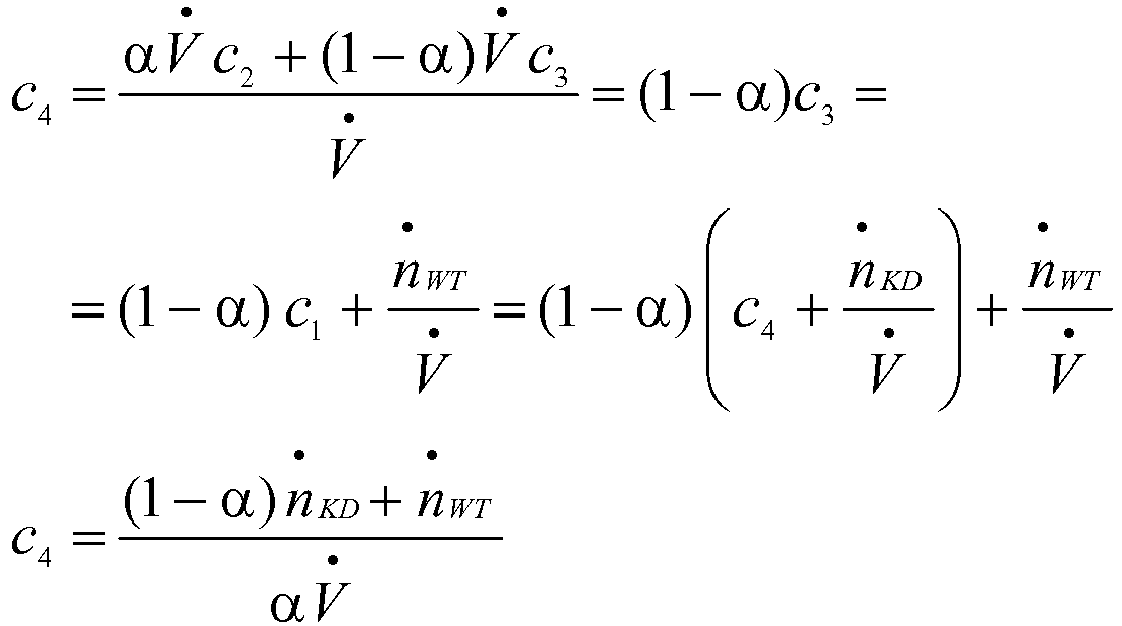
An der folgenden Beispielrechnung soll verdeutlicht werden, wie eine Veränderung des Teilvolumenstroms 12 sich auf die Bildung von Aluminium bzw. auf eine Aluminiumkonzentration im Kühlmedium auswirkt. Dabei seien folgende Größen definiert, die auch in den
- α : Teilvolumenstrom V̇IA /V̇ (einige %)
- V̇ : Gesamtvolumenstrom (m3/s)
- ci : AI-Konzentration (mol/m3) am Ort i
- ṅXY : AI-Eintragsrate (mol/s) durch Komponente XY. Sie ist > 0 bei Al-Abgabe an das Wasser im Fall der Kühldosen und < 0 bei Al-Aufnahme aus dem Kühlwasser im Fall der sich mit Kolloiden belegenden Flächen eines Wärmetauschers.
- α: partial flow rate V̇ IA / V̇ (a few%)
- V̇ : total volume flow (m 3 / s)
- c i : Al concentration (mol / m 3 ) in place i
- ṅ XY : AI entry rate (mol / s) by component XY. It is> 0 for Al discharge to the water in the case of cooling doses and <0 for Al uptake from the cooling water in the case of the colloid-occupying surfaces of a heat exchanger.
Daraus ergibt sich folgende mathematische Überlegung, die sich unmittelbar auf die in 
![]()


![]()
Im Fall der 


Für beide Fälle gilt, dass bei einem niedrigen Teilvolumenstrom 12, bei dem α wesentlich kleiner als 1 ist, die in den Kühldosen 9 und im Wärmetauscher 12 umlaufende Aluminiumkonzentration um den Faktor 1/α >> 1 größer ist, als die durch die Korrosion in der Kühldose 9 und im Wärmetauscher 16 effektiv eingespeiste Aluminiumsättigungskonzentration. Dann sind auch die Aluminiumkonzentrationen vor (c4) und hinter (c1) den Kühldosen 9 vergleichbar groß und entsprechendes ist für die Elektrodenniederschläge vor und hinter den Kühldosen zu erwarten. Die Aluminiumniederschlagsrate auf den Elektroden sollte ungefähr auf den Wert 1/α sinken. Für die Annahme, dass α gegen 1 geht, sind stark verschiedene und stark herabgesetzte Aluminiumkonzentrationen und Niederschlagsraten zu erwarten.For both cases, with a low
Grundsätzlich kann gefolgert werden, dass unabhängig von der Schaltung des Ionenaustauschers 10 im Kühlmittelkreislauf 6 also gemäß der
Claims (8)
Applications Claiming Priority (1)
| Application Number | Priority Date | Filing Date | Title |
|---|---|---|---|
| DE102017204732.1A DE102017204732A1 (en) | 2017-03-21 | 2017-03-21 | Method for operating a cooling device |
Publications (1)
| Publication Number | Publication Date |
|---|---|
| EP3379570A1 true EP3379570A1 (en) | 2018-09-26 |
Family
ID=61906580
Family Applications (1)
| Application Number | Title | Priority Date | Filing Date |
|---|---|---|---|
| EP18162702.7A Withdrawn EP3379570A1 (en) | 2017-03-21 | 2018-03-20 | Method for operating a cooling device |
Country Status (2)
| Country | Link |
|---|---|
| EP (1) | EP3379570A1 (en) |
| DE (1) | DE102017204732A1 (en) |
Cited By (2)
| Publication number | Priority date | Publication date | Assignee | Title |
|---|---|---|---|---|
| US10559519B2 (en) * | 2016-02-04 | 2020-02-11 | Siemens Aktiengesellschaft | Series circuit arrangement of power semiconductors |
| CN114111171A (en) * | 2021-11-12 | 2022-03-01 | 中国南方电网有限责任公司超高压输电公司昆明局 | Converter station cooling system and control method thereof |
Citations (3)
| Publication number | Priority date | Publication date | Assignee | Title |
|---|---|---|---|---|
| US2917685A (en) * | 1957-07-01 | 1959-12-15 | Ite Circuit Breaker Ltd | Recirculating water system for cooling electrical components |
| JPH1189213A (en) * | 1997-09-01 | 1999-03-30 | Mitsubishi Electric Corp | Water cooling equipment for high-voltage electric apparatus |
| DE102014204241A1 (en) * | 2014-03-07 | 2015-09-10 | Siemens Aktiengesellschaft | Cooling device for a converter of a high-voltage direct current transmission system |
Family Cites Families (2)
| Publication number | Priority date | Publication date | Assignee | Title |
|---|---|---|---|---|
| DE2501029A1 (en) | 1974-12-06 | 1976-06-10 | Bbc Brown Boveri & Cie | DEVICE FOR COOLING ELECTRICAL DEVICES AT DIFFERENT ELECTRICAL POTENTIALS BY USING A FLOATING MEDIUM |
| JPS5918666A (en) | 1982-07-22 | 1984-01-31 | Mitsubishi Electric Corp | Cooling device for water cooled apparatus |
-
2017
- 2017-03-21 DE DE102017204732.1A patent/DE102017204732A1/en not_active Withdrawn
-
2018
- 2018-03-20 EP EP18162702.7A patent/EP3379570A1/en not_active Withdrawn
Patent Citations (3)
| Publication number | Priority date | Publication date | Assignee | Title |
|---|---|---|---|---|
| US2917685A (en) * | 1957-07-01 | 1959-12-15 | Ite Circuit Breaker Ltd | Recirculating water system for cooling electrical components |
| JPH1189213A (en) * | 1997-09-01 | 1999-03-30 | Mitsubishi Electric Corp | Water cooling equipment for high-voltage electric apparatus |
| DE102014204241A1 (en) * | 2014-03-07 | 2015-09-10 | Siemens Aktiengesellschaft | Cooling device for a converter of a high-voltage direct current transmission system |
Cited By (2)
| Publication number | Priority date | Publication date | Assignee | Title |
|---|---|---|---|---|
| US10559519B2 (en) * | 2016-02-04 | 2020-02-11 | Siemens Aktiengesellschaft | Series circuit arrangement of power semiconductors |
| CN114111171A (en) * | 2021-11-12 | 2022-03-01 | 中国南方电网有限责任公司超高压输电公司昆明局 | Converter station cooling system and control method thereof |
Also Published As
| Publication number | Publication date |
|---|---|
| DE102017204732A1 (en) | 2018-09-27 |
Similar Documents
| Publication | Publication Date | Title |
|---|---|---|
| DE102008063187B4 (en) | anodizing | |
| DE112009001483T5 (en) | A wire electric discharge machining apparatus and a wire electric discharge machining method, a semiconductor wafer manufacturing apparatus and a semiconductor wafer manufacturing method, and a solar cell wafer manufacturing apparatus and a solar cell wafer manufacturing method | |
| EP3379570A1 (en) | Method for operating a cooling device | |
| DE112011104971T5 (en) | Electricity supply apparatus for electroerosion apparatus and electroerosion method | |
| DE102017118652A1 (en) | Plasma generator module and its use | |
| DE102016110141A1 (en) | Method and device for igniting a plasma load | |
| DE2131473C2 (en) | Conductor arrangement to compensate for harmful magnetic influences from rows of electrolytic cells on neighboring rows of cells | |
| DE3017079A1 (en) | DEVICE FOR ELECTROPLATING | |
| DE102005046720B4 (en) | Process for condensing liquids in a steam turbine | |
| DE102018117059B4 (en) | Battery module for a traction battery of an electrically driven motor vehicle | |
| DE2218612A1 (en) | Rectifier arrangement with cooled power supply | |
| DE112007002875B4 (en) | Device for grounding housings | |
| WO2019243325A1 (en) | Diode laser assembly and dwm module having a diode laser assembly of this type | |
| DE102012200688A1 (en) | Vaporizer plate for cooling lithium-ion hybrid battery, has fluid channel arranged between flow field and fluid outlet for guiding fluid, where fluid channel collects fluid flowing through flow field and passes fluid to fluid outlet | |
| DE102007019981B4 (en) | Anode for the formation of a plasma by forming electrical arcs | |
| EP1033420B1 (en) | Process and apparatus for electrochemically graining a support for light-sensitive layers | |
| LU84372A1 (en) | DEVICE FOR GENERATING A LASER ACTIVE STATE IN A QUICK SUBSURANCE FLOW | |
| EP3176820B1 (en) | Cooling device | |
| DE102014204241A1 (en) | Cooling device for a converter of a high-voltage direct current transmission system | |
| DE102015200245A1 (en) | Cooling device for a converter of a high-voltage direct current transmission system | |
| DE102013212180A1 (en) | Conduit for a fuel cell, fuel cell and fuel cell stack | |
| EP1015671A2 (en) | Method and device for energy saving simultaneous electrolytic treatment of several workpieces | |
| DE102020101331B4 (en) | Inverter device with cooling | |
| WO2016110344A1 (en) | Device for supplying a medium to fuel cells of a fuel cell stack, and fuel cell stack | |
| DE3931570C2 (en) | Arrangement of the cooling water circuit in the direct current circuit of a converter |
Legal Events
| Date | Code | Title | Description |
|---|---|---|---|
| PUAI | Public reference made under article 153(3) epc to a published international application that has entered the european phase |
Free format text: ORIGINAL CODE: 0009012 |
|
| STAA | Information on the status of an ep patent application or granted ep patent |
Free format text: STATUS: THE APPLICATION HAS BEEN PUBLISHED |
|
| AK | Designated contracting states |
Kind code of ref document: A1 Designated state(s): AL AT BE BG CH CY CZ DE DK EE ES FI FR GB GR HR HU IE IS IT LI LT LU LV MC MK MT NL NO PL PT RO RS SE SI SK SM TR |
|
| AX | Request for extension of the european patent |
Extension state: BA ME |
|
| STAA | Information on the status of an ep patent application or granted ep patent |
Free format text: STATUS: REQUEST FOR EXAMINATION WAS MADE |
|
| 17P | Request for examination filed |
Effective date: 20190319 |
|
| RBV | Designated contracting states (corrected) |
Designated state(s): AL AT BE BG CH CY CZ DE DK EE ES FI FR GB GR HR HU IE IS IT LI LT LU LV MC MK MT NL NO PL PT RO RS SE SI SK SM TR |
|
| STAA | Information on the status of an ep patent application or granted ep patent |
Free format text: STATUS: EXAMINATION IS IN PROGRESS |
|
| STAA | Information on the status of an ep patent application or granted ep patent |
Free format text: STATUS: EXAMINATION IS IN PROGRESS |
|
| 17Q | First examination report despatched |
Effective date: 20200713 |
|
| STAA | Information on the status of an ep patent application or granted ep patent |
Free format text: STATUS: THE APPLICATION IS DEEMED TO BE WITHDRAWN |
|
| 18D | Application deemed to be withdrawn |
Effective date: 20201124 |