EP3379504A1 - Cash machine, atm and the like comprising a banknote introduction control device - Google Patents
Cash machine, atm and the like comprising a banknote introduction control device Download PDFInfo
- Publication number
- EP3379504A1 EP3379504A1 EP18163530.1A EP18163530A EP3379504A1 EP 3379504 A1 EP3379504 A1 EP 3379504A1 EP 18163530 A EP18163530 A EP 18163530A EP 3379504 A1 EP3379504 A1 EP 3379504A1
- Authority
- EP
- European Patent Office
- Prior art keywords
- opening
- barrier
- atm
- cash machine
- auxiliary
- Prior art date
- Legal status (The legal status is an assumption and is not a legal conclusion. Google has not performed a legal analysis and makes no representation as to the accuracy of the status listed.)
- Granted
Links
- 230000004888 barrier function Effects 0.000 claims abstract description 58
- 238000000034 method Methods 0.000 claims description 7
- 239000012190 activator Substances 0.000 claims description 4
- 230000004913 activation Effects 0.000 claims 4
- 230000003993 interaction Effects 0.000 claims 2
- 239000002360 explosive Substances 0.000 description 7
- 238000005259 measurement Methods 0.000 description 4
- 239000000126 substance Substances 0.000 description 4
- 238000004519 manufacturing process Methods 0.000 description 2
- 230000001681 protective effect Effects 0.000 description 2
- 229910000831 Steel Inorganic materials 0.000 description 1
- 239000004020 conductor Substances 0.000 description 1
- 230000001419 dependent effect Effects 0.000 description 1
- 238000010586 diagram Methods 0.000 description 1
- 239000012530 fluid Substances 0.000 description 1
- 239000007789 gas Substances 0.000 description 1
- 239000000463 material Substances 0.000 description 1
- 230000003287 optical effect Effects 0.000 description 1
- 239000000843 powder Substances 0.000 description 1
- 238000004064 recycling Methods 0.000 description 1
- 238000007789 sealing Methods 0.000 description 1
- 239000010959 steel Substances 0.000 description 1
Images


Classifications
-
- G—PHYSICS
- G07—CHECKING-DEVICES
- G07F—COIN-FREED OR LIKE APPARATUS
- G07F19/00—Complete banking systems; Coded card-freed arrangements adapted for dispensing or receiving monies or the like and posting such transactions to existing accounts, e.g. automatic teller machines
- G07F19/20—Automatic teller machines [ATMs]
- G07F19/203—Dispensing operations within ATMs
-
- G—PHYSICS
- G07—CHECKING-DEVICES
- G07D—HANDLING OF COINS OR VALUABLE PAPERS, e.g. TESTING, SORTING BY DENOMINATIONS, COUNTING, DISPENSING, CHANGING OR DEPOSITING
- G07D11/00—Devices accepting coins; Devices accepting, dispensing, sorting or counting valuable papers
- G07D11/10—Mechanical details
- G07D11/14—Inlet or outlet ports
-
- G—PHYSICS
- G07—CHECKING-DEVICES
- G07D—HANDLING OF COINS OR VALUABLE PAPERS, e.g. TESTING, SORTING BY DENOMINATIONS, COUNTING, DISPENSING, CHANGING OR DEPOSITING
- G07D11/00—Devices accepting coins; Devices accepting, dispensing, sorting or counting valuable papers
- G07D11/40—Device architecture, e.g. modular construction
-
- G—PHYSICS
- G07—CHECKING-DEVICES
- G07F—COIN-FREED OR LIKE APPARATUS
- G07F19/00—Complete banking systems; Coded card-freed arrangements adapted for dispensing or receiving monies or the like and posting such transactions to existing accounts, e.g. automatic teller machines
- G07F19/20—Automatic teller machines [ATMs]
- G07F19/205—Housing aspects of ATMs
Definitions
- a Cash Machine, ATM and the like comprising a security device, which is secure both during the phase of dispensing and returning banknotes to the safe and which is capable of resisting in the event of attacks using significant quantities of explosives.
- a safe 2 for containing a dispenser or a device for recycling banknotes and valuables defining an inner volume 2a , and an outer face 7.
- the outer face 7 comprises means for interacting with the public of a known type, such as a screen, a keypad, a slit for introducing a card and a slit for introducing and withdrawing banknotes and valuables described below, as well as others.
- the auxiliary openings 4a can comprise a first auxiliary opening 40a and/or a second auxiliary opening 40b.
- the auxiliary opening 4a are kept open, in the case of the first auxiliary opening 40a to not compress or sever the electrical connection 6 connected to the inner volume 2a said conveying device 3 and, in the case of the second auxiliary opening 40b so as to allow the movement of the first portion 51 avoiding the interference of other objects, i.e.: the guides 10, within the trajectory of the first portion 51.
- the first auxiliary opening 40a is preferably suitable to allow the passage of a vertical flat cable, and it is preferably in the upper part of the first barrier 50.
- the first auxiliary portion 53a is also preferably in proximity to the wall of the safe 2, so it can be constrained to the same wall of the safe 2 or also arranged internally on the basket or other.
- the two portions 51 and 52 or 53 are both connected respectively by first and second moving means 51a and 52a integrated with a device adjacent to the wall, or inside the wall, of the safe 2e.
- the first and second moving means 51a and 52a are preferably linear actuators, preferably endless screw type.
- Said movable barriers thus described, can be realized using overlapping ballistic and drill-proof steel, so as to resist robbery attempts carried out using heavy vehicles and explosives placed outside Cash Machines, ATMs or the like, keeping the safe inaccessible.
Abstract
Description
- The present invention relates to a Cash Machine, ATM and the like comprising a banknote introduction control device of the type specified in the preamble of the first claim.
- Distributors of banknotes or valuables are currently known, such as, in particular Cash Machines or ATMs or systems for dispensing and accepting banknotes.
- They comprise a safe suitable to contain banknotes and valuables and control means suitable to dispense banknotes and valuables to an authorized user. The dispensing of banknotes and valuables takes place once the user has been identified by means of code cards or the like, and it takes place by means of a dispenser mouth, communicating with the inside of the safe, suitable to dispense banknotes or values to the external user.
- Therefore, dispenser mouths are generally designed for public areas, accessible to users.
- This component constitutes the end part of a dispenser channel comprising an elongated body for the passage of the banknotes and valuables entering or leaving the safe. Inside the safe, there is a dispenser where the banknotes are stored. An elongated body, in correspondence with the outer face exposed to the public, comprises a slit or the like through which the valuables and banknotes, usually grouped into bundles, are introduced.
- Furthermore, the dispenser channels comprise a conveying device generally consisting of an element adapted to convey or push the banknotes along the elongated body in the direction of the customer side external mouth.
- In particular, in the case of Cash Machines or ATMs, these methods of moving and dispensing banknotes are efficient and extremely common.
- However, they present one drawback: they allow explosive substances to be introduced into the safe through the dispenser mouth of the automatic distributor.
- In fact, one possible theft attempt perpetrated on the armoured casing of automatic dispensers of banknotes and valuables comprises that, in the same, a fluid, powder or nevertheless an explosive substance is inserted directly into the safe through the dispenser mouth.
- In particular, the criminals equipped themselves with special instruments or cables having a length greater than the length of the elongated body, so as to allow the introduction of said substances passing: the external mouth, the entire elongated body and the internal opening of the safe.
- Various apparatus has been developed to overcome this drawback, comprising a protective mechanical barrier suitable to prevent the introduction of gases or explosives passing through the dispenser mouth. Such protective barrier doesn't serve to prevent said actions, because it must be opened in correspondence with a disbursement of banknotes and valuables.
- Such further drawback was remedied, in particular, in patent applications
IT MI2004A001683 IT MI2003A000342 - The two barriers are usually always closed and, in the dispensing phase, they only open one at a time, so that one of the two openings is always closed.
- However, such security always adapts badly in the previously described Cash Machine, ATM models and the like. In particular, when shuttles or conveying pockets are used, connected by cables or connections needed to connect to the electronics positioned inside the safe.
- Therefore, this second barrier, which closes the safe, cannot always be totally closed in correspondence with a disbursement.
- In this situation the technical task underlying the present invention is to develop a Cash Machine, ATM and the like comprising a banknote introduction control device capable of substantially overcoming at least part of the stated drawbacks.
- In the scope of said technical task it is an important object of the invention to obtain a Cash Machine, ATM and the like comprising a security device, which is secure both during the phase of dispensing and returning banknotes to the safe and which is capable of resisting in the event of attacks using significant quantities of explosives.
- The technical task and specified objects are achieved with a Cash Machine, ATM and the like comprising a banknote introduction control device, as claimed in the appended claim 1.
- Preferred embodiments are described in the dependent claims.
- The characteristics and advantages of the invention are clarified below by the detailed description of preferred embodiments of the invention, with reference to the appended drawings, wherein:
-
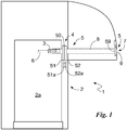
Fig. 1 shows a diagram of a Cash Machine, ATM or the like according to the invention; -
Fig. 2a illustrates a portion of Cash Machine, ATM or the like according to the invention in a first configuration; -
Fig. 2b is the portion inFig. 2a in a second configuration; -
Fig. 2c shows the portion inFig. 2a in a third configuration; -
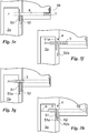
Figures 3a-3h show the sequence of operations performed by the banknote introduction control device according to the invention, -
Fig. 4a illustrates a portion of a second embodiment of a Cash Machine, ATM or the like according to the invention in a first configuration; -
Fig. 4b is the portion inFig. 4a in a second configuration; -
Fig. 4c shows the portion inFig. 4a in a third configuration; -
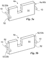
Fig. 5a illustrates a portion of the second embodiment of a Cash Machine, ATM or the like according to the invention in a first configuration; -
Fig. 5b is the portion inFig. 5a in a second configuration; - In this document, when measurements, values, shapes and geometrical references (such as perpendicularity and parallelism) are associated with words, such as "approximately" or other similar terms, for example "practically" or "substantially", they are to be understood as except for errors of measurement or inaccuracies resulting from production and/or manufacturing errors and, above all, except for a slight divergence from the value, measurement, shape or geometrical reference with which it is associated. For example, if said terms are associated with a value, they preferably indicate a divergence of no more than 10% of the same value.
- Furthermore, when terms such as "first", "second", "greater", "lower", "principal" and "secondary" are used, they do not necessarily identify an order, a relationship priority or relative position, but they may simply be used to distinguish different components more clearly.
- Unless otherwise indicated, the measurements and data contained in this document shall be considered as carried out in International Standard Atmosphere ICAO (ISO 2533:1975).
- With reference to the Figures, the Cash Machine, ATM or the like according to the invention is globally indicated with number 1.
- In short, it comprises a safe 2 for containing a dispenser or a device for recycling banknotes and valuables defining an
inner volume 2a, and anouter face 7. - More specifically, the safe 2 is known in itself and comprises drawers, suitable to contain the various denominations of banknotes. Furthermore, the safe 2 isn't always placed in direct contact with the
outer face 7, but, in many cases, it is distant from the same by approximately half a meter. - The
outer face 7 comprises means for interacting with the public of a known type, such as a screen, a keypad, a slit for introducing a card and a slit for introducing and withdrawing banknotes and valuables described below, as well as others. - The Cash Machine, ATM or the like 1 comprises a
conveying device 3, suitable to convey banknotes and valuables from theinner volume 2a to the outside and vice versa, in particular in correspondence with theouter face 7. Preferably, theconveying device 3 substantially consists of a movable body moved byspecial guides 10 or racks or moving belts driven, in turn, by electric motors. In many cases, theconveying device 3 is also connected by electrical connections orcables 6 to electrical and/or electronic control devices housed inside 2a the safe 2. Saidelectrical connection 6 consists of a cable or electrical conductors. Said cable is preferably a flat-cable, in other words, a cable of a flat type, preferably arranged with the main extension direction of the normal section preferably vertical. In this way, the cable folds over and rolls and unrolls on itself, when the conveying device extends indirection 7, passing through theopening 4. - The safe 2 normally comprises an
opening 4, suitable to allow the passage of theconveying device 3 and, consequently, the transfer of banknotes and valuables from theinner volume 2a, passing the first barrier towards the second 9, placed on the external customer side. - The
opening 4 is preferably crossed by anelongated body 8 defining a passage between the opening 4 and a dispenser mouth 9, placed on theouter face 7. More specifically, theelongated body 8 is a body whose dimensions are suitable to allow the transport of the banknotes, defining an inner channel 8a. Thus, theelongated body 8 is the space along which the conveyingdevice 3 is moved 3. - The Cash Machine, ATM or the like 1 preferably comprises a
security device 5 suitable to close, at least partially, theopening 4. - The security device comprises a first barrier, inside or outside the safe 50, for the opening of the
passage 4, and asecond barrier 59, suitable to close the dispenser mouth 9. - Advantageously, the
first barrier 50 is ready, waiting for a dispensing request on command in: a closed configuration and in an open configuration, waiting for the passage of the shuttle, and a conveying configuration or partially closed configuration after the passage of the conveyingmeans 3. - In the open configuration (
Figures 2b ,3b ,3g ), thefirst barrier 50 keeps theopening 4 fully open for the passage of the conveyingdevice 3. In the closed configuration (Figures 2a ,3a ,3h ), thefirst barrier 50 closes theopening 4 completely, or at least by 70% or better, by 80% or even better, by 90%. In the conveying configuration (Fig. 2c ,3c-3f ), theopening 4, is closed and at least oneauxiliary opening 4a is kept open. - The
auxiliary openings 4a can comprise a firstauxiliary opening 40a and/or a secondauxiliary opening 40b. Theauxiliary opening 4a are kept open, in the case of the firstauxiliary opening 40a to not compress or sever theelectrical connection 6 connected to theinner volume 2a said conveyingdevice 3 and, in the case of the secondauxiliary opening 40b so as to allow the movement of thefirst portion 51 avoiding the interference of other objects, i.e.: theguides 10, within the trajectory of thefirst portion 51. - The first
auxiliary opening 40a is preferably suitable to allow the passage of a vertical flat cable, and it is preferably in the upper part of thefirst barrier 50. - The second
auxiliary opening 40b is preferably suitable to allow the movement of thefirst portion 51 avoiding the interference of other objects, i.e.: theguides 10, within the trajectory of thefirst portion 51. Therefore, it is preferably placed at the sides of thebarrier 50. - Structurally, the
first barrier 50 preferably comprises: afirst portion 51 consisting of a barrier movable with respect to theopening 4, suitable to partially close theopening 4 and comprising, preferably, a slit defining theauxiliary opening 4a and at least oneauxiliary portion 52 consisting of a barrier movable with respect to both theopening 4 and thefirst portion 51 and suitable to close theauxiliary opening 4a. Thefirst portions 51 is preferably in proximity to the wall of the safe 2, so it can be constrained to the same wall of the safe 2 or also arranged internally on the basket or other. - The
auxiliary portion 52 comprises at least a first auxiliary portion 53a. - The first auxiliary portion 53a is suitable to close the first
auxiliary opening 40a, and preferably moves substantially parallel with thefirst portion 51 and also in the same direction. - The first auxiliary portion 53a is also preferably in proximity to the wall of the safe 2, so it can be constrained to the same wall of the safe 2 or also arranged internally on the basket or other.
- The second
auxiliary portion 53b is suitable to close, at least partially, the secondauxiliary opening 40b, and preferably moves not parallel, more preferably substantially perpendicular, to thefirst portion 51 and also preferably in the same direction. - Preferably, the two
portions - Preferably, the second moving means 52a of the second
auxiliary portion 53b are fixed on saidfirst portion 51. - The
security device 5 can also comprise tampering sensor means and/or alarm means, known per se, such as, for example the ones described in the same applicant's patentEP-B-2648168 from Paragraph 17 to paragraph 55 and inFigures 1a-4 and considered incorporated herein for reference. The sensor means can be chosen, for example, among one or more of: system with photocells, accelerometers, inclination sensors, sensor along the presentation path of the banknotes, sensors on the external face of the Cash Machines, ATMs and the like. The working of Cash Machines, ATMs and the like 1, previously described in structural terms, is as follows. Said working defines an innovative security procedure for safes, Cash Machines, ATMs and the like 1. - When not in use, while no request for banknotes and valuables is being made by a user from the Cash Machine, ATM and the like 1, the
first barrier 50 is in a closed configuration (Fig. 3A ) and so theopening 4 is completely closed without presenting easy access points for introducing explosives or for mechanical forcing or other. Furthermore, in such conditions, the conveyingdevice 3 is inside theinner volume 2a and so theelectrical connection 6 doesn't have to pass theopening 4. Furthermore, again, when not in use, thesecond barrier 59 also remains closed and closes the dispenser mouth 9. - When a user requests banknotes and valuables and performs the usual procedures for identification in front of the
outer face 7 of the Cash Machine, ATM and the like 1 and the system authorizes the issue of legally requested banknotes and valuables. In this case, opportunely, the secondouter barrier 59 remains closed with the dispenser mouth 9 closed, while thefirst barrier 50 positions itself in an open configuration (Figures 2b ,3b ), so as to allow the free passage of the conveyingdevice 3 through theopening 4. - When the conveying
device 3, carrying the banknotes and valuables, passes theopening 4 and positions itself in theelongated body 8, theelectrical connection 6 also passes theopening 4. - In such conditions, while the
second barrier 59 remains closed, thefirst barrier 50 positions itself in a conveying configuration (Figures 2c ,3c ), so that theauxiliary opening 4a stays open and theelectrical connection 6 between the conveyingmeans 3 and theinner volume 2a is not interrupted. At the same time, most of the surface of theopening 4 is closed by thefirst portion 51. Operatively, to arrange thefirst barrier 50 in a conveying configuration (Fig. 2c ) only the first moving means 51a are activated, which move thefirst portion 51, while theauxiliary portion 52 stays still. - Thus, the conveying
device 3, carrying the banknotes and valuables, passes the entireelongated body 8 and reaches the second barrier 59 (Fig. 3d ). The latter is thus opened (Fig. 3e ) to allow the disbursement of the banknotes and valuables to the claimant. At the same time, thefirst barrier 50 stays in a conveying configuration (Fig. 2c ) and, sealing most of theopening 4 and interposed between the conveyingmeans 3, prevents the introduction of substances into theinner volume 4a. - Substantially, during the passage of the conveying
device 3 from theinner volume 2a to the dispenser mouth 9, at least one from among thesecond barrier 59 and thefirst portion 51 of thefirst barrier 50 is in a closed position. - Once the banknotes have been dispensed, the conveying
device 3 withdraws, the secondouter barrier 59 closes (Fig. 3f ) and remains closed until the next disbursement, the conveyingdevice 3 passes theelongated body 8, thefirst barrier 50 positions itself in an open configuration (Fig. 2b ) and the conveyingdevice 3 passes the opening 4 (Fig. 3g ) and stays in theinner volume 2a. Then, thefirst barrier 50 positions itself in a closed configuration (Fig. 2a ). Substantially, the device returns to a state of waiting for a new disbursement (Fig. 3h ). - If, during operation of the Cash Machine, ATM and the like 1, the
first barrier 50 was in a conveying configuration (Fig. 2c ,4c ), or also in an open configuration (Fig. 2b ,4b ), and the alarm means and/or tampering sensors, such as accelerometers or optical sensor or other, serving the same Cash Machine, ATM and the like 1, signalled a state of danger or a disturbance or unjustified movement, thefirst barrier 50 immediately position itself in a closed configuration (Fig. 2a ,4a ) regardless of the presence, or not, of theelectrical connection 6 through theauxiliary opening 4a. The word "position" means that, if the barrier was in a closed configuration, it stays in this configuration, or if the barrier was in other configurations it moves and close in closed configuration. - Moreover, this closing also using rapid actuation means, such as, pyrotechnic activators and/or a piston and/or snap activators, and at the cost of breaking, or damaging the
electrical connection 6 itself. - The Cash Machine, ATM and the like 1 according to the invention brings important advantages.
- In fact, the same allows maximum security of the safe to be maintained in all conditions.
- In particular, if the robbery attempt is carried out skilfully, also during the operations of conveying the banknotes and valuables, the double alternation of the
first barrier 50 and thesecond barrier 59 prevents explosives from being introduced into the safe 2. - Said movable barriers, thus described, can be realized using overlapping ballistic and drill-proof steel, so as to resist robbery attempts carried out using heavy vehicles and explosives placed outside Cash Machines, ATMs or the like, keeping the safe inaccessible.
- The invention is subject to variations falling within the scope of the inventive concept defined by the claims. In such scope, all of the details can be replaced with equivalent components and any materials, shapes and sizes can be used.
- For example, said barriers can be composed of continuous plates or grills or pistons or other.
Claims (15)
- Cash machine, ATM and the like (1) comprising:- a safe (2) defining an inner volume (2a),- a conveying device (3), suitable to convey banknotes and valuables from said inner volume (2a) to the outside and / or vice versa,- an opening (4) of said safe (2), suitable to allow the passage of said conveying device (3),- a security device (5) suitable to close at least partially said opening (4),and characterised in that- said security device (5) comprises a first barrier (50) for said opening (4), said first barrier (50) comprising:- a first portion (51) consisting of a barrier movable with respect to said opening (4), suitable to partially close said opening (4) and comprising at least one auxiliary opening (4a),- at least one auxiliary portion (52) consisting of a barrier movable with respect to said opening (4) and to said first portion (51) and suitable to close at least one of said auxiliary opening (4a).
- Cash machine, ATM and the like (1) according to the preceding claim, wherein said first barrier (50) is available in:- an open configuration, in which said first barrier (50) keeps said opening (4) open for the passage of said conveying device (3),- a closed configuration, in which said first barrier (50) closes totally, or at least by 70%, said opening (4),- a conveying configuration, in which said opening (4), is only partially closed, and an auxiliary opening (4a, 4b) is kept open.
- Cash machine, ATM and the like (1) according to at least one preceding claim, wherein said auxiliary opening (4a) comprises a first auxiliary opening (40a) suitable for allowing the passage of an electrical connection (6) from said inner volume (2a) to said conveying device (3).
- Cash machine, ATM and the like (1) according to at least one preceding claim, wherein said first portion (51) comprises a slit defining said first auxiliary opening (40a).
- Cash machine, ATM and the like (1) according to at least one preceding claim, wherein said auxiliary opening (4a) comprises a second auxiliary opening (40b) suitable for allowing the movement of said first portion (51) avoiding the interference of other objects within the trajectory of said first portion (51).
- Cash machine, ATM and the like (1) according to the preceding claim, wherein said auxiliary portion (52) comprises a second auxiliary portion (53b), suitable to cover, at least partially, said second auxiliary opening (40b) and movable in direction not parallel to the trajectory of said first portion (51).
- Cash machine, ATM and the like (1) according to the preceding claim, wherein said second auxiliary portion (53b) is movably fixed on said first portion (51).
- Cash machine, ATM and the like (1) according to the preceding claim, comprising first and auxiliary moving means (51a, 52a) respectively connected to said first and auxiliary portions (51, 52) and in proximity to a wall of said safe (2), said first and second moving means (51a, 52a) being suitable to move said respective portion (51, 52) independently of one another.
- Cash machine, ATM and the like (1) according to at least one preceding claim, comprising an outer interaction side (7) with the public, a dispenser mouth (9) for said banknotes and valuables, placed on said outer side (7), and an elongated body (8), connecting said opening (4) with said dispenser mouth (9) and defining a main space along which said conveying device (3) is moved.
- Cash machine, ATM and the like (1) according to the preceding claim, comprising a second barrier (59), suitable to close said dispenser mouth (9).
- Cash machine, ATM and the like (1) according to at least one of the claims 2-7, comprising rapid actuation means for said auxiliary portion (52) suitable to close said auxiliary opening (4a) quickly in the event of an alarm.
- Cash machine, ATM and the like (1) according to the preceding claim, wherein said quick actuation means of said auxiliary portion (52) are selected from pyrotechnic activators and snap activators.
- Activation method of a cash machine, ATM and the like (1), said cash machine, ATM and the like (1) comprising,- a safe (2) defining an inner volume (2a),- a conveying device (3), suitable to convey banknotes and valuables from said inner volume (2a) to the outside and / or vice versa,- an opening (4) of said safe (2), suitable to allow the passage of said conveying device (3),- a security device (5) suitable to close at least partially said opening (4),said activation method being characterised in that, in conditions of non-use, said first barrier (50) is arranged in the closed configuration.
said security device (5) comprising a first barrier (50) for said opening (4), said first barrier (50) being available in:- an open configuration, in which said first barrier (50) keeps said opening (4) open for the passage of said conveying device (3),- a closed configuration, in which said first barrier (50) closes totally, or at least by 70%, said opening (4),- a conveying configuration, in which said opening (4), is only partially closed, and an auxiliary opening (4a) is kept open, - Activation method of a cash machine, ATM and the like (1) according to the preceding claim, wherein said cash machine, ATM and the like (1) comprises alarm means and/or tampering sensors and/or accelerometers or the like and wherein, when said means signal a condition of danger or tampering, said first barrier (50) is arranged in the closed configuration regardless of the position of said electrical connection (6).
- Activation method of a cash machine, ATM and the like (1) according to claim 13 or 14, wherein said cash machine, ATM and the like (1) comprises an outer interaction face (7) with the public, a dispenser mouth (9) for said banknotes and valuables, placed on said outer face (7), an elongated body (8), connecting said opening (4) with said dispenser mouth (9) and defining a main space along which said conveying device (3) is moved and a second barrier (59), suitable to close said dispenser mouth (9), and wherein, during the passage of said conveying device (3) from said inner volume (2a) to said dispenser mouth (9), at least one out of said second barrier (59) and said first portion (51) is in the closed position.
Applications Claiming Priority (1)
| Application Number | Priority Date | Filing Date | Title |
|---|---|---|---|
| IT102017000032227A IT201700032227A1 (en) | 2017-03-23 | 2017-03-23 | BANCOMAT, ATM AND SIMILAR INCLUDING A BANKNOTES PRESENTATION CONTROL DEVICE |
Publications (2)
| Publication Number | Publication Date |
|---|---|
| EP3379504A1 true EP3379504A1 (en) | 2018-09-26 |
| EP3379504B1 EP3379504B1 (en) | 2023-06-14 |
Family
ID=59683671
Family Applications (1)
| Application Number | Title | Priority Date | Filing Date |
|---|---|---|---|
| EP18163530.1A Active EP3379504B1 (en) | 2017-03-23 | 2018-03-23 | Cash machine, atm and the like comprising a banknote introduction control device |
Country Status (3)
| Country | Link |
|---|---|
| EP (1) | EP3379504B1 (en) |
| ES (1) | ES2962776T3 (en) |
| IT (1) | IT201700032227A1 (en) |
Cited By (4)
| Publication number | Priority date | Publication date | Assignee | Title |
|---|---|---|---|---|
| CN109326060A (en) * | 2018-11-02 | 2019-02-12 | 国网四川省电力公司广安供电公司 | A kind of electric power self-service payment terminal Intelligent remote monitoring system |
| EP3664051A1 (en) * | 2018-12-04 | 2020-06-10 | Hyosung Tns Inc. | Automated teller machine having bill stopper |
| IT201900003745A1 (en) * | 2019-03-14 | 2020-09-14 | M I B S R L | ATM, BANCOMAT, IMPROVED SECURITY WITH MULTIPLE INTERLOCKING ALONG THE BANKNOTE PRESENTATION PATH |
| US11217069B1 (en) * | 2020-06-17 | 2022-01-04 | Hyosung TNS Inc. | Automated teller machine |
Citations (2)
| Publication number | Priority date | Publication date | Assignee | Title |
|---|---|---|---|---|
| EP2120222A2 (en) * | 2008-05-07 | 2009-11-18 | M.I.B. S.p.A. | Automatic Teller Machine |
| EP2648168A1 (en) * | 2012-04-03 | 2013-10-09 | M.I.B. S.r.L. | Cash dispenser |
-
2017
- 2017-03-23 IT IT102017000032227A patent/IT201700032227A1/en unknown
-
2018
- 2018-03-23 ES ES18163530T patent/ES2962776T3/en active Active
- 2018-03-23 EP EP18163530.1A patent/EP3379504B1/en active Active
Patent Citations (3)
| Publication number | Priority date | Publication date | Assignee | Title |
|---|---|---|---|---|
| EP2120222A2 (en) * | 2008-05-07 | 2009-11-18 | M.I.B. S.p.A. | Automatic Teller Machine |
| EP2648168A1 (en) * | 2012-04-03 | 2013-10-09 | M.I.B. S.r.L. | Cash dispenser |
| EP2648168B1 (en) | 2012-04-03 | 2016-07-27 | M.I.B. S.r.L. | Cash dispenser |
Cited By (5)
| Publication number | Priority date | Publication date | Assignee | Title |
|---|---|---|---|---|
| CN109326060A (en) * | 2018-11-02 | 2019-02-12 | 国网四川省电力公司广安供电公司 | A kind of electric power self-service payment terminal Intelligent remote monitoring system |
| EP3664051A1 (en) * | 2018-12-04 | 2020-06-10 | Hyosung Tns Inc. | Automated teller machine having bill stopper |
| US10885750B2 (en) | 2018-12-04 | 2021-01-05 | Hyosung TNS Inc. | Automated teller machine having bill stopper |
| IT201900003745A1 (en) * | 2019-03-14 | 2020-09-14 | M I B S R L | ATM, BANCOMAT, IMPROVED SECURITY WITH MULTIPLE INTERLOCKING ALONG THE BANKNOTE PRESENTATION PATH |
| US11217069B1 (en) * | 2020-06-17 | 2022-01-04 | Hyosung TNS Inc. | Automated teller machine |
Also Published As
| Publication number | Publication date |
|---|---|
| EP3379504B1 (en) | 2023-06-14 |
| ES2962776T3 (en) | 2024-03-21 |
| IT201700032227A1 (en) | 2018-09-23 |
Similar Documents
| Publication | Publication Date | Title |
|---|---|---|
| EP3379504B1 (en) | Cash machine, atm and the like comprising a banknote introduction control device | |
| US5156272A (en) | Device for defacing valuable documents and cases for automatic banknote dispensers fitted with such device | |
| CA2379865C (en) | Security cabinet, combined security unit and pick unit, and atm including such an arrangement | |
| EP2648168B1 (en) | Cash dispenser | |
| EP2510506B1 (en) | A security apparatus | |
| EP3117408B1 (en) | Cash spoiling system | |
| SE429693B (en) | SEKERHETSKASSETT | |
| US20100117844A1 (en) | Manipulation Detection System for Removable Money Cassettes for Use in Automated Teller Machines | |
| GB2081807A (en) | Automatic banking machine having a security container | |
| SE459532B (en) | Banknote or bank vending machine with lockable and lockable container, which can be readable insertable in the vending machine | |
| US9127495B2 (en) | Secure enclosure | |
| WO2001029786A1 (en) | A container for valuables | |
| US6325370B1 (en) | Automatic banknote selection and delivery safe | |
| GB2360327A (en) | Security system having a plurality of restricted access compartments | |
| IT201900012474A1 (en) | Security system for bank ATMs | |
| EP3455832A1 (en) | Security device for atm | |
| ITMI940062A1 (en) | DEVICE FOR THE CONTROLLED CONTAINMENT OF BANKNOTES AND VALUES | |
| KR100555953B1 (en) | Apparatus for paying copper coin and paper money on account | |
| ITMI992603A1 (en) | DEVICE AND PROCEDURE FOR THE CASE AND AUTOMATED DELIVERY OF MONEY AND VALUES IN ENVELOPES EQUIPPED WITH IDENTIFICATION ELEMENTS | |
| CN113168745A (en) | Document transport path without idler roller | |
| ITMI940185A1 (en) | ANTI-COUNTER DEVICE AND PROCEDURE IN PARTICULAR FOR AUTOMATIC BANKNOTE AND VALUE DISTRIBUTORS | |
| ITMI20091437A1 (en) | DISTRIBUTOR APPARATUS OF BANKNOTES AND VALUES |
Legal Events
| Date | Code | Title | Description |
|---|---|---|---|
| PUAI | Public reference made under article 153(3) epc to a published international application that has entered the european phase |
Free format text: ORIGINAL CODE: 0009012 |
|
| STAA | Information on the status of an ep patent application or granted ep patent |
Free format text: STATUS: THE APPLICATION HAS BEEN PUBLISHED |
|
| AK | Designated contracting states |
Kind code of ref document: A1 Designated state(s): AL AT BE BG CH CY CZ DE DK EE ES FI FR GB GR HR HU IE IS IT LI LT LU LV MC MK MT NL NO PL PT RO RS SE SI SK SM TR |
|
| AX | Request for extension of the european patent |
Extension state: BA ME |
|
| STAA | Information on the status of an ep patent application or granted ep patent |
Free format text: STATUS: REQUEST FOR EXAMINATION WAS MADE |
|
| 17P | Request for examination filed |
Effective date: 20190222 |
|
| RBV | Designated contracting states (corrected) |
Designated state(s): AL AT BE BG CH CY CZ DE DK EE ES FI FR GB GR HR HU IE IS IT LI LT LU LV MC MK MT NL NO PL PT RO RS SE SI SK SM TR |
|
| STAA | Information on the status of an ep patent application or granted ep patent |
Free format text: STATUS: EXAMINATION IS IN PROGRESS |
|
| 17Q | First examination report despatched |
Effective date: 20200514 |
|
| STAA | Information on the status of an ep patent application or granted ep patent |
Free format text: STATUS: EXAMINATION IS IN PROGRESS |
|
| STAA | Information on the status of an ep patent application or granted ep patent |
Free format text: STATUS: EXAMINATION IS IN PROGRESS |
|
| GRAP | Despatch of communication of intention to grant a patent |
Free format text: ORIGINAL CODE: EPIDOSNIGR1 |
|
| STAA | Information on the status of an ep patent application or granted ep patent |
Free format text: STATUS: GRANT OF PATENT IS INTENDED |
|
| INTG | Intention to grant announced |
Effective date: 20230403 |
|
| GRAS | Grant fee paid |
Free format text: ORIGINAL CODE: EPIDOSNIGR3 |
|
| GRAA | (expected) grant |
Free format text: ORIGINAL CODE: 0009210 |
|
| STAA | Information on the status of an ep patent application or granted ep patent |
Free format text: STATUS: THE PATENT HAS BEEN GRANTED |
|
| AK | Designated contracting states |
Kind code of ref document: B1 Designated state(s): AL AT BE BG CH CY CZ DE DK EE ES FI FR GB GR HR HU IE IS IT LI LT LU LV MC MK MT NL NO PL PT RO RS SE SI SK SM TR |
|
| REG | Reference to a national code |
Ref country code: CH Ref legal event code: EP |
|
| REG | Reference to a national code |
Ref country code: DE Ref legal event code: R096 Ref document number: 602018051761 Country of ref document: DE |
|
| REG | Reference to a national code |
Ref country code: AT Ref legal event code: REF Ref document number: 1579790 Country of ref document: AT Kind code of ref document: T Effective date: 20230715 |
|
| REG | Reference to a national code |
Ref country code: LT Ref legal event code: MG9D |
|
| REG | Reference to a national code |
Ref country code: NL Ref legal event code: MP Effective date: 20230614 |
|
| PG25 | Lapsed in a contracting state [announced via postgrant information from national office to epo] |
Ref country code: SE Free format text: LAPSE BECAUSE OF FAILURE TO SUBMIT A TRANSLATION OF THE DESCRIPTION OR TO PAY THE FEE WITHIN THE PRESCRIBED TIME-LIMIT Effective date: 20230614 Ref country code: NO Free format text: LAPSE BECAUSE OF FAILURE TO SUBMIT A TRANSLATION OF THE DESCRIPTION OR TO PAY THE FEE WITHIN THE PRESCRIBED TIME-LIMIT Effective date: 20230914 |
|
| REG | Reference to a national code |
Ref country code: AT Ref legal event code: MK05 Ref document number: 1579790 Country of ref document: AT Kind code of ref document: T Effective date: 20230614 |
|
| PG25 | Lapsed in a contracting state [announced via postgrant information from national office to epo] |
Ref country code: RS Free format text: LAPSE BECAUSE OF FAILURE TO SUBMIT A TRANSLATION OF THE DESCRIPTION OR TO PAY THE FEE WITHIN THE PRESCRIBED TIME-LIMIT Effective date: 20230614 Ref country code: NL Free format text: LAPSE BECAUSE OF FAILURE TO SUBMIT A TRANSLATION OF THE DESCRIPTION OR TO PAY THE FEE WITHIN THE PRESCRIBED TIME-LIMIT Effective date: 20230614 Ref country code: LV Free format text: LAPSE BECAUSE OF FAILURE TO SUBMIT A TRANSLATION OF THE DESCRIPTION OR TO PAY THE FEE WITHIN THE PRESCRIBED TIME-LIMIT Effective date: 20230614 Ref country code: LT Free format text: LAPSE BECAUSE OF FAILURE TO SUBMIT A TRANSLATION OF THE DESCRIPTION OR TO PAY THE FEE WITHIN THE PRESCRIBED TIME-LIMIT Effective date: 20230614 Ref country code: HR Free format text: LAPSE BECAUSE OF FAILURE TO SUBMIT A TRANSLATION OF THE DESCRIPTION OR TO PAY THE FEE WITHIN THE PRESCRIBED TIME-LIMIT Effective date: 20230614 |
|
| REG | Reference to a national code |
Ref country code: GR Ref legal event code: EP Ref document number: 20230401627 Country of ref document: GR Effective date: 20231113 |
|
| PG25 | Lapsed in a contracting state [announced via postgrant information from national office to epo] |
Ref country code: FI Free format text: LAPSE BECAUSE OF FAILURE TO SUBMIT A TRANSLATION OF THE DESCRIPTION OR TO PAY THE FEE WITHIN THE PRESCRIBED TIME-LIMIT Effective date: 20230614 |
|
| PG25 | Lapsed in a contracting state [announced via postgrant information from national office to epo] |
Ref country code: SK Free format text: LAPSE BECAUSE OF FAILURE TO SUBMIT A TRANSLATION OF THE DESCRIPTION OR TO PAY THE FEE WITHIN THE PRESCRIBED TIME-LIMIT Effective date: 20230614 |
|
| PG25 | Lapsed in a contracting state [announced via postgrant information from national office to epo] |
Ref country code: IS Free format text: LAPSE BECAUSE OF FAILURE TO SUBMIT A TRANSLATION OF THE DESCRIPTION OR TO PAY THE FEE WITHIN THE PRESCRIBED TIME-LIMIT Effective date: 20231014 |
|
| PG25 | Lapsed in a contracting state [announced via postgrant information from national office to epo] |
Ref country code: SM Free format text: LAPSE BECAUSE OF FAILURE TO SUBMIT A TRANSLATION OF THE DESCRIPTION OR TO PAY THE FEE WITHIN THE PRESCRIBED TIME-LIMIT Effective date: 20230614 Ref country code: SK Free format text: LAPSE BECAUSE OF FAILURE TO SUBMIT A TRANSLATION OF THE DESCRIPTION OR TO PAY THE FEE WITHIN THE PRESCRIBED TIME-LIMIT Effective date: 20230614 Ref country code: RO Free format text: LAPSE BECAUSE OF FAILURE TO SUBMIT A TRANSLATION OF THE DESCRIPTION OR TO PAY THE FEE WITHIN THE PRESCRIBED TIME-LIMIT Effective date: 20230614 Ref country code: PT Free format text: LAPSE BECAUSE OF FAILURE TO SUBMIT A TRANSLATION OF THE DESCRIPTION OR TO PAY THE FEE WITHIN THE PRESCRIBED TIME-LIMIT Effective date: 20231016 Ref country code: IS Free format text: LAPSE BECAUSE OF FAILURE TO SUBMIT A TRANSLATION OF THE DESCRIPTION OR TO PAY THE FEE WITHIN THE PRESCRIBED TIME-LIMIT Effective date: 20231014 Ref country code: EE Free format text: LAPSE BECAUSE OF FAILURE TO SUBMIT A TRANSLATION OF THE DESCRIPTION OR TO PAY THE FEE WITHIN THE PRESCRIBED TIME-LIMIT Effective date: 20230614 Ref country code: CZ Free format text: LAPSE BECAUSE OF FAILURE TO SUBMIT A TRANSLATION OF THE DESCRIPTION OR TO PAY THE FEE WITHIN THE PRESCRIBED TIME-LIMIT Effective date: 20230614 Ref country code: AT Free format text: LAPSE BECAUSE OF FAILURE TO SUBMIT A TRANSLATION OF THE DESCRIPTION OR TO PAY THE FEE WITHIN THE PRESCRIBED TIME-LIMIT Effective date: 20230614 |
|
| PG25 | Lapsed in a contracting state [announced via postgrant information from national office to epo] |
Ref country code: PL Free format text: LAPSE BECAUSE OF FAILURE TO SUBMIT A TRANSLATION OF THE DESCRIPTION OR TO PAY THE FEE WITHIN THE PRESCRIBED TIME-LIMIT Effective date: 20230614 |
|
| REG | Reference to a national code |
Ref country code: ES Ref legal event code: FG2A Ref document number: 2962776 Country of ref document: ES Kind code of ref document: T3 Effective date: 20240321 |
|
| PGFP | Annual fee paid to national office [announced via postgrant information from national office to epo] |
Ref country code: GR Payment date: 20240319 Year of fee payment: 7 |
|
| PLBE | No opposition filed within time limit |
Free format text: ORIGINAL CODE: 0009261 |
|
| STAA | Information on the status of an ep patent application or granted ep patent |
Free format text: STATUS: NO OPPOSITION FILED WITHIN TIME LIMIT |