EP3379228B1 - Gas offtake probe, gas tank with such a gas offtake probe and a method for collecting a gas probe with such a gas offtake probe - Google Patents
Gas offtake probe, gas tank with such a gas offtake probe and a method for collecting a gas probe with such a gas offtake probe Download PDFInfo
- Publication number
- EP3379228B1 EP3379228B1 EP17161873.9A EP17161873A EP3379228B1 EP 3379228 B1 EP3379228 B1 EP 3379228B1 EP 17161873 A EP17161873 A EP 17161873A EP 3379228 B1 EP3379228 B1 EP 3379228B1
- Authority
- EP
- European Patent Office
- Prior art keywords
- gas
- section
- sampling probe
- adsorption material
- channel
- Prior art date
- Legal status (The legal status is an assumption and is not a legal conclusion. Google has not performed a legal analysis and makes no representation as to the accuracy of the status listed.)
- Active
Links
- 239000000523 sample Substances 0.000 title claims description 114
- 238000000034 method Methods 0.000 title claims description 5
- 239000000463 material Substances 0.000 claims description 102
- 238000001179 sorption measurement Methods 0.000 claims description 99
- 238000005070 sampling Methods 0.000 claims description 93
- 239000011521 glass Substances 0.000 claims description 25
- 238000010438 heat treatment Methods 0.000 claims description 10
- 239000013590 bulk material Substances 0.000 claims description 6
- 230000009969 flowable effect Effects 0.000 claims 1
- 239000007789 gas Substances 0.000 description 538
- 239000000126 substance Substances 0.000 description 24
- 229910052751 metal Inorganic materials 0.000 description 9
- 239000002184 metal Substances 0.000 description 9
- 239000000567 combustion gas Substances 0.000 description 8
- 238000004458 analytical method Methods 0.000 description 6
- QSHDDOUJBYECFT-UHFFFAOYSA-N mercury Chemical compound [Hg] QSHDDOUJBYECFT-UHFFFAOYSA-N 0.000 description 6
- 229910052753 mercury Inorganic materials 0.000 description 6
- 238000012360 testing method Methods 0.000 description 6
- 238000011161 development Methods 0.000 description 4
- OKTJSMMVPCPJKN-UHFFFAOYSA-N Carbon Chemical compound [C] OKTJSMMVPCPJKN-UHFFFAOYSA-N 0.000 description 3
- 229910052799 carbon Inorganic materials 0.000 description 3
- 239000003610 charcoal Substances 0.000 description 3
- 239000007788 liquid Substances 0.000 description 3
- 239000010935 stainless steel Substances 0.000 description 3
- 229910000851 Alloy steel Inorganic materials 0.000 description 2
- 229910000831 Steel Inorganic materials 0.000 description 2
- 238000009833 condensation Methods 0.000 description 2
- 230000005494 condensation Effects 0.000 description 2
- 238000000605 extraction Methods 0.000 description 2
- 231100001261 hazardous Toxicity 0.000 description 2
- 230000009972 noncorrosive effect Effects 0.000 description 2
- 239000010959 steel Substances 0.000 description 2
- HGUFODBRKLSHSI-UHFFFAOYSA-N 2,3,7,8-tetrachloro-dibenzo-p-dioxin Chemical compound O1C2=CC(Cl)=C(Cl)C=C2OC2=C1C=C(Cl)C(Cl)=C2 HGUFODBRKLSHSI-UHFFFAOYSA-N 0.000 description 1
- 238000010521 absorption reaction Methods 0.000 description 1
- 239000002156 adsorbate Substances 0.000 description 1
- 230000015572 biosynthetic process Effects 0.000 description 1
- 239000005388 borosilicate glass Substances 0.000 description 1
- 239000000919 ceramic Substances 0.000 description 1
- 238000006243 chemical reaction Methods 0.000 description 1
- 238000005516 engineering process Methods 0.000 description 1
- 150000002240 furans Chemical class 0.000 description 1
- 229910001385 heavy metal Inorganic materials 0.000 description 1
- 230000001771 impaired effect Effects 0.000 description 1
- 238000012423 maintenance Methods 0.000 description 1
- 238000005259 measurement Methods 0.000 description 1
- 239000000203 mixture Substances 0.000 description 1
- 239000002245 particle Substances 0.000 description 1
- 238000004445 quantitative analysis Methods 0.000 description 1
- 238000007789 sealing Methods 0.000 description 1
- 239000005361 soda-lime glass Substances 0.000 description 1
- 238000012549 training Methods 0.000 description 1
Images


Classifications
-
- G—PHYSICS
- G01—MEASURING; TESTING
- G01N—INVESTIGATING OR ANALYSING MATERIALS BY DETERMINING THEIR CHEMICAL OR PHYSICAL PROPERTIES
- G01N1/00—Sampling; Preparing specimens for investigation
- G01N1/02—Devices for withdrawing samples
- G01N1/22—Devices for withdrawing samples in the gaseous state
- G01N1/2202—Devices for withdrawing samples in the gaseous state involving separation of sample components during sampling
- G01N1/2214—Devices for withdrawing samples in the gaseous state involving separation of sample components during sampling by sorption
-
- G—PHYSICS
- G01—MEASURING; TESTING
- G01N—INVESTIGATING OR ANALYSING MATERIALS BY DETERMINING THEIR CHEMICAL OR PHYSICAL PROPERTIES
- G01N1/00—Sampling; Preparing specimens for investigation
- G01N1/02—Devices for withdrawing samples
- G01N1/22—Devices for withdrawing samples in the gaseous state
- G01N1/2247—Sampling from a flowing stream of gas
-
- G—PHYSICS
- G01—MEASURING; TESTING
- G01N—INVESTIGATING OR ANALYSING MATERIALS BY DETERMINING THEIR CHEMICAL OR PHYSICAL PROPERTIES
- G01N1/00—Sampling; Preparing specimens for investigation
- G01N1/28—Preparing specimens for investigation including physical details of (bio-)chemical methods covered elsewhere, e.g. G01N33/50, C12Q
- G01N1/40—Concentrating samples
- G01N1/405—Concentrating samples by adsorption or absorption
-
- G—PHYSICS
- G01—MEASURING; TESTING
- G01N—INVESTIGATING OR ANALYSING MATERIALS BY DETERMINING THEIR CHEMICAL OR PHYSICAL PROPERTIES
- G01N1/00—Sampling; Preparing specimens for investigation
- G01N1/02—Devices for withdrawing samples
- G01N1/22—Devices for withdrawing samples in the gaseous state
- G01N2001/2285—Details of probe structures
Definitions
- the invention relates to a gas sampling probe, a gas container with such a gas sampling probe attached thereto and a method for taking a gas sample from a gas in a gas container by means of such a gas sampling probe.
- Gas sampling probes are used to take a gas sample from a gas that can be present in a gas container in particular.
- the gas sample taken can then be analyzed.
- the analysis can serve to determine certain substances in the gas qualitatively and/or quantitatively. These substances can, for example, be substances that are hazardous to the environment or to health.
- Gas sampling probes can have a gas line in which a gas channel is formed through which a gas can flow.
- the gas line can have a gas inlet through which a gas can be introduced into the gas channel.
- the gas line of the gas sampling probe is inserted into a gas in such a way that gas can flow through the gas inlet into the gas channel.
- the gas flowing into the gas channel serves as a gas sample, which can then be analyzed as above.
- adsorption material in the gas channel of such a generic gas sampling probe.
- Substances of the gas to be analyzed can be adsorbed by this adsorption material.
- the adsorption material is arranged in the area of the gas inlet in the gas channel. The gas introduced into the gas channel through the gas inlet then flows through the adsorption material, with substances of the gas being adsorbed by the adsorption material.
- the gas line of the gas sampling probe is pulled out of the gas and the adsorption material is removed from the gas channel in the area of the gas inlet.
- the removed adsorption material can finally be analyzed with regard to any adsorbed substances.
- gas sampling probes designed in this way have proven themselves for taking gas samples from a gas.
- the disadvantage is that the gas line must always be removed from the gas to be analyzed in order to be able to remove the adsorption material from the gas line and analyze it with regard to any substances adsorbed therein.
- the gas line always has to be removed from the gas to be analyzed to carry out the leak test.
- the object of the invention is to provide a gas sampling probe in which the gas line does not have to be removed from a gas to be analyzed in order to be able to remove adsorption material arranged in the gas channel of the gas line from the gas line for its analysis.
- a further object of the invention is to provide a gas sampling probe in which the gas line does not have to be removed from a gas to be analyzed in order to be able to carry out a leak test of the gas channel of the gas line.
- a further object of the invention is to provide a gas container with such a gas sampling probe attached thereto.
- Another object of the invention is to provide a method for taking a gas sample with such a gas sampling probe.
- a gas sampling probe which is defined in claim 1, is made available according to the invention.
- a basic idea of the invention consists in arranging the adsorption material in the gas channel downstream of the gas inlet and at the same time providing a valve through which the gas channel between the gas inlet and the adsorption material can be shut off.
- this makes it possible to remove the adsorption material from the gas channel without first having to remove the gas line from the gas to be analyzed.
- this makes it possible to carry out a leak test of the gas channel without having to first remove the gas line from the gas to be analyzed.
- the section of the gas line that is arranged in a gas to be analyzed can remain in this gas, while the adsorption material arranged downstream of the gas inlet in the gas channel can be removed from the gas channel. It can be provided in particular that the valve closes the gas channel between the gas inlet and the adsorption material shuts off while the adsorption material is removed from the gas channel.
- the leak test can be carried out very easily by the valve shutting off the gas channel between the gas inlet and the adsorption material and then the negative pressure in the gas channel is determined downstream of the valve.
- the section of the gas channel located downstream of the valve can be subjected to negative pressure by a gas pump and the negative pressure in this section of the gas line can be determined at the same time.
- the gas line can in principle be in the form of any gas line known from the prior art, ie a line in which a gas channel is formed through which a gas can flow or be conducted.
- the gas line can be formed, for example, from one or more tubes or hoses for conducting a gas.
- the gas line is preferably designed in such a way that an exhaust gas, in particular a combustion gas, can be routed through it.
- the gas line is preferably designed in such a way that a hot gas and/or a corrosive gas can be conducted through it.
- the gas line consists of a heat-resistant and/or non-corrosive material, in particular metal (preferably steel or a steel alloy), glass or ceramics.
- the gas line is particularly preferably made of metal and/or glass.
- the gas channel formed in the gas line can have any desired cross section.
- the gas channel preferably has a circular cross section. This has the advantage that gas can flow very uniformly, in particular in a laminar manner, through the gas channel.
- the gas line has a gas inlet which is designed in such a way that gas can be introduced or flow into the gas channel through it.
- the gas inlet is preferably designed as an opening at the end of the gas line.
- Downstream in the sense of the present invention therefore means in the direction of flow of a gas introduced through the gas inlet into the gas channel and flowing through the gas channel.
- the expression “downstream of the gas inlet” designates behind the gas inlet in the flow direction of the gas.
- the gas inlet is formed in a portion of the gas line that is formed for placement in a gas.
- This gas is a gas from which a sample can be taken by the gas sampling probe according to the invention. Since the gas inlet is formed on a section of the gas line that is designed to be arranged in a gas, this section of the gas line can be arranged in a gas and gas from this gas can flow into the gas channel of the gas line via the gas inlet.
- This section of the gas line is preferably designed in such a way that it can be arranged in an exhaust gas, in particular in a combustion gas. In this respect, this section of the gas line can preferably be designed in such a way that it can be arranged in a hot gas and/or in a corrosive gas. In this respect, this section of the gas line can preferably consist of a heat-resistant and/or non-corrosive material, in particular made of a metal (in particular a steel or a steel alloy).
- An adsorption material is arranged in the gas channel of the gas line downstream of the gas inlet, ie behind the gas inlet in the flow direction of the gas flowing through the gas inlet into the gas channel.
- the adsorption material is designed to adsorb at least one substance of a gas, in particular to absorb any substances that are hazardous to the environment or health in the gas that can flow through the gas channel.
- These substances can be, for example, one or more of the following substances: at least one heavy metal (especially mercury), dioxin or furans.
- the adsorption material can be designed for the adsorption of mercury.
- the adsorption material is designed as bulk material, ie as pourable or free-flowing material, in particular in the form of a grain mixture.
- the adsorption material can be present, for example, in the form of grains, in particular, for example, in the form of grit.
- the adsorption material can be in the form of bulk material through which a gas can flow.
- the adsorption material designed as bulk material has such a particle size that gas can flow through it.
- the adsorption material can be any substance by which one or more substances for which the gas sample to be taken by the gas sampling probe is to be analyzed can be adsorbed.
- a suitable adsorbate can be used for the substance to be analyzed in each case become.
- the adsorption material is carbon.
- the particular advantage of charcoal as an adsorption material lies in the fact that a great number of substances can be adsorbed by charcoal, in particular mercury, for example.
- the adsorption material can be in the form of carbon, which in particular can be in the form of bulk material, as described above.
- the section of the gas line in which the adsorption material is arranged in the gas channel of the gas line is preferably completely filled with the adsorption material.
- the gas channel or the flow cross section of the gas channel is completely filled with the adsorption material in the section of the gas line in which the adsorption material is arranged.
- the adsorption material is arranged in a section of the gas line which is arranged removably in the gas line. Accordingly, this section of the gas line can be detached from the gas line or can be separated from the sections of the gas line adjacent to this section and can thereby be removed from the gas line.
- this section that can be removed from the gas line can also be reinserted into the gas line.
- the adsorption material is arranged in a section of the gas line that is made of glass.
- This has the advantage, in particular, that any undesired reaction between the adsorption material and the glass is ruled out, since glass reacts with practically no material and is therefore practically inert. In this respect, practically no substances of the glass can be adsorbed by the adsorption material and thereby falsify any analysis of the adsorption material.
- Soda-lime glass for example, can be used as the glass for this section, but laboratory glass, in particular borosilicate glass, is preferred.
- the section of the gas line made of glass, in which the adsorption material is arranged can be made, for example, as a tube, ie as a glass tube.
- the pipe can be connected to the adjoining sections of the gas line via connecting means.
- the connecting means known from the prior art for connecting pipes or pipe sections can be used.
- the section of the gas line made of glass, in which the adsorption material is arranged can have connecting means in the form of plug connections or screw connections with the adjoining ones Sections of the gas line to be connected.
- suitable seals can be provided, for example sealing rings, in particular for example O-rings.
- the valve that can be used to shut off the gas channel between the gas inlet and the adsorption material can basically be any valve according to the prior art that can be used to shut off a gas line or a gas channel in a gas line.
- the valve can be a needle valve or a ball valve.
- the valve is preferably a solenoid valve, ie an electromagnetically addressable valve. This has the advantage that the valve can be actuated particularly easily, in particular electrically.
- the gas sampling probe comprises a fastening means for fastening the gas sampling probe to a wall of a gas container.
- the gas sampling probe can be attached to a wall of a gas container in a particularly simple manner.
- a gas tank within the meaning of the invention can in principle be any device through which a gas can be stored or conducted, in particular an exhaust gas, in particular a combustion gas can be stored or conducted.
- the wall of the gas container, to which the gas sampling probe can be fastened via the fastening means delimits a corresponding gas, ie an interior space for receiving the gas that can be stored or conducted by the gas container.
- the gas tank can be in the form of an exhaust gas line, in particular in the form of a combustion gas line.
- the gas sampling probe in particular a fastener for Attachment of the gas sampling probe to a wall of an exhaust pipe, in particular to a wall of a combustion gas pipe.
- the fastening means can be designed in such a way that the gas sampling probe can be fastened to the wall via the fastening means in such a way that the section of the gas line on which the gas inlet is arranged is arranged inside the gas tank.
- the gas sampling probe can be attached particularly easily to the wall of the gas container via the fastening means in such a way that the gas inlet is arranged inside the gas container and the gas in the gas container, from which a sample is to be taken by the gas sampling probe, can be removed without Further can flow via the gas inlet into the gas channel of the gas line of the gas sampling probe and to this extent a sample can be taken from the gas through the gas sampling probe.
- the fastening means is designed in such a way that the gas sampling probe can be fastened to the wall of the gas tank via the fastening means in such a way that the section of the gas line on which the gas inlet is arranged is arranged inside the gas tank and the section of the gas line , in which the adsorption material is arranged, is arranged outside the gas container.
- the extraction of the adsorption material is particularly simple if the gas extraction probe, as explained above, is designed in such a way that the adsorption material is arranged in a section of the gas line that is arranged in the gas line in a removable manner.
- the fastening means of the gas sampling probe can be designed in such a way that the gas sampling probe can be fastened to the wall via the fastening means in such a way that the valve is arranged outside of the gas container.
- this has the advantage that in this case the valve is not attacked by any hot or aggressive gases in the gas container and the gas sampling probe can therefore be operated with particularly little maintenance.
- Another advantage is that the valve is particularly easy to use.
- the gas sampling probe comprises a gas pump, by means of which the gas channel can be subjected to negative pressure, the gas channel preferably being connected to the gas pump downstream of the adsorption material.
- the gas channel leads downstream of the adsorption material to a gas pump, through which the gas channel can be subjected to negative pressure.
- the gas pump can be any pump through which the gas can be pumped and thus the gas channel can be subjected to negative pressure.
- the gas pump can be a bellows pump.
- the gas sampling probe comprises a heating means, by means of which the section of the gas line in which the absorption material is arranged can be heated.
- heating means can be arranged in the section of the gas line in which the adsorption material is arranged, by means of which this section of the gas line can be heated.
- these heating means can be resistance heating elements.
- Such heating means have the advantage, in particular, that the formation of condensed liquid in that section of the gas line in which the adsorption material is arranged can be prevented by this section being heated by the heating means.
- This has the advantage that by avoiding condensation liquid in the area of the adsorption material, impaired adsorption by the adsorption material due to condensation liquid can be prevented.
- the gas sampling probe comprises an envelope through which the section of the gas line in which the adsorption material is arranged can be enveloped at least in sections.
- this casing can be a cylindrical casing, for example a metal casing.
- This covering can, for example, have an essentially circular-cylindrical shape, which is arranged around the section of the gas line in which the adsorption material is arranged.
- the interior of this envelope can be heated, in particular by the heating means designed as above. Since the interior of the casing can be heated and the section of the gas line in which the adsorption material is arranged is simultaneously arranged in the interior of the casing, this section can be heated very effectively.
- a cover in particular for example a cylindrical cover, can have a cover at the end, in which a section of the gas line is formed.
- a section of the gas line is formed.
- such in a lid of the envelope trained section of the gas line be designed for connection to the section of the gas line in which the adsorption material is arranged, in particular, for example, a removable section, as stated above.
- a cover of the cover is designed in such a way that it can be fastened to the cover in such a way that, in its position fastened to the cover, it covers a section of the gas line in which the adsorption material is arranged and which is removably arranged in the gas line. in a secure position in the gas line and, when the cover is released, allows this section to be removed from the gas line.
- a section of the gas line can be arranged in the cover of the casing, which section can be connected to the section of the gas line in which the adsorption material is arranged.
- the gas sampling probe also includes a pressure measuring device, by means of which the gas pressure in the gas channel can be measured.
- a pressure measuring device can be any device known from the prior art, by means of which a gas pressure in a gas line can be measured.
- the pressure measuring device can preferably be used to measure the gas pressure in the gas line downstream of the valve.
- the gas sampling probe can include a flow measuring device, by means of which the gas flow in the gas channel can be measured.
- This flow measuring device can be any flow measuring device from the prior art, by means of which a gas flow in a gas line can be measured.
- the gas flow in the gas line downstream of the valve can preferably be measured by the flow measuring device.
- Such a pressure measuring device and such a flow measuring device can be used to measure the gas pressure and the gas flow in the gas channel while gas is flowing through the gas channel. This makes it possible to determine the total amount of gas that has flowed through the gas channel.
- the concentration of this substance in the gas to be analyzed can be determined on the basis of such a determination of the amount of gas that has flowed through the gas channel and the analysis, in particular the quantitative analysis, of a substance adsorbed by the adsorption material.
- a gas pump through which the gas channel can be subjected to negative pressure, has two advantages in particular.
- gas can be sucked into the gas channel via the gas inlet by means of a negative pressure generated by the gas pump in the gas channel, so that gas to be analyzed flows through the adsorption material.
- the gas pump can be used to check the gas sampling probe for leaks.
- the valve is closed and the gas channel downstream of the valve is subjected to negative pressure by means of the gas pump.
- the tightness of the gas channel can be checked by simultaneously determining the negative pressure in this section of the gas channel using a pressure measuring device, which in particular can also be a component of the gas sampling probe.
- the subject of the invention is also a gas container comprising a wall which delimits a gas, a gas sampling probe according to the invention being attached to the wall.
- This gas tank can be a gas tank as described above, ie in particular a combustion gas line, for example.
- the gas sampling probe can be attached to the wall of the gas tank by means of attachment means in such a way that the section of the gas line on which the gas inlet is arranged is arranged inside the gas tank.
- the section of the gas line in which the adsorption material is arranged can be arranged outside the gas container and even more preferably, as stated above, the valve can also be arranged outside the gas container.
- a gas pump can be used to conduct the gas through the gas channel, which, as explained above, can be a component of the gas sampling probe.
- the line of gas through the gas inlet into the gas channel and through the adsorption material arranged in the gas channel can also be effected in particular by the gas channel being subjected to negative pressure by means of such a gas pump.
- the gas pressure and/or the gas flow rate in the gas channel can be measured at the same time in order to be able to later determine the concentration of a substance adsorbed by the adsorption material in the gas to be analyzed.
- the gas tank can in particular be a gas tank designed as above, ie in particular a combustion gas line, for example.
- the gas sampling probe as stated above, can be attached to the wall of the gas container.
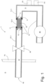
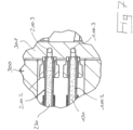
- the gas sampling probe shown is denoted by the reference numeral 1 in its entirety.
- the gas sampling probe 1 comprises a gas line 10, an adsorption material 20 and a valve 30.
- the gas line 10 comprises the sections 10.1, 10.2 and 10.3, which are fluidically connected to one another.
- the section 10.1 of the gas line 10 is a cylindrical tube made of a temperature and made of corrosion-resistant steel. Furthermore, this section 10.1 of the gas line 10 is designed to be placed in a gas.
- Section 10.1 is followed by a section 10.2 of the gas line, which is designed as a glass tube from laboratory glassware.
- the section 10.2 is plugged into the section 10.1 of the gas line 10, a gas-tightness of this plug-in connection being produced via an O-ring 11 made of rubber.
- an adsorption material 20 in the form of charcoal grit is arranged in section 10.2 in order to prevent the adsorption material 20 from trickling out of the glass tube 10.2, the lateral openings 12, 13 of the glass tube 10.2 are narrowed.
- Section 10.2 is followed by a section 10.3 of the gas line 10, which consists of an angled metal tube.
- the glass tube 10.2 is plugged into section 10.3 in accordance with the connection with section 10.1, and this plug-in connection is in turn sealed with an O-ring 14 made of rubber.
- section 10.2 is arranged in gas line 10 so that it can be removed. Furthermore, this section 10.2 can again be very easily inserted into the gas line by means of the plug-in connection.
- the sections 10.1, 10.2, 10.3 of the gas line 10 form a gas channel 15 through which a gas can flow.
- the section 10.1 of the gas line 10 comprises a gas inlet 16 in the form of an end opening at its end opposite the end at which the section 10.2 is inserted into the section 10.1 of the gas line 10.
- a gas can be introduced into the gas channel 15 through the gas inlet 16 .
- the valve 30 is arranged on section 10 .
- the valve 30 is designed as a needle valve which is electromagnetically responsive.
- the gas channel 15 is connected to a gas pump 40 downstream of the adsorption material 20 via the section 10.3 of the gas line 10.
- the gas sampling probe 1 has a pressure measuring device 50, by means of which the gas pressure in the gas channel 15 can be measured.
- the gas pressure in the section 10 . 3 of the gas line 10 arranged downstream of the adsorption material 20 can be measured by the pressure measuring device 15 .
- the gas sampling probe 1 includes a flow measuring device 60, by means of which the gas flow in the gas channel 15 can be measured.
- the gas flow in the section 10 . 3 of the gas line 10 arranged downstream of the adsorption material 20 can be measured by the flow measuring device 15 .
- the gas sampling probe 1 is arranged on a wall 70 of a gas container in the form of a combustion gas line (not shown).
- the wall 70 delimits a gas G.
- the section 10.1 of the gas line 10 is designed to be arranged in the gas G because it is made of temperature-resistant and corrosion-resistant steel.
- the gas sampling probe 10 is attached to the wall 70 in such a way that the section 10.1 of the gas line 10, on which the gas inlet 60 is arranged, is guided through the wall 70 and is partly arranged in the gas G.
- the gas sampling probe 1 is attached to the wall 70 in such a way that the remaining components of the gas sampling probe 1 are arranged outside of the gas G or outside of the gas container.
- the gas channel 15 is subjected to negative pressure using the gas pump 40 .
- a proportion of gas is sucked through the gas inlet 16 into the gas channel 15 in the gas line 10 .
- This gas sample first flows through the gas channel 15 in section 10.1, then through one open end of section 10.2 into section 10.2 and into this section 10.2 through the adsorption material 20 arranged in this section 10.2.
- the gas then flows through the opposite end 13 of the Section 10.2 back out of this section 10.2 into the section of the gas channel 15 which is formed in section 10.3 of the gas line 10.
- the gas that has flowed through the gas channel 15 is released to the environment. While the gas is passed through the gas channel 15 , the gas pressure and the gas flow rate in the gas channel 15 are continuously measured by the pressure measuring device 50 and the flow measuring device 60 .
- the adsorption material 20 adsorbs substances of the gas.
- adsorption material 20 adsorbs any mercury in the gas.
- the pump 40 is switched off, the gas channel 15 is closed by means of the valve 30 and then the section 10.2 of the gas line 10 in the form of the glass tube is removed from the gas line 10. Then, the amount of mercury adsorbed by the adsorption material 20 is quantitatively determined. Furthermore, the amount of gas that has flowed through the gas channel 15 is determined by means of the measured gas pressure and Gas flow determined. The concentration of mercury in the gas G can be determined using these measured values.
- the gas channel 15 is closed by means of the valve 30 and then the gas channel 15 downstream of the valve 30 is subjected to negative pressure by means of the pump 40. At the same time, the gas pressure in the gas channel 15 downstream of the valve 30 is measured. This makes it possible to determine whether the gas line 10 is gas-tight in this section and it is thereby ensured that the entire quantity of gas that is conducted through the gas channel 15 flows through the adsorption material 20 .
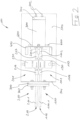
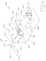
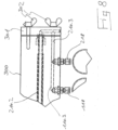
- a device 100 which comprises two gas sampling probes 110, 210.
- the two gas sampling probes 110, 210 are constructed essentially identically and are arranged parallel to one another in the device 100.
- This redundant structure of two gas sampling probes 110, 210 serves to compare the measurement results obtained by the respective gas sampling probes 110, 210 with one another and thereby to be able to estimate their informative value.
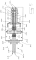
- the gas sampling probe 101 includes a gas line 110, which includes three sections 110.1, 110.2, 110.3.
- Section 110.1 is designed as a cylindrical tube made of temperature-resistant and corrosion-resistant steel.
- Section 110.2 is designed as a glass tube made from laboratory glass.
- the section 110.3 is designed as a multiply angled metal tube, which runs partially in the cover 301 of a cover 300 explained in more detail below.
- An adsorption material 120 in the form of carbon grit is arranged in the glass tube 110.2.
- a needle valve 130 is arranged between section 110.1 of gas line 110 and section 110.2 of gas line 110.
- the section 110.1 is inserted into a connecting means 116 which is fluidically coupled to the needle valve 130.
- the section 110.1 is sealed against the connecting means 116 by means of rubber O-rings.
- the section 110.2 is plugged into a connecting means 117, which is also fluidically coupled to the needle valve 130.
- the section 110.2 is correspondingly sealed against the connecting means 117 by means of O-rings 111.
- the glass tube 110.2 is largely covered by a cover 300.
- the casing 300 is designed as an essentially tubular body made of metal and can be closed by a cover 301 on one longitudinal side.
- the cover 300 On the side opposite the cover 301, the cover 300 is fastened to a holding plate 400, which in turn is fastened to a metal plate 500.
- Three resistance heating elements 600 are arranged on the casing 300, through which the interior space I enclosed by the cover 300 can be heated. As a result, the section 110.2 of the gas line 110 that is largely covered by the cover 300 and in which the adsorption material 120 is arranged can be heated by the resistance heating elements 600.
- the end of the section 110.2 opposite the end of this section 110.2 that is inserted in the connection means 117 is coupled to the section 110.3 of the gas pipe 110.
- the connection to this section 110.3 of the gas line is formed in the cover 301 of the casing 300, in which the connection piece to this section 110.3 of the gas line 110 is arranged.
- the cover 301 is screwed to the casing 300 by thumbscrews 302 . In the screwed state of the cover 301, the section 110.2 is fluidically connected to the section 110.3 of the gas line 110 via the connection formed in the cover 301.
- the gas sampling probe 110 also includes a fastening means 700 for fastening the gas sampling probe 101 to a wall of a gas container.
- This fastening means 700 is designed in the form of a flange plate which is screwed to an angled section 501 of the metal sheet 500 .
- the section 110.1 of the gas line 110 is guided through this flange plate 700.
- section 110.1 At the end of section 110.1 that is opposite the end of section 110.1 at which section 110.1 is inserted into connecting means 116, section 110.1 has a gas inlet 116.
- the gas inlet 116 opens into the gas channel 115 which is formed in the gas line 110 .
- Sections 110.1, 110.2, 110.3 of the gas line 110 are fluidically connected to one another in such a way that they form the gas channel 115 overall.
- the gas channel 1101 between the gas inlet 116 and the adsorption material 120, which is arranged in section 110.2 of the gas line 110, can be shut off by the valve 130.
- the gas sampling probe 201 is constructed accordingly and includes a gas line 210 with the three sections 210.1, 210.2, 210.3.
- the section 210.1 is coupled to the valve 230 via a connecting means 216 and the section 210.2 is also coupled to the valve 230 via the connecting means 217.
- the casing 300 also encloses the section 210.2 of the gas line 210 which is designed as a glass tube and in which the adsorption material 220 is arranged.
- the section 210.1 is guided accordingly through the flange sheet 701 and has a gas inlet 216 into the gas channel 215 formed in the gas line 210 at its free end.
- the flange sheet 700 can be arranged on a flange sheet 701, which is arranged on the wall of a gas tank, to form a flange connection of the flange sheets 700, 701.
- the sections 110.1, 210.1 of the gas lines 110, 210 of the gas sampling probes 101, 201, on which the respective gas inlet 116, 216 is arranged are arranged in the gas that is enclosed by the wall of the gas tank .
- the other components of the gas sampling probes 101, 201 are arranged outside of the gas tank.
- gas pumps can be connected to the sections 110.3, 210.3 of the gas lines 110, 210 in order to be able to conduct gas through the gas inlets 116, 216 into the gas lines 110, 210 and through the respective gas channels 115, 215.
- sections 110.3, 210.3 have screw connections 118, 218, to each of which a suction line with a gas pump can be connected.
- the sections 110.2, 210.2 of the gas lines 110, 210 designed as glass tubes are designed to be removable in the respective gas lines 110, 210.
- the cover 301 is detached from the casing 300 by loosening the wing screws 302.
- the glass tubes 110.2, 210.2 can then be pulled out of the connecting means 117, 217.
- the adsorption material 120, 220 arranged in the glass tubes 110.2, 210.2 can then be analyzed.
Description
Die Erfindung betrifft eine Gasentnahmesonde, einen Gasbehälter mit einer solchen daran befestigten Gasentnahmesonde sowie ein Verfahren zur Entnahme einer Gasprobe aus einem Gas eines Gasbehälters mittels einer solchen Gasentnahmesonde.The invention relates to a gas sampling probe, a gas container with such a gas sampling probe attached thereto and a method for taking a gas sample from a gas in a gas container by means of such a gas sampling probe.
Gasentnahmesonden dienen zur Entnahme einer Gasprobe aus einem Gas, das insbesondere in einem Gasbehälter vorhanden sein kann. Die entnommene Gasprobe kann anschließend einer Analyse zugeführt werden. Beispielsweise kann die Analyse dazu dienen, bestimmte Substanzen im Gas qualitativ und/oder quantitativ zu bestimmen. Bei diesen Substanzen kann es sich beispielsweise um umwelt- oder gesundheitsgefährdende Substanzen handeln.Gas sampling probes are used to take a gas sample from a gas that can be present in a gas container in particular. The gas sample taken can then be analyzed. For example, the analysis can serve to determine certain substances in the gas qualitatively and/or quantitatively. These substances can, for example, be substances that are hazardous to the environment or to health.
Gasentnahmesonden können eine Gasleitung aufweisen, in der ein Gaskanal ausgebildet ist, durch den ein Gas strömen kann. Die Gasleitung kann einen Gaseinlass aufweisen, durch den ein Gas in den Gaskanal einleitbar ist. Zur Entnahme einer Gasprobe aus Gas mittels einer solchen Gasentnahmesonde wird die Gasleitung der Gasentnahmesonde derart in ein Gas eingeführt, dass Gas durch den Gaseinlass in den Gaskanal einströmen kann. Das in den Gaskanal einströmende Gas dient als Gasprobe, das anschließend wie vorstehend analysiert werden kann.Gas sampling probes can have a gas line in which a gas channel is formed through which a gas can flow. The gas line can have a gas inlet through which a gas can be introduced into the gas channel. To take a gas sample from gas using such a gas sampling probe, the gas line of the gas sampling probe is inserted into a gas in such a way that gas can flow through the gas inlet into the gas channel. The gas flowing into the gas channel serves as a gas sample, which can then be analyzed as above.
Es ist bekannt, z.B. von
Zur Analyse der vom Adsorptionsmaterial adsorbierten Substanzen wird die Gasleitung der Gasentnahmesonde aus dem Gas herausgezogen und das Adsorptionsmaterial aus dem Gaskanal im Bereich des Gaseinlasses entnommen. Das entnommene Adsorptionsmaterial kann schließlich hinsichtlich etwaig adsorbierter Substanzen analysiert werden.To analyze the substances adsorbed by the adsorption material, the gas line of the gas sampling probe is pulled out of the gas and the adsorption material is removed from the gas channel in the area of the gas inlet. The removed adsorption material can finally be analyzed with regard to any adsorbed substances.
Bei dieser Technologie ist es wichtig, dass tatsächlich das gesamte durch den Gaseinlass in den Gaskanal eingeleitete Gas durch das Adsorptionsmaterial strömt. Dies ist insbesondere dann der Fall, wenn der einzige Gaszutritt in den Gaskanal durch den Gaseinlass möglich ist. Um dies zu überprüfen, wird an gattungsgemäßen Gasentnahmesonden regelmäßig eine Dichtigkeitsprüfung durchgeführt. Dabei wird die Gasleitung der Gasentnahmesonde aus dem zu untersuchenden Gas herausgenommen und der Gaseinlass durch einen Stopfen verschlossen. Anschließend wird der Gaskanal durch eine Gaspumpe mit Unterdruck beaufschlagt. Durch Messung des dabei im Gaskanal entstehenden Unterdrucks ist bestimmbar, ob der Gaseinlass den einzig möglichen Gaszutritt in den Gaskanal bildet.With this technology it is important that actually all of the gas introduced into the gas channel through the gas inlet flows through the adsorption material. This is the case in particular when the only gas entry into the gas channel is possible through the gas inlet. To check this, generic gas sampling probes regularly carry out a leak test. The gas line of the gas sampling probe is removed from the gas to be examined and the gas inlet is sealed with a plug. The gas channel is then subjected to negative pressure by a gas pump. By measuring the negative pressure that occurs in the gas channel, it can be determined whether the gas inlet forms the only possible gas inlet into the gas channel.
Grundsätzlich haben sich derart ausgebildete Gasentnahmesonden zur Entnahme von Gasproben aus einem Gas bewehrt. Nachteilig ist jedoch, dass die Gasleitung stets aus dem zu analysierenden Gas entfernt werden muss, um das Adsorptionsmaterial aus der Gasleitung entnehmen und hinsichtlich darin etwaig adsorbierter Substanzen analysieren zu können. Ferner ist nachteilig, dass die Gasleitung auch zur Durchführung der Dichtigkeitsprüfung stets aus dem zu analysierenden Gas entfernt werden muss.In principle, gas sampling probes designed in this way have proven themselves for taking gas samples from a gas. The disadvantage, however, is that the gas line must always be removed from the gas to be analyzed in order to be able to remove the adsorption material from the gas line and analyze it with regard to any substances adsorbed therein. Furthermore, it is disadvantageous that the gas line always has to be removed from the gas to be analyzed to carry out the leak test.
Der Erfindung liegt die Aufgabe zugrunde, eine Gasentnahmesonde zur Verfügung zu stellen, bei der die Gasleitung nicht aus einem zu analysierenden Gas entfernt werden muss, um im Gaskanal der Gasleitung angeordnetes Adsorptionsmaterial zu dessen Analyse aus der Gasleitung entnehmen zu können. Eine weitere Aufgabe der Erfindung besteht darin, eine Gasentnahmesonde zur Verfügung zu stellen, bei der die Gasleitung nicht aus einem zu analysierenden Gas entnommen werden muss, um eine Dichtigkeitsprüfung des Gaskanals der Gasleitung durchführen zu können.The object of the invention is to provide a gas sampling probe in which the gas line does not have to be removed from a gas to be analyzed in order to be able to remove adsorption material arranged in the gas channel of the gas line from the gas line for its analysis. A further object of the invention is to provide a gas sampling probe in which the gas line does not have to be removed from a gas to be analyzed in order to be able to carry out a leak test of the gas channel of the gas line.
Eine weitere Aufgabe der Erfindung besteht darin, einen Gasbehälter mit einer solchen daran befestigten Gasentnahmesonde zur Verfügung zu stellen.A further object of the invention is to provide a gas container with such a gas sampling probe attached thereto.
Eine weitere Aufgabe der Erfindung besteht darin, ein Verfahren zur Entnahme einer Gasprobe mit einer solchen Gasentnahmesonde zur Verfügung zu stellen.Another object of the invention is to provide a method for taking a gas sample with such a gas sampling probe.
Zur Lösung der Aufgabe wird erfindungsgemäß zur Verfügung gestellt eine Gasentnahmesonde, die in Anspruch 1 definiert ist.In order to achieve the object, a gas sampling probe, which is defined in claim 1, is made available according to the invention.
Eine Grundidee der Erfindung besteht darin, das Adsorptionsmaterial stromabwärts des Gaseinlasses in dem Gaskanal anzuordnen und gleichzeitig ein Ventil vorzusehen, durch das der Gaskanal zwischen dem Gaseinlass und dem Adsorptionsmaterial absperrbar ist. Dies ermöglicht es zum einen, das Adsorptionsmaterial aus dem Gaskanal zu entnehmen, ohne die Gasleitung zuvor aus dem zu analysierenden Gas entfernen zu müssen. Gleichzeitig ermöglicht dies, eine Dichtigkeitsprüfung des Gaskanals durchzuführen, ohne die Gasleitung zuvor aus dem analysierenden Gas entfernen zu müssen. Vielmehr kann zur Entnahme des Adsorptionsmaterials aus dem Gaskanal der Abschnitt der Gasleitung, der in einem zu analysierenden Gas angeordnet ist, in diesem Gas verbleiben, während das stromabwärts des Gaseinlasses in dem Gaskanal angeordnete Adsorptionsmaterial aus dem Gaskanal entnommen werden kann. Dabei kann insbesondere vorgesehen sein, dass das Ventil den Gaskanal zwischen dem Gaseinlass und dem Adsorptionsmaterial absperrt, während das Adsorptionsmaterial aus dem Gaskanal entnommen wird.A basic idea of the invention consists in arranging the adsorption material in the gas channel downstream of the gas inlet and at the same time providing a valve through which the gas channel between the gas inlet and the adsorption material can be shut off. On the one hand, this makes it possible to remove the adsorption material from the gas channel without first having to remove the gas line from the gas to be analyzed. At the same time, this makes it possible to carry out a leak test of the gas channel without having to first remove the gas line from the gas to be analyzed. Rather, to remove the adsorption material from the gas channel, the section of the gas line that is arranged in a gas to be analyzed can remain in this gas, while the adsorption material arranged downstream of the gas inlet in the gas channel can be removed from the gas channel. It can be provided in particular that the valve closes the gas channel between the gas inlet and the adsorption material shuts off while the adsorption material is removed from the gas channel.
Ferner kann die Dichtigkeitsprüfung ganz einfach durchgeführt werden, indem das Ventil den Gaskanal zwischen dem Gaseinlass und dem Adsorptionsmaterial absperrt und anschließend der Unterdruck im Gaskanal stromabwärts des Ventils bestimmt wird. Hierzu kann bei abgesperrtem Ventil der stromabwärts des Ventils liegende Abschnitt des Gaskanals durch eine Gaspumpe mit Unterdruck beaufschlagt werden und gleichzeitig der Unterdruck in diesem Abschnitt der Gasleitung bestimmt werden.Furthermore, the leak test can be carried out very easily by the valve shutting off the gas channel between the gas inlet and the adsorption material and then the negative pressure in the gas channel is determined downstream of the valve. For this purpose, with the valve shut off, the section of the gas channel located downstream of the valve can be subjected to negative pressure by a gas pump and the negative pressure in this section of the gas line can be determined at the same time.
Die Gasleitung kann grundsätzlich in Form einer beliebigen aus dem Stand der Technik bekannten Gasleitung vorliegen, also einer Leitung, in der ein Gaskanal ausgebildet ist, durch den ein Gas strömen beziehungsweise geleitet werden kann. Insoweit kann die Gasleitung beispielsweise aus einem oder mehreren Rohren oder Schläuchen zur Leitung eines Gases ausgebildet sein. Bevorzugt ist die Gasleitung derart ausgebildet dass durch diese ein Abgas, insbesondere ein Verbrennungsgas leitbar ist. Insoweit ist die Gasleitung bevorzugt derart ausgebildet, dass durch diese ein heißes Gas und/oder ein korrosives Gas leitbar ist. Insoweit ist bevorzugt vorgesehen, dass die Gasleitung aus einem hitzebeständigen und/oder nicht-korrosiven Material besteht, insbesondere aus Metall (bevorzugt aus Stahl oder einer Stahllegierung) Glas oder Keramik. Besonders bevorzugt ist die Gasleitung aus Metall und/oder Glas ausgebildet.The gas line can in principle be in the form of any gas line known from the prior art, ie a line in which a gas channel is formed through which a gas can flow or be conducted. In this respect, the gas line can be formed, for example, from one or more tubes or hoses for conducting a gas. The gas line is preferably designed in such a way that an exhaust gas, in particular a combustion gas, can be routed through it. In this respect, the gas line is preferably designed in such a way that a hot gas and/or a corrosive gas can be conducted through it. In this regard, it is preferably provided that the gas line consists of a heat-resistant and/or non-corrosive material, in particular metal (preferably steel or a steel alloy), glass or ceramics. The gas line is particularly preferably made of metal and/or glass.
Der in der Gasleitung ausgebildete Gaskanal kann grundsätzlich einen beliebigen Querschnitt aufweisen. Bevorzugt weist der Gaskanal einen kreisförmigen Querschnitt auf. Dies hat den Vorteil, dass Gas sehr gleichförmig, insbesondere laminar durch den Gaskanal strömen kann.In principle, the gas channel formed in the gas line can have any desired cross section. The gas channel preferably has a circular cross section. This has the advantage that gas can flow very uniformly, in particular in a laminar manner, through the gas channel.
Die Gasleitung weist einen Gaseinlass auf, der derart ausgebildet ist, dass durch diesen Gas in den Gaskanal einleitbar beziehungsweise einströmbar ist. Bevorzugt ist der Gaseinlass als endseitige Öffnung der Gasleitung ausgebildet.The gas line has a gas inlet which is designed in such a way that gas can be introduced or flow into the gas channel through it. The gas inlet is preferably designed as an opening at the end of the gas line.
Ein durch den Gaseinlass in den Gaskanal eingeleitetes Gas ist anschließend durch den Gaskanal strömbar. "Stromabwärts" im Sinne der vorliegenden Erfindung bedeutet demnach in Strömungsrichtung eines durch den Gaseinlass in den Gaskanal eingeleiteten und durch den Gaskanal strömenden Gases. Insoweit bezeichnet beispielsweise der Ausdruck "stromabwärts des Gaseinlasses" in Strömungsrichtung des Gases hinter dem Gaseinlass.A gas introduced into the gas channel through the gas inlet can then flow through the gas channel. “Downstream” in the sense of the present invention therefore means in the direction of flow of a gas introduced through the gas inlet into the gas channel and flowing through the gas channel. In this respect, for example, the expression "downstream of the gas inlet" designates behind the gas inlet in the flow direction of the gas.
Der Gaseinlass ist in einem Abschnitt der Gasleitung ausgebildet, der zur Anordnung in einem Gas ausgebildet ist. Bei diesem Gas handelt es sich um ein Gas, von dem durch die erfindungsgemäße Gasentnahmesonde eine Probe entnommen werden kann. Indem der Gaseinlass an einem solchen Abschnitt der Gasleitung ausgebildet ist, der zur Anordnung in einem Gas ausgebildet ist, kann dieser Abschnitt der Gasleitung in einem Gas angeordnet und Gas aus diesem Gas über den Gaseinlass in den Gaskanal der Gasleitung einströmen. Dieser Abschnitt der Gasleitung ist bevorzugt derart ausgebildet, dass dieser in einem Abgas, insbesondere in einem Verbrennungsgas anordenbar ist. Insoweit kann dieser Abschnitt der Gasleitung bevorzugt derart ausgebildet sein, dass dieser in einem heißen Gas und/oder in einem korrosiven Gas anordenbar ist. Insoweit kann dieser Abschnitt der Gasleitung bevorzugt aus einem hitzebeständigen und/oder nicht-korrosiven Material bestehen, insbesondere aus einem Metall (insbesondere einem Stahl oder einer Stahllegierung).The gas inlet is formed in a portion of the gas line that is formed for placement in a gas. This gas is a gas from which a sample can be taken by the gas sampling probe according to the invention. Since the gas inlet is formed on a section of the gas line that is designed to be arranged in a gas, this section of the gas line can be arranged in a gas and gas from this gas can flow into the gas channel of the gas line via the gas inlet. This section of the gas line is preferably designed in such a way that it can be arranged in an exhaust gas, in particular in a combustion gas. In this respect, this section of the gas line can preferably be designed in such a way that it can be arranged in a hot gas and/or in a corrosive gas. In this respect, this section of the gas line can preferably consist of a heat-resistant and/or non-corrosive material, in particular made of a metal (in particular a steel or a steel alloy).
Stromabwärts des Gaseinlasses, also in Strömungsrichtung des durch den Gaseinlass in den Gaskanal strömenden Gases hinter dem Gaseinlass, ist ein Adsorptionsmaterial in dem Gaskanal der Gasleitung angeordnet. Das Adsorptionsmaterial ist zur Adsorption wenigstens einer Substanz eines Gases ausgebildet, insbesondere zur Absorption etwaiger umwelt- oder gesundheitsgefährdender Substanzen in dem durch den Gaskanal strömbaren Gas. Bei diesen Substanzen kann es sich beispielsweise um eine oder mehrere der folgenden Substanzen handeln: wenigstens ein Schwermetall (insbesondere Quecksilber), Dioxin oder Furane. Insbesondere kann das Adsorptionsmaterial zur Adsorption von Quecksilber ausgebildet sein.An adsorption material is arranged in the gas channel of the gas line downstream of the gas inlet, ie behind the gas inlet in the flow direction of the gas flowing through the gas inlet into the gas channel. The adsorption material is designed to adsorb at least one substance of a gas, in particular to absorb any substances that are hazardous to the environment or health in the gas that can flow through the gas channel. These substances can be, for example, one or more of the following substances: at least one heavy metal (especially mercury), dioxin or furans. In particular, the adsorption material can be designed for the adsorption of mercury.
Nach einer besonders bevorzugten Ausführungsform ist das Adsorptionsmaterial als Schüttgut ausgebildet, also als schüttbeziehungsweise rieselfähiges Gut, insbesondere in Form eines Korngemenges. Insoweit kann das Adsorptionsmaterial beispielsweise in Form von Körnern, insbesondere beispielsweise in Form von Gries vorliegen. Insbesondere kann das Adsorptionsmaterial als durch ein Gas durchströmbares Schüttgut ausgebildet sein. Insoweit besitzt das als Schüttgut ausgebildete Adsorptionsmaterial eine solche Korngröße, dass dieses durch Gas durchströmbar ist.According to a particularly preferred embodiment, the adsorption material is designed as bulk material, ie as pourable or free-flowing material, in particular in the form of a grain mixture. In this respect, the adsorption material can be present, for example, in the form of grains, in particular, for example, in the form of grit. In particular, the adsorption material can be in the form of bulk material through which a gas can flow. In this respect, the adsorption material designed as bulk material has such a particle size that gas can flow through it.
Als Adsorptionsmaterial kann grundsätzlich eine beliebige Substanz vorliegen, durch die eine oder mehrere Substanzen, hinsichtlich derer die durch die Gasentnahmesonde zu entnehmende Gasprobe analysiert werden soll, adsorbierbar sind. Insoweit kann für die jeweils zu analysierende Substanz ein jeweils geeignetes Adsorbat verwendet werden. Nach einer besonders bevorzugten Ausführungsform liegt als Adsorptionsmaterial Kohle vor. Der besondere Vorteil von Kohle als Adsorptionsmaterial liegt insbesondere darin, dass durch Kohle sehr zahlreiche Substanzen adsorbierbar sind, insbesondere beispielsweise auch Quecksilber. Insbesondere kann das Adsorptionsmaterial insoweit als Kohle vorliegen, die insbesondere wie vorstehend als Schüttgut ausgebildet sein kann.In principle, the adsorption material can be any substance by which one or more substances for which the gas sample to be taken by the gas sampling probe is to be analyzed can be adsorbed. In this respect, a suitable adsorbate can be used for the substance to be analyzed in each case become. According to a particularly preferred embodiment, the adsorption material is carbon. The particular advantage of charcoal as an adsorption material lies in the fact that a great number of substances can be adsorbed by charcoal, in particular mercury, for example. In particular, the adsorption material can be in the form of carbon, which in particular can be in the form of bulk material, as described above.
Bevorzugt ist der Abschnitt der Gasleitung, in dem das Adsorptionsmaterial in dem Gaskanal der Gasleitung angeordnet ist, vollständig mit dem Adsorptionsmaterial verfüllt. Mit anderen Worten ist der Gaskanal beziehungsweise der Strömungsquerschnitt des Gaskanals in dem Abschnitt der Gasleitung, in dem das Adsorptionsmaterial angeordnet ist, vollständig mit dem Adsorptionsmaterial verfüllt. Dies hat den besonderen Vorteil, dass hierdurch gewährleistet ist, dass das gesamte durch den Gaskanal strömende Gas das Adsorptionsmaterial durchströmt beziehungsweise eine Form von Schüttgut ausgebildetes Adsorptionsmaterial durchströmt, so dass die vom Adsorptionsmaterial adsorbierbaren Substanzen des Gases sehr gut vom Adsorptionsmaterial adsorbiert werden können.The section of the gas line in which the adsorption material is arranged in the gas channel of the gas line is preferably completely filled with the adsorption material. In other words, the gas channel or the flow cross section of the gas channel is completely filled with the adsorption material in the section of the gas line in which the adsorption material is arranged. This has the particular advantage that it ensures that all of the gas flowing through the gas channel flows through the adsorption material or flows through an adsorption material in the form of bulk material, so that the substances in the gas that can be adsorbed by the adsorption material can be adsorbed very well by the adsorption material.
Nach einer besonders bevorzugten Ausführungsform ist das Adsorptionsmaterial in einem Abschnitt der Gasleitung angeordnet, der entnehmbar in der Gasleitung angeordnet ist. Dieser Abschnitt der Gasleitung ist demnach aus der Gasleitung lösbar beziehungsweise von dem diesem Abschnitt benachbarten Abschnitten der Gasleitung trennbar und hierdurch aus der Gasleitung entnehmbar. Dies hat den besonderen Vorteil, dass das Adsorptionsmaterial zu dessen anschließender Analyse der daran adsorbierten Substanzen besonders leicht von der Gassonde entnehmbar und einer anschließenden Analyse zuführbar ist. Nach einer bevorzugten Fortbildung dieses Erfindungsgedankens ist dieser von der Gasleitung entnehmbare Abschnitt auch wieder in die Gasleitung einsetzbar. Dies hat den besonderen Vorteil, dass neues Adsorptionsmaterial, das noch keine zu analysierenden Substanzen adsorbiert hat, sehr einfach wieder in die Gasleitung einsetzbar ist und die Gasentnahmesonde daher, nachdem zu analysierendes Adsorptionsmaterial aus dieser entnommen worden ist, schnell wieder einsatzfähig ist, um eine weitere Gasprobe entnehmen zu können.According to a particularly preferred embodiment, the adsorption material is arranged in a section of the gas line which is arranged removably in the gas line. Accordingly, this section of the gas line can be detached from the gas line or can be separated from the sections of the gas line adjacent to this section and can thereby be removed from the gas line. This has the particular advantage that the adsorption material can be removed from the gas probe particularly easily for subsequent analysis of the substances adsorbed on it and can be fed to a subsequent analysis. After a In a preferred development of this inventive concept, this section that can be removed from the gas line can also be reinserted into the gas line. This has the particular advantage that new adsorption material that has not yet adsorbed any substances to be analyzed can be reinserted very easily into the gas line and the gas sampling probe is therefore quickly ready for use again after the adsorption material to be analyzed has been removed from it, in order to to take a gas sample.
Das Adsorptionsmaterial ist in einem Abschnitt der Gasleitung angeordnet, der aus Glas ausgebildet ist. Dies hat insbesondere den Vorteil, dass eine etwaige unerwünschte Reaktion zwischen dem Adsorptionsmaterial und dem Glas ausgeschlossen ist, da Glas praktisch mit keinem Material reagiert und insoweit praktisch inerte ist. Insoweit können praktisch keine Substanzen des Glases vom Adsorptionsmaterial adsorbiert werden und eine etwaige Analyse des Adsorptionsmaterials hierdurch verfälschen. Als Glas für diesen Abschnitt kann beispielsweise Kalk-Natron-Glas verwendet werden, bevorzugt jedoch Laborglas, insbesondere Borosilikatglas.The adsorption material is arranged in a section of the gas line that is made of glass. This has the advantage, in particular, that any undesired reaction between the adsorption material and the glass is ruled out, since glass reacts with practically no material and is therefore practically inert. In this respect, practically no substances of the glass can be adsorbed by the adsorption material and thereby falsify any analysis of the adsorption material. Soda-lime glass, for example, can be used as the glass for this section, but laboratory glass, in particular borosilicate glass, is preferred.
Der aus Glas ausgebildete Abschnitt der Gasleitung, in dem das Adsorptionsmaterial angeordnet ist, kann beispielsweise als Rohr, also als Glasrohr ausgebildet sein. Über Verbindungsmittel kann das Rohr an die sich daran anschließenden Abschnitte der Gasleitung anschließbar sein. Insoweit kann auf die aus dem Stand der Technik bekannten Verbindungsmittel zur Verbindung von Rohren beziehungsweise Rohrstücken zurückgegriffen werden. Beispielsweise kann der aus Glas ausgebildete Abschnitt der Gasleitung, in dem das Adsorptionsmaterial angeordnet ist, über Verbindungsmittel in Form von Steckverbindungen oder Schraubverbindungen mit den sich daran anschließenden Abschnitten der Gasleitung verbunden sein. Um die Gasdichtigkeit im Bereich dieser Verbindungsmittel zu gewährleisten, können geeignete Dichtungen vorgesehen sein, beispielsweise Dichtungsringe, insbesondere beispielsweise O-Ringe.The section of the gas line made of glass, in which the adsorption material is arranged, can be made, for example, as a tube, ie as a glass tube. The pipe can be connected to the adjoining sections of the gas line via connecting means. In this respect, the connecting means known from the prior art for connecting pipes or pipe sections can be used. For example, the section of the gas line made of glass, in which the adsorption material is arranged, can have connecting means in the form of plug connections or screw connections with the adjoining ones Sections of the gas line to be connected. In order to ensure gas-tightness in the area of these connecting means, suitable seals can be provided, for example sealing rings, in particular for example O-rings.
Das Ventil, durch das der Gaskanal zwischen dem Gaseinlass und dem Adsorptionsmaterial absperrbar ist, kann grundsätzlich ein beliebiges Ventil nach dem Stand der Technik sein, durch den eine Gasleitung beziehungsweise ein Gaskanal in einer Gasleitung absperrbar ist. Beispielsweise kann es sich bei dem Ventil um ein Nadelventil oder einen Kugelhahn handeln. Bevorzugt handelt es sich bei dem Ventil um ein Magnetventil, also ein elektromagnetisch ansprechbares Ventil. Dies hat den Vorteil, dass das Ventil besonders einfach, insbesondere elektrisch betätigbar ist.The valve that can be used to shut off the gas channel between the gas inlet and the adsorption material can basically be any valve according to the prior art that can be used to shut off a gas line or a gas channel in a gas line. For example, the valve can be a needle valve or a ball valve. The valve is preferably a solenoid valve, ie an electromagnetically addressable valve. This has the advantage that the valve can be actuated particularly easily, in particular electrically.
Nach einer bevorzugten Ausführungsform umfasst die Gasentnahmesonde ein Befestigungsmittel zur Befestigung der Gasentnahmesonde an einer Wand eines Gasbehälters. Hierdurch ist die Gasentnahmesonde besonders einfach an einer Wand eines Gasbehälters befestigbar.According to a preferred embodiment, the gas sampling probe comprises a fastening means for fastening the gas sampling probe to a wall of a gas container. As a result, the gas sampling probe can be attached to a wall of a gas container in a particularly simple manner.
Bei einem Gasbehälter im Sinne der Erfindung kann es sich grundsätzlich um eine beliebige Vorrichtung handeln, durch die ein Gas speicherbar oder leitbar ist, insbesondere ein Abgas, insbesondere ein Verbrennungsgas speicherbar oder leitbar ist. Die Wand des Gasbehälters, an der die Gasentnahmesonde über das Befestigungsmittel befestigbar ist, begrenzt ein entsprechendes Gas, also einen Innenraum zur Aufnahme des durch den Gasbehälter speicherbaren oder leitbaren Gases. Insbesondere kann der Gasbehälter in Form einer Abgasleitung, insbesondere in Form einer Verbrennungsgasleitung vorliegen. Insoweit kann die Gasentnahmesonde insbesondere ein Befestigungsmittel zur Befestigung der Gasentnahmesonde an einer Wand einer Abgasleitung, insbesondere an einer Wand einer Verbrennungsgasleitung umfassen.A gas tank within the meaning of the invention can in principle be any device through which a gas can be stored or conducted, in particular an exhaust gas, in particular a combustion gas can be stored or conducted. The wall of the gas container, to which the gas sampling probe can be fastened via the fastening means, delimits a corresponding gas, ie an interior space for receiving the gas that can be stored or conducted by the gas container. In particular, the gas tank can be in the form of an exhaust gas line, in particular in the form of a combustion gas line. In that regard, the gas sampling probe in particular a fastener for Attachment of the gas sampling probe to a wall of an exhaust pipe, in particular to a wall of a combustion gas pipe.
Nach einer Fortbildung dieses Erfindungsgedankens kann das Befestigungsmittel derart ausgebildet sein, dass die Gasentnahmesonde über das Befestigungsmittel derart an der Wand befestigbar ist, dass der Abschnitt der Gasleitung, an dem der Gaseinlass angeordnet ist, innerhalb des Gasbehälters angeordnet ist. Dies hat den besonderen Vorteil, dass die Gasentnahmesonde über das Befestigungsmittel besonders einfach derart an der Wand des Gasbehälters befestigbar ist, dass der Gaseinlass innerhalb des Gasbehälters angeordnet ist und somit im Gasbehälter befindliches Gas, von dem durch die Gasentnahmesonde eine Probe entnommen werden soll, ohne Weiteres über den Gaseinlass in den Gaskanal der Gasleitung der Gasentnahmesonde strömen kann und insoweit durch die Gasentnahmesonde eine Probe aus dem Gas entnommen werden kann. Nach einer bevorzugten Weiterbildung dieses Erfindungsgedankens ist das Befestigungsmittel derart ausgebildet, dass die Gasentnahmesonde derart über das Befestigungsmittel an der Wand des Gasbehälters befestigbar ist, dass der Abschnitt der Gasleitung, an dem der Gaseinlass angeordnet ist, innerhalb des Gasbehälters angeordnet ist und der Abschnitt der Gasleitung, in dem das Adsorptionsmaterial angeordnet ist, außerhalb des Gasbehälters angeordnet ist. Dies hat den besonderen Vorteil, dass das Adsorptionsmaterial besonders einfach aus der Gasleitung entnommen werden kann, insbesondere auch, ohne die Gasleitung zuvor von dem Gasbehälter entnehmen zu müssen. Besonders einfach ist die Entnahme des Adsorptionsmaterials, wenn die Gasentnahmesonde, wie zuvor ausgeführt, derart ausgebildet ist, dass das Adsorptionsmaterial in einem Abschnitt der Gasleitung angeordnet ist, der entnehmbar in der Gasleitung angeordnet ist. Nach einer weiteren Fortbildung dieses Erfindungsgedankens kann das Befestigungsmittel der Gasentnahmesonde derart ausgebildet sein, dass die Gasentnahmesonde derart über das Befestigungsmittel an der Wand befestigbar ist, dass das Ventil außerhalb des Gasbehälters angeordnet ist. Insbesondere hat dies den Vorteil, dass das Ventil in diesem Fall durch etwaige heiße oder aggressive Gase im Gasbehälter nicht angegriffen wird und die Gasentnahmesonde daher besonders wartungsarm betrieben werden kann. Ein weiterer Vorteil besteht darin, dass das Ventil besonders einfach bedienbar ist.According to a further development of this inventive idea, the fastening means can be designed in such a way that the gas sampling probe can be fastened to the wall via the fastening means in such a way that the section of the gas line on which the gas inlet is arranged is arranged inside the gas tank. This has the particular advantage that the gas sampling probe can be attached particularly easily to the wall of the gas container via the fastening means in such a way that the gas inlet is arranged inside the gas container and the gas in the gas container, from which a sample is to be taken by the gas sampling probe, can be removed without Further can flow via the gas inlet into the gas channel of the gas line of the gas sampling probe and to this extent a sample can be taken from the gas through the gas sampling probe. According to a preferred development of this idea of the invention, the fastening means is designed in such a way that the gas sampling probe can be fastened to the wall of the gas tank via the fastening means in such a way that the section of the gas line on which the gas inlet is arranged is arranged inside the gas tank and the section of the gas line , in which the adsorption material is arranged, is arranged outside the gas container. This has the particular advantage that the adsorption material can be removed from the gas line particularly easily, in particular without having to remove the gas line from the gas container beforehand. The extraction of the adsorption material is particularly simple if the gas extraction probe, as explained above, is designed in such a way that the adsorption material is arranged in a section of the gas line that is arranged in the gas line in a removable manner. After further training this According to the idea of the invention, the fastening means of the gas sampling probe can be designed in such a way that the gas sampling probe can be fastened to the wall via the fastening means in such a way that the valve is arranged outside of the gas container. In particular, this has the advantage that in this case the valve is not attacked by any hot or aggressive gases in the gas container and the gas sampling probe can therefore be operated with particularly little maintenance. Another advantage is that the valve is particularly easy to use.
Nach einer Ausführungsform ist vorgesehen, dass die Gasentnahmesonde eine Gaspumpe umfasst, durch die der Gaskanal mit Unterdruck beaufschlagbar ist, wobei der Gaskanal bevorzugt stromabwärts des Adsorptionsmaterials an die Gaspumpe angeschlossen ist. Mit anderen Worten führt der Gaskanal stromabwärts des Adsorptionsmaterials zu einer Gaspumpe, durch die der Gaskanal mit Unterdruck beaufschlagbar ist.According to one embodiment, it is provided that the gas sampling probe comprises a gas pump, by means of which the gas channel can be subjected to negative pressure, the gas channel preferably being connected to the gas pump downstream of the adsorption material. In other words, the gas channel leads downstream of the adsorption material to a gas pump, through which the gas channel can be subjected to negative pressure.
Bei der Gaspumpe kann es sich grundsätzlich um eine beliebige Pumpe handeln, durch die Gas pumpbar und damit der Gaskanal mit Unterdruck beaufschlagbar ist. Beispielsweise kann es sich bei der Gaspumpe um eine Faltenbalgpumpe handeln.In principle, the gas pump can be any pump through which the gas can be pumped and thus the gas channel can be subjected to negative pressure. For example, the gas pump can be a bellows pump.
Nach einer Ausführungsform umfasst die Gasentnahmesonde ein Heizmittel, durch das der Abschnitt der Gasleitung, in der das Absorptionsmaterial angeordnet ist, beheizbar ist. Insofern können beispielsweise in dem Abschnitt der Gasleitung, in der das Adsorptionsmaterial angeordnet ist, Heizmittel angeordnet sein, durch die dieser Abschnitt der Gasleitung beheizbar ist. Beispielsweise kann es sich bei diesen Heizmitteln um Widerstandheizelemente handeln.According to one embodiment, the gas sampling probe comprises a heating means, by means of which the section of the gas line in which the absorption material is arranged can be heated. In this respect, for example, heating means can be arranged in the section of the gas line in which the adsorption material is arranged, by means of which this section of the gas line can be heated. For example, these heating means can be resistance heating elements.
Solche Heizmittel haben insbesondere den Vorteil, dass eine Bildung von Kondensflüssigkeit in diesem Abschnitt der Gasleitung, in der das Adsorptionsmaterial angeordnet ist, verhindert werden kann, indem dieser Abschnitt durch die Heizmittel beheizt wird. Dies hat den Vorteil, dass durch die Vermeidung von Kondensflüssigkeit im Bereich des Adsorptionsmaterials eine verschlechterte Adsorption durch das Adsorptionsmaterial auf Grund von Kondensflüssigkeit verhindert werden kann.Such heating means have the advantage, in particular, that the formation of condensed liquid in that section of the gas line in which the adsorption material is arranged can be prevented by this section being heated by the heating means. This has the advantage that by avoiding condensation liquid in the area of the adsorption material, impaired adsorption by the adsorption material due to condensation liquid can be prevented.
Nach einer Ausführungsform umfasst die Gasentnahmesonde eine Umhüllung, durch die der Abschnitt der Gasleitung, in der das Adsorptionsmaterial angeordnet ist, zumindest abschnittsweise umhüllbar ist. Beispielsweise kann es sich bei dieser Umhüllung um eine zylindrische Umhüllung handeln, beispielsweise eine Umhüllung aus Metall. Diese Umhüllung kann beispielsweise eine im wesentlichen kreiszylindrische Form aufweisen, die um den Abschnitt der Gasleitung, in der das Adsorptionsmaterial angeordnet ist, herum angeordnet ist. Nach einer Fortbildung kann der Innenraum dieser Umhüllung beheizbar sein, insbesondere durch die wie vorstehend ausgebildeten Heizmittel. Indem der Innenraum der Umhüllung beheizbar ist und im Innenraum der Umhüllung gleichzeitig der Abschnitt der Gasleitung, in dem das Adsorptionsmaterial angeordnet ist, angeordnet ist, kann dieser Abschnitt sehr effektiv beheizt werden.According to one embodiment, the gas sampling probe comprises an envelope through which the section of the gas line in which the adsorption material is arranged can be enveloped at least in sections. For example, this casing can be a cylindrical casing, for example a metal casing. This covering can, for example, have an essentially circular-cylindrical shape, which is arranged around the section of the gas line in which the adsorption material is arranged. According to a development, the interior of this envelope can be heated, in particular by the heating means designed as above. Since the interior of the casing can be heated and the section of the gas line in which the adsorption material is arranged is simultaneously arranged in the interior of the casing, this section can be heated very effectively.
Nach einer Ausführungsform ist vorgesehen, dass zumindest ein Abschnitt der Gasleitung in der Wandung einer solchen Umhüllung geführt ist. Beispielsweise kann eine Umhüllung, insbesondere beispielsweise eine zylindrische Umhüllung, einen endseitigen Deckel aufweisen, in dem ein Abschnitt der Gasleitung ausgebildet ist. Beispielsweise kann ein solcher, in einem Deckel der Umhüllung ausgebildeter Abschnitt der Gasleitung, zum Anschluss an den Abschnitt der Gasleitung ausgebildet sein, in dem das Adsorptionsmaterial angeordnet ist, insbesondere beispielsweise einen entnehmbaren Abschnitt, wie oben ausgeführt. Nach einer Ausführungsform ist ein Deckel der Umhüllung derart ausgebildet, dass er derart an der Umhüllung befestigbar ist, dass er in seiner an der Umhüllung befestigten Stellung einen Abschnitt der Gasleitung, in der das Adsorptionsmaterial angeordnet ist, und der entnehmbar in der Gasleitung angeordnet ist, in einer gesicherten Stellung in der Gasleitung hält und bei Lösung des Deckels die Entnahme dieses Abschnitts aus der Gasleitung ermöglicht. Dabei kann beispielsweise im Deckel der Umhüllung ein Abschnitt der Gasleitung angeordnet sein, der an den Abschnitt der Gasleitung, in dem das Adsorptionsmaterial angeordnet ist, anschließbar ist.According to one embodiment it is provided that at least one section of the gas line is routed in the wall of such a covering. For example, a cover, in particular for example a cylindrical cover, can have a cover at the end, in which a section of the gas line is formed. For example, such in a lid of the envelope trained section of the gas line, be designed for connection to the section of the gas line in which the adsorption material is arranged, in particular, for example, a removable section, as stated above. According to one embodiment, a cover of the cover is designed in such a way that it can be fastened to the cover in such a way that, in its position fastened to the cover, it covers a section of the gas line in which the adsorption material is arranged and which is removably arranged in the gas line. in a secure position in the gas line and, when the cover is released, allows this section to be removed from the gas line. In this case, for example, a section of the gas line can be arranged in the cover of the casing, which section can be connected to the section of the gas line in which the adsorption material is arranged.
Nach einer Ausführungsform der Erfindung umfasst die Gasentnahmesonde ferner eine Druckmessvorrichtung, durch die der Gasdruck im Gaskanal messbar ist. Bei einer solchen Druckmessvorrichtung kann es sich grundsätzlich um eine beliebige aus dem Stand der Technik bekannte Vorrichtung handeln, durch die ein Gasdruck in einer Gasleitung messbar ist. Bevorzugt ist durch die Druckmessvorrichtung der Gasdruck in der Gasleitung stromabwärts des Ventils messbar.According to one embodiment of the invention, the gas sampling probe also includes a pressure measuring device, by means of which the gas pressure in the gas channel can be measured. In principle, such a pressure measuring device can be any device known from the prior art, by means of which a gas pressure in a gas line can be measured. The pressure measuring device can preferably be used to measure the gas pressure in the gas line downstream of the valve.
Nach einer Ausführungsform kann die Gasentnahmesonde eine Durchflussmessvorrichtung umfassen, durch die der Gasdurchfluss im Gaskanal messbar ist. Bei dieser Durchflussmessvorrichtung kann es sich um eine beliebige Durchflussmessvorrichtung aus dem Stand der Technik handeln, durch die ein Gasdurchfluss in einer Gasleitung messbar ist.According to one embodiment, the gas sampling probe can include a flow measuring device, by means of which the gas flow in the gas channel can be measured. This flow measuring device can be any flow measuring device from the prior art, by means of which a gas flow in a gas line can be measured.
Bevorzugt ist durch die Durchflussmessvorrichtung der Gasdurchfluss in der Gasleitung stromabwärts des Ventils messbar.The gas flow in the gas line downstream of the valve can preferably be measured by the flow measuring device.
Der besondere Vorteil einer solchen Druckmessvorrichtung sowie einer solchen Durchflussmessvorrichtung liegt insbesondere darin, dass durch diese der Gasdruck und der Gasdurchfluss im Gaskanal messbar sind, während Gas durch den Gaskanal strömt. Hierdurch ist bestimmbar, welche Gasmenge insgesamt durch den Gaskanal geströmt ist. Auf Basis einer solchen Bestimmung der durch den Gaskanal geströmten Gasmenge sowie der Analyse, insbesondere der quantitativen Analyse einer durch das Adsorptionsmaterial adsorbierten Substanz, ist die Konzentration dieser Substanz in dem zu analysierenden Gas bestimmbar.The particular advantage of such a pressure measuring device and such a flow measuring device is that it can be used to measure the gas pressure and the gas flow in the gas channel while gas is flowing through the gas channel. This makes it possible to determine the total amount of gas that has flowed through the gas channel. The concentration of this substance in the gas to be analyzed can be determined on the basis of such a determination of the amount of gas that has flowed through the gas channel and the analysis, in particular the quantitative analysis, of a substance adsorbed by the adsorption material.
Eine Gaspumpe, durch die der Gaskanal mit Unterdruck beaufschlagbar ist, hat insbesondere zwei Vorteile. Zum Einen kann durch einen mittels der Gaspumpe erzeugten Unterdruck im Gaskanal Gas über den Gaseinlass in den Gaskanal gesaugt werden, so dass zu analysierendes Gas das Adsorptionsmaterial durchströmt. Zum Zweiten kann die Gaspumpe dazu verwendet werden, die Dichtigkeitsprüfung der Gasentnahmesonde durchzuführen. Hierzu wird das Ventil geschlossen und der Gaskanal stromabwärts des Ventils mittels der Gaspumpe mit Unterdruck beaufschlagt. Durch gleichzeitige Bestimmung des Unterdrucks in diesem Abschnitt des Gaskanals mittels einer Druckmessvorrichtung, die insbesondere auch Bestandteil der Gasentnahmesonde sein kann, ist die Dichtigkeit des Gaskanals überprüfbar.A gas pump, through which the gas channel can be subjected to negative pressure, has two advantages in particular. On the one hand, gas can be sucked into the gas channel via the gas inlet by means of a negative pressure generated by the gas pump in the gas channel, so that gas to be analyzed flows through the adsorption material. Secondly, the gas pump can be used to check the gas sampling probe for leaks. For this purpose, the valve is closed and the gas channel downstream of the valve is subjected to negative pressure by means of the gas pump. The tightness of the gas channel can be checked by simultaneously determining the negative pressure in this section of the gas channel using a pressure measuring device, which in particular can also be a component of the gas sampling probe.
Gegenstand der Erfindung ist auch ein Gasbehälter, der eine Wand umfasst, die ein Gas begrenzt, wobei and der Wand eine erfindungsgemäße Gasentnahmesonde befestigt ist.The subject of the invention is also a gas container comprising a wall which delimits a gas, a gas sampling probe according to the invention being attached to the wall.
Bei diesem Gasbehälter kann es sich um einen wie oben beschriebenen Gasbehälter handeln, also insbesondere beispielsweise eine Verbrennungsgasleitung.This gas tank can be a gas tank as described above, ie in particular a combustion gas line, for example.
Besonders bevorzugt kann die Gasentnahmesonde, wie oben ausgeführt, über Befestigungsmittel derart an der Wand des Gasbehälters befestigt sein, dass der Abschnitt der Gasleitung, an der der Gaseinlass angeordnet ist, innerhalb des Gasbehälters angeordnet ist. Nach einer weiter bevorzugten Ausführungsform kann, wie oben ausgeführt, der Abschnitt der Gasleitung, in dem das Adsorptionsmaterial angeordnet ist, außerhalb des Gasbehälters und noch weiter bevorzugt, wie oben ausgeführt, ebenfalls das Ventil außerhalb des Gasbehälters angeordnet sein.Particularly preferably, the gas sampling probe, as explained above, can be attached to the wall of the gas tank by means of attachment means in such a way that the section of the gas line on which the gas inlet is arranged is arranged inside the gas tank. According to a further preferred embodiment, as stated above, the section of the gas line in which the adsorption material is arranged can be arranged outside the gas container and even more preferably, as stated above, the valve can also be arranged outside the gas container.
Gegenstand der Erfindung ist ferner ein Verfahren zur Entnahme einer Gasprobe aus einem Gas in einem Gasbehälter, welches die folgenden Schritte umfasst:
- Zur Verfügungstellung eines Gasbehälters, umfassend eine Gas begrenzende Wand;
- Zur Verfügungstellung einer erfindungsgemäßen Gasentnahmesonde;
- Befestigung der Gasentnahmesonde an der Wand des Gasbehälters derart, dass der Abschnitt der Gasleitung, an der der Gaseinlass angeordnet ist, in dem Gas angeordnet ist;
- Leitung des Gases durch den Gaseinlass in den Gaskanal und durch das im Gaskanal angeordnete Adsorptionsmaterial.
- Providing a gas container comprising a gas confining wall;
- Providing a gas sampling probe according to the invention;
- Fastening the gas sampling probe to the wall of the gas container in such a way that the section of the gas line on which the gas inlet is arranged is arranged in the gas;
- Conduction of the gas through the gas inlet into the gas channel and through the adsorption material arranged in the gas channel.
Zur Leitung des Gases durch den Gaskanal kann insbesondere eine Gaspumpe verwendet werden, die, wie zuvor ausgeführt, Bestandteil der Gasentnahmesonde sein kann. Insoweit kann die Leitung des Gases durch den Gaseinlass in den Gaskanal und durch das im Gaskanal angeordnete Adsorptionsmaterial insbesondere auch dadurch erwirkt werden, dass der Gaskanal mittels einer solchen Gaspumpe mit Unterdruck beaufschlagt wird. Ferner kann, wie zuvor ausgeführt, gleichzeitig der Gasdruck und/oder der Gasdurchfluss im Gaskanal gemessen werden, um hierdurch später die Konzentration einer durch das Adsorptionsmaterial adsorbierten Substanz im zu analysierenden Gas bestimmen zu können.In particular, a gas pump can be used to conduct the gas through the gas channel, which, as explained above, can be a component of the gas sampling probe. In that regard, the line of gas through the gas inlet into the gas channel and through the adsorption material arranged in the gas channel can also be effected in particular by the gas channel being subjected to negative pressure by means of such a gas pump. Furthermore, as explained above, the gas pressure and/or the gas flow rate in the gas channel can be measured at the same time in order to be able to later determine the concentration of a substance adsorbed by the adsorption material in the gas to be analyzed.
Bei dem Gasbehälter kann es sich insbesondere um einen wie vorstehend ausgebildeten Gasbehälter handeln, also insbesondere beispielsweise eine Verbrennungsgasleitung.The gas tank can in particular be a gas tank designed as above, ie in particular a combustion gas line, for example.
Dabei kann die Gasentnahmesonde, wie zuvor ausgeführt, an der Wand des Gasbehälters befestigt sein.In this case, the gas sampling probe, as stated above, can be attached to the wall of the gas container.
Weitere Merkmale der Erfindung ergeben sich aus den Ansprüchen, den beigefügten Figuren sowie der zugehörigen Figurenbeschreibung.Further features of the invention emerge from the claims, the accompanying figures and the associated description of the figures.
Sämtliche Merkmale der Erfindung können, einzeln oder in Kombination, beliebig miteinander kombinierbar sein.All of the features of the invention can be combined with one another as desired, individually or in combination.
Zwei Ausführungsbeispiele der Erfindung werden in der nachfolgenden Figurenbeschreibung näher erläutert.Two exemplary embodiments of the invention are explained in more detail in the following description of the figures.
Dabei zeigt
- Figur 1
- ein schematisches erstes Ausführungsbeispiel einer Gasentnahmesonde in einer seitlichen Schnittansicht;
- Figur 2
- ein weiteres Ausführungsbeispiel einer Gasentnahmesonde in einer perspektivischen Ansicht von oben;
Figur 3- die Gasentnahmesonde gemäß
Figur 2 in einer perspektivischen Ansicht von der Seite; - Figur 4
- die Gasentnahmesonde gemäß
Figur 2 in einer perspektivischen Darstellung von schräg oben; - Figur 5
- die Gasentnahmesonde gemäß
Figur 2 in einer Schnittansicht gemäß der Schnittlinie A-A inFigur 3 - Figur 6
- einen Ausschnitt der Schnittansicht gemäß
Figur 5 in einer vergrößerten Darstellung; Figur 7- einen weiteren Ausschnitt aus der Schnittansicht gemäß
Figur 5 in einer vergrößerten Ansicht; und Figur 8- ein Detail der Darstellung gemäß
Figur 3 , auf der teilweise innenliegende, in der perspektivischen Ansicht nicht erkennbare Bestandteile dargestellt sind.
- figure 1
- a schematic first embodiment of a gas sampling probe in a lateral sectional view;
- figure 2
- another embodiment of a gas sampling probe in a perspective view from above;
- figure 3
- the gas sampling probe according to
figure 2 in a perspective view from the side; - figure 4
- the gas sampling probe according to
figure 2 in a perspective view obliquely from above; - figure 5
- the gas sampling probe according to
figure 2 in a sectional view according to section line AA infigure 3 ; - figure 6
- according to a section of the sectional view
figure 5 in an enlarged view; - figure 7
- another detail from the sectional view according to
figure 5 in an enlarged view; and - figure 8
- a detail of the illustration according to
figure 3 , on which partially internal components that cannot be seen in the perspective view are shown.
Die in
Die Gasleitung 10 umfasst die Abschnitte 10.1, 10.2 und 10.3, die strömungstechnisch miteinander verbunden sind. Der Abschnitt 10.1 der Gasleitung 10 ist als zylindrisches Rohr aus einem temperatur- und korrosionsbeständigen Stahl ausgebildet. Ferner ist dieser Abschnitt 10.1 der Gasleitung 10 zur Anordnung in einem Gas ausgebildet.The
An den Abschnitt 10.1 schließt sich ein Abschnitt 10.2 der Gasleitung an, der als Glasrohr aus einem Laborglas ausgebildet ist. Der Abschnitt 10.2 ist in den Abschnitt 10.1 der Gasleitung 10 gesteckt, wobei eine Gasdichtigkeit dieser Steckverbindung über einen O-Ring 11 aus Gummi hergestellt ist. In dem Abschnitt 10.2 ist ein Adsorptionsmaterial 20 in Form von Kohlegries angeordnet. Um ein Herausrieseln des Adsorptionsmaterials 20 aus dem Glasrohr 10.2 zu verhindern, sind die seitlichen Öffnungen 12, 13 des Glasrohres 10.2 verengt. An den Abschnitt 10.2 schließt sich ein Abschnitt 10.3 der Gasleitung 10 an, der aus einem gewinkelt ausgebildeten Metallrohr besteht. Dabei ist das Glasrohr 10.2 entsprechend der Verbindung mit dem Abschnitt 10.1 in den Abschnitt 10.3 gesteckt und diese Steckverbindung wiederum über einen O-Ring 14 aus Gummi abgedichtet.Section 10.1 is followed by a section 10.2 of the gas line, which is designed as a glass tube from laboratory glassware. The section 10.2 is plugged into the section 10.1 of the
Auf Grund dieser Steckverbindungen ist der Abschnitt 10.2 entnehmbar in der Gasleitung 10 angeordnet. Ferner ist dieser Abschnitt 10.2 mittels der Steckverbindung wieder sehr einfach in die Gasleitung einsetzbar. Die Abschnitte 10.1, 10.2, 10.3 der Gasleitung 10 bilden einen Gaskanal 15 aus, durch den ein Gas strömbar ist. Dabei umfasst der Abschnitt 10.1 der Gasleitung 10 an seinem dem Ende, an dem der Abschnitt 10.2 in den Abschnitt 10.1 der Gasleitung 10 gesteckt ist, gegenüberliegenden Ende einen Gaseinlass 16 in Form einer endseitigen Öffnung. Durch den Gaseinlass 16 ist ein Gas in den Gaskanal 15 einleitbar. Das Ventil 30 ist am Abschnitt 10.1 des Gaskanals 10 angeordnet und derart ausgebildet, dass der Gaskanal 15 durch das Ventil 30 zwischen dem Gaseinlass 16 und dem Adsorptionsmaterial 20 absperrbar ist. Das Ventil 30 ist als Nadelventil ausgebildet, das elektromagnetisch ansprechbar ist.Because of these plug connections, section 10.2 is arranged in
Der Gaskanal 15 ist stromabwärts des Adsorptionsmaterials 20 über den Abschnitt 10.3 der Gasleitung 10 an eine Gaspumpe 40 angeschlossen.The
Ferner weist die Gasentnahmesonde 1 eine Druckmessvorrichtung 50 auf, durch die der Gasdruck im Gaskanal 15 messbar ist. Dabei ist durch die Druckmessvorrichtung 15 der Gasdruck in dem stromabwärts des Adsorptionsmaterials 20 angeordneten Abschnitt 10.3 der Gasleitung 10 messbar.Furthermore, the gas sampling probe 1 has a
Ferner umfasst die Gasentnahmesonde 1 eine Durchflussmessvorrichtung 60, durch die der Gasdurchfluss im Gaskanal 15 messbar ist. Dabei ist durch die Durchflussmessvorrichtung 15 der Gasdurchfluss in dem stromabwärts des Adsorptionsmaterials 20 angeordneten Abschnitt 10.3 der Gasleitung 10 messbar.Furthermore, the gas sampling probe 1 includes a
Die Gasentnahmesonde 1 ist an einer Wand 70 eines Gasbehälters in Form einer Verbrennungsgasleitung (nicht dargestellt) angeordnet. Die Wand 70 begrenzt ein Gas G.The gas sampling probe 1 is arranged on a
Auf Grund seiner Ausbildung aus einem temperatur- und korrosionsfesten Stahl ist der Abschnitt 10.1 der Gasleitung 10 zur Anordnung in dem Gas G ausgebildet. Dabei ist die Gasentnahmesonde 10 derart an der Wand 70 befestigt, dass der Abschnitt 10.1 der Gasleitung 10, an dem der Gaseinlass 60 angeordnet ist, durch die Wand 70 geführt und teilweise in dem Gas G angeordnet ist. Gleichzeitig ist die Gasentnahmesonde 1 derart an der Wand 70 befestigt, dass die übrigen Bestandteile der Gasentnahmesonde 1 außerhalb des Gases G beziehungsweise außerhalb des Gasbehälters angeordnet sind.The section 10.1 of the
Zur Entnahme einer Gasprobe aus dem Gas G mittels der Gasentnahmesonde 1 wird der Gaskanal 15 mittels der Gaspumpe 40 mit Unterdruck beaufschlagt. Hierdurch wird ein Gasanteil durch den Gaseinlass 16 in den Gaskanal 15 in der Gasleitung 10 gesaugt. Diese Gasprobe strömt zunächst durch den Gaskanal 15 im Abschnitt 10.1, anschließend durch das eine offene Ende des Abschnitts 10.2 in den Abschnitt 10.2 und in diesen Abschnitt 10.2 durch das in diesem Abschnitt 10.2 angeordnete Adsorptionsmaterial 20. Anschließend strömt das Gas durch das gegenüberliegende Ende 13 des Abschnitts 10.2 wieder aus diesem Abschnitt 10.2 hinaus in den Abschnitt des Gaskanals 15, der in Abschnitt 10.3 der Gasleitung 10 ausgebildet ist. Nach Passieren der Gaspumpe 40 wird das durch den Gaskanal 15 geströmte Gas an die Umgebung abgegeben. Während das Gas durch den Gaskanal 15 geleitet wird, werden kontinuierlich der Gasdruck und der Gasdurchfluss im Gaskanal 15 mittels der Druckmessvorrichtung 50 und der Durchflussmessvorrichtung 60 gemessen.In order to take a gas sample from the gas G using the gas sampling probe 1 , the
Während das Gas 15 durch das Adsorptionsmaterial 20 in Form des Kohlegrieses strömt, adsorbiert das Adsorptionsmaterial 20 Substanzen des Gases. Beispielsweise adsorbiert das Adsorptionsmaterial 20 etwaige Anteile an Quecksilber im Gas.As the
Nachdem Gas für eine Dauer durch den Gaskanal geleitet worden ist, wird die Pumpe 40 abgestellt, der Gaskanal 15 mittels des Ventils 30 geschlossen und anschließend der Abschnitt 10.2 der Gasleitung 10 in Form des Glasrohres aus der Gasleitung 10 entnommen. Anschließend wird der Anteil an Quecksilber, den das Adsorptionsmaterial 20 adsorbiert hat, quantitativ bestimmt. Ferner wird die durch den Gaskanal 15 geströmte Gasmenge mittels des gemessenen Gasdrucks und Gasdurchflusses bestimmt. Mittels dieser Messwerte ist die Konzentration an Quecksilber im Gas G bestimmbar.After gas has been passed through the gas channel for a period of time, the
Zur Durchführung einer Dichtigkeitsprüfung der Gasentnahmesonde 1 wird der Gaskanal 15 mittels des Ventils 30 geschlossen und anschließend der Gaskanal 15 stromabwärts des Ventils 30 mittels der Pumpe 40 mit Unterdruck beaufschlagt. Gleichzeitig wird der Gasdruck im Gaskanal 15 stromabwärts des Ventils 30 gemessen. Hierdurch ist bestimmbar, ob die Gasleitung 10 in diesem Abschnitt gasdicht ist und hierdurch gewährleistet ist, dass die gesamte Gasmenge, die durch den Gaskanal 15 geleitet wird, durch das Adsorptionsmaterial 20 strömt.To carry out a leak test of the gas sampling probe 1, the
Eine alternative Ausführungsform einer erfindungsgemäßen Gasentnahmesonde ist in den
Konkret ist in den
Nachfolgend wird im wesentlichen allein die Gasentnahmesonde 110 näher erläutert, wobei die redundant hierzu in der Vorrichtung 100 aufgebaute Gasentnahmesonde 210 im wesentlichen identisch aufgebaut ist.In the following, essentially only the
Die Gasentnahmesonde 101 umfasst eine Gasleitung 110, die drei Abschnitte 110.1, 110.2, 110.3 umfasst. Der Abschnitt 110.1 ist als zylindrisches Rohr aus einem temperatur- und korrosionsfesten Stahl ausgebildet.The
Der Abschnitt 110.2 ist als Glasrohr aus Laborglas ausgebildet.Section 110.2 is designed as a glass tube made from laboratory glass.
Der Abschnitt 110.3 ist als mehrfach abgewinkeltes Metallrohr ausgebildet, der teilweise im Deckel 301 einer unten näher erläuterten Umhüllung 300 verläuft.The section 110.3 is designed as a multiply angled metal tube, which runs partially in the
Im Glasrohr 110.2 ist ein Adsorptionsmaterial 120 in Form von Kohlegries angeordnet.An adsorption material 120 in the form of carbon grit is arranged in the glass tube 110.2.
Zwischen dem Abschnitt 110.1 der Gasleitung 110 und dem Abschnitt 110.2 der Gasleitung 110 ist ein Nadelventil 130 angeordnet. Dabei ist der Abschnitt 110.1 in ein Verbindungsmittel 116 gesteckt, das strömungstechnisch an das Nadelventil 130 gekoppelt ist. Der Abschnitt 110.1 ist dabei über O-Ringe aus Gummi gegen das Verbindungsmittel 116 abgedichtet. In gleicher Weise ist der Abschnitt 110.2 in ein Verbindungsmittel 117 gesteckt, das ebenfalls strömungstechnisch an das Nadelventil 130 gekoppelt ist. Dabei ist der Abschnitt 110.2 entsprechend über O-Ringe 111 gegen das Verbindungsmittel 117 abgedichtet. Das Glasrohr 110.2 ist durch eine Umhüllung 300 weitgehend umhüllt. Die Umhüllung 300 ist als im wesentlichen rohrförmiger Körper aus Metall ausgebildet und an einer Längsseite durch einen Deckel 301 verschließbar. An der, dem Deckel 301 gegenüberliegenden Seite ist die Umhüllung 300 an einem Halteblech 400 befestigt, das wiederum an einer Metallplatte 500 befestigt ist. An der Umhüllung 300 sind drei Widerstandheizelemente 600 angeordnet, durch die der von der Umhüllung 300 umschlossene Innenraum I beheizbar ist. Hierdurch ist der von der Umhüllung 300 weitgehend umhüllte Abschnitt 110.2 der Gasleitung 110, in dem das Adsorptionsmaterial 120 angeordnet ist, durch die Widerstandheizelemente 600 beheizbar.A
Das Ende des Abschnittes 110.2, das dem Ende dieses Abschnitts 110.2 gegenüberliegt, das in das Verbindungsmittel 117 gesteckt ist, ist an den Abschnitt 110.3 der Gasleitung 110 gekoppelt. Der Anschluss an diesen Abschnitt 110.3 der Gasleitung ist im Deckel 301 der Umhüllung 300 ausgebildet, in welchem das Anschlussstück an diesen Abschnitt 110.3 der Gasleitung 110 angeordnet ist. Dabei ist der Deckel 301 durch Flügelschrauben 302 an die Umhüllung 300 geschraubt. Im verschraubten Zustand des Deckels 301 ist der Abschnitt 110.2 dabei über den im Deckel 301 ausgebildeten Anschluss strömungstechnisch mit dem Abschnitt 110.3 der Gasleitung 110 verbunden.The end of the section 110.2 opposite the end of this section 110.2 that is inserted in the connection means 117 is coupled to the section 110.3 of the
Die Gasentnahmesonde 110 umfasst ferner ein Befestigungsmittel 700 zur Befestigung der Gasentnahmesonde 101 an einer Wand eines Gasbehälters. Dieses Befestigungsmittel 700 ist in Form eines Flanschblattes ausgebildet, das an einem abgewinkelten Abschnitt 501 des Blechs 500 angeschraubt ist. Dabei ist der Abschnitt 110.1 der Gasleitung 110 durch diese Flanschplatte 700 geführt.The
An dem Ende des Abschnittes 110.1, das dem Ende des Abschnittes 110.1 gegenüberliegt, an dem der Abschnitt 110.1 in das Verbindungsmittel 116 gesteckt ist, weist der Abschnitt 110.1 einen Gaseinlass 116 auf. Der Gaseinlass 116 mündet in den Gaskanal 115, der in der Gasleitung 110 ausgebildet ist. Dabei sind die Abschnitte 110.1, 110.2, 110.3 der Gasleitung 110 derart strömungstechnisch miteinander verbunden, dass diese insgesamt den Gaskanal 115 ausbilden.At the end of section 110.1 that is opposite the end of section 110.1 at which section 110.1 is inserted into connecting
Durch das Ventil 130 ist der Gaskana 1101 zwischen dem Gaseinlass 116 und dem Adsorptionsmaterial 120, das im Abschnitt 110.2 der Gasleitung 110 angeordnet ist, absperrbar.The gas channel 1101 between the
Die Gasentnahmesonde 201 ist entsprechend aufgebaut und umfasst eine Gasleitung 210 mit den drei Abschnitten 210.1, 210.2, 210.3. Der Abschnitt 210.1 ist über ein Verbindungsmittel 216 an das Ventil 230 gekoppelt und der Abschnitt 210.2 über das Verbindungsmittel 217 ebenfalls an das Ventil 230 gekoppelt. Die Umhüllung 300 umfängt gleichermaßen auch den als Glasrohr ausgebildeten Abschnitt 210.2 der Gasleitung 210, in dem das Adsorptionsmaterial 220 angeordnet ist. Der Abschnitt 210.1 ist entsprechend durch das Flanschblatt 701 geführt und weist an seinem freien Ende einen Gaseinlass 216 in den in der Gasleitung 210 ausgebildeten Gaskanal 215 auf.The
Zur Befestigung der beiden Gasentnahmesonden 101, 201 an einer Wand eines Gasbehälters kann das Flanschblatt 700 an ein Flanschblatt 701, das an der Wand eines Gasbehälters angeordnet ist, zur Ausbildung einer Flanschverbindung der Flanschblätter 700, 701 angeordnet werden. Bei einer solchen Befestigung an der Wand eines Gasbehälters sind die Abschnitte 110.1, 210.1 der Gasleitungen 110, 210 der Gasentnahmesonden 101, 201, an denen der jeweilige Gaseinlass 116, 216 angeordnet ist, in dem Gas angeordnet, das durch die Wand des Gasbehälters umschlossen ist. Gleichzeitig sind die übrigen Komponenten der Gasentnahmesonden 101, 201 außerhalb des Gasbehälters angeordnet.To attach the two gas sampling probes 101, 201 to a wall of a gas tank, the
Ferner können, wie oben erläutert, an die Abschnitte 110.3, 210.3 der Gasleitungen 110, 210 jeweils Gaspumpen angeschlossen werden, um Gas durch die Gaseinlässe 116, 216 in die Gasleitungen 110, 210 und durch die jeweiligen Gaskanäle 115, 215 hindurchleiten zu können. Hierzu weisen die Abschnitte 110.3, 210.3 Verschraubungen 118, 218 auf, an denen jeweils eine Saugleitung mit einer Gaspumpe anschließbar ist.Furthermore, as explained above, gas pumps can be connected to the sections 110.3, 210.3 of the
Ferner sind die als Glasröhren ausgebildeten Abschnitte 110.2, 210.2 der Gasleitungen 110, 210 entnehmbar in den jeweiligen Gasleitungen 110, 210 ausgebildet. Zur Entnahme dieser Abschnitte 110.2, 210.2 wird der Deckel 301 durch Lösen der Flügelschrauben 302 von der Umhüllung 300 gelöst. Anschließend können die Glasröhren 110.2, 210.2 aus den Verbindungsmitteln 117, 217 gezogen werden. Das in den Glasröhren 110.2, 210.2 angeordnete Adsorptionsmaterial 120, 220 kann anschließend analysiert werden.Furthermore, the sections 110.2, 210.2 of the
Claims (11)
- A gas sampling probe (1) comprising:1.1 a gas conduit (10) comprising a gas channel (15) formed in the gas conduit (10), through which a gas is flowable;1.2 a gas inlet (16) through which a gas can be introduced into the gas channel (15);1.3 an adsorption material (20) disposed downstream of the gas inlet (16) in the gas channel (15);1.4 a valve (30) by which the gas channel (15) between the gas inlet (16) and the adsorption material (30) can be shut off;1.5 wherein the adsorption material (20) is arranged in a section (10.2) of the gas conduit (10) which is removably arranged in the gas conduit (10);1.6 and wherein the gas sampling probe further comprises heating means by which the section (10.2) of the gas conduit (10) in which the adsorption material (20) is arranged is heatable;characterized in that1.7 the adsorption material (20) is arranged in a section (10.2) of the gas conduit (10) which is formed of glass.
- Gas sampling probe according to claim 1, wherein the adsorption material (20) is formed as bulk material.
- Gas sampling probe according to at least one of the preceding claims, wherein the gas inlet (16) is arranged at a section (10.1) of the gas conduit (10) which is adapted to be arranged in a gas.
- Gas sampling probe according to at least one of the preceding claims, further comprising a fastening means for fastening the gas sampling probe (1) to a wall (70) of a gas container.
- Gas sampling probe according to claim 4, wherein the fastening means is designed in such a way that the gas sampling probe (1) can be fastened to the wall (70) via the fastening means in such a way that the section (10.1) of the gas line (10) at which the gas inlet (16) is arranged is arranged inside the gas container.
- Gas sampling probe according to at least one of the preceding claims, further comprising a gas pump (40) by means of which the gas channel (15) can be subjected to negative pressure, wherein the gas channel (15) is connected to the gas pump (40) downstream of the adsorption material (20).
- Gas sampling probe according to at least one of the preceding claims, further comprising an enclosure by which the section (10.2) of the gas conduit (10) in which the adsorption material (20) is arranged can be enclosed at least in sections.
- Gas sampling probe according to at least one of the preceding claims, further comprising a pressure measuring device (50) by means of which the gas pressure in the gas channel (15) can be measured.
- Gas sampling probe according to at least one of the preceding claims, further comprising a flow measuring device (60) by which the gas flow in the gas channel (15) can be measured.
- Gas container comprising a wall (70) confining a gas and a gas sampling probe (1) according to at least one of the preceding claims, wherein the gas sampling probe (1) is fixed to the wall (70).
- Method for taking a gas sample from a gas in a gas container, comprising the following steps:11.1 providing a gas container comprising a gas confining wall (70);11.2 providing a gas sampling probe (1) according to at least one of claims 1 to 9;11.3 attaching the gas sampling probe to the wall (70) of the gas container in such a way that the section (10.1) of the gas line (10) on which the gas inlet (16) is located is located in the gas;11.4 conducting the gas through the gas inlet (16) into the gas channel (15) and through the adsorption material (20) arranged in the gas channel (15).
Priority Applications (2)
| Application Number | Priority Date | Filing Date | Title |
|---|---|---|---|
| EP17161873.9A EP3379228B1 (en) | 2017-03-20 | 2017-03-20 | Gas offtake probe, gas tank with such a gas offtake probe and a method for collecting a gas probe with such a gas offtake probe |
| EP23155163.1A EP4198485A1 (en) | 2017-03-20 | 2017-03-20 | Gas sampling probe, gas container with such a gas sampling probe and method for sampling a gas sample with such a gas sampling probe |
Applications Claiming Priority (1)
| Application Number | Priority Date | Filing Date | Title |
|---|---|---|---|
| EP17161873.9A EP3379228B1 (en) | 2017-03-20 | 2017-03-20 | Gas offtake probe, gas tank with such a gas offtake probe and a method for collecting a gas probe with such a gas offtake probe |
Related Child Applications (2)
| Application Number | Title | Priority Date | Filing Date |
|---|---|---|---|
| EP23155163.1A Division-Into EP4198485A1 (en) | 2017-03-20 | 2017-03-20 | Gas sampling probe, gas container with such a gas sampling probe and method for sampling a gas sample with such a gas sampling probe |
| EP23155163.1A Division EP4198485A1 (en) | 2017-03-20 | 2017-03-20 | Gas sampling probe, gas container with such a gas sampling probe and method for sampling a gas sample with such a gas sampling probe |
Publications (3)
| Publication Number | Publication Date |
|---|---|
| EP3379228A1 EP3379228A1 (en) | 2018-09-26 |
| EP3379228C0 EP3379228C0 (en) | 2023-06-07 |
| EP3379228B1 true EP3379228B1 (en) | 2023-06-07 |
Family
ID=58412880
Family Applications (2)
| Application Number | Title | Priority Date | Filing Date |
|---|---|---|---|
| EP23155163.1A Pending EP4198485A1 (en) | 2017-03-20 | 2017-03-20 | Gas sampling probe, gas container with such a gas sampling probe and method for sampling a gas sample with such a gas sampling probe |
| EP17161873.9A Active EP3379228B1 (en) | 2017-03-20 | 2017-03-20 | Gas offtake probe, gas tank with such a gas offtake probe and a method for collecting a gas probe with such a gas offtake probe |
Family Applications Before (1)
| Application Number | Title | Priority Date | Filing Date |
|---|---|---|---|
| EP23155163.1A Pending EP4198485A1 (en) | 2017-03-20 | 2017-03-20 | Gas sampling probe, gas container with such a gas sampling probe and method for sampling a gas sample with such a gas sampling probe |
Country Status (1)
| Country | Link |
|---|---|
| EP (2) | EP4198485A1 (en) |
Families Citing this family (2)
| Publication number | Priority date | Publication date | Assignee | Title |
|---|---|---|---|---|
| DE102020113180A1 (en) | 2020-05-15 | 2021-11-18 | Iav Gmbh Ingenieurgesellschaft Auto Und Verkehr | Device for taking samples from an exhaust gas mass flow |
| CN115014884B (en) * | 2022-07-15 | 2023-10-03 | 南通东昌环保设备科技有限公司 | Environment quality detection equipment |
Citations (2)
| Publication number | Priority date | Publication date | Assignee | Title |
|---|---|---|---|---|
| US20090084199A1 (en) * | 2007-09-28 | 2009-04-02 | Wright James E | Quick-change sorbent trap module and method |
| US20110016950A1 (en) * | 2007-07-17 | 2011-01-27 | Ifp | Method and apparatus for detecting and quantifying a chemical compound in a fluid flow |
Family Cites Families (6)
| Publication number | Priority date | Publication date | Assignee | Title |
|---|---|---|---|---|
| US5142143A (en) * | 1990-10-31 | 1992-08-25 | Extrel Corporation | Method and apparatus for preconcentration for analysis purposes of trace constitutes in gases |
| JP3540995B2 (en) * | 2000-09-08 | 2004-07-07 | 財団法人電力中央研究所 | Method and apparatus for continuous separation analysis of metallic mercury and water-soluble mercury in gas |
| US7368289B2 (en) * | 2003-10-20 | 2008-05-06 | Perma Pure Llc | Filter for determination of mercury in exhaust gases |
| RU2012111667A (en) * | 2009-08-27 | 2013-10-10 | 1ст ДИТЕКТ КОРПОРЕЙШН | PRELIMINARY CONCENTRATION OF THE SAMPLE |
| DE102009059824A1 (en) * | 2009-12-21 | 2011-06-22 | Inficon GmbH, 50968 | Method and device for determining the leak |
| CN103149059A (en) * | 2013-02-01 | 2013-06-12 | 天津市环境监测中心 | Dual-channel gas state mercury exhaust gas sampling system |
-
2017
- 2017-03-20 EP EP23155163.1A patent/EP4198485A1/en active Pending
- 2017-03-20 EP EP17161873.9A patent/EP3379228B1/en active Active
Patent Citations (2)
| Publication number | Priority date | Publication date | Assignee | Title |
|---|---|---|---|---|
| US20110016950A1 (en) * | 2007-07-17 | 2011-01-27 | Ifp | Method and apparatus for detecting and quantifying a chemical compound in a fluid flow |
| US20090084199A1 (en) * | 2007-09-28 | 2009-04-02 | Wright James E | Quick-change sorbent trap module and method |
Also Published As
| Publication number | Publication date |
|---|---|
| EP3379228A1 (en) | 2018-09-26 |
| EP3379228C0 (en) | 2023-06-07 |
| EP4198485A1 (en) | 2023-06-21 |
Similar Documents
| Publication | Publication Date | Title |
|---|---|---|
| DE602005002031T2 (en) | ADAPTER FOR DEVICE TO REMOVE SMALL VOLUME AIR SAMPLES | |
| DE1573799C3 (en) | Method for locating a leak in a heat exchanger and device for carrying out the method | |
| EP3379228B1 (en) | Gas offtake probe, gas tank with such a gas offtake probe and a method for collecting a gas probe with such a gas offtake probe | |
| DE102009043236A1 (en) | Multifunction control valve for gas meters | |
| DE102005014705A1 (en) | Method and device for the simultaneous determination of isotope ratios of light elements | |
| DE19848542A1 (en) | probe | |
| DE2747619C3 (en) | ||
| DE102007059485A1 (en) | dissolver | |
| DE10325702B3 (en) | Exhaust gas measuring device, used in power stations and waste incineration plants, has heating device for heating gas supplied through aluminum oxide charge | |
| DE102010010112A1 (en) | Device for the selective determination of the quantity of oil mist or aerosols | |
| DE3510867C2 (en) | ||
| WO2001090718A1 (en) | Method and device for the determination of analyte concentrations | |
| DE1773609C3 (en) | Method and device for the analysis of the hydrogen contained in steel by hot extraction of a sample and gas chromatographic determination | |
| DE3932202C2 (en) | ||
| EP0012945B1 (en) | Process for measuring the emission of gaseous inorganic fluorinated or chlorinated compounds | |
| DE1295242B (en) | Loading device for devices for the determination of hydrogen in metals | |
| DE102006030310B3 (en) | Method for analyzing a liquid from a liquid stream or supply, and device for carrying out this method | |
| DE19506875C1 (en) | Mercury contaminant conc. determination system | |
| DE19543056A1 (en) | Determining life of gas filters | |
| EP2198260A1 (en) | Device for measuring volatile chemical substances | |
| DE202013105594U1 (en) | analyzer | |
| CH655798A5 (en) | SAMPLE CHANGER FOR GAS CHROMATOGRAPHIC ANALYZERS. | |
| DE102013103785A1 (en) | Corrosion monitoring device | |
| DE202018106474U1 (en) | Device for the quantitative determination of the mercury content of a sample | |
| DE102022108087A1 (en) | Analysis device with separate and external sample receiving device |
Legal Events
| Date | Code | Title | Description |
|---|---|---|---|
| PUAI | Public reference made under article 153(3) epc to a published international application that has entered the european phase |
Free format text: ORIGINAL CODE: 0009012 |
|
| STAA | Information on the status of an ep patent application or granted ep patent |
Free format text: STATUS: REQUEST FOR EXAMINATION WAS MADE |
|
| 17P | Request for examination filed |
Effective date: 20180129 |
|
| AK | Designated contracting states |
Kind code of ref document: A1 Designated state(s): AL AT BE BG CH CY CZ DE DK EE ES FI FR GB GR HR HU IE IS IT LI LT LU LV MC MK MT NL NO PL PT RO RS SE SI SK SM TR |
|
| AX | Request for extension of the european patent |
Extension state: BA ME |
|
| RBV | Designated contracting states (corrected) |
Designated state(s): AL AT BE BG CH CY CZ DE DK EE ES FI FR GB GR HR HU IE IS IT LI LT LU LV MC MK MT NL NO PL PT RO RS SE SI SK SM TR |
|
| STAA | Information on the status of an ep patent application or granted ep patent |
Free format text: STATUS: EXAMINATION IS IN PROGRESS |
|
| 17Q | First examination report despatched |
Effective date: 20190703 |
|
| STAA | Information on the status of an ep patent application or granted ep patent |
Free format text: STATUS: EXAMINATION IS IN PROGRESS |
|
| STAA | Information on the status of an ep patent application or granted ep patent |
Free format text: STATUS: EXAMINATION IS IN PROGRESS |
|
| GRAP | Despatch of communication of intention to grant a patent |
Free format text: ORIGINAL CODE: EPIDOSNIGR1 |
|
| STAA | Information on the status of an ep patent application or granted ep patent |
Free format text: STATUS: GRANT OF PATENT IS INTENDED |
|
| INTG | Intention to grant announced |
Effective date: 20220622 |
|
| GRAJ | Information related to disapproval of communication of intention to grant by the applicant or resumption of examination proceedings by the epo deleted |
Free format text: ORIGINAL CODE: EPIDOSDIGR1 |
|
| STAA | Information on the status of an ep patent application or granted ep patent |
Free format text: STATUS: EXAMINATION IS IN PROGRESS |
|
| GRAP | Despatch of communication of intention to grant a patent |
Free format text: ORIGINAL CODE: EPIDOSNIGR1 |
|
| STAA | Information on the status of an ep patent application or granted ep patent |
Free format text: STATUS: GRANT OF PATENT IS INTENDED |
|
| INTG | Intention to grant announced |
Effective date: 20221104 |
|
| GRAS | Grant fee paid |
Free format text: ORIGINAL CODE: EPIDOSNIGR3 |
|
| GRAA | (expected) grant |
Free format text: ORIGINAL CODE: 0009210 |
|
| STAA | Information on the status of an ep patent application or granted ep patent |
Free format text: STATUS: THE PATENT HAS BEEN GRANTED |
|
| AK | Designated contracting states |
Kind code of ref document: B1 Designated state(s): AL AT BE BG CH CY CZ DE DK EE ES FI FR GB GR HR HU IE IS IT LI LT LU LV MC MK MT NL NO PL PT RO RS SE SI SK SM TR |
|
| REG | Reference to a national code |
Ref country code: GB Ref legal event code: FG4D Free format text: NOT ENGLISH |
|
| REG | Reference to a national code |
Ref country code: CH Ref legal event code: EP Ref country code: AT Ref legal event code: REF Ref document number: 1576475 Country of ref document: AT Kind code of ref document: T Effective date: 20230615 |
|
| REG | Reference to a national code |
Ref country code: DE Ref legal event code: R096 Ref document number: 502017014787 Country of ref document: DE |
|
| U01 | Request for unitary effect filed |
Effective date: 20230620 |
|
| U07 | Unitary effect registered |
Designated state(s): AT BE BG DE DK EE FI FR IT LT LU LV MT NL PT SE SI Effective date: 20230626 |
|
| REG | Reference to a national code |
Ref country code: LT Ref legal event code: MG9D |
|
| PG25 | Lapsed in a contracting state [announced via postgrant information from national office to epo] |
Ref country code: NO Free format text: LAPSE BECAUSE OF FAILURE TO SUBMIT A TRANSLATION OF THE DESCRIPTION OR TO PAY THE FEE WITHIN THE PRESCRIBED TIME-LIMIT Effective date: 20230907 Ref country code: ES Free format text: LAPSE BECAUSE OF FAILURE TO SUBMIT A TRANSLATION OF THE DESCRIPTION OR TO PAY THE FEE WITHIN THE PRESCRIBED TIME-LIMIT Effective date: 20230607 |
|
| PG25 | Lapsed in a contracting state [announced via postgrant information from national office to epo] |
Ref country code: RS Free format text: LAPSE BECAUSE OF FAILURE TO SUBMIT A TRANSLATION OF THE DESCRIPTION OR TO PAY THE FEE WITHIN THE PRESCRIBED TIME-LIMIT Effective date: 20230607 Ref country code: HR Free format text: LAPSE BECAUSE OF FAILURE TO SUBMIT A TRANSLATION OF THE DESCRIPTION OR TO PAY THE FEE WITHIN THE PRESCRIBED TIME-LIMIT Effective date: 20230607 Ref country code: GR Free format text: LAPSE BECAUSE OF FAILURE TO SUBMIT A TRANSLATION OF THE DESCRIPTION OR TO PAY THE FEE WITHIN THE PRESCRIBED TIME-LIMIT Effective date: 20230908 |
|
| PG25 | Lapsed in a contracting state [announced via postgrant information from national office to epo] |
Ref country code: SK Free format text: LAPSE BECAUSE OF FAILURE TO SUBMIT A TRANSLATION OF THE DESCRIPTION OR TO PAY THE FEE WITHIN THE PRESCRIBED TIME-LIMIT Effective date: 20230607 |
|
| PG25 | Lapsed in a contracting state [announced via postgrant information from national office to epo] |
Ref country code: IS Free format text: LAPSE BECAUSE OF FAILURE TO SUBMIT A TRANSLATION OF THE DESCRIPTION OR TO PAY THE FEE WITHIN THE PRESCRIBED TIME-LIMIT Effective date: 20231007 |
|
| PG25 | Lapsed in a contracting state [announced via postgrant information from national office to epo] |
Ref country code: SM Free format text: LAPSE BECAUSE OF FAILURE TO SUBMIT A TRANSLATION OF THE DESCRIPTION OR TO PAY THE FEE WITHIN THE PRESCRIBED TIME-LIMIT Effective date: 20230607 Ref country code: SK Free format text: LAPSE BECAUSE OF FAILURE TO SUBMIT A TRANSLATION OF THE DESCRIPTION OR TO PAY THE FEE WITHIN THE PRESCRIBED TIME-LIMIT Effective date: 20230607 Ref country code: RO Free format text: LAPSE BECAUSE OF FAILURE TO SUBMIT A TRANSLATION OF THE DESCRIPTION OR TO PAY THE FEE WITHIN THE PRESCRIBED TIME-LIMIT Effective date: 20230607 Ref country code: IS Free format text: LAPSE BECAUSE OF FAILURE TO SUBMIT A TRANSLATION OF THE DESCRIPTION OR TO PAY THE FEE WITHIN THE PRESCRIBED TIME-LIMIT Effective date: 20231007 Ref country code: CZ Free format text: LAPSE BECAUSE OF FAILURE TO SUBMIT A TRANSLATION OF THE DESCRIPTION OR TO PAY THE FEE WITHIN THE PRESCRIBED TIME-LIMIT Effective date: 20230607 |
|
| PG25 | Lapsed in a contracting state [announced via postgrant information from national office to epo] |
Ref country code: PL Free format text: LAPSE BECAUSE OF FAILURE TO SUBMIT A TRANSLATION OF THE DESCRIPTION OR TO PAY THE FEE WITHIN THE PRESCRIBED TIME-LIMIT Effective date: 20230607 |
|
| U20 | Renewal fee paid [unitary effect] |
Year of fee payment: 8 Effective date: 20240214 |