EP3379161A1 - Air-conditioner control method thereof - Google Patents
Air-conditioner control method thereof Download PDFInfo
- Publication number
- EP3379161A1 EP3379161A1 EP18162773.8A EP18162773A EP3379161A1 EP 3379161 A1 EP3379161 A1 EP 3379161A1 EP 18162773 A EP18162773 A EP 18162773A EP 3379161 A1 EP3379161 A1 EP 3379161A1
- Authority
- EP
- European Patent Office
- Prior art keywords
- node
- data
- unit
- slave
- air conditioner
- Prior art date
- Legal status (The legal status is an assumption and is not a legal conclusion. Google has not performed a legal analysis and makes no representation as to the accuracy of the status listed.)
- Granted
Links
- 238000000034 method Methods 0.000 title claims description 29
- 238000004891 communication Methods 0.000 claims abstract description 159
- 230000004044 response Effects 0.000 claims description 26
- 239000002674 ointment Substances 0.000 claims description 2
- 230000005540 biological transmission Effects 0.000 abstract description 25
- 238000009434 installation Methods 0.000 abstract description 6
- 230000006870 function Effects 0.000 abstract description 4
- 239000003507 refrigerant Substances 0.000 description 45
- 238000010586 diagram Methods 0.000 description 16
- 230000008569 process Effects 0.000 description 9
- 239000011229 interlayer Substances 0.000 description 6
- 238000012546 transfer Methods 0.000 description 6
- 239000010410 layer Substances 0.000 description 5
- 230000008859 change Effects 0.000 description 4
- 230000008901 benefit Effects 0.000 description 3
- 238000004364 calculation method Methods 0.000 description 3
- 230000000694 effects Effects 0.000 description 3
- 230000002093 peripheral effect Effects 0.000 description 3
- XEEYBQQBJWHFJM-UHFFFAOYSA-N Iron Chemical compound [Fe] XEEYBQQBJWHFJM-UHFFFAOYSA-N 0.000 description 2
- 239000000470 constituent Substances 0.000 description 2
- 238000001816 cooling Methods 0.000 description 2
- 230000003111 delayed effect Effects 0.000 description 2
- 239000007788 liquid Substances 0.000 description 2
- 238000004378 air conditioning Methods 0.000 description 1
- 230000000903 blocking effect Effects 0.000 description 1
- 230000001934 delay Effects 0.000 description 1
- 238000007599 discharging Methods 0.000 description 1
- 239000012530 fluid Substances 0.000 description 1
- 238000010438 heat treatment Methods 0.000 description 1
- 229910052742 iron Inorganic materials 0.000 description 1
- 238000007726 management method Methods 0.000 description 1
- 238000012986 modification Methods 0.000 description 1
- 230000004048 modification Effects 0.000 description 1
- 238000012544 monitoring process Methods 0.000 description 1
- 238000004148 unit process Methods 0.000 description 1
- 238000009423 ventilation Methods 0.000 description 1
- XLYOFNOQVPJJNP-UHFFFAOYSA-N water Substances O XLYOFNOQVPJJNP-UHFFFAOYSA-N 0.000 description 1
Images


Classifications
-
- F—MECHANICAL ENGINEERING; LIGHTING; HEATING; WEAPONS; BLASTING
- F24—HEATING; RANGES; VENTILATING
- F24F—AIR-CONDITIONING; AIR-HUMIDIFICATION; VENTILATION; USE OF AIR CURRENTS FOR SCREENING
- F24F11/00—Control or safety arrangements
- F24F11/50—Control or safety arrangements characterised by user interfaces or communication
- F24F11/56—Remote control
-
- F—MECHANICAL ENGINEERING; LIGHTING; HEATING; WEAPONS; BLASTING
- F24—HEATING; RANGES; VENTILATING
- F24F—AIR-CONDITIONING; AIR-HUMIDIFICATION; VENTILATION; USE OF AIR CURRENTS FOR SCREENING
- F24F11/00—Control or safety arrangements
- F24F11/30—Control or safety arrangements for purposes related to the operation of the system, e.g. for safety or monitoring
- F24F11/32—Responding to malfunctions or emergencies
-
- F—MECHANICAL ENGINEERING; LIGHTING; HEATING; WEAPONS; BLASTING
- F24—HEATING; RANGES; VENTILATING
- F24F—AIR-CONDITIONING; AIR-HUMIDIFICATION; VENTILATION; USE OF AIR CURRENTS FOR SCREENING
- F24F11/00—Control or safety arrangements
- F24F11/50—Control or safety arrangements characterised by user interfaces or communication
- F24F11/54—Control or safety arrangements characterised by user interfaces or communication using one central controller connected to several sub-controllers
-
- F—MECHANICAL ENGINEERING; LIGHTING; HEATING; WEAPONS; BLASTING
- F24—HEATING; RANGES; VENTILATING
- F24F—AIR-CONDITIONING; AIR-HUMIDIFICATION; VENTILATION; USE OF AIR CURRENTS FOR SCREENING
- F24F11/00—Control or safety arrangements
- F24F11/62—Control or safety arrangements characterised by the type of control or by internal processing, e.g. using fuzzy logic, adaptive control or estimation of values
-
- G—PHYSICS
- G05—CONTROLLING; REGULATING
- G05B—CONTROL OR REGULATING SYSTEMS IN GENERAL; FUNCTIONAL ELEMENTS OF SUCH SYSTEMS; MONITORING OR TESTING ARRANGEMENTS FOR SUCH SYSTEMS OR ELEMENTS
- G05B19/00—Programme-control systems
- G05B19/02—Programme-control systems electric
- G05B19/04—Programme control other than numerical control, i.e. in sequence controllers or logic controllers
- G05B19/042—Programme control other than numerical control, i.e. in sequence controllers or logic controllers using digital processors
-
- H—ELECTRICITY
- H04—ELECTRIC COMMUNICATION TECHNIQUE
- H04W—WIRELESS COMMUNICATION NETWORKS
- H04W28/00—Network traffic management; Network resource management
- H04W28/02—Traffic management, e.g. flow control or congestion control
- H04W28/04—Error control
-
- H—ELECTRICITY
- H04—ELECTRIC COMMUNICATION TECHNIQUE
- H04W—WIRELESS COMMUNICATION NETWORKS
- H04W4/00—Services specially adapted for wireless communication networks; Facilities therefor
- H04W4/06—Selective distribution of broadcast services, e.g. multimedia broadcast multicast service [MBMS]; Services to user groups; One-way selective calling services
-
- H—ELECTRICITY
- H04—ELECTRIC COMMUNICATION TECHNIQUE
- H04W—WIRELESS COMMUNICATION NETWORKS
- H04W40/00—Communication routing or communication path finding
- H04W40/24—Connectivity information management, e.g. connectivity discovery or connectivity update
-
- G—PHYSICS
- G05—CONTROLLING; REGULATING
- G05B—CONTROL OR REGULATING SYSTEMS IN GENERAL; FUNCTIONAL ELEMENTS OF SUCH SYSTEMS; MONITORING OR TESTING ARRANGEMENTS FOR SUCH SYSTEMS OR ELEMENTS
- G05B2219/00—Program-control systems
- G05B2219/20—Pc systems
- G05B2219/22—Pc multi processor system
- G05B2219/2231—Master slave
-
- G—PHYSICS
- G05—CONTROLLING; REGULATING
- G05B—CONTROL OR REGULATING SYSTEMS IN GENERAL; FUNCTIONAL ELEMENTS OF SUCH SYSTEMS; MONITORING OR TESTING ARRANGEMENTS FOR SUCH SYSTEMS OR ELEMENTS
- G05B2219/00—Program-control systems
- G05B2219/20—Pc systems
- G05B2219/26—Pc applications
- G05B2219/2614—HVAC, heating, ventillation, climate control
-
- H—ELECTRICITY
- H04—ELECTRIC COMMUNICATION TECHNIQUE
- H04W—WIRELESS COMMUNICATION NETWORKS
- H04W84/00—Network topologies
- H04W84/18—Self-organising networks, e.g. ad-hoc networks or sensor networks
- H04W84/20—Master-slave selection or change arrangements
Definitions
- the present invention relates to an air-conditioner and a control method thereof and, more particularly, to an air-conditioner where a plurality of units included in the air conditioner transmit/receive data in a wireless scheme, and a control method thereof.
- An air conditioner is installed to provide a more pleasant indoor environment to persons by discharging cold air to adjust an indoor temperature and to clean indoor air in order to configure a pleasant indoor environment.
- the air conditioner includes an indoor unit configured by a heat exchanger to be installed at an inside and an outdoor unit configured by a compressor and a heat exchanger to supply refrigerant to the indoor unit.
- the indoor unit configured by a heat exchanger and the outdoor unit configured by a compressor are separately controlled.
- the outdoor unit is connected with the indoor unit through a refrigerant pipe to supply refrigerant compressed from the compressor of the outdoor unit to the heat exchanger of the indoor unit through the refrigerant pipe.
- the heat-exchanged refrigerant from the heat exchanger of the indoor unit is again introduced into a compressor of the outdoor unit through the refrigerant pipe. Accordingly, the indoor unit introduces cold air into an inside through heat exchange using the refrigerant.
- the air conditioners are connected with each other in a building unit or a small group unit to transmit/receive data, and monitor and control the state of each unit through the transmitted/received data.
- the units When a plurality of units is connected with each other by a communication line in the air conditioner, the units transmit data to a designated route through a connected communication line according to a connection state of the communication line.
- a communication line of an indoor unit is connected with an outdoor unit, and data of the indoor unit is transmitted to the outdoor unit.
- the data are transferred to the indoor unit through the outdoor unit. Accordingly, when the control unit communicates with the indoor unit, the data are transferred through the outdoor unit. In this case, the control unit cannot communicate with the indoor unit in one-to-one correspondence.
- the units of the air conditioner are not concentrated in one placed but are distributed at a plurality of layers.
- the outdoor unit is installed away to be located on a rooftop so that there is a limitation in a distance. A time is delayed to process a wireless signal.
- respective nodes are divided into a master, a slave, and a repeater in a tree structure and are divided into a parent node and a child node in a hierarchy structure.
- the parent node includes a routing table to search a path for transmitting data.
- the air conditioner cannot rapidly deal with the above. Due to blocking of the signal, the air conditioner cannot normally operate.
- the present invention provides an air conditioner and a control method thereof and, more particularly, to an air-conditioner where a plurality of units included in the air conditioner transmit/receive data in a wireless scheme, and a control method thereof.
- an air conditioner including: a plurality of units including an outdoor unit and an indoor unit, and distributed at a plurality of layers; and a control unit configured to monitor and control the plurality of units, wherein the control unit and the plurality of units include a communication unit configured to transmit/receive data in a wireless communication scheme, respectively, one of the plurality of units is configured as a master node, and remaining units except for the unit configured as the master node are configured as slave nodes, respectively, so that the slave node stores information on an upper parent node and a lower child node in a routing table to transmit data.
- the master node may store a routing table including address information on the plurality of units.
- the slave node may transmit the received data to the upper parent node or the lower childe node.
- the slave node may transmit the data to the parent node in a unicast scheme.
- the slave node determines whether a target node of received data is a connected node, and the slave node transmits the data to the parent node or the child node in a unicast scheme when the target node of received data is the connected node.
- the slave node may determine whether a target node of received data is a connected node, and the slave node may transmit the data in a broadcast scheme when the target node of received data is the connected node.
- the master node may confirm an address of a target node being a reception target of data to transmit the data in a broadcast scheme.
- the slave node may communicate with the parent node at a preset time interval to update information on the parent node.
- the slave node may determine communication failure to output an error.
- a control method of an air conditioner including: configuring one of a plurality of units including an outdoor unit and an indoor unit, and distributed at a plurality of layers as master nodes and configuring mainlining units except for the unit configured as the master node as slave nodes, respectively; storing information on an upper parent node and a lower childe node in a routing table by the slave nodes; transmitting data to a second slave node of the slave nodes by the master node; receiving the data from the master node by a first slave node of the slave nodes; determining whether there is a connection of the second slave node by the first slave node; and transmitting the data to the second slave node by the first slave node.
- the master node may transmit the data to the second salve node with reference to a routing table configured to store address information on all nodes.
- the control method of an air conditioner may further include transmitting the data to the second slave node in a unicast scheme by the first slave node when the second slave node is a connection node.
- the control method of an air conditioner may further include: transmitting the data in a broadcast scheme by the first slave node when the second slave node is a connection node; receiving the data from the first slave node by the third slave node; and transmitting the data to the second slave node in a unicast scheme when the third slave node is a child node.
- the control method of an air conditioner may further include: generating response data with respect to the data by the second slave node; and transmitting the data to a preset parent node by the second slave node.
- the plurality of units in the air conditioner are operated as one node during transferring the data, respectively, a plurality of nodes do not include a routing table and stores only information on a parent node and a child node which are directly connected so that a routing structure may be simplified.
- the air conditioner includes a plurality of units, it is easy to install the units and to configure a wireless network in the present invention.
- the units perform functions of the node, load of each node is reduced.
- Network traffic of the air conditioner is reduced by minimizing unnecessary routing table so that the transmission efficiency is improved.
- FIG. 1 is a view schematically showing a configuration of an air conditioner installed at a building according to an embodiment of the present invention.
- the air conditioner includes an outdoor unit 10, an indoor unit 20, and a control unit 50.
- the air conditioner may include a ventilation system, an air cleaner, a humidifier, and a heater as well as the indoor unit and the outdoor unit, and may further include units such as a chiller, an air conditioning unit, and a cooling unit according to the scale.
- respective units may be connected with each other to be operated in connection with operations of the indoor unit and the outdoor unit.
- the air conditioner may be connected with a moving device, a security device, and an alarm device in the building to be operated.
- the control unit 50 controls operations of the indoor unit 20 and the outdoor unit 10 corresponding to an input user command, periodically receives and stores corresponding data with respect to operation states of the indoor unit and the outdoor unit, and outputs the operation states through a monitoring screen.
- the control unit may be connected with the indoor unit 20 to perform operation setting, lock setting, schedule control, group control with respect to the indoor unit, and peak control and demand control with respect to power use.
- the outdoor unit 10 is connected to the indoor unit 20 through a refrigerant pipe to supply a refrigerant to the indoor unit 20. Furthermore, the outdoor unit 10 periodically communicates with a plurality of indoor units to transmit/receive data from each other, and an operation of the outdoor unit 10 is changed according to a changed operation setting.
- the indoor unit 20 includes an electronic expansion valve (not shown) configured to expand a refrigerant supplied from the outdoor unit 10, an indoor heat exchanger (not shown) configured to heat-exchange a refrigerant, an indoor unit fan (not shown) configured to introduce indoor air into the indoor heat exchanger and to expose the heat-exchanged air to an inside, a plurality of sensors (not shown), and a control means (not shown) configured to control an operation of an indoor unit.
- the indoor unit 20 includes an outlet (not shown) configured to discharge heat-exchanged air, and a wind direction control unit (not shown) is provided at the outlet to open/close the outlet and to control a direction of the discharged air.
- the indoor unit controls sucked air, discharged air, a wind direction by controlling a rotation speed of an indoor unit fan.
- the indoor unit 20 may further include an input unit configured to an operation state and setting information of an indoor unit and an input unit configured to input setting data.
- the indoor unit 20 may transmit setting information on an operation of the air conditioner to a remote control unit (not shown) which allows the remote control unit to output the setting information and to receive data.
- the outdoor unit 10 is operated in a cooling mode and a heating mode according to data received from the connected indoor unit 20 or a control command from the control unit to supply a refrigerant to a connected indoor unit 20.
- outdoor units When a plurality of outdoor units is connected, outdoor units may be connected to a plurality of indoor units, and may supply the refrigerant to the plurality of indoor units through a distributor.
- the outdoor unit 10 includes at least one compressor configured to compress a refrigerant to discharge gaseous refrigerant of high pressure, an accumulator configured to separate gaseous refrigerant and liquid refrigerant from the refrigerant to prevent non-gasified liquid refrigerant from be introduced into the compressor, an oil recovering device configured to recover oil from the refrigerant discharged from the compressor, an outdoor heat exchanger configured to condense or evaporate the refrigerant by heat exchange with an external air, an outdoor fan configured to introduce air into the outdoor heat exchanger and to discharge the heat exchanged air to an outside in order to easily perform heat exchange with the outdoor heat exchanger, a four-way valve configured to change a fluid path of the refrigerant according to an operation mode of the outdoor unit, at least one pressure sensor configured to measure pressure, at least one temperature sensor configured to measure a temperature, and a control configuration configured to control an operation of an outdoor unit and to perform communication with another unit.
- the outdoor unit 10 further may include a plurality of sensors, valves, and sub-cool
- the air conditioner may exchange with other air conditioners through a network such as Internet.
- the air conditioner may access an external service center, a management server, and a database through a control unit, and may communicate with an external terminal through a network.
- a terminal may access the air conditioner to monitor and control an operation of the air conditioner by a second control unit.
- FIG. 2 is a view illustrating a configuration of an air conditioner according to an embodiment of the present invention.
- a plurality of indoor units 20, a plurality of outdoor units 10, and a control unit 50 transmit/receive data in a wireless communication scheme.
- the outdoor unit 10 is connected to a plurality of indoor units through the refrigerant pipes P1, P2, and P3 to transmits/receive data in a wireless communication scheme.
- the outdoor unit 10 periodically communicates with a plurality of indoor units 20 to transmit/receive data to and from each other, and an operation is changed according to a changed operation setting from the indoor unit.
- a plurality of outdoor units and a plurality of indoor units transmit/receive data in a wireless communication scheme.
- the indoor unit 20 communicates with the outdoor unit 10 and communicates with the control unit 50 in a wireless communication scheme.
- the outdoor unit 10 is connected with the first to third indoor units 21 to 23 through a first refrigerant pipe P1.
- the second outdoor unit 12 is connected with the four to sixth indoor units 24 to 26 through a second refrigerant pipe P2.
- the third outdoor unit 13 is connected with the seventh to ninth indoor units 27 to 29 through a third refrigerant pipe P3.
- the refrigerant is supplied to the first to third indoor units.
- the refrigerant is supplied to the fourth to sixth indoor units 23 to 26 through the second refrigerant pipe P2 by an operation of the second outdoor unit 12.
- the refrigerant is supplied to the seventh to ninth indoor units 27 to 29 from the third indoor unit 13 through the third refrigerant unit P3.
- the group may be configured based on an outdoor unit, and each group communicates with using different channels. Since the indoor unit performs heat exchange based on the refrigerant supplied from the outdoor unit to discharge cold and hot air, it is preferred that the indoor unit and the outdoor unit are configured by one group.
- the first outdoor unit 11 may form a first group together with the first to third indoor units 21 to 23 through the first refrigerant pipe P1.
- the second outdoor 12 may form a second group together with fourth to sixth indoor units 24 to 26 connected with each other through the second refrigerant pipe P2.
- the third outdoor 13 may form a third group together with seventh to ninth indoor units 24 to 26 connected with each other through the third refrigerant pipe P3.
- the outdoor and the control unit may form according to an installation position.
- a connection state by the refrigerant pipe may be distinguished based on whether a temperature of an indoor unit is changed according to supply of a refrigerant of the outdoor unit by operating the outdoor unit and the indoor unit.
- the control unit 50 communicates with the indoor unit 20 or the outdoor unit 10 regardless of a group.
- the control unit 50 controls operations of the plurality of indoor units 20 and outdoors units 10 according to an input user command, periodically receives and stores corresponding data with respect to operation states of the plurality of indoor units and outdoor units, and outputs the operation states on a monitor screen.
- the control unit 50 may be connected to the plurality of indoor unit 20 to perform operating setting, lock setting, schedule control, group control, and group control with respect to the indoor unit, and peak control and demand control with respect to power use. Further, the control unit 50 communicates with the outdoor unit to control an outer unit and to monitor an operation of the outdoor unit.
- control units 50 may transmit/receive data through a wireless communication, and may connect with an external control unit through an external network.
- addresses for communication are stored in the control unit and the plurality of units. Each address may be assigned by the outdoor and the control unit.
- the outdoor unit configures a group with an indoor unit connected by the refrigerant pipe.
- an address may be assigned to an indoor unit included in the same group including the outdoor unit.
- the control unit may assign an address for central control as well as address for communication in a group unit to a plurality of units. In some cases, without assigning a separate address, an address assigned to the outdoor and the indoor unit may be used as the address for central control.
- FIG. 3 is a block diagram illustrating communication between units of the air conditioner according to an embodiment of the present invention.
- FIG. 3(a) is a block diagram illustrating communication between units using wireless communication.
- FIG. 3(b) is a block diagram illustrating communication between units using wireless communication according to the present invention.
- a plurality of units is connected with each other by a communication line. Since there is a limitation in connection of the communication line in the plurality of units, the plurality of units is not connected in one-to-one correspondence but is sequentially connected according to a connection form of the communication line.
- the plurality of indoor units is connected with one outdoor unit through the communication line, and the outdoor unit is connected with the control unit 50.
- a plurality of outdoor units is provided, a plurality of indoor units is connected with the outdoor unit based on a connection state of the refrigerant pipe.
- the plurality of outdoor units is connected with the control unit 50.
- the indoor unit transmits data to the outdoor unit, and the outdoor unit transmits outdoor unit data and received indoor unit data to the control unit 50.
- the control unit 50 may confirm an operation state of the indoor unit based on received data.
- control unit 50 When the control unit 50 transfers a control command to the indoor unit, the control unit 50 transmits a control command to an outdoor unit connected with a corresponding indoor unit, and the outdoor unit transmits the received control command to a corresponding indoor unit.
- the plurality of units is not connected with each other in one-to-one correspondence but data are sequentially transmitted according to a connection state of the communication line.
- the outdoor unit 10, the indoor unit 20, and the control unit 50 may transmit/receive data in a wireless communication scheme.
- the control unit 50 requests to the outdoor unit 10 and the indoor unit 20, and determines an operation state of each unit based on the data received from the outdoor unit 10 and the indoor unit 20 to determine presence of failure.
- a group is configured between the outdoor unit and an indoor unit by taking into consideration a flow of the refrigerant.
- a communication channel between the outdoor unit and the indoor unit but also a communication channel including the control unit, the outdoor unit, and the indoor unit may be separately configured.
- the control unit 50 may change operation setting of an indoor unit 20 according to a state (temperature or humidity) of an indoor space in which the indoor unit 20 is installed based on the data received from the indoor unit, and directly transmits data according to operation setting change to the indoor unit. In this case, when operation setting of the indoor unit is changed, the control unit 50 transmits corresponding data to the outdoor unit and accordingly changes an operation of the outdoor unit.
- the control unit 50 may transmit an operation command to the indoor unit and an outdoor unit connected with the indoor unit.
- the indoor unit transmits a corresponding response to the control unit 50 and transmits data with respect to an operation state at a predetermined time interval.
- the indoor unit 20 sets an operation to transmit data to the outdoor unit according to data received from the input unit or data received from the control unit 50.
- the outdoor unit 10 calculates the received data of the indoor unit and a load according to an operation state of a plurality of indoor units to control a compressor.
- the outdoor unit 10 or the indoor unit 20 transmits data to the control unit 50 at a predetermined time interval.
- the outdoor unit 10 or the indoor unit 20 may transmit data with respect to the breakage or the failure.
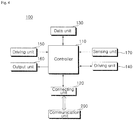
- FIG. 4 is a block diagram schematically illustrating a control configuration of units of the air conditioner according to an embodiment of the present invention.
- a unit of the air conditioner includes a driving unit 140, a sensing unit 170, a communication unit 120, an output unit 160, an input unit 150, a data unit 130, a connecting unit 120, and a controller 110 configured to control an overall operation.
- the unit 100 is connected with the communication unit 200.
- the communication unit 200 may be installed at an inside or outside of the unit 100.
- each unit 100 in common and a separate configuration may be added according to a characteristic of a product.
- the outdoor unit 10 includes a compressor, an outdoor unit fan, and a plurality of valves.
- the driving unit of the outdoor unit may include a compressor driver, an outdoor fan driver, and a valve controller.
- the indoor unit 20 includes a louver or a vane as a wind direction controller.
- the indoor unit 20 may include an indoor unit and a plurality of valves to further include an indoor unit fan driver, a valve controller, and a wind direction controller.
- types, the number, and installation positions of sensor included in the sensing unit 170 may be changed.
- the data unit 130 stores control data for controlling an operation of the unit 100, communication data with respect to an address or group setting for communicating with another unit, data transmitted/received to/from the outside, and operation data generated or sensed during the operation.
- the data unit 130 stores an execution program by function of the unit, data for controlling the operation, and transmitted/received data.
- the data unit 130 may include various storage devices such as ROM, RAM, EPROM, a flash driver, and a hard driver in a hardware scheme.
- the input unit 150 includes at least one such as buttons, switches, and a touch input means.
- buttons, switches, and a touch input means When a user command or predetermined data corresponding to operation of an input means is input to the input unit 150, the input unit 150 provides the input data to the controller 110.
- a power key, a trial run key, and an address setting key may be provided in the outdoor unit.
- a power key, a menu input key, an operation setting key, a temperature control key, a wind direction key, and a lock key may be provided in the indoor unit.
- the output unit 160 includes at least one of a lamp of which lighting or blink is controlled, a speaker, and a display to output an operation state of the unit.
- the lamp outputs whether a unit is operated according to presence of lighting, a lighting color, and presence of blink.
- the speaker outputs a predetermined warning sound and a sound effect to output an operation state.
- the display may output a menu screen for controlling a unit, and may output an operation setting or an operation state of the unit with a guide message or warning configured by at least one combination of characters, numbers, and images.
- the sensing unit 170 includes a plurality of sensors.
- the sensing unit 170 may include a pressure sensor, a temperature sensor, a gas sensor, a humidity sensor, and a flow sensor.
- a plurality of temperature sensors are provided and detect and input an indoor temperature, an outdoor temperature, an indoor heat exchanger temperature, an outdoor heat exchanger, and a pipe temperature to the controller 110.
- the pressure sensors are installed at an input port and an output port of the refrigerant pipe to measure and input pressure of an introduced refrigerant and pressure of a discharged refrigerant to the controller 110.
- the pressure sensor may be installed at a water pipe as well as the refrigerant pipe.
- the driving unit 140 supplies operation power to a control target according to a control command from the controller 110 to control drive of the control target.
- the driving unit 140 may separately include a compressor driver, an outdoor fan driver, and a valve controller configured to control a compressor, an outdoor fan, and a valve, respectively.
- the driving unit 140 provides an operation power to motors included in a compressor, an outdoor unit fan, and a valve which allows the compressor, the outdoor unit fan, and the valve to perform a designated operation according to operation of the motors.
- the communication unit 200 includes at least one wireless communication module to communicate with another unit according to a control command from the controller 110.
- the communication unit 200 transmits/receives data between the controller 110, the outdoor unit, and the indoor unit in a wireless communication scheme and provides received data to the controller 110.
- the communication unit 200 stores information on a upper parent node and a lower child node in an air conditioner network.
- the communication unit 200 confirms and transfers data received from the parent node to the child node, and confirms and transmits data received from the child node to the parent node.
- the communication unit 200 may transmit data except for the data with respect to the parent node and the child node in a broadcast scheme, and may transmit data of the parent node and the childe not in a unicast scheme.
- the controller 110 controls data input and output through the input unit 150 and the output unit 160, manages data stored in the data unit 130, and controls transmission/reception of the data through the communication unit 120.
- the controller 110 detects a connection state and a communication state of the communication unit 200 through the connecting unit 120 to determine failure.
- the controller 110 generates a control command according to a request from another unit or operation setting to provide the control command to the driving unit 140.
- the driving unit 140 allows connected configurations, for example, a compressor, an outdoor fan, valves, an indoor unit fan, and a wind direction controller to be operated.
- controller 110 determines an operation state according to data input from a plurality of sensors of the sensing unit 170 to determine presence of failure and to output an error.
- the communication unit 200 communicates using a frequency of sub-giga (GHz) band having excellent transmission and diffraction characteristics by taking into consideration an attenuation effect of a wireless signal due to a wall in a building and an inter-layer obstacle.
- GHz sub-giga
- the communication unit 200 communicates using one of a 400MHz band and a 900MHz band which are unlicensed bands available for a specific small-power radio station.
- the communication unit 120 may selectively use a 400MHz band frequency and a 900MHz band frequency corresponding to different rules according to a zone or a country.
- the communication unit 200 may further include a short range communication module such as a ZigBee module, a Bluetooth module, and a Near Field Communication (NFC) module.
- a short range communication module such as a ZigBee module, a Bluetooth module, and a Near Field Communication (NFC) module.
- NFC Near Field Communication
- the communication unit 200 is connected with the unit 100 through the connection unit 120.
- the communication unit 200 receives and transmits data of the unit through the connecting unit 120 and provides the received data to the unit.
- the communication unit 200 communicates using a frequency of sub-giga (GHz) band to allow communication in walls, bottoms, and obstacles in the building. Since the sub-giga (GHz) band frequency has excellent transmission and diffraction characteristics, an attenuation effect due to walls or an inter-layer obstacle is low.
- GHz sub-giga
- the communication unit 200 communicates using one of a 400MHz band and a 900MHz band which are unlicensed bands available for a specific small-power radio station among sub-giga bands.
- the communication unit 200 may selectively use a 400MHz band frequency and a 900MHz band frequency corresponding to different rules according to a zone or a country.
- the communication unit 200 may further include a short range communication module such as a ZigBee module, a Bluetooth module, and a Near Field Communication (NFC) module.
- a short range communication module such as a ZigBee module, a Bluetooth module, and a Near Field Communication (NFC) module.
- NFC Near Field Communication
- the communication unit 200 may include a plurality of communication modules to communicate with during between the outdoor unit and another indoor unit, between the outdoor unit and a remote controller, and between the outdoor unit and the controller 110 through the same or different communication modules.
- the communication unit 200 may communicate in different communication schemes according to a target by selectively changing a communication scheme corresponding to a communicating target.
- the communication unit 200 may configure a channel according to the communicating target to transmit/receive data.
- Unlicensed frequency bands by country will be described.
- the unlicensed frequency bands at North America or South America may include 902 MHz to 928MHz (FCC Part 15.247).
- the unlicensed frequency bands at Europe may include 433MHz, 915MHz, and 863MHz to 868MHz (ETSIEN300220).
- the unlicensed frequency bands at Japan may include 920 MHz to 928MHz (ARIB STD-T108).
- the unlicensed frequency bands at China may include 920MHz.
- the unlicensed frequency bands at Korea may include 424MHz to 447MHz, and 917MHz to 923.5MHz (KC).
- the unlicensed frequency bands at India may include 867MHz (G.S.R 564(E)).
- the unlicensed frequency bands at Australia may include 433, 915MHz.
- the unlicensed frequency bands at South Africa may include 433 MHz and 915MHz.
- the unlicensed frequency bands at the world may include 2.4GHz and 5.725GHz in common.
- FIG. 5 is a block diagram schematically illustrating a configuration of a communication unit for wireless communication in an air conditioner according to an embodiment of the present invention.
- the communication unit 200 includes an antenna 290, a signal controller 240, a memory 230, a display 260, a unit connector 220, and a communication controller 210 configured to control an overall operation.
- the communication unit communicates using a 400MHz band frequency or a 900MHz band frequency.
- the antenna 290 selectively uses a 400MHz band or a 900MHz band of the sub-giga bands according to a used frequency band.
- a shape and the size of the antenna 290 may be changed according to the used frequency band.
- the length of the antenna is ⁇ /2 or ⁇ /4 of a transmission frequency. Accordingly, when the transmission frequency is 447MHz, a wavelength of the antenna is 0.67m. If A/2 is applied to the transmission frequency, the length of the antenna is 0.34m. If ⁇ /4 is applied to the transmission frequency, the length of the antenna is 0.17m.
- a case of ISM bands (100MHz, 200MHz, 400MHz, 900MHz) among the sub-giga bands has an excellent transmission characteristic in the building so that an inter-layer communication is possible.
- the communication unit communicates using a 400MHz frequency band or a 900MHz frequency band among the above frequency bands by taking into inter-layer communication and the length of the antenna.
- the antenna 290 transmits a signal output from the signal controller 240 in air and receives and provides a signal of a frequency band designated in air the signal controller 240.
- the antenna 290 is installed at an outside of the unit 100. It is preferred that the unit of the air condition includes an external antenna rather than a built-in antenna in order to transmit/receive a wireless signal because there are a plurality of cases of using a case made by iron. Further, since an installation position of the unit 100 is not fixed but the unit 100 may be installed at various positions, the antenna 290 uses an omnidirectional antenna.
- the signal controller 240 converts transmitted/received data according to a reception target or a used communication scheme.
- the signal controller 240 manages and controls transmission and reception of a signal through the antenna.
- the signal controller 240 controls output of a signal by controlling impedance of the antenna 290 to have a preset value.
- the signal controller 240 controls impedance suited to a frequency band of a signal to be transmitted/received through the antenna 290. Since the communication unit 200 uses a sub-giga band of a 400 band or a 900 MHz band, the signal controller 240 performs impedance matching according to a used frequency band.
- the unit connector 220 is electrically connected to the connecting unit 120 to connect the communication unit 200 with the unit 100.
- the unit connector 220 may include a connection terminal coupled with the connecting unit 120 included in the unit 100.
- Each shape of the unit connector and the connecting unit 120 may be changed when the communication unit 200 is provided at an outside of the unit 100 and is provided at an inside thereof.
- the unit connector 220 provides a signal received from the unit 100 to the communication controller 210, and provides a signal of the communication unit 200 to the connecting unit 120 to be transferred to the controller 110.
- the communication controller 210 controls the signal controller 240 to transmit a signal of a designated frequency band as an output in which data of the unit are set. Moreover, the communication controller 210 processes and provides the received data to the unit. In addition, the communication controller 210 controls data to be converted into a designated form according to a used communication scheme.
- the communication controller 210 confirms a communication state of a connected network and determines whether communication is possible to output a determination result through the display 260. When the communication fails, the communication controller 210 allows the display 260 to output a corresponding warning. Moreover, the communication controller 210 transmits communication failure to the unit through the unit connector 220.
- the communication controller 210 periodically exchanges a signal with the unit 100 to receive and store data from the unit 100. When there is a request from another unit, the communication controller 210 generates and transmits a response based on the stored data. If necessary, the communication controller 210 requests data to the unit 100.
- the communication controller 210 stores information on the upper parent node and the lower child node. In a case of a master unit among a plurality of units, the communication controller 210 stores information on all units in a routing table. In a slave unit except for the master unit, the communication controller 210 stores only information on the parent node and the child node without a routing table.
- the communication unit 200 communicates using a sub-giga band frequency due to interlayer communication so that a network bandwidth is small due to a problem of a frequency band, there is a need to minimize network traffic. Accordingly, since each node does not include a routing table and stores only the parent node and the child node so that each node processes only traffic with respect to the parent node and the child node, the communication controller 210 reduces traffic of the network and calculation load of each node.
- the communication controller 210 confirms whether received data is data of a connected unit, and transmits data in a broadcast scheme or a unicast scheme according to a target unit.
- the communication controller 210 confirms and transmits data received form the parent node to the child nod, and data received from the child node to the parent node.
- the communication controller 210 transmits the data to the parent node or the child node in the unicast scheme. Meanwhile, when the reception target of the data is the parent node and the child node, the communication controller 210 transmits the data in the broadcast scheme. Meanwhile, although a reception target is not the parent node, the communication controller 210 transmits data received from the child node to the parent node in the unicast scheme.
- the communication controller 210 controls the data to be transmitted through a designated channel.
- the communication controller 210 When the communication controller 210 transmits data to a specific target according to a request from a unit 100, the communication controller 210 confirms an address of a corresponding unit to convert data so that the data are transmitted to a designated unit through an antenna.
- the communication controller 210 confirms whether received data are data of the unit to transfer the data to another unit or the unit so that another unit or the unit processes. Before transferring the data to the unit, the communication controller 210 converts the data into a processable form of the unit to transmit the converted data.
- the display 260 outputs an operation state, a network connection state, and a transmission/reception state of the data of the communication unit 200.
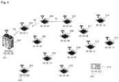
- FIG. 6 is a diagram illustrating a process of transferring data between units of an air conditioner according to an embodiment of the present invention.
- a plurality of units communicates in a wireless scheme using a sub-giga (Sub-GHz) band frequency.
- Sub-GHz sub-giga
- a frequency band is reduced, an available bandwidth is reduced. If the frequency band is increased, an available bandwidth is increased. When the sub-giga band is used, the frequency band is low so that a bandwidth becomes narrower. Accordingly, when a routing scheme such as 2.4G ZigBee(250Kbps) is applied, a signal is delayed due to increase of traffic.
- a routing scheme such as 2.4G ZigBee(250Kbps) is applied, a signal is delayed due to increase of traffic.
- the present invention restrictively uses routing information stored in each node in a specific node in order to reduce traffic of a network.
- Each unit is operated as one node, and one of a plurality of units is configured as a master node.
- a first outdoor unit 201 is a master node and remaining units 202 to 214 are a slave node.
- the indoor units 202 to 214 or the controller 215 may be configured as a master node.
- the indoor unit is connected with the outdoor unit through a refrigerant pipe to be operated in connection with each other, it is preferred that the outdoor unit or the control unit 50 is configured as a master.
- the master node stores a routing table including information on all nodes
- the slave node stores only information on the parent node and the child node in the routing table. Further, when a plurality of nodes replaces the routing table, the nodes replace only information on the parent node. Accordingly, the child node performs only routing with respect to the parent node and the child node to reduce traffic.
- the first outdoor unit 201 is configured as a mater node, and first to thirteenth indoor units 202 to 214 are configured as a slave node being first to thirteenth nodes.
- the controller 215 may be configured as master or slave. The master node always becomes the uppermost node.
- An address is set to each node.
- An address of 00 00 00(251) is set to the first outdoor unit 201 being a master node.
- An address of 00 00 03(252) is set to the fourth indoor unit.
- An address of FF FF FF (253) may be set to the controller 215.
- An address of an indoor unit being a slave node may be set according to an address of a connected outdoor unit. For example, since the address of the first outdoor unit 201 is 00 00 00, an address of 00 00 01 to 00 00 13 is set to the indoor unit. Meanwhile, when the address of the second outdoor unit is 00 01 00, an address of 00 01 01 to 00 01 13 may be set to the indoor unit connected with the second outdoor unit.
- a plurality of indoor units is not installed at one indoor zone but distributed at a plurality of indoor zones, and is not installed at one layer but is installed at a plurality of layers. Accordingly, each indoor unit may transfer a signal of another unit as an intermediate node. A node located beyond a reach distance of a frequency signal at a sub-giga band receives signals from another node.
- the slave node transmits data received from the parent node to the childe node, and transmits all data received from the child node to the parent node. However, when a reception target of the data is the slave node, the slave node generates and transmits a response to the parent node.
- the first indoor unit 201 being the master node communicates with the third indoor unit 207 as follows.
- a parent node of the third indoor unit 207 is the second indoor unit 206, and a parent node of the second indoor unit 206 is the first indoor unit 202.
- the parent node of the first indoor unit 202 is the first outdoor unit 201 being a master node, and a second indoor unit 206 is the child node.
- the childe node of the second indoor unit is the third indoor unit 207.
- the first outdoor unit 201 When the first outdoor unit 201 being the master node transmits data to the third indoor unit 207, the first outdoor unit 201 transmits data to the third outdoor unit 207 based on the stored routing table.
- the first outdoor unit 201 transmits data to the first outdoor unit 201 based on a hierarchy structure of a network table.
- the first outdoor unit 201 receives data from the first indoor unit being a parent node and confirms whether the received data is data of the first outdoor unit 201 to transmit the data to the second indoor unit 206 being a child node.
- the second indoor unit 206 confirms whether the received data is data of the second indoor unit 206 to transmit the data to the third indoor unit 207 being the child node.
- the third indoor unit 207 confirms data of the third indoor unit 207 to change operation setting or operation.
- the third indoor unit 307 generates response data to transmit the response data to the second indoor unit 206 being the parent node.
- the second indoor unit 206 transmits received data to the first indoor unit 202 being a parent node, and the first indoor unit 202 transmits data to the first outdoor unit 201 being a parent node.
- Each node transmits data received from the childe node to the parent node so that data are transferred to the first outdoor unit being a master node.
- the second indoor unit 206 fails to stop or communication is impossible, although the third indoor unit 207 transmits the data, the second indoor unit cannot receive the data.
- the second indoor unit 206 When the second indoor unit 206 is operating, if data is not received for a predetermined time or longer, the second indoor unit 206 automatically turns-off the power to be again driven.
- the second indoor unit 206 After the second indoor unit 206 restarts, if a normal operation is possible, the second indoor unit 206 receives and transmits data of the third indoor unit to the first indoor unit.
- the second indoor unit 206 restarts, if the second indoor unit 206 is not normally operated, the second indoor unit 206 outputs an error. Further, in a case where an operation of the second indoor unit is impossible so that power is turned-off, if the first indoor unit 202 does not receive the data from the second indoor unit for a predetermined time, the first indoor unit 202 outputs a communication error.
- the master node may determine a failure occurring position based on the communication error.
- the master node determines that the second indoor unit fails.
- the mater node or the slave node may retransmit the data after a predetermined time elapses or may transmit data in a normal communication state.
- each node When transmission of the data fails, since each node stores only information on the parent node and the child node in a routing table, it is impossible to search another path. Accordingly, each node processes that transmission of corresponding data fails to output an error. The node with the error restarts. If the node is normally operated after restart, the node again requests or transmits the data.
- the plurality of nodes periodically exchange signals with the parent node or the child node. When the signals are not exchanged for a predetermined time or longer, the plurality of nodes determines that the parent node or the child node fails to output an error.
- FIG. 7 is a diagram illustrating network information stored in a unit for wireless communication of an air conditioner according to an embodiment of the present invention.
- each node includes a routing table.
- a routing table 255 with respect to all nodes is stored in the first outdoor unit 201 being the master node.
- the routing table 255 includes an entire address 263 with respect to the lower slave node.
- the slave node stores a routing table including addresses of the parent node and the child node.
- the first indoor unit 202 stores an address 258 of a first outdoor unit being a parent node and an address 259 of a second indoor unit being a child node.
- the second indoor unit stores an address 261 of a first indoor unit being a parent node, and an address 262 of a third indoor unit being a child node.
- the first indoor unit stores an address 00 00 00 of the first outdoor unit and an address 00 00 04 of the second indoor unit.
- the second indoor unit stores an address 00 00 01 of the first indoor unit and an address 00 00 05 of the third indoor unit.
- the present invention uses a combination of a ZigBee type routing algorithm and Sub-GHz.
- the present invention may use the combination of one of a distance vector algorithm, a link state algorithm, and a complex scheme and the sub-giga band.
- a distance vector algorithm for searching adjacent devices rarely uses a memory, has a high transmission success rate through routing, and easily searches another device upon path loss.
- communication traffic is high, and when a band width is insufficient, there is a limitation in transmitting/receiving data.
- An address system based link state algorithm allows rapid response through an optimal path, may minimize use of a band width, and have a high transmission success rate.
- the address system based link state algorithm frequently uses a memory, and has a difficulty in finding another path upon path loss.
- a complex scheme combining the above algorithms with each other has an average use rate of a memory and easily searches another path upon the path loss but has a low transmission success rate.
- FIG. 8 is a scheme diagram illustrating a data transmission flow of a master node and a slave node in wireless communication of the air conditioner according to an embodiment of the present invention.
- a plurality of nodes receives only information on the parent node when performing network association for exchange of a routing table.
- the master node includes an entire network table with respect to all nodes.
- the master node When the master node transmits data to the slave node, the data are transmitted to a communication target. However, the slave node transmits the data to the master node, the slave node transmits the data in an unicast scheme.
- a master node 231 exchanges data with a plurality of slave nodes 232 to 234.
- the master node is a first outdoor unit and a plurality of indoor units is a slave node.
- the master node is a final parent node
- a first slave node uses a master node as a parent node
- a child node is a second slave node.
- the second slave node uses a first slave node as a parent node
- a third slave node is a child node.
- the first slave node 232 When an event is generated in a first slave node (S11), the first slave node 232 sends an association request to a master node being a parent node (S12).
- a master node 231 updates a network table according to the association request (S13).
- the second slave node 233 When an event is generated in a second slave node 233 (S14), the second slave node 233 sends an association request to a first slave node 232 being a parent node (S15). Accordingly, the first master node updates a network table (S16).
- the third slave node 234 sends an association request to a second slave node 233 being a parent node (S17). Accordingly, the second master node updates a network table (S19).
- FIG. 9 is a scheme diagram illustrating a data transmission flow of a plurality of nodes in wireless communication of the air conditioner according to an embodiment of the present invention.
- a ZigBee routing scheme data are transmitted as follows.
- a used amount of a memory according to routing is small.
- Each node includes only information on peripheral nodes at which a signal reaches. However, upon traffic response in order to search a path, a data size is increased.
- the coordinator node when a coordinator node of a network exchanges data with a third node, the coordinator node confirms association with a third node being a target. When there is no association, the coordinator transmits the data to a first node in a broadcast scheme. The first node determines whether the third node is directly associated with the first node. The first node adds an address of the first node to a routing field to transmit the routing field to the second node in a broadcast scheme. Further, the second node determines whether the third node is directly associated with the second node. The second node adds an address of the second node to the routing field to transmit the routing field to the third node. In this case, since the second node is associated with the third node, the second node transmits data in a unicast scheme.
- the third node confirms a routing field of received data, that is, a routing field with respect to the second node to confirm transmission of the data from the second node.
- the third node transmits response data to the second node in the unicast scheme.
- the second node confirms a routing table to transmit data to the first node, and the first node confirms the routing field to transmit the data to the coordinator node.
- Each node includes only information on peripheral nodes at which a signal reaches. However, upon traffic response in order to search a path, a data size is increased.
- the first node compares RSSI in a table with respect to an entire network to calculate an optional path transmitting data the fourth node.
- the first node transmits the data to the second node in a unicast scheme, and the second node compares an RSSI signal in a stored network table to create an optional path.
- the first node determines an optimal path by comparing RSSI with respect to data received in the same manner as in the third node to transmit data in the unicast scheme.
- the fourth node compares RSSI in the network table and calculates an optimal path to the first node to transmit the data to the third node in a unicast scheme.
- the third node transmits the data to the second node by RSSI comparison and the second node transmits the data to the firth node by the RSSI comparison.
- a case of Z wave routing has no presence of specially managing a network.
- An optimal path is obtained based on RSSI data to minimize network traffic. Since all nodes update and store a routing table of an entire network each time nodes are connected with each other, there is a large used amount of a memory.
- the present invention transmits data by applying a routing scheme being a combination of the ZigBee routing scheme and the Z wave routing scheme using a sub-giga band frequency.
- a master node is operated as a coordinator node 241.
- the following is a case where a master node 241 being a coordinator node transmits data to the third node.
- a coordinator node confirms association of a third node being a target node (S31), and transmits data to the first node 242 in a broadcast scheme (S32).
- a first node confirms association with the target node (S33), and transmits data to the second node 243 in the broadcast scheme (S34). Accordingly, the second node confirms association with the target node (S35), and transmits data to the third node 244 in the unicast scheme because the third node is a child node (S36).
- the third node confirms whether the data received from the second node is data of the third node to generate corresponding response data (S37) and to transmit the generated response data to an upper parent node (S38).
- the second node generates response data to the upper node based on received data (S39) and transmits the generated response data to the first node being a parent node in the unicast scheme (S40).
- the first node generates response data to the upper node based on received data (S41), and transmits the generated response data to the first outdoor unit being a parent node in the unicast scheme (S42).
- each node does not store the entire routing table but stores only information on the parent node and the child node and a master node being a coordinator node stores all data by transmitting data using the above routing algorithm, a small amount of a memory is used. Since a connection form of the network is determined, there is no need to continuously search halfway so that a small amount of a bandwidth of the network is used. However, when a problem occurs at a node, a new path may not be searched. Accordingly, as described above, the present invention abandons corresponding data and restarts a node in which an error occurs to retransmit the data.
- FIG. 10 is a flow chart illustrating a control method for wireless communication in the air conditioner according to an embodiment of the present invention.
- a plurality of units except for the master node stores only information on the parent node and the child node and confirms a reception target of a signal to transfer the signal.
- a plurality of node stores a parent node being an upper node and a child node being a lower node in a routing table (S310).
- the master node stores address of all nodes.
- each node confirms whether the received data is data of each node (S330).
- the node When the received data is data of each node, the node generates response data (S370).
- a communication unit converts the received data to determine whether response is possible. When immediate response is possible, the communication unit generates response data based on stored data. Meanwhile, when the immediate response is impossible, the communication unit provides data to a controller and generates response data corresponding to data received from the controller.
- the communication unit transmits the response data to an upper parent node in a unicast scheme (S380).
- the node confirms a target node, that is, a receiver of data to determine whether the node is connected with the target node (S340).
- the node When the node is not connected with the target node, the node transmits data in the broadcast scheme (S350).
- the node When the node is connected with the target node, that is, when the target node is a parent node or a child node, the node transmits data in a unicast scheme (S360).
- the node when the node receives the data from a child node, the node transmits the data to a parent node in a unicast scheme.
- the node updates information on a parent node at a predetermined time interval. In this case, when data is not received for a predetermined time or longer (S390), the node determines that communication fails (S400).
- the node outputs an error (S410), and turns-off power within a predetermined time and again provides power to restart (S420).
- a peripheral node that is, a parent node or a child node of a node in which communication fails does not receive data from a node in which failure occurs
- the node may determines a communication error to transmit error information to a parent node. Accordingly, a master node of a final stage confirms a node in which failure occurs.
- a plurality of nodes is operated as an intermediate node and transmits data which allows a plurality of units to communicate with each other.
- the plurality of nodes stores only information on the parent node and the child node in a routing table to transmit data so that a transmission structure of a network may be simplified to reduce network traffic and load of the node.
Abstract
Description
- This application claims the priority benefit of Korean Patent Application No.
10-2017-0034841, filed on March 20, 2017 - The present invention relates to an air-conditioner and a control method thereof and, more particularly, to an air-conditioner where a plurality of units included in the air conditioner transmit/receive data in a wireless scheme, and a control method thereof.
- An air conditioner is installed to provide a more pleasant indoor environment to persons by discharging cold air to adjust an indoor temperature and to clean indoor air in order to configure a pleasant indoor environment. In general, the air conditioner includes an indoor unit configured by a heat exchanger to be installed at an inside and an outdoor unit configured by a compressor and a heat exchanger to supply refrigerant to the indoor unit.
- In the air conditioner, the indoor unit configured by a heat exchanger and the outdoor unit configured by a compressor are separately controlled. The outdoor unit is connected with the indoor unit through a refrigerant pipe to supply refrigerant compressed from the compressor of the outdoor unit to the heat exchanger of the indoor unit through the refrigerant pipe. The heat-exchanged refrigerant from the heat exchanger of the indoor unit is again introduced into a compressor of the outdoor unit through the refrigerant pipe. Accordingly, the indoor unit introduces cold air into an inside through heat exchange using the refrigerant.
- The air conditioners are connected with each other in a building unit or a small group unit to transmit/receive data, and monitor and control the state of each unit through the transmitted/received data.
- When a plurality of units is connected with each other by a communication line in the air conditioner, the units transmit data to a designated route through a connected communication line according to a connection state of the communication line.
- For example, a communication line of an indoor unit is connected with an outdoor unit, and data of the indoor unit is transmitted to the outdoor unit. The data are transferred to the indoor unit through the outdoor unit. Accordingly, when the control unit communicates with the indoor unit, the data are transferred through the outdoor unit. In this case, the control unit cannot communicate with the indoor unit in one-to-one correspondence.
- Accordingly, there is growing interest in configuring a wireless communication network of an air conditioner which allows a plurality of units to communicate with in a wireless scheme.
- However, when the plurality of units communicate with in the wireless scheme, the units of the air conditioner are not concentrated in one placed but are distributed at a plurality of layers. In particular, the outdoor unit is installed away to be located on a rooftop so that there is a limitation in a distance. A time is delayed to process a wireless signal.
- In particular, some units fail during transferring a signal, a route should be researched for transferring the signal. In this case, great load is applied to units of the air conditioner.
- As described in Korean patent No.
KR1086266B1 - However, in the wireless network, when a scale of the network is increased, a cost of a wireless communication device is increased. In a case of the parent node, there is a need for large storage capacity for the routing table to increase calculation load. In the tree structure, since the node is divided into a master, a slave, and a repeater, software should be mounted so that each node is differently operated according to a role thereof.
- When the wireless network is simply applied to the air conditioner, since the units of the air conditioner perform functions as each node, but there is a limitation in storage capacity and performs large amount of calculation, it is difficult to apply a complex routing scheme so that it is difficult to easily transfer signals.
- Accordingly, when a signal is blocked midway, the air conditioner cannot rapidly deal with the above. Due to blocking of the signal, the air conditioner cannot normally operate.
- The present invention provides an air conditioner and a control method thereof and, more particularly, to an air-conditioner where a plurality of units included in the air conditioner transmit/receive data in a wireless scheme, and a control method thereof.
- According to an aspect of the present invention, there is provided an air conditioner including: a plurality of units including an outdoor unit and an indoor unit, and distributed at a plurality of layers; and a control unit configured to monitor and control the plurality of units, wherein the control unit and the plurality of units include a communication unit configured to transmit/receive data in a wireless communication scheme, respectively, one of the plurality of units is configured as a master node, and remaining units except for the unit configured as the master node are configured as slave nodes, respectively, so that the slave node stores information on an upper parent node and a lower child node in a routing table to transmit data.
- The master node may store a routing table including address information on the plurality of units. The slave node may transmit the received data to the upper parent node or the lower childe node.
- When the slave node receives data from the child node, the slave node may transmit the data to the parent node in a unicast scheme. The slave node determines whether a target node of received data is a connected node, and the slave node transmits the data to the parent node or the child node in a unicast scheme when the target node of received data is the connected node.
- The slave node may determine whether a target node of received data is a connected node, and the slave node may transmit the data in a broadcast scheme when the target node of received data is the connected node. The master node may confirm an address of a target node being a reception target of data to transmit the data in a broadcast scheme.
- The slave node may communicate with the parent node at a preset time interval to update information on the parent node. When data are not received for a preset time or longer, the slave node may determine communication failure to output an error.
- According to another aspect of the present invention, there is provided a control method of an air conditioner including: configuring one of a plurality of units including an outdoor unit and an indoor unit, and distributed at a plurality of layers as master nodes and configuring mainlining units except for the unit configured as the master node as slave nodes, respectively; storing information on an upper parent node and a lower childe node in a routing table by the slave nodes; transmitting data to a second slave node of the slave nodes by the master node; receiving the data from the master node by a first slave node of the slave nodes; determining whether there is a connection of the second slave node by the first slave node; and transmitting the data to the second slave node by the first slave node.
- The master node may transmit the data to the second salve node with reference to a routing table configured to store address information on all nodes.
- The control method of an air conditioner may further include transmitting the data to the second slave node in a unicast scheme by the first slave node when the second slave node is a connection node.
- The control method of an air conditioner may further include: transmitting the data in a broadcast scheme by the first slave node when the second slave node is a connection node; receiving the data from the first slave node by the third slave node; and transmitting the data to the second slave node in a unicast scheme when the third slave node is a child node.
- The control method of an air conditioner may further include: generating response data with respect to the data by the second slave node; and transmitting the data to a preset parent node by the second slave node.
- In the air conditioner and the control method thereof according to the present invention configured as above, since a plurality of units in the air conditioner transmit/receive data in a wireless communication scheme, direction communication between an indoor unit and an indoor unit and between the indoor unit and an outdoor unit may be performed regardless of an installation environment, and the indoor may directly communicate with the control unit without the outdoor unit.
- In the present invention, in order to transmit data in a wireless scheme, the plurality of units in the air conditioner are operated as one node during transferring the data, respectively, a plurality of nodes do not include a routing table and stores only information on a parent node and a child node which are directly connected so that a routing structure may be simplified.
- Further, although the air conditioner includes a plurality of units, it is easy to install the units and to configure a wireless network in the present invention. When the units perform functions of the node, load of each node is reduced. Network traffic of the air conditioner is reduced by minimizing unnecessary routing table so that the transmission efficiency is improved.
- The above and other objects and features of the present invention will become apparent from the following description of preferred embodiments given in conjunction with the accompanying drawings, in which:
-
FIG. 1 is a view schematically showing a configuration of an air conditioner installed at a building according to an embodiment of the present invention; -
FIG. 2 is a view illustrating a configuration of an air conditioner according to an embodiment of the present invention; -
FIG. 3 is a block diagram illustrating communication between units of the air conditioner according to an embodiment of the present invention; -
FIG. 4 is a block diagram schematically illustrating a control configuration of units of the air conditioner according to an embodiment of the present invention; -
FIG. 5 is a block diagram schematically illustrating a configuration of a communication unit for wireless communication in an air conditioner according to an embodiment of the present invention; -
FIG. 6 is a diagram illustrating a process of transferring data between units of an air conditioner according to an embodiment of the present invention; -
FIG. 7 is a diagram illustrating network information stored in a unit for wireless communication of an air conditioner according to an embodiment of the present invention; -
FIG. 8 is a scheme diagram illustrating a data transmission flow of a master node and a slave node in wireless communication of the air conditioner according to an embodiment of the present invention; -
FIG. 9 is a scheme diagram illustrating a data transmission flow of a plurality of nodes in wireless communication of the air conditioner according to an embodiment of the present invention; and -
FIG. 10 is a flow chart illustrating a control method for wireless communication in the air conditioner according to an embodiment of the present invention. - The advantages, the features, and schemes of achieving the advantages and features of the disclosure will be apparently comprehended by those skilled in the art based on the embodiments, which are described later in detail. However, the present invention is not limited to following disclosed embodiments but may be implemented in various different forms. The present embodiments complete the disclosure of the present invention to be provided to a person having ordinary skill in the art to which the invention pertains in order to inform a spirit and scope of the present invention. The present invention is defined by the scope of claims. Like reference numerals designate like elements throughout the specification. Further, in the present invention, a configuration of a control unit and each unit may be implemented by one or more processor or by a hardware device.
- Embodiments of the present invention will be described in detail with reference to the accompanying drawings.
-
FIG. 1 is a view schematically showing a configuration of an air conditioner installed at a building according to an embodiment of the present invention. - As shown in
FIG. 1 , the air conditioner includes anoutdoor unit 10, anindoor unit 20, and acontrol unit 50. The air conditioner may include a ventilation system, an air cleaner, a humidifier, and a heater as well as the indoor unit and the outdoor unit, and may further include units such as a chiller, an air conditioning unit, and a cooling unit according to the scale. In the air conditioner, respective units may be connected with each other to be operated in connection with operations of the indoor unit and the outdoor unit. Further, the air conditioner may be connected with a moving device, a security device, and an alarm device in the building to be operated. - The
control unit 50 controls operations of theindoor unit 20 and theoutdoor unit 10 corresponding to an input user command, periodically receives and stores corresponding data with respect to operation states of the indoor unit and the outdoor unit, and outputs the operation states through a monitoring screen. The control unit may be connected with theindoor unit 20 to perform operation setting, lock setting, schedule control, group control with respect to the indoor unit, and peak control and demand control with respect to power use. - The
outdoor unit 10 is connected to theindoor unit 20 through a refrigerant pipe to supply a refrigerant to theindoor unit 20. Furthermore, theoutdoor unit 10 periodically communicates with a plurality of indoor units to transmit/receive data from each other, and an operation of theoutdoor unit 10 is changed according to a changed operation setting. - The
indoor unit 20 includes an electronic expansion valve (not shown) configured to expand a refrigerant supplied from theoutdoor unit 10, an indoor heat exchanger (not shown) configured to heat-exchange a refrigerant, an indoor unit fan (not shown) configured to introduce indoor air into the indoor heat exchanger and to expose the heat-exchanged air to an inside, a plurality of sensors (not shown), and a control means (not shown) configured to control an operation of an indoor unit. - Moreover, the
indoor unit 20 includes an outlet (not shown) configured to discharge heat-exchanged air, and a wind direction control unit (not shown) is provided at the outlet to open/close the outlet and to control a direction of the discharged air. The indoor unit controls sucked air, discharged air, a wind direction by controlling a rotation speed of an indoor unit fan. Theindoor unit 20 may further include an input unit configured to an operation state and setting information of an indoor unit and an input unit configured to input setting data. In this case, theindoor unit 20 may transmit setting information on an operation of the air conditioner to a remote control unit (not shown) which allows the remote control unit to output the setting information and to receive data. - The
outdoor unit 10 is operated in a cooling mode and a heating mode according to data received from the connectedindoor unit 20 or a control command from the control unit to supply a refrigerant to a connectedindoor unit 20. - When a plurality of outdoor units is connected, outdoor units may be connected to a plurality of indoor units, and may supply the refrigerant to the plurality of indoor units through a distributor.
- The
outdoor unit 10 includes at least one compressor configured to compress a refrigerant to discharge gaseous refrigerant of high pressure, an accumulator configured to separate gaseous refrigerant and liquid refrigerant from the refrigerant to prevent non-gasified liquid refrigerant from be introduced into the compressor, an oil recovering device configured to recover oil from the refrigerant discharged from the compressor, an outdoor heat exchanger configured to condense or evaporate the refrigerant by heat exchange with an external air, an outdoor fan configured to introduce air into the outdoor heat exchanger and to discharge the heat exchanged air to an outside in order to easily perform heat exchange with the outdoor heat exchanger, a four-way valve configured to change a fluid path of the refrigerant according to an operation mode of the outdoor unit, at least one pressure sensor configured to measure pressure, at least one temperature sensor configured to measure a temperature, and a control configuration configured to control an operation of an outdoor unit and to perform communication with another unit. Although theoutdoor unit 10 further may include a plurality of sensors, valves, and sub-coolers, a detailed description thereof is omitted. - Further, the air conditioner may exchange with other air conditioners through a network such as Internet. The air conditioner may access an external service center, a management server, and a database through a control unit, and may communicate with an external terminal through a network. A terminal may access the air conditioner to monitor and control an operation of the air conditioner by a second control unit.
-
FIG. 2 is a view illustrating a configuration of an air conditioner according to an embodiment of the present invention. - As shown in
FIG. 2 , in an air conditioner, a plurality ofindoor units 20, a plurality ofoutdoor units 10, and acontrol unit 50 transmit/receive data in a wireless communication scheme. - The
outdoor unit 10 is connected to a plurality of indoor units through the refrigerant pipes P1, P2, and P3 to transmits/receive data in a wireless communication scheme. - The
outdoor unit 10 periodically communicates with a plurality ofindoor units 20 to transmit/receive data to and from each other, and an operation is changed according to a changed operation setting from the indoor unit. A plurality of outdoor units and a plurality of indoor units transmit/receive data in a wireless communication scheme. - The
indoor unit 20 communicates with theoutdoor unit 10 and communicates with thecontrol unit 50 in a wireless communication scheme. - The
outdoor unit 10 is connected with the first to thirdindoor units 21 to 23 through a first refrigerant pipe P1. The secondoutdoor unit 12 is connected with the four to sixthindoor units 24 to 26 through a second refrigerant pipe P2. The thirdoutdoor unit 13 is connected with the seventh to ninthindoor units 27 to 29 through a third refrigerant pipe P3. Although the embodiment was described that three indoor units are connected with each outdoor unit for the purpose of convenience or clarity and is illustrative purpose only, the number of indoor units or a shape of the indoor unit is not limited. - When the first
outdoor unit 10 is operated, the refrigerant is supplied to the first to third indoor units. The refrigerant is supplied to the fourth to sixthindoor units 23 to 26 through the second refrigerant pipe P2 by an operation of the secondoutdoor unit 12. The refrigerant is supplied to the seventh to ninthindoor units 27 to 29 from the thirdindoor unit 13 through the third refrigerant unit P3. - In the air conditioner, the group may be configured based on an outdoor unit, and each group communicates with using different channels. Since the indoor unit performs heat exchange based on the refrigerant supplied from the outdoor unit to discharge cold and hot air, it is preferred that the indoor unit and the outdoor unit are configured by one group.
- For example, the first
outdoor unit 11 may form a first group together with the first to thirdindoor units 21 to 23 through the first refrigerant pipe P1. The second outdoor 12 may form a second group together with fourth to sixthindoor units 24 to 26 connected with each other through the second refrigerant pipe P2. The third outdoor 13 may form a third group together with seventh to ninthindoor units 24 to 26 connected with each other through the third refrigerant pipe P3. Further, the outdoor and the control unit may form according to an installation position. A connection state by the refrigerant pipe may be distinguished based on whether a temperature of an indoor unit is changed according to supply of a refrigerant of the outdoor unit by operating the outdoor unit and the indoor unit. - The
control unit 50 communicates with theindoor unit 20 or theoutdoor unit 10 regardless of a group. - The
control unit 50 controls operations of the plurality ofindoor units 20 and outdoorsunits 10 according to an input user command, periodically receives and stores corresponding data with respect to operation states of the plurality of indoor units and outdoor units, and outputs the operation states on a monitor screen. - The
control unit 50 may be connected to the plurality ofindoor unit 20 to perform operating setting, lock setting, schedule control, group control, and group control with respect to the indoor unit, and peak control and demand control with respect to power use. Further, thecontrol unit 50 communicates with the outdoor unit to control an outer unit and to monitor an operation of the outdoor unit. - Further, when a plurality of control unit is provided, the
control units 50 may transmit/receive data through a wireless communication, and may connect with an external control unit through an external network. - When the
control unit 50 and the plurality of units transmit/receive the data in a wireless communication scheme, addresses for communication are stored in the control unit and the plurality of units. Each address may be assigned by the outdoor and the control unit. - As described above, the outdoor unit configures a group with an indoor unit connected by the refrigerant pipe. In this case, an address may be assigned to an indoor unit included in the same group including the outdoor unit. Further, although a group is configured based on the outdoor unit, all outdoor units communicate with all indoor units. Accordingly, the control unit may assign an address for central control as well as address for communication in a group unit to a plurality of units. In some cases, without assigning a separate address, an address assigned to the outdoor and the indoor unit may be used as the address for central control.
-
FIG. 3 is a block diagram illustrating communication between units of the air conditioner according to an embodiment of the present invention.FIG. 3(a) is a block diagram illustrating communication between units using wireless communication.FIG. 3(b) is a block diagram illustrating communication between units using wireless communication according to the present invention. - As shown in
FIG. 3(a) , in the air conditioner, a plurality of units is connected with each other by a communication line. Since there is a limitation in connection of the communication line in the plurality of units, the plurality of units is not connected in one-to-one correspondence but is sequentially connected according to a connection form of the communication line. - The plurality of indoor units is connected with one outdoor unit through the communication line, and the outdoor unit is connected with the
control unit 50. When a plurality of outdoor units is provided, a plurality of indoor units is connected with the outdoor unit based on a connection state of the refrigerant pipe. The plurality of outdoor units is connected with thecontrol unit 50. - The indoor unit transmits data to the outdoor unit, and the outdoor unit transmits outdoor unit data and received indoor unit data to the
control unit 50. Thecontrol unit 50 may confirm an operation state of the indoor unit based on received data. - When the
control unit 50 transfers a control command to the indoor unit, thecontrol unit 50 transmits a control command to an outdoor unit connected with a corresponding indoor unit, and the outdoor unit transmits the received control command to a corresponding indoor unit. - As described above, in a case of communication using wired communication, the plurality of units is not connected with each other in one-to-one correspondence but data are sequentially transmitted according to a connection state of the communication line.
- Accordingly, since data of the indoor unit is not directly transmitted, a time delays to transmit the data. Further, since the outdoor unit should process unit data different from the outdoor unit data, load is increased. Since one outdoor unit should process data of the plurality of indoor units, it takes a long time to transmit data according to the number of connected indoor units.
- As shown in
FIG. 3(b) , theoutdoor unit 10, theindoor unit 20, and thecontrol unit 50 may transmit/receive data in a wireless communication scheme. - The
control unit 50 requests to theoutdoor unit 10 and theindoor unit 20, and determines an operation state of each unit based on the data received from theoutdoor unit 10 and theindoor unit 20 to determine presence of failure. - As described above, the foregoing embodiment has described that a group is configured between the outdoor unit and an indoor unit by taking into consideration a flow of the refrigerant. Not only a communication channel between the outdoor unit and the indoor unit but also a communication channel including the control unit, the outdoor unit, and the indoor unit may be separately configured.
- The
control unit 50 may change operation setting of anindoor unit 20 according to a state (temperature or humidity) of an indoor space in which theindoor unit 20 is installed based on the data received from the indoor unit, and directly transmits data according to operation setting change to the indoor unit. In this case, when operation setting of the indoor unit is changed, thecontrol unit 50 transmits corresponding data to the outdoor unit and accordingly changes an operation of the outdoor unit. - When a schedule is set so that the
indoor unit 20 performs a preset operation at a designated time, thecontrol unit 50 may transmit an operation command to the indoor unit and an outdoor unit connected with the indoor unit. The indoor unit transmits a corresponding response to thecontrol unit 50 and transmits data with respect to an operation state at a predetermined time interval. - The
indoor unit 20 sets an operation to transmit data to the outdoor unit according to data received from the input unit or data received from thecontrol unit 50. - The
outdoor unit 10 calculates the received data of the indoor unit and a load according to an operation state of a plurality of indoor units to control a compressor. - The
outdoor unit 10 or theindoor unit 20 transmits data to thecontrol unit 50 at a predetermined time interval. When breakage or failure occurs, theoutdoor unit 10 or theindoor unit 20 may transmit data with respect to the breakage or the failure. -
FIG. 4 is a block diagram schematically illustrating a control configuration of units of the air conditioner according to an embodiment of the present invention. - As shown in
FIG. 4 , a unit of the air conditioner includes adriving unit 140, asensing unit 170, acommunication unit 120, anoutput unit 160, aninput unit 150, adata unit 130, a connectingunit 120, and acontroller 110 configured to control an overall operation. - Moreover, the
unit 100 is connected with thecommunication unit 200. Thecommunication unit 200 may be installed at an inside or outside of theunit 100. - The above is a configuration included in each
unit 100 in common and a separate configuration may be added according to a characteristic of a product. - For example, the
outdoor unit 10 includes a compressor, an outdoor unit fan, and a plurality of valves. Accordingly, the driving unit of the outdoor unit may include a compressor driver, an outdoor fan driver, and a valve controller. - The
indoor unit 20 includes a louver or a vane as a wind direction controller. Theindoor unit 20 may include an indoor unit and a plurality of valves to further include an indoor unit fan driver, a valve controller, and a wind direction controller. - Further, according to a type of the unit, types, the number, and installation positions of sensor included in the
sensing unit 170 may be changed. - The
data unit 130 stores control data for controlling an operation of theunit 100, communication data with respect to an address or group setting for communicating with another unit, data transmitted/received to/from the outside, and operation data generated or sensed during the operation. Thedata unit 130 stores an execution program by function of the unit, data for controlling the operation, and transmitted/received data. - The
data unit 130 may include various storage devices such as ROM, RAM, EPROM, a flash driver, and a hard driver in a hardware scheme. - The
input unit 150 includes at least one such as buttons, switches, and a touch input means. When a user command or predetermined data corresponding to operation of an input means is input to theinput unit 150, theinput unit 150 provides the input data to thecontroller 110. A power key, a trial run key, and an address setting key may be provided in the outdoor unit. A power key, a menu input key, an operation setting key, a temperature control key, a wind direction key, and a lock key may be provided in the indoor unit. - The
output unit 160 includes at least one of a lamp of which lighting or blink is controlled, a speaker, and a display to output an operation state of the unit. The lamp outputs whether a unit is operated according to presence of lighting, a lighting color, and presence of blink. The speaker outputs a predetermined warning sound and a sound effect to output an operation state. The display may output a menu screen for controlling a unit, and may output an operation setting or an operation state of the unit with a guide message or warning configured by at least one combination of characters, numbers, and images. - The
sensing unit 170 includes a plurality of sensors. Thesensing unit 170 may include a pressure sensor, a temperature sensor, a gas sensor, a humidity sensor, and a flow sensor. - For example, a plurality of temperature sensors are provided and detect and input an indoor temperature, an outdoor temperature, an indoor heat exchanger temperature, an outdoor heat exchanger, and a pipe temperature to the
controller 110. The pressure sensors are installed at an input port and an output port of the refrigerant pipe to measure and input pressure of an introduced refrigerant and pressure of a discharged refrigerant to thecontroller 110. The pressure sensor may be installed at a water pipe as well as the refrigerant pipe. - The driving
unit 140 supplies operation power to a control target according to a control command from thecontroller 110 to control drive of the control target. As described above, in a case of the outdoor unit, the drivingunit 140 may separately include a compressor driver, an outdoor fan driver, and a valve controller configured to control a compressor, an outdoor fan, and a valve, respectively. The drivingunit 140 provides an operation power to motors included in a compressor, an outdoor unit fan, and a valve which allows the compressor, the outdoor unit fan, and the valve to perform a designated operation according to operation of the motors. - The
communication unit 200 includes at least one wireless communication module to communicate with another unit according to a control command from thecontroller 110. Thecommunication unit 200 transmits/receives data between thecontroller 110, the outdoor unit, and the indoor unit in a wireless communication scheme and provides received data to thecontroller 110. - The
communication unit 200 stores information on a upper parent node and a lower child node in an air conditioner network. Thecommunication unit 200 confirms and transfers data received from the parent node to the child node, and confirms and transmits data received from the child node to the parent node. In this case, thecommunication unit 200 may transmit data except for the data with respect to the parent node and the child node in a broadcast scheme, and may transmit data of the parent node and the childe not in a unicast scheme. - The
controller 110 controls data input and output through theinput unit 150 and theoutput unit 160, manages data stored in thedata unit 130, and controls transmission/reception of the data through thecommunication unit 120. Thecontroller 110 detects a connection state and a communication state of thecommunication unit 200 through the connectingunit 120 to determine failure. - The
controller 110 generates a control command according to a request from another unit or operation setting to provide the control command to thedriving unit 140. Accordingly, the drivingunit 140 allows connected configurations, for example, a compressor, an outdoor fan, valves, an indoor unit fan, and a wind direction controller to be operated. - Furthermore, the
controller 110 determines an operation state according to data input from a plurality of sensors of thesensing unit 170 to determine presence of failure and to output an error. - The
communication unit 200 communicates using a frequency of sub-giga (GHz) band having excellent transmission and diffraction characteristics by taking into consideration an attenuation effect of a wireless signal due to a wall in a building and an inter-layer obstacle. - The
communication unit 200 communicates using one of a 400MHz band and a 900MHz band which are unlicensed bands available for a specific small-power radio station. Thecommunication unit 120 may selectively use a 400MHz band frequency and a 900MHz band frequency corresponding to different rules according to a zone or a country. - Further, the
communication unit 200 may further include a short range communication module such as a ZigBee module, a Bluetooth module, and a Near Field Communication (NFC) module. - The
communication unit 200 is connected with theunit 100 through theconnection unit 120. Thecommunication unit 200 receives and transmits data of the unit through the connectingunit 120 and provides the received data to the unit. - The
communication unit 200 communicates using a frequency of sub-giga (GHz) band to allow communication in walls, bottoms, and obstacles in the building. Since the sub-giga (GHz) band frequency has excellent transmission and diffraction characteristics, an attenuation effect due to walls or an inter-layer obstacle is low. - The
communication unit 200 communicates using one of a 400MHz band and a 900MHz band which are unlicensed bands available for a specific small-power radio station among sub-giga bands. Thecommunication unit 200 may selectively use a 400MHz band frequency and a 900MHz band frequency corresponding to different rules according to a zone or a country. - Further, the
communication unit 200 may further include a short range communication module such as a ZigBee module, a Bluetooth module, and a Near Field Communication (NFC) module. - The
communication unit 200 may include a plurality of communication modules to communicate with during between the outdoor unit and another indoor unit, between the outdoor unit and a remote controller, and between the outdoor unit and thecontroller 110 through the same or different communication modules. Thecommunication unit 200 may communicate in different communication schemes according to a target by selectively changing a communication scheme corresponding to a communicating target. - When a different channel is used in communication with the indoor unit and the
control unit 50, thecommunication unit 200 may configure a channel according to the communicating target to transmit/receive data. - According to Korean radio regulations, with respect to the 400MHz frequency band or the 900MHz frequency band, there are 21 channels from 424.7MHz to 424.95MHz and 11 channels from 447.8625MHz to 447.9875MHz for wireless devices for a small output radio station and 32 channels from 917 MHz to 923.5MHz for wireless devices such as RFID/USN, so that the air conditioner may communicate using the above channels.
- Unlicensed frequency bands by country will be described. The unlicensed frequency bands at North America or South America may include 902 MHz to 928MHz (FCC Part 15.247). The unlicensed frequency bands at Europe may include 433MHz, 915MHz, and 863MHz to 868MHz (ETSIEN300220). The unlicensed frequency bands at Japan may include 920 MHz to 928MHz (ARIB STD-T108). The unlicensed frequency bands at China may include 920MHz. The unlicensed frequency bands at Korea may include 424MHz to 447MHz, and 917MHz to 923.5MHz (KC). The unlicensed frequency bands at India may include 867MHz (G.S.R 564(E)). The unlicensed frequency bands at Australia may include 433, 915MHz. The unlicensed frequency bands at South Africa may include 433 MHz and 915MHz. The unlicensed frequency bands at the world may include 2.4GHz and 5.725GHz in common.
- When the North America or the South America uses 902 MHz to 928MHz (FCC Part 15.247), the Europe uses 433MHz, 915MHz, and 863MHz to 868MHz (ETSIEN300220), the Japan uses 920 MHz to 928MHz (ARIB STD-T108), the Korea uses 424MHz to 447MHz, and 917MHz to 923.5MHz (KC), the India uses 867MHz (G.S.R 564(E)), and the world uses 2.4GHz and 5.725GHz in common, communication is possible at transmission speed greater than 50kbps.
-
FIG. 5 is a block diagram schematically illustrating a configuration of a communication unit for wireless communication in an air conditioner according to an embodiment of the present invention. - As shown in
FIG. 5 , thecommunication unit 200 includes anantenna 290, asignal controller 240, amemory 230, adisplay 260, aunit connector 220, and acommunication controller 210 configured to control an overall operation. - Since there are obstacles such as inter-layer wall or furniture, there is a need to use a frequency band which may pass through the obstacles in a building and reach greater than a predetermined distance.
- Accordingly, the communication unit communicates using a 400MHz band frequency or a 900MHz band frequency.
- The
antenna 290 selectively uses a 400MHz band or a 900MHz band of the sub-giga bands according to a used frequency band. - A shape and the size of the
antenna 290 may be changed according to the used frequency band. - For example, the length of the antenna is λ/2 or λ/4 of a transmission frequency. Accordingly, when the transmission frequency is 447MHz, a wavelength of the antenna is 0.67m. If A/2 is applied to the transmission frequency, the length of the antenna is 0.34m. If λ/4 is applied to the transmission frequency, the length of the antenna is 0.17m.
- A case of ISM bands (100MHz, 200MHz, 400MHz, 900MHz) among the sub-giga bands has an excellent transmission characteristic in the building so that an inter-layer communication is possible.
- Since the length of the
antenna 290 is determined according to a band of a transmission frequency, an antenna is long in a case of a 100MHz band or a 200MHz band so that there is a limitation in installation. The communication unit communicates using a 400MHz frequency band or a 900MHz frequency band among the above frequency bands by taking into inter-layer communication and the length of the antenna. - The
antenna 290 transmits a signal output from thesignal controller 240 in air and receives and provides a signal of a frequency band designated in air thesignal controller 240. - Even if the communication unit is mounted inside the
unit 100, theantenna 290 is installed at an outside of theunit 100. It is preferred that the unit of the air condition includes an external antenna rather than a built-in antenna in order to transmit/receive a wireless signal because there are a plurality of cases of using a case made by iron. Further, since an installation position of theunit 100 is not fixed but theunit 100 may be installed at various positions, theantenna 290 uses an omnidirectional antenna. - The
signal controller 240 converts transmitted/received data according to a reception target or a used communication scheme. - Further, the
signal controller 240 manages and controls transmission and reception of a signal through the antenna. Thesignal controller 240 controls output of a signal by controlling impedance of theantenna 290 to have a preset value. Thesignal controller 240 controls impedance suited to a frequency band of a signal to be transmitted/received through theantenna 290. Since thecommunication unit 200 uses a sub-giga band of a 400 band or a 900 MHz band, thesignal controller 240 performs impedance matching according to a used frequency band. - The
unit connector 220 is electrically connected to the connectingunit 120 to connect thecommunication unit 200 with theunit 100. Theunit connector 220 may include a connection terminal coupled with the connectingunit 120 included in theunit 100. Each shape of the unit connector and the connectingunit 120 may be changed when thecommunication unit 200 is provided at an outside of theunit 100 and is provided at an inside thereof. - The
unit connector 220 provides a signal received from theunit 100 to thecommunication controller 210, and provides a signal of thecommunication unit 200 to the connectingunit 120 to be transferred to thecontroller 110. - The
communication controller 210 controls thesignal controller 240 to transmit a signal of a designated frequency band as an output in which data of the unit are set. Moreover, thecommunication controller 210 processes and provides the received data to the unit. In addition, thecommunication controller 210 controls data to be converted into a designated form according to a used communication scheme. - The
communication controller 210 confirms a communication state of a connected network and determines whether communication is possible to output a determination result through thedisplay 260. When the communication fails, thecommunication controller 210 allows thedisplay 260 to output a corresponding warning. Moreover, thecommunication controller 210 transmits communication failure to the unit through theunit connector 220. - The
communication controller 210 periodically exchanges a signal with theunit 100 to receive and store data from theunit 100. When there is a request from another unit, thecommunication controller 210 generates and transmits a response based on the stored data. If necessary, thecommunication controller 210 requests data to theunit 100. - The
communication controller 210 stores information on the upper parent node and the lower child node. In a case of a master unit among a plurality of units, thecommunication controller 210 stores information on all units in a routing table. In a slave unit except for the master unit, thecommunication controller 210 stores only information on the parent node and the child node without a routing table. - Since the
communication unit 200 communicates using a sub-giga band frequency due to interlayer communication so that a network bandwidth is small due to a problem of a frequency band, there is a need to minimize network traffic. Accordingly, since each node does not include a routing table and stores only the parent node and the child node so that each node processes only traffic with respect to the parent node and the child node, thecommunication controller 210 reduces traffic of the network and calculation load of each node. - The
communication controller 210 confirms whether received data is data of a connected unit, and transmits data in a broadcast scheme or a unicast scheme according to a target unit. - The
communication controller 210 confirms and transmits data received form the parent node to the child nod, and data received from the child node to the parent node. - When a reception target of the data is the parent node or the child node, the
communication controller 210 transmits the data to the parent node or the child node in the unicast scheme. Meanwhile, when the reception target of the data is the parent node and the child node, thecommunication controller 210 transmits the data in the broadcast scheme. Meanwhile, although a reception target is not the parent node, thecommunication controller 210 transmits data received from the child node to the parent node in the unicast scheme. - When a communication channel is set in communication between units, the
communication controller 210 controls the data to be transmitted through a designated channel. - When the
communication controller 210 transmits data to a specific target according to a request from aunit 100, thecommunication controller 210 confirms an address of a corresponding unit to convert data so that the data are transmitted to a designated unit through an antenna. - Further, the
communication controller 210 confirms whether received data are data of the unit to transfer the data to another unit or the unit so that another unit or the unit processes. Before transferring the data to the unit, thecommunication controller 210 converts the data into a processable form of the unit to transmit the converted data. - The
display 260 outputs an operation state, a network connection state, and a transmission/reception state of the data of thecommunication unit 200. -
FIG. 6 is a diagram illustrating a process of transferring data between units of an air conditioner according to an embodiment of the present invention. - As shown in
FIG. 6 , a plurality of units communicates in a wireless scheme using a sub-giga (Sub-GHz) band frequency. - If a frequency band is reduced, an available bandwidth is reduced. If the frequency band is increased, an available bandwidth is increased. When the sub-giga band is used, the frequency band is low so that a bandwidth becomes narrower. Accordingly, when a routing scheme such as 2.4G ZigBee(250Kbps) is applied, a signal is delayed due to increase of traffic.
- Since traffic occurs when the routing table is replaced, each node cannot process the signal.
- Accordingly, the present invention restrictively uses routing information stored in each node in a specific node in order to reduce traffic of a network.
- Each unit is operated as one node, and one of a plurality of units is configured as a master node. For example, in the following description, a first
outdoor unit 201 is a master node and remainingunits 202 to 214 are a slave node. Theindoor units 202 to 214 or thecontroller 215 may be configured as a master node. However, since the indoor unit is connected with the outdoor unit through a refrigerant pipe to be operated in connection with each other, it is preferred that the outdoor unit or thecontrol unit 50 is configured as a master. - The master node stores a routing table including information on all nodes, the slave node stores only information on the parent node and the child node in the routing table. Further, when a plurality of nodes replaces the routing table, the nodes replace only information on the parent node. Accordingly, the child node performs only routing with respect to the parent node and the child node to reduce traffic.
- The first
outdoor unit 201 is configured as a mater node, and first to thirteenthindoor units 202 to 214 are configured as a slave node being first to thirteenth nodes. Thecontroller 215 may be configured as master or slave. The master node always becomes the uppermost node. - An address is set to each node.
- An address of 00 00 00(251) is set to the first
outdoor unit 201 being a master node. An address of 00 00 03(252) is set to the fourth indoor unit. An address of FF FF FF (253) may be set to thecontroller 215. - An address of an indoor unit being a slave node may be set according to an address of a connected outdoor unit. For example, since the address of the first
outdoor unit 201 is 00 00 00, an address of 00 00 01 to 00 00 13 is set to the indoor unit. Meanwhile, when the address of the second outdoor unit is 00 01 00, an address of 00 01 01 to 00 01 13 may be set to the indoor unit connected with the second outdoor unit. - A plurality of indoor units is not installed at one indoor zone but distributed at a plurality of indoor zones, and is not installed at one layer but is installed at a plurality of layers. Accordingly, each indoor unit may transfer a signal of another unit as an intermediate node. A node located beyond a reach distance of a frequency signal at a sub-giga band receives signals from another node.
- The slave node transmits data received from the parent node to the childe node, and transmits all data received from the child node to the parent node. However, when a reception target of the data is the slave node, the slave node generates and transmits a response to the parent node.
- The first
indoor unit 201 being the master node communicates with the thirdindoor unit 207 as follows. - A parent node of the third
indoor unit 207 is the secondindoor unit 206, and a parent node of the secondindoor unit 206 is the firstindoor unit 202. The parent node of the firstindoor unit 202 is the firstoutdoor unit 201 being a master node, and a secondindoor unit 206 is the child node. The childe node of the second indoor unit is the thirdindoor unit 207. - When the first
outdoor unit 201 being the master node transmits data to the thirdindoor unit 207, the firstoutdoor unit 201 transmits data to the thirdoutdoor unit 207 based on the stored routing table. - The first
outdoor unit 201 transmits data to the firstoutdoor unit 201 based on a hierarchy structure of a network table. The firstoutdoor unit 201 receives data from the first indoor unit being a parent node and confirms whether the received data is data of the firstoutdoor unit 201 to transmit the data to the secondindoor unit 206 being a child node. The secondindoor unit 206 confirms whether the received data is data of the secondindoor unit 206 to transmit the data to the thirdindoor unit 207 being the child node. - The third
indoor unit 207 confirms data of the thirdindoor unit 207 to change operation setting or operation. The third indoor unit 307 generates response data to transmit the response data to the secondindoor unit 206 being the parent node. - The second
indoor unit 206 transmits received data to the firstindoor unit 202 being a parent node, and the firstindoor unit 202 transmits data to the firstoutdoor unit 201 being a parent node. - Each node transmits data received from the childe node to the parent node so that data are transferred to the first outdoor unit being a master node.
- Meanwhile, when the second
indoor unit 206 fails to stop or communication is impossible, although the thirdindoor unit 207 transmits the data, the second indoor unit cannot receive the data. - When the second
indoor unit 206 is operating, if data is not received for a predetermined time or longer, the secondindoor unit 206 automatically turns-off the power to be again driven. - After the second
indoor unit 206 restarts, if a normal operation is possible, the secondindoor unit 206 receives and transmits data of the third indoor unit to the first indoor unit. - However, after the second
indoor unit 206 restarts, if the secondindoor unit 206 is not normally operated, the secondindoor unit 206 outputs an error. Further, in a case where an operation of the second indoor unit is impossible so that power is turned-off, if the firstindoor unit 202 does not receive the data from the second indoor unit for a predetermined time, the firstindoor unit 202 outputs a communication error. - The master node may determine a failure occurring position based on the communication error. When the first indoor unit does not receive data from the second indoor unit in a normal operation state and the third indoor unit is normally operated, the master node determines that the second indoor unit fails.
- When a communication error occurs, the mater node or the slave node may retransmit the data after a predetermined time elapses or may transmit data in a normal communication state.
- When transmission of the data fails, since each node stores only information on the parent node and the child node in a routing table, it is impossible to search another path. Accordingly, each node processes that transmission of corresponding data fails to output an error. The node with the error restarts. If the node is normally operated after restart, the node again requests or transmits the data.
- The plurality of nodes periodically exchange signals with the parent node or the child node. When the signals are not exchanged for a predetermined time or longer, the plurality of nodes determines that the parent node or the child node fails to output an error.
-
FIG. 7 is a diagram illustrating network information stored in a unit for wireless communication of an air conditioner according to an embodiment of the present invention. - As shown in
FIG. 7 , each node includes a routing table. - As shown in
FIG. 7(a) , a routing table 255 with respect to all nodes is stored in the firstoutdoor unit 201 being the master node. - The routing table 255 includes an
entire address 263 with respect to the lower slave node. - Meanwhile, as shown in
FIG. 7(b) and (c) , the slave node stores a routing table including addresses of the parent node and the child node. - The first
indoor unit 202 stores anaddress 258 of a first outdoor unit being a parent node and anaddress 259 of a second indoor unit being a child node. The second indoor unit stores anaddress 261 of a first indoor unit being a parent node, and anaddress 262 of a third indoor unit being a child node. - The first indoor unit stores an
address 00 00 00 of the first outdoor unit and anaddress 00 00 04 of the second indoor unit. The second indoor unit stores anaddress 00 00 01 of the first indoor unit and anaddress 00 00 05 of the third indoor unit. - In the air conditioner, in order to perform wireless communication in a building, there is a need to use a wireless communication protocol of a Sub-GHz hand and a routing algorithm.
- The present invention uses a combination of a ZigBee type routing algorithm and Sub-GHz.
- The present invention may use the combination of one of a distance vector algorithm, a link state algorithm, and a complex scheme and the sub-giga band.
- The above routing algorithm is as follows.
- A distance vector algorithm for searching adjacent devices rarely uses a memory, has a high transmission success rate through routing, and easily searches another device upon path loss. However, communication traffic is high, and when a band width is insufficient, there is a limitation in transmitting/receiving data.
- An address system based link state algorithm allows rapid response through an optimal path, may minimize use of a band width, and have a high transmission success rate. However, the address system based link state algorithm frequently uses a memory, and has a difficulty in finding another path upon path loss.
- Accordingly, a complex scheme combining the above algorithms with each other has an average use rate of a memory and easily searches another path upon the path loss but has a low transmission success rate.
-
FIG. 8 is a scheme diagram illustrating a data transmission flow of a master node and a slave node in wireless communication of the air conditioner according to an embodiment of the present invention. - Further, a plurality of nodes receives only information on the parent node when performing network association for exchange of a routing table. The master node includes an entire network table with respect to all nodes.
- When the master node transmits data to the slave node, the data are transmitted to a communication target. However, the slave node transmits the data to the master node, the slave node transmits the data in an unicast scheme.
- If each node repeats to transmit the data to the parent node, the data are finally transmitted to the master node.
- As shown in
FIG. 8 , amaster node 231 exchanges data with a plurality ofslave nodes 232 to 234. The master node is a first outdoor unit and a plurality of indoor units is a slave node. - The master node is a final parent node, a first slave node uses a master node as a parent node, and a child node is a second slave node. Further, the second slave node uses a first slave node as a parent node, and a third slave node is a child node.
- When an event is generated in a first slave node (S11), the
first slave node 232 sends an association request to a master node being a parent node (S12). Amaster node 231 updates a network table according to the association request (S13). - When an event is generated in a second slave node 233 (S14), the
second slave node 233 sends an association request to afirst slave node 232 being a parent node (S15). Accordingly, the first master node updates a network table (S16). - Further, when an event is generated in a third slave node 234 (S17), the third slave node 234 sends an association request to a
second slave node 233 being a parent node (S17). Accordingly, the second master node updates a network table (S19). - Accordingly, respective network routing tables are updated.
-
FIG. 9 is a scheme diagram illustrating a data transmission flow of a plurality of nodes in wireless communication of the air conditioner according to an embodiment of the present invention. - Among routing schemes, a ZigBee routing scheme, data are transmitted as follows.
- A used amount of a memory according to routing is small. Each node includes only information on peripheral nodes at which a signal reaches. However, upon traffic response in order to search a path, a data size is increased.
- For example, when a coordinator node of a network exchanges data with a third node, the coordinator node confirms association with a third node being a target. When there is no association, the coordinator transmits the data to a first node in a broadcast scheme. The first node determines whether the third node is directly associated with the first node. The first node adds an address of the first node to a routing field to transmit the routing field to the second node in a broadcast scheme. Further, the second node determines whether the third node is directly associated with the second node. The second node adds an address of the second node to the routing field to transmit the routing field to the third node. In this case, since the second node is associated with the third node, the second node transmits data in a unicast scheme.
- The third node confirms a routing field of received data, that is, a routing field with respect to the second node to confirm transmission of the data from the second node. The third node transmits response data to the second node in the unicast scheme. The second node confirms a routing table to transmit data to the first node, and the first node confirms the routing field to transmit the data to the coordinator node.
- In a ZigBee routing scheme among routing schemes, a used amount of a memory according to routing is small. Each node includes only information on peripheral nodes at which a signal reaches. However, upon traffic response in order to search a path, a data size is increased.
- Meanwhile, in a case of Z wave routing, data are transmitted as follows.
- For example, when the first node transmits data to the fourth node, the first node compares RSSI in a table with respect to an entire network to calculate an optional path transmitting data the fourth node.
- The first node transmits the data to the second node in a unicast scheme, and the second node compares an RSSI signal in a stored network table to create an optional path. The first node determines an optimal path by comparing RSSI with respect to data received in the same manner as in the third node to transmit data in the unicast scheme.
- The fourth node compares RSSI in the network table and calculates an optimal path to the first node to transmit the data to the third node in a unicast scheme.
- The third node transmits the data to the second node by RSSI comparison and the second node transmits the data to the firth node by the RSSI comparison.
- A case of Z wave routing has no presence of specially managing a network. An optimal path is obtained based on RSSI data to minimize network traffic. Since all nodes update and store a routing table of an entire network each time nodes are connected with each other, there is a large used amount of a memory.
- The present invention transmits data by applying a routing scheme being a combination of the ZigBee routing scheme and the Z wave routing scheme using a sub-giga band frequency.
- As shown in
FIG. 9 , a master node is operated as acoordinator node 241. - The following is a case where a
master node 241 being a coordinator node transmits data to the third node. - A coordinator node confirms association of a third node being a target node (S31), and transmits data to the
first node 242 in a broadcast scheme (S32). - A first node confirms association with the target node (S33), and transmits data to the
second node 243 in the broadcast scheme (S34). Accordingly, the second node confirms association with the target node (S35), and transmits data to thethird node 244 in the unicast scheme because the third node is a child node (S36). - The third node confirms whether the data received from the second node is data of the third node to generate corresponding response data (S37) and to transmit the generated response data to an upper parent node (S38).
- The second node generates response data to the upper node based on received data (S39) and transmits the generated response data to the first node being a parent node in the unicast scheme (S40).
- The first node generates response data to the upper node based on received data (S41), and transmits the generated response data to the first outdoor unit being a parent node in the unicast scheme (S42).
- In the present invention, each node does not store the entire routing table but stores only information on the parent node and the child node and a master node being a coordinator node stores all data by transmitting data using the above routing algorithm, a small amount of a memory is used. Since a connection form of the network is determined, there is no need to continuously search halfway so that a small amount of a bandwidth of the network is used. However, when a problem occurs at a node, a new path may not be searched. Accordingly, as described above, the present invention abandons corresponding data and restarts a node in which an error occurs to retransmit the data.
-
FIG. 10 is a flow chart illustrating a control method for wireless communication in the air conditioner according to an embodiment of the present invention. - As described above, a plurality of units except for the master node stores only information on the parent node and the child node and confirms a reception target of a signal to transfer the signal.
- As shown in
FIG. 10 , a plurality of node stores a parent node being an upper node and a child node being a lower node in a routing table (S310). The master node stores address of all nodes. - If data are received (S320), each node confirms whether the received data is data of each node (S330).
- When the received data is data of each node, the node generates response data (S370). A communication unit converts the received data to determine whether response is possible. When immediate response is possible, the communication unit generates response data based on stored data. Meanwhile, when the immediate response is impossible, the communication unit provides data to a controller and generates response data corresponding to data received from the controller.
- The communication unit transmits the response data to an upper parent node in a unicast scheme (S380).
- Meanwhile, when the received data is not the data of each node, the node confirms a target node, that is, a receiver of data to determine whether the node is connected with the target node (S340).
- When the node is not connected with the target node, the node transmits data in the broadcast scheme (S350).
- When the node is connected with the target node, that is, when the target node is a parent node or a child node, the node transmits data in a unicast scheme (S360).
- However, when the node receives the data from a child node, the node transmits the data to a parent node in a unicast scheme.
- Meanwhile, the node updates information on a parent node at a predetermined time interval. In this case, when data is not received for a predetermined time or longer (S390), the node determines that communication fails (S400).
- The node outputs an error (S410), and turns-off power within a predetermined time and again provides power to restart (S420).
- After restart, if the node is normally operated, communication restarts.
- Since a peripheral node, that is, a parent node or a child node of a node in which communication fails does not receive data from a node in which failure occurs, the node may determines a communication error to transmit error information to a parent node. Accordingly, a master node of a final stage confirms a node in which failure occurs.
- In the present invention, a plurality of nodes is operated as an intermediate node and transmits data which allows a plurality of units to communicate with each other. The plurality of nodes stores only information on the parent node and the child node in a routing table to transmit data so that a transmission structure of a network may be simplified to reduce network traffic and load of the node.
- Although the foregoing embodiment has described that all constituent elements configuring the embodiment of the present invention are combined as one to be operated, the present invention is not limited thereto the above embodiments. At least one of all the constituent elements selectively combined with each other to be operated according to the embodiment within the spirit and scope of the principles of the present invention.
- While the present invention has been shown and described in connection with the embodiments, it will be apparent to those skilled in the art that modifications and variations can be made without departing from the spirit and scope of the invention as defined by the appended claims.
Claims (15)
- An air conditioner comprising:a plurality of units including an outdoor unit (10) and an indoor unit (20), and distributed at a plurality of layers; anda control unit (50) configured to monitor and control the plurality of units,wherein the control unit (50) and the plurality of units include a communication unit (200) configured to transmit/receive data in a wireless communication scheme, respectively,one of the plurality of units is configured as a master node, and remaining units except for the unit configured as the master node are configured as slave nodes, respectively, so that the slave node is configured to store information on an upper parent node and a lower child node in a routing table (255) to transmit data.
- The air conditioner of claim 1, wherein the master node is configured to store a routing table (255) including address information on the plurality of units, and
the slave node is configured to transmit the received data to the upper parent node or the lower child node. - The air conditioner of claim 1 or 2, wherein when the slave node is configured to receive data from the child node, the slave node is configured to transmit the data to the parent node in a unicast scheme.
- The air conditioner of any one of claims 1 to 3, wherein the slave node is configured to determine whether a target node of received data is a connected node, and the slave node is configured to transmit the data to the parent node or the child node in a unicast scheme when the target node of received data is the connected node,and
the slave node is configured to transmit the data in a broadcast scheme when the target node of received data is the connected node. - The air conditioner of claim 1, wherein the master node is configured to confirm an address of a target node being a reception target of data to transmit the data in a broadcast scheme.
- The air conditioner of any one of claims 1 to 5, wherein the slave node is configured to communicate with the parent node at a preset time interval to update information on the parent node, and
when data are not received for a preset time or longer, the slave node is configured to determine communication failure to output an error. - The air conditioner of claim 6, wherein when the communication failure occurs, the slave node is configured to wait for a predetermined time to turn-off power and restart.
after the slave node restarts, the slave node is configured to restart to communicate. - A control method of an air conditioner comprising:configuring one of a plurality of units including an outdoor unit (10) and an indoor unit (20), and distributed at a plurality of layers as master nodes and configuring mainlining units except for the unit configured as the master node as slave nodes, respectively;storing information on an upper parent node and a lower childe node in a routing table by the slave nodes;transmitting data to a second slave node of the slave nodes by the master node;receiving the data from the master node by a first slave node of the slave nodes;determining whether there is a connection of the second slave node by the first slave node; andtransmitting the data to the second slave node by the first slave node.
- The control method of an air conditioner of claim 8, wherein the master node transmits the data to the second salve node with reference to a routing table configured to store address information on all nodes.
- The control method of an air conditioner of claim 8 or 9, further comprising transmitting the data to the second slave node in a unicast scheme by the first slave node when the second slave node is a connection node.
- The control method of an air conditioner of claim 8, further comprising:transmitting the data in a broadcast scheme by the first slave nodewhen the second slave node is a connection node;receiving the data from the first slave node by the third slave node; andtransmitting the data to the second slave node in a unicast scheme when the third slave node is a child node.
- The control method of an air conditioner of claim 8, wherein transmitting the response data to the first slave node in a unicast scheme when the parent node of the second slave node is the first slave node; and
transmitting the response data to the master node being a parent node in the unicast scheme by the first slave node. - The control method of an air conditioner of any one of claims 8 to 11, further comprising:generating response data with respect to the data by the second slave node; andtransmitting the data to a preset parent node by the second slave node.
- The control method of an air conditioner of any one of claims 8 to 13, further comprising outputting a communication error to restart by the second slave node when the data is not received in the second slave node for a preset time or longer.
- The control method of an air conditioner of claim 14, further comprising transmitting a communication error of the second slave node to the master node by the second slave node when the data is not received from the second slave node for the preset time or longer.
Applications Claiming Priority (1)
| Application Number | Priority Date | Filing Date | Title |
|---|---|---|---|
| KR1020170034841A KR102300791B1 (en) | 2017-03-20 | 2017-03-20 | Air-conditioner and method for controlling the same |
Publications (2)
| Publication Number | Publication Date |
|---|---|
| EP3379161A1 true EP3379161A1 (en) | 2018-09-26 |
| EP3379161B1 EP3379161B1 (en) | 2023-10-18 |
Family
ID=61691866
Family Applications (1)
| Application Number | Title | Priority Date | Filing Date |
|---|---|---|---|
| EP18162773.8A Active EP3379161B1 (en) | 2017-03-20 | 2018-03-20 | Air-conditioner control method thereof |
Country Status (4)
| Country | Link |
|---|---|
| US (1) | US10989430B2 (en) |
| EP (1) | EP3379161B1 (en) |
| KR (1) | KR102300791B1 (en) |
| WO (1) | WO2018174512A1 (en) |
Cited By (1)
| Publication number | Priority date | Publication date | Assignee | Title |
|---|---|---|---|---|
| CN111023269A (en) * | 2019-12-30 | 2020-04-17 | 宁波奥克斯电气股份有限公司 | Online detection method and device for multi-split air conditioner indoor unit and multi-split air conditioner |
Families Citing this family (9)
| Publication number | Priority date | Publication date | Assignee | Title |
|---|---|---|---|---|
| DE102017117130A1 (en) * | 2017-07-28 | 2019-01-31 | Ebm-Papst Mulfingen Gmbh & Co. Kg | wireless transmission |
| JP7111944B2 (en) * | 2017-12-13 | 2022-08-03 | ダイキン工業株式会社 | Air-conditioning system, remote control device, and method for storing operation data history of air-conditioner |
| KR102401481B1 (en) * | 2017-12-22 | 2022-05-24 | 삼성전자주식회사 | Appliances and control method thereof |
| CN108616966B (en) * | 2018-04-13 | 2020-05-29 | 珠海格力电器股份有限公司 | Wireless networking method and device of air conditioning system |
| CN109802951B (en) * | 2018-12-28 | 2020-12-29 | 东软集团股份有限公司 | Message forwarding method, device and storage device |
| KR20200086889A (en) | 2019-01-10 | 2020-07-20 | 엘지전자 주식회사 | Air conditioner |
| US11300936B2 (en) * | 2019-03-26 | 2022-04-12 | Lenovo (Singapore) Pte. Ltd. | Extracting EtherCAT datagrams from an EtherCAT frame |
| WO2021182065A1 (en) * | 2020-03-12 | 2021-09-16 | 東芝キヤリア株式会社 | Air-conditioning system management device and air-conditioning system management method |
| CN112203261A (en) * | 2020-10-12 | 2021-01-08 | 北京绿星小绿人科技有限公司 | Charging pile management method and device, electronic equipment and readable storage medium |
Citations (6)
| Publication number | Priority date | Publication date | Assignee | Title |
|---|---|---|---|---|
| EP1321722A2 (en) * | 2001-12-21 | 2003-06-25 | SANYO ELECTRIC Co., Ltd. | Communication network system and data communication method therefor |
| EP1868114A1 (en) * | 2006-06-12 | 2007-12-19 | Konrad-Zuse-Zentrum für Informationstechnik Berlin | Device and method for storing and retrieving objects with multi-dimensionally addressed electronic data |
| KR101086266B1 (en) | 2003-03-27 | 2011-11-24 | 주식회사 젤라인 | A hierarchical medium access control method for point-to-multipoint communication |
| US20150078391A1 (en) * | 2012-06-13 | 2015-03-19 | Mitsubishi Electric Corporation | Air-conditioning system and relay device |
| CN104566828A (en) * | 2015-01-16 | 2015-04-29 | 江苏工程职业技术学院 | Zigbee technology based central air-conditioning cold source monitoring system and method |
| EP3285348A1 (en) * | 2015-01-13 | 2018-02-21 | Trane International Inc. | Sleep current failure detection |
Family Cites Families (34)
| Publication number | Priority date | Publication date | Assignee | Title |
|---|---|---|---|---|
| US6424820B1 (en) * | 1999-04-02 | 2002-07-23 | Interval Research Corporation | Inductively coupled wireless system and method |
| US6775258B1 (en) * | 2000-03-17 | 2004-08-10 | Nokia Corporation | Apparatus, and associated method, for routing packet data in an ad hoc, wireless communication system |
| CN1221106C (en) * | 2001-04-27 | 2005-09-28 | 三菱自动车工业株式会社 | Multiplex communication apparatus for vehicle |
| GB0112017D0 (en) * | 2001-05-17 | 2001-07-11 | Koninkl Philips Electronics Nv | Wireless master-slave distributed communications network |
| US7843855B2 (en) * | 2001-09-13 | 2010-11-30 | Network Foundation Technologies, Llc | System and method for broadcasting content to nodes on computer networks |
| WO2003103222A2 (en) * | 2002-05-31 | 2003-12-11 | Koninklijke Philips Electronics N.V. | Message routing in a radio network |
| JP3977157B2 (en) * | 2002-06-17 | 2007-09-19 | Kddi株式会社 | Route control method and apparatus, and computer program |
| US7293024B2 (en) * | 2002-11-14 | 2007-11-06 | Seisint, Inc. | Method for sorting and distributing data among a plurality of nodes |
| US7243004B2 (en) * | 2004-01-07 | 2007-07-10 | Carrier Corporation | Self-configuring controls for heating, ventilating and air conditioning systems |
| DE102004021385A1 (en) * | 2004-04-30 | 2005-11-17 | Daimlerchrysler Ag | Data communication network with decentralized communication management |
| WO2006001241A1 (en) * | 2004-06-23 | 2006-01-05 | Turbo Data Laboratories Inc. | Node inserting method, device, and program |
| KR100700536B1 (en) * | 2004-10-29 | 2007-03-28 | 엘지전자 주식회사 | Communication system for multi type air conditioner |
| KR100672503B1 (en) * | 2004-12-14 | 2007-01-24 | 엘지전자 주식회사 | Control method for multi-airconditioner |
| US9166812B2 (en) * | 2006-01-31 | 2015-10-20 | Sigma Designs, Inc. | Home electrical device control within a wireless mesh network |
| JP2007312043A (en) * | 2006-05-17 | 2007-11-29 | Omron Corp | Remote i/o system |
| US8886809B2 (en) * | 2007-07-18 | 2014-11-11 | Siemens Industry, Inc. | Wireless node auto-reset function |
| US20100187832A1 (en) * | 2007-07-31 | 2010-07-29 | Johnson Controls Technology Company | Devices for receiving and using energy from a building environment |
| US7688802B2 (en) * | 2008-05-23 | 2010-03-30 | Honeywell International Inc. | System and method for time synchronization in a wireless network |
| EP2347339B1 (en) * | 2008-09-12 | 2017-04-05 | Network Foundation Technologies, LLC | System for distributing content data over a computer network and method of arranging nodes for distribution of data over a computer network |
| KR20100032796A (en) * | 2008-09-18 | 2010-03-26 | 삼성전자주식회사 | Method of controlling air conditioner |
| EP2381737B1 (en) * | 2008-12-19 | 2015-01-21 | Shenyang Institute of Automation of the Chinese Academy of Sciences | Communication method for mesh and star topology structure wireless sensor network |
| US20110317692A1 (en) * | 2010-06-03 | 2011-12-29 | Essence Security International Ltd. | Acknowledgement of communications using shared messages |
| JP5510275B2 (en) * | 2010-11-08 | 2014-06-04 | 株式会社デンソー | Communication system, master node, slave node |
| US9494952B2 (en) * | 2011-03-31 | 2016-11-15 | Trane International Inc. | Systems and methods for controlling multiple HVAC systems |
| KR101232928B1 (en) * | 2011-06-10 | 2013-02-13 | 오텍캐리어 주식회사 | Automatic allocation method of communication address for multiairconditioner system |
| KR101964626B1 (en) * | 2012-01-16 | 2019-04-02 | 엘지전자 주식회사 | Air conditioner and method for distributing addresses of the same |
| US9408251B2 (en) * | 2012-07-24 | 2016-08-02 | Mueller International, Llc | Transmitting data within a mesh network |
| US20140059466A1 (en) | 2012-08-21 | 2014-02-27 | Trane International Inc. | Mobile device with graphical user interface for monitoring a building automation system |
| KR101517084B1 (en) * | 2012-11-12 | 2015-05-04 | 엘지전자 주식회사 | Apparatus for controling air conditioner |
| JP6206483B2 (en) * | 2013-03-29 | 2017-10-04 | 富士通株式会社 | COMMUNICATION METHOD, COMMUNICATION PROGRAM, AND NODE DEVICE |
| US20140348181A1 (en) * | 2013-05-22 | 2014-11-27 | Calxeda, Inc. | Time synchronization between nodes of a switched interconnect fabric |
| WO2015104193A1 (en) * | 2014-01-10 | 2015-07-16 | Koninklijke Philips N.V. | Multi-master bus |
| US9732977B2 (en) * | 2014-09-02 | 2017-08-15 | Johnson Controls Technology Company | Systems and methods for configuring and communicating with HVAC devices |
| TWI604744B (en) * | 2016-11-02 | 2017-11-01 | 財團法人工業技術研究院 | Routing method and wireless node for wireless mesh network |
-
2017
- 2017-03-20 KR KR1020170034841A patent/KR102300791B1/en active IP Right Grant
-
2018
- 2018-03-20 EP EP18162773.8A patent/EP3379161B1/en active Active
- 2018-03-20 WO PCT/KR2018/003209 patent/WO2018174512A1/en active Application Filing
- 2018-03-20 US US15/926,072 patent/US10989430B2/en active Active
Patent Citations (6)
| Publication number | Priority date | Publication date | Assignee | Title |
|---|---|---|---|---|
| EP1321722A2 (en) * | 2001-12-21 | 2003-06-25 | SANYO ELECTRIC Co., Ltd. | Communication network system and data communication method therefor |
| KR101086266B1 (en) | 2003-03-27 | 2011-11-24 | 주식회사 젤라인 | A hierarchical medium access control method for point-to-multipoint communication |
| EP1868114A1 (en) * | 2006-06-12 | 2007-12-19 | Konrad-Zuse-Zentrum für Informationstechnik Berlin | Device and method for storing and retrieving objects with multi-dimensionally addressed electronic data |
| US20150078391A1 (en) * | 2012-06-13 | 2015-03-19 | Mitsubishi Electric Corporation | Air-conditioning system and relay device |
| EP3285348A1 (en) * | 2015-01-13 | 2018-02-21 | Trane International Inc. | Sleep current failure detection |
| CN104566828A (en) * | 2015-01-16 | 2015-04-29 | 江苏工程职业技术学院 | Zigbee technology based central air-conditioning cold source monitoring system and method |
Cited By (1)
| Publication number | Priority date | Publication date | Assignee | Title |
|---|---|---|---|---|
| CN111023269A (en) * | 2019-12-30 | 2020-04-17 | 宁波奥克斯电气股份有限公司 | Online detection method and device for multi-split air conditioner indoor unit and multi-split air conditioner |
Also Published As
| Publication number | Publication date |
|---|---|
| EP3379161B1 (en) | 2023-10-18 |
| KR20180106476A (en) | 2018-10-01 |
| WO2018174512A1 (en) | 2018-09-27 |
| KR102300791B1 (en) | 2021-09-09 |
| US10989430B2 (en) | 2021-04-27 |
| US20180266719A1 (en) | 2018-09-20 |
Similar Documents
| Publication | Publication Date | Title |
|---|---|---|
| EP3379161B1 (en) | Air-conditioner control method thereof | |
| US10551084B2 (en) | Air conditioner | |
| KR102058048B1 (en) | Control method of air-conditioner system | |
| US7814756B2 (en) | Air-conditioning system | |
| US7721558B2 (en) | Multi-air conditioner and group-unit control method thereof | |
| US20060090483A1 (en) | Communication system of a multi-type air-conditioner and method thereof | |
| KR101962628B1 (en) | Multi type air conditioner and controlling method for the same | |
| KR102393603B1 (en) | Air-conditioner and method for controlling the same | |
| KR102039489B1 (en) | Air-conditioner and method | |
| KR101275561B1 (en) | Air-conditioner system in the base station and its control method for the same | |
| KR102063634B1 (en) | Control method of air-conditioner system | |
| KR102106910B1 (en) | Air-conditioner and method | |
| KR20130032779A (en) | Air conditioner and controlling method of the same | |
| KR101972042B1 (en) | Air conditioner system and method for controlling the same | |
| US11493223B2 (en) | Air conditioner | |
| KR20200125058A (en) | Air conditioner | |
| KR101155346B1 (en) | Air conditioner and communication method | |
| JPH1144447A (en) | Air conditioning control system | |
| KR20180105519A (en) | Air-conditioner and method for controlling the same | |
| KR102001935B1 (en) | Air conditioning system and Method for controlling it | |
| KR102000071B1 (en) | Air conditioner system and method for controlling the same | |
| KR102169277B1 (en) | Air-conditioner system | |
| KR101949361B1 (en) | Mobile terminal and electronic device | |
| KR20120098196A (en) | Air conditioner and method | |
| KR20180092759A (en) | Facility System and Method thereof |
Legal Events
| Date | Code | Title | Description |
|---|---|---|---|
| PUAI | Public reference made under article 153(3) epc to a published international application that has entered the european phase |
Free format text: ORIGINAL CODE: 0009012 |
|
| STAA | Information on the status of an ep patent application or granted ep patent |
Free format text: STATUS: REQUEST FOR EXAMINATION WAS MADE |
|
| 17P | Request for examination filed |
Effective date: 20180320 |
|
| AK | Designated contracting states |
Kind code of ref document: A1 Designated state(s): AL AT BE BG CH CY CZ DE DK EE ES FI FR GB GR HR HU IE IS IT LI LT LU LV MC MK MT NL NO PL PT RO RS SE SI SK SM TR |
|
| AX | Request for extension of the european patent |
Extension state: BA ME |
|
| RBV | Designated contracting states (corrected) |
Designated state(s): AL AT BE BG CH CY CZ DE DK EE ES FI FR GB GR HR HU IE IS IT LI LT LU LV MC MK MT NL NO PL PT RO RS SE SI SK SM TR |
|
| STAA | Information on the status of an ep patent application or granted ep patent |
Free format text: STATUS: EXAMINATION IS IN PROGRESS |
|
| 17Q | First examination report despatched |
Effective date: 20191028 |
|
| STAA | Information on the status of an ep patent application or granted ep patent |
Free format text: STATUS: EXAMINATION IS IN PROGRESS |
|
| STAA | Information on the status of an ep patent application or granted ep patent |
Free format text: STATUS: EXAMINATION IS IN PROGRESS |
|
| GRAP | Despatch of communication of intention to grant a patent |
Free format text: ORIGINAL CODE: EPIDOSNIGR1 |
|
| STAA | Information on the status of an ep patent application or granted ep patent |
Free format text: STATUS: GRANT OF PATENT IS INTENDED |
|
| INTG | Intention to grant announced |
Effective date: 20230508 |
|
| GRAS | Grant fee paid |
Free format text: ORIGINAL CODE: EPIDOSNIGR3 |
|
| GRAA | (expected) grant |
Free format text: ORIGINAL CODE: 0009210 |
|
| STAA | Information on the status of an ep patent application or granted ep patent |
Free format text: STATUS: THE PATENT HAS BEEN GRANTED |
|
| AK | Designated contracting states |
Kind code of ref document: B1 Designated state(s): AL AT BE BG CH CY CZ DE DK EE ES FI FR GB GR HR HU IE IS IT LI LT LU LV MC MK MT NL NO PL PT RO RS SE SI SK SM TR |
|
| REG | Reference to a national code |
Ref country code: GB Ref legal event code: FG4D |
|
| REG | Reference to a national code |
Ref country code: CH Ref legal event code: EP |
|
| REG | Reference to a national code |
Ref country code: DE Ref legal event code: R096 Ref document number: 602018059465 Country of ref document: DE |
|
| REG | Reference to a national code |
Ref country code: IE Ref legal event code: FG4D |
|
| REG | Reference to a national code |
Ref country code: LT Ref legal event code: MG9D |
|
| REG | Reference to a national code |
Ref country code: NL Ref legal event code: MP Effective date: 20231018 |
|
| REG | Reference to a national code |
Ref country code: AT Ref legal event code: MK05 Ref document number: 1622776 Country of ref document: AT Kind code of ref document: T Effective date: 20231018 |
|
| PG25 | Lapsed in a contracting state [announced via postgrant information from national office to epo] |
Ref country code: NL Free format text: LAPSE BECAUSE OF FAILURE TO SUBMIT A TRANSLATION OF THE DESCRIPTION OR TO PAY THE FEE WITHIN THE PRESCRIBED TIME-LIMIT Effective date: 20231018 |
|
| PG25 | Lapsed in a contracting state [announced via postgrant information from national office to epo] |
Ref country code: GR Free format text: LAPSE BECAUSE OF FAILURE TO SUBMIT A TRANSLATION OF THE DESCRIPTION OR TO PAY THE FEE WITHIN THE PRESCRIBED TIME-LIMIT Effective date: 20240119 |
|
| PG25 | Lapsed in a contracting state [announced via postgrant information from national office to epo] |
Ref country code: IS Free format text: LAPSE BECAUSE OF FAILURE TO SUBMIT A TRANSLATION OF THE DESCRIPTION OR TO PAY THE FEE WITHIN THE PRESCRIBED TIME-LIMIT Effective date: 20240218 |
|
| PG25 | Lapsed in a contracting state [announced via postgrant information from national office to epo] |
Ref country code: LT Free format text: LAPSE BECAUSE OF FAILURE TO SUBMIT A TRANSLATION OF THE DESCRIPTION OR TO PAY THE FEE WITHIN THE PRESCRIBED TIME-LIMIT Effective date: 20231018 |