EP3379104A1 - Belt-type continuously variable transmission - Google Patents
Belt-type continuously variable transmission Download PDFInfo
- Publication number
- EP3379104A1 EP3379104A1 EP16866306.0A EP16866306A EP3379104A1 EP 3379104 A1 EP3379104 A1 EP 3379104A1 EP 16866306 A EP16866306 A EP 16866306A EP 3379104 A1 EP3379104 A1 EP 3379104A1
- Authority
- EP
- European Patent Office
- Prior art keywords
- threaded shaft
- actuator
- belt
- nut member
- continuously variable
- Prior art date
- Legal status (The legal status is an assumption and is not a legal conclusion. Google has not performed a legal analysis and makes no representation as to the accuracy of the status listed.)
- Granted
Links
- 230000005540 biological transmission Effects 0.000 title claims abstract description 25
- 230000033001 locomotion Effects 0.000 claims abstract description 57
- 230000007246 mechanism Effects 0.000 claims abstract description 32
- 230000008859 change Effects 0.000 claims description 5
- 230000009467 reduction Effects 0.000 description 6
- 230000006872 improvement Effects 0.000 description 3
- 238000003780 insertion Methods 0.000 description 2
- 230000037431 insertion Effects 0.000 description 2
- 238000012423 maintenance Methods 0.000 description 2
- 238000000034 method Methods 0.000 description 2
- 230000008569 process Effects 0.000 description 2
- 230000008901 benefit Effects 0.000 description 1
- 230000000694 effects Effects 0.000 description 1
- 230000013011 mating Effects 0.000 description 1
- 238000012986 modification Methods 0.000 description 1
- 230000004048 modification Effects 0.000 description 1
- 230000004044 response Effects 0.000 description 1
- 230000000717 retained effect Effects 0.000 description 1
- 238000004804 winding Methods 0.000 description 1
Images


Classifications
-
- F—MECHANICAL ENGINEERING; LIGHTING; HEATING; WEAPONS; BLASTING
- F16—ENGINEERING ELEMENTS AND UNITS; GENERAL MEASURES FOR PRODUCING AND MAINTAINING EFFECTIVE FUNCTIONING OF MACHINES OR INSTALLATIONS; THERMAL INSULATION IN GENERAL
- F16H—GEARING
- F16H25/00—Gearings comprising primarily only cams, cam-followers and screw-and-nut mechanisms
- F16H25/18—Gearings comprising primarily only cams, cam-followers and screw-and-nut mechanisms for conveying or interconverting oscillating or reciprocating motions
- F16H25/20—Screw mechanisms
- F16H25/24—Elements essential to such mechanisms, e.g. screws, nuts
-
- F—MECHANICAL ENGINEERING; LIGHTING; HEATING; WEAPONS; BLASTING
- F16—ENGINEERING ELEMENTS AND UNITS; GENERAL MEASURES FOR PRODUCING AND MAINTAINING EFFECTIVE FUNCTIONING OF MACHINES OR INSTALLATIONS; THERMAL INSULATION IN GENERAL
- F16H—GEARING
- F16H25/00—Gearings comprising primarily only cams, cam-followers and screw-and-nut mechanisms
- F16H25/18—Gearings comprising primarily only cams, cam-followers and screw-and-nut mechanisms for conveying or interconverting oscillating or reciprocating motions
- F16H25/20—Screw mechanisms
-
- F—MECHANICAL ENGINEERING; LIGHTING; HEATING; WEAPONS; BLASTING
- F16—ENGINEERING ELEMENTS AND UNITS; GENERAL MEASURES FOR PRODUCING AND MAINTAINING EFFECTIVE FUNCTIONING OF MACHINES OR INSTALLATIONS; THERMAL INSULATION IN GENERAL
- F16H—GEARING
- F16H63/00—Control outputs from the control unit to change-speed- or reversing-gearings for conveying rotary motion or to other devices than the final output mechanism
- F16H63/02—Final output mechanisms therefor; Actuating means for the final output mechanisms
- F16H63/04—Final output mechanisms therefor; Actuating means for the final output mechanisms a single final output mechanism being moved by a single final actuating mechanism
- F16H63/06—Final output mechanisms therefor; Actuating means for the final output mechanisms a single final output mechanism being moved by a single final actuating mechanism the final output mechanism having an indefinite number of positions
- F16H63/062—Final output mechanisms therefor; Actuating means for the final output mechanisms a single final output mechanism being moved by a single final actuating mechanism the final output mechanism having an indefinite number of positions electric or electro-mechanical actuating means
-
- F—MECHANICAL ENGINEERING; LIGHTING; HEATING; WEAPONS; BLASTING
- F16—ENGINEERING ELEMENTS AND UNITS; GENERAL MEASURES FOR PRODUCING AND MAINTAINING EFFECTIVE FUNCTIONING OF MACHINES OR INSTALLATIONS; THERMAL INSULATION IN GENERAL
- F16H—GEARING
- F16H9/00—Gearings for conveying rotary motion with variable gear ratio, or for reversing rotary motion, by endless flexible members
- F16H9/02—Gearings for conveying rotary motion with variable gear ratio, or for reversing rotary motion, by endless flexible members without members having orbital motion
- F16H9/04—Gearings for conveying rotary motion with variable gear ratio, or for reversing rotary motion, by endless flexible members without members having orbital motion using belts, V-belts, or ropes
- F16H9/12—Gearings for conveying rotary motion with variable gear ratio, or for reversing rotary motion, by endless flexible members without members having orbital motion using belts, V-belts, or ropes engaging a pulley built-up out of relatively axially-adjustable parts in which the belt engages the opposite flanges of the pulley directly without interposed belt-supporting members
- F16H9/16—Gearings for conveying rotary motion with variable gear ratio, or for reversing rotary motion, by endless flexible members without members having orbital motion using belts, V-belts, or ropes engaging a pulley built-up out of relatively axially-adjustable parts in which the belt engages the opposite flanges of the pulley directly without interposed belt-supporting members using two pulleys, both built-up out of adjustable conical parts
- F16H9/18—Gearings for conveying rotary motion with variable gear ratio, or for reversing rotary motion, by endless flexible members without members having orbital motion using belts, V-belts, or ropes engaging a pulley built-up out of relatively axially-adjustable parts in which the belt engages the opposite flanges of the pulley directly without interposed belt-supporting members using two pulleys, both built-up out of adjustable conical parts only one flange of each pulley being adjustable
Definitions
- the present invention relates to an improvement of a belt-type continuously variable transmission that includes a drive pulley that is supported on an input shaft, a driven pulley that is supported on an output shaft, a belt that is wound around the two pulleys, and an actuator that can change a groove width of either one of the two pulleys.
- an actuator of such a belt-type continuously variable transmission as disclosed in Patent Document 1 below, an actuator having a motor and a screw feed mechanism that includes a nut member that is rotated by receiving rotational power of the motor and a threaded shaft that converts rotation of the nut member into linear motion and drives a pulley is already known.
- Patent Document 1 Japanese Patent Application Laid-open No. 2012-21609
- the present invention has been accomplished in light of such circumstances, and it is an object thereof to obtain a belt-type continuously variable transmission that enables the stroke position of a threaded shaft to be easily adjusted even when a screw feed mechanism in which the efficiency of converting linear motion of the threaded shaft into rotary motion is lower than the efficiency of converting rotary motion into linear motion is used.
- a belt-type continuously variable transmission comprising a drive pulley that is supported on an input shaft, a driven pulley that is supported on an output shaft, a belt that is wound around the two pulleys, and an actuator that can change a groove width of either one of the two pulleys, the actuator having a motor and a screw feed mechanism that includes a nut member and a threaded shaft, the nut member being rotated by receiving rotational power of the motor, the threaded shaft converting rotation of the nut member into linear motion and changing a groove width of the either one of the pulley, and the actuator being provided with an operation part that can make the nut member rotate without depending on the rotational power of the motor.
- the efficiency when linear motion of the threaded shaft is converted into rotary motion is lower than the efficiency when rotary motion is converted into linear motion.
- one end of the threaded shaft extends through a housing forming an outer shell of the actuator and is exposed outside, and the actuator is provided with restriction means that restricts the maximum amount of stroke in a linear motion direction toward the one end side of the threaded shaft.
- the transmission comprises an arm that is linked to the either one of the pulleys via a bearing and a case that houses the two pulleys, the belt, and the arm, the actuator being mounted on the case with the threaded shaft inserted into the case in order to connect the threaded shaft and the arm, and the maximum amount of stroke in the linear motion direction toward the one end side of the threaded shaft, which is restricted by the restriction means, being set to be longer than a maximum distance from a mounting face of the actuator via which the actuator is mounted on the case up to the arm.
- the actuator comprises a power transmitting gear that transmits rotational power of the motor, the operation part being provided on a rotating shaft of the power transmitting gear, and the nut member of the screw feed mechanism being made rotatable by operating the operation part so as to rotate the power transmitting gear.
- a housing forming an outer shell of the actuator is provided with an opening enabling operation of the operation part and a lid member for covering the opening.
- the actuator is provided with a rotation-preventing part that prevents the threaded shaft from rotating accompanying rotation of the nut member by contacting the threaded shaft of the screw feed mechanism.
- An outer wall face 14a of an embodiment corresponds to the mounting face of the present invention
- a stepped gear 23 of the embodiment corresponds to the power transmitting gear of the present invention
- a C ring 30 of the embodiment corresponds to the restriction means of the present invention.
- the operation part which can rotate the nut member of the screw feed mechanism without depending on the rotational power of the motor, is provided on the actuator, it is possible to make the threaded shaft stroke by operating the operation part and rotating the nut member. Therefore, even when a screw feed mechanism in which the reverse efficiency of a screw is lower than the forward efficiency is used, it is possible to easily adjust the stroke position of the threaded shaft. Because of this, when the actuator is mounted on the transmission case, even if the stroke position of the threaded shaft is not precisely adjusted in advance, it becomes possible to adjust it to a prescribed position by gauging when mounting on the case, thus improving the ease of assembly. Particularly when the stroke position must be adjusted by inserting the threaded shaft into a case that is already mounted on a vehicle body, etc., the ease of assembly can be improved to a great extent.
- the first aspect of the present invention can be exhibited effectively.
- FIG. 1 is a plan sectional view of a belt-type continuously variable transmission related to the present invention
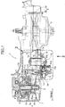
- FIG. 2 is a view in the direction of arrow 2 in Fig. 1 .
- the belt-type continuously variable transmission 1 includes an input shaft 2 to which power is transmitted from a drive source such as an engine or a motor, which is not illustrated, an output shaft 3 that is parallel to the input shaft 2 and transmits power to a wheel, which is not illustrated, a drive pulley 4 that is supported on the input shaft 2, a driven pulley 5 that is supported on the output shaft 3, a belt 6 that is wound around the two pulleys 4 and 5, a case 7 that houses the two pulleys 4 and 5 and the belt 6, and an actuator 12 that is mounted on the case 7 and can change the groove width of either one of the drive pulley 4 and the driven pulley 5, the belt-type continuously variable transmission 1 being installed in a vehicle such as a two-wheeled motor vehicle.
- a drive source such as an engine or a motor
- an output shaft 3 that is parallel to the input shaft 2 and transmits power to a wheel
- a drive pulley 4 that is supported on the input shaft 2
- a driven pulley 5 that is supported
- the drive pulley 4 is formed from a drive-side fixed sheave 4a that is fixed to the input shaft 2 and a drive-side movable sheave 4b that is supported on the input shaft 2 and is movable in the axial direction of the input shaft 2, and the driven pulley 5 is formed from a driven-side fixed sheave 5a that is fixed to the output shaft 3 and a driven-side movable sheave 5b that is supported on the output shaft 3 and is movable in the axial direction of the output shaft 3.
- a ramp plate 8 is fixed to the input shaft 2 behind the drive-side movable sheave 4b, and a plurality of centrifugal weights 9 are retained between the drive-side movable sheave 4b and the ramp plate 8.
- the centrifugal weight 9 moves radially outward along a cam face of the drive-side movable sheave 4b, the drive-side movable sheave 4b is moved toward the drive-side fixed sheave 4a side, and the winding radius of the belt 6 increases.
- an arm 11 is relatively rotatably linked to one of the movable sheaves 4b and 5b of the two pulleys 4 and 5, the drive-side movable sheave 4b in this embodiment, via a bearing 10, and the actuator 12 is connected to the arm 11 so that a hook portion 13a formed on a threaded shaft 13 engages with a pin 11a formed on the arm 11, the actuator 12 moving the drive-side movable sheave 4b in the axial direction of the input shaft 2 via the arm 11 and changing the groove width of the drive pulley 4 in cooperation with centrifugal weight 9.
- the female thread 21a and the male thread 13b are formed as trapezoidal screws, and the efficiency (reverse efficiency) when linear motion of the threaded shaft 13 is converted into rotary motion is lower than the efficiency (forward efficiency) when rotary motion is converted into linear motion. Because of this, the threaded shaft 13 cannot easily be made to stroke (undergo linear motion) as for a ball screw, but since the operation part 25 that enables the stepped gear 23 to be rotated from the outside of the second housing half body 15 is formed on the end part, on the second housing half body 15 side, of the stepped gear 23, it is possible to rotate the nut member 21 by inserting a tool, which is not illustrated, into the operation part 25 via the opening 15a of the second housing half body 15 and rotating the stepped gear 23, and this enables the threaded shaft 13 to be made to stroke. Therefore, even when a trapezoidal screw for which the reverse efficiency of the screw is lower than the forward efficiency is used, the stroke position (position in the linear motion direction) of the threaded shaft 13 can easily be adjusted.
- a plate-shaped portion 14e that contacts a back face of the hook portion 13a and prevents rotation of the threaded shaft 13 is projectingly provided as a rotation-preventing part on the extremity of the second bulge portion 14d, and prevents rotation of the threaded shaft 13 accompanying rotation of the nut member 21, but the arrangement of the rotation-preventing part is not limited thereto. Furthermore, an opening 14f at the extremity of the second bulge portion 14d through which one end of the threaded shaft 13 extends and is exposed to the outside is sealed with a seal member 32, thus preventing dirt, etc. from entering the housing 16.
- the threaded shaft 13 since one end of the threaded shaft 13 extends through the housing 16 forming an outer shell of the actuator 12 and is exposed to the outside, and the C ring 30 as restriction means that restricts the maximum amount of stroke in the linear motion direction toward the one end side of the threaded shaft 13 is provided on the actuator 12, in the actuator 12 having a structure in which one end of the threaded shaft 13 extends through the housing 16 and is exposed to the outside, it is possible to prevent the threaded shaft 13 from accidentally coming off from the housing 16 due to excessive adjustment when adjusting the stroke position of the threaded shaft 13.
- the actuator 12 is mounted on the case 7 by inserting the threaded shaft 13 into the case 7 in order to connect the threaded shaft 13 and the arm 11, and the maximum amount of stroke of the threaded shaft 13, which is restricted by the C ring 30, is set so as to be longer than the maximum distance 1 from the mounting face 14a of the actuator 12, via which it is mounted on the case 7, up to the arm 11, if the threaded shaft 13 is adjusted in advance to the maximum amount of stroke, when the actuator 12 is mounted on the case 7, even in a state in which the arm 11 is hidden within the case 7 and cannot be seen, a situation in which the threaded shaft 13 cannot reach the arm 11 can be avoided, thus enabling the threaded shaft 13 and the arm 11 to be reliably connected.
- the actuator 12 includes the stepped gear 23, which transmits rotational power of the motor 19, the operation part 25 is provided on the rotating shaft 23c of the stepped gear 23, and the nut member 21 of the screw feed mechanism 31 can be rotated by operating the operation part 25 to rotate the stepped gear 23, compared with a case in which the operation part 25 for rotating the nut member 21 is provided on the nut member 21 itself, the structure of the operation part 25 and the degree of freedom of placement become simple and, moreover, since the rotational torque can be reduced compared with a case in which the nut member 21 is rotated directly, it becomes easy to adjust the stroke position of the threaded shaft 13, and it is possible to prevent the operation part 25 from being broken by a tool, etc.
- the housing 16 forming an outer shell of the actuator 12 is provided with the opening 15a enabling operation of the operation part 25 and the lid member 15b covering the opening 15a, it is possible to improve the ease of maintenance and to prevent foreign matter from entering the housing 16.
- the actuator 12 is provided with the rotation-preventing part 14e, which prevents rotation of the threaded shaft 13 accompanying rotation of the nut member 21 by contacting the threaded shaft 13 of the screw feed mechanism 31, when adjusting the stroke position of the threaded shaft 13, the threaded shaft 13 does not rotate accompanying rotation of the nut member 21. Because of this, it is unnecessary to restrain the threaded shaft 13 so that it does not rotate accompanying rotation of the nut member 21 with one hand while operating the operation part 25 with the other hand, thus achieving an improvement in the ease of assembly.
- the belt-type continuously variable transmission of the present invention is not limited to one that is mounted on a two-wheeled motor vehicle, and may be used in a vehicle of any mode.
- the screw feed mechanism of the actuator of the present invention is not limited to an arrangement in which the efficiency when linear motion of the threaded shaft is converted into rotary motion is lower than the efficiency when rotary motion is converted into linear motion, and a screw feed mechanism of any mode may be employed.
- the connecting mechanism for the threaded shaft and the arm is not limited to connection by a squared U-shaped part and a pin, and various connecting mechanisms such as for example insertion of a pin into a center hole of a donut-shaped portion may be employed.
Landscapes
- Engineering & Computer Science (AREA)
- General Engineering & Computer Science (AREA)
- Mechanical Engineering (AREA)
- Transmission Devices (AREA)
- Transmissions By Endless Flexible Members (AREA)
Abstract
Description
- The present invention relates to an improvement of a belt-type continuously variable transmission that includes a drive pulley that is supported on an input shaft, a driven pulley that is supported on an output shaft, a belt that is wound around the two pulleys, and an actuator that can change a groove width of either one of the two pulleys.
- As an actuator of such a belt-type continuously variable transmission, as disclosed in
Patent Document 1 below, an actuator having a motor and a screw feed mechanism that includes a nut member that is rotated by receiving rotational power of the motor and a threaded shaft that converts rotation of the nut member into linear motion and drives a pulley is already known. - Patent Document 1: Japanese Patent Application Laid-open No.
2012-21609 - In the actuator disclosed in
Patent Document 1 above, since a ball screw is used as the screw feed mechanism, the reverse efficiency (the efficiency with which linear motion of the threaded shaft is converted into rotary motion) of the screw is as high as the forward efficiency (the efficiency with which rotary motion of the threaded shaft is converted into linear motion), and the threaded shaft can easily carry out a stroke (linear motion). Because of this, when mounting the actuator on a transmission case, it is possible to adjust the stroke position (position in the linear motion direction) of the threaded shaft to a prescribed position by gauging when mounting it on the case without precisely adjusting the position in advance. However, although there is such an advantage, since the ball screw is expensive, it is the main cause of increased cost of the actuator. - On the other hand, when a screw feed mechanism not employing a ball is used as an inexpensive substitute for the ball screw, since the reverse efficiency of the screw is lower than the forward efficiency, the threaded shaft cannot simply carry out a stroke as for the ball screw. Because of this, it is difficult to adjust the stroke position of the threaded shaft after the actuator is mounted on the transmission case, and the actuator cannot be mounted on the case unless the stroke position of the threaded shaft is adjusted to a prescribed position in advance before mounting it on the case, which is a problem.
- The present invention has been accomplished in light of such circumstances, and it is an object thereof to obtain a belt-type continuously variable transmission that enables the stroke position of a threaded shaft to be easily adjusted even when a screw feed mechanism in which the efficiency of converting linear motion of the threaded shaft into rotary motion is lower than the efficiency of converting rotary motion into linear motion is used.
- In order to attain the above object, according to a first aspect of the present invention, there is provided a belt-type continuously variable transmission comprising a drive pulley that is supported on an input shaft, a driven pulley that is supported on an output shaft, a belt that is wound around the two pulleys, and an actuator that can change a groove width of either one of the two pulleys, the actuator having a motor and a screw feed mechanism that includes a nut member and a threaded shaft, the nut member being rotated by receiving rotational power of the motor, the threaded shaft converting rotation of the nut member into linear motion and changing a groove width of the either one of the pulley, and the actuator being provided with an operation part that can make the nut member rotate without depending on the rotational power of the motor.
- Further, according to a second aspect of the present invention, in addition to the first aspect, with regard to the screw feed mechanism the efficiency when linear motion of the threaded shaft is converted into rotary motion is lower than the efficiency when rotary motion is converted into linear motion.
- Furthermore, according to a third aspect of the present invention, in addition to the first or second aspect, one end of the threaded shaft extends through a housing forming an outer shell of the actuator and is exposed outside, and the actuator is provided with restriction means that restricts the maximum amount of stroke in a linear motion direction toward the one end side of the threaded shaft.
- Moreover, according to a fourth aspect of the present invention, in addition to the third aspect, the transmission comprises an arm that is linked to the either one of the pulleys via a bearing and a case that houses the two pulleys, the belt, and the arm, the actuator being mounted on the case with the threaded shaft inserted into the case in order to connect the threaded shaft and the arm, and the maximum amount of stroke in the linear motion direction toward the one end side of the threaded shaft, which is restricted by the restriction means, being set to be longer than a maximum distance from a mounting face of the actuator via which the actuator is mounted on the case up to the arm.
- Further, according to a fifth aspect of the present invention, in addition to any one of the first to fourth aspects, the actuator comprises a power transmitting gear that transmits rotational power of the motor, the operation part being provided on a rotating shaft of the power transmitting gear, and the nut member of the screw feed mechanism being made rotatable by operating the operation part so as to rotate the power transmitting gear.
- Furthermore, according to a sixth aspect of the present invention, in addition to any one of the first to fifth aspects, a housing forming an outer shell of the actuator is provided with an opening enabling operation of the operation part and a lid member for covering the opening.
- Moreover, according to a seventh aspect of the present invention, in addition to any one of the first to sixth aspects, the actuator is provided with a rotation-preventing part that prevents the threaded shaft from rotating accompanying rotation of the nut member by contacting the threaded shaft of the screw feed mechanism.
- An
outer wall face 14a of an embodiment corresponds to the mounting face of the present invention, astepped gear 23 of the embodiment corresponds to the power transmitting gear of the present invention, and aC ring 30 of the embodiment corresponds to the restriction means of the present invention. - In accordance with the first aspect of the present invention, since the operation part, which can rotate the nut member of the screw feed mechanism without depending on the rotational power of the motor, is provided on the actuator, it is possible to make the threaded shaft stroke by operating the operation part and rotating the nut member. Therefore, even when a screw feed mechanism in which the reverse efficiency of a screw is lower than the forward efficiency is used, it is possible to easily adjust the stroke position of the threaded shaft. Because of this, when the actuator is mounted on the transmission case, even if the stroke position of the threaded shaft is not precisely adjusted in advance, it becomes possible to adjust it to a prescribed position by gauging when mounting on the case, thus improving the ease of assembly. Particularly when the stroke position must be adjusted by inserting the threaded shaft into a case that is already mounted on a vehicle body, etc., the ease of assembly can be improved to a great extent.
- Furthermore, in accordance with the second aspect of the present invention, since a screw feed mechanism is used in which the efficiency when linear motion of the threaded shaft is converted into rotary motion is lower than the efficiency when rotary motion is converted into linear motion, the first aspect of the present invention can be exhibited effectively.
- Moreover, in accordance with the third aspect of the present invention, since restriction means that restricts the maximum amount of stroke in the linear motion direction toward the one end side of the threaded shaft is provided on the actuator, in the actuator having a structure in which one end of the threaded shaft extends through the housing and is exposed to the outside, it is possible to prevent the threaded shaft from accidentally coming off from the housing due to excessive adjustment when adjusting the stroke position of the threaded shaft.
- Furthermore, in accordance with the fourth aspect of the present invention, since the maximum amount of stroke in the linear motion direction toward the one end side of the threaded shaft, which is restricted by the restriction means, is set so as to be longer than the maximum distance from the mounting face of the actuator, via which it is mounted on the case, up to the arm, if the threaded shaft is adjusted in advance to the maximum amount of stroke, when the actuator is mounted on the case, even in a state in which the arm is hidden within the case and cannot be seen, a situation in which the threaded shaft cannot reach the arm can be avoided, thus enabling the threaded shaft and the arm to be reliably connected.
- Moreover, in accordance with the fifth aspect of the present invention, since the rotating shaft of the power transmitting gear is provided with an operation part, compared with an arrangement in which a nut member itself is provided with an operation part that makes it rotate, the structure and the degree of freedom in placement of the operation part become simple. Furthermore, since the nut member is rotatable via the power transmitting gear, the rotational torque can be reduced compared with a case in which the nut member is rotated directly, it thus becomes easy to adjust the stroke position of the threaded shaft, and it is possible to prevent the operation part from being broken by a tool, etc.
- Moreover, in accordance with the sixth aspect of the present invention, since the operation part can be operated via the opening of the housing, it is possible to improve the ease of maintenance, and due to the opening being provided with the lid member it is possible to prevent foreign matter from entering the housing.
- Furthermore, in accordance with the seventh aspect of the present invention, since the actuator is provided with a rotation-preventing part that prevents rotation of the threaded shaft by contacting the threaded shaft, when adjusting the stroke position of the threaded shaft, the threaded shaft does not rotate accompanying rotation of the nut member. Because of this, it is unnecessary to restrain the threaded shaft so that it does not rotate accompanying rotation of the nut member with one hand while operating the operation part with the other hand, thus achieving an improvement in the ease of assembly.
-
- [
FIG. 1] FIG. 1 is a plan sectional view of a belt-type continuously variable transmission in an embodiment of the present invention. (first embodiment) - [
FIG. 2] FIG. 2 is a side view of the belt-type continuously variable transmission in the embodiment of the present invention. (view in the direction ofarrow 2 inFig. 1 ) (first embodiment) - [
FIG. 3] FIG. 3 is an enlarged view of a portion shown byarrow 3 inFIG. 1 . (first embodiment) - [
FIG. 4] FIG. 4 is a sectional view along line 4-4 inFIG. 3 . (first embodiment) -
- 2 Input shaft
- 3 Output shaft
- 4 Drive pulley
- 5 Driven pulley
- 6 Belt
- 7 Case
- 10 Bearing
- 11 Arm
- 12 Actuator
- 13 Threaded shaft
- 14a Mounting face (outer wall face)
- 14e Rotation-preventing part
- 15a Opening
- 15b Lid member
- 16 Housing
- 19 Motor
- 21 Nut member
- 23 Power transmitting gear (stepped gear)
- 23c Rotating shaft
- 31 Screw feed mechanism
- 25 Operation part
- 30 Restriction means (C ring)
- 1 Maximum distance from mounting face to arm
- An embodiment of the present invention is explained below by reference to the attached drawings.
-
FIG. 1 is a plan sectional view of a belt-type continuously variable transmission related to the present invention, andFIG. 2 is a view in the direction ofarrow 2 inFig. 1 . - As shown in
FIG. 1 andFIG. 2 , the belt-type continuouslyvariable transmission 1 includes aninput shaft 2 to which power is transmitted from a drive source such as an engine or a motor, which is not illustrated, anoutput shaft 3 that is parallel to theinput shaft 2 and transmits power to a wheel, which is not illustrated, adrive pulley 4 that is supported on theinput shaft 2, a drivenpulley 5 that is supported on theoutput shaft 3, abelt 6 that is wound around the twopulleys case 7 that houses the twopulleys belt 6, and anactuator 12 that is mounted on thecase 7 and can change the groove width of either one of thedrive pulley 4 and the drivenpulley 5, the belt-type continuouslyvariable transmission 1 being installed in a vehicle such as a two-wheeled motor vehicle. - The
drive pulley 4 is formed from a drive-sidefixed sheave 4a that is fixed to theinput shaft 2 and a drive-sidemovable sheave 4b that is supported on theinput shaft 2 and is movable in the axial direction of theinput shaft 2, and the drivenpulley 5 is formed from a driven-sidefixed sheave 5a that is fixed to theoutput shaft 3 and a driven-sidemovable sheave 5b that is supported on theoutput shaft 3 and is movable in the axial direction of theoutput shaft 3. - A
ramp plate 8 is fixed to theinput shaft 2 behind the drive-sidemovable sheave 4b, and a plurality ofcentrifugal weights 9 are retained between the drive-sidemovable sheave 4b and theramp plate 8. When theinput shaft 2 rotates and a centrifugal force corresponding to the rotational speed thereof acts on thecentrifugal weight 9, thecentrifugal weight 9 moves radially outward along a cam face of the drive-sidemovable sheave 4b, the drive-sidemovable sheave 4b is moved toward the drive-sidefixed sheave 4a side, and the winding radius of thebelt 6 increases. - Furthermore, an
arm 11 is relatively rotatably linked to one of themovable sheaves pulleys movable sheave 4b in this embodiment, via abearing 10, and theactuator 12 is connected to thearm 11 so that ahook portion 13a formed on a threadedshaft 13 engages with apin 11a formed on thearm 11, theactuator 12 moving the drive-sidemovable sheave 4b in the axial direction of theinput shaft 2 via thearm 11 and changing the groove width of thedrive pulley 4 in cooperation withcentrifugal weight 9. - Referring in addition to
FIG. 3 , which is an enlarged view of a part shown byarrow 3 inFIG. 1 , andFIG. 4 , which is a sectional view along line 4-4 inFIG. 3 , theactuator 12 includes ahousing 16 formed from a firsthousing half body 14 and a secondhousing half body 15, and aflat housing space 17 is defined between the first and secondhousing half bodies outer wall face 14a, on the side opposite to the secondhousing half body 15, of the firsthousing half body 14 is a mounting face that is mounted on a mountingportion 7a formed on thecase 7, and a fixingportion 14b of the firsthousing half body 14 protruding further outside than thehousing space 17 is joined to the mountingportion 7a via abolt 18. - First and
second bulge portions case 7 from theouter wall face 14a of the firsthousing half body 14, amotor 19 as a drive source is disposed within thefirst bulge portion 14c, and the threadedshaft 13 is disposed within thesecond bulge portion 14d. Furthermore, formed in the mountingportion 7a of thecase 7 is anopening 7b through which the first andsecond bulge portions case 7. - Disposed within the
housing space 17 are areduction gear mechanism 20 for reducing the speed of the output of themotor 19 and anut member 21 to which the rotational power of themotor 19 is transmitted via thereduction gear mechanism 20. Thereduction gear mechanism 20 is formed as a two-stage reduction system from apinion gear 22 fixed to amotor shaft 19a of themotor 19, a steppedgear 23 having alarge gear 23a and asmall gear 23b and having thelarge gear 23a meshing with thepinion gear 22, and aspur gear 24 fitted around the outer periphery of thenut member 21 and meshing with thesmall gear 23b of the steppedgear 23. Anoperation part 25 that can make the steppedgear 23 rotate from the outside of the secondhousing half body 15 is formed on an end part, on the secondhousing half body 15 side, of arotating shaft 23c of the steppedgear 23. Thisoperation part 25 is formed from a cross recess, a straight recess, a triangular recess, a hexagonal recess, etc. (a hexagonal recess in the embodiment, but not limited thereto), and the secondhousing half body 15 is provided with anopening 15a that opposes theoperation part 25 and enables a tool, which is not illustrated, that can engage with theoperation part 25 to be inserted thereinto, and alid member 15b that covers theopening 15a when the tool is not inserted. - The
nut member 21 is pivotably supported on the first and secondhousing half bodies bearings female thread 21a is formed on the inner periphery of thenut member 21, the threadedshaft 13 having amale thread 13b that meshes with thefemale thread 21a is slidably disposed within thesecond bulge portion 14d, which protrudes from theouter wall face 14a of the firstcase half body 14, and when thenut member 21 receives rotational power of themotor 19 and rotates, the threadedshaft 13 moves forward and backward along the axis of thenut member 21. - A sliding
bearing 28 for pivotably and slidably retaining the threadedshaft 13 is provided at the lower end of thenut member 21 between thenut member 21 and the threadedshaft 13. Furthermore, anannular groove 29 is formed at the lower end of the threadedshaft 13, and aC ring 30 is fitted into thegroove 29, theC ring 30 being restriction means that abuts against the lower end of the slidingbearing 28 to thus restrict further upward movement of the threadedshaft 13. Thenut member 21 and the threadedshaft 13 form ascrew feed mechanism 31. - The
female thread 21a and themale thread 13b are formed as trapezoidal screws, and the efficiency (reverse efficiency) when linear motion of the threadedshaft 13 is converted into rotary motion is lower than the efficiency (forward efficiency) when rotary motion is converted into linear motion. Because of this, the threadedshaft 13 cannot easily be made to stroke (undergo linear motion) as for a ball screw, but since theoperation part 25 that enables the steppedgear 23 to be rotated from the outside of the secondhousing half body 15 is formed on the end part, on the secondhousing half body 15 side, of the steppedgear 23, it is possible to rotate thenut member 21 by inserting a tool, which is not illustrated, into theoperation part 25 via theopening 15a of the secondhousing half body 15 and rotating the steppedgear 23, and this enables the threadedshaft 13 to be made to stroke. Therefore, even when a trapezoidal screw for which the reverse efficiency of the screw is lower than the forward efficiency is used, the stroke position (position in the linear motion direction) of the threadedshaft 13 can easily be adjusted. - A plate-shaped
portion 14e that contacts a back face of thehook portion 13a and prevents rotation of the threadedshaft 13 is projectingly provided as a rotation-preventing part on the extremity of thesecond bulge portion 14d, and prevents rotation of the threadedshaft 13 accompanying rotation of thenut member 21, but the arrangement of the rotation-preventing part is not limited thereto. Furthermore, anopening 14f at the extremity of thesecond bulge portion 14d through which one end of the threadedshaft 13 extends and is exposed to the outside is sealed with aseal member 32, thus preventing dirt, etc. from entering thehousing 16. - When the
motor 19 rotates, its rotation is transmitted from thereduction gear mechanism 20 to thenut member 21, and the threadedshaft 13 is made to undergo forward and backward movement by rotation of thenut member 21. In this process, since thehook portion 13a formed at the extremity of the threadedshaft 13 is formed into a squared U shape so as to transmit forward and backward movement of the threadedshaft 13 to thearm 11, and agap 13c between parallel parts thereof is engaged with thepin 11a of thearm 11, thearm 11 moves along the axial direction of theinput shaft 2 in response to the forward and backward movement of the threadedshaft 13, and the drive-sidemovable sheave 4b is moved in the axial direction of theinput shaft 2. - The maximum amount of stroke of the threaded
shaft 13, which is restricted by theC ring 30, is set so as to be longer than amaximum distance 1 from theouter wall face 14a, which is a mounting face of theactuator 12 via which it is mounted on thecase 7, up to thearm 11; if the threadedshaft 13 is extended to the maximum amount of stroke in advance, even in a state in which thearm 11 is hidden within thecase 7 and cannot be seen, a situation in which thehook portion 13a cannot reach thepin 11a can be avoided. - Mounting of the
actuator 12 on thecase 7 is carried out as follows. - First, in a state in which the stroke position of the threaded
shaft 13 is made longer than themaximum distance 1 from theouter wall face 14a, which is the mounting face of theactuator 12, up to thearm 11 by driving themotor 19 or operating theoperation part 25 to rotate thenut member 21, and the first andsecond bulge portions actuator 12 are inserted into thecase 7 via theopening 7b of thecase 7. - In this process, since the maximum amount of stroke of the threaded
shaft 13 restricted by theC ring 30 is set so as to be longer than themaximum distance 1 from the mountingface 14a of theactuator 12 to thearm 11, a gap can be provided between the mountingface 14a of theactuator 12 and the mountingportion 7a of thecase 7, the degree of freedom in movement of thehook portion 13a is increased by a portion corresponding to the gap, and it becomes possible to easily engage thehook portion 13a of the threadedshaft 13 with thepin 11a of thearm 11. The stroke position of the threadedshaft 13 can then be adjusted by operating theoperation part 25 to rotate thenut member 21 in a state in which thehook portion 13a is engaged with thepin 11a, and it is possible to gradually put the mountingface 14a of theactuator 12 and the mountingportion 7a of thecase 7 close to each other to thus put the mating faces of the two into intimate contact. Therefore, it is possible to mount theactuator 12 on thecase 7 by fixing the fixingportion 14b of theactuator 12 to the mountingportion 7a of thecase 7 by means of thebolt 18 in the above state. - A stopper member (not illustrated) opposing a head part of the
hook portion 13a is projectingly provided within thecase 7 in the insertion direction of the threadedshaft 13, and the height of this stopper member is set so that thegap 13c of thehook portion 13a and thepin 11a of thearm 11 oppose each other when the head part of thehook portion 13a abuts against the stopper member. By so doing, when the head part of thehook portion 13a of the threadedshaft 13 inserted through theopening 7b of thecase 7 makes contact with the stopper member, thehook portion 13a can be engaged with thepin 11a by simply moving the threadedshaft 13 close to thearm 11. - The operation of this embodiment is now explained.
- Since there are provided the
drive pulley 4 supported of theinput shaft 2, the drivenpulley 5 supported on theoutput shaft 3, thebelt 6 wound around the twopulleys actuator 12, which can change the groove width of either one of the twopulleys actuator 12 has themotor 19 and thescrew feed mechanism 31, which includes thenut member 21, which receives rotational power of themotor 19 and rotates, and the threadedshaft 13, which converts rotation of thenut member 21 into linear motion and changes the groove width of the either one of the pulleys, and theoperation part 25, which can rotate thenut member 21 without depending on the rotational power of themotor 19, is provided on theactuator 12, it is possible to make the threadedshaft 13 stroke by operating theoperation part 25 and rotating thenut member 21. Therefore, even when the efficiency of thescrew feed mechanism 31 when linear motion of the threadedshaft 13 is converted into rotary motion is lower than the efficiency when rotary motion is converted into linear motion, since it is possible to easily adjust the stroke position of the threadedshaft 13, when theactuator 12 is mounted on thetransmission case 7, even if the stroke position of the threadedshaft 13 is not precisely adjusted in advance, it becomes possible to adjust it to a prescribed position by gauging when mounting on thecase 7, thus improving the ease of assembly. Because of this, particularly when the stroke position must be adjusted by inserting the threadedshaft 13 into thecase 7, which is already mounted on a vehicle body, etc., the ease of assembly can be improved to a great extent. - Moreover, since one end of the threaded
shaft 13 extends through thehousing 16 forming an outer shell of theactuator 12 and is exposed to the outside, and theC ring 30 as restriction means that restricts the maximum amount of stroke in the linear motion direction toward the one end side of the threadedshaft 13 is provided on theactuator 12, in theactuator 12 having a structure in which one end of the threadedshaft 13 extends through thehousing 16 and is exposed to the outside, it is possible to prevent the threadedshaft 13 from accidentally coming off from thehousing 16 due to excessive adjustment when adjusting the stroke position of the threadedshaft 13. - Furthermore, since the
actuator 12 is mounted on thecase 7 by inserting the threadedshaft 13 into thecase 7 in order to connect the threadedshaft 13 and thearm 11, and the maximum amount of stroke of the threadedshaft 13, which is restricted by theC ring 30, is set so as to be longer than themaximum distance 1 from the mountingface 14a of theactuator 12, via which it is mounted on thecase 7, up to thearm 11, if the threadedshaft 13 is adjusted in advance to the maximum amount of stroke, when theactuator 12 is mounted on thecase 7, even in a state in which thearm 11 is hidden within thecase 7 and cannot be seen, a situation in which the threadedshaft 13 cannot reach thearm 11 can be avoided, thus enabling the threadedshaft 13 and thearm 11 to be reliably connected. Moreover, since a gap can be provided between the mountingface 14a of theactuator 12 and the mountingportion 7a of thecase 7, and the degree of freedom in movement of thehook portion 13a is increased by a portion corresponding to the gap, it becomes possible to easily engage thehook portion 13a of the threadedshaft 13 with thepin 11a of thearm 11. - Furthermore, since the
actuator 12 includes the steppedgear 23, which transmits rotational power of themotor 19, theoperation part 25 is provided on therotating shaft 23c of the steppedgear 23, and thenut member 21 of thescrew feed mechanism 31 can be rotated by operating theoperation part 25 to rotate the steppedgear 23, compared with a case in which theoperation part 25 for rotating thenut member 21 is provided on thenut member 21 itself, the structure of theoperation part 25 and the degree of freedom of placement become simple and, moreover, since the rotational torque can be reduced compared with a case in which thenut member 21 is rotated directly, it becomes easy to adjust the stroke position of the threadedshaft 13, and it is possible to prevent theoperation part 25 from being broken by a tool, etc. - Furthermore, since the
housing 16 forming an outer shell of theactuator 12 is provided with theopening 15a enabling operation of theoperation part 25 and thelid member 15b covering theopening 15a, it is possible to improve the ease of maintenance and to prevent foreign matter from entering thehousing 16. - Moreover, since the
actuator 12 is provided with the rotation-preventingpart 14e, which prevents rotation of the threadedshaft 13 accompanying rotation of thenut member 21 by contacting the threadedshaft 13 of thescrew feed mechanism 31, when adjusting the stroke position of the threadedshaft 13, the threadedshaft 13 does not rotate accompanying rotation of thenut member 21. Because of this, it is unnecessary to restrain the threadedshaft 13 so that it does not rotate accompanying rotation of thenut member 21 with one hand while operating theoperation part 25 with the other hand, thus achieving an improvement in the ease of assembly. - An embodiment of the present invention is explained above, but the present invention is not limited to the above embodiment and may be modified in a variety of ways as long as the modifications do not depart from the spirit and scope thereof.
- For example, the belt-type continuously variable transmission of the present invention is not limited to one that is mounted on a two-wheeled motor vehicle, and may be used in a vehicle of any mode.
- Furthermore, the screw feed mechanism of the actuator of the present invention is not limited to an arrangement in which the efficiency when linear motion of the threaded shaft is converted into rotary motion is lower than the efficiency when rotary motion is converted into linear motion, and a screw feed mechanism of any mode may be employed.
- Moreover, the connecting mechanism for the threaded shaft and the arm is not limited to connection by a squared U-shaped part and a pin, and various connecting mechanisms such as for example insertion of a pin into a center hole of a donut-shaped portion may be employed.
- Furthermore, placement of the
operation part 25 is not limited to therotating shaft 23c of the steppedgear 23, and it may be provided on themotor shaft 19a. In addition, an operation part may be provided on a power transmitting gear of thereduction gear mechanism 20 for transmitting rotational power of themotor 19, such as thepinion gear 22 or the steppedgear 23, or an operation part may be provided directly on thenut member 21.
Claims (7)
- A belt-type continuously variable transmission comprising a drive pulley (4) that is supported on an input shaft (2), a driven pulley (5) that is supported on an output shaft (3), a belt (6) that is wound around the two pulleys (4, 5), and an actuator (12) that can change a groove width of either one of the two pulleys (4, 5),
the actuator (12) having a motor (19) and a screw feed mechanism (31) that includes a nut member (21) and a threaded shaft (13), the nut member (21) being rotated by receiving rotational power of the motor (19), the threaded shaft (13) converting rotation of the nut member (21) into linear motion and changing a groove width of said either one of the pulley, and
the actuator (12) being provided with an operation part (25) that can make the nut member (21) rotate without depending on the rotational power of the motor (19). - The belt-type continuously variable transmission according to Claim 1, wherein with regard to the screw feed mechanism (31) the efficiency when linear motion of the threaded shaft (13) is converted into rotary motion is lower than the efficiency when rotary motion is converted into linear motion.
- The belt-type continuously variable transmission according to Claim 1 or Claim 2, wherein one end of the threaded shaft (13) extends through a housing (16) forming an outer shell of the actuator (12) and is exposed outside, and the actuator (12) is provided with restriction means (30) that restricts the maximum amount of stroke in a linear motion direction toward said one end side of the threaded shaft (13).
- The belt-type continuously variable transmission according to Claim 3, comprising an arm (11) that is linked to said either one of the pulleys (4, 5) via a bearing (10) and a case (7) that houses the two pulleys (4, 5), the belt (6), and the arm (11), the actuator (12) being mounted on the case (7) with the threaded shaft (13) inserted into the case (7) in order to connect the threaded shaft (13) and the arm (11), and the maximum amount of stroke in the linear motion direction toward said one end side of the threaded shaft (13), which is restricted by the restriction means (30), being set to be longer than a maximum distance (1) from a mounting face (14a) of the actuator (12) via which the actuator (12) is mounted on the case (7) up to the arm (11).
- The belt-type continuously variable transmission according to any one of Claim 1 to Claim 4, wherein the actuator (12) comprises a power transmitting gear (23) that transmits rotational power of the motor (19), the operation part (25) being provided on a rotating shaft (23c) of the power transmitting gear (23), and the nut member (21) of the screw feed mechanism (31) being made rotatable by operating the operation part (25) so as to rotate the power transmitting gear (23).
- The belt-type continuously variable transmission according to any one of Claim 1 to Claim 5, wherein a housing (16) forming an outer shell of the actuator (12) is provided with an opening (15a) enabling operation of the operation part (25) and a lid member (15b) for covering the opening (15a).
- The belt-type continuously variable transmission according to any one of Claim 1 to Claim 6, wherein the actuator (12) is provided with a rotation-preventing part (14e) that prevents the threaded shaft (13) from rotating accompanying rotation of the nut member (21) by contacting the threaded shaft (13) of the screw feed mechanism (31).
Applications Claiming Priority (2)
| Application Number | Priority Date | Filing Date | Title |
|---|---|---|---|
| JP2015226922A JP6763657B2 (en) | 2015-11-19 | 2015-11-19 | Belt type continuously variable transmission |
| PCT/JP2016/083795 WO2017086305A1 (en) | 2015-11-19 | 2016-11-15 | Belt-type continuously variable transmission |
Publications (3)
| Publication Number | Publication Date |
|---|---|
| EP3379104A1 true EP3379104A1 (en) | 2018-09-26 |
| EP3379104A4 EP3379104A4 (en) | 2018-12-05 |
| EP3379104B1 EP3379104B1 (en) | 2020-10-07 |
Family
ID=58718070
Family Applications (1)
| Application Number | Title | Priority Date | Filing Date |
|---|---|---|---|
| EP16866306.0A Active EP3379104B1 (en) | 2015-11-19 | 2016-11-15 | Belt-type continuously variable transmission |
Country Status (3)
| Country | Link |
|---|---|
| EP (1) | EP3379104B1 (en) |
| JP (1) | JP6763657B2 (en) |
| WO (1) | WO2017086305A1 (en) |
Families Citing this family (1)
| Publication number | Priority date | Publication date | Assignee | Title |
|---|---|---|---|---|
| FR3084714B1 (en) | 2018-08-01 | 2020-07-03 | Continental Automotive France | VARIABLE SPACER FLANGE PULLEY FOR SPEED VARIATOR |
Family Cites Families (6)
| Publication number | Priority date | Publication date | Assignee | Title |
|---|---|---|---|---|
| US4909776A (en) * | 1987-08-28 | 1990-03-20 | Aisin Aw Co., Ltd. | Continuously variable transmission |
| JP3982236B2 (en) * | 2001-11-02 | 2007-09-26 | 日本精工株式会社 | Pulley width adjustment device for continuously variable transmission |
| AU2005213848B2 (en) * | 2004-02-24 | 2010-11-04 | Linak A/S | A linear actuator comprising an overload clutch |
| JP2011174575A (en) * | 2010-02-25 | 2011-09-08 | Ntn Corp | Electric linear actuator and electric brake device |
| JP6002614B2 (en) * | 2013-03-29 | 2016-10-05 | 武蔵精密工業株式会社 | V belt type continuously variable transmission |
| JP6319565B2 (en) * | 2013-09-30 | 2018-05-09 | 本田技研工業株式会社 | V belt type continuously variable transmission |
-
2015
- 2015-11-19 JP JP2015226922A patent/JP6763657B2/en active Active
-
2016
- 2016-11-15 WO PCT/JP2016/083795 patent/WO2017086305A1/en active Application Filing
- 2016-11-15 EP EP16866306.0A patent/EP3379104B1/en active Active
Also Published As
| Publication number | Publication date |
|---|---|
| EP3379104A4 (en) | 2018-12-05 |
| JP2017096339A (en) | 2017-06-01 |
| WO2017086305A1 (en) | 2017-05-26 |
| JP6763657B2 (en) | 2020-09-30 |
| EP3379104B1 (en) | 2020-10-07 |
Similar Documents
| Publication | Publication Date | Title |
|---|---|---|
| US9797485B2 (en) | Belt type continuously variable transmission device | |
| US10329826B2 (en) | Driving mechanism | |
| US8011136B2 (en) | Power closure actuator | |
| US20050037876A1 (en) | Continuously variable transmission and method of controlling it | |
| CN107521551B (en) | A kind of rear wheel toe angle control executing agency of vehicular four wheels active steering apparatus | |
| EP3379104B1 (en) | Belt-type continuously variable transmission | |
| JP5551989B2 (en) | Linear actuator | |
| JP5598021B2 (en) | Continuously variable transmission and actuator | |
| US8847533B2 (en) | Actuator | |
| US20230110103A1 (en) | Vehicle Hinge Driving Apparatus | |
| JP6528353B2 (en) | Actuator, actuator cover mounting structure, continuously variable transmission and vehicle | |
| CN113357335A (en) | Electric inhaul cable driving mechanism with self-return function | |
| EP3412931A1 (en) | Belt-type continuously variable transmission | |
| US10837572B2 (en) | Power transmission mechanism, actuator, and vehicle actuator | |
| CN217381496U (en) | Electric inhaul cable driving mechanism with self-return function | |
| JP6339336B2 (en) | Bearing structure | |
| CN215772763U (en) | Magnetic coupling of mechanical speed regulating mechanism | |
| CN220979193U (en) | Electric door | |
| KR20180082203A (en) | Actuator | |
| EP3382233B1 (en) | Belt-type continuously variable transmission, and method for attaching actuator in belt-type continuously variable transmission | |
| KR200339008Y1 (en) | Worm geared speed reducer | |
| KR101070276B1 (en) | Reversal prevention system of worm shaft | |
| KR20230157044A (en) | Clutch having circlip and cover plate driving apparatus for vehicle including the same | |
| JP2016028207A (en) | Actuator for non-stage transmission and non-stage transmission having the same | |
| CN113691057A (en) | Magnetic coupler of mechanical speed regulating mechanism and use method |
Legal Events
| Date | Code | Title | Description |
|---|---|---|---|
| STAA | Information on the status of an ep patent application or granted ep patent |
Free format text: STATUS: THE INTERNATIONAL PUBLICATION HAS BEEN MADE |
|
| PUAI | Public reference made under article 153(3) epc to a published international application that has entered the european phase |
Free format text: ORIGINAL CODE: 0009012 |
|
| STAA | Information on the status of an ep patent application or granted ep patent |
Free format text: STATUS: REQUEST FOR EXAMINATION WAS MADE |
|
| 17P | Request for examination filed |
Effective date: 20180514 |
|
| AK | Designated contracting states |
Kind code of ref document: A1 Designated state(s): AL AT BE BG CH CY CZ DE DK EE ES FI FR GB GR HR HU IE IS IT LI LT LU LV MC MK MT NL NO PL PT RO RS SE SI SK SM TR |
|
| AX | Request for extension of the european patent |
Extension state: BA ME |
|
| REG | Reference to a national code |
Ref country code: DE Ref legal event code: R079 Ref document number: 602016045603 Country of ref document: DE Free format text: PREVIOUS MAIN CLASS: F16H0009120000 Ipc: F16H0025200000 |
|
| A4 | Supplementary search report drawn up and despatched |
Effective date: 20181031 |
|
| RIC1 | Information provided on ipc code assigned before grant |
Ipc: F16H 63/06 20060101ALI20181025BHEP Ipc: F16H 25/20 20060101AFI20181025BHEP Ipc: F16H 25/24 20060101ALI20181025BHEP Ipc: F16H 9/18 20060101ALI20181025BHEP |
|
| DAV | Request for validation of the european patent (deleted) | ||
| DAX | Request for extension of the european patent (deleted) | ||
| GRAP | Despatch of communication of intention to grant a patent |
Free format text: ORIGINAL CODE: EPIDOSNIGR1 |
|
| STAA | Information on the status of an ep patent application or granted ep patent |
Free format text: STATUS: GRANT OF PATENT IS INTENDED |
|
| INTG | Intention to grant announced |
Effective date: 20200429 |
|
| GRAS | Grant fee paid |
Free format text: ORIGINAL CODE: EPIDOSNIGR3 |
|
| GRAA | (expected) grant |
Free format text: ORIGINAL CODE: 0009210 |
|
| STAA | Information on the status of an ep patent application or granted ep patent |
Free format text: STATUS: THE PATENT HAS BEEN GRANTED |
|
| AK | Designated contracting states |
Kind code of ref document: B1 Designated state(s): AL AT BE BG CH CY CZ DE DK EE ES FI FR GB GR HR HU IE IS IT LI LT LU LV MC MK MT NL NO PL PT RO RS SE SI SK SM TR |
|
| REG | Reference to a national code |
Ref country code: GB Ref legal event code: FG4D |
|
| REG | Reference to a national code |
Ref country code: AT Ref legal event code: REF Ref document number: 1321474 Country of ref document: AT Kind code of ref document: T Effective date: 20201015 Ref country code: CH Ref legal event code: EP |
|
| REG | Reference to a national code |
Ref country code: IE Ref legal event code: FG4D |
|
| REG | Reference to a national code |
Ref country code: DE Ref legal event code: R096 Ref document number: 602016045603 Country of ref document: DE |
|
| REG | Reference to a national code |
Ref country code: NL Ref legal event code: MP Effective date: 20201007 |
|
| REG | Reference to a national code |
Ref country code: AT Ref legal event code: MK05 Ref document number: 1321474 Country of ref document: AT Kind code of ref document: T Effective date: 20201007 |
|
| PG25 | Lapsed in a contracting state [announced via postgrant information from national office to epo] |
Ref country code: PT Free format text: LAPSE BECAUSE OF FAILURE TO SUBMIT A TRANSLATION OF THE DESCRIPTION OR TO PAY THE FEE WITHIN THE PRESCRIBED TIME-LIMIT Effective date: 20210208 Ref country code: RS Free format text: LAPSE BECAUSE OF FAILURE TO SUBMIT A TRANSLATION OF THE DESCRIPTION OR TO PAY THE FEE WITHIN THE PRESCRIBED TIME-LIMIT Effective date: 20201007 Ref country code: NO Free format text: LAPSE BECAUSE OF FAILURE TO SUBMIT A TRANSLATION OF THE DESCRIPTION OR TO PAY THE FEE WITHIN THE PRESCRIBED TIME-LIMIT Effective date: 20210107 Ref country code: FI Free format text: LAPSE BECAUSE OF FAILURE TO SUBMIT A TRANSLATION OF THE DESCRIPTION OR TO PAY THE FEE WITHIN THE PRESCRIBED TIME-LIMIT Effective date: 20201007 Ref country code: GR Free format text: LAPSE BECAUSE OF FAILURE TO SUBMIT A TRANSLATION OF THE DESCRIPTION OR TO PAY THE FEE WITHIN THE PRESCRIBED TIME-LIMIT Effective date: 20210108 |
|
| REG | Reference to a national code |
Ref country code: LT Ref legal event code: MG4D |
|
| PG25 | Lapsed in a contracting state [announced via postgrant information from national office to epo] |
Ref country code: AT Free format text: LAPSE BECAUSE OF FAILURE TO SUBMIT A TRANSLATION OF THE DESCRIPTION OR TO PAY THE FEE WITHIN THE PRESCRIBED TIME-LIMIT Effective date: 20201007 Ref country code: ES Free format text: LAPSE BECAUSE OF FAILURE TO SUBMIT A TRANSLATION OF THE DESCRIPTION OR TO PAY THE FEE WITHIN THE PRESCRIBED TIME-LIMIT Effective date: 20201007 Ref country code: BG Free format text: LAPSE BECAUSE OF FAILURE TO SUBMIT A TRANSLATION OF THE DESCRIPTION OR TO PAY THE FEE WITHIN THE PRESCRIBED TIME-LIMIT Effective date: 20210107 Ref country code: PL Free format text: LAPSE BECAUSE OF FAILURE TO SUBMIT A TRANSLATION OF THE DESCRIPTION OR TO PAY THE FEE WITHIN THE PRESCRIBED TIME-LIMIT Effective date: 20201007 Ref country code: IS Free format text: LAPSE BECAUSE OF FAILURE TO SUBMIT A TRANSLATION OF THE DESCRIPTION OR TO PAY THE FEE WITHIN THE PRESCRIBED TIME-LIMIT Effective date: 20210207 Ref country code: LV Free format text: LAPSE BECAUSE OF FAILURE TO SUBMIT A TRANSLATION OF THE DESCRIPTION OR TO PAY THE FEE WITHIN THE PRESCRIBED TIME-LIMIT Effective date: 20201007 Ref country code: SE Free format text: LAPSE BECAUSE OF FAILURE TO SUBMIT A TRANSLATION OF THE DESCRIPTION OR TO PAY THE FEE WITHIN THE PRESCRIBED TIME-LIMIT Effective date: 20201007 |
|
| REG | Reference to a national code |
Ref country code: DE Ref legal event code: R119 Ref document number: 602016045603 Country of ref document: DE |
|
| PG25 | Lapsed in a contracting state [announced via postgrant information from national office to epo] |
Ref country code: NL Free format text: LAPSE BECAUSE OF FAILURE TO SUBMIT A TRANSLATION OF THE DESCRIPTION OR TO PAY THE FEE WITHIN THE PRESCRIBED TIME-LIMIT Effective date: 20201007 Ref country code: HR Free format text: LAPSE BECAUSE OF FAILURE TO SUBMIT A TRANSLATION OF THE DESCRIPTION OR TO PAY THE FEE WITHIN THE PRESCRIBED TIME-LIMIT Effective date: 20201007 |
|
| REG | Reference to a national code |
Ref country code: CH Ref legal event code: PL |
|
| PG25 | Lapsed in a contracting state [announced via postgrant information from national office to epo] |
Ref country code: LU Free format text: LAPSE BECAUSE OF NON-PAYMENT OF DUE FEES Effective date: 20201115 Ref country code: LT Free format text: LAPSE BECAUSE OF FAILURE TO SUBMIT A TRANSLATION OF THE DESCRIPTION OR TO PAY THE FEE WITHIN THE PRESCRIBED TIME-LIMIT Effective date: 20201007 Ref country code: MC Free format text: LAPSE BECAUSE OF FAILURE TO SUBMIT A TRANSLATION OF THE DESCRIPTION OR TO PAY THE FEE WITHIN THE PRESCRIBED TIME-LIMIT Effective date: 20201007 Ref country code: SM Free format text: LAPSE BECAUSE OF FAILURE TO SUBMIT A TRANSLATION OF THE DESCRIPTION OR TO PAY THE FEE WITHIN THE PRESCRIBED TIME-LIMIT Effective date: 20201007 Ref country code: EE Free format text: LAPSE BECAUSE OF FAILURE TO SUBMIT A TRANSLATION OF THE DESCRIPTION OR TO PAY THE FEE WITHIN THE PRESCRIBED TIME-LIMIT Effective date: 20201007 Ref country code: CZ Free format text: LAPSE BECAUSE OF FAILURE TO SUBMIT A TRANSLATION OF THE DESCRIPTION OR TO PAY THE FEE WITHIN THE PRESCRIBED TIME-LIMIT Effective date: 20201007 Ref country code: RO Free format text: LAPSE BECAUSE OF FAILURE TO SUBMIT A TRANSLATION OF THE DESCRIPTION OR TO PAY THE FEE WITHIN THE PRESCRIBED TIME-LIMIT Effective date: 20201007 Ref country code: SK Free format text: LAPSE BECAUSE OF FAILURE TO SUBMIT A TRANSLATION OF THE DESCRIPTION OR TO PAY THE FEE WITHIN THE PRESCRIBED TIME-LIMIT Effective date: 20201007 |
|
| REG | Reference to a national code |
Ref country code: BE Ref legal event code: MM Effective date: 20201130 |
|
| PLBE | No opposition filed within time limit |
Free format text: ORIGINAL CODE: 0009261 |
|
| STAA | Information on the status of an ep patent application or granted ep patent |
Free format text: STATUS: NO OPPOSITION FILED WITHIN TIME LIMIT |
|
| PG25 | Lapsed in a contracting state [announced via postgrant information from national office to epo] |
Ref country code: CH Free format text: LAPSE BECAUSE OF NON-PAYMENT OF DUE FEES Effective date: 20201130 Ref country code: DK Free format text: LAPSE BECAUSE OF FAILURE TO SUBMIT A TRANSLATION OF THE DESCRIPTION OR TO PAY THE FEE WITHIN THE PRESCRIBED TIME-LIMIT Effective date: 20201007 Ref country code: LI Free format text: LAPSE BECAUSE OF NON-PAYMENT OF DUE FEES Effective date: 20201130 |
|
| 26N | No opposition filed |
Effective date: 20210708 |
|
| GBPC | Gb: european patent ceased through non-payment of renewal fee |
Effective date: 20210107 |
|
| PG25 | Lapsed in a contracting state [announced via postgrant information from national office to epo] |
Ref country code: IE Free format text: LAPSE BECAUSE OF NON-PAYMENT OF DUE FEES Effective date: 20201115 Ref country code: AL Free format text: LAPSE BECAUSE OF FAILURE TO SUBMIT A TRANSLATION OF THE DESCRIPTION OR TO PAY THE FEE WITHIN THE PRESCRIBED TIME-LIMIT Effective date: 20201007 Ref country code: FR Free format text: LAPSE BECAUSE OF NON-PAYMENT OF DUE FEES Effective date: 20201207 |
|
| PG25 | Lapsed in a contracting state [announced via postgrant information from national office to epo] |
Ref country code: GB Free format text: LAPSE BECAUSE OF NON-PAYMENT OF DUE FEES Effective date: 20210107 Ref country code: DE Free format text: LAPSE BECAUSE OF NON-PAYMENT OF DUE FEES Effective date: 20210601 Ref country code: SI Free format text: LAPSE BECAUSE OF FAILURE TO SUBMIT A TRANSLATION OF THE DESCRIPTION OR TO PAY THE FEE WITHIN THE PRESCRIBED TIME-LIMIT Effective date: 20201007 |
|
| PG25 | Lapsed in a contracting state [announced via postgrant information from national office to epo] |
Ref country code: IS Free format text: LAPSE BECAUSE OF FAILURE TO SUBMIT A TRANSLATION OF THE DESCRIPTION OR TO PAY THE FEE WITHIN THE PRESCRIBED TIME-LIMIT Effective date: 20210207 Ref country code: TR Free format text: LAPSE BECAUSE OF FAILURE TO SUBMIT A TRANSLATION OF THE DESCRIPTION OR TO PAY THE FEE WITHIN THE PRESCRIBED TIME-LIMIT Effective date: 20201007 Ref country code: MT Free format text: LAPSE BECAUSE OF FAILURE TO SUBMIT A TRANSLATION OF THE DESCRIPTION OR TO PAY THE FEE WITHIN THE PRESCRIBED TIME-LIMIT Effective date: 20201007 Ref country code: CY Free format text: LAPSE BECAUSE OF FAILURE TO SUBMIT A TRANSLATION OF THE DESCRIPTION OR TO PAY THE FEE WITHIN THE PRESCRIBED TIME-LIMIT Effective date: 20201007 |
|
| PG25 | Lapsed in a contracting state [announced via postgrant information from national office to epo] |
Ref country code: MK Free format text: LAPSE BECAUSE OF FAILURE TO SUBMIT A TRANSLATION OF THE DESCRIPTION OR TO PAY THE FEE WITHIN THE PRESCRIBED TIME-LIMIT Effective date: 20201007 |
|
| PG25 | Lapsed in a contracting state [announced via postgrant information from national office to epo] |
Ref country code: BE Free format text: LAPSE BECAUSE OF NON-PAYMENT OF DUE FEES Effective date: 20201130 |
|
| PGFP | Annual fee paid to national office [announced via postgrant information from national office to epo] |
Ref country code: IT Payment date: 20231010 Year of fee payment: 8 |