EP3379102A1 - Bump stopper and buffer - Google Patents
Bump stopper and buffer Download PDFInfo
- Publication number
- EP3379102A1 EP3379102A1 EP16866015.7A EP16866015A EP3379102A1 EP 3379102 A1 EP3379102 A1 EP 3379102A1 EP 16866015 A EP16866015 A EP 16866015A EP 3379102 A1 EP3379102 A1 EP 3379102A1
- Authority
- EP
- European Patent Office
- Prior art keywords
- bump
- plate
- rod hole
- stopper
- bump stopper
- Prior art date
- Legal status (The legal status is an assumption and is not a legal conclusion. Google has not performed a legal analysis and makes no representation as to the accuracy of the status listed.)
- Granted
Links
Images





Classifications
-
- F—MECHANICAL ENGINEERING; LIGHTING; HEATING; WEAPONS; BLASTING
- F16—ENGINEERING ELEMENTS AND UNITS; GENERAL MEASURES FOR PRODUCING AND MAINTAINING EFFECTIVE FUNCTIONING OF MACHINES OR INSTALLATIONS; THERMAL INSULATION IN GENERAL
- F16F—SPRINGS; SHOCK-ABSORBERS; MEANS FOR DAMPING VIBRATION
- F16F9/00—Springs, vibration-dampers, shock-absorbers, or similarly-constructed movement-dampers using a fluid or the equivalent as damping medium
- F16F9/32—Details
- F16F9/58—Stroke limiting stops, e.g. arranged on the piston rod outside the cylinder
-
- F—MECHANICAL ENGINEERING; LIGHTING; HEATING; WEAPONS; BLASTING
- F16—ENGINEERING ELEMENTS AND UNITS; GENERAL MEASURES FOR PRODUCING AND MAINTAINING EFFECTIVE FUNCTIONING OF MACHINES OR INSTALLATIONS; THERMAL INSULATION IN GENERAL
- F16F—SPRINGS; SHOCK-ABSORBERS; MEANS FOR DAMPING VIBRATION
- F16F9/00—Springs, vibration-dampers, shock-absorbers, or similarly-constructed movement-dampers using a fluid or the equivalent as damping medium
- F16F9/32—Details
-
- F—MECHANICAL ENGINEERING; LIGHTING; HEATING; WEAPONS; BLASTING
- F16—ENGINEERING ELEMENTS AND UNITS; GENERAL MEASURES FOR PRODUCING AND MAINTAINING EFFECTIVE FUNCTIONING OF MACHINES OR INSTALLATIONS; THERMAL INSULATION IN GENERAL
- F16F—SPRINGS; SHOCK-ABSORBERS; MEANS FOR DAMPING VIBRATION
- F16F9/00—Springs, vibration-dampers, shock-absorbers, or similarly-constructed movement-dampers using a fluid or the equivalent as damping medium
- F16F9/32—Details
- F16F9/3207—Constructional features
-
- F—MECHANICAL ENGINEERING; LIGHTING; HEATING; WEAPONS; BLASTING
- F16—ENGINEERING ELEMENTS AND UNITS; GENERAL MEASURES FOR PRODUCING AND MAINTAINING EFFECTIVE FUNCTIONING OF MACHINES OR INSTALLATIONS; THERMAL INSULATION IN GENERAL
- F16F—SPRINGS; SHOCK-ABSORBERS; MEANS FOR DAMPING VIBRATION
- F16F9/00—Springs, vibration-dampers, shock-absorbers, or similarly-constructed movement-dampers using a fluid or the equivalent as damping medium
- F16F9/32—Details
- F16F9/3207—Constructional features
- F16F9/3221—Constructional features of piston rods
-
- F—MECHANICAL ENGINEERING; LIGHTING; HEATING; WEAPONS; BLASTING
- F16—ENGINEERING ELEMENTS AND UNITS; GENERAL MEASURES FOR PRODUCING AND MAINTAINING EFFECTIVE FUNCTIONING OF MACHINES OR INSTALLATIONS; THERMAL INSULATION IN GENERAL
- F16F—SPRINGS; SHOCK-ABSORBERS; MEANS FOR DAMPING VIBRATION
- F16F9/00—Springs, vibration-dampers, shock-absorbers, or similarly-constructed movement-dampers using a fluid or the equivalent as damping medium
- F16F9/32—Details
- F16F9/3207—Constructional features
- F16F9/3235—Constructional features of cylinders
-
- F—MECHANICAL ENGINEERING; LIGHTING; HEATING; WEAPONS; BLASTING
- F16—ENGINEERING ELEMENTS AND UNITS; GENERAL MEASURES FOR PRODUCING AND MAINTAINING EFFECTIVE FUNCTIONING OF MACHINES OR INSTALLATIONS; THERMAL INSULATION IN GENERAL
- F16F—SPRINGS; SHOCK-ABSORBERS; MEANS FOR DAMPING VIBRATION
- F16F9/00—Springs, vibration-dampers, shock-absorbers, or similarly-constructed movement-dampers using a fluid or the equivalent as damping medium
- F16F9/32—Details
- F16F9/3207—Constructional features
- F16F9/3235—Constructional features of cylinders
- F16F9/3242—Constructional features of cylinders of cylinder ends, e.g. caps
-
- F—MECHANICAL ENGINEERING; LIGHTING; HEATING; WEAPONS; BLASTING
- F16—ENGINEERING ELEMENTS AND UNITS; GENERAL MEASURES FOR PRODUCING AND MAINTAINING EFFECTIVE FUNCTIONING OF MACHINES OR INSTALLATIONS; THERMAL INSULATION IN GENERAL
- F16F—SPRINGS; SHOCK-ABSORBERS; MEANS FOR DAMPING VIBRATION
- F16F9/00—Springs, vibration-dampers, shock-absorbers, or similarly-constructed movement-dampers using a fluid or the equivalent as damping medium
- F16F9/32—Details
- F16F9/36—Special sealings, including sealings or guides for piston-rods
-
- F—MECHANICAL ENGINEERING; LIGHTING; HEATING; WEAPONS; BLASTING
- F16—ENGINEERING ELEMENTS AND UNITS; GENERAL MEASURES FOR PRODUCING AND MAINTAINING EFFECTIVE FUNCTIONING OF MACHINES OR INSTALLATIONS; THERMAL INSULATION IN GENERAL
- F16F—SPRINGS; SHOCK-ABSORBERS; MEANS FOR DAMPING VIBRATION
- F16F9/00—Springs, vibration-dampers, shock-absorbers, or similarly-constructed movement-dampers using a fluid or the equivalent as damping medium
- F16F9/32—Details
- F16F9/36—Special sealings, including sealings or guides for piston-rods
- F16F9/362—Combination of sealing and guide arrangements for piston rods
-
- F—MECHANICAL ENGINEERING; LIGHTING; HEATING; WEAPONS; BLASTING
- F16—ENGINEERING ELEMENTS AND UNITS; GENERAL MEASURES FOR PRODUCING AND MAINTAINING EFFECTIVE FUNCTIONING OF MACHINES OR INSTALLATIONS; THERMAL INSULATION IN GENERAL
- F16F—SPRINGS; SHOCK-ABSORBERS; MEANS FOR DAMPING VIBRATION
- F16F9/00—Springs, vibration-dampers, shock-absorbers, or similarly-constructed movement-dampers using a fluid or the equivalent as damping medium
- F16F9/32—Details
- F16F9/36—Special sealings, including sealings or guides for piston-rods
- F16F9/366—Special sealings, including sealings or guides for piston-rods functioning as guide only, e.g. bushings
-
- B—PERFORMING OPERATIONS; TRANSPORTING
- B60—VEHICLES IN GENERAL
- B60G—VEHICLE SUSPENSION ARRANGEMENTS
- B60G5/00—Resilient suspensions for a set of tandem wheels or axles having interrelated movements
Definitions
- the present invention relates to a bump stopper, and a shock absorber including the bump stopper.
- a bump stopper that absorbs shocks generated during maximum contraction of a shock absorber is known ( JP 4048083 B2 , JP 9-317811 A ).
- the bump stoppers disclosed in JP 4048083 B2 and JP 9-317811 A are mounted on an end of a cylinder body into which a piston rod is movably inserted, or mounted on an end of an outer tube that accommodates a cylinder body. Shocks during maximum contraction of the piston rod are absorbed by the bump stopper and a bump cushion provided to the top end of the piston rod.
- the bump stopper disclosed in JP 4048083 B2 includes the following: a horizontal plate that receives a bump cushion; a folded part that extends downwards from the horizontal plate and is folded; and a communication hole formed in the folded part.
- An insertion hole into which the piston rod is inserted is provided to the center of the horizontal plate.
- the folded part is disposed on an end of a cylinder body in a state in which the piston rod is inserted into the insertion hole of the horizontal plate, and the folded part secures a space between the horizontal plate and the cylinder body. Muddy water and dust that have flowed into this space from a gap between the horizontal plate and the piston rod is discharged to the outside of the bump stopper via the communication hole of the folded part.
- JP 9-317811 A discloses a disc-shaped bump stopper.
- a protrusion is formed on the bottom surface of the disc-shaped bump stopper.
- the distal end of the protrusion is welded to a caulked part of an outer tube of a shock absorber, and a space is secured between a flat plate of the bump stopper and the caulked part by the protrusion. Dust that has flowed into this space from a gap between the bump stopper and a piston rod is discharged via a passage formed on the bottom surface of the flat plate.
- the folded part is formed by folding a pipe material or a flat plate by press machining.
- the folding angle is large (about 180 degrees), and thus cracks can easily form in the folded part when folding the pipe material or flat plate. Consequently, the manufacturing of such a bump stopper requires advanced technology.
- the protrusion is formed by depressing a portion of the top surface of the flat plate. Therefore, the bump stopper can easily be deformed back to its original flat plate shape having no protrusion or recess when the shock absorber contracts to the maximum degree and receives a shock from the bump cushion, and thus the bump stopper may not have sufficient strength.
- the bump stoppers disclosed in JP 4048083 B2 and JP 9-317811 A have a complex shape due to the folded part or the protrusion, and thus these bump stoppers are not only difficult to manufacture but also may not have sufficient strength.
- An object of the present invention is to provide a bump stopper that is easy to manufacture and has sufficient strength.
- the present invention relates to a bump stopper for absorbing shocks generated during maximum contraction of a shock absorber in cooperation with a bump cushion.
- the bump stopper includes a cap including a plate-shaped part having a rod hole into which a piston rod of the shock absorber is inserted, and a cylindrical part configured to receive a portion of a cylinder of the shock absorber, a stopper provided to the plate-shaped part, the stopper being configured to receive the bump cushion, and a collar provided to the plate-shaped part opposing the cylinder.
- the shock absorber 1 is provided, for example, between a vehicle body 5 and a wheel shaft (not illustrated) of a vehicle, and generates a damping force to suppress vibrations of the vehicle body 5.
- the shock absorber 1 includes a cylinder 10 in which hydraulic oil is sealed, and a piston rod 30 inserted into the cylinder 10 such that the piston rod 30 can move into and out of the cylinder 10.
- a piston (not illustrated) is slidably accommodated in the cylinder 10, and one end of the piston rod 30 is connected to the piston.
- the inside of the cylinder 10 is partitioned by the piston into an extension-side chamber 11 and a contraction-side chamber (not illustrated).
- the cylinder 10 includes the following: an approximately cylindrical tube 12; a rod guide 13 provided to one end of the tube 12; and an oil seal 14.
- the rod guide 13 and the oil seal 14 are fixed to the tube 12 by bending the end of the tube 12 toward the inside.
- the rod guide 13 is formed in an annular shape, and a bush 15 is provided to the inner periphery of the rod guide 13.
- the piston rod 30 is slidably supported by the rod guide 13 via the bush 15.
- the oil seal 14 includes an annular base metal 14a, and lips 14b, 14c provided to the inner periphery of the base metal 14a.
- the lips 14b, 14c are joined to the base metal 14a by vulcanization adhesion.
- the lip 14b slidingly contacts the piston rod 30, and prevents hydraulic oil within the cylinder 10 from leaking to the outside.
- the lip 14c slidingly contacts the piston rod 30, and prevents foreign contaminants from flowing into the cylinder 10.
- a male screw 31 is formed on the other end of the piston rod 30.
- a nut (not illustrated) threadably engages with the male screw 31 in a state in which the male screw 31 is inserted into a hole 5a of the vehicle body 5, and thereby the piston rod 30 is fixed to the vehicle body 5.
- a bottom member (not illustrated) is attached to the other end of the tube 12, and the opening of the tube 12 is blocked by the bottom member.
- a connection part (not illustrated) to be attached to the wheel shaft is provided to the bottom member, and the bottom member (cylinder 10) is connected by the connection part.
- the aforementioned piston includes first and second piston passages that allow the extension-side chamber 11 to communicate the contraction-side chamber.
- First and second damping valves are provided respectively to the first and second piston passages.
- the first damping valve is opened by a pressure difference between the contraction-side chamber and the extension-side chamber 11 during contraction of the shock absorber 1, and thereby the first damping valve opens the first piston passage and applies resistance to the flow of hydraulic oil moving from the contraction-side chamber to the extension-side chamber 11 via the first piston passage.
- the first damping valve closes the first piston passage during extension of the shock absorber 1.
- the second damping valve is opened by a pressure difference between the extension-side chamber 11 and the contraction-side chamber during extension of the shock absorber 1, and thereby the second damping valve opens the second piston passage and applies resistance to the flow of hydraulic oil moving from the extension-side chamber 11 to the contraction-side chamber via the second piston passage.
- the second damping valve closes the second piston passage during contraction of the shock absorber 1.
- the shock absorber 1 generates a damping force in accordance with the extension/contraction operations to suppress vibrations of the vehicle body 5.
- the shock absorber 1 further includes a bump cushion 40 provided to the outer periphery of the piston rod 30 between the cylinder 10 and the vehicle body 5, and the bump stopper 100 attached to the cylinder 10.
- the bump cushion 40 is made of a contractible material. When the bump cushion 40 abuts the bump stopper 100 and contracts during contraction of the shock absorber 1, shocks generated by the operation of the shock absorber 1 are absorbed. In this way, the bump stopper 100 cooperates with the bump cushion 40 to absorb shocks generated during maximum contraction of the shock absorber 1.
- the bump stopper 100 includes the following: a cap 110 that covers the top end side of the cylinder 10; a stopper 120 that is supported by the cap 110; and a collar 130 that is provided to the inside of the cap 110.
- the cap 110 is provided with a plate-shaped part 111 having a first rod hole 112 into which the piston rod 30 can be inserted, and a cylindrical part 115 which can receive the top end side of the cylinder 10.
- the first rod hole 112 is formed so as to penetrate between a first surface (inner surface) 111a and a second surface (outer surface) 111b of the plate-shaped part 111.
- the first rod hole 112 will also be referred to simply as the "rod hole 112".
- FIGS. 4A, 4B, and 4C are bottom surface views of the collar 130, the cap 110, and the stopper 120, respectively.
- the piston rod 30 is depicted with dot-dash lines.
- the rod hole 112 is positioned in approximately the center of the plate-shaped part 111.
- the inner peripheral surface of the rod hole 112 includes the following: a plurality of curved surface parts 112a formed in an arc shape; and a plurality of recessed surface parts 112b formed so as to be recessed from the curved surface parts 112a toward the outside of the plate-shaped part 111. Openings 112c which are approximately rectangular shaped are defined by the recessed surface parts 112b.
- each recessed surface part 112b is formed by three flat surfaces, but each recessed surface part 112b may be formed by a single curved surface. If each recessed surface part 112b is formed by a single curved surface, the openings 112c are defined in an approximately semicircular shape.
- each arc-shaped curved surface part 112a is approximately the same, and the curvature radius of each curved surface part 112a is larger than the radius of the piston rod 30. Therefore, in a state in which the bump stopper 100 is attached to the cylinder 10 (refer to FIG. 1 ), a gap is formed between the inner wall surface of the rod hole 112 and the piston rod 30.
- the cylindrical part 115 is formed to be continuous with the plate-shaped part 111.
- the inner surface 111a of the plate-shaped part 111 opposes the end surface (oil seal 14) of the cylinder 10.
- the cylindrical part 115 has a plurality of protrusions 116 that protrude toward the inside.
- the plurality of protrusions 116 are formed by depressing the outer peripheral surface of the cylindrical part 115. In a state in which the cylindrical part 115 has received the cylinder 10, the plurality of protrusions 116 abut the outer peripheral surface of the cylinder 10 so as to push open the cylindrical part 115. Therefore, a relatively large force is necessary to pull out the cylinder 10 from the cap 110, and the cap 110 can be prevented from coming off of the cylinder 10.
- the stopper 120 is provided to the outer surface 111b of the plate-shaped part 111, and is fixed to the cap 110 by projection welding.
- the bump cushion 40 is received and stopped by the stopper 120 during contraction of the shock absorber 1.
- a circular second rod hole 121 is formed in approximately the center of the stopper 120 (refer to FIG. 4C ).
- the bump stopper 100 is attached to the cylinder 10 in a state in which the piston rod 30 is inserted into the second rod hole 121.
- the inner peripheral surface of the second rod hole 121 of the stopper 120 is positioned more toward the inside than the inner peripheral surface of the rod hole 112 of the plate-shaped part 111. Therefore, the gap between the stopper 120 and the piston rod 30 is smaller than the gap between the plate-shaped part 111 and the piston rod 30. Thus, regardless of the size of the rod hole 112 of the plate-shaped part 111, the bump cushion 40 does not readily enter into the gap between the stopper 120 and the piston rod 30, and breakage of the bump cushion 40 can be prevented.
- the stopper 120 is provided to the outer surface 111b of the plate-shaped part 111, the stopper 120 is separated from the oil seal 14 in the axial direction of the piston rod 30. Therefore, even if the gap between the stopper 120 and the piston rod 30 is narrowed, contact between the stopper 120 and the oil seal 14 (more specifically, the lip 14c) can be prevented.
- the gap between the plate-shaped part 111 and the piston rod 30 is larger than the gap between the stopper 120 and the piston rod 30, the inner peripheral surface of the rod hole 112 of the plate-shaped part 111 is separated from the lip 14c in the radial direction of the piston rod 30. Therefore, even if the interval between the plate-shaped part 111 and the cylinder 10 is narrowed, contact between the plate-shaped part 111 and the lip 14c can be prevented.
- the collar 130 is provided to the inner surface 111a of the plate-shaped part 111, and is fixed to the cap 110 by projection welding. In a state in which the bump stopper 100 is attached to the cylinder 10, the collar 130 opposes the cylinder 10 and separates the plate-shaped part 111 and the cylinder 10. Therefore, the stopper 120 is sufficiently separated from the oil seal 14, and contact between the stopper 120 and the oil seal 14 can be more reliably prevented.
- the collar 130 includes: a plurality of support parts 131 that support the plate-shaped part 111; and a plurality of connection parts 132 that connect adjacent support parts 131.
- the plurality of support parts 131 are integrated by the connections parts 132.
- the collar 130 is formed as a single member. Therefore, when attaching the collar 130 to the cap 110, the collar 130 can be easily handled. The same effect is achieved in the second and third embodiments to be explained below.
- a circular third rod hole 133 is formed in the collar 130 by the plurality of support parts 131 and the plurality of connection parts 132.
- the bump stopper 100 is attached to the cylinder 10 in a state in which the piston rod 30 is inserted into the third rod hole 133 of the collar 130.
- the radius of the third rod hole 133 of the collar 130 matches the curvature radius of the curved surface parts 112a of the plate-shaped part 111, and the inner peripheral surface of the third rod hole 133 and the curved surface parts 112a are continuous without any level differences therebetween. Since the gap between the plate-shaped part 111 and the piston rod 30 is larger than the gap between the stopper 120 and the piston rod 30, the inner peripheral surface of the third rod hole 133, which is continuous with the curved surface parts 112a of the plate-shaped part 111 without any level differences therebetween, is sufficiently separated from the lip 14c in the radial direction of the piston rod 30. Therefore, contact between the collar 130 and the lip 14c is prevented.
- the plurality of support parts 131 are arranged in a radial manner between adjacent openings 112c. Thereby, radial-shaped passages 140 which communicate with the openings 112c of the rod hole 112 are formed between adjacent support parts 131.
- the passages 140 communicate with the outside of the cylindrical part 115 via the gap between the outer peripheral surface of the cylinder 10 and the inner peripheral surface of the cylindrical part 115.
- the "outside of the cylindrical part 115" indicates the spaces excluding the inside of the cylindrical part 115.
- the "outside of the cylindrical part 115" includes the space to the left side of the left end of the cylindrical part 115, the space to the right side of the right end of the cylindrical part 115, the space on the top side of the top end of the cylindrical part 115, and the space on the bottom side of the bottom end of the cylindrical part 115.
- the passages 140 communicate with the space on the bottom side of the bottom end of the cylindrical part 115 via the gap between the outer peripheral surface of the cylinder 10 and the inner peripheral surface of the cylindrical part 115.
- the passages 140 are formed between adjacent support parts 131, the passage forming portions of the plate-shaped part 111 are supported by the support parts 131 on both sides, and thus these passage forming portions do not easily deform. Therefore, deformation of the cross-section shape of the passages 140 can be prevented, and fluid and dust that have flowed into the cap 110 from the rod hole 112 of the plate-shaped part 111 can be more reliably discharged to the outside of the cap 110.
- a flow of air is generated around the bump cushion 40 in accordance with the contraction of the bump cushion 40. Due to this flow of air, air and dust may flow into the gap between the inner peripheral surface of the rod hole 112 of the plate-shaped part 111 and the piston rod 30. Further, liquid, i.e. water, may flow into the gap between the inner peripheral surface of the rod hole 112 of the plate-shaped part 111 and the piston rod 30.
- the passages 140 allow the rod hole 112 of the plate-shaped part 111 to communicate with the outside of the cylindrical part 115 via the inside of the cylindrical part 115. Therefore, fluid and dust that have flowed into the gap between the inner peripheral surface of the rod hole 112 of the plate-shaped part 111 and the piston rod 30 is discharged to the outside of the cap 110 via the openings 112c of the rod hole 112 and the passages 140.
- connection parts 132 straddle over the openings 112c of the rod hole 112 so as to extend more toward the inside in the radial direction than the recessed surface parts 112b. Therefore, the passages 140 communicate with the openings 112c of the rod hole 112. Thus, the flow in the passages 140 is not blocked by the connection parts 132, and fluid and dust that flow into the cap 110 from the rod hole 112 can be more reliably discharged to the outside of the cap 110.
- connection parts 132 are not depressed relative to the support parts 131, and are formed in a planar shape along the support parts 131. Therefore, the collar 130 is simple. In addition, the collar can be produced easily because it is not necessary to consider a gap between the connection parts 132 and the stopper 120 so as to avoid contact between the connection parts 132 and the stopper 120.
- the flow passage cross-section of the passages 140 is larger than the flow passage cross-section in the gap between the stopper 120 and the piston rod 30. Therefore, fluid and dust that have flowed into the passages 140 from this gap do not easily stagnate within the passages 140. Thus, fluid and dust that have flowed into the cap 110 from the rod hole 112 can be more reliably discharged to the outside of the cap 110.
- the passages 140 that allow the rod hole 112 to communicate with the outside of the cap 110 are formed by the cap 110 and the collar 130, it is not necessary to form the cap 110 in a complex shape. Therefore, the bump stopper 100 can be formed easily and reductions in the strength of the bump stopper 100 can be prevented.
- FIG. 5 is a bottom view illustrating a bump stopper 101 according to an alternative embodiment of the present embodiment.
- the circular rod hole 112 is formed in the plate-shaped part 111.
- the collar 130 does not include portions corresponding to the connection parts 132 (refer to FIGS. 3 and 4A ), and the plurality of support parts 131 are separated from each other.
- the passages 140 are formed by the collar 130 and the cap 110. Therefore, the bump stopper 101 can be formed easily and reductions in the strength of the bump stopper 101 can be prevented.
- the width of the passages 140 is expanded. Therefore, flow resistance in the passages 140 can be reduced, and fluid and dust that have flowed into the cap 110 from the rod hole 121 can be more reliably discharged to the outside of the cap 110.
- the operation of the shock absorber 1 will be explained. Since the bump stopper 100 cooperates with the bump cushion 40 to absorb shocks only when the shock absorber 1 contracts, herein, only the contraction operation of the shock absorber 1 will be explained.
- the bump cushion 40 abuts the bump stopper 100 (refer to FIG. 6 ). Shocks generated during maximum contraction of the shock absorber 1 are absorbed by the contraction of the bump cushion 40.
- a flow of air is generated around the bump cushion 40 in accordance with the contraction of the bump cushion 40. At this time, fluid and dust flow into the gap between the inner peripheral surface of the rod hole 112 of the plate-shaped part 111 and the piston rod 30.
- Fluid and dust that have flowed into the gap between the inner peripheral surface of the rod hole 112 of the plate-shaped part 111 and the piston rod 30 is discharged to the outside of the cap 110 via the passages 140 (the passages indicated by the arrow mark in FIG. 6 ). Therefore, increases in the pressure within the cap 110 and accumulations of dust within the cap 110 can be prevented.
- FIG. 7 is a cross-section view of a shock absorber 2 provided with the bump stopper 200.
- FIG. 8 is a bottom view of the bump stopper 200.
- FIG. 9 is a cross-section view along line IX-IX shown in FIG. 8 .
- the bump stopper 200 includes the following: the cap 110; the stopper 120; and a collar 230 provided to the inside of the cap 110.
- the collar 230 includes a plurality of support parts 131, and a plurality of connection parts 232 which connect adjacent support parts 131.
- connection parts 232 are depressed in the axial direction of the piston rod 30 relative to the support parts 131 so that the connection parts 232 enter into the rod hole 112.
- each connection part 232 includes base parts 232a formed to be continuous with the support parts 131, and a middle part 232b formed to be continuous with the base parts 232a.
- the base parts 232a are bent toward the stopper 120, and the middle part 232b contacts the stopper 120.
- the thickness of the connection parts 232 is approximately equal to the thickness of the support parts 131, and the depression of the connection parts 232 is formed by bending the base parts 232a. Therefore, the connection parts protrude in the axial direction of the piston rod 30 relative to the support parts 131.
- the depression of the connection parts 232 may be formed without bending the base parts 232a.
- the depression may be formed by making the thickness of the connection parts 232 less than the thickness of the support parts 131.
- the bump stopper 200 also achieves the following effects.
- connection parts 232 are depressed, passages 240 are formed linearly along the end surface of the cylinder 10 (surface of the oil seal 14) between the connection parts 232 and the cylinder 10 as shown in FIG. 7 . Therefore, flow resistance in the passages 240 can be reduced, and fluid and dust that have flowed into the cap 110 from the rod hole 112 can be more reliably discharged to the outside of the cap 110. The same effects are also achieved in the third embodiment to be explained below.
- connection parts 232 do not have to contact the stopper 120. Further, the connection parts 232 may contact the inner wall surface of the rod hole 112.
- shock absorber 2 The operation of the shock absorber 2 is basically the same as that of the shock absorber 1, and thus an explanation thereof will be omitted herein.
- a bump stopper 300 according to a third embodiment of the present invention will be explained. Constituent elements which are the same as those in the first and second embodiments will be assigned the same reference numerals, and explanations thereof will be omitted.
- FIG. 10 is a cross-section view of a shock absorber 3 provided with the bump stopper 300.
- FIG. 11 is a bottom view of the bump stopper 300.
- the bump stopper 300 includes: a cap 310; the stopper 120; and a collar 330 provided to the inside of the cap 310.
- a circular rod hole 312 is formed in a plate-shaped part 311 of the cap 310. The piston rod 30 can be inserted into the rod hole 312.
- connection part 332 of the collar 330 is positioned more toward the inside in the radial direction than the circular inner peripheral surface of the rod hole 312.
- connection part 332 is formed to be depressed relative to the support parts 131.
- connection parts 232 are depressed so as to fit into the openings 112c as shown in FIG. 9 , a raised part S of the depression is formed in the flow passage cross-section of the passages 240.
- the passages 240 are narrowed by an amount equivalent to the raised part S.
- connection part 332 is positioned more toward the inside in the radial direction than the circular inner peripheral surface of the rod hole 312, there is no raised part of the depression in the flow passage cross-section of the passages 340, and the width of the passages 340 is expanded. Therefore, flow resistance in the passages 340 can be reduced, and fluid and dust that have flowed into the cap 310 from the rod hole 312 can be more reliably discharged to the outside of the cap.
- connection part 332 of the collar 330 is formed in an annular shape and includes a third rod hole 333.
- the piston rod 30 can be inserted into the third rod hole 333.
- the plurality of support parts 131 are disposed on the outer periphery of the annular connection part 332.
- the collar 330 is fixed to the cap 310 by joining the connection part 332 and the inner peripheral surface of the rod hole 312 of the plate-shaped part 311.
- connection part 332 is disposed within the rod hole 312 of the plate-shaped part 311. Therefore, the connection part 332 is not covered by the cap 310. Thus, when the collar 330 is fixed to the cap 310, the connection part 332 can be seen from the outside of the cap 310, and the connection part 332 can be easily joined to the inner peripheral surface of the rod hole 312 of the plate-shaped part 311.
- connection part 332 may or may not contact the stopper 120.
- the bump stopper 300 also achieves the following effects.
- connection part 332 is not covered by the cap 310, when the collar 330 is fixed to the cap 310, the connection part 332 can be seen from the outside of the cap 310, and the connection part 332 can be easily joined to the inner peripheral surface of the rod hole 312 of the plate-shaped part 311.
- shock absorber 3 The operation of the shock absorber 3 is basically the same as that of the shock absorber 1, and thus an explanation thereof will be omitted herein.
- the bump stopper 100, 101, 200, 300 absorbs shocks generated during maximum contraction of the shock absorber 1, 2, 3 in cooperation with the bump cushion 40.
- the bump stopper 100, 101, 200, 300 includes the following: the cap 110, 310 provided with the plate-shaped part 111, 311 having the rod hole 112, 312 into which the piston rod 30 of the shock absorber 1, 2, 3 inserted, and the cylindrical part 115 configured to receive a portion of the cylinder 10 of the shock absorber 1, 2, 3; the stopper 120 provided to the plate-shaped part 111, 311 and configured to receive the bump cushion 40; and the collar 130, 230, 330 provided to the plate-shaped part 111, 311 opposing the cylinder 10.
- the collar 130, 230, 330 is provided to the plate-shaped part 111, 311 opposing the cylinder 10, it is not necessary to form the cap 110, 310 in a complex shape. Therefore, the bump stopper 100, 101, 200, 300 which is easy to manufacture and has sufficient strength can be provided.
- the collar 130, 230, 330 includes the plurality of support parts 131 arranged in a radial manner on the plate-shaped part 111, 311 and configured to support the plate-shaped part 111, 311, and the passages 140, 240, 340 which is configured to allow the rod hole 112, 312 to communicate with the outside of the cap 110, 310 via the inside of the cylindrical part 115, are formed by the cap 110, 310 and the collar 130, 230, 330.
- the passages 140, 240, 340 are formed between adjacent support parts 131.
- the passages 140, 240, 340 are formed between adjacent support parts 131, the passage forming portions of the plate-shaped part 111, 311 are supported by the support parts 131 on both sides, and thus these passage forming portions do not easily deform. Therefore, deformation of the cross-section shape of the passages 140, 240, 340 can be prevented, and fluid and dust that have flowed into the cap 110, 310 from the rod hole 112, 312 can be more reliably discharged to the outside of the cap 110, 310.
- the collar 130, 230, 330 further includes the connection parts 132, 232, 332 that connect adjacent support parts 131.
- connection parts 132, 232, 332 connect adjacent support parts 131, the plurality of support parts 131 are integrated by the connection parts 132, 232, 332.
- the collar 130, 230, 330 can be easily handled.
- the rod hole 112 has the openings 112c, and the connection parts 132 are positioned more toward the inside in the radial direction than the inner peripheral surface of the openings 112c and are formed in a planar shape along the support parts 131.
- connection parts 132 are formed in a planar shape along the support parts 131, the collar 130 is simple.
- the collar 130 can be produced easily because it is not necessary to produce the collar 130 in consideration of a gap between the connection parts 132 and the stopper 120 so as to avoid contact between the connection parts 132 and the stopper 120.
- the rod hole 112 has the openings 112c, and the connection parts 232 are positioned more toward the inside in the radial direction than the inner peripheral surface of the openings 112c and are formed to be depressed relative to the support parts 131.
- connection parts 232 are formed to be depressed relative to the support parts 131, the passages 240 are formed linearly along the end surface of the cylinder 10. Therefore, flow resistance in the passages 240 can be reduced, and fluid and dust that have flowed into the cap 110 from the rod hole 112 can be more reliably discharged to the outside of the cap 110.
- the rod hole 312 is circular, and the connection part 332 is positioned more toward the inside in the radial direction than the circular inner peripheral surface of the rod hole 312 and is formed to be depressed relative to the support parts 131.
- connection part 332 is positioned more toward the inside in the radial direction than the circular inner peripheral surface of the rod hole 312, there is no raised part of the depression in the flow passage cross-section of the passages 340, and the width of the passages 340 is expanded. Therefore, flow resistance in the passages 340 can be reduced, and fluid and dust that have flowed into the cap 310 from the rod hole 312 can be more reliably discharged to the outside of the cap 310.
- connection part 332 is formed in an annular shape and is disposed within the rod hole 312 of the plate-shaped part 311.
- connection part 332 since the annular connection part 332 is disposed within the rod hole 312, the connection part 332 is not covered by the cap 310. Thus, when the collar 330 is fixed to the cap 310, the connection part 332 can be seen from the outside of the cap 310, and the connection part 332 can be easily joined to the inner wall surface of the rod hole 312.
- the plurality of support parts 131 are separated from each other.
- the bump stopper 100, 101, 200, 300 is characterized in that the inner peripheral surface of the stopper 120 is positioned more toward the inside in the radial direction than the inner peripheral surface of the rod hole 112, 312 of the plate-shaped part 111, 311.
- the gap between the stopper 120 and the piston rod 30 is smaller than the gap between the inner peripheral surface of the rod hole 112, 312 and the piston rod 30.
- the bump cushion 40 does not readily enter into the gap between the stopper 120 and the piston rod 30, and breakage of the bump cushion 40 can be prevented.
- the shock absorber 1, 2, 3 is characterized by including the bump stopper 100, 101, 200, 300 described above and the piston rod 30 inserted into the rod hole 112, 312, wherein the flow passage cross-section of the passages 140, 240, 340 is larger than the flow passage cross-section in the gap between the stopper 120 and the piston rod 30.
Landscapes
- Engineering & Computer Science (AREA)
- General Engineering & Computer Science (AREA)
- Mechanical Engineering (AREA)
- Fluid-Damping Devices (AREA)
Abstract
Description
- The present invention relates to a bump stopper, and a shock absorber including the bump stopper.
- A bump stopper that absorbs shocks generated during maximum contraction of a shock absorber is known (
JP 4048083 B2 JP 9-317811 A JP 4048083 B2 JP 9-317811 A - The bump stopper disclosed in
JP 4048083 B2 -
JP 9-317811 A - In the bump stopper disclosed in
JP 4048083 B2 - In the bump stopper disclosed in
JP 9-317811 A - In this way, the bump stoppers disclosed in
JP 4048083 B2 JP 9-317811 A - An object of the present invention is to provide a bump stopper that is easy to manufacture and has sufficient strength.
- The present invention relates to a bump stopper for absorbing shocks generated during maximum contraction of a shock absorber in cooperation with a bump cushion. According to one aspect of the present invention, the bump stopper includes a cap including a plate-shaped part having a rod hole into which a piston rod of the shock absorber is inserted, and a cylindrical part configured to receive a portion of a cylinder of the shock absorber, a stopper provided to the plate-shaped part, the stopper being configured to receive the bump cushion, and a collar provided to the plate-shaped part opposing the cylinder.
-
-
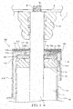
FIG. 1 is a cross-section view of a shock absorber provided with a bump stopper according to a first embodiment of the present invention; -
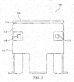
FIG. 2 is a front view of the bump stopper shown inFIG. 1 ; -
FIG. 3 is a bottom view of the bump stopper shown inFIG. 1 ; -
FIG. 4A is a bottom view of a collar shown inFIGS. 1 and3 ; -
FIG. 4B is a bottom view of a cap shown inFIGS. 1 and3 ; -
FIG. 4C is a bottom view of a stopper shown inFIGS. 1 and3 ; -
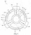
FIG. 5 is a bottom view of a bump stopper according to an alternative embodiment of the first embodiment; -
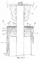
FIG. 6 is a cross-section view of the shock absorber shown inFIG. 1 , and illustrates a state in which the shock absorber is contracted; -
FIG. 7 is a cross-section view of a shock absorber provided with a bump stopper according to a second embodiment of the present invention; -
FIG. 8 is a bottom view of the bump stopper shown inFIG. 7 ; -
FIG. 9 is a cross-section view along line IX-IX shown inFIG. 8 ; -
FIG. 10 is a cross-section view of a shock absorber provided with a bump stopper according to a third embodiment of the present invention; and -
FIG. 11 is a bottom view of the bump stopper shown inFIG. 10 . - Embodiments of the present invention will now be explained below referring to the drawings. Herein, a hydraulic shock absorber in which hydraulic oil is used as a working fluid shall be explained, but other fluids such as a working water may also be used as the working fluid.
- First, referring to
FIGS. 1 to 4C , abump stopper 100 according to a first embodiment of the present invention and ashock absorber 1 equipped with thebump stopper 100 will be explained. Theshock absorber 1 is provided, for example, between avehicle body 5 and a wheel shaft (not illustrated) of a vehicle, and generates a damping force to suppress vibrations of thevehicle body 5. - As shown in
FIG. 1 , theshock absorber 1 includes acylinder 10 in which hydraulic oil is sealed, and apiston rod 30 inserted into thecylinder 10 such that thepiston rod 30 can move into and out of thecylinder 10. A piston (not illustrated) is slidably accommodated in thecylinder 10, and one end of thepiston rod 30 is connected to the piston. The inside of thecylinder 10 is partitioned by the piston into an extension-side chamber 11 and a contraction-side chamber (not illustrated). - The
cylinder 10 includes the following: an approximatelycylindrical tube 12; arod guide 13 provided to one end of thetube 12; and anoil seal 14. Therod guide 13 and theoil seal 14 are fixed to thetube 12 by bending the end of thetube 12 toward the inside. - The
rod guide 13 is formed in an annular shape, and abush 15 is provided to the inner periphery of therod guide 13. Thepiston rod 30 is slidably supported by therod guide 13 via thebush 15. - The
oil seal 14 includes anannular base metal 14a, andlips base metal 14a. Thelips base metal 14a by vulcanization adhesion. - The
lip 14b slidingly contacts thepiston rod 30, and prevents hydraulic oil within thecylinder 10 from leaking to the outside. Thelip 14c slidingly contacts thepiston rod 30, and prevents foreign contaminants from flowing into thecylinder 10. - A
male screw 31 is formed on the other end of thepiston rod 30. A nut (not illustrated) threadably engages with themale screw 31 in a state in which themale screw 31 is inserted into ahole 5a of thevehicle body 5, and thereby thepiston rod 30 is fixed to thevehicle body 5. - A bottom member (not illustrated) is attached to the other end of the
tube 12, and the opening of thetube 12 is blocked by the bottom member. A connection part (not illustrated) to be attached to the wheel shaft is provided to the bottom member, and the bottom member (cylinder 10) is connected by the connection part. - The aforementioned piston includes first and second piston passages that allow the extension-
side chamber 11 to communicate the contraction-side chamber. First and second damping valves are provided respectively to the first and second piston passages. - The first damping valve is opened by a pressure difference between the contraction-side chamber and the extension-
side chamber 11 during contraction of the shock absorber 1, and thereby the first damping valve opens the first piston passage and applies resistance to the flow of hydraulic oil moving from the contraction-side chamber to the extension-side chamber 11 via the first piston passage. The first damping valve closes the first piston passage during extension of theshock absorber 1. - The second damping valve is opened by a pressure difference between the extension-
side chamber 11 and the contraction-side chamber during extension of theshock absorber 1, and thereby the second damping valve opens the second piston passage and applies resistance to the flow of hydraulic oil moving from the extension-side chamber 11 to the contraction-side chamber via the second piston passage. The second damping valve closes the second piston passage during contraction of theshock absorber 1. - In this way, the
shock absorber 1 generates a damping force in accordance with the extension/contraction operations to suppress vibrations of thevehicle body 5. - The
shock absorber 1 further includes abump cushion 40 provided to the outer periphery of thepiston rod 30 between thecylinder 10 and thevehicle body 5, and thebump stopper 100 attached to thecylinder 10. - The
bump cushion 40 is made of a contractible material. When thebump cushion 40 abuts thebump stopper 100 and contracts during contraction of theshock absorber 1, shocks generated by the operation of theshock absorber 1 are absorbed. In this way, thebump stopper 100 cooperates with thebump cushion 40 to absorb shocks generated during maximum contraction of theshock absorber 1. - As shown in
FIGS. 1 to 3 , thebump stopper 100 includes the following: acap 110 that covers the top end side of thecylinder 10; astopper 120 that is supported by thecap 110; and acollar 130 that is provided to the inside of thecap 110. - The
cap 110 is provided with a plate-shapedpart 111 having afirst rod hole 112 into which thepiston rod 30 can be inserted, and acylindrical part 115 which can receive the top end side of thecylinder 10. Thefirst rod hole 112 is formed so as to penetrate between a first surface (inner surface) 111a and a second surface (outer surface) 111b of the plate-shapedpart 111. Hereinafter, thefirst rod hole 112 will also be referred to simply as the "rod hole 112". -
FIGS. 4A, 4B, and 4C are bottom surface views of thecollar 130, thecap 110, and thestopper 120, respectively. InFIGS. 4A, 4B, and 4C , thepiston rod 30 is depicted with dot-dash lines. - As shown in
FIG. 4B , therod hole 112 is positioned in approximately the center of the plate-shapedpart 111. The inner peripheral surface of therod hole 112 includes the following: a plurality ofcurved surface parts 112a formed in an arc shape; and a plurality of recessedsurface parts 112b formed so as to be recessed from thecurved surface parts 112a toward the outside of the plate-shapedpart 111.Openings 112c which are approximately rectangular shaped are defined by the recessedsurface parts 112b. - In the present embodiment, each recessed
surface part 112b is formed by three flat surfaces, but each recessedsurface part 112b may be formed by a single curved surface. If each recessedsurface part 112b is formed by a single curved surface, theopenings 112c are defined in an approximately semicircular shape. - The center of each arc-shaped
curved surface part 112a is approximately the same, and the curvature radius of eachcurved surface part 112a is larger than the radius of thepiston rod 30. Therefore, in a state in which thebump stopper 100 is attached to the cylinder 10 (refer toFIG. 1 ), a gap is formed between the inner wall surface of therod hole 112 and thepiston rod 30. - As shown in
FIGS. 1 to 3 , thecylindrical part 115 is formed to be continuous with the plate-shapedpart 111. In a state in which thecylindrical part 115 has received thecylinder 10, theinner surface 111a of the plate-shapedpart 111 opposes the end surface (oil seal 14) of thecylinder 10. - The
cylindrical part 115 has a plurality ofprotrusions 116 that protrude toward the inside. The plurality ofprotrusions 116 are formed by depressing the outer peripheral surface of thecylindrical part 115. In a state in which thecylindrical part 115 has received thecylinder 10, the plurality ofprotrusions 116 abut the outer peripheral surface of thecylinder 10 so as to push open thecylindrical part 115. Therefore, a relatively large force is necessary to pull out thecylinder 10 from thecap 110, and thecap 110 can be prevented from coming off of thecylinder 10. - The
stopper 120 is provided to theouter surface 111b of the plate-shapedpart 111, and is fixed to thecap 110 by projection welding. Thebump cushion 40 is received and stopped by thestopper 120 during contraction of theshock absorber 1. - A circular
second rod hole 121 is formed in approximately the center of the stopper 120 (refer toFIG. 4C ). Thebump stopper 100 is attached to thecylinder 10 in a state in which thepiston rod 30 is inserted into thesecond rod hole 121. - The inner peripheral surface of the
second rod hole 121 of thestopper 120 is positioned more toward the inside than the inner peripheral surface of therod hole 112 of the plate-shapedpart 111. Therefore, the gap between thestopper 120 and thepiston rod 30 is smaller than the gap between the plate-shapedpart 111 and thepiston rod 30. Thus, regardless of the size of therod hole 112 of the plate-shapedpart 111, thebump cushion 40 does not readily enter into the gap between thestopper 120 and thepiston rod 30, and breakage of thebump cushion 40 can be prevented. - Since the
stopper 120 is provided to theouter surface 111b of the plate-shapedpart 111, thestopper 120 is separated from theoil seal 14 in the axial direction of thepiston rod 30. Therefore, even if the gap between thestopper 120 and thepiston rod 30 is narrowed, contact between thestopper 120 and the oil seal 14 (more specifically, thelip 14c) can be prevented. - Since the gap between the plate-shaped
part 111 and thepiston rod 30 is larger than the gap between thestopper 120 and thepiston rod 30, the inner peripheral surface of therod hole 112 of the plate-shapedpart 111 is separated from thelip 14c in the radial direction of thepiston rod 30. Therefore, even if the interval between the plate-shapedpart 111 and thecylinder 10 is narrowed, contact between the plate-shapedpart 111 and thelip 14c can be prevented. - The
collar 130 is provided to theinner surface 111a of the plate-shapedpart 111, and is fixed to thecap 110 by projection welding. In a state in which thebump stopper 100 is attached to thecylinder 10, thecollar 130 opposes thecylinder 10 and separates the plate-shapedpart 111 and thecylinder 10. Therefore, thestopper 120 is sufficiently separated from theoil seal 14, and contact between thestopper 120 and theoil seal 14 can be more reliably prevented. - As shown in
FIGS. 3 and4A , thecollar 130 includes: a plurality ofsupport parts 131 that support the plate-shapedpart 111; and a plurality ofconnection parts 132 that connectadjacent support parts 131. The plurality ofsupport parts 131 are integrated by theconnections parts 132. In other words, thecollar 130 is formed as a single member. Therefore, when attaching thecollar 130 to thecap 110, thecollar 130 can be easily handled. The same effect is achieved in the second and third embodiments to be explained below. - A circular
third rod hole 133 is formed in thecollar 130 by the plurality ofsupport parts 131 and the plurality ofconnection parts 132. Thebump stopper 100 is attached to thecylinder 10 in a state in which thepiston rod 30 is inserted into thethird rod hole 133 of thecollar 130. - The radius of the
third rod hole 133 of thecollar 130 matches the curvature radius of thecurved surface parts 112a of the plate-shapedpart 111, and the inner peripheral surface of thethird rod hole 133 and thecurved surface parts 112a are continuous without any level differences therebetween. Since the gap between the plate-shapedpart 111 and thepiston rod 30 is larger than the gap between thestopper 120 and thepiston rod 30, the inner peripheral surface of thethird rod hole 133, which is continuous with thecurved surface parts 112a of the plate-shapedpart 111 without any level differences therebetween, is sufficiently separated from thelip 14c in the radial direction of thepiston rod 30. Therefore, contact between thecollar 130 and thelip 14c is prevented. - The plurality of
support parts 131 are arranged in a radial manner betweenadjacent openings 112c. Thereby, radial-shapedpassages 140 which communicate with theopenings 112c of therod hole 112 are formed betweenadjacent support parts 131. Thepassages 140 communicate with the outside of thecylindrical part 115 via the gap between the outer peripheral surface of thecylinder 10 and the inner peripheral surface of thecylindrical part 115. - The "outside of the
cylindrical part 115" indicates the spaces excluding the inside of thecylindrical part 115. Specifically, inFIG. 1 , the "outside of thecylindrical part 115" includes the space to the left side of the left end of thecylindrical part 115, the space to the right side of the right end of thecylindrical part 115, the space on the top side of the top end of thecylindrical part 115, and the space on the bottom side of the bottom end of thecylindrical part 115. In the present embodiment, thepassages 140 communicate with the space on the bottom side of the bottom end of thecylindrical part 115 via the gap between the outer peripheral surface of thecylinder 10 and the inner peripheral surface of thecylindrical part 115. - Since the
passages 140 are formed betweenadjacent support parts 131, the passage forming portions of the plate-shapedpart 111 are supported by thesupport parts 131 on both sides, and thus these passage forming portions do not easily deform. Therefore, deformation of the cross-section shape of thepassages 140 can be prevented, and fluid and dust that have flowed into thecap 110 from therod hole 112 of the plate-shapedpart 111 can be more reliably discharged to the outside of thecap 110. - A flow of air is generated around the
bump cushion 40 in accordance with the contraction of thebump cushion 40. Due to this flow of air, air and dust may flow into the gap between the inner peripheral surface of therod hole 112 of the plate-shapedpart 111 and thepiston rod 30. Further, liquid, i.e. water, may flow into the gap between the inner peripheral surface of therod hole 112 of the plate-shapedpart 111 and thepiston rod 30. - In the present embodiment, the
passages 140 allow therod hole 112 of the plate-shapedpart 111 to communicate with the outside of thecylindrical part 115 via the inside of thecylindrical part 115. Therefore, fluid and dust that have flowed into the gap between the inner peripheral surface of therod hole 112 of the plate-shapedpart 111 and thepiston rod 30 is discharged to the outside of thecap 110 via theopenings 112c of therod hole 112 and thepassages 140. - The
connection parts 132 straddle over theopenings 112c of therod hole 112 so as to extend more toward the inside in the radial direction than the recessedsurface parts 112b. Therefore, thepassages 140 communicate with theopenings 112c of therod hole 112. Thus, the flow in thepassages 140 is not blocked by theconnection parts 132, and fluid and dust that flow into thecap 110 from therod hole 112 can be more reliably discharged to the outside of thecap 110. - The
connection parts 132 are not depressed relative to thesupport parts 131, and are formed in a planar shape along thesupport parts 131. Therefore, thecollar 130 is simple. In addition, the collar can be produced easily because it is not necessary to consider a gap between theconnection parts 132 and thestopper 120 so as to avoid contact between theconnection parts 132 and thestopper 120. - The flow passage cross-section of the
passages 140 is larger than the flow passage cross-section in the gap between thestopper 120 and thepiston rod 30. Therefore, fluid and dust that have flowed into thepassages 140 from this gap do not easily stagnate within thepassages 140. Thus, fluid and dust that have flowed into thecap 110 from therod hole 112 can be more reliably discharged to the outside of thecap 110. - In the present embodiment, since the
passages 140 that allow therod hole 112 to communicate with the outside of thecap 110 are formed by thecap 110 and thecollar 130, it is not necessary to form thecap 110 in a complex shape. Therefore, thebump stopper 100 can be formed easily and reductions in the strength of thebump stopper 100 can be prevented. -
FIG. 5 is a bottom view illustrating abump stopper 101 according to an alternative embodiment of the present embodiment. As shown inFIG. 5 , thecircular rod hole 112 is formed in the plate-shapedpart 111. Further, thecollar 130 does not include portions corresponding to the connection parts 132 (refer toFIGS. 3 and4A ), and the plurality ofsupport parts 131 are separated from each other. In thisbump stopper 101 as well, thepassages 140 are formed by thecollar 130 and thecap 110. Therefore, thebump stopper 101 can be formed easily and reductions in the strength of thebump stopper 101 can be prevented. - In the
bump stopper 101, since the plurality ofsupport parts 131 are separated from each other, there are no members such as theconnection parts 132 betweenadjacent support parts 131, and thus the width of thepassages 140 is expanded. Therefore, flow resistance in thepassages 140 can be reduced, and fluid and dust that have flowed into thecap 110 from therod hole 121 can be more reliably discharged to the outside of thecap 110. - Next, the operation of the
shock absorber 1 will be explained. Since thebump stopper 100 cooperates with thebump cushion 40 to absorb shocks only when theshock absorber 1 contracts, herein, only the contraction operation of theshock absorber 1 will be explained. - When the
shock absorber 1 contracts, thebump cushion 40 abuts the bump stopper 100 (refer toFIG. 6 ). Shocks generated during maximum contraction of theshock absorber 1 are absorbed by the contraction of thebump cushion 40. - A flow of air is generated around the
bump cushion 40 in accordance with the contraction of thebump cushion 40. At this time, fluid and dust flow into the gap between the inner peripheral surface of therod hole 112 of the plate-shapedpart 111 and thepiston rod 30. - Fluid and dust that have flowed into the gap between the inner peripheral surface of the
rod hole 112 of the plate-shapedpart 111 and thepiston rod 30 is discharged to the outside of thecap 110 via the passages 140 (the passages indicated by the arrow mark inFIG. 6 ). Therefore, increases in the pressure within thecap 110 and accumulations of dust within thecap 110 can be prevented. - <Second Embodiment>
- Next, referring to
FIGS. 7 to 9 , abump stopper 200 according to a second embodiment of the present invention will be explained. Constituent elements which are the same as those in the first embodiment will be assigned the same reference numerals, and explanations thereof will be omitted. -
FIG. 7 is a cross-section view of ashock absorber 2 provided with thebump stopper 200.FIG. 8 is a bottom view of thebump stopper 200.FIG. 9 is a cross-section view along line IX-IX shown inFIG. 8 . - The
bump stopper 200 includes the following: thecap 110; thestopper 120; and acollar 230 provided to the inside of thecap 110. Thecollar 230 includes a plurality ofsupport parts 131, and a plurality ofconnection parts 232 which connectadjacent support parts 131. - The
connection parts 232 are depressed in the axial direction of thepiston rod 30 relative to thesupport parts 131 so that theconnection parts 232 enter into therod hole 112. Specifically, as shown inFIG. 9 , eachconnection part 232 includesbase parts 232a formed to be continuous with thesupport parts 131, and amiddle part 232b formed to be continuous with thebase parts 232a. Thebase parts 232a are bent toward thestopper 120, and themiddle part 232b contacts thestopper 120. - In the embodiment shown in
FIG. 9 , the thickness of theconnection parts 232 is approximately equal to the thickness of thesupport parts 131, and the depression of theconnection parts 232 is formed by bending thebase parts 232a. Therefore, the connection parts protrude in the axial direction of thepiston rod 30 relative to thesupport parts 131. - The depression of the
connection parts 232 may be formed without bending thebase parts 232a. For example, the depression may be formed by making the thickness of theconnection parts 232 less than the thickness of thesupport parts 131. - In addition to the effects achieved by the
bump stopper 100 according to the first embodiment, thebump stopper 200 also achieves the following effects. - Since the
connection parts 232 are depressed,passages 240 are formed linearly along the end surface of the cylinder 10 (surface of the oil seal 14) between theconnection parts 232 and thecylinder 10 as shown inFIG. 7 . Therefore, flow resistance in thepassages 240 can be reduced, and fluid and dust that have flowed into thecap 110 from therod hole 112 can be more reliably discharged to the outside of thecap 110. The same effects are also achieved in the third embodiment to be explained below. - The
connection parts 232 do not have to contact thestopper 120. Further, theconnection parts 232 may contact the inner wall surface of therod hole 112. - The operation of the
shock absorber 2 is basically the same as that of theshock absorber 1, and thus an explanation thereof will be omitted herein. - Next, referring to
FIGS. 10 and11 , abump stopper 300 according to a third embodiment of the present invention will be explained. Constituent elements which are the same as those in the first and second embodiments will be assigned the same reference numerals, and explanations thereof will be omitted. -
FIG. 10 is a cross-section view of ashock absorber 3 provided with thebump stopper 300.FIG. 11 is a bottom view of thebump stopper 300. - The
bump stopper 300 includes: acap 310; thestopper 120; and acollar 330 provided to the inside of thecap 310. Acircular rod hole 312 is formed in a plate-shapedpart 311 of thecap 310. Thepiston rod 30 can be inserted into therod hole 312. - A
connection part 332 of thecollar 330 is positioned more toward the inside in the radial direction than the circular inner peripheral surface of therod hole 312. In addition, theconnection part 332 is formed to be depressed relative to thesupport parts 131. - If the
connection parts 232 are depressed so as to fit into theopenings 112c as shown inFIG. 9 , a raised part S of the depression is formed in the flow passage cross-section of thepassages 240. Thepassages 240 are narrowed by an amount equivalent to the raised part S. - In the present embodiment, since the
connection part 332 is positioned more toward the inside in the radial direction than the circular inner peripheral surface of therod hole 312, there is no raised part of the depression in the flow passage cross-section of thepassages 340, and the width of thepassages 340 is expanded. Therefore, flow resistance in thepassages 340 can be reduced, and fluid and dust that have flowed into thecap 310 from therod hole 312 can be more reliably discharged to the outside of the cap. - The
connection part 332 of thecollar 330 is formed in an annular shape and includes a third rod hole 333. Thepiston rod 30 can be inserted into the third rod hole 333. The plurality ofsupport parts 131 are disposed on the outer periphery of theannular connection part 332. Thecollar 330 is fixed to thecap 310 by joining theconnection part 332 and the inner peripheral surface of therod hole 312 of the plate-shapedpart 311. - The
connection part 332 is disposed within therod hole 312 of the plate-shapedpart 311. Therefore, theconnection part 332 is not covered by thecap 310. Thus, when thecollar 330 is fixed to thecap 310, theconnection part 332 can be seen from the outside of thecap 310, and theconnection part 332 can be easily joined to the inner peripheral surface of therod hole 312 of the plate-shapedpart 311. - The
connection part 332 may or may not contact thestopper 120. - In addition to the effects achieved by the
bump stoppers bump stopper 300 also achieves the following effects. - Since the
connection part 332 is not covered by thecap 310, when thecollar 330 is fixed to thecap 310, theconnection part 332 can be seen from the outside of thecap 310, and theconnection part 332 can be easily joined to the inner peripheral surface of therod hole 312 of the plate-shapedpart 311. - The operation of the
shock absorber 3 is basically the same as that of theshock absorber 1, and thus an explanation thereof will be omitted herein. - The constitution, operation, and effects of the embodiments of the present invention will now be summarized below.
- In the present embodiments, the
bump stopper shock absorber bump cushion 40. Thebump stopper cap part rod hole piston rod 30 of theshock absorber cylindrical part 115 configured to receive a portion of thecylinder 10 of theshock absorber stopper 120 provided to the plate-shapedpart bump cushion 40; and thecollar part cylinder 10. - In the above constitution, since the
collar part cylinder 10, it is not necessary to form thecap bump stopper - In the present embodiments, in the
bump stopper collar support parts 131 arranged in a radial manner on the plate-shapedpart part passages rod hole cap cylindrical part 115, are formed by thecap collar passages adjacent support parts 131. - In the above constitution, since the
passages adjacent support parts 131, the passage forming portions of the plate-shapedpart support parts 131 on both sides, and thus these passage forming portions do not easily deform. Therefore, deformation of the cross-section shape of thepassages cap rod hole cap - In the present embodiments, in the
bump stopper collar connection parts adjacent support parts 131. - In the above constitution, since the
connection parts adjacent support parts 131, the plurality ofsupport parts 131 are integrated by theconnection parts collar - In the present embodiments, in the
bump stopper 100, therod hole 112 has theopenings 112c, and theconnection parts 132 are positioned more toward the inside in the radial direction than the inner peripheral surface of theopenings 112c and are formed in a planar shape along thesupport parts 131. - In the above constitution, since the
connection parts 132 are formed in a planar shape along thesupport parts 131, thecollar 130 is simple. In addition, thecollar 130 can be produced easily because it is not necessary to produce thecollar 130 in consideration of a gap between theconnection parts 132 and thestopper 120 so as to avoid contact between theconnection parts 132 and thestopper 120. - In the present embodiments, in the
bump stopper 200, therod hole 112 has theopenings 112c, and theconnection parts 232 are positioned more toward the inside in the radial direction than the inner peripheral surface of theopenings 112c and are formed to be depressed relative to thesupport parts 131. - In the above constitution, since the
connection parts 232 are formed to be depressed relative to thesupport parts 131, thepassages 240 are formed linearly along the end surface of thecylinder 10. Therefore, flow resistance in thepassages 240 can be reduced, and fluid and dust that have flowed into thecap 110 from therod hole 112 can be more reliably discharged to the outside of thecap 110. - In the present embodiments, in the
bump stopper 300, therod hole 312 is circular, and theconnection part 332 is positioned more toward the inside in the radial direction than the circular inner peripheral surface of therod hole 312 and is formed to be depressed relative to thesupport parts 131. - In the above constitution, since the
connection part 332 is positioned more toward the inside in the radial direction than the circular inner peripheral surface of therod hole 312, there is no raised part of the depression in the flow passage cross-section of thepassages 340, and the width of thepassages 340 is expanded. Therefore, flow resistance in thepassages 340 can be reduced, and fluid and dust that have flowed into thecap 310 from therod hole 312 can be more reliably discharged to the outside of thecap 310. - In the present embodiments, in the
bump stopper 300, theconnection part 332 is formed in an annular shape and is disposed within therod hole 312 of the plate-shapedpart 311. - In the above constitution, since the
annular connection part 332 is disposed within therod hole 312, theconnection part 332 is not covered by thecap 310. Thus, when thecollar 330 is fixed to thecap 310, theconnection part 332 can be seen from the outside of thecap 310, and theconnection part 332 can be easily joined to the inner wall surface of therod hole 312. - In the present embodiments, in the
bump stopper 101, the plurality ofsupport parts 131 are separated from each other. - In the above constitution, since the plurality of
support parts 131 are separated from each other, there are no members such as theconnection parts 132 betweenadjacent support parts 131, and thus the width of thepassages 140 is expanded. Therefore, flow resistance in thepassages 140 can be reduced, and fluid and dust that have flowed into thecap 110 from therod hole 121 can be more reliably discharged to the outside of thecap 110. - In the present embodiments, the
bump stopper stopper 120 is positioned more toward the inside in the radial direction than the inner peripheral surface of therod hole part - In the above constitution, since the inner peripheral surface of the
stopper 120 is positioned more toward the inside than the inner peripheral surface of therod hole part stopper 120 and thepiston rod 30 is smaller than the gap between the inner peripheral surface of therod hole piston rod 30. Thus, regardless of the size of therod hole bump cushion 40 does not readily enter into the gap between thestopper 120 and thepiston rod 30, and breakage of thebump cushion 40 can be prevented. - In the present embodiments, the
shock absorber bump stopper piston rod 30 inserted into therod hole passages stopper 120 and thepiston rod 30. - In the above constitution, since the flow passage cross-section of the
passages stopper 120 and thepiston rod 30, fluid and dust that have flowed into thepassages passages cap rod hole cap - Embodiments of this invention were described above, but the above embodiments are merely examples of applications of this invention, and the technical scope of this invention is not limited to the specific constitutions of the above embodiments.
- This application claims priority based on Japanese Patent Application No.
2015-227816
Claims (10)
- A bump stopper for absorbing shocks generated during maximum contraction of a shock absorber in cooperation with a bump cushion, the bump stopper comprising:a cap including a plate-shaped part having a rod hole into which a piston rod of the shock absorber is inserted, and a cylindrical part configured to receive a portion of a cylinder of the shock absorber;a stopper provided to the plate-shaped part, the stopper being configured to receive the bump cushion; anda collar provided to the plate-shaped part opposing the cylinder.
- The bump stopper according to claim 1, wherein the collar comprises a plurality of support parts arranged in a radial manner on the plate-shaped part, the plurality of support parts being configured to support the plate-shaped part,
a passage is formed by the cap and the collar, the passage being configured to allow the rod hole to communicate with an outside of the cylindrical part via an inside of the cylindrical part, and
the passage is formed between the adjacent support parts. - The bump stopper according to claim 2, wherein the collar further comprises a connection part configured to connect the adjacent support parts.
- The bump stopper according to claim 3, wherein the rod hole has an opening, and
the connection part is positioned more toward an inside in a radial direction than an inner peripheral surface of the opening, the connection part being formed in a planar shape along the support parts. - The bump stopper according to claim 3, wherein the rod hole has an opening, and
the connection part is positioned more toward an inside in a radial direction than an inner peripheral surface of the opening, the connection part being formed to be depressed relative to the support parts. - The bump stopper according to claim 3, wherein the rod hole is circular, and
the connection part is positioned more toward an inside in an radial direction than a circular inner peripheral surface of the rod hole, the connection part being formed to be depressed relative to the support parts. - The bump stopper according to claim 6, wherein the connection part is formed in an annular shape and is disposed within the rod hole of the plate-shaped part.
- The bump stopper according to claim 2, wherein the plurality of support parts are separated from each other.
- The bump stopper according to claim 1, wherein an inner peripheral surface of the stopper is positioned more toward the inside in the radial direction than the inner peripheral surface of the rod hole of the plate-shaped part.
- A shock absorber comprising:the bump stopper according to claim 2; anda piston rod that is inserted into the rod hole of the plate-shaped part,wherein a flow passage cross-section of the passage is larger than a flow passage cross-section in a gap between the stopper and the piston rod.
Applications Claiming Priority (2)
| Application Number | Priority Date | Filing Date | Title |
|---|---|---|---|
| JP2015227816A JP6616672B2 (en) | 2015-11-20 | 2015-11-20 | Bump stopper and shock absorber |
| PCT/JP2016/077582 WO2017086012A1 (en) | 2015-11-20 | 2016-09-16 | Bump stopper and buffer |
Publications (3)
| Publication Number | Publication Date |
|---|---|
| EP3379102A1 true EP3379102A1 (en) | 2018-09-26 |
| EP3379102A4 EP3379102A4 (en) | 2019-07-10 |
| EP3379102B1 EP3379102B1 (en) | 2025-06-11 |
Family
ID=58718656
Family Applications (1)
| Application Number | Title | Priority Date | Filing Date |
|---|---|---|---|
| EP16866015.7A Active EP3379102B1 (en) | 2015-11-20 | 2016-09-16 | Bump stopper and buffer |
Country Status (6)
| Country | Link |
|---|---|
| US (1) | US10794447B2 (en) |
| EP (1) | EP3379102B1 (en) |
| JP (1) | JP6616672B2 (en) |
| KR (1) | KR102542393B1 (en) |
| CN (2) | CN110836237A (en) |
| WO (1) | WO2017086012A1 (en) |
Families Citing this family (2)
| Publication number | Priority date | Publication date | Assignee | Title |
|---|---|---|---|---|
| US11566679B2 (en) * | 2020-11-03 | 2023-01-31 | DRiV Automotive Inc. | Bumper cap for damper |
| US20240093751A1 (en) * | 2021-02-24 | 2024-03-21 | Hitachi Astemo, Ltd. | Bumper cap and shock absorber |
Family Cites Families (31)
| Publication number | Priority date | Publication date | Assignee | Title |
|---|---|---|---|---|
| US3346272A (en) * | 1965-10-14 | 1967-10-10 | Monroe Auto Equipment Co | Vehicle suspension device |
| DE7834927U1 (en) * | 1978-11-24 | 1979-03-29 | Fichtel & Sachs Ag, 8720 Schweinfurt | Shock absorber or strut with a hollow rubber spring |
| DE2922437A1 (en) * | 1979-06-01 | 1980-12-11 | Fichtel & Sachs Ag | TWO-TUBE VIBRATION DAMPER WITH UNIVERSALLY APPLICABLE PISTON ROD GUIDE |
| US4397452A (en) * | 1980-11-28 | 1983-08-09 | Ford Motor Company | Hydro-mechanical stop for a shock absorber |
| JPS5820739U (en) | 1981-07-31 | 1983-02-08 | 厚木自動車部品株式会社 | Shock absorber bumper rubber stopper cap |
| JPS6071746U (en) * | 1983-10-24 | 1985-05-21 | カヤバ工業株式会社 | Bump stopper of hydraulic shock absorber |
| US4828232A (en) * | 1983-11-14 | 1989-05-09 | General Motors Corporation | Vehicle air suspension strut with compliant cover plate assembly |
| US4724938A (en) * | 1985-12-09 | 1988-02-16 | General Motors Corporation | Method of making and checking the jounce and rebound actions of an hydraulic damper |
| US4795010A (en) * | 1986-04-10 | 1989-01-03 | Tokico Ltd. | Hydraulic damper |
| JPH0523862Y2 (en) * | 1986-04-11 | 1993-06-17 | ||
| US5078370A (en) * | 1990-11-23 | 1992-01-07 | Chrysler Corporation | Upper mount for suspension strut |
| US5667041A (en) * | 1995-11-03 | 1997-09-16 | General Motors Corporation | Suspension strut with hydraulic stop |
| DE19608771A1 (en) * | 1996-03-07 | 1997-04-24 | Fichtel & Sachs Ag | Guide for piston and cylinder unit, especially for shock absorbers |
| JPH09317811A (en) | 1996-05-27 | 1997-12-12 | Kayaba Ind Co Ltd | Bump stopper locking structure in hydraulic shock absorber |
| DE19644239C2 (en) * | 1996-10-24 | 1999-08-19 | Mannesmann Sachs Ag | End cap for a vibration damper |
| JP4230568B2 (en) * | 1998-07-24 | 2009-02-25 | 株式会社ショーワ | Spring seat fixing structure of hydraulic shock absorber |
| US6186486B1 (en) * | 1999-07-30 | 2001-02-13 | Delphi Technologies, Inc. | Jounce bumper plate |
| JP4048083B2 (en) | 2002-06-28 | 2008-02-13 | カヤバ工業株式会社 | Bump stopper |
| DE10325730B4 (en) * | 2003-06-06 | 2006-02-02 | Zf Sachs Ag | Vibration damper for vehicles |
| JP2006144952A (en) * | 2004-11-22 | 2006-06-08 | Kayaba Ind Co Ltd | Buffer |
| JP2006220162A (en) * | 2005-02-08 | 2006-08-24 | Kayaba Ind Co Ltd | Shock absorber |
| JP5000235B2 (en) * | 2006-08-25 | 2012-08-15 | 日産自動車株式会社 | Cylinder device |
| JP5206965B2 (en) * | 2008-01-31 | 2013-06-12 | 日立オートモティブシステムズ株式会社 | Fluid pressure buffer |
| US8991572B2 (en) * | 2009-09-03 | 2015-03-31 | GM Global Technology Operations LLC | Leak-proof damper having self-diagnostic feature |
| JP5783771B2 (en) * | 2011-03-31 | 2015-09-24 | 日立オートモティブシステムズ株式会社 | Shock absorber |
| WO2013061809A1 (en) * | 2011-10-28 | 2013-05-02 | 本田技研工業株式会社 | Mount structure for vehicle damper and mount installation method for vehicle damper |
| CN202468822U (en) * | 2012-02-16 | 2012-10-03 | 浙江万向系统有限公司 | Multi-point fixed integral dustproof cover of shock absorber |
| CN202888055U (en) * | 2012-09-17 | 2013-04-17 | 常熟市通用电器厂有限公司 | Composite buffer |
| KR101371760B1 (en) * | 2012-12-21 | 2014-03-07 | 현대자동차(주) | Shock absorber apparatus |
| JP5799069B2 (en) * | 2013-10-08 | 2015-10-21 | カヤバ工業株式会社 | Shock absorber |
| JP6435741B2 (en) * | 2014-09-22 | 2018-12-12 | トヨタ自動車株式会社 | Bump stopper cap |
-
2015
- 2015-11-20 JP JP2015227816A patent/JP6616672B2/en active Active
-
2016
- 2016-09-16 KR KR1020187015125A patent/KR102542393B1/en active Active
- 2016-09-16 US US15/773,249 patent/US10794447B2/en active Active
- 2016-09-16 CN CN201911120749.9A patent/CN110836237A/en active Pending
- 2016-09-16 CN CN201680064497.0A patent/CN108350974B/en active Active
- 2016-09-16 EP EP16866015.7A patent/EP3379102B1/en active Active
- 2016-09-16 WO PCT/JP2016/077582 patent/WO2017086012A1/en not_active Ceased
Also Published As
| Publication number | Publication date |
|---|---|
| JP6616672B2 (en) | 2019-12-04 |
| CN110836237A (en) | 2020-02-25 |
| KR102542393B1 (en) | 2023-06-09 |
| US10794447B2 (en) | 2020-10-06 |
| CN108350974A (en) | 2018-07-31 |
| CN108350974B (en) | 2020-12-04 |
| WO2017086012A1 (en) | 2017-05-26 |
| KR20180084827A (en) | 2018-07-25 |
| EP3379102B1 (en) | 2025-06-11 |
| US20180320752A1 (en) | 2018-11-08 |
| JP2017096369A (en) | 2017-06-01 |
| EP3379102A4 (en) | 2019-07-10 |
Similar Documents
| Publication | Publication Date | Title |
|---|---|---|
| JP6351746B2 (en) | Shock absorber | |
| JP6335019B2 (en) | Shock absorber | |
| US8109491B2 (en) | Vibration damper with a stop spring | |
| US10794447B2 (en) | Bump stopper and shock absorber | |
| EP3214337B1 (en) | Shock absorber | |
| US10253840B2 (en) | Cylinder apparatus | |
| US8844575B2 (en) | Guiding device for metal bellows | |
| US20090140496A1 (en) | Sealing Device | |
| CN110392788B (en) | accumulator | |
| JP6810603B2 (en) | Cylinder device | |
| JP6838238B2 (en) | Buffer | |
| CN112119239A (en) | Vibration damper with adjustable damping valve | |
| CN110418900B (en) | Pressure accumulator | |
| KR20250140615A (en) | shock absorber, suspension device | |
| JP7805197B2 (en) | Cylinder Device | |
| JP4883279B2 (en) | Cylinder device | |
| JP2007132484A (en) | Oil seal | |
| JP2025025246A (en) | Shock absorber | |
| WO2024154337A1 (en) | Shock absorbing device, and suspension device | |
| WO2016017575A1 (en) | Piston and shock absorber | |
| JP2017187075A (en) | Shock absorber and manufacturing method thereof |
Legal Events
| Date | Code | Title | Description |
|---|---|---|---|
| STAA | Information on the status of an ep patent application or granted ep patent |
Free format text: STATUS: THE INTERNATIONAL PUBLICATION HAS BEEN MADE |
|
| PUAI | Public reference made under article 153(3) epc to a published international application that has entered the european phase |
Free format text: ORIGINAL CODE: 0009012 |
|
| STAA | Information on the status of an ep patent application or granted ep patent |
Free format text: STATUS: REQUEST FOR EXAMINATION WAS MADE |
|
| 17P | Request for examination filed |
Effective date: 20180620 |
|
| AK | Designated contracting states |
Kind code of ref document: A1 Designated state(s): AL AT BE BG CH CY CZ DE DK EE ES FI FR GB GR HR HU IE IS IT LI LT LU LV MC MK MT NL NO PL PT RO RS SE SI SK SM TR |
|
| AX | Request for extension of the european patent |
Extension state: BA ME |
|
| DAV | Request for validation of the european patent (deleted) | ||
| DAX | Request for extension of the european patent (deleted) | ||
| A4 | Supplementary search report drawn up and despatched |
Effective date: 20190606 |
|
| RIC1 | Information provided on ipc code assigned before grant |
Ipc: F16F 9/58 20060101AFI20190531BHEP Ipc: F16F 9/36 20060101ALI20190531BHEP Ipc: F16F 9/32 20060101ALI20190531BHEP |
|
| STAA | Information on the status of an ep patent application or granted ep patent |
Free format text: STATUS: EXAMINATION IS IN PROGRESS |
|
| 17Q | First examination report despatched |
Effective date: 20220511 |
|
| GRAP | Despatch of communication of intention to grant a patent |
Free format text: ORIGINAL CODE: EPIDOSNIGR1 |
|
| STAA | Information on the status of an ep patent application or granted ep patent |
Free format text: STATUS: GRANT OF PATENT IS INTENDED |
|
| INTG | Intention to grant announced |
Effective date: 20250116 |
|
| GRAS | Grant fee paid |
Free format text: ORIGINAL CODE: EPIDOSNIGR3 |
|
| GRAA | (expected) grant |
Free format text: ORIGINAL CODE: 0009210 |
|
| STAA | Information on the status of an ep patent application or granted ep patent |
Free format text: STATUS: THE PATENT HAS BEEN GRANTED |
|
| AK | Designated contracting states |
Kind code of ref document: B1 Designated state(s): AL AT BE BG CH CY CZ DE DK EE ES FI FR GB GR HR HU IE IS IT LI LT LU LV MC MK MT NL NO PL PT RO RS SE SI SK SM TR |
|
| REG | Reference to a national code |
Ref country code: GB Ref legal event code: FG4D |
|
| REG | Reference to a national code |
Ref country code: CH Ref legal event code: EP |
|
| REG | Reference to a national code |
Ref country code: IE Ref legal event code: FG4D |
|
| REG | Reference to a national code |
Ref country code: DE Ref legal event code: R096 Ref document number: 602016092552 Country of ref document: DE |
|
| PG25 | Lapsed in a contracting state [announced via postgrant information from national office to epo] |
Ref country code: ES Free format text: LAPSE BECAUSE OF FAILURE TO SUBMIT A TRANSLATION OF THE DESCRIPTION OR TO PAY THE FEE WITHIN THE PRESCRIBED TIME-LIMIT Effective date: 20250611 Ref country code: FI Free format text: LAPSE BECAUSE OF FAILURE TO SUBMIT A TRANSLATION OF THE DESCRIPTION OR TO PAY THE FEE WITHIN THE PRESCRIBED TIME-LIMIT Effective date: 20250611 |
|
| PGFP | Annual fee paid to national office [announced via postgrant information from national office to epo] |
Ref country code: DE Payment date: 20250923 Year of fee payment: 10 |
|
| REG | Reference to a national code |
Ref country code: LT Ref legal event code: MG9D |
|
| PG25 | Lapsed in a contracting state [announced via postgrant information from national office to epo] |
Ref country code: GR Free format text: LAPSE BECAUSE OF FAILURE TO SUBMIT A TRANSLATION OF THE DESCRIPTION OR TO PAY THE FEE WITHIN THE PRESCRIBED TIME-LIMIT Effective date: 20250912 Ref country code: NO Free format text: LAPSE BECAUSE OF FAILURE TO SUBMIT A TRANSLATION OF THE DESCRIPTION OR TO PAY THE FEE WITHIN THE PRESCRIBED TIME-LIMIT Effective date: 20250911 |
|
| REG | Reference to a national code |
Ref country code: NL Ref legal event code: MP Effective date: 20250611 |
|
| PG25 | Lapsed in a contracting state [announced via postgrant information from national office to epo] |
Ref country code: BG Free format text: LAPSE BECAUSE OF FAILURE TO SUBMIT A TRANSLATION OF THE DESCRIPTION OR TO PAY THE FEE WITHIN THE PRESCRIBED TIME-LIMIT Effective date: 20250611 |
|
| PG25 | Lapsed in a contracting state [announced via postgrant information from national office to epo] |
Ref country code: HR Free format text: LAPSE BECAUSE OF FAILURE TO SUBMIT A TRANSLATION OF THE DESCRIPTION OR TO PAY THE FEE WITHIN THE PRESCRIBED TIME-LIMIT Effective date: 20250611 |
|
| PG25 | Lapsed in a contracting state [announced via postgrant information from national office to epo] |
Ref country code: RS Free format text: LAPSE BECAUSE OF FAILURE TO SUBMIT A TRANSLATION OF THE DESCRIPTION OR TO PAY THE FEE WITHIN THE PRESCRIBED TIME-LIMIT Effective date: 20250911 |
|
| PG25 | Lapsed in a contracting state [announced via postgrant information from national office to epo] |
Ref country code: LV Free format text: LAPSE BECAUSE OF FAILURE TO SUBMIT A TRANSLATION OF THE DESCRIPTION OR TO PAY THE FEE WITHIN THE PRESCRIBED TIME-LIMIT Effective date: 20250611 |
|
| PG25 | Lapsed in a contracting state [announced via postgrant information from national office to epo] |
Ref country code: NL Free format text: LAPSE BECAUSE OF FAILURE TO SUBMIT A TRANSLATION OF THE DESCRIPTION OR TO PAY THE FEE WITHIN THE PRESCRIBED TIME-LIMIT Effective date: 20250611 |
|
| PG25 | Lapsed in a contracting state [announced via postgrant information from national office to epo] |
Ref country code: PT Free format text: LAPSE BECAUSE OF FAILURE TO SUBMIT A TRANSLATION OF THE DESCRIPTION OR TO PAY THE FEE WITHIN THE PRESCRIBED TIME-LIMIT Effective date: 20251013 |
|
| REG | Reference to a national code |
Ref country code: AT Ref legal event code: MK05 Ref document number: 1802483 Country of ref document: AT Kind code of ref document: T Effective date: 20250611 |
|
| PG25 | Lapsed in a contracting state [announced via postgrant information from national office to epo] |
Ref country code: IS Free format text: LAPSE BECAUSE OF FAILURE TO SUBMIT A TRANSLATION OF THE DESCRIPTION OR TO PAY THE FEE WITHIN THE PRESCRIBED TIME-LIMIT Effective date: 20251011 |
|
| PG25 | Lapsed in a contracting state [announced via postgrant information from national office to epo] |
Ref country code: AT Free format text: LAPSE BECAUSE OF FAILURE TO SUBMIT A TRANSLATION OF THE DESCRIPTION OR TO PAY THE FEE WITHIN THE PRESCRIBED TIME-LIMIT Effective date: 20250611 Ref country code: SM Free format text: LAPSE BECAUSE OF FAILURE TO SUBMIT A TRANSLATION OF THE DESCRIPTION OR TO PAY THE FEE WITHIN THE PRESCRIBED TIME-LIMIT Effective date: 20250611 |
|
| PG25 | Lapsed in a contracting state [announced via postgrant information from national office to epo] |
Ref country code: CZ Free format text: LAPSE BECAUSE OF FAILURE TO SUBMIT A TRANSLATION OF THE DESCRIPTION OR TO PAY THE FEE WITHIN THE PRESCRIBED TIME-LIMIT Effective date: 20250611 |
|
| PG25 | Lapsed in a contracting state [announced via postgrant information from national office to epo] |
Ref country code: PL Free format text: LAPSE BECAUSE OF FAILURE TO SUBMIT A TRANSLATION OF THE DESCRIPTION OR TO PAY THE FEE WITHIN THE PRESCRIBED TIME-LIMIT Effective date: 20250611 |
|
| PG25 | Lapsed in a contracting state [announced via postgrant information from national office to epo] |
Ref country code: EE Free format text: LAPSE BECAUSE OF FAILURE TO SUBMIT A TRANSLATION OF THE DESCRIPTION OR TO PAY THE FEE WITHIN THE PRESCRIBED TIME-LIMIT Effective date: 20250611 |
|
| PG25 | Lapsed in a contracting state [announced via postgrant information from national office to epo] |
Ref country code: SK Free format text: LAPSE BECAUSE OF FAILURE TO SUBMIT A TRANSLATION OF THE DESCRIPTION OR TO PAY THE FEE WITHIN THE PRESCRIBED TIME-LIMIT Effective date: 20250611 Ref country code: RO Free format text: LAPSE BECAUSE OF FAILURE TO SUBMIT A TRANSLATION OF THE DESCRIPTION OR TO PAY THE FEE WITHIN THE PRESCRIBED TIME-LIMIT Effective date: 20250611 |
|
| REG | Reference to a national code |
Ref country code: DE Ref legal event code: R097 Ref document number: 602016092552 Country of ref document: DE |
|
| PG25 | Lapsed in a contracting state [announced via postgrant information from national office to epo] |
Ref country code: DK Free format text: LAPSE BECAUSE OF FAILURE TO SUBMIT A TRANSLATION OF THE DESCRIPTION OR TO PAY THE FEE WITHIN THE PRESCRIBED TIME-LIMIT Effective date: 20250611 |
|
| PG25 | Lapsed in a contracting state [announced via postgrant information from national office to epo] |
Ref country code: IT Free format text: LAPSE BECAUSE OF FAILURE TO SUBMIT A TRANSLATION OF THE DESCRIPTION OR TO PAY THE FEE WITHIN THE PRESCRIBED TIME-LIMIT Effective date: 20250611 |
|
| PLBE | No opposition filed within time limit |
Free format text: ORIGINAL CODE: 0009261 |
|
| STAA | Information on the status of an ep patent application or granted ep patent |
Free format text: STATUS: NO OPPOSITION FILED WITHIN TIME LIMIT |
|
| REG | Reference to a national code |
Ref country code: CH Ref legal event code: L10 Free format text: ST27 STATUS EVENT CODE: U-0-0-L10-L00 (AS PROVIDED BY THE NATIONAL OFFICE) Effective date: 20260423 |
|
| REG | Reference to a national code |
Ref country code: CH Ref legal event code: H13 Free format text: ST27 STATUS EVENT CODE: U-0-0-H10-H13 (AS PROVIDED BY THE NATIONAL OFFICE) Effective date: 20260504 |