EP3379050A1 - Internal combustion engine - Google Patents
Internal combustion engine Download PDFInfo
- Publication number
- EP3379050A1 EP3379050A1 EP18162334.9A EP18162334A EP3379050A1 EP 3379050 A1 EP3379050 A1 EP 3379050A1 EP 18162334 A EP18162334 A EP 18162334A EP 3379050 A1 EP3379050 A1 EP 3379050A1
- Authority
- EP
- European Patent Office
- Prior art keywords
- piston
- port
- top surface
- connection surface
- central axis
- Prior art date
- Legal status (The legal status is an assumption and is not a legal conclusion. Google has not performed a legal analysis and makes no representation as to the accuracy of the status listed.)
- Granted
Links
- 238000002485 combustion reaction Methods 0.000 title claims abstract description 28
- 238000010586 diagram Methods 0.000 description 21
- 230000007423 decrease Effects 0.000 description 11
- 239000000446 fuel Substances 0.000 description 4
- 230000012447 hatching Effects 0.000 description 4
- 230000000694 effects Effects 0.000 description 3
- 230000005484 gravity Effects 0.000 description 3
- 230000006866 deterioration Effects 0.000 description 2
- 239000000779 smoke Substances 0.000 description 2
- 230000003247 decreasing effect Effects 0.000 description 1
- 239000006185 dispersion Substances 0.000 description 1
- 239000000463 material Substances 0.000 description 1
- 238000000034 method Methods 0.000 description 1
- 239000000203 mixture Substances 0.000 description 1
Images


Classifications
-
- F—MECHANICAL ENGINEERING; LIGHTING; HEATING; WEAPONS; BLASTING
- F02—COMBUSTION ENGINES; HOT-GAS OR COMBUSTION-PRODUCT ENGINE PLANTS
- F02B—INTERNAL-COMBUSTION PISTON ENGINES; COMBUSTION ENGINES IN GENERAL
- F02B31/00—Modifying induction systems for imparting a rotation to the charge in the cylinder
- F02B31/02—Modifying induction systems for imparting a rotation to the charge in the cylinder in engines having inlet valves arranged eccentrically to cylinder axis
-
- F—MECHANICAL ENGINEERING; LIGHTING; HEATING; WEAPONS; BLASTING
- F02—COMBUSTION ENGINES; HOT-GAS OR COMBUSTION-PRODUCT ENGINE PLANTS
- F02F—CYLINDERS, PISTONS OR CASINGS, FOR COMBUSTION ENGINES; ARRANGEMENTS OF SEALINGS IN COMBUSTION ENGINES
- F02F1/00—Cylinders; Cylinder heads
- F02F1/24—Cylinder heads
- F02F1/42—Shape or arrangement of intake or exhaust channels in cylinder heads
- F02F1/4214—Shape or arrangement of intake or exhaust channels in cylinder heads specially adapted for four or more valves per cylinder
-
- F—MECHANICAL ENGINEERING; LIGHTING; HEATING; WEAPONS; BLASTING
- F02—COMBUSTION ENGINES; HOT-GAS OR COMBUSTION-PRODUCT ENGINE PLANTS
- F02F—CYLINDERS, PISTONS OR CASINGS, FOR COMBUSTION ENGINES; ARRANGEMENTS OF SEALINGS IN COMBUSTION ENGINES
- F02F1/00—Cylinders; Cylinder heads
- F02F1/24—Cylinder heads
- F02F1/42—Shape or arrangement of intake or exhaust channels in cylinder heads
- F02F1/4235—Shape or arrangement of intake or exhaust channels in cylinder heads of intake channels
-
- F—MECHANICAL ENGINEERING; LIGHTING; HEATING; WEAPONS; BLASTING
- F02—COMBUSTION ENGINES; HOT-GAS OR COMBUSTION-PRODUCT ENGINE PLANTS
- F02F—CYLINDERS, PISTONS OR CASINGS, FOR COMBUSTION ENGINES; ARRANGEMENTS OF SEALINGS IN COMBUSTION ENGINES
- F02F3/00—Pistons
- F02F3/26—Pistons having combustion chamber in piston head
-
- F—MECHANICAL ENGINEERING; LIGHTING; HEATING; WEAPONS; BLASTING
- F02—COMBUSTION ENGINES; HOT-GAS OR COMBUSTION-PRODUCT ENGINE PLANTS
- F02B—INTERNAL-COMBUSTION PISTON ENGINES; COMBUSTION ENGINES IN GENERAL
- F02B23/00—Other engines characterised by special shape or construction of combustion chambers to improve operation
- F02B23/08—Other engines characterised by special shape or construction of combustion chambers to improve operation with positive ignition
- F02B23/10—Other engines characterised by special shape or construction of combustion chambers to improve operation with positive ignition with separate admission of air and fuel into cylinder
- F02B2023/106—Tumble flow, i.e. the axis of rotation of the main charge flow motion is horizontal
- F02B2023/107—Reverse tumble flow, e.g. having substantially vertical intake ports
-
- F—MECHANICAL ENGINEERING; LIGHTING; HEATING; WEAPONS; BLASTING
- F02—COMBUSTION ENGINES; HOT-GAS OR COMBUSTION-PRODUCT ENGINE PLANTS
- F02B—INTERNAL-COMBUSTION PISTON ENGINES; COMBUSTION ENGINES IN GENERAL
- F02B23/00—Other engines characterised by special shape or construction of combustion chambers to improve operation
- F02B23/08—Other engines characterised by special shape or construction of combustion chambers to improve operation with positive ignition
- F02B23/10—Other engines characterised by special shape or construction of combustion chambers to improve operation with positive ignition with separate admission of air and fuel into cylinder
- F02B2023/108—Swirl flow, i.e. the axis of rotation of the main charge flow motion is vertical
-
- F—MECHANICAL ENGINEERING; LIGHTING; HEATING; WEAPONS; BLASTING
- F02—COMBUSTION ENGINES; HOT-GAS OR COMBUSTION-PRODUCT ENGINE PLANTS
- F02B—INTERNAL-COMBUSTION PISTON ENGINES; COMBUSTION ENGINES IN GENERAL
- F02B31/00—Modifying induction systems for imparting a rotation to the charge in the cylinder
- F02B2031/006—Modifying induction systems for imparting a rotation to the charge in the cylinder having multiple air intake valves
-
- F—MECHANICAL ENGINEERING; LIGHTING; HEATING; WEAPONS; BLASTING
- F02—COMBUSTION ENGINES; HOT-GAS OR COMBUSTION-PRODUCT ENGINE PLANTS
- F02B—INTERNAL-COMBUSTION PISTON ENGINES; COMBUSTION ENGINES IN GENERAL
- F02B2275/00—Other engines, components or details, not provided for in other groups of this subclass
- F02B2275/48—Tumble motion in gas movement in cylinder
-
- F—MECHANICAL ENGINEERING; LIGHTING; HEATING; WEAPONS; BLASTING
- F02—COMBUSTION ENGINES; HOT-GAS OR COMBUSTION-PRODUCT ENGINE PLANTS
- F02B—INTERNAL-COMBUSTION PISTON ENGINES; COMBUSTION ENGINES IN GENERAL
- F02B23/00—Other engines characterised by special shape or construction of combustion chambers to improve operation
- F02B23/02—Other engines characterised by special shape or construction of combustion chambers to improve operation with compression ignition
- F02B23/06—Other engines characterised by special shape or construction of combustion chambers to improve operation with compression ignition the combustion space being arranged in working piston
- F02B23/0618—Other engines characterised by special shape or construction of combustion chambers to improve operation with compression ignition the combustion space being arranged in working piston having in-cylinder means to influence the charge motion
- F02B23/0624—Swirl flow
-
- F—MECHANICAL ENGINEERING; LIGHTING; HEATING; WEAPONS; BLASTING
- F02—COMBUSTION ENGINES; HOT-GAS OR COMBUSTION-PRODUCT ENGINE PLANTS
- F02F—CYLINDERS, PISTONS OR CASINGS, FOR COMBUSTION ENGINES; ARRANGEMENTS OF SEALINGS IN COMBUSTION ENGINES
- F02F1/00—Cylinders; Cylinder heads
- F02F1/24—Cylinder heads
- F02F2001/244—Arrangement of valve stems in cylinder heads
- F02F2001/245—Arrangement of valve stems in cylinder heads the valve stems being orientated at an angle with the cylinder axis
-
- Y—GENERAL TAGGING OF NEW TECHNOLOGICAL DEVELOPMENTS; GENERAL TAGGING OF CROSS-SECTIONAL TECHNOLOGIES SPANNING OVER SEVERAL SECTIONS OF THE IPC; TECHNICAL SUBJECTS COVERED BY FORMER USPC CROSS-REFERENCE ART COLLECTIONS [XRACs] AND DIGESTS
- Y02—TECHNOLOGIES OR APPLICATIONS FOR MITIGATION OR ADAPTATION AGAINST CLIMATE CHANGE
- Y02T—CLIMATE CHANGE MITIGATION TECHNOLOGIES RELATED TO TRANSPORTATION
- Y02T10/00—Road transport of goods or passengers
- Y02T10/10—Internal combustion engine [ICE] based vehicles
- Y02T10/12—Improving ICE efficiencies
Definitions
- the invention relates to an internal combustion engine.
- a smoke generation amount varies, even at the same swirl intensity, by inclination of the central axis of the swirl with respect to the central axis of the cylinder. It has also been found that the inclination of the central axis of the swirl varies with the intensity of the tumble component and the intensity of the inverse tumble component of intake air flowing into the cylinder and is affected by the shapes of a cylinder head and the cavity as well as the shape of the intake port. It has been found that the combustion state is improved by the inclination of the central axis of the swirl being reduced to the maximum extent possible and the smoke generation amount decreases as a result of the improvement of the combustion state.
- the invention provides an internal combustion engine in which inclination of the central axis of a swirl with respect to the central axis of a cylinder is reduced.
- An aspect of the invention relates to an internal combustion engine including an intake port configured to generate a swirl in a cylinder, an exhaust port, and a piston.
- the piston includes a top surface provided in an upper portion of the piston, a cavity provided from the top surface toward a lower portion of the piston around a central axis of the piston, and a connection surface connecting an inner edge of the top surface and an upper end of a side surface of the cavity to each other, and the connection surface is provided to be closer to a lower portion side of the piston than the top surface.
- An area of the connection surface projected on a plane parallel to the top surface is larger on an intake port side than on an exhaust port side.
- the upper portion of the piston is a part of the piston that is on a cylinder head side.
- the lower portion of the piston is a part of the piston that is on a crankshaft side.
- the inner edge of the top surface is a boundary between the top surface and the connection surface.
- An upper end of a wall surface of the cavity is a boundary between the wall surface of the cavity and the connection surface.
- the top surface is a flat surface provided in the upper portion of the piston (In the present specification, "flat” includes the meaning of "substantially flat”).
- the cavity is a space recessed from the top surface toward the lower portion of the piston. For example, the cavity is a space to which a fuel is injected.
- connection surface is disposed between the inner edge of the top surface and the upper end of the side surface of the cavity.
- the connection surface is a surface connected to the inner edge of the top surface and is a surface provided to be closer to the lower portion side of the piston than the top surface.
- the connection surface may be a curved surface or a flat surface inclined with respect to the top surface.
- a flow of intake air in the cylinder may contain a tumble component and an inverse tumble component.
- the tumble component and the inverse tumble component rotate in opposite directions in the cylinder.
- the tumble component flows from the intake port toward the exhaust port side mainly through the upper portion of the cylinder (that is, the cylinder head side in the cylinder).
- the inverse tumble component flows through the cylinder from the intake port and along the wall surface of the cylinder mainly at an almost vertical angle. Accordingly, the inverse tumble component flows toward the piston at an angle close to a right angle with respect to the top surface of the piston.
- connection surface When the connection surface is projected on a plane parallel to the top surface, the area of the top surface decreases as the projected area of the connection surface on the intake port side increases, and thus the amount of the inverse tumble component colliding with the top surface decreases and the amount of the inverse tumble component colliding with the connection surface increases.
- the intensity of the inverse tumble component is reduced, the inverse tumble component is dispersed, or the inverse tumble component is stagnant on the top surface because the inverse tumble component collides with the piston at an angle close to a right angle.
- the inverse tumble component In a case where the inverse tumble component collides with the connection surface, the inverse tumble component is likely to flow along the connection surface because the inverse tumble component collides with the piston at an angle smaller than a right angle. Accordingly, a reduction in the intensity of the inverse tumble component is suppressed in a case where the projected area of the connection surface on the intake port side is larger. Then, a larger amount of the inverse tumble component collides with the tumble component, and thus the intensity of the tumble component can be reduced by the inverse tumble component. Therefore, inclination of the central axis of the swirl attributable to the tumble component acting on the swirl can be suppressed. In this manner, inclination of the central axis of the swirl with respect to the central axis of the cylinder can be reduced.
- the intake port may include a tangential port and a helical port and the area of the connection surface on the intake port side projected on the plane parallel to the top surface may be larger on a tangential port side than on a helical port side.
- the intensity of the tumble component of intake air flowing in from the tangential port is larger than the intensity of the tumble component of intake air flowing in from the helical port, and thus the intake air flowing in from the tangential port affects the inclination of the central axis of the swirl to a larger extent. Accordingly, a larger amount of the inverse tumble component from the tangential port is capable of colliding with the tumble component by the projected area of the connection surface on the tangential port side being increased, and thus the intensity of the tumble component can be further reduced. As a result, inclination of the central axis of the swirl with respect to the central axis of the cylinder can be reduced.
- the intake port may include a tangential port, and a central axis of the inner edge of the top surface may be misaligned to a tangential port side from the central axis of the piston.
- the projected area of the connection surface on the tangential port side increases, and thus a reduction in the intensity of the inverse tumble component can be suppressed.
- the intensity of the tumble component becomes likely to be reduced by the inverse tumble component.
- inclination of the central axis of the swirl with respect to the central axis of the cylinder can be reduced.
- the shape of the inner edge of the top surface may not be a perfect circle.
- the central axis of the inner edge of the top surface in this case may be replaced with the center of gravity of the inner edge of the top surface.
- the length of a horizontal direction component of the connection surface may be longer on the intake port side than on the exhaust port side.
- the height of the side surface of the cavity may be the same over an entire circumference of the cavity.
- the inclination of the central axis of the swirl with respect to the central axis of the cylinder can be reduced.
- FIG. 1 is a diagram illustrating a schematic configuration of an internal combustion engine 1 according to a first example.
- the internal combustion engine 1 is mounted in, for example, a vehicle.
- a cylinder 2 is formed in a cylinder block 11 of the internal combustion engine 1.
- An intake port 4 and an exhaust port 5 are formed in a cylinder head 12 of the internal combustion engine 1.
- An intake valve 6 is provided in the cylinder 2 side end portion of the intake port 4.
- An exhaust valve 7 is provided in the cylinder 2 side end portion of the exhaust port 5.
- Two intake valves 6 and two exhaust valves 7 are disposed for each cylinder 2. Accordingly, each of the intake port 4 and the exhaust port 5 branches into two. At least one of the two intake ports 4 is formed to generate a swirl.
- the intake port 4 formed to generate the swirl is, for example, a helical port. At least one of the two intake ports 4 is formed to generate a tumble and an inverse tumble.
- the intake port 4 formed to generate the tumble and the inverse tumble is, for example, a tangential port.
- the shape of the intake port 4 is not limited thereto.
- the intake port 4 may have any shape insofar as the intake port 4 generates a swirl, a tumble, and an inverse tumble in the cylinder 2.
- FIG. 2 is a top view of the piston 8 according to the first example.
- FIG. 3 is a cross-sectional view of the piston 8 taken along cutting line III-III of FIG. 2 .
- a top surface 81 of the piston 8 is a surface that is formed in the upper portion of the piston 8 (that is, the cylinder head 12 side of the piston 8) and is a surface that is formed to be orthogonal to a central axis A1 of the piston 8.
- a cavity 82 recessed from the top surface 81 toward the lower portion of the piston 8 is formed around the central axis A1 of the piston 8.
- the cavity 82 is formed by a surface including a bottom surface 82A and a side surface 82B.
- the bottom surface 82A is a surface that is formed to be parallel to the top surface 81.
- the side surface 82B is a surface standing upright from the bottom surface 82A and is a cylindrical surface about the central axis A1.
- a connection surface 83 is formed between the top surface 81 and the cavity 82.
- the connection surface 83 is a surface inclined with respect to the central axis A1 of the piston 8.
- the connection surface 83 is a surface connecting the upper end of the side surface 82B and an inner edge 81A of the top surface 81 to each other.
- the connection surface 83 is a flat surface inclined with respect to the central axis A1 of the piston 8 in FIG. 3
- the connection surface 83 may also be a curved surface instead of the flat surface.
- the shapes of the bottom surface 82A and the side surface 82B are not limited to the shapes illustrated in FIG. 3 .
- the side surface 82B is formed to be parallel to the central axis A1 of the piston 8 in FIG. 3
- the shape of the side surface 82B is not limited thereto and the side surface 82B may also be formed such that the inner diameter of the side surface 82B gradually decreases from the lower end of the side surface 82B toward the upper end of the side surface 82B.
- the side surface 82B in this case may be a curved surface.
- the place in the side surface 82B where the inner diameter of the side surface 82B is smallest may be the upper end of the side surface 82B.
- the bottom surface 82A and the side surface 82B may be gently connected to each other as well.
- the places where the intake valve 6 and the exhaust valve 7 are projected on the piston 8 are indicated by two-dot chain lines in FIG. 2 , the places may also be where the cylinder 2 side end portions of the intake port 4 and the exhaust port 5 are projected.
- the central axis A1 of the piston 8 in FIGS. 2 and 3 is the central axis of the cylinder 2 and the central axis of the cavity 82 as well.
- A2 in FIGS. 2 and 3 is the central axis of the boundary line between the connection surface 83 and the top surface 81.
- A2 will be referred to as the central axis of the connection surface 83.
- the boundary line between the connection surface 83 and the top surface 81 has the shape of a circle about the central axis A2 as illustrated in FIG. 2 .
- the circle may not be a perfect circle.
- the circle may be an ellipse.
- the boundary line may also have any shape other than a circular shape and an elliptical shape. In that case, the center of gravity may be on A2.
- connection surface 83 according to the first example is formed such that the area projected on a plane that is parallel to the top surface 81 is larger on the intake port 4 side (which may also be the intake valve 6 side) than on the exhaust port 5 side (which may also be the exhaust valve 7 side).
- the connection surface 83 that is projected on a plane parallel to the top surface 81 will also be referred to as a "plane of projection” and the area of the connection surface 83 described below will also be referred to as a " projected area”.
- FIG. 4 is a diagram showing a time when the upper portion of the piston 8 according to FIGS. 2 and 3 is projected on a plane parallel to the top surface 81. The area of the part that is indicated by hatching in FIG.
- connection surface on the intake port 4 side refers to the side that includes the intake port 4 when the piston 8 is divided into two with one plane passing through the central axis A1 of the piston 8 such that the piston 8 is separated into the side that includes the intake valve 6 and the side that includes the exhaust valve 7.
- exhaust port 5 side refers to the side that includes the exhaust port 5 when the piston 8 is divided into two with one plane passing through the central axis A1 of the piston 8 such that the piston 8 is separated into the side that includes the intake valve 6 and the side that includes the exhaust valve 7.
- the connection surface on the intake port 4 side will also be referred to as a range close to the intake port 4 and the connection surface on the exhaust port 5 side will also be referred to as a range close to the exhaust port 5.
- the central axis A2 of the connection surface 83 is misaligned (eccentric) to the intake valve 6 side with respect to the central axis A1 of the piston 8.
- the length of the horizontal direction component of the connection surface differs on the intake port 4 side and the exhaust port 5 side to the same extent as the central axis A2 of the connection surface 83 is misaligned to the intake valve 6 side with respect to the central axis A1 of the piston 8.
- the length of the horizontal direction component of the connection surface 83 is relatively short as indicated by L1 on the exhaust valve 7 side and is relatively long as indicated by L2 on the intake valve 6 side.
- a height H1 of the side surface 82B is the same in the entire cavity 82.
- FIG. 5 is a top view of the piston 8 in a case where the central axis A2 of the connection surface 83 is on the central axis A1 of the piston 8.
- FIG. 6 is a cross-sectional view of the piston 8 taken along cutting line VI-VI of FIG. 5 .
- FIG. 7 is a diagram showing a time when the upper portion of the piston 8 according to FIGS. 5 and 6 is projected on a plane parallel to the top surface 81.
- the area of the part that is indicated by hatching in FIG. 7 corresponds to the projected area
- 83A corresponds to the projected area of the connection surface 83 on the intake port 4 side
- 83B corresponds to the projected area of the connection surface 83 on the exhaust port 5 side.
- connection surface 83 has the same projected area on the intake valve 6 side and the exhaust valve 7 side. As illustrated in FIG. 6 , a length L3 of the horizontal direction component of the connection surface 83 on the exhaust valve 7 side is equal to a length L4 of the horizontal direction component of the connection surface 83 on the intake valve 6 side.
- the height H1 of the side surface 82B is the same in the entire cavity 82.
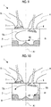
- FIGS. 8 and 9 are diagrams showing the flow of intake air in the piston 8 illustrated in FIGS. 5 and 6 .
- TA represents a tumble component
- TB represents an inverse tumble component.
- the tumble component TA is a flow from the intake port 4 toward the exhaust port 5 side and mainly through the upper portion of the cylinder 2
- the inverse tumble component TB is a flow from the intake port 4 and along the wall surface of the cylinder 2 and the main direction of the inverse tumble component TB is the vertical direction.
- a swirl is mainly a flow around the central axis of the cylinder 2. Since the main direction of the inverse tumble component TB is the vertical direction, the inverse tumble component TB collides with the top surface 81 of the piston 8 at an angle close to a right angle. Accordingly, the intensity of the inverse tumble component TB is likely to be reduced, the inverse tumble component TB is likely to be dispersed, and the inverse tumble component TB is likely to be stagnant on the top surface 81. Then, the tumble component TA becomes relatively stronger and mainly the flow of the tumble component TA remains in the cylinder 2 as illustrated in FIG. 9 . The stronger the flow of the tumble component TA, the more inclined the central axis of the swirl with respect to the central axis A1 of the piston 8. Combustion state deterioration is likely to result from the inclination of the central axis of the swirl.
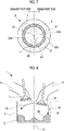
- FIGS. 10 and 11 are diagrams showing the flow of intake air in the piston 8 illustrated in FIGS. 2 and 3 .
- a projected area 83A of the connection surface 83 on the intake port 4 side is large, a larger amount of the inverse tumble component TB collides with the connection surface 83.
- the inverse tumble component TB collides with the connection surface 83 at an angle smaller than a right angle, and thus the inverse tumble component TB is likely to flow along the connection surface 83. Accordingly, a reduction in the intensity of the inverse tumble component TB is suppressed even after the inverse tumble component TB collides with the piston 8.
- the tumble component TA and the inverse tumble component TB collide with each other and counteract each other as illustrated in FIG. 11 .
- the intensity of the tumble component TA decreases, and thus inclination of the central axis of the swirl by the tumble component TA can be suppressed and combustion state deterioration can be suppressed.
- connection surface 83 An overall increase in the projected area of the connection surface 83 is conceivable as well. In that case, however, the intensity of the tumble component is not reduced with ease as the intensity of the tumble component also increases. As the area of the top surface 81 as a whole decreases, a squishing effect decreases. In the first example, in contrast, the projected area of the connection surface 83 on the exhaust port 5 side is relatively small, and thus the area of the top surface 81 on the exhaust port 5 side is large. As a result, the intensity of the tumble component can be reduced and a decline in squishing effect can be suppressed.
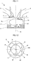
- FIG. 12 is a top view of the piston 8 in which a valve recess is formed.
- FIG. 13 is a diagram showing a time when the upper portion of the piston 8 according to FIG. 12 is projected on a plane parallel to the top surface. The area of the part that is indicated by hatching in FIG. 13 corresponds to the projected area, 83A corresponds to the projected area of the connection surface 83 on the intake port 4 side, and 83B corresponds to the projected area of the connection surface 83 on the exhaust port 5 side.
- An intake valve recess 61 corresponding to each intake valve 6 and an exhaust valve recess 71 corresponding to each exhaust valve 7 are disposed in the piston 8.
- connection surface 83 is formed such that the projected area 83A of the connection surface 83 on the intake port 4 side (which may also be the intake valve 6 side) is larger than the projected area 83B of the connection surface 83 on the exhaust port 5 side (which may also be the exhaust valve 7 side).
- an increase in the projected area of the connection surface 83 results in the same degree of decrease in the area of the top surface 81. Accordingly, it can be said that the top surface 81 and the connection surface 83 are formed such that the area of the top surface 81 is smaller on the intake port 4 side than on the exhaust port 5 side.
- inclination of the central axis of the swirl can be reduced by the projected area of the connection surface 83 being larger on the intake port 4 side (which may also be the intake valve 6 side) than on the exhaust port 5 side (which may also be the exhaust valve 7 side).
- combustion can be carried out well.
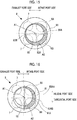
- FIG. 14 is a top view of the piston 8 according to a second example.
- one of the intake ports 4 is a helical port and the other intake port 4 is a tangential port.
- the helical port side intake valve 6 will be referred to as a helical intake valve 6A and the tangential port side intake valve 6 will be referred to as a tangential intake valve 6B.
- the helical port is optional.
- FIG. 15 is a diagram showing a time when the upper portion of the piston 8 according to FIG. 14 is projected on a plane parallel to the top surface 81.
- the area of the part that is indicated by hatching in FIG. 15 corresponds to the projected area
- 83A corresponds to the projected area of the connection surface 83 on the intake port 4 side
- 83B corresponds to the projected area of the connection surface 83 on the exhaust port 5 side.
- the projected area of the connection surface 83 according to the second example is larger on the intake port 4 side (which may also be the intake valve 6 side) than on the exhaust port 5 side (which may also be the exhaust valve 7 side).
- FIG. 16 is a diagram showing a time when the upper portion of the piston 8 according to FIG.
- FIG. 16 is a diagram showing a time when the projected area 83A of the connection surface 83 on the intake port 4 side illustrated in FIG. 15 is further separated into a projected area 83AA on the helical port side and a projected area 83AB on the tangential port side.
- the projected area 83AB of the connection surface 83 on the tangential port side (that is, the tangential intake valve 6B side) is larger than the projected area 83AA of the connection surface 83 on the helical port side (that is, the helical intake valve 6A side).
- the helical port side refers to the side that includes the helical port (the helical intake valve 6A) when the piston 8 is divided into two with one plane passing through the central axis A1 of the piston 8 such that the piston 8 is separated into the side that includes the intake valve 6 and the side that includes the exhaust valve 7 and then the piston 8 is divided into four by the piston 8 being separated into the side that includes the helical intake valve 6A and the side that includes the tangential intake valve 6B with one plane orthogonal to the plane and passing through the central axis A1 of the piston 8.
- the tangential port side refers to the side that includes the tangential port (the tangential intake valve 6B) when the piston 8 is divided into two with one plane passing through the central axis A1 of the piston 8 such that the piston 8 is separated into the side that includes the intake valve 6 and the side that includes the exhaust valve 7 and then the piston 8 is divided into four by the piston 8 being separated into the side that includes the helical intake valve 6A and the side that includes the tangential intake valve 6B with one plane orthogonal to the plane and passing through the central axis A1 of the piston 8.
- the second example is identical to the first example when it comes to the interpretation of the intake port 4 side and the exhaust port 5 side.
- the central axis A2 of the connection surface 83 is misaligned (eccentric) from the central axis A1 of the piston 8 to the tangential intake valve 6B side (that is, the tangential port side). Since the central axis A2 of the connection surface 83 is misaligned with respect to the central axis A1 of the piston 8, the length of the horizontal direction component of the connection surface 83 on the tangential intake valve 6B side is relatively long.
- the height of the side surface 82B is the same in the entire cavity 82 as illustrated in FIG. 3 .
- the inner edge 81A of the top surface 81 may have a shape other than a circular shape. In that case, the center of gravity of the shape may be on A2.
- 20% of the tumble component in the cylinder 2 is from intake air flowing in from the helical port and 80% is from intake air flowing in from the tangential port. Accordingly, a reduction in the intensity of the inverse tumble component from the tangential port needs to be suppressed for a reduction in the intensity of the tumble component.
- the intensity of the inverse tumble component from the tangential port can be increased by the projected area 83AB of the connection surface 83 on the tangential intake valve 6B side being relatively increased, and thus the intensity of the tumble component can be effectively decreased.
- FIG. 17 is a top view of the piston 8 in which a valve recess is formed.
- a helical intake valve recess 61A corresponding to the helical intake valve 6A, a tangential intake valve recess 61B corresponding to the tangential intake valve 6B, and the exhaust valve recess 71 corresponding to each exhaust valve 7 are disposed in the piston 8. Even in this case, the projected area of the connection surface 83 is larger on the intake port 4 side (which may also be the intake valve 6 side) than on the exhaust port 5 side (which may also be the exhaust valve 7 side).
- connection surface 18 is a diagram showing a time when the projected area of the connection surface 83 on the intake port 4 side illustrated in FIG. 17 is separated into the projected area 83AA on the helical port side and the projected area 83AB on the tangential port side.
- the projected area 83AB of the connection surface 83 on the tangential port side (that is, the tangential intake valve 6B side) is larger than the projected area 83AA of the connection surface 83 on the helical port side (that is, the helical intake valve 6A side).
- an increase in the projected area of the connection surface 83 results in the same degree of decrease in the area of the top surface 81. Accordingly, it can be said that the area of the top surface 81 on the tangential intake valve 6B side is relatively small in the second example.
- inclination of the central axis of the swirl can be reduced by the projected area of the connection surface 83 on the tangential intake valve 6B side being relatively increased.
- combustion can be carried out well. Since the projected area of the connection surface 83 on the exhaust port 5 side and the projected area of the connection surface 83 on the helical port side are relatively small, the intensity of the tumble component can be reduced and a decline in squishing effect can be suppressed.
Abstract
Description
- The invention relates to an internal combustion engine.
- When a swirl is generated in a cylinder, mixing between a fuel and air can be promoted, and thus the combustion state of an air-fuel mixture is improved. As a result, fuel economy can be improved. Known in this regard is a technique for adjusting the intensity of the swirl by adjusting the shape of an intake port such as a helical port and a tangential port in an internal combustion engine provided with a piston in which a cavity is formed (refer to, for example, Japanese Unexamined Patent Application Publication No.
2010-270737 JP 2010-270737 A - It has been found that a smoke generation amount varies, even at the same swirl intensity, by inclination of the central axis of the swirl with respect to the central axis of the cylinder. It has also been found that the inclination of the central axis of the swirl varies with the intensity of the tumble component and the intensity of the inverse tumble component of intake air flowing into the cylinder and is affected by the shapes of a cylinder head and the cavity as well as the shape of the intake port. It has been found that the combustion state is improved by the inclination of the central axis of the swirl being reduced to the maximum extent possible and the smoke generation amount decreases as a result of the improvement of the combustion state.
- The invention provides an internal combustion engine in which inclination of the central axis of a swirl with respect to the central axis of a cylinder is reduced.
- An aspect of the invention relates to an internal combustion engine including an intake port configured to generate a swirl in a cylinder, an exhaust port, and a piston. The piston includes a top surface provided in an upper portion of the piston, a cavity provided from the top surface toward a lower portion of the piston around a central axis of the piston, and a connection surface connecting an inner edge of the top surface and an upper end of a side surface of the cavity to each other, and the connection surface is provided to be closer to a lower portion side of the piston than the top surface. An area of the connection surface projected on a plane parallel to the top surface is larger on an intake port side than on an exhaust port side.
- The upper portion of the piston is a part of the piston that is on a cylinder head side. The lower portion of the piston is a part of the piston that is on a crankshaft side. The inner edge of the top surface is a boundary between the top surface and the connection surface. An upper end of a wall surface of the cavity is a boundary between the wall surface of the cavity and the connection surface. The top surface is a flat surface provided in the upper portion of the piston (In the present specification, "flat" includes the meaning of "substantially flat"). The cavity is a space recessed from the top surface toward the lower portion of the piston. For example, the cavity is a space to which a fuel is injected. The connection surface is disposed between the inner edge of the top surface and the upper end of the side surface of the cavity. The connection surface is a surface connected to the inner edge of the top surface and is a surface provided to be closer to the lower portion side of the piston than the top surface. The connection surface may be a curved surface or a flat surface inclined with respect to the top surface.
- A flow of intake air in the cylinder may contain a tumble component and an inverse tumble component. The tumble component and the inverse tumble component rotate in opposite directions in the cylinder. The tumble component flows from the intake port toward the exhaust port side mainly through the upper portion of the cylinder (that is, the cylinder head side in the cylinder). The inverse tumble component flows through the cylinder from the intake port and along the wall surface of the cylinder mainly at an almost vertical angle. Accordingly, the inverse tumble component flows toward the piston at an angle close to a right angle with respect to the top surface of the piston. When the connection surface is projected on a plane parallel to the top surface, the area of the top surface decreases as the projected area of the connection surface on the intake port side increases, and thus the amount of the inverse tumble component colliding with the top surface decreases and the amount of the inverse tumble component colliding with the connection surface increases. In a case where the inverse tumble component collides with the top surface of the piston, the intensity of the inverse tumble component is reduced, the inverse tumble component is dispersed, or the inverse tumble component is stagnant on the top surface because the inverse tumble component collides with the piston at an angle close to a right angle. In a case where the inverse tumble component collides with the connection surface, the inverse tumble component is likely to flow along the connection surface because the inverse tumble component collides with the piston at an angle smaller than a right angle. Accordingly, a reduction in the intensity of the inverse tumble component is suppressed in a case where the projected area of the connection surface on the intake port side is larger. Then, a larger amount of the inverse tumble component collides with the tumble component, and thus the intensity of the tumble component can be reduced by the inverse tumble component. Therefore, inclination of the central axis of the swirl attributable to the tumble component acting on the swirl can be suppressed. In this manner, inclination of the central axis of the swirl with respect to the central axis of the cylinder can be reduced.
- In the internal combustion engine according to the aspect of the invention, the intake port may include a tangential port and a helical port and the area of the connection surface on the intake port side projected on the plane parallel to the top surface may be larger on a tangential port side than on a helical port side.
- In a case where the tangential port and the helical port are formed, the intensity of the tumble component of intake air flowing in from the tangential port is larger than the intensity of the tumble component of intake air flowing in from the helical port, and thus the intake air flowing in from the tangential port affects the inclination of the central axis of the swirl to a larger extent. Accordingly, a larger amount of the inverse tumble component from the tangential port is capable of colliding with the tumble component by the projected area of the connection surface on the tangential port side being increased, and thus the intensity of the tumble component can be further reduced. As a result, inclination of the central axis of the swirl with respect to the central axis of the cylinder can be reduced.
- In the internal combustion engine according to the aspect of the invention, the intake port may include a tangential port, and a central axis of the inner edge of the top surface may be misaligned to a tangential port side from the central axis of the piston.
- In this case, the projected area of the connection surface on the tangential port side increases, and thus a reduction in the intensity of the inverse tumble component can be suppressed. As a result, the intensity of the tumble component becomes likely to be reduced by the inverse tumble component. In other words, inclination of the central axis of the swirl with respect to the central axis of the cylinder can be reduced. The shape of the inner edge of the top surface may not be a perfect circle. The central axis of the inner edge of the top surface in this case may be replaced with the center of gravity of the inner edge of the top surface.
- In the internal combustion engine according to the aspect of the invention, the length of a horizontal direction component of the connection surface may be longer on the intake port side than on the exhaust port side.
- In the internal combustion engine according to the aspect of the invention, the height of the side surface of the cavity may be the same over an entire circumference of the cavity.
- According to the aspect of the invention, the inclination of the central axis of the swirl with respect to the central axis of the cylinder can be reduced.
- Features, advantages, and technical and industrial significance of exemplary embodiments of the invention will be described below with reference to the accompanying drawings, in which like numerals denote like elements, and wherein:
-
FIG. 1 is a diagram illustrating a schematic configuration of an internal combustion engine according to an example; -
FIG. 2 is a top view of a piston according to a first example; -
FIG. 3 is a cross-sectional view of the piston taken along cutting line III-III ofFIG. 2 ; -
FIG. 4 is a diagram showing a time when an upper portion of the piston according toFIGS. 2 and3 is projected on a plane parallel to a top surface; -
FIG. 5 is a top view of the piston in a case where a central axis of a connection surface is on a central axis of the piston; -
FIG. 6 is a cross-sectional view of the piston taken along cutting line VI-VI ofFIG. 5 ; -
FIG. 7 is a diagram showing a time when the upper portion of the piston according toFIGS. 5 and 6 is projected on a plane parallel to the top surface; -
FIG. 8 is a diagram showing a flow of intake air in the piston illustrated inFIGS. 5 and 6 ; -
FIG. 9 is a diagram showing the flow of the intake air in the piston illustrated inFIGS. 5 and 6 ; -
FIG. 10 is a diagram showing the flow of the intake air in the piston illustrated inFIGS. 2 and3 ; -
FIG. 11 is a diagram showing the flow of the intake air in the piston illustrated inFIGS. 2 and3 ; -
FIG. 12 is a top view of a piston in which a valve recess is formed; -
FIG. 13 is a diagram showing a time when an upper portion of the piston according toFIG. 12 is projected on a plane parallel to a top surface; -
FIG. 14 is a top view of a piston according to a second example; -
FIG. 15 is a diagram showing a time when an upper portion of the piston according toFIG. 14 is projected on a plane parallel to a top surface; -
FIG. 16 is a diagram showing a time when a projected area of a connection surface on an intake port side illustrated inFIG. 15 is further separated into a projected area on a helical port side and a projected area on a tangential port side; -
FIG. 17 is a top view of a piston in which a valve recess is formed; and -
FIG. 18 is a diagram showing a time when an upper portion of the piston according toFIG. 17 is projected on a plane parallel to a top surface. - Hereinafter, embodiments of the invention will be illustratively described in detail based on examples with reference to accompanying drawings. The dimensions, materials, shapes, relative dispositions, and so on of the component parts described in the examples do not limit the scope of the invention unless otherwise noted.
-
FIG. 1 is a diagram illustrating a schematic configuration of an internal combustion engine 1 according to a first example. In the first example, illustration of some components is omitted so that the internal combustion engine 1 is shown in a simple way. The internal combustion engine 1 is mounted in, for example, a vehicle. - A
cylinder 2 is formed in acylinder block 11 of the internal combustion engine 1. Anintake port 4 and anexhaust port 5 are formed in acylinder head 12 of the internal combustion engine 1. Anintake valve 6 is provided in thecylinder 2 side end portion of theintake port 4. Anexhaust valve 7 is provided in thecylinder 2 side end portion of theexhaust port 5. Twointake valves 6 and twoexhaust valves 7 are disposed for eachcylinder 2. Accordingly, each of theintake port 4 and theexhaust port 5 branches into two. At least one of the twointake ports 4 is formed to generate a swirl. Theintake port 4 formed to generate the swirl is, for example, a helical port. At least one of the twointake ports 4 is formed to generate a tumble and an inverse tumble. Theintake port 4 formed to generate the tumble and the inverse tumble is, for example, a tangential port. The shape of theintake port 4 is not limited thereto. Theintake port 4 may have any shape insofar as theintake port 4 generates a swirl, a tumble, and an inverse tumble in thecylinder 2. - A
piston 8 is disposed in thecylinder 2.FIG. 2 is a top view of thepiston 8 according to the first example.FIG. 3 is a cross-sectional view of thepiston 8 taken along cutting line III-III ofFIG. 2 . Atop surface 81 of thepiston 8 is a surface that is formed in the upper portion of the piston 8 (that is, thecylinder head 12 side of the piston 8) and is a surface that is formed to be orthogonal to a central axis A1 of thepiston 8. Acavity 82 recessed from thetop surface 81 toward the lower portion of thepiston 8 is formed around the central axis A1 of thepiston 8. Thecavity 82 is formed by a surface including abottom surface 82A and aside surface 82B. Thebottom surface 82A is a surface that is formed to be parallel to thetop surface 81. Theside surface 82B is a surface standing upright from thebottom surface 82A and is a cylindrical surface about the central axis A1. Aconnection surface 83 is formed between thetop surface 81 and thecavity 82. Theconnection surface 83 is a surface inclined with respect to the central axis A1 of thepiston 8. Theconnection surface 83 is a surface connecting the upper end of theside surface 82B and aninner edge 81A of thetop surface 81 to each other. Although theconnection surface 83 is a flat surface inclined with respect to the central axis A1 of thepiston 8 inFIG. 3 , theconnection surface 83 may also be a curved surface instead of the flat surface. The shapes of thebottom surface 82A and theside surface 82B are not limited to the shapes illustrated inFIG. 3 . For example, although theside surface 82B is formed to be parallel to the central axis A1 of thepiston 8 inFIG. 3 , the shape of theside surface 82B is not limited thereto and theside surface 82B may also be formed such that the inner diameter of theside surface 82B gradually decreases from the lower end of theside surface 82B toward the upper end of theside surface 82B. Theside surface 82B in this case may be a curved surface. In a case where theside surface 82B is a curved surface, the place in theside surface 82B where the inner diameter of theside surface 82B is smallest may be the upper end of theside surface 82B. Thebottom surface 82A and theside surface 82B may be gently connected to each other as well. Although the places where theintake valve 6 and theexhaust valve 7 are projected on thepiston 8 are indicated by two-dot chain lines inFIG. 2 , the places may also be where thecylinder 2 side end portions of theintake port 4 and theexhaust port 5 are projected. - The central axis A1 of the
piston 8 inFIGS. 2 and3 is the central axis of thecylinder 2 and the central axis of thecavity 82 as well. A2 inFIGS. 2 and3 is the central axis of the boundary line between theconnection surface 83 and thetop surface 81. In the following description, A2 will be referred to as the central axis of theconnection surface 83. In the first example, the boundary line between theconnection surface 83 and thetop surface 81 has the shape of a circle about the central axis A2 as illustrated inFIG. 2 . However, the circle may not be a perfect circle. For example, the circle may be an ellipse. The boundary line may also have any shape other than a circular shape and an elliptical shape. In that case, the center of gravity may be on A2. - The
connection surface 83 according to the first example is formed such that the area projected on a plane that is parallel to thetop surface 81 is larger on theintake port 4 side (which may also be theintake valve 6 side) than on theexhaust port 5 side (which may also be theexhaust valve 7 side). In the following description, theconnection surface 83 that is projected on a plane parallel to thetop surface 81 will also be referred to as a "plane of projection" and the area of theconnection surface 83 described below will also be referred to as a " projected area".FIG. 4 is a diagram showing a time when the upper portion of thepiston 8 according toFIGS. 2 and3 is projected on a plane parallel to thetop surface 81. The area of the part that is indicated by hatching inFIG. 4 corresponds to the projected area, 83A corresponds to the projected area of theconnection surface 83 on theintake port 4 side, and 83B corresponds to the projected area of theconnection surface 83 on theexhaust port 5 side. Theintake port 4 side refers to the side that includes theintake port 4 when thepiston 8 is divided into two with one plane passing through the central axis A1 of thepiston 8 such that thepiston 8 is separated into the side that includes theintake valve 6 and the side that includes theexhaust valve 7. Likewise, theexhaust port 5 side refers to the side that includes theexhaust port 5 when thepiston 8 is divided into two with one plane passing through the central axis A1 of thepiston 8 such that thepiston 8 is separated into the side that includes theintake valve 6 and the side that includes theexhaust valve 7. In the following description, the connection surface on theintake port 4 side will also be referred to as a range close to theintake port 4 and the connection surface on theexhaust port 5 side will also be referred to as a range close to theexhaust port 5. - It can be said that the central axis A2 of the
connection surface 83 according to the first example is misaligned (eccentric) to theintake valve 6 side with respect to the central axis A1 of thepiston 8. The length of the horizontal direction component of the connection surface differs on theintake port 4 side and theexhaust port 5 side to the same extent as the central axis A2 of theconnection surface 83 is misaligned to theintake valve 6 side with respect to the central axis A1 of thepiston 8. In other words, inFIG. 3 , the length of the horizontal direction component of theconnection surface 83 is relatively short as indicated by L1 on theexhaust valve 7 side and is relatively long as indicated by L2 on theintake valve 6 side. A height H1 of theside surface 82B is the same in theentire cavity 82. -
FIG. 5 is a top view of thepiston 8 in a case where the central axis A2 of theconnection surface 83 is on the central axis A1 of thepiston 8.FIG. 6 is a cross-sectional view of thepiston 8 taken along cutting line VI-VI ofFIG. 5 .FIG. 7 is a diagram showing a time when the upper portion of thepiston 8 according toFIGS. 5 and 6 is projected on a plane parallel to thetop surface 81. The area of the part that is indicated by hatching inFIG. 7 corresponds to the projected area, 83A corresponds to the projected area of theconnection surface 83 on theintake port 4 side, and 83B corresponds to the projected area of theconnection surface 83 on theexhaust port 5 side. In this case, theconnection surface 83 has the same projected area on theintake valve 6 side and theexhaust valve 7 side. As illustrated inFIG. 6 , a length L3 of the horizontal direction component of theconnection surface 83 on theexhaust valve 7 side is equal to a length L4 of the horizontal direction component of theconnection surface 83 on theintake valve 6 side. The height H1 of theside surface 82B is the same in theentire cavity 82. - In the
piston 8 illustrated inFIGS. 2 and3 and thepiston 8 illustrated inFIGS. 5 and 6 , a difference in inverse tumble component intensity occurs due to the different shapes of theconnection surface 83 described above.FIGS. 8 and9 are diagrams showing the flow of intake air in thepiston 8 illustrated inFIGS. 5 and 6 . InFIGS. 8 and9 , TA represents a tumble component and TB represents an inverse tumble component. The tumble component TA is a flow from theintake port 4 toward theexhaust port 5 side and mainly through the upper portion of thecylinder 2, and the inverse tumble component TB is a flow from theintake port 4 and along the wall surface of thecylinder 2 and the main direction of the inverse tumble component TB is the vertical direction. A swirl is mainly a flow around the central axis of thecylinder 2. Since the main direction of the inverse tumble component TB is the vertical direction, the inverse tumble component TB collides with thetop surface 81 of thepiston 8 at an angle close to a right angle. Accordingly, the intensity of the inverse tumble component TB is likely to be reduced, the inverse tumble component TB is likely to be dispersed, and the inverse tumble component TB is likely to be stagnant on thetop surface 81. Then, the tumble component TA becomes relatively stronger and mainly the flow of the tumble component TA remains in thecylinder 2 as illustrated inFIG. 9 . The stronger the flow of the tumble component TA, the more inclined the central axis of the swirl with respect to the central axis A1 of thepiston 8. Combustion state deterioration is likely to result from the inclination of the central axis of the swirl. -
FIGS. 10 and11 are diagrams showing the flow of intake air in thepiston 8 illustrated inFIGS. 2 and3 . In a case where a projectedarea 83A of theconnection surface 83 on theintake port 4 side is large, a larger amount of the inverse tumble component TB collides with theconnection surface 83. In this case, the inverse tumble component TB collides with theconnection surface 83 at an angle smaller than a right angle, and thus the inverse tumble component TB is likely to flow along theconnection surface 83. Accordingly, a reduction in the intensity of the inverse tumble component TB is suppressed even after the inverse tumble component TB collides with thepiston 8. Then, the tumble component TA and the inverse tumble component TB collide with each other and counteract each other as illustrated inFIG. 11 . As a result, the intensity of the tumble component TA decreases, and thus inclination of the central axis of the swirl by the tumble component TA can be suppressed and combustion state deterioration can be suppressed. - An overall increase in the projected area of the
connection surface 83 is conceivable as well. In that case, however, the intensity of the tumble component is not reduced with ease as the intensity of the tumble component also increases. As the area of thetop surface 81 as a whole decreases, a squishing effect decreases. In the first example, in contrast, the projected area of theconnection surface 83 on theexhaust port 5 side is relatively small, and thus the area of thetop surface 81 on theexhaust port 5 side is large. As a result, the intensity of the tumble component can be reduced and a decline in squishing effect can be suppressed. - In some cases, a valve recess is formed in the
piston 8.FIG. 12 is a top view of thepiston 8 in which a valve recess is formed.FIG. 13 is a diagram showing a time when the upper portion of thepiston 8 according toFIG. 12 is projected on a plane parallel to the top surface. The area of the part that is indicated by hatching inFIG. 13 corresponds to the projected area, 83A corresponds to the projected area of theconnection surface 83 on theintake port 4 side, and 83B corresponds to the projected area of theconnection surface 83 on theexhaust port 5 side. Anintake valve recess 61 corresponding to eachintake valve 6 and anexhaust valve recess 71 corresponding to eachexhaust valve 7 are disposed in thepiston 8. Even in this case, theconnection surface 83 is formed such that the projectedarea 83A of theconnection surface 83 on theintake port 4 side (which may also be theintake valve 6 side) is larger than the projectedarea 83B of theconnection surface 83 on theexhaust port 5 side (which may also be theexhaust valve 7 side). Even in a case where the valve recess is formed in thepiston 8 as described above, a reduction in the intensity of the inverse tumble component, dispersion of the inverse tumble component, and stagnation of the inverse tumble component on thetop surface 81 can be suppressed by the area of theconnection surface 83 in the range close to theintake valve 6 being relatively increased. As a result, the intensity of the tumble component TA can be reduced by the inverse tumble component TB. - In the first example, an increase in the projected area of the
connection surface 83 results in the same degree of decrease in the area of thetop surface 81. Accordingly, it can be said that thetop surface 81 and theconnection surface 83 are formed such that the area of thetop surface 81 is smaller on theintake port 4 side than on theexhaust port 5 side. - As described above, according to the first example, inclination of the central axis of the swirl can be reduced by the projected area of the
connection surface 83 being larger on theintake port 4 side (which may also be theintake valve 6 side) than on theexhaust port 5 side (which may also be theexhaust valve 7 side). As a result, combustion can be carried out well. -
FIG. 14 is a top view of thepiston 8 according to a second example. In the second example, one of theintake ports 4 is a helical port and theother intake port 4 is a tangential port. The helical portside intake valve 6 will be referred to as ahelical intake valve 6A and the tangential portside intake valve 6 will be referred to as atangential intake valve 6B. In the second example, the helical port is optional. -
FIG. 15 is a diagram showing a time when the upper portion of thepiston 8 according toFIG. 14 is projected on a plane parallel to thetop surface 81. The area of the part that is indicated by hatching inFIG. 15 corresponds to the projected area, 83A corresponds to the projected area of theconnection surface 83 on theintake port 4 side, and 83B corresponds to the projected area of theconnection surface 83 on theexhaust port 5 side. The projected area of theconnection surface 83 according to the second example is larger on theintake port 4 side (which may also be theintake valve 6 side) than on theexhaust port 5 side (which may also be theexhaust valve 7 side).FIG. 16 is a diagram showing a time when the upper portion of thepiston 8 according toFIG. 14 is projected on a plane parallel to thetop surface 81.FIG. 16 is a diagram showing a time when the projectedarea 83A of theconnection surface 83 on theintake port 4 side illustrated inFIG. 15 is further separated into a projected area 83AA on the helical port side and a projected area 83AB on the tangential port side. In the second example, the projected area 83AB of theconnection surface 83 on the tangential port side (that is, thetangential intake valve 6B side) is larger than the projected area 83AA of theconnection surface 83 on the helical port side (that is, thehelical intake valve 6A side). The helical port side refers to the side that includes the helical port (thehelical intake valve 6A) when thepiston 8 is divided into two with one plane passing through the central axis A1 of thepiston 8 such that thepiston 8 is separated into the side that includes theintake valve 6 and the side that includes theexhaust valve 7 and then thepiston 8 is divided into four by thepiston 8 being separated into the side that includes thehelical intake valve 6A and the side that includes thetangential intake valve 6B with one plane orthogonal to the plane and passing through the central axis A1 of thepiston 8. Likewise, the tangential port side refers to the side that includes the tangential port (thetangential intake valve 6B) when thepiston 8 is divided into two with one plane passing through the central axis A1 of thepiston 8 such that thepiston 8 is separated into the side that includes theintake valve 6 and the side that includes theexhaust valve 7 and then thepiston 8 is divided into four by thepiston 8 being separated into the side that includes thehelical intake valve 6A and the side that includes thetangential intake valve 6B with one plane orthogonal to the plane and passing through the central axis A1 of thepiston 8. The second example is identical to the first example when it comes to the interpretation of theintake port 4 side and theexhaust port 5 side. - It can be said that the central axis A2 of the
connection surface 83 according to the second example is misaligned (eccentric) from the central axis A1 of thepiston 8 to thetangential intake valve 6B side (that is, the tangential port side). Since the central axis A2 of theconnection surface 83 is misaligned with respect to the central axis A1 of thepiston 8, the length of the horizontal direction component of theconnection surface 83 on thetangential intake valve 6B side is relatively long. The height of theside surface 82B is the same in theentire cavity 82 as illustrated inFIG. 3 . Theinner edge 81A of thetop surface 81 may have a shape other than a circular shape. In that case, the center of gravity of the shape may be on A2. - For example, 20% of the tumble component in the
cylinder 2 is from intake air flowing in from the helical port and 80% is from intake air flowing in from the tangential port. Accordingly, a reduction in the intensity of the inverse tumble component from the tangential port needs to be suppressed for a reduction in the intensity of the tumble component. The intensity of the inverse tumble component from the tangential port can be increased by the projected area 83AB of theconnection surface 83 on thetangential intake valve 6B side being relatively increased, and thus the intensity of the tumble component can be effectively decreased. - In some cases, a valve recess is formed in the
piston 8.FIG. 17 is a top view of thepiston 8 in which a valve recess is formed. A helicalintake valve recess 61A corresponding to thehelical intake valve 6A, a tangentialintake valve recess 61B corresponding to thetangential intake valve 6B, and theexhaust valve recess 71 corresponding to eachexhaust valve 7 are disposed in thepiston 8. Even in this case, the projected area of theconnection surface 83 is larger on theintake port 4 side (which may also be theintake valve 6 side) than on theexhaust port 5 side (which may also be theexhaust valve 7 side).FIG. 18 is a diagram showing a time when the projected area of theconnection surface 83 on theintake port 4 side illustrated inFIG. 17 is separated into the projected area 83AA on the helical port side and the projected area 83AB on the tangential port side. The projected area 83AB of theconnection surface 83 on the tangential port side (that is, thetangential intake valve 6B side) is larger than the projected area 83AA of theconnection surface 83 on the helical port side (that is, thehelical intake valve 6A side). Even in a case where the valve recess is formed in thepiston 8 as described above, a reduction in the intensity of the inverse tumble component can be suppressed by the projected area 83AB of theconnection surface 83 on thetangential intake valve 6B side being relatively increased. As a result, the intensity of the tumble component can be reduced by the inverse tumble component. - In the second example, an increase in the projected area of the
connection surface 83 results in the same degree of decrease in the area of thetop surface 81. Accordingly, it can be said that the area of thetop surface 81 on thetangential intake valve 6B side is relatively small in the second example. - As described above, according to the second example, inclination of the central axis of the swirl can be reduced by the projected area of the
connection surface 83 on thetangential intake valve 6B side being relatively increased. As a result, combustion can be carried out well. Since the projected area of theconnection surface 83 on theexhaust port 5 side and the projected area of theconnection surface 83 on the helical port side are relatively small, the intensity of the tumble component can be reduced and a decline in squishing effect can be suppressed.
Claims (5)
- An internal combustion engine (1) comprising:an intake port (4) configured to generate a swirl in a cylinder (2);an exhaust port (5); anda piston (8), wherein:the piston (8) includes a top surface (81) provided in an upper portion of the piston (8), a cavity (82) provided from the top surface (81) toward a lower portion of the piston (8) around a central axis (A1) of the piston (8), and a connection surface (83) connecting an inner edge of the top surface (81) and an upper end of a side surface of the cavity (82) to each other, and the connection surface being provided to be closer to a lower portion side of the piston (8) than the top surface (81); andan area of the connection surface (83) projected on a plane parallel to the top surface (81) is larger on an intake port (4) side than on an exhaust port (5) side.
- The internal combustion engine (1) according to claim 1, wherein:the intake port (4) includes a tangential port and a helical port; andthe area of the connection surface (83) on the intake port (4) side projected on the plane parallel to the top surface (81) is larger on a tangential port side than on a helical port side.
- The internal combustion engine (1) according to claim 1, wherein:the intake port (4) includes a tangential port; anda central axis of the inner edge of the top surface (81) is misaligned to a tangential port side from the central axis (Al) of the piston (8).
- The internal combustion engine (1) according to any one of claims 1 to 3, wherein a length of a horizontal direction component of the connection surface (83) is longer on the intake port (4) side than on the exhaust port (5) side.
- The internal combustion engine (1) according to any one of claims 1 to 4, wherein a height of the side surface of the cavity (82) is the same over an entire circumference of the cavity (82).
Applications Claiming Priority (1)
| Application Number | Priority Date | Filing Date | Title |
|---|---|---|---|
| JP2017055793A JP6604350B2 (en) | 2017-03-22 | 2017-03-22 | Internal combustion engine |
Publications (2)
| Publication Number | Publication Date |
|---|---|
| EP3379050A1 true EP3379050A1 (en) | 2018-09-26 |
| EP3379050B1 EP3379050B1 (en) | 2021-12-08 |
Family
ID=61800286
Family Applications (1)
| Application Number | Title | Priority Date | Filing Date |
|---|---|---|---|
| EP18162334.9A Active EP3379050B1 (en) | 2017-03-22 | 2018-03-16 | Internal combustion engine |
Country Status (3)
| Country | Link |
|---|---|
| US (1) | US20180274434A1 (en) |
| EP (1) | EP3379050B1 (en) |
| JP (1) | JP6604350B2 (en) |
Citations (8)
| Publication number | Priority date | Publication date | Assignee | Title |
|---|---|---|---|---|
| DE19726683A1 (en) * | 1997-06-24 | 1999-01-07 | Iav Gmbh | Combustion engine with direct fuel injection |
| DE19853357A1 (en) * | 1998-11-19 | 2000-05-25 | Daimler Chrysler Ag | Cylinder head for internal combustion engine, has piston trough on curved wall part of which fuel stream arrives tangentially |
| US6223715B1 (en) * | 1998-03-23 | 2001-05-01 | Yamaha Hatsudoki Kabushiki Kaisha | Combustion chamber for direct injected engine |
| US6443122B1 (en) * | 1998-05-14 | 2002-09-03 | Volvo Car Corporation | Internal combustion engine |
| US6443119B1 (en) * | 1998-08-11 | 2002-09-03 | Magneti Marelli France | Piston with active guiding head, and associated combustion chamber |
| JP3826491B2 (en) * | 1997-06-06 | 2006-09-27 | 日産自動車株式会社 | Piston for in-cylinder internal combustion engine |
| JP2010270737A (en) | 2009-05-25 | 2010-12-02 | Toyota Central R&D Labs Inc | Compression ignition type internal combustion engine and unburnt hc reducing method for the same |
| US20160341147A1 (en) * | 2015-05-22 | 2016-11-24 | Caterpillar Motoren Gmbh & Co. Kg | Piston top providing structural unit |
Family Cites Families (6)
| Publication number | Priority date | Publication date | Assignee | Title |
|---|---|---|---|---|
| JPH03202619A (en) * | 1989-12-29 | 1991-09-04 | Mazda Motor Corp | Intake system for multi-valve engine |
| EP1511929A1 (en) * | 2002-06-11 | 2005-03-09 | Wisconsin Alumni Research Foundation | Piston/combustion chamber configurations for enhanced ci engine performance |
| JP4432867B2 (en) * | 2005-09-30 | 2010-03-17 | マツダ株式会社 | Spark ignition engine |
| US10024267B2 (en) * | 2011-12-16 | 2018-07-17 | Toyota Jidosha Kabushiki Kaisha | Combustion chamber structure for internal combustion engine |
| JP5825425B2 (en) * | 2012-03-23 | 2015-12-02 | トヨタ自動車株式会社 | Variable valve operating device for internal combustion engine |
| US20150354494A1 (en) * | 2013-02-20 | 2015-12-10 | Mitsubishi Heavy Industries, Ltd. | Cylinder head and engine |
-
2017
- 2017-03-22 JP JP2017055793A patent/JP6604350B2/en active Active
-
2018
- 2018-03-16 EP EP18162334.9A patent/EP3379050B1/en active Active
- 2018-03-20 US US15/926,468 patent/US20180274434A1/en not_active Abandoned
Patent Citations (8)
| Publication number | Priority date | Publication date | Assignee | Title |
|---|---|---|---|---|
| JP3826491B2 (en) * | 1997-06-06 | 2006-09-27 | 日産自動車株式会社 | Piston for in-cylinder internal combustion engine |
| DE19726683A1 (en) * | 1997-06-24 | 1999-01-07 | Iav Gmbh | Combustion engine with direct fuel injection |
| US6223715B1 (en) * | 1998-03-23 | 2001-05-01 | Yamaha Hatsudoki Kabushiki Kaisha | Combustion chamber for direct injected engine |
| US6443122B1 (en) * | 1998-05-14 | 2002-09-03 | Volvo Car Corporation | Internal combustion engine |
| US6443119B1 (en) * | 1998-08-11 | 2002-09-03 | Magneti Marelli France | Piston with active guiding head, and associated combustion chamber |
| DE19853357A1 (en) * | 1998-11-19 | 2000-05-25 | Daimler Chrysler Ag | Cylinder head for internal combustion engine, has piston trough on curved wall part of which fuel stream arrives tangentially |
| JP2010270737A (en) | 2009-05-25 | 2010-12-02 | Toyota Central R&D Labs Inc | Compression ignition type internal combustion engine and unburnt hc reducing method for the same |
| US20160341147A1 (en) * | 2015-05-22 | 2016-11-24 | Caterpillar Motoren Gmbh & Co. Kg | Piston top providing structural unit |
Also Published As
| Publication number | Publication date |
|---|---|
| US20180274434A1 (en) | 2018-09-27 |
| JP6604350B2 (en) | 2019-11-13 |
| EP3379050B1 (en) | 2021-12-08 |
| JP2018159290A (en) | 2018-10-11 |
Similar Documents
| Publication | Publication Date | Title |
|---|---|---|
| JP4379503B2 (en) | Piston for internal combustion engine | |
| JP5786956B2 (en) | Combustion chamber structure of internal combustion engine | |
| KR101979126B1 (en) | Internal combustion engine | |
| US11326548B2 (en) | Engine | |
| US10815944B2 (en) | Partition plate | |
| EP3379050A1 (en) | Internal combustion engine | |
| US10767551B2 (en) | Intake port structure for internal combustion engine | |
| US9790845B2 (en) | Internal combustion engine | |
| US11346276B2 (en) | Combustion chamber structure for internal combustion engine | |
| US10400720B2 (en) | Partition plate | |
| US10903626B2 (en) | Spark plug for increasing combustion speed of gasoline engine | |
| US10267213B2 (en) | Combustion chamber structure of spark-ignition internal combustion engine | |
| US10648398B2 (en) | Intake structure of internal combustion engine | |
| US10815872B2 (en) | Intake port structure for internal combustion engine | |
| US10711685B2 (en) | Internal combustion engine | |
| US20150330291A1 (en) | Internal combustion engine | |
| EP3260693A1 (en) | Cylinder head and engine | |
| JP2011144811A (en) | Internal combustion engine | |
| JP4760765B2 (en) | Internal combustion engine |
Legal Events
| Date | Code | Title | Description |
|---|---|---|---|
| PUAI | Public reference made under article 153(3) epc to a published international application that has entered the european phase |
Free format text: ORIGINAL CODE: 0009012 |
|
| STAA | Information on the status of an ep patent application or granted ep patent |
Free format text: STATUS: REQUEST FOR EXAMINATION WAS MADE |
|
| 17P | Request for examination filed |
Effective date: 20180316 |
|
| AK | Designated contracting states |
Kind code of ref document: A1 Designated state(s): AL AT BE BG CH CY CZ DE DK EE ES FI FR GB GR HR HU IE IS IT LI LT LU LV MC MK MT NL NO PL PT RO RS SE SI SK SM TR |
|
| AX | Request for extension of the european patent |
Extension state: BA ME |
|
| STAA | Information on the status of an ep patent application or granted ep patent |
Free format text: STATUS: EXAMINATION IS IN PROGRESS |
|
| 17Q | First examination report despatched |
Effective date: 20191024 |
|
| STAA | Information on the status of an ep patent application or granted ep patent |
Free format text: STATUS: EXAMINATION IS IN PROGRESS |
|
| REG | Reference to a national code |
Ref country code: DE Ref legal event code: R079 Ref document number: 602018027761 Country of ref document: DE Free format text: PREVIOUS MAIN CLASS: F02B0023060000 Ipc: F02B0023100000 |
|
| RIC1 | Information provided on ipc code assigned before grant |
Ipc: F02B 23/10 20060101AFI20210331BHEP Ipc: F02B 31/02 20060101ALI20210331BHEP Ipc: F02B 31/00 20060101ALI20210331BHEP Ipc: F02F 3/26 20060101ALI20210331BHEP Ipc: F02B 23/06 20060101ALI20210331BHEP |
|
| GRAP | Despatch of communication of intention to grant a patent |
Free format text: ORIGINAL CODE: EPIDOSNIGR1 |
|
| STAA | Information on the status of an ep patent application or granted ep patent |
Free format text: STATUS: GRANT OF PATENT IS INTENDED |
|
| INTG | Intention to grant announced |
Effective date: 20210708 |
|
| GRAS | Grant fee paid |
Free format text: ORIGINAL CODE: EPIDOSNIGR3 |
|
| GRAA | (expected) grant |
Free format text: ORIGINAL CODE: 0009210 |
|
| STAA | Information on the status of an ep patent application or granted ep patent |
Free format text: STATUS: THE PATENT HAS BEEN GRANTED |
|
| RAP3 | Party data changed (applicant data changed or rights of an application transferred) |
Owner name: TOYOTA JIDOSHA KABUSHIKI KAISHA |
|
| RAP3 | Party data changed (applicant data changed or rights of an application transferred) |
Owner name: TOYOTA JIDOSHA KABUSHIKI KAISHA |
|
| AK | Designated contracting states |
Kind code of ref document: B1 Designated state(s): AL AT BE BG CH CY CZ DE DK EE ES FI FR GB GR HR HU IE IS IT LI LT LU LV MC MK MT NL NO PL PT RO RS SE SI SK SM TR |
|
| REG | Reference to a national code |
Ref country code: GB Ref legal event code: FG4D |
|
| REG | Reference to a national code |
Ref country code: AT Ref legal event code: REF Ref document number: 1453945 Country of ref document: AT Kind code of ref document: T Effective date: 20211215 Ref country code: CH Ref legal event code: EP |
|
| REG | Reference to a national code |
Ref country code: DE Ref legal event code: R096 Ref document number: 602018027761 Country of ref document: DE |
|
| REG | Reference to a national code |
Ref country code: IE Ref legal event code: FG4D |
|
| REG | Reference to a national code |
Ref country code: LT Ref legal event code: MG9D |
|
| REG | Reference to a national code |
Ref country code: NL Ref legal event code: MP Effective date: 20211208 |
|
| PG25 | Lapsed in a contracting state [announced via postgrant information from national office to epo] |
Ref country code: RS Free format text: LAPSE BECAUSE OF FAILURE TO SUBMIT A TRANSLATION OF THE DESCRIPTION OR TO PAY THE FEE WITHIN THE PRESCRIBED TIME-LIMIT Effective date: 20211208 Ref country code: LT Free format text: LAPSE BECAUSE OF FAILURE TO SUBMIT A TRANSLATION OF THE DESCRIPTION OR TO PAY THE FEE WITHIN THE PRESCRIBED TIME-LIMIT Effective date: 20211208 Ref country code: FI Free format text: LAPSE BECAUSE OF FAILURE TO SUBMIT A TRANSLATION OF THE DESCRIPTION OR TO PAY THE FEE WITHIN THE PRESCRIBED TIME-LIMIT Effective date: 20211208 Ref country code: BG Free format text: LAPSE BECAUSE OF FAILURE TO SUBMIT A TRANSLATION OF THE DESCRIPTION OR TO PAY THE FEE WITHIN THE PRESCRIBED TIME-LIMIT Effective date: 20220308 |
|
| REG | Reference to a national code |
Ref country code: AT Ref legal event code: MK05 Ref document number: 1453945 Country of ref document: AT Kind code of ref document: T Effective date: 20211208 |
|
| PG25 | Lapsed in a contracting state [announced via postgrant information from national office to epo] |
Ref country code: SE Free format text: LAPSE BECAUSE OF FAILURE TO SUBMIT A TRANSLATION OF THE DESCRIPTION OR TO PAY THE FEE WITHIN THE PRESCRIBED TIME-LIMIT Effective date: 20211208 Ref country code: NO Free format text: LAPSE BECAUSE OF FAILURE TO SUBMIT A TRANSLATION OF THE DESCRIPTION OR TO PAY THE FEE WITHIN THE PRESCRIBED TIME-LIMIT Effective date: 20220308 Ref country code: LV Free format text: LAPSE BECAUSE OF FAILURE TO SUBMIT A TRANSLATION OF THE DESCRIPTION OR TO PAY THE FEE WITHIN THE PRESCRIBED TIME-LIMIT Effective date: 20211208 Ref country code: HR Free format text: LAPSE BECAUSE OF FAILURE TO SUBMIT A TRANSLATION OF THE DESCRIPTION OR TO PAY THE FEE WITHIN THE PRESCRIBED TIME-LIMIT Effective date: 20211208 Ref country code: GR Free format text: LAPSE BECAUSE OF FAILURE TO SUBMIT A TRANSLATION OF THE DESCRIPTION OR TO PAY THE FEE WITHIN THE PRESCRIBED TIME-LIMIT Effective date: 20220309 Ref country code: ES Free format text: LAPSE BECAUSE OF FAILURE TO SUBMIT A TRANSLATION OF THE DESCRIPTION OR TO PAY THE FEE WITHIN THE PRESCRIBED TIME-LIMIT Effective date: 20211208 |
|
| PGFP | Annual fee paid to national office [announced via postgrant information from national office to epo] |
Ref country code: FR Payment date: 20220209 Year of fee payment: 5 |
|
| PG25 | Lapsed in a contracting state [announced via postgrant information from national office to epo] |
Ref country code: NL Free format text: LAPSE BECAUSE OF FAILURE TO SUBMIT A TRANSLATION OF THE DESCRIPTION OR TO PAY THE FEE WITHIN THE PRESCRIBED TIME-LIMIT Effective date: 20211208 |
|
| PG25 | Lapsed in a contracting state [announced via postgrant information from national office to epo] |
Ref country code: SM Free format text: LAPSE BECAUSE OF FAILURE TO SUBMIT A TRANSLATION OF THE DESCRIPTION OR TO PAY THE FEE WITHIN THE PRESCRIBED TIME-LIMIT Effective date: 20211208 Ref country code: SK Free format text: LAPSE BECAUSE OF FAILURE TO SUBMIT A TRANSLATION OF THE DESCRIPTION OR TO PAY THE FEE WITHIN THE PRESCRIBED TIME-LIMIT Effective date: 20211208 Ref country code: RO Free format text: LAPSE BECAUSE OF FAILURE TO SUBMIT A TRANSLATION OF THE DESCRIPTION OR TO PAY THE FEE WITHIN THE PRESCRIBED TIME-LIMIT Effective date: 20211208 Ref country code: PT Free format text: LAPSE BECAUSE OF FAILURE TO SUBMIT A TRANSLATION OF THE DESCRIPTION OR TO PAY THE FEE WITHIN THE PRESCRIBED TIME-LIMIT Effective date: 20220408 Ref country code: EE Free format text: LAPSE BECAUSE OF FAILURE TO SUBMIT A TRANSLATION OF THE DESCRIPTION OR TO PAY THE FEE WITHIN THE PRESCRIBED TIME-LIMIT Effective date: 20211208 Ref country code: CZ Free format text: LAPSE BECAUSE OF FAILURE TO SUBMIT A TRANSLATION OF THE DESCRIPTION OR TO PAY THE FEE WITHIN THE PRESCRIBED TIME-LIMIT Effective date: 20211208 |
|
| PG25 | Lapsed in a contracting state [announced via postgrant information from national office to epo] |
Ref country code: PL Free format text: LAPSE BECAUSE OF FAILURE TO SUBMIT A TRANSLATION OF THE DESCRIPTION OR TO PAY THE FEE WITHIN THE PRESCRIBED TIME-LIMIT Effective date: 20211208 Ref country code: AT Free format text: LAPSE BECAUSE OF FAILURE TO SUBMIT A TRANSLATION OF THE DESCRIPTION OR TO PAY THE FEE WITHIN THE PRESCRIBED TIME-LIMIT Effective date: 20211208 |
|
| REG | Reference to a national code |
Ref country code: DE Ref legal event code: R097 Ref document number: 602018027761 Country of ref document: DE |
|
| PG25 | Lapsed in a contracting state [announced via postgrant information from national office to epo] |
Ref country code: IS Free format text: LAPSE BECAUSE OF FAILURE TO SUBMIT A TRANSLATION OF THE DESCRIPTION OR TO PAY THE FEE WITHIN THE PRESCRIBED TIME-LIMIT Effective date: 20220408 |
|
| PLBE | No opposition filed within time limit |
Free format text: ORIGINAL CODE: 0009261 |
|
| STAA | Information on the status of an ep patent application or granted ep patent |
Free format text: STATUS: NO OPPOSITION FILED WITHIN TIME LIMIT |
|
| PG25 | Lapsed in a contracting state [announced via postgrant information from national office to epo] |
Ref country code: MC Free format text: LAPSE BECAUSE OF FAILURE TO SUBMIT A TRANSLATION OF THE DESCRIPTION OR TO PAY THE FEE WITHIN THE PRESCRIBED TIME-LIMIT Effective date: 20211208 Ref country code: DK Free format text: LAPSE BECAUSE OF FAILURE TO SUBMIT A TRANSLATION OF THE DESCRIPTION OR TO PAY THE FEE WITHIN THE PRESCRIBED TIME-LIMIT Effective date: 20211208 Ref country code: AL Free format text: LAPSE BECAUSE OF FAILURE TO SUBMIT A TRANSLATION OF THE DESCRIPTION OR TO PAY THE FEE WITHIN THE PRESCRIBED TIME-LIMIT Effective date: 20211208 |
|
| REG | Reference to a national code |
Ref country code: CH Ref legal event code: PL |
|
| 26N | No opposition filed |
Effective date: 20220909 |
|
| GBPC | Gb: european patent ceased through non-payment of renewal fee |
Effective date: 20220316 |
|
| PG25 | Lapsed in a contracting state [announced via postgrant information from national office to epo] |
Ref country code: SI Free format text: LAPSE BECAUSE OF FAILURE TO SUBMIT A TRANSLATION OF THE DESCRIPTION OR TO PAY THE FEE WITHIN THE PRESCRIBED TIME-LIMIT Effective date: 20211208 |
|
| REG | Reference to a national code |
Ref country code: BE Ref legal event code: MM Effective date: 20220331 |
|
| PG25 | Lapsed in a contracting state [announced via postgrant information from national office to epo] |
Ref country code: LU Free format text: LAPSE BECAUSE OF NON-PAYMENT OF DUE FEES Effective date: 20220316 Ref country code: LI Free format text: LAPSE BECAUSE OF NON-PAYMENT OF DUE FEES Effective date: 20220331 Ref country code: IE Free format text: LAPSE BECAUSE OF NON-PAYMENT OF DUE FEES Effective date: 20220316 Ref country code: GB Free format text: LAPSE BECAUSE OF NON-PAYMENT OF DUE FEES Effective date: 20220316 Ref country code: CH Free format text: LAPSE BECAUSE OF NON-PAYMENT OF DUE FEES Effective date: 20220331 |
|
| PG25 | Lapsed in a contracting state [announced via postgrant information from national office to epo] |
Ref country code: BE Free format text: LAPSE BECAUSE OF NON-PAYMENT OF DUE FEES Effective date: 20220331 |
|
| PG25 | Lapsed in a contracting state [announced via postgrant information from national office to epo] |
Ref country code: IT Free format text: LAPSE BECAUSE OF FAILURE TO SUBMIT A TRANSLATION OF THE DESCRIPTION OR TO PAY THE FEE WITHIN THE PRESCRIBED TIME-LIMIT Effective date: 20211208 |
|
| PGFP | Annual fee paid to national office [announced via postgrant information from national office to epo] |
Ref country code: DE Payment date: 20230131 Year of fee payment: 6 |
|
| P01 | Opt-out of the competence of the unified patent court (upc) registered |
Effective date: 20230427 |
|
| REG | Reference to a national code |
Ref country code: DE Ref legal event code: R084 Ref document number: 602018027761 Country of ref document: DE |
|
| PG25 | Lapsed in a contracting state [announced via postgrant information from national office to epo] |
Ref country code: FR Free format text: LAPSE BECAUSE OF NON-PAYMENT OF DUE FEES Effective date: 20230331 |
|
| PG25 | Lapsed in a contracting state [announced via postgrant information from national office to epo] |
Ref country code: HU Free format text: LAPSE BECAUSE OF FAILURE TO SUBMIT A TRANSLATION OF THE DESCRIPTION OR TO PAY THE FEE WITHIN THE PRESCRIBED TIME-LIMIT; INVALID AB INITIO Effective date: 20180316 |