EP3379011A1 - Vented hinge assembly - Google Patents
Vented hinge assembly Download PDFInfo
- Publication number
- EP3379011A1 EP3379011A1 EP18155027.8A EP18155027A EP3379011A1 EP 3379011 A1 EP3379011 A1 EP 3379011A1 EP 18155027 A EP18155027 A EP 18155027A EP 3379011 A1 EP3379011 A1 EP 3379011A1
- Authority
- EP
- European Patent Office
- Prior art keywords
- door
- monument
- knuckle
- piece
- leaf
- Prior art date
- Legal status (The legal status is an assumption and is not a legal conclusion. Google has not performed a legal analysis and makes no representation as to the accuracy of the status listed.)
- Granted
Links
- 230000008878 coupling Effects 0.000 claims description 25
- 238000010168 coupling process Methods 0.000 claims description 25
- 238000005859 coupling reaction Methods 0.000 claims description 25
- 230000008859 change Effects 0.000 description 2
- 230000004048 modification Effects 0.000 description 2
- 238000012986 modification Methods 0.000 description 2
- 230000000295 complement effect Effects 0.000 description 1
- 239000012530 fluid Substances 0.000 description 1
Images


Classifications
-
- E—FIXED CONSTRUCTIONS
- E06—DOORS, WINDOWS, SHUTTERS, OR ROLLER BLINDS IN GENERAL; LADDERS
- E06B—FIXED OR MOVABLE CLOSURES FOR OPENINGS IN BUILDINGS, VEHICLES, FENCES OR LIKE ENCLOSURES IN GENERAL, e.g. DOORS, WINDOWS, BLINDS, GATES
- E06B5/00—Doors, windows, or like closures for special purposes; Border constructions therefor
- E06B5/10—Doors, windows, or like closures for special purposes; Border constructions therefor for protection against air-raid or other war-like action; for other protective purposes
- E06B5/12—Doors, windows, or like closures for special purposes; Border constructions therefor for protection against air-raid or other war-like action; for other protective purposes against air pressure, explosion, or gas
-
- E—FIXED CONSTRUCTIONS
- E05—LOCKS; KEYS; WINDOW OR DOOR FITTINGS; SAFES
- E05D—HINGES OR SUSPENSION DEVICES FOR DOORS, WINDOWS OR WINGS
- E05D3/00—Hinges with pins
- E05D3/02—Hinges with pins with one pin
- E05D3/04—Hinges with pins with one pin engaging three or more parts, e.g. sleeves, movable relatively to one another for connecting two or more wings to another member
-
- B—PERFORMING OPERATIONS; TRANSPORTING
- B64—AIRCRAFT; AVIATION; COSMONAUTICS
- B64C—AEROPLANES; HELICOPTERS
- B64C1/00—Fuselages; Constructional features common to fuselages, wings, stabilising surfaces or the like
- B64C1/14—Windows; Doors; Hatch covers or access panels; Surrounding frame structures; Canopies; Windscreens accessories therefor, e.g. pressure sensors, water deflectors, hinges, seals, handles, latches, windscreen wipers
- B64C1/1407—Doors; surrounding frames
- B64C1/1461—Structures of doors or surrounding frames
-
- E—FIXED CONSTRUCTIONS
- E05—LOCKS; KEYS; WINDOW OR DOOR FITTINGS; SAFES
- E05D—HINGES OR SUSPENSION DEVICES FOR DOORS, WINDOWS OR WINGS
- E05D11/00—Additional features or accessories of hinges
-
- E—FIXED CONSTRUCTIONS
- E05—LOCKS; KEYS; WINDOW OR DOOR FITTINGS; SAFES
- E05D—HINGES OR SUSPENSION DEVICES FOR DOORS, WINDOWS OR WINGS
- E05D5/00—Construction of single parts, e.g. the parts for attachment
- E05D5/02—Parts for attachment, e.g. flaps
-
- E—FIXED CONSTRUCTIONS
- E05—LOCKS; KEYS; WINDOW OR DOOR FITTINGS; SAFES
- E05D—HINGES OR SUSPENSION DEVICES FOR DOORS, WINDOWS OR WINGS
- E05D7/00—Hinges or pivots of special construction
- E05D7/009—Elongate hinges, e.g. piano-hinges
-
- E—FIXED CONSTRUCTIONS
- E05—LOCKS; KEYS; WINDOW OR DOOR FITTINGS; SAFES
- E05D—HINGES OR SUSPENSION DEVICES FOR DOORS, WINDOWS OR WINGS
- E05D5/00—Construction of single parts, e.g. the parts for attachment
- E05D5/02—Parts for attachment, e.g. flaps
- E05D5/04—Flat flaps
-
- E—FIXED CONSTRUCTIONS
- E05—LOCKS; KEYS; WINDOW OR DOOR FITTINGS; SAFES
- E05D—HINGES OR SUSPENSION DEVICES FOR DOORS, WINDOWS OR WINGS
- E05D5/00—Construction of single parts, e.g. the parts for attachment
- E05D5/02—Parts for attachment, e.g. flaps
- E05D5/06—Bent flaps
-
- E—FIXED CONSTRUCTIONS
- E05—LOCKS; KEYS; WINDOW OR DOOR FITTINGS; SAFES
- E05Y—INDEXING SCHEME RELATING TO HINGES OR OTHER SUSPENSION DEVICES FOR DOORS, WINDOWS OR WINGS AND DEVICES FOR MOVING WINGS INTO OPEN OR CLOSED POSITION, CHECKS FOR WINGS AND WING FITTINGS NOT OTHERWISE PROVIDED FOR, CONCERNED WITH THE FUNCTIONING OF THE WING
- E05Y2900/00—Application of doors, windows, wings or fittings thereof
- E05Y2900/50—Application of doors, windows, wings or fittings thereof for vehicles
- E05Y2900/502—Application of doors, windows, wings or fittings thereof for vehicles for aircraft
-
- E—FIXED CONSTRUCTIONS
- E05—LOCKS; KEYS; WINDOW OR DOOR FITTINGS; SAFES
- E05Y—INDEXING SCHEME RELATING TO HINGES OR OTHER SUSPENSION DEVICES FOR DOORS, WINDOWS OR WINGS AND DEVICES FOR MOVING WINGS INTO OPEN OR CLOSED POSITION, CHECKS FOR WINGS AND WING FITTINGS NOT OTHERWISE PROVIDED FOR, CONCERNED WITH THE FUNCTIONING OF THE WING
- E05Y2900/00—Application of doors, windows, wings or fittings thereof
- E05Y2900/50—Application of doors, windows, wings or fittings thereof for vehicles
- E05Y2900/53—Application of doors, windows, wings or fittings thereof for vehicles characterised by the type of wing
- E05Y2900/531—Doors
-
- E—FIXED CONSTRUCTIONS
- E06—DOORS, WINDOWS, SHUTTERS, OR ROLLER BLINDS IN GENERAL; LADDERS
- E06B—FIXED OR MOVABLE CLOSURES FOR OPENINGS IN BUILDINGS, VEHICLES, FENCES OR LIKE ENCLOSURES IN GENERAL, e.g. DOORS, WINDOWS, BLINDS, GATES
- E06B7/00—Special arrangements or measures in connection with doors or windows
- E06B7/02—Special arrangements or measures in connection with doors or windows for providing ventilation, e.g. through double windows; Arrangement of ventilation roses
- E06B7/10—Special arrangements or measures in connection with doors or windows for providing ventilation, e.g. through double windows; Arrangement of ventilation roses by special construction of the frame members
Definitions
- the present disclosure generally relates to hinges and, more particularly, to hinges used in variable pressure environments.
- Hinges are generally known for pivotably attaching a door to a frame.
- a continuous or “piano" hinge may be used.
- the door and hinge may be used in certain environments, such as on-board an aircraft or at industrial plant site, that may potentially experience rapid changes in pressure. Such a rapid pressure change may create a significant pressure difference on opposite sides of the door, which may create forces that push the door open and/or damage the door, hinge, or frame.
- Conventional solutions to this problem include providing vents through the door, which are visible, unattractive, and adds weight and cost to the door assembly, or increasing the structural strength of the components used for the door and frame, which also increases weight and cost.
- a hinge assembly for pivotably attaching a door to a monument.
- the hinge assembly includes a first monument piece including a first knuckle and a monument leaf attached to the first knuckle of the first monument piece and configured for coupling to the monument, and a second monument piece including a first knuckle and a monument leaf attached to the first knuckle of the second monument piece and configured for coupling to the monument, wherein the second monument piece is spaced apart from the first monument piece by a monument piece space.
- a door piece includes an intermediate door knuckle extending across the monument piece space, and a door leaf coupled to the intermediate door knuckle and configured for attachment to the door, and a pin extends through the first knuckle of the first monument piece, the first knuckle of the second monument piece, and the intermediate door knuckle.
- a door assembly includes a door defining a fixed end, a free end, a top end, and a bottom end, and a frame extending around the door and including a monument, a side edge spaced apart from the monument, a top edge extending between the monument and the side edge, and a bottom edge spaced apart from the top edge and extending between the monument and the side edge.
- a hinge assembly pivotably mounts the door to the monument, and includes a first monument piece including a first knuckle and a monument leaf attached to the first knuckle of the first monument piece and configured for coupling to the monument, a second monument piece including a first knuckle and a monument leaf attached to the first knuckle of the second monument piece and configured for coupling to the monument, wherein the second monument piece is spaced apart from the first monument piece by a monument piece space, and a door piece.
- the door piece includes an intermediate door knuckle extending across the monument piece space, a door leaf coupled to the intermediate door knuckle and configured for attachment to the door, the door leaf comprising defining a receptacle configured to receive the fixed end of the door, and a pin extending through the first knuckle of the first monument piece, the first knuckle of the second monument piece, and the intermediate door knuckle.
- a position of the fixed end of the door is adjustable relative to the receptacle to create a side gap between the free end of the door and the side edge of the frame, a top gap between the top end of the door and the top edge of the frame, and a bottom gap between the bottom end of the door and the bottom edge of the frame.
- a door assembly includes a door defining a fixed end, a monument configured to support the door, and a hinge assembly.
- the hinge assembly includes a first monument piece having a first knuckle, a second knuckle spaced apart from the first knuckle, and a monument leaf extending between the first and second knuckles of the first monument piece and configured for coupling to the monument.
- the hinge assembly further includes a second monument piece having a first knuckle, a second knuckle spaced apart from the first knuckle, and a monument leaf extending between the first and second knuckles of the second monument piece and configured for coupling to the monument, wherein the second monument piece is spaced apart from the first monument piece by a monument piece space.
- a door piece of the hinge assembly includes a first door knuckle extending between the first and second knuckles of the first monument piece, a second door knuckle extending between the first and second knuckles of the second monument piece, an intermediate door knuckle disposed between the first and second door knuckles and extending across the monument piece space, and a door leaf coupled to the first door knuckle, second door knuckle, and intermediate door knuckle, and configured for attachment to the fixed end of the door.
- the hinge assembly includes a pin extending through the first and second knuckles of the first monument piece, the first and second knuckles of the second monument piece, the first door knuckle, the second door knuckle, and the intermediate door knuckle.
- a space is formed between the intermediate door knuckle and the monument to define a vent gap through the hinge assembly.
- FIG. 1 illustrates a door assembly 20 constructed according to the present disclosure.
- the door assembly 20 may be provided in an area subject to rapid changes in ambient conditions, such as temperature and/or pressure.
- the area in which the door assembly 20 resides may be stationary, such as in a building or at an industrial plant, or it may be mobile, such as on a vehicle like an aircraft or boat. While examples of the door assembly 20 are described herein in connection with being located on an aircraft that may experience sudden pressure changes, it will be appreciated that the door assembly 20 may be provided in other areas and that may experience sudden changes in different ambient conditions, such as temperature.
- the door assembly 20 generally includes a door 22 joined to a frame 24 by a hinge assembly 26.
- the door 22 may have opposite exterior and interior faces 28, 30 exposed to different environments.
- the exterior face 28 may be exposed to a cabin of an aircraft, while the interior face 30 is exposed to a compartment, such as a closet.
- the hinge assembly 26 creates one or more vent gaps or passages when mounted to the door and monument, as will be discussed in greater detail below, to better balance temperature, pressure, or other imbalances across the door 22 in the event of a sudden change in ambient conditions.
- the door 22 may include a fixed end 32, a free end 34, a top end 36, and a bottom end 38. While the door 22 is illustrated as being quadrangular, it will be appreciated that the door 22 may be formed in other shapes, included triangular shapes, other four-sided shapes, and shapes having five or more sides.
- the frame 24 generally extends around, and provides a support for, the door 22.
- the frame 24 includes a monument 40 that supports the door 22, a side edge 42 spaced apart from the monument 40, a top edge 44 extending between the monument 40 and the side edge 42, and a bottom edge 46 spaced apart from the top edge 44 and extending between the monument 40 and the side edge 42.
- the frame 24 may have a shape that is complementary to the door 22, and therefore may be provided in any of the shapes noted above. Alternatively, in some embodiments, the frame 24 may have a shape that is different than the door 22.
- the hinge assembly 26 pivotably connects the door 22 to the monument 40.
- portions of the hinge assembly 26 configured for attachment to the monument 40 include a first monument piece 50, a second monument piece 52, and a third monument piece 54. While three monument pieces are illustrated, fewer than three or greater than three monument pieces may be used.
- the first monument piece 50 includes a first knuckle 56, a second knuckle 58 spaced apart from the first knuckle 56, and a monument leaf 60 extending between the first and second knuckles 56, 58 of the first monument piece 50.
- the monument leaf 60 is configured for coupling, such as by fasteners, to the monument 40.
- the second monument piece 52 is illustrated as including a first knuckle 62, a second knuckle 64 spaced apart from the first knuckle 62, and a monument leaf 66 extending between the first and second knuckles 62, 64 of the second monument piece 52.
- the monument leaf 66 is also configured for coupling, such as by fasteners, to the monument 40.
- the second monument piece 52 is spaced apart from the first monument piece 50 by a distance defined herein as a first monument piece space 68.
- the third monument piece 54 is similar to the first and second monument pieces 50, 52, and includes a first knuckle 70, a second knuckle 72 spaced apart from the first knuckle 70, and a monument leaf 74 extending between the first and second knuckles 70, 72 of the third monument piece 54.
- the monument leaf 74 is also configured for coupling, such as by fasteners, to the monument 40.
- the third monument piece 54 is spaced apart from the second monument piece by a second monument piece space 76.
- first, second, and third monument pieces 50, 52, 54 is illustrated as having two knuckles, it will be appreciated that a fewer or greater number of knuckles may be provided on each monument piece.
- the hinge assembly 26 further includes a door piece 80 for attachment to the door 22.
- the exemplary door piece 80 includes a first door knuckle 82 extending between the first and second knuckles 56, 58 of the first monument piece 50, a second door knuckle 84 extending between the first and second knuckles 62, 64 of the second monument piece 52, and a third door knuckle 86 extending between the first and second knuckles 70, 72 of the third monument piece 54.
- the door piece 80 also has a first intermediate door knuckle 88 disposed between the first and second door knuckles 84, 84 and extending across the first monument piece space 68, and a second intermediate door knuckle 90 disposed between the second and third door knuckles 84, 86 and extending across the second monument piece space 76. While three door knuckles 82, 84, 86 and two intermediate door knuckles 88, 90 are shown, it will be appreciated that greater or fewer knuckles may be provided on the door piece 80.
- the door piece 80 further includes a door leaf 91 coupled to each of the first, second, third, first intermediate, and second intermediate door knuckles 82, 84, 86, 88, 90 and configured for attachment to the fixed end of the door 22.
- the door leaf 91 extends continuously from the first door knuckle 82 to the second door knuckle 84 to the third door knuckle 86. Additionally, the door leaf 91 may extend substantially an entire length of the door 22, as shown in FIGS. 1 and 2 .
- the door leaf 91 may be particularly configured for attachment to the door 22.
- the door leaf 91 may include a first door leaf leg 92, which is directly coupled to the first, second, and third door knuckles 82, 84, 86, as well as the first and second intermediate door knuckles 88, 90.
- a second door leaf leg 94 extends substantially perpendicular to the first door leaf leg 92.
- the door leaf 91 may further include a third door leaf leg 96 which also extends substantially perpendicular to the first door leaf leg 92 and is spaced apart from the second door leaf leg 94.
- the first door leaf leg 92, second door leaf leg 94, and third door leaf leg 96 define a receptacle 95 configured to receive the fixed end 32 of the door 22.
- the third door leaf leg 96 is shorter than the second door leaf leg 94.
- the hinge assembly 26 further includes a pin 98 for pivotably coupling the first, second, and third monument pieces 50, 52, 54 to the door piece 80.
- each of the knuckles described herein is a hollow, circular member defining a passage through which the pin 98 may pass.
- the pin 98 extends through the first and second knuckles 56, 58 of the first monument piece 50, the first and second knuckles 62, 64 of the second monument piece 52, the first and second knuckles 70, 72 of the third monument piece 54, the first door knuckle 82, the second door knuckle 84, the third door knuckle 86, the first intermediate door knuckle 88, and the second intermediate door knuckle 90.
- the pin 98 With the pin 98 inserted through the knuckles, the pin 98 supports the door piece 80 for rotation relative to the first, second, and third monument pieces 50, 52, 54, thereby to allow the door 22 to pivot relative to the monument 40.
- the hinge assembly 26 creates vents to permit quicker equalization of ambient conditions on opposite sides of the door 22. More specifically, the hinge assembly creates spaces between the door piece 80 and the monument 40 that permit fluid flow through the hinge assembly 26.
- a first vent gap 100 is formed in a space between the first intermediate door knuckle 88 and the monument 40, while a second vent gap 102 is formed in a space between the second intermediate door knuckle 90 and the monument 40.
- the size and configuration of the components of the hinge assembly 26 may be selected to control the size of the first and second vent gaps 100, 102. For example, a vertical length of the first and second vent gaps 100, 102 is affected by the widths of the knuckles provided on the first, second, and third monument pieces 50, 52, 54.
- the hinge assembly 26 of the present disclosure therefore, creates one or more vent gaps that permit quicker equalization of ambient conditions on opposite sides of a door.
- the use of an intermediate door knuckle extending between two spaced apart monument pieces creates a stylish design that is aesthetically pleasing when the door is in a closed position while at the same time creating one or more functional vent gaps.
- the intermediate door knuckle(s) cooperates with the knuckles formed on the monument pieces and the other door knuckles to create the appearance of a continuous, hinge structure that can extend the length of the door while creating the necessary vent gaps
- the illustrated hinge assembly 26 further ensures that desired gaps may be formed around the perimeter of the door, thereby to improve equalization of ambient conditions across the door 22. More specifically, by forming the door piece 80 with the receptacle 95, a position of the fixed end 32 of the door 22 is adjustable relative to the receptacle 95. Accordingly, the door 22 may be positioned to create gaps between the door 22 and the frame 24 around a perimeter of the door 22.
- the door 22 may be positioned to create a side gap 110 between the free end 34 of the door 22 and the side edge 42 of the frame 24, a top gap 112 between the top end 36 of the door 22 and the top edge 44 of the frame 24, and a bottom gap 114 between the bottom end 38 of the door 22 and the bottom edge 46 of the frame 24.
Abstract
Description
- The present disclosure generally relates to hinges and, more particularly, to hinges used in variable pressure environments.
- Hinges are generally known for pivotably attaching a door to a frame. For structural, aesthetic, or other reasons, a continuous or "piano" hinge may be used. The door and hinge may be used in certain environments, such as on-board an aircraft or at industrial plant site, that may potentially experience rapid changes in pressure. Such a rapid pressure change may create a significant pressure difference on opposite sides of the door, which may create forces that push the door open and/or damage the door, hinge, or frame. Conventional solutions to this problem include providing vents through the door, which are visible, unattractive, and adds weight and cost to the door assembly, or increasing the structural strength of the components used for the door and frame, which also increases weight and cost.
- It is with respect to these and other considerations that the disclosure made herein is presented.
- In accordance with one aspect of the present disclosure, a hinge assembly is provided for pivotably attaching a door to a monument. The hinge assembly includes a first monument piece including a first knuckle and a monument leaf attached to the first knuckle of the first monument piece and configured for coupling to the monument, and a second monument piece including a first knuckle and a monument leaf attached to the first knuckle of the second monument piece and configured for coupling to the monument, wherein the second monument piece is spaced apart from the first monument piece by a monument piece space. A door piece includes an intermediate door knuckle extending across the monument piece space, and a door leaf coupled to the intermediate door knuckle and configured for attachment to the door, and a pin extends through the first knuckle of the first monument piece, the first knuckle of the second monument piece, and the intermediate door knuckle. When the hinge assembly is mounted to the door and monument, a space is formed between the intermediate door knuckle and the monument to define a vent gap through the hinge assembly.
- In accordance with another aspect of the present disclosure, a door assembly includes a door defining a fixed end, a free end, a top end, and a bottom end, and a frame extending around the door and including a monument, a side edge spaced apart from the monument, a top edge extending between the monument and the side edge, and a bottom edge spaced apart from the top edge and extending between the monument and the side edge. A hinge assembly pivotably mounts the door to the monument, and includes a first monument piece including a first knuckle and a monument leaf attached to the first knuckle of the first monument piece and configured for coupling to the monument, a second monument piece including a first knuckle and a monument leaf attached to the first knuckle of the second monument piece and configured for coupling to the monument, wherein the second monument piece is spaced apart from the first monument piece by a monument piece space, and a door piece. The door piece includes an intermediate door knuckle extending across the monument piece space, a door leaf coupled to the intermediate door knuckle and configured for attachment to the door, the door leaf comprising defining a receptacle configured to receive the fixed end of the door, and a pin extending through the first knuckle of the first monument piece, the first knuckle of the second monument piece, and the intermediate door knuckle. When the hinge assembly is mounted to the door and monument, a space is formed between the intermediate door knuckle and the monument to define a vent gap through the hinge assembly. Additionally, a position of the fixed end of the door is adjustable relative to the receptacle to create a side gap between the free end of the door and the side edge of the frame, a top gap between the top end of the door and the top edge of the frame, and a bottom gap between the bottom end of the door and the bottom edge of the frame.
- In accordance with a further aspect of the present disclosure, a door assembly includes a door defining a fixed end, a monument configured to support the door, and a hinge assembly. The hinge assembly includes a first monument piece having a first knuckle, a second knuckle spaced apart from the first knuckle, and a monument leaf extending between the first and second knuckles of the first monument piece and configured for coupling to the monument. The hinge assembly further includes a second monument piece having a first knuckle, a second knuckle spaced apart from the first knuckle, and a monument leaf extending between the first and second knuckles of the second monument piece and configured for coupling to the monument, wherein the second monument piece is spaced apart from the first monument piece by a monument piece space. A door piece of the hinge assembly includes a first door knuckle extending between the first and second knuckles of the first monument piece, a second door knuckle extending between the first and second knuckles of the second monument piece, an intermediate door knuckle disposed between the first and second door knuckles and extending across the monument piece space, and a door leaf coupled to the first door knuckle, second door knuckle, and intermediate door knuckle, and configured for attachment to the fixed end of the door. Still further, the hinge assembly includes a pin extending through the first and second knuckles of the first monument piece, the first and second knuckles of the second monument piece, the first door knuckle, the second door knuckle, and the intermediate door knuckle. When the hinge assembly is mounted to the door and monument, a space is formed between the intermediate door knuckle and the monument to define a vent gap through the hinge assembly.
- The features, functions, and advantages that have been discussed can be achieved independently in various embodiments or may be combined in yet other embodiments further details of which can be seen with reference to the following description and drawings.
-
-
FIG. 1 is a side elevation view of a door assembly including a vented hinge, according to the present disclosure. -
FIG. 2 is an enlarged perspective view of a portion of the door assembly ofFIG. 1 . -
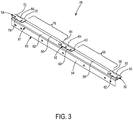
FIG. 3 is a perspective view of a hinge assembly used in the door assembly ofFIG. 1 . -
FIG. 4 is an enlarged plan view of the hinge assembly ofFIG. 3 . -
FIG. 5 is an enlarged plan view, in cross-section, of the door assembly taken along section line 5-5 ofFIG. 1 . - It should be understood that the drawings are not necessarily drawn to scale and that the disclosed embodiments are sometimes illustrated schematically. It is to be further appreciated that the following detailed description is merely exemplary in nature and is not intended to limit the disclosure or the application and uses thereof. Hence, although the present disclosure is, for convenience of explanation, depicted and described as certain illustrative embodiments, it will be appreciated that it can be implemented in various other types of embodiments and in various other systems and environments.
- The following detailed description is of the best currently contemplated modes of carrying out the disclosure. The description is not to be taken in a limiting sense, but is made merely for the purpose of illustrating the general principles of the disclosure, since the scope of the disclosure is best defined by the appended claims.
-
FIG. 1 illustrates adoor assembly 20 constructed according to the present disclosure. Thedoor assembly 20 may be provided in an area subject to rapid changes in ambient conditions, such as temperature and/or pressure. The area in which thedoor assembly 20 resides may be stationary, such as in a building or at an industrial plant, or it may be mobile, such as on a vehicle like an aircraft or boat. While examples of thedoor assembly 20 are described herein in connection with being located on an aircraft that may experience sudden pressure changes, it will be appreciated that thedoor assembly 20 may be provided in other areas and that may experience sudden changes in different ambient conditions, such as temperature. - The
door assembly 20 generally includes adoor 22 joined to aframe 24 by ahinge assembly 26. Thedoor 22 may have opposite exterior andinterior faces exterior face 28 may be exposed to a cabin of an aircraft, while theinterior face 30 is exposed to a compartment, such as a closet. When an ambient condition rapidly changes on one side of thedoor 22, a gradient exists across thedoor 22 that could force the door to move from its intended position, or could damage thedoor assembly 20 and/or its surrounding area. Accordingly, thehinge assembly 26 creates one or more vent gaps or passages when mounted to the door and monument, as will be discussed in greater detail below, to better balance temperature, pressure, or other imbalances across thedoor 22 in the event of a sudden change in ambient conditions. - In greater detail, the
door 22 may include a fixedend 32, afree end 34, atop end 36, and abottom end 38. While thedoor 22 is illustrated as being quadrangular, it will be appreciated that thedoor 22 may be formed in other shapes, included triangular shapes, other four-sided shapes, and shapes having five or more sides. - The
frame 24 generally extends around, and provides a support for, thedoor 22. In the example illustrated inFIG. 1 , theframe 24 includes amonument 40 that supports thedoor 22, aside edge 42 spaced apart from themonument 40, atop edge 44 extending between themonument 40 and theside edge 42, and abottom edge 46 spaced apart from thetop edge 44 and extending between themonument 40 and theside edge 42. Theframe 24 may have a shape that is complementary to thedoor 22, and therefore may be provided in any of the shapes noted above. Alternatively, in some embodiments, theframe 24 may have a shape that is different than thedoor 22. - The
hinge assembly 26 pivotably connects thedoor 22 to themonument 40. As best shown inFIGS. 2-4 , portions of thehinge assembly 26 configured for attachment to themonument 40 include afirst monument piece 50, asecond monument piece 52, and athird monument piece 54. While three monument pieces are illustrated, fewer than three or greater than three monument pieces may be used. - With specific reference to
FIG. 3 , thefirst monument piece 50 includes afirst knuckle 56, asecond knuckle 58 spaced apart from thefirst knuckle 56, and amonument leaf 60 extending between the first andsecond knuckles first monument piece 50. Themonument leaf 60 is configured for coupling, such as by fasteners, to themonument 40. - Similarly, the
second monument piece 52 is illustrated as including afirst knuckle 62, asecond knuckle 64 spaced apart from thefirst knuckle 62, and amonument leaf 66 extending between the first andsecond knuckles second monument piece 52. Themonument leaf 66 is also configured for coupling, such as by fasteners, to themonument 40. As illustrated, thesecond monument piece 52 is spaced apart from thefirst monument piece 50 by a distance defined herein as a firstmonument piece space 68. - Still further, the
third monument piece 54 is similar to the first andsecond monument pieces first knuckle 70, asecond knuckle 72 spaced apart from thefirst knuckle 70, and amonument leaf 74 extending between the first andsecond knuckles third monument piece 54. Themonument leaf 74 is also configured for coupling, such as by fasteners, to themonument 40. Furthermore, thethird monument piece 54 is spaced apart from the second monument piece by a secondmonument piece space 76. - While each of the first, second, and
third monument pieces - The
hinge assembly 26 further includes adoor piece 80 for attachment to thedoor 22. With continued reference toFIGS. 3 and4 , theexemplary door piece 80 includes afirst door knuckle 82 extending between the first andsecond knuckles first monument piece 50, asecond door knuckle 84 extending between the first andsecond knuckles second monument piece 52, and athird door knuckle 86 extending between the first andsecond knuckles third monument piece 54. Thedoor piece 80 also has a firstintermediate door knuckle 88 disposed between the first andsecond door knuckles monument piece space 68, and a secondintermediate door knuckle 90 disposed between the second andthird door knuckles monument piece space 76. While threedoor knuckles intermediate door knuckles door piece 80. - The
door piece 80 further includes adoor leaf 91 coupled to each of the first, second, third, first intermediate, and secondintermediate door knuckles door 22. In the illustrated embodiment, thedoor leaf 91 extends continuously from thefirst door knuckle 82 to thesecond door knuckle 84 to thethird door knuckle 86. Additionally, thedoor leaf 91 may extend substantially an entire length of thedoor 22, as shown inFIGS. 1 and2 . - The
door leaf 91 may be particularly configured for attachment to thedoor 22. In the embodiment illustrated inFIGS. 4 and5 , for example, thedoor leaf 91 may include a firstdoor leaf leg 92, which is directly coupled to the first, second, andthird door knuckles intermediate door knuckles door leaf leg 94 extends substantially perpendicular to the firstdoor leaf leg 92. Thedoor leaf 91 may further include a thirddoor leaf leg 96 which also extends substantially perpendicular to the firstdoor leaf leg 92 and is spaced apart from the seconddoor leaf leg 94. The firstdoor leaf leg 92, seconddoor leaf leg 94, and thirddoor leaf leg 96 define areceptacle 95 configured to receive thefixed end 32 of thedoor 22. In the exemplary embodiment, the thirddoor leaf leg 96 is shorter than the seconddoor leaf leg 94. - The
hinge assembly 26 further includes apin 98 for pivotably coupling the first, second, andthird monument pieces door piece 80. As is generally known in the hinge art, each of the knuckles described herein is a hollow, circular member defining a passage through which thepin 98 may pass. Accordingly, thepin 98 extends through the first andsecond knuckles first monument piece 50, the first andsecond knuckles second monument piece 52, the first andsecond knuckles third monument piece 54, thefirst door knuckle 82, thesecond door knuckle 84, thethird door knuckle 86, the firstintermediate door knuckle 88, and the secondintermediate door knuckle 90. With thepin 98 inserted through the knuckles, thepin 98 supports thedoor piece 80 for rotation relative to the first, second, andthird monument pieces door 22 to pivot relative to themonument 40. - As best shown in
FIGS. 1 and5 , thehinge assembly 26 creates vents to permit quicker equalization of ambient conditions on opposite sides of thedoor 22. More specifically, the hinge assembly creates spaces between thedoor piece 80 and themonument 40 that permit fluid flow through thehinge assembly 26. Afirst vent gap 100 is formed in a space between the firstintermediate door knuckle 88 and themonument 40, while asecond vent gap 102 is formed in a space between the secondintermediate door knuckle 90 and themonument 40. The size and configuration of the components of thehinge assembly 26 may be selected to control the size of the first andsecond vent gaps second vent gaps third monument pieces - The
hinge assembly 26 of the present disclosure, therefore, creates one or more vent gaps that permit quicker equalization of ambient conditions on opposite sides of a door. The use of an intermediate door knuckle extending between two spaced apart monument pieces creates a stylish design that is aesthetically pleasing when the door is in a closed position while at the same time creating one or more functional vent gaps. The intermediate door knuckle(s) cooperates with the knuckles formed on the monument pieces and the other door knuckles to create the appearance of a continuous, hinge structure that can extend the length of the door while creating the necessary vent gaps - The illustrated
hinge assembly 26 further ensures that desired gaps may be formed around the perimeter of the door, thereby to improve equalization of ambient conditions across thedoor 22. More specifically, by forming thedoor piece 80 with thereceptacle 95, a position of thefixed end 32 of thedoor 22 is adjustable relative to thereceptacle 95. Accordingly, thedoor 22 may be positioned to create gaps between thedoor 22 and theframe 24 around a perimeter of thedoor 22. More specifically, thedoor 22 may be positioned to create aside gap 110 between thefree end 34 of thedoor 22 and theside edge 42 of theframe 24, atop gap 112 between thetop end 36 of thedoor 22 and thetop edge 44 of theframe 24, and abottom gap 114 between thebottom end 38 of thedoor 22 and thebottom edge 46 of theframe 24. By ensuring gaps around the other ends of thedoor 22, forces generated by the differences in ambient conditions are more uniformly distributed across the door, reducing structural strength requirements for the door, which in turn reduces cost and weight of thedoor assembly 20. - Further, the disclosure comprises embodiments according to the following clauses:
- 1. A hinge assembly (26) for pivotably attaching a door (22) to a monument (40), the hinge assembly comprising:
- a first monument piece (50) including a first knuckle (56) and a monument leaf (60) attached to the first knuckle of the first monument piece and configured for coupling to the monument;
- a second monument piece (52) including a first knuckle (62) and a monument leaf (66) attached to the first knuckle of the second monument piece and configured for coupling to the monument, wherein the second monument piece is spaced apart from the first monument piece by a monument piece space (68);
- a door piece (80) including an intermediate door knuckle (88) extending across the monument piece space, and a door leaf (91) coupled to the intermediate door knuckle and configured for attachment to the door; and
- a pin (98) extending through the first knuckle of the first monument piece, the first knuckle of the second monument piece, and the intermediate door knuckle;
- wherein, when the hinge assembly is mounted to the door and monument, a space is formed between the intermediate door knuckle and the monument to define a vent gap (100) through the hinge assembly.
- 2. The hinge assembly (26) of clause 1, in which:
- the first monument piece (50) further includes a second knuckle (58) spaced apart from the first knuckle (56) of the first monument piece, wherein the monument leaf (60) of the first monument piece extends between the first and second knuckles of the first monument piece; and
- the second monument piece (52) further includes a second knuckle (64) spaced apart from the first knuckle (62) of the second monument piece, wherein the monument leaf (66) of the second monument piece extends between the first and second knuckles of the second monument piece.
- 3. The hinge assembly (26) of clause 2, in which the door piece (80) further includes:
- a first door knuckle (82) extending between the first (56) and second (58) knuckles of the first monument piece (50); and
- a second door knuckle (84) extending between the first (62) and second (64) knuckles of the second monument piece (52).
- 4. The hinge assembly (26) of clause 3, in which the door leaf (91) extends continuously from the first door knuckle (82) to the second door knuckle (84).
- 5. The hinge assembly (26) of clause 4, in which the door (22) has a length, and in which the door leaf (91) extends substantially the length of the door.
- 6. The hinge assembly (26) of any one of clauses 1 to 5, in which the door leaf (91) comprises a first door leaf leg (92) coupled to the first door knuckle (82), the second door knuckle (84), and the intermediate door knuckle (88), and a second door leaf leg (94) extending substantially perpendicular to the first door leaf leg.
- 7. The hinge assembly (26) of clause 6, in which the door leaf (91) further comprises a third door leaf leg (96) extending substantially perpendicular to the first door leaf leg (92) and spaced apart from the second door leaf leg (94), wherein the first door leaf leg, second door leaf leg, and third door leaf leg define a receptacle (95) configured to receive a fixed end (32) of the door (22).
- 8. The hinge assembly (26) of clause 6 or 7, further comprising:
- a third monument piece (54) including a first knuckle (70), a second knuckle (72) spaced apart from the first knuckle, and a monument leaf (74) extending between the first and second knuckles of the third monument piece and configured for coupling to the monument (40), wherein the third monument piece is spaced apart from the second monument piece (52) by a second monument piece space (76);
- wherein the door piece (80) further includes a third door knuckle (86) extending between the first and second knuckles of the third monument piece, and a second intermediate door knuckle (90) disposed between the second door knuckle (84) and the third door knuckle (86) and extending across the second monument piece space;
- wherein the door leaf (91) is further coupled to the third door knuckle and the second intermediate door knuckle;
- wherein the pin (98) further extends through the second intermediate door knuckle; and
- wherein, when the hinge assembly is placed on the door (22) and monument, a second space is defined between the second intermediate door knuckle and the monument to define a second vent gap (102).
- 9. The hinge assembly (26) of clause 8, in which the door leaf (91) extends continuously from the first door knuckle (82) to the third door knuckle (86).
- 10. A door assembly (20), comprising
a door (22) defining a fixed end (32), a free end (34), a top end (36), and a bottom end (38);
a frame (24) extending around the door and including a monument (40), a side edge (42) spaced apart from the monument, a top edge (44) extending between the monument and the side edge, and a bottom edge (46) spaced apart from the top edge and extending between the monument and the side edge; and
a hinge assembly (26) for pivotably mounting the door to the monument, the hinge assembly comprising:- a first monument piece (50) including a first knuckle (56) and a monument leaf (60) attached to the first knuckle of the first monument piece and configured for coupling to the monument;
- a second monument piece (52) including a first knuckle (62) and a monument leaf (66) attached to the first knuckle of the second monument piece and configured for coupling to the monument, wherein the second monument piece is spaced apart from the first monument piece by a monument piece space (68);
- a door piece (80) including:
- an intermediate door knuckle (88) extending across the monument piece space;
- a door leaf (91) coupled to the intermediate door knuckle and configured for attachment to the door, the door leaf defining a receptacle (95) configured to receive the fixed end of the door; and
- a pin (98) extending through the first knuckle of the first monument piece, the first knuckle of the second monument piece, and the intermediate door knuckle;
wherein a position of the fixed end of the door is adjustable relative to the receptacle to create a side gap (110) between the free end of the door and the side edge of the frame, a top gap (112) between the top end of the door and the top edge of the frame, and a bottom gap (114) between the bottom end of the door and the bottom edge of the frame. - 11. The door assembly (20) of clause 10, in which the door leaf (91) further comprises:
- a first door leaf leg (92) coupled to the intermediate door knuckle (88);
- a second door leaf leg (94) extending substantially perpendicular from the first door leaf leg; and
- a third door leaf leg (96) extending substantially perpendicular to the first door leaf leg and spaced apart from the second door leaf leg;
- wherein the first door leaf leg, second door leaf leg, and third door leaf leg define the receptacle (95).
- 12. The door assembly (20) of clause 11, in which the door (22) has a length, and in which the first (92), second (94), and third (96) door leaf legs extend substantially the length of the door.
- 13. The door assembly (20) of clause 10 or 11, in which the third door leaf leg (96) is shorter than the second door leaf leg (94).
- 14. The door assembly (20) of any one of clauses 10 to 13, in which the hinge assembly (26) further comprises:
- a third monument piece (54) including a first knuckle (70), and a monument leaf (74) attached to the first knuckle of the third monument piece and configured for coupling to the monument (40), wherein the third monument piece is spaced apart from the second monument piece (52) by a second monument piece space (76);
- wherein the door piece (80) further includes a second intermediate door knuckle (90) extending across the second monument piece space;
- wherein the door leaf (91) is further coupled to the second intermediate door knuckle;
- wherein the pin (98) further extends through the second intermediate door knuckle; and
- wherein, when the hinge assembly is mounted to the door (22) and monument (40), a second space is defined between the second intermediate door knuckle and the monument to define a second vent gap (102) through the hinge assembly.
- 15. A door assembly, comprising:
- a door defining a fixed end;
- a monument configured to support the door; and
- a hinge assembly comprising:
- a first monument piece including a first knuckle, a second knuckle spaced apart from the first knuckle, and a monument leaf extending between the first and second knuckles of the first monument piece and configured for coupling to the monument;
- a second monument piece including a first knuckle, a second knuckle spaced apart from the first knuckle, and a monument leaf extending between the first and second knuckles of the second monument piece and configured for coupling to the monument, wherein the second monument piece is spaced apart from the first monument piece by a monument piece space;
- a door piece including:
- a first door knuckle extending between the first and second knuckles of the first monument piece;
- a second door knuckle extending between the first and second knuckles of the second monument piece;
- an intermediate door knuckle disposed between the first and second door knuckles and extending across the monument piece space; and
- a door leaf coupled to the first door knuckle, second door knuckle, and intermediate door knuckle, and configured for attachment to the fixed end of the door; and
- a pin extending through the first and second knuckles of the first monument piece, the first and second knuckles of the second monument piece, the first door knuckle, the second door knuckle, and the intermediate door knuckle;
- wherein, when the hinge assembly is mounted to the door and monument, a space is formed between the intermediate door knuckle and the monument to define a vent gap through the hinge assembly.
- 16. The door assembly of clause 15, in which the door leaf comprises a first door leaf leg coupled to the first door knuckle, second door knuckle, and intermediate door knuckle, and a second door leaf leg extending substantially perpendicular to the first door leaf leg.
- 17. The door assembly of clause 15 or 16, in which the door leaf further comprises a third door leaf leg extending substantially perpendicular to the first door leaf leg and spaced from the second door leaf leg, wherein the first door leaf leg, second door leaf leg, and third door leaf leg define a receptacle configured to receive the fixed end of the door.
- 18. The door assembly of clause 17, in which the third door leaf leg is shorter than the second door leaf leg.
- 19. The door assembly of any one of clauses 15 to 18, further comprising:
- a third monument piece including a first knuckle, a second knuckle spaced apart from the first knuckle, and a monument leaf extending between the first and second knuckles of the third monument piece and configured for coupling to the monument, wherein the third monument piece is spaced apart from the second monument piece by a second monument piece space;
- wherein the door piece further includes a third door knuckle extending between the first and second knuckles of the third monument piece, and a second intermediate door knuckle disposed between the second and third door knuckles and extending across the second monument piece space;
- wherein the door leaf is further coupled to the third door knuckle and the second intermediate door knuckle;
- wherein the pin further extends through the second intermediate door knuckle; and
- wherein, when the hinge assembly is mounted to the door and monument, a second space is defined between the second intermediate door knuckle and the monument to define a second vent gap through the hinge assembly.
- 20. The door assembly of clause 19, in which the door leaf extends continuously from the first door knuckle to the third door knuckle.
- The description of the different advantageous arrangements has been presented for purposes of illustration and description, and is not intended to be exhaustive or limited to the embodiments in the form disclosed. Many modifications and variations will be apparent to those of ordinary skill in the art. Further, different advantageous embodiments may describe different advantages as compared to other advantageous embodiments. The embodiment or embodiments selected are chosen and described in order to explain the principles of the embodiments, the practical application, and to enable others of ordinary skill in the art to understand the disclosure. Various modifications, as are suited to the particular use, are contemplated.
Claims (14)
- A hinge assembly (26) for pivotably attaching a door (22) to a monument (40), the hinge assembly comprising:a first monument piece (50) including a first knuckle (56) and a monument leaf (60) attached to the first knuckle of the first monument piece and configured for coupling to the monument;a second monument piece (52) including a first knuckle (62) and a monument leaf (66) attached to the first knuckle of the second monument piece and configured for coupling to the monument, wherein the second monument piece is spaced apart from the first monument piece by a monument piece space (68);a door piece (80) including an intermediate door knuckle (88) extending across the monument piece space, and a door leaf (91) coupled to the intermediate door knuckle and configured for attachment to the door; anda pin (98) extending through the first knuckle of the first monument piece, the first knuckle of the second monument piece, and the intermediate door knuckle;wherein, when the hinge assembly is mounted to the door and monument, a space is formed between the intermediate door knuckle and the monument to define a vent gap (100) through the hinge assembly.
- The hinge assembly (26) of claim 1, in which:the first monument piece (50) further includes a second knuckle (58) spaced apart from the first knuckle (56) of the first monument piece, wherein the monument leaf (60) of the first monument piece extends between the first and second knuckles of the first monument piece; andthe second monument piece (52) further includes a second knuckle (64) spaced apart from the first knuckle (62) of the second monument piece, wherein the monument leaf (66) of the second monument piece extends between the first and second knuckles of the second monument piece.
- The hinge assembly (26) of claim 2, in which the door piece (80) further includes:a first door knuckle (82) extending between the first (56) and second (58) knuckles of the first monument piece (50); anda second door knuckle (84) extending between the first (62) and second (64) knuckles of the second monument piece (52).
- The hinge assembly (26) of claim 3, in which the door leaf (91) extends continuously from the first door knuckle (82) to the second door knuckle (84).
- The hinge assembly (26) of claim 4, in which the door (22) has a length, and in which the door leaf (91) extends substantially the length of the door.
- The hinge assembly (26) of any one of claims 3 to 5, in which the door leaf (91) comprises a first door leaf leg (92) coupled to the first door knuckle (82), the second door knuckle (84), and the intermediate door knuckle (88), and a second door leaf leg (94) extending substantially perpendicular to the first door leaf leg.
- The hinge assembly (26) of claim 6, in which the door leaf (91) further comprises a third door leaf leg (96) extending substantially perpendicular to the first door leaf leg (92) and spaced apart from the second door leaf leg (94), wherein the first door leaf leg, second door leaf leg, and third door leaf leg define a receptacle (95) configured to receive a fixed end (32) of the door (22).
- The hinge assembly (26) of claim 6 or 7, further comprising:a third monument piece (54) including a first knuckle (70), a second knuckle (72) spaced apart from the first knuckle, and a monument leaf (74) extending between the first and second knuckles of the third monument piece and configured for coupling to the monument (40), wherein the third monument piece is spaced apart from the second monument piece (52) by a second monument piece space (76);wherein the door piece (80) further includes a third door knuckle (86) extending between the first and second knuckles of the third monument piece, and a second intermediate door knuckle (90) disposed between the second door knuckle (84) and the third door knuckle (86) and extending across the second monument piece space;wherein the door leaf (91) is further coupled to the third door knuckle and the second intermediate door knuckle;wherein the pin (98) further extends through the second intermediate door knuckle; andwherein, when the hinge assembly is placed on the door (22) and monument, a second space is defined between the second intermediate door knuckle and the monument to define a second vent gap (102).
- The hinge assembly (26) of claim 8, in which the door leaf (91) extends continuously from the first door knuckle (82) to the third door knuckle (86).
- A door assembly (20), comprising
a door (22) defining a fixed end (32), a free end (34), a top end (36), and a bottom end (38);
a frame (24) extending around the door and including a monument (40), a side edge (42) spaced apart from the monument, a top edge (44) extending between the monument and the side edge, and a bottom edge (46) spaced apart from the top edge and extending between the monument and the side edge; and
a hinge assembly (26) for pivotably mounting the door to the monument, the hinge assembly comprising:a first monument piece (50) including a first knuckle (56) and a monument leaf (60) attached to the first knuckle of the first monument piece and configured for coupling to the monument;a second monument piece (52) including a first knuckle (62) and a monument leaf (66) attached to the first knuckle of the second monument piece and configured for coupling to the monument, wherein the second monument piece is spaced apart from the first monument piece by a monument piece space (68);a door piece (80) including:an intermediate door knuckle (88) extending across the monument piece space;a door leaf (91) coupled to the intermediate door knuckle and configured for attachment to the door, the door leaf defining a receptacle (95) configured to receive the fixed end of the door; anda pin (98) extending through the first knuckle of the first monument piece, the first knuckle of the second monument piece, and the intermediate door knuckle;wherein, when the hinge assembly is mounted to the door and monument, a space is formed between the intermediate door knuckle and the monument to define a vent gap (100) through the hinge assembly; and
wherein a position of the fixed end of the door is adjustable relative to the receptacle to create a side gap (110) between the free end of the door and the side edge of the frame, a top gap (112) between the top end of the door and the top edge of the frame, and a bottom gap (114) between the bottom end of the door and the bottom edge of the frame. - The door assembly (20) of claim 10, in which the door leaf (91) further comprises:a first door leaf leg (92) coupled to the intermediate door knuckle (88);a second door leaf leg (94) extending substantially perpendicular from the first door leaf leg; anda third door leaf leg (96) extending substantially perpendicular to the first door leaf leg and spaced apart from the second door leaf leg;wherein the first door leaf leg, second door leaf leg, and third door leaf leg define the receptacle (95).
- The door assembly (20) of claim 11, in which the door (22) has a length, and in which the first (92), second (94), and third (96) door leaf legs extend substantially the length of the door.
- The door assembly (20) of claim 11, in which the third door leaf leg (96) is shorter than the second door leaf leg (94).
- The door assembly (20) of any one of claims 10 to 13, in which the hinge assembly (26) further comprises:a third monument piece (54) including a first knuckle (70), and a monument leaf (74) attached to the first knuckle of the third monument piece and configured for coupling to the monument (40), wherein the third monument piece is spaced apart from the second monument piece (52) by a second monument piece space (76);wherein the door piece (80) further includes a second intermediate door knuckle (90) extending across the second monument piece space;wherein the door leaf (91) is further coupled to the second intermediate door knuckle;wherein the pin (98) further extends through the second intermediate door knuckle; andwherein, when the hinge assembly is mounted to the door (22) and monument (40), a second space is defined between the second intermediate door knuckle and the monument to define a second vent gap (102) through the hinge assembly.
Applications Claiming Priority (1)
| Application Number | Priority Date | Filing Date | Title |
|---|---|---|---|
| US15/468,392 US10428575B2 (en) | 2017-03-24 | 2017-03-24 | Vented hinge assembly |
Publications (2)
| Publication Number | Publication Date |
|---|---|
| EP3379011A1 true EP3379011A1 (en) | 2018-09-26 |
| EP3379011B1 EP3379011B1 (en) | 2021-07-21 |
Family
ID=61163527
Family Applications (1)
| Application Number | Title | Priority Date | Filing Date |
|---|---|---|---|
| EP18155027.8A Active EP3379011B1 (en) | 2017-03-24 | 2018-02-05 | A door assembly |
Country Status (3)
| Country | Link |
|---|---|
| US (1) | US10428575B2 (en) |
| EP (1) | EP3379011B1 (en) |
| CN (1) | CN108625704B (en) |
Families Citing this family (4)
| Publication number | Priority date | Publication date | Assignee | Title |
|---|---|---|---|---|
| DE102017127163B4 (en) * | 2017-11-17 | 2020-03-05 | Lidl Stiftung & Co. Kg | Hinge and dispenser |
| CN111621966B (en) * | 2019-02-28 | 2022-05-20 | 无锡小天鹅电器有限公司 | Door body assembly and clothes treatment device |
| CN111621965B (en) * | 2019-02-28 | 2022-09-02 | 无锡小天鹅电器有限公司 | Door body assembly and clothes treatment device |
| US11542736B2 (en) * | 2020-12-21 | 2023-01-03 | B/E Aerospace, Inc. | Piano hinges |
Citations (3)
| Publication number | Priority date | Publication date | Assignee | Title |
|---|---|---|---|---|
| GB287430A (en) * | 1927-11-19 | 1928-03-22 | Cyril Thomas Cripps | Improvements in and relating to piano and like hinges |
| US2668982A (en) * | 1947-11-19 | 1954-02-16 | Budd Co | Door suspension, especially for trucks and trailers |
| US3483586A (en) * | 1968-03-25 | 1969-12-16 | Kenneth William Watson | Adjustable hinge device |
Family Cites Families (11)
| Publication number | Priority date | Publication date | Assignee | Title |
|---|---|---|---|---|
| US457894A (en) | 1891-08-18 | Piano-hinge | ||
| US5226751A (en) * | 1992-02-04 | 1993-07-13 | Doleshal Donald L | Controlling the environment around a submerged pile or other structures by encapsulation, and treating and repairing the encapsulation area |
| US5540651A (en) * | 1994-04-20 | 1996-07-30 | Thomas M. Risch | Waterproof hydrotherapy bed |
| US5738890A (en) * | 1996-01-24 | 1998-04-14 | Plexiform Company | Method and container for the improved packing and cooling of produce |
| US5778491A (en) | 1996-12-26 | 1998-07-14 | Baer; Austin R. | Continuous hinge with a longitudinally supported portion and a longitudinally free end |
| GB2354797A (en) * | 1999-09-29 | 2001-04-04 | Ford Global Tech Inc | A hinge allowing pivoting about one axis until release of a catch allows pivoting about second axis. |
| US20080217330A1 (en) * | 2007-03-08 | 2008-09-11 | David Franz Baum | Produce containers and interchangeable, high-density packing system using same |
| DE102009034740A1 (en) * | 2009-07-24 | 2011-01-27 | Dorma Gmbh + Co. Kg | Swivel-mounted door with a band |
| BR112017001768B1 (en) * | 2014-07-30 | 2022-06-07 | Ball Corporation | Vented metal end closure |
| US9990819B2 (en) * | 2014-09-18 | 2018-06-05 | Vivint, Inc. | Magnetic hinge sensor for barrier |
| US10174533B2 (en) * | 2016-03-10 | 2019-01-08 | At&T Intellectual Property I, L.P. | Hinge |
-
2017
- 2017-03-24 US US15/468,392 patent/US10428575B2/en active Active
-
2018
- 2018-02-05 EP EP18155027.8A patent/EP3379011B1/en active Active
- 2018-02-26 CN CN201810158905.XA patent/CN108625704B/en active Active
Patent Citations (3)
| Publication number | Priority date | Publication date | Assignee | Title |
|---|---|---|---|---|
| GB287430A (en) * | 1927-11-19 | 1928-03-22 | Cyril Thomas Cripps | Improvements in and relating to piano and like hinges |
| US2668982A (en) * | 1947-11-19 | 1954-02-16 | Budd Co | Door suspension, especially for trucks and trailers |
| US3483586A (en) * | 1968-03-25 | 1969-12-16 | Kenneth William Watson | Adjustable hinge device |
Also Published As
| Publication number | Publication date |
|---|---|
| CN108625704A (en) | 2018-10-09 |
| US20180274283A1 (en) | 2018-09-27 |
| CN108625704B (en) | 2021-06-25 |
| US10428575B2 (en) | 2019-10-01 |
| EP3379011B1 (en) | 2021-07-21 |
Similar Documents
| Publication | Publication Date | Title |
|---|---|---|
| EP3379011A1 (en) | Vented hinge assembly | |
| US8549711B2 (en) | Hinge mounted check strap and method of limiting opening movement of a hinged door | |
| JP6198063B2 (en) | Door trim mounting structure | |
| JP4205907B2 (en) | Motorcycle luggage rack and backrest mounting system | |
| WO2017139057A1 (en) | Concealed external hinge with 180 degree rotation | |
| US10631671B2 (en) | Wall-mountable vanity mirror with inset magnifying mirror | |
| KR20120070532A (en) | Spectacles frame | |
| KR102461734B1 (en) | Improved furniture piece comprising roller wheel assembly | |
| KR102298978B1 (en) | Decoration for Interior of the Vehicle | |
| CA2688081C (en) | Vent apparatus | |
| CN201331629Y (en) | Elastic hinge for glasses | |
| US11428036B1 (en) | Bi-fold overhead door with concealed hydraulic cylinder | |
| CN206667554U (en) | A kind of mounting structure of ceiling appliance | |
| WO2022015391A1 (en) | Bi-fold overhead door with concealed hydraulic cylinder | |
| US7152354B1 (en) | Document displaying system | |
| EP2946055B1 (en) | Adjustable hinge | |
| KR101801105B1 (en) | Furniture Door Assembly | |
| EP4015750A1 (en) | Piano hinges | |
| US20020194703A1 (en) | Adjustable hinge | |
| JPH04314478A (en) | Model airplane | |
| JP4191790B1 (en) | screen | |
| US11591091B2 (en) | Pinch point free rotatable aircraft armrest | |
| JP7452229B2 (en) | Hook structure for vehicle interior | |
| JP2008267039A (en) | Laminated body and opening/closing door provided with laminated body | |
| EP1818495A1 (en) | Method of fabricating a door or window frame for a boat and door or window for a boat |
Legal Events
| Date | Code | Title | Description |
|---|---|---|---|
| PUAI | Public reference made under article 153(3) epc to a published international application that has entered the european phase |
Free format text: ORIGINAL CODE: 0009012 |
|
| STAA | Information on the status of an ep patent application or granted ep patent |
Free format text: STATUS: REQUEST FOR EXAMINATION WAS MADE |
|
| 17P | Request for examination filed |
Effective date: 20180205 |
|
| AK | Designated contracting states |
Kind code of ref document: A1 Designated state(s): AL AT BE BG CH CY CZ DE DK EE ES FI FR GB GR HR HU IE IS IT LI LT LU LV MC MK MT NL NO PL PT RO RS SE SI SK SM TR |
|
| AX | Request for extension of the european patent |
Extension state: BA ME |
|
| STAA | Information on the status of an ep patent application or granted ep patent |
Free format text: STATUS: EXAMINATION IS IN PROGRESS |
|
| 17Q | First examination report despatched |
Effective date: 20190628 |
|
| STAA | Information on the status of an ep patent application or granted ep patent |
Free format text: STATUS: EXAMINATION IS IN PROGRESS |
|
| GRAP | Despatch of communication of intention to grant a patent |
Free format text: ORIGINAL CODE: EPIDOSNIGR1 |
|
| STAA | Information on the status of an ep patent application or granted ep patent |
Free format text: STATUS: GRANT OF PATENT IS INTENDED |
|
| INTG | Intention to grant announced |
Effective date: 20201116 |
|
| GRAJ | Information related to disapproval of communication of intention to grant by the applicant or resumption of examination proceedings by the epo deleted |
Free format text: ORIGINAL CODE: EPIDOSDIGR1 |
|
| STAA | Information on the status of an ep patent application or granted ep patent |
Free format text: STATUS: EXAMINATION IS IN PROGRESS |
|
| GRAP | Despatch of communication of intention to grant a patent |
Free format text: ORIGINAL CODE: EPIDOSNIGR1 |
|
| STAA | Information on the status of an ep patent application or granted ep patent |
Free format text: STATUS: GRANT OF PATENT IS INTENDED |
|
| INTC | Intention to grant announced (deleted) | ||
| INTG | Intention to grant announced |
Effective date: 20210203 |
|
| GRAS | Grant fee paid |
Free format text: ORIGINAL CODE: EPIDOSNIGR3 |
|
| GRAA | (expected) grant |
Free format text: ORIGINAL CODE: 0009210 |
|
| STAA | Information on the status of an ep patent application or granted ep patent |
Free format text: STATUS: THE PATENT HAS BEEN GRANTED |
|
| AK | Designated contracting states |
Kind code of ref document: B1 Designated state(s): AL AT BE BG CH CY CZ DE DK EE ES FI FR GB GR HR HU IE IS IT LI LT LU LV MC MK MT NL NO PL PT RO RS SE SI SK SM TR |
|
| REG | Reference to a national code |
Ref country code: GB Ref legal event code: FG4D |
|
| REG | Reference to a national code |
Ref country code: CH Ref legal event code: EP |
|
| REG | Reference to a national code |
Ref country code: DE Ref legal event code: R096 Ref document number: 602018020266 Country of ref document: DE |
|
| REG | Reference to a national code |
Ref country code: AT Ref legal event code: REF Ref document number: 1412762 Country of ref document: AT Kind code of ref document: T Effective date: 20210815 |
|
| REG | Reference to a national code |
Ref country code: IE Ref legal event code: FG4D |
|
| REG | Reference to a national code |
Ref country code: LT Ref legal event code: MG9D |
|
| REG | Reference to a national code |
Ref country code: NL Ref legal event code: MP Effective date: 20210721 |
|
| REG | Reference to a national code |
Ref country code: AT Ref legal event code: MK05 Ref document number: 1412762 Country of ref document: AT Kind code of ref document: T Effective date: 20210721 |
|
| PG25 | Lapsed in a contracting state [announced via postgrant information from national office to epo] |
Ref country code: HR Free format text: LAPSE BECAUSE OF FAILURE TO SUBMIT A TRANSLATION OF THE DESCRIPTION OR TO PAY THE FEE WITHIN THE PRESCRIBED TIME-LIMIT Effective date: 20210721 Ref country code: FI Free format text: LAPSE BECAUSE OF FAILURE TO SUBMIT A TRANSLATION OF THE DESCRIPTION OR TO PAY THE FEE WITHIN THE PRESCRIBED TIME-LIMIT Effective date: 20210721 Ref country code: ES Free format text: LAPSE BECAUSE OF FAILURE TO SUBMIT A TRANSLATION OF THE DESCRIPTION OR TO PAY THE FEE WITHIN THE PRESCRIBED TIME-LIMIT Effective date: 20210721 Ref country code: SE Free format text: LAPSE BECAUSE OF FAILURE TO SUBMIT A TRANSLATION OF THE DESCRIPTION OR TO PAY THE FEE WITHIN THE PRESCRIBED TIME-LIMIT Effective date: 20210721 Ref country code: RS Free format text: LAPSE BECAUSE OF FAILURE TO SUBMIT A TRANSLATION OF THE DESCRIPTION OR TO PAY THE FEE WITHIN THE PRESCRIBED TIME-LIMIT Effective date: 20210721 Ref country code: LT Free format text: LAPSE BECAUSE OF FAILURE TO SUBMIT A TRANSLATION OF THE DESCRIPTION OR TO PAY THE FEE WITHIN THE PRESCRIBED TIME-LIMIT Effective date: 20210721 Ref country code: AT Free format text: LAPSE BECAUSE OF FAILURE TO SUBMIT A TRANSLATION OF THE DESCRIPTION OR TO PAY THE FEE WITHIN THE PRESCRIBED TIME-LIMIT Effective date: 20210721 Ref country code: BG Free format text: LAPSE BECAUSE OF FAILURE TO SUBMIT A TRANSLATION OF THE DESCRIPTION OR TO PAY THE FEE WITHIN THE PRESCRIBED TIME-LIMIT Effective date: 20211021 Ref country code: NL Free format text: LAPSE BECAUSE OF FAILURE TO SUBMIT A TRANSLATION OF THE DESCRIPTION OR TO PAY THE FEE WITHIN THE PRESCRIBED TIME-LIMIT Effective date: 20210721 Ref country code: PT Free format text: LAPSE BECAUSE OF FAILURE TO SUBMIT A TRANSLATION OF THE DESCRIPTION OR TO PAY THE FEE WITHIN THE PRESCRIBED TIME-LIMIT Effective date: 20211122 Ref country code: NO Free format text: LAPSE BECAUSE OF FAILURE TO SUBMIT A TRANSLATION OF THE DESCRIPTION OR TO PAY THE FEE WITHIN THE PRESCRIBED TIME-LIMIT Effective date: 20211021 |
|
| PG25 | Lapsed in a contracting state [announced via postgrant information from national office to epo] |
Ref country code: PL Free format text: LAPSE BECAUSE OF FAILURE TO SUBMIT A TRANSLATION OF THE DESCRIPTION OR TO PAY THE FEE WITHIN THE PRESCRIBED TIME-LIMIT Effective date: 20210721 Ref country code: LV Free format text: LAPSE BECAUSE OF FAILURE TO SUBMIT A TRANSLATION OF THE DESCRIPTION OR TO PAY THE FEE WITHIN THE PRESCRIBED TIME-LIMIT Effective date: 20210721 Ref country code: GR Free format text: LAPSE BECAUSE OF FAILURE TO SUBMIT A TRANSLATION OF THE DESCRIPTION OR TO PAY THE FEE WITHIN THE PRESCRIBED TIME-LIMIT Effective date: 20211022 |
|
| REG | Reference to a national code |
Ref country code: DE Ref legal event code: R097 Ref document number: 602018020266 Country of ref document: DE |
|
| PG25 | Lapsed in a contracting state [announced via postgrant information from national office to epo] |
Ref country code: DK Free format text: LAPSE BECAUSE OF FAILURE TO SUBMIT A TRANSLATION OF THE DESCRIPTION OR TO PAY THE FEE WITHIN THE PRESCRIBED TIME-LIMIT Effective date: 20210721 |
|
| PLBE | No opposition filed within time limit |
Free format text: ORIGINAL CODE: 0009261 |
|
| STAA | Information on the status of an ep patent application or granted ep patent |
Free format text: STATUS: NO OPPOSITION FILED WITHIN TIME LIMIT |
|
| PG25 | Lapsed in a contracting state [announced via postgrant information from national office to epo] |
Ref country code: SM Free format text: LAPSE BECAUSE OF FAILURE TO SUBMIT A TRANSLATION OF THE DESCRIPTION OR TO PAY THE FEE WITHIN THE PRESCRIBED TIME-LIMIT Effective date: 20210721 Ref country code: SK Free format text: LAPSE BECAUSE OF FAILURE TO SUBMIT A TRANSLATION OF THE DESCRIPTION OR TO PAY THE FEE WITHIN THE PRESCRIBED TIME-LIMIT Effective date: 20210721 Ref country code: RO Free format text: LAPSE BECAUSE OF FAILURE TO SUBMIT A TRANSLATION OF THE DESCRIPTION OR TO PAY THE FEE WITHIN THE PRESCRIBED TIME-LIMIT Effective date: 20210721 Ref country code: EE Free format text: LAPSE BECAUSE OF FAILURE TO SUBMIT A TRANSLATION OF THE DESCRIPTION OR TO PAY THE FEE WITHIN THE PRESCRIBED TIME-LIMIT Effective date: 20210721 Ref country code: CZ Free format text: LAPSE BECAUSE OF FAILURE TO SUBMIT A TRANSLATION OF THE DESCRIPTION OR TO PAY THE FEE WITHIN THE PRESCRIBED TIME-LIMIT Effective date: 20210721 Ref country code: AL Free format text: LAPSE BECAUSE OF FAILURE TO SUBMIT A TRANSLATION OF THE DESCRIPTION OR TO PAY THE FEE WITHIN THE PRESCRIBED TIME-LIMIT Effective date: 20210721 |
|
| 26N | No opposition filed |
Effective date: 20220422 |
|
| PG25 | Lapsed in a contracting state [announced via postgrant information from national office to epo] |
Ref country code: IT Free format text: LAPSE BECAUSE OF FAILURE TO SUBMIT A TRANSLATION OF THE DESCRIPTION OR TO PAY THE FEE WITHIN THE PRESCRIBED TIME-LIMIT Effective date: 20210721 |
|
| PG25 | Lapsed in a contracting state [announced via postgrant information from national office to epo] |
Ref country code: MC Free format text: LAPSE BECAUSE OF FAILURE TO SUBMIT A TRANSLATION OF THE DESCRIPTION OR TO PAY THE FEE WITHIN THE PRESCRIBED TIME-LIMIT Effective date: 20210721 |
|
| REG | Reference to a national code |
Ref country code: CH Ref legal event code: PL |
|
| REG | Reference to a national code |
Ref country code: BE Ref legal event code: MM Effective date: 20220228 |
|
| PG25 | Lapsed in a contracting state [announced via postgrant information from national office to epo] |
Ref country code: LU Free format text: LAPSE BECAUSE OF NON-PAYMENT OF DUE FEES Effective date: 20220205 |
|
| PG25 | Lapsed in a contracting state [announced via postgrant information from national office to epo] |
Ref country code: LI Free format text: LAPSE BECAUSE OF NON-PAYMENT OF DUE FEES Effective date: 20220228 Ref country code: IE Free format text: LAPSE BECAUSE OF NON-PAYMENT OF DUE FEES Effective date: 20220205 Ref country code: CH Free format text: LAPSE BECAUSE OF NON-PAYMENT OF DUE FEES Effective date: 20220228 |
|
| PG25 | Lapsed in a contracting state [announced via postgrant information from national office to epo] |
Ref country code: BE Free format text: LAPSE BECAUSE OF NON-PAYMENT OF DUE FEES Effective date: 20220228 |
|
| PGFP | Annual fee paid to national office [announced via postgrant information from national office to epo] |
Ref country code: FR Payment date: 20230223 Year of fee payment: 6 |
|
| PGFP | Annual fee paid to national office [announced via postgrant information from national office to epo] |
Ref country code: GB Payment date: 20230227 Year of fee payment: 6 Ref country code: DE Payment date: 20230223 Year of fee payment: 6 |
|
| P01 | Opt-out of the competence of the unified patent court (upc) registered |
Effective date: 20230516 |
|
| PG25 | Lapsed in a contracting state [announced via postgrant information from national office to epo] |
Ref country code: HU Free format text: LAPSE BECAUSE OF FAILURE TO SUBMIT A TRANSLATION OF THE DESCRIPTION OR TO PAY THE FEE WITHIN THE PRESCRIBED TIME-LIMIT; INVALID AB INITIO Effective date: 20180205 |