EP3378990B1 - Road structure and method for separating its asphalt layer - Google Patents
Road structure and method for separating its asphalt layer Download PDFInfo
- Publication number
- EP3378990B1 EP3378990B1 EP16862190.2A EP16862190A EP3378990B1 EP 3378990 B1 EP3378990 B1 EP 3378990B1 EP 16862190 A EP16862190 A EP 16862190A EP 3378990 B1 EP3378990 B1 EP 3378990B1
- Authority
- EP
- European Patent Office
- Prior art keywords
- layer
- resin
- corrosion
- conductive sheet
- bonding layer
- Prior art date
- Legal status (The legal status is an assumption and is not a legal conclusion. Google has not performed a legal analysis and makes no representation as to the accuracy of the status listed.)
- Active
Links
- 239000010426 asphalt Substances 0.000 title claims description 129
- 238000000034 method Methods 0.000 title claims description 56
- 230000007797 corrosion Effects 0.000 claims description 212
- 238000005260 corrosion Methods 0.000 claims description 212
- 229920005989 resin Polymers 0.000 claims description 57
- 239000011347 resin Substances 0.000 claims description 57
- 230000005674 electromagnetic induction Effects 0.000 claims description 56
- 239000000463 material Substances 0.000 claims description 38
- 239000004020 conductor Substances 0.000 claims description 35
- 229910052751 metal Inorganic materials 0.000 claims description 26
- 239000002184 metal Substances 0.000 claims description 26
- 238000010438 heat treatment Methods 0.000 claims description 23
- 229910052782 aluminium Inorganic materials 0.000 claims description 17
- XAGFODPZIPBFFR-UHFFFAOYSA-N aluminium Chemical compound [Al] XAGFODPZIPBFFR-UHFFFAOYSA-N 0.000 claims description 17
- XEEYBQQBJWHFJM-UHFFFAOYSA-N Iron Chemical compound [Fe] XEEYBQQBJWHFJM-UHFFFAOYSA-N 0.000 claims description 16
- 239000010936 titanium Substances 0.000 claims description 16
- 239000010949 copper Substances 0.000 claims description 14
- 239000000203 mixture Substances 0.000 claims description 14
- 239000000126 substance Substances 0.000 claims description 13
- 239000004593 Epoxy Substances 0.000 claims description 11
- -1 stainless Chemical compound 0.000 claims description 11
- 239000000835 fiber Substances 0.000 claims description 10
- KRHYYFGTRYWZRS-UHFFFAOYSA-N Fluorane Chemical compound F KRHYYFGTRYWZRS-UHFFFAOYSA-N 0.000 claims description 9
- 239000005038 ethylene vinyl acetate Substances 0.000 claims description 9
- 229920001200 poly(ethylene-vinyl acetate) Polymers 0.000 claims description 9
- 229920005749 polyurethane resin Polymers 0.000 claims description 9
- NIXOWILDQLNWCW-UHFFFAOYSA-N acrylic acid group Chemical group C(C=C)(=O)O NIXOWILDQLNWCW-UHFFFAOYSA-N 0.000 claims description 8
- YACLQRRMGMJLJV-UHFFFAOYSA-N chloroprene Chemical compound ClC(=C)C=C YACLQRRMGMJLJV-UHFFFAOYSA-N 0.000 claims description 8
- 229920000346 polystyrene-polyisoprene block-polystyrene Polymers 0.000 claims description 8
- 229910045601 alloy Inorganic materials 0.000 claims description 7
- 239000000956 alloy Substances 0.000 claims description 7
- 239000011521 glass Substances 0.000 claims description 7
- 229910052719 titanium Inorganic materials 0.000 claims description 7
- PPBRXRYQALVLMV-UHFFFAOYSA-N Styrene Chemical compound C=CC1=CC=CC=C1 PPBRXRYQALVLMV-UHFFFAOYSA-N 0.000 claims description 6
- RTAQQCXQSZGOHL-UHFFFAOYSA-N Titanium Chemical compound [Ti] RTAQQCXQSZGOHL-UHFFFAOYSA-N 0.000 claims description 6
- HCHKCACWOHOZIP-UHFFFAOYSA-N Zinc Chemical compound [Zn] HCHKCACWOHOZIP-UHFFFAOYSA-N 0.000 claims description 6
- 238000010306 acid treatment Methods 0.000 claims description 6
- 239000007788 liquid Substances 0.000 claims description 6
- 238000007747 plating Methods 0.000 claims description 6
- 229920003048 styrene butadiene rubber Polymers 0.000 claims description 6
- 229910052725 zinc Inorganic materials 0.000 claims description 6
- 239000011701 zinc Substances 0.000 claims description 6
- SMZOUWXMTYCWNB-UHFFFAOYSA-N 2-(2-methoxy-5-methylphenyl)ethanamine Chemical compound COC1=CC=C(C)C=C1CCN SMZOUWXMTYCWNB-UHFFFAOYSA-N 0.000 claims description 5
- 229920000178 Acrylic resin Polymers 0.000 claims description 5
- 239000004925 Acrylic resin Substances 0.000 claims description 5
- CERQOIWHTDAKMF-UHFFFAOYSA-N Methacrylic acid Chemical compound CC(=C)C(O)=O CERQOIWHTDAKMF-UHFFFAOYSA-N 0.000 claims description 5
- 229910052802 copper Inorganic materials 0.000 claims description 5
- 239000003822 epoxy resin Substances 0.000 claims description 5
- 229920000647 polyepoxide Polymers 0.000 claims description 5
- 229920003051 synthetic elastomer Polymers 0.000 claims description 5
- 239000005061 synthetic rubber Substances 0.000 claims description 5
- RYGMFSIKBFXOCR-UHFFFAOYSA-N Copper Chemical compound [Cu] RYGMFSIKBFXOCR-UHFFFAOYSA-N 0.000 claims description 4
- 239000004962 Polyamide-imide Substances 0.000 claims description 4
- 239000005062 Polybutadiene Substances 0.000 claims description 4
- 239000004743 Polypropylene Substances 0.000 claims description 4
- 229910052742 iron Inorganic materials 0.000 claims description 4
- 229920006122 polyamide resin Polymers 0.000 claims description 4
- 229920002312 polyamide-imide Polymers 0.000 claims description 4
- 229920002857 polybutadiene Polymers 0.000 claims description 4
- 229920001225 polyester resin Polymers 0.000 claims description 4
- 239000004645 polyester resin Substances 0.000 claims description 4
- 229920013716 polyethylene resin Polymers 0.000 claims description 4
- 239000005020 polyethylene terephthalate Substances 0.000 claims description 4
- 229920000139 polyethylene terephthalate Polymers 0.000 claims description 4
- 229920005672 polyolefin resin Polymers 0.000 claims description 4
- 229920001155 polypropylene Polymers 0.000 claims description 4
- 229920005990 polystyrene resin Polymers 0.000 claims description 4
- 239000011118 polyvinyl acetate Substances 0.000 claims description 4
- 229920002689 polyvinyl acetate Polymers 0.000 claims description 4
- 150000003839 salts Chemical class 0.000 claims description 4
- 229910052710 silicon Inorganic materials 0.000 claims description 4
- 229920001169 thermoplastic Polymers 0.000 claims description 4
- 229920002803 thermoplastic polyurethane Polymers 0.000 claims description 4
- 239000004416 thermosoftening plastic Substances 0.000 claims description 4
- 229910019142 PO4 Inorganic materials 0.000 claims description 3
- XUIMIQQOPSSXEZ-UHFFFAOYSA-N Silicon Chemical compound [Si] XUIMIQQOPSSXEZ-UHFFFAOYSA-N 0.000 claims description 3
- 239000004809 Teflon Substances 0.000 claims description 3
- 229920006362 Teflon® Polymers 0.000 claims description 3
- ATJFFYVFTNAWJD-UHFFFAOYSA-N Tin Chemical compound [Sn] ATJFFYVFTNAWJD-UHFFFAOYSA-N 0.000 claims description 3
- QCWXUUIWCKQGHC-UHFFFAOYSA-N Zirconium Chemical compound [Zr] QCWXUUIWCKQGHC-UHFFFAOYSA-N 0.000 claims description 3
- 229910001297 Zn alloy Inorganic materials 0.000 claims description 3
- 150000004703 alkoxides Chemical class 0.000 claims description 3
- 238000005229 chemical vapour deposition Methods 0.000 claims description 3
- ZCDOYSPFYFSLEW-UHFFFAOYSA-N chromate(2-) Chemical class [O-][Cr]([O-])(=O)=O ZCDOYSPFYFSLEW-UHFFFAOYSA-N 0.000 claims description 3
- KRVSOGSZCMJSLX-UHFFFAOYSA-L chromic acid Substances O[Cr](O)(=O)=O KRVSOGSZCMJSLX-UHFFFAOYSA-L 0.000 claims description 3
- 230000005611 electricity Effects 0.000 claims description 3
- AWJWCTOOIBYHON-UHFFFAOYSA-N furo[3,4-b]pyrazine-5,7-dione Chemical compound C1=CN=C2C(=O)OC(=O)C2=N1 AWJWCTOOIBYHON-UHFFFAOYSA-N 0.000 claims description 3
- 150000002739 metals Chemical class 0.000 claims description 3
- 239000010955 niobium Substances 0.000 claims description 3
- 229910052758 niobium Inorganic materials 0.000 claims description 3
- GUCVJGMIXFAOAE-UHFFFAOYSA-N niobium atom Chemical compound [Nb] GUCVJGMIXFAOAE-UHFFFAOYSA-N 0.000 claims description 3
- 230000003647 oxidation Effects 0.000 claims description 3
- 238000007254 oxidation reaction Methods 0.000 claims description 3
- NBIIXXVUZAFLBC-UHFFFAOYSA-K phosphate Chemical compound [O-]P([O-])([O-])=O NBIIXXVUZAFLBC-UHFFFAOYSA-K 0.000 claims description 3
- 239000010452 phosphate Substances 0.000 claims description 3
- 229920006289 polycarbonate film Polymers 0.000 claims description 3
- 229920006267 polyester film Polymers 0.000 claims description 3
- 229920006264 polyurethane film Polymers 0.000 claims description 3
- 239000010703 silicon Substances 0.000 claims description 3
- 159000000000 sodium salts Chemical class 0.000 claims description 3
- 238000003980 solgel method Methods 0.000 claims description 3
- 229910052715 tantalum Inorganic materials 0.000 claims description 3
- WTKKCYNZRWIVKL-UHFFFAOYSA-N tantalum Chemical compound [Ta+5] WTKKCYNZRWIVKL-UHFFFAOYSA-N 0.000 claims description 3
- 239000010410 layer Substances 0.000 description 368
- 238000012360 testing method Methods 0.000 description 41
- 229910000838 Al alloy Inorganic materials 0.000 description 35
- 239000011888 foil Substances 0.000 description 32
- 239000004567 concrete Substances 0.000 description 18
- 230000001459 mortal effect Effects 0.000 description 16
- 239000007769 metal material Substances 0.000 description 12
- 230000008569 process Effects 0.000 description 11
- 229910000831 Steel Inorganic materials 0.000 description 8
- 239000000853 adhesive Substances 0.000 description 8
- 230000001070 adhesive effect Effects 0.000 description 8
- 238000010586 diagram Methods 0.000 description 8
- 238000011068 loading method Methods 0.000 description 8
- 238000012545 processing Methods 0.000 description 8
- 239000010959 steel Substances 0.000 description 8
- XLYOFNOQVPJJNP-UHFFFAOYSA-N water Substances O XLYOFNOQVPJJNP-UHFFFAOYSA-N 0.000 description 8
- 238000010276 construction Methods 0.000 description 7
- 239000011248 coating agent Substances 0.000 description 6
- 238000000576 coating method Methods 0.000 description 6
- 238000005520 cutting process Methods 0.000 description 6
- 239000012815 thermoplastic material Substances 0.000 description 6
- 230000008859 change Effects 0.000 description 5
- 230000000052 comparative effect Effects 0.000 description 5
- 238000002844 melting Methods 0.000 description 5
- 230000008018 melting Effects 0.000 description 5
- 238000006748 scratching Methods 0.000 description 5
- 230000002393 scratching effect Effects 0.000 description 5
- 238000005097 cold rolling Methods 0.000 description 4
- 239000012535 impurity Substances 0.000 description 4
- 239000004570 mortar (masonry) Substances 0.000 description 4
- 239000003208 petroleum Substances 0.000 description 4
- JOYRKODLDBILNP-UHFFFAOYSA-N Ethyl urethane Chemical compound CCOC(N)=O JOYRKODLDBILNP-UHFFFAOYSA-N 0.000 description 3
- YXFVVABEGXRONW-UHFFFAOYSA-N Toluene Chemical compound CC1=CC=CC=C1 YXFVVABEGXRONW-UHFFFAOYSA-N 0.000 description 3
- 238000000137 annealing Methods 0.000 description 3
- 238000007664 blowing Methods 0.000 description 3
- 230000007547 defect Effects 0.000 description 3
- 230000006698 induction Effects 0.000 description 3
- 239000011148 porous material Substances 0.000 description 3
- 230000008439 repair process Effects 0.000 description 3
- 239000007787 solid Substances 0.000 description 3
- 239000000243 solution Substances 0.000 description 3
- 101000856234 Clostridium acetobutylicum (strain ATCC 824 / DSM 792 / JCM 1419 / LMG 5710 / VKM B-1787) Butyrate-acetoacetate CoA-transferase subunit A Proteins 0.000 description 2
- 101000856236 Clostridium acetobutylicum (strain ATCC 824 / DSM 792 / JCM 1419 / LMG 5710 / VKM B-1787) Butyrate-acetoacetate CoA-transferase subunit B Proteins 0.000 description 2
- VYPSYNLAJGMNEJ-UHFFFAOYSA-N Silicium dioxide Chemical compound O=[Si]=O VYPSYNLAJGMNEJ-UHFFFAOYSA-N 0.000 description 2
- 239000012790 adhesive layer Substances 0.000 description 2
- 239000005030 aluminium foil Substances 0.000 description 2
- 238000001816 cooling Methods 0.000 description 2
- 239000013078 crystal Substances 0.000 description 2
- 230000000694 effects Effects 0.000 description 2
- 239000000839 emulsion Substances 0.000 description 2
- 238000011049 filling Methods 0.000 description 2
- 230000004907 flux Effects 0.000 description 2
- 239000002648 laminated material Substances 0.000 description 2
- 238000005259 measurement Methods 0.000 description 2
- 230000007246 mechanism Effects 0.000 description 2
- 238000002156 mixing Methods 0.000 description 2
- 238000005325 percolation Methods 0.000 description 2
- 238000005096 rolling process Methods 0.000 description 2
- 230000008093 supporting effect Effects 0.000 description 2
- 229920003002 synthetic resin Polymers 0.000 description 2
- 229910000859 α-Fe Inorganic materials 0.000 description 2
- 239000004215 Carbon black (E152) Substances 0.000 description 1
- 239000004831 Hot glue Substances 0.000 description 1
- 238000003723 Smelting Methods 0.000 description 1
- 239000002253 acid Substances 0.000 description 1
- 238000003916 acid precipitation Methods 0.000 description 1
- 239000004411 aluminium Substances 0.000 description 1
- DQXBYHZEEUGOBF-UHFFFAOYSA-N but-3-enoic acid;ethene Chemical compound C=C.OC(=O)CC=C DQXBYHZEEUGOBF-UHFFFAOYSA-N 0.000 description 1
- 239000011575 calcium Substances 0.000 description 1
- AXCZMVOFGPJBDE-UHFFFAOYSA-L calcium dihydroxide Chemical class [OH-].[OH-].[Ca+2] AXCZMVOFGPJBDE-UHFFFAOYSA-L 0.000 description 1
- 238000005266 casting Methods 0.000 description 1
- 239000004568 cement Substances 0.000 description 1
- 239000003795 chemical substances by application Substances 0.000 description 1
- 239000002131 composite material Substances 0.000 description 1
- 238000010411 cooking Methods 0.000 description 1
- 238000000151 deposition Methods 0.000 description 1
- 230000008021 deposition Effects 0.000 description 1
- 238000013461 design Methods 0.000 description 1
- 238000002474 experimental method Methods 0.000 description 1
- 229910052733 gallium Inorganic materials 0.000 description 1
- 238000009499 grossing Methods 0.000 description 1
- 238000005098 hot rolling Methods 0.000 description 1
- 239000011396 hydraulic cement Substances 0.000 description 1
- 229930195733 hydrocarbon Natural products 0.000 description 1
- 150000002430 hydrocarbons Chemical class 0.000 description 1
- 230000001976 improved effect Effects 0.000 description 1
- 230000001939 inductive effect Effects 0.000 description 1
- 230000000977 initiatory effect Effects 0.000 description 1
- 229910000765 intermetallic Inorganic materials 0.000 description 1
- 238000012423 maintenance Methods 0.000 description 1
- 239000004745 nonwoven fabric Substances 0.000 description 1
- 239000002952 polymeric resin Substances 0.000 description 1
- 239000011178 precast concrete Substances 0.000 description 1
- 238000004080 punching Methods 0.000 description 1
- 238000007670 refining Methods 0.000 description 1
- 230000002787 reinforcement Effects 0.000 description 1
- 230000003014 reinforcing effect Effects 0.000 description 1
- 239000011387 rubberized asphalt concrete Substances 0.000 description 1
- 239000012266 salt solution Substances 0.000 description 1
- 239000013535 sea water Substances 0.000 description 1
- 239000000377 silicon dioxide Substances 0.000 description 1
- 239000000758 substrate Substances 0.000 description 1
- 239000000057 synthetic resin Substances 0.000 description 1
- 238000010998 test method Methods 0.000 description 1
- 229910052720 vanadium Inorganic materials 0.000 description 1
- 238000003466 welding Methods 0.000 description 1
Images

Classifications
-
- E—FIXED CONSTRUCTIONS
- E01—CONSTRUCTION OF ROADS, RAILWAYS, OR BRIDGES
- E01C—CONSTRUCTION OF, OR SURFACES FOR, ROADS, SPORTS GROUNDS, OR THE LIKE; MACHINES OR AUXILIARY TOOLS FOR CONSTRUCTION OR REPAIR
- E01C23/00—Auxiliary devices or arrangements for constructing, repairing, reconditioning, or taking-up road or like surfaces
- E01C23/06—Devices or arrangements for working the finished surface; Devices for repairing or reconditioning the surface of damaged paving; Recycling in place or on the road
- E01C23/08—Devices or arrangements for working the finished surface; Devices for repairing or reconditioning the surface of damaged paving; Recycling in place or on the road for roughening or patterning; for removing the surface down to a predetermined depth high spots or material bonded to the surface, e.g. markings; for maintaining earth roads, clay courts or like surfaces by means of surface working tools, e.g. scarifiers, levelling blades
- E01C23/081—Devices or arrangements for working the finished surface; Devices for repairing or reconditioning the surface of damaged paving; Recycling in place or on the road for roughening or patterning; for removing the surface down to a predetermined depth high spots or material bonded to the surface, e.g. markings; for maintaining earth roads, clay courts or like surfaces by means of surface working tools, e.g. scarifiers, levelling blades by thermal or cryogenic treatment, excluding heating to facilitate mechanical working
-
- E—FIXED CONSTRUCTIONS
- E01—CONSTRUCTION OF ROADS, RAILWAYS, OR BRIDGES
- E01C—CONSTRUCTION OF, OR SURFACES FOR, ROADS, SPORTS GROUNDS, OR THE LIKE; MACHINES OR AUXILIARY TOOLS FOR CONSTRUCTION OR REPAIR
- E01C11/00—Details of pavings
- E01C11/005—Methods or materials for repairing pavings
-
- E—FIXED CONSTRUCTIONS
- E01—CONSTRUCTION OF ROADS, RAILWAYS, OR BRIDGES
- E01C—CONSTRUCTION OF, OR SURFACES FOR, ROADS, SPORTS GROUNDS, OR THE LIKE; MACHINES OR AUXILIARY TOOLS FOR CONSTRUCTION OR REPAIR
- E01C9/00—Special pavings; Pavings for special parts of roads or airfields
-
- E—FIXED CONSTRUCTIONS
- E01—CONSTRUCTION OF ROADS, RAILWAYS, OR BRIDGES
- E01C—CONSTRUCTION OF, OR SURFACES FOR, ROADS, SPORTS GROUNDS, OR THE LIKE; MACHINES OR AUXILIARY TOOLS FOR CONSTRUCTION OR REPAIR
- E01C23/00—Auxiliary devices or arrangements for constructing, repairing, reconditioning, or taking-up road or like surfaces
- E01C23/06—Devices or arrangements for working the finished surface; Devices for repairing or reconditioning the surface of damaged paving; Recycling in place or on the road
- E01C23/12—Devices or arrangements for working the finished surface; Devices for repairing or reconditioning the surface of damaged paving; Recycling in place or on the road for taking-up, tearing-up, or full-depth breaking-up paving, e.g. sett extractor
-
- E—FIXED CONSTRUCTIONS
- E01—CONSTRUCTION OF ROADS, RAILWAYS, OR BRIDGES
- E01C—CONSTRUCTION OF, OR SURFACES FOR, ROADS, SPORTS GROUNDS, OR THE LIKE; MACHINES OR AUXILIARY TOOLS FOR CONSTRUCTION OR REPAIR
- E01C23/00—Auxiliary devices or arrangements for constructing, repairing, reconditioning, or taking-up road or like surfaces
- E01C23/06—Devices or arrangements for working the finished surface; Devices for repairing or reconditioning the surface of damaged paving; Recycling in place or on the road
- E01C23/12—Devices or arrangements for working the finished surface; Devices for repairing or reconditioning the surface of damaged paving; Recycling in place or on the road for taking-up, tearing-up, or full-depth breaking-up paving, e.g. sett extractor
- E01C23/121—Devices or arrangements for working the finished surface; Devices for repairing or reconditioning the surface of damaged paving; Recycling in place or on the road for taking-up, tearing-up, or full-depth breaking-up paving, e.g. sett extractor with non-powered tools, e.g. rippers
-
- E—FIXED CONSTRUCTIONS
- E01—CONSTRUCTION OF ROADS, RAILWAYS, OR BRIDGES
- E01C—CONSTRUCTION OF, OR SURFACES FOR, ROADS, SPORTS GROUNDS, OR THE LIKE; MACHINES OR AUXILIARY TOOLS FOR CONSTRUCTION OR REPAIR
- E01C23/00—Auxiliary devices or arrangements for constructing, repairing, reconditioning, or taking-up road or like surfaces
- E01C23/14—Auxiliary devices or arrangements for constructing, repairing, reconditioning, or taking-up road or like surfaces for heating or drying foundation, paving, or materials thereon, e.g. paint
-
- H—ELECTRICITY
- H05—ELECTRIC TECHNIQUES NOT OTHERWISE PROVIDED FOR
- H05B—ELECTRIC HEATING; ELECTRIC LIGHT SOURCES NOT OTHERWISE PROVIDED FOR; CIRCUIT ARRANGEMENTS FOR ELECTRIC LIGHT SOURCES, IN GENERAL
- H05B6/00—Heating by electric, magnetic or electromagnetic fields
- H05B6/02—Induction heating
- H05B6/36—Coil arrangements
-
- H—ELECTRICITY
- H05—ELECTRIC TECHNIQUES NOT OTHERWISE PROVIDED FOR
- H05B—ELECTRIC HEATING; ELECTRIC LIGHT SOURCES NOT OTHERWISE PROVIDED FOR; CIRCUIT ARRANGEMENTS FOR ELECTRIC LIGHT SOURCES, IN GENERAL
- H05B6/00—Heating by electric, magnetic or electromagnetic fields
- H05B6/02—Induction heating
- H05B6/36—Coil arrangements
- H05B6/365—Coil arrangements using supplementary conductive or ferromagnetic pieces
Definitions
- the present invention relates to a road structure according to the preamble of claim 1 and a method for peeling off an asphalt layer from a base layer in such road structure according to claim 8.
- Patent Literature 1 With respect to a technique of peeling an asphalt layer paved on a steel plate deck of a bridge or the like, a removing method and apparatus as disclosed in Patent Literature 1 are proposed.
- the steel deck plate is subjected to electromagnetic induction heating to soften a part of the asphalt layer, and the softened layer is peeled off from the steel deck plate to peel of the asphalt layer.
- the asphalt layer can be peeled off from the steel deck plate without scratching the steel deck plate or making large vibration and/or noise.
- Patent Literature 1 there is also a need for a method for peeling off the asphalt layer without scratching the concrete slab or making noise and vibration.
- Patent Literature 2 proposes a construction method of block pavement using heat based on electromagnetic induction.
- a thermoplastic material and metal material are blended or laid in a bed mortal or on its surface which is to be laid on a base layer, and after paving blocks are laid and arranged on the bed mortal, electromagnetic induction is given from above the paving block so that the metal material is heated to soften the thermoplastic material, and the paving blocks are securely crimped to the bed mortal and located at predetermined positions.
- the softened thermoplastic material hardens during a process of returning to room temperature, and thus, the bed mortal and the paving blocks are integrated.
- Patent Literature 2 is absolutely a technique for use in laying the paving blocks, and use of electromagnetic induction heating is not at all contemplated in removing the paving blocks.
- Patent Literature 2 does not refer to corrosion resistance to corrosion with age of the metal material blended in the bed mortal or laid on its surface. When any corrosion-resistance treatment is not applied to the metal material, it is expected that damages and defects due to corrosion are certainly caused in the metal material resulting from not being able to avoid percolation of rain water etc. after a long period has passed from the laying.
- an attempt to subject the metal material to electromagnetic induction heating may not allow the metal material to be appropriately heated because of the corrosion and defects, and as a result, the bed mortal cannot be softened, and thus, the paving blocks cannot be peeled off without scratching the base layer or making large noise and/or vibration in the peeling operation. It is difficult to avoid corrosion with age due to a flood of seawater in roads passing near the seashore, and moreover, percolation water by acid rain etc.
- the bed mortal is softened by the heat of the metal material based on electromagnetic induction, and pressure is applied onto the paving blocks, with the state of the bed mortal kept, to bond the bed mortal and the paving blocks.
- application of pressure onto the paving blocks, with the bed mortal being softened enables the bed mortal under the paving blocks to flow laterally to result in filling gaps of joints between the paving blocks up to necessary positions.
- the base mortar needs to be laid with a thickness sufficient to correspond to an amount necessary for filling the joints between the paving blocks.
- each of the paving blocks laid as such When the paving blocks laid as such are loaded over a long period of time, each of the paving blocks separately sinks, accompanied by the lateral flow of the bed mortal under the paving blocks, resulting in further increase in the amount of the paving blocks sinking downward.
- the bed mortal has smaller deformation resistance compared with that of the paving blocks, and thus, when the metal material is of a sheet or a net, a shear break may be caused in the metal material due to a punching shear force by the paving blocks which have sunk downward.
- induction current based on electromagnetic induction may not be generated in the metal material, or it may be generated just locally, and in such case, the base mortar does not soften or does not soften sufficiently, and thus, removal of the paving blocks may become impossible or very difficult.
- Patent Literature 3 discloses an adhesive sheet which is easily peeled from an adherend, and a method for peeling off the adhesive sheet.
- the adhesive sheet is configured by a thermal adhesive layer using natural or petroleum asphalt, a heat generating layer laminated thereon, and a substrate layer laminated further thereon.
- the heat generating layer is made to induce heat based on electromagnetic induction, and the thermal adhesive layer is melted or softened by such heat to allow the adhesive sheet to be peeled off from a paved road.
- Patent Literature 3 is a technique related to the adhesive sheet which can be used, for example, as a sign and/or marking etc.
- Patent Literature 3 does not disclose or suggest any technical means from a viewpoint of corrosion resistance.
- EP-A-2003248 describes a method to allow an asphalt pavement to be peeled off efficiently with a relatively small amount of electric power without generating large vibration and noise, and handled in the form of a block.
- An electromagnetic induction coil is positioned above an asphalt pavement provided on a copper plate to melt a lower surface of the asphalt pavement. Then, a wedge-shaped thermally-conductive peeling member having a peeling layer formed on an upper surface thereof is inserted into a melted layer of the lower surface of the asphalt pavement to peel off the asphalt pavement from the steel plate. This makes it possible to peel off the asphalt pavement with a relatively small amount of electric power and handle the peeled asphalt pavement in the form of a block.
- the above problem is solved by first laying a corrosion-resistant conductive sheet between the base layer and the asphalt layer via bonding layers, subjecting the anti-corrosive conductive sheet to electromagnetic induction heating when peeling off the asphalt layer to soften the bonding layer, and separating the layer located on the softened bonding layer and the layer located under the softened bonding layer.
- the present invention provides, in one aspect, a road structure configured such that an asphalt layer is peeled off by electromagnetic induction heating.
- the road structure comprises a non-thermoplastic base layer which is a bad conductor of electricity, and an asphalt layer located above the base layer. Between the base layer and the asphalt layer, the road structure has a corrosion-resistant conductive sheet which generates heat based on electromagnetic induction, a first bonding layer which functions to bond the corrosion-resistant conductive sheet and the base layer, and a second bonding layer which functions to bond the corrosion-resistant conductive sheet and the asphalt layer.
- At least the first bonding layer is a thermoplastic bonding layer which softens by heat generated by the corrosion-resistant conductive sheet.
- the corrosion-resistant conductive sheet is preferably any one of a metal layer having a corrosion-resistant film, a corrosion-resistant metal layer, a fiber layer having a corrosion-resistant film, a corrosion-resistant fiber layer, a resin layer having a corrosion-resistant film, a corrosion-resistant resin layer, a layer which has given a corrosion-resistant film to a mixture of a resin and a conductor, or a layer in which a corrosion-resistant resin is mixed with a conductor.
- a corrosion-resistant conductive sheet used for a road structure configured such that an asphalt layer is peeled off by electromagnetic induction heating, and located between a base layer and an asphalt layer of the road structure.
- the corrosion-resistant conductive sheet has a conductor layer located between a first bonding layer laminated on the base layer of the road structure and a second bonding layer laminated under the asphalt layer, which generates heat base on electromagnetic induction.
- a corrosion-resistant film is preferably laminated on each side of the conductor layer.
- the conductor layer is preferably any one of a metal layer, a fiber layer, a resin layer, or a layer in which a resin is mixed with a conductor, and a metal used for the conductor layer is preferably any one of a metal selected from a group consisting of aluminium, stainless, iron, zinc, copper and titanium, and an alloy composed mostly of these metals.
- the aluminum or the aluminum alloy used for the conductor layer preferably has an electrical specific resistance of 6.0 ⁇ cm or more.
- the corrosion-resistant film is, preferably, a glass-based film, a fluorinated film, an acrylic film, a styrene film, polycarbonate film, a polyester film, a polyurethane film, an epoxy film, a Teflon (Registered Trademark) film, a tin plating, a zinc plating, a zinc alloy clad, an oxide film, a phosphate treatment film, a phosphoric salt treatment film, a chromic acid treatment film, a chromate salt treatment film, a hydrofluoric acid treatment film, a hydrofluoric acid salt treatment film, a sodium salt treatment film, or any one selected from a group consisting of niobium, titanium, tantalum, silicon and zirconium metal passive oxide film formed by a cathode oxidation method, a sol-gel method, an alkoxide
- the present invention provides, in a further aspect, a method for peeling off an asphalt layer from a base layer in the road structure according to the first aspect of the invention.
- the method comprises a step of softening a first bonding layer of the road structure by subjecting a corrosion-resistant conductive sheet of the road structure to electromagnetic induction heating from a side of the asphalt layer of the road structure, and a step of peeling the softened first bonding layer off the base layer to separate the base layer and the asphalt layer.
- the method preferably further comprises a step of softening a second bonding layer of the road structure by subjecting the corrosion-resistant conductive sheet to electromagnetic induction heating from the side of the asphalt layer of the road structure, and the separating step includes a step of, at any position of the softened first bonding layer and the second bonding layer, separating the layer located on the position and the layer located under the position.
- a softening point of the first bonding layer is preferably lower than that of the second bonding layer.
- the first bonding layer is preferably any one selected from a group consisting of synthetic rubber, acrylic resin, epoxy resin, acrylic acid, methacrylic acid, acrylic radical curable liquid resin, polyurethane resin, ethylene-vinyl acetate copolymer, urethane resin and bituminous material, or a mixture of these substances.
- the second bonding layer is preferably any one selected from a group consisting of ethylene-vinyl acetate copolymer, polyolefin resin, polyamide resin, polyester resin, polyurethane resin, polystyrene resin, polypropylene resin, polyvinyl acetate resin, polyethylene resin, polyethylene terephthalate resin, polyamide-imide resin, styrene-butadiene block copolymer (SBS) resin, chloroprene (CR) resin, styrene-isoprene block copolymer (SIS) resin, polybutadiene resin, and bituminous material, or mixture of these substances.
- SBS styrene-butadiene block copolymer
- SBS styrene-butadiene block copolymer
- CR chloroprene
- SIS styrene-isoprene block copolymer
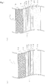
- FIG. 1 shows a road structure according to one embodiment of the present invention.
- the road structure 1 shown in FIG. 1 is formed such that an asphalt layer 18 is laminated over a base layer 10 which typically may be a concrete slab.
- a first bonding layer 12 is laminated, a corrosion-resistant conductive sheet 14 is laminated on the first bonding layer 12, a second bonding layer 16 is laminated on the corrosion-resistant conductive sheet 14, and the asphalt layer 18 is laminated on the second bonding layer 16.
- the first bonding layer 12 bonds the base layer 10 and the anti-corrosive conductive sheet 14, and the second bonding layer 16 bonds the corrosion-resistant conductive sheet 14 and the asphalt layer 18.
- This road structure 1 can be used such as for a common asphalt paved road, a concrete bridge, a culvert, a concrete structure for making a roof of a concrete building watertight.
- the base layer 10 of the road structure 1 may be a cast-in-place concrete slab or precast concrete slab.
- a typical asphalt material can be used for the asphalt layer 18 of the road structure 1, but the material needs to be non-conductive, and what does not block a magnetic field.
- a thickness of the asphalt layer 18 is 2 to 3 cm or more and about 20 cm or less, preferably 8 cm or less.
- the corrosion-resistant conductive sheet 14 is configured by a material which generates heat by an eddy current induced by electromagnetic conduction from outside and which state (for example, form, performance) does not change even buried between the asphalt layer 18 and the base layer 10 over a long period of time after being laid, and it may be, for example, a layer made entirely of a metal, a layer containing a metal for at least a part, a fiber layer, or a resin layer.
- Heat induced in the corrosion-resistant conductive sheet 14 can soften the first bonding layer 12, or the first bonding layer 12 and the second bonding layer 16.
- the corrosion-resistant conductive sheet 14 can be heated by means of electromagnetic induction even a long period of time has passed after the road structure 1 is laid, and the asphalt layer 18 can be peeled off without scratching the base layer 10 or making large noise and vibration. Further, as a rule, since the corrosion-resistant conductive sheet 14 is discarded after the asphalt layer 18 is peeled off, a less expensive material is more preferred for configuration.
- the corrosion-resistant conductive sheet 14 is of a thickness which allows for carrying a current necessary for generating heat at a degree which can soften the first bonding layer 12 or the second bonding layer 16 by electromagnetic conduction.
- the thickness has a strength such that the corrosion-resistant conductive sheet 14 does not break by a general external force acted thereon when the asphalt layer 18 is constructed on the corrosion-resistant conductive sheet 14. Since a thickness is proportional to weight, the thickness of the corrosion-resistant conductive sheet 14 can be arbitrarily selected from a viewpoint of a thickness and weight which do not interfere with conveyance and construction such as laying.
- the corrosion-resistant conductive sheet 14 is made by coating each side of a conductor layer 142 with corrosion-resistant films 144 and 146 respectively, or forming a material itself, by which the layer 14 is configured, by a corrosion-resistant material.
- the corrosion-resistant conductive sheet 14 may be any one of, for example, a metal layer having a corrosion-resistant film, a corrosion-resistant metal layer, a fiber layer having a corrosion-resistant film, a corrosion-resistant fiber layer, a resin layer having a corrosion-resistant film, a corrosion-resistant resin layer, a layer which has given a corrosion-resistant film to a mixture of a resin and a conductor, or a layer in which a corrosion-resistant resin is mixed with a conductor.
- the corrosion-resistant conductive sheet 14 for example, a sheet in which a flat sheet of conductor layer 142, a perforated sheet of conductor layer 142, or a net-like conductor layer 142 is coated with the corrosion-resistant films 144 and 146, or a sheet in which a corrosion-resistant conductive material is formed to, for example, a flat sheet, a perforated sheet, or a net, can be used.
- FIG. 1 illustrates the corrosion-resistant conductive sheet 14 in which the corrosion-resistant films 144 and 146 are respectively laminated on each side of the flat sheet of conductor layer 142.
- the conductor layer 142 may have perforated cut lines. Using such perforated corrosion-resistant conductive sheet 14 and/or corrosion-resistant conductive sheet 14 with perforated cut lines may allow an easier peeling off process where the corrosion-resistant conductive sheet 14 is cut at such hole positions when a laminate including the corrosion-resistant conductive sheet 14 is peeled off from the base layer 10, as described in the following.
- the corrosion-resistant conductive sheet 14 is a layer made entirely of a metal, or a layer containing a metal for at least a part, aluminum, stainless, iron, zinc, copper, and titanium, and an alloy composed mostly of these metals can be used as the metal.
- the metal used for the corrosion-resistant conductive sheet 14 more preferably includes an aluminum alloy, further preferably an aluminum alloy foil, and much more preferably an aluminum alloy foil which has a corrosion-resistant film on each side.
- electrical specific resistance of the aluminium alloy foil (room temperature 15 °C) is preferably 6.0 ⁇ cm or more, more preferably 6 to 10 ⁇ cm, and much more preferably 6.5 to 10 ⁇ cm.
- the upper limit of the electrical specific resistance is typically about 10 ⁇ cm, but not specifically limited thereto.
- the electrical specific resistance exceeds 10 ⁇ cm, a corrosion resistance may significantly be lowered, or processing may become difficult.
- the electrical specific resistance (room temperature 15 °C) is preferably 50 to 90 ⁇ cm, and more preferably 60 to 85 ⁇ cm.
- the aluminium alloy foil can be manufactured based on a known method; for example, it can be obtained by preparing a molten metal having a predetermined composition, and then applying a cold rolling to an aluminium alloy casted to a thickness of 10 mm or less at a cooling rate of 100 °C/second or more. As another method, it may be obtained by preparing a molten metal having a predetermined composition, and after homogenizing an ingot of an aluminum alloy obtained by casting thereof at 450 to 660 °C, preferably at 450 to 550 °C, applying a hot rolling or cold rolling thereto.
- annealing may be performed at 150 to 450 °C.
- the obtained aluminum alloy foil may be subjected to a final annealing at 200 to 600 °C according to necessity.
- Annealing time can be appropriately set, but a time to hold the temperature at 300 °C or more is preferably within 10 minutes. More preferable time to hold the temperature at 300 °C or more is within 1 minute.
- the aluminum alloy foil 142 is desirably as light as possible from a construction requirement, and as for stiffness, since high deformation performance is necessary because of a need for the following capability to the base layer underneath, the thickness is preferably 50 to 200 ⁇ m, but not limited thereto. The thickness of 50 ⁇ m or less may lead to decrease in strength as the corrosion-resistant conductive sheet 14, and when it exceeds 200 ⁇ m, construction and/or processing may become difficult.
- an average grain size of the aluminum alloy foil 142 is preferably 1 to 30 ⁇ m, more preferably 5 to 20 ⁇ m, and much more preferably 5 to 10 ⁇ m, but not limited thereto.
- the average grain size exceeding 30 ⁇ m may lead to difficulty in processing. Smaller average grain size is preferred, but is typically about 1 ⁇ m.
- Such aluminum alloy foil 142 can be obtained by using an aluminum alloy casted to a thickness of 10 mm or less at a cooling rate of 100 °C/second or more.
- the grain size in the present invention refers the maximum width of a crystal grain in a vertical direction with respect to a cold-rolling direction.
- the aluminium alloy which is a material of the aluminium alloy foil 142 desirably contains Mn of 0.5 ⁇ Mn ⁇ 3.0 percent by mass, Cr of 0.0001 ⁇ Cr ⁇ 0.20 percent by mass, Mg of 0.2 ⁇ Mn ⁇ 1.8 percent by mass, Ti of 0.0001 ⁇ Ti ⁇ 0.6 percent by mass, Cu of 0 ⁇ Cu ⁇ 0.005 percent by mass, Si of 0 ⁇ Si ⁇ 0.1 percent by mass, and Fe of 0 ⁇ Fe ⁇ 0.2 percent by mass.
- the rest of the aluminum alloy excluding these alloy elements preferably consists of A1 (aluminum) and unavoidable impurities. Further, the content of each of the unavoidable impurities is desirably 100 mass ppm or less.
- Mn contained by 0.5 ⁇ Mn ⁇ 3.0 percent by mass in the aluminum alloy has a large contribution ratio for electrical specific resistance, and it is an element which does not lose corrosion resistance. In addition, coexistence with Cr further increases the electrical specific resistance.
- the content of Mn is preferably 1.0 ⁇ Mn ⁇ 2.5 percent by mass, more preferably 1.6 ⁇ Mn ⁇ 2.2 percent by mass, and much more preferably 1.8 ⁇ Mn ⁇ 2.2 percent by mass.
- Cr contained by 0.0001 ⁇ Cr ⁇ 0.20 percent by mass in the aluminum alloy has a large contribution to electrical specific resistance, and it is an element which does not lose corrosion resistance. In addition, coexistence with Mn further increases the electrical specific resistance.
- the content of Cr is less than 0.0001 percent by mass, a necessary electrical specific resistance may not be obtained, and when the content is 0.20 percent by mass or more, a hard and coarse A1 - Cr -Mn based intermetallic compound may crystallize out, and thus, leading to defects such as pinholes.
- the content of Cr is more preferably 0.0001 ⁇ Cr ⁇ 0.18 percent by mass.
- Mg contained by 0.2 ⁇ Mg ⁇ 1.8 percent by mass in the aluminum alloy especially improves mechanical strength, and it is an element which also has a large contribution to electrical specific resistance.
- the content of Mg is less than 0.2 percent by mass, a strength necessary for construction may not be obtained, and when the content exceeds 1.8 percent by mass, the strength may become too large, leading to difficulty in the processing
- Ti contained by 0.0001 ⁇ Ti ⁇ 0.6 percent by mass in the aluminum alloy has a large contribution ratio for electrical specific resistance, and it is an element which does not lose corrosion resistance, and improves its formability by refining crystal grains of the aluminum alloy.
- the content of Ti is less than 0.0001 percent by mass, a necessary electrical specific resistance may not be obtained, and also, the average grain size of the aluminum alloy foil may become large, leading to difficulty in processing.
- the content exceeds 0.6 percent by mass the strength may become too large, leading to difficulty in the processing.
- the content of Ti is preferably 0.002 ⁇ Ti ⁇ 0.25 percent by mass.
- Cu contained by 0 ⁇ Cu ⁇ 0.005 percent by mass in the aluminum alloy is an element which lowers the corrosion resistance.
- the content of Cu exceeds 0.005 percent by mass, corroded pores may be formed in the aluminum alloy foil.
- the lower limit of the Cu content is typically about 0.0005 percent by mass but not specifically limited thereto.
- the content of Cu is more preferably 0 ⁇ Cu ⁇ 0.003 percent by mass.
- Si contained by 0 ⁇ Si ⁇ 0.1 percent by mass in the aluminum alloy is an element which lowers the electrical specific resistance to facilitate deposition of other elements. In addition, it is an element which lowers corrosion resistance especially to a weak acid. When the content of Si exceeds 0.1 percent by mass, corroded pores may be formed in the aluminum alloy foil.
- the lower limit of the Si content is typically about 0.0005 percent by mass but not specifically limited thereto.
- the content of Si is more preferably 0 ⁇ Cu ⁇ 0.04 percent by mass.
- Fe contained by 0 ⁇ Fe ⁇ 0.2 percent by mass in the aluminum alloy is an element which specifically improves mechanical strength but lowers corrosion resistance. When the content of Fe exceeds 0.2 percent by mass, corroded pores may be formed in the aluminum alloy foil.
- the lower limit of the Fe content is typically about 0.0005 percent by mass but not specifically limited thereto.
- the content of is more preferably 0 ⁇ Fe ⁇ 0.08 percent by mass.
- A1 which is a main component of the aluminum alloy is excellent in heat conductivity, light, inexpensive, and easy to be processed.
- elements such as Fe, Si, Cu, Ti, V, Ga get mixed in as impurity elements typically in a process of smelting, purifying, and ingotting of aluminum, but the content of such elements can be adjusted by combining and blending various qualities (grades) of aluminum.
- the aluminum alloy used for the corrosion-resistant conductive sheet 14 according to the present invention is manufactured by adding and blending a certain kind of element as a significant element after the impurity elements are adjusted.
- the aluminum alloy foil 142 consisting of this aluminum alloy can contain each of the above-described elements in a range where the electrical specific resistance (room temperature 15 °C) is 6.0 ⁇ cm or more, preferably 6.0 to 10 ⁇ cm, more preferably 6.5 to 10 ⁇ cm.
- the electrical specific resistance is less than 6.0 ⁇ cm, the thickness of the corrosion-resistant conductive sheet must be made thinner to obtain a necessary resistivity, leading to decrease in strength of the corrosion-resistant conductive sheet 14.
- the upper limit of the electrical specific resistance is typically about 10 ⁇ cm, but not specifically limited thereto. It is because when the electrical specific resistance exceeds 10 ⁇ cm, corrosion resistance may significantly be lowered, or processing may become difficult.
- the material of the corrosion-resistant films 144 and 146 used for the corrosion-resistant conductive sheet 14 may be any material as long as the conductor layer 142 can be protected from corrosion, but not specifically limited thereto.
- As the corrosion-resistant films 144 and 146 for example, a glass-based film, a fluorinated film, an acrylic film, a styrene film, polycarbonate film, a polyester film, a polyurethane film, epoxy film, a Teflon (Registered Trademark) film, a tin plating, zinc plating, a zinc alloy clad, an oxide film, phosphate treatment film, a phosphoric salt treatment film, a chromic acid treatment film, a chromate salt treatment film, a hydrofluoric acid treatment film, a hydrofluoric acid salt treatment film, a sodium salt treatment film, or any one selected from a group consisting of niobium, titanium, tantalum, silicon and zirconium metal passive oxide film formed by a ca
- the corrosion-resistant films 144, 146 are more preferably a glass-based film or an epoxy film. Each of the films 144 and 146 preferably has good bonding characteristic with the first bonding layer 12 and the second bonding layer 16, and has high slipping-resistance characteristic, tensile strength-resistance characteristic, stripping-resistance characteristic etc.
- the first bonding layer 12 is located between the base layer 10 and the corrosion-resistant conductive sheet 14, as shown in FIG. 1 , and it is a thermoplastic material which may rigidly bond the base layer 10 and the corrosion-resistant conductive sheet 14 when the corrosion-resistant conductive sheet 14 is laid, and be softened by heat induced in the corrosion-resistant conductive sheet 14 when the asphalt layer 18 is peeled off.
- the first bonding layer 12 may be softened by the heat of the corrosion-resistant conductive sheet 14 which generates heat by means of electromagnetic conduction, lowering a bonding force between the base layer 10 and the corrosion-resistant conductive sheet 14 to allow for separating layers located on and under the first bonding layer 12.
- the first bonding layer 12 preferably has a softening point T1 determined by a softening point test method generally used in an asphalt characteristic test of about 50 °C to about 80 °C, and it is more preferable to be 10 to 15 °C or more lower than a softening point T2 of the second bonding layer 16 described in the following.
- the softening point is an index showing a temperature when a solid substance of a thermoplastic material such as asphalt plastically deforms continuously by an increase in temperature, and softens to a predetermined degree.
- the softening point of asphalt is a temperature where asphalt is dipped as low as a defined distance when a steel ball is put on asphalt which has been poured into a ring-shaped form in a melted liquid state and then cooled and solidified, and the temperature is elevated with a certain temperature gradient.
- a material having a lower softening point than the second bonding layer 16 is used as a material of the first bonding layer 12, and a temperature at which the corrosion-resistant conductive sheet 14 generates heat by means of electromagnetic induction is controlled to a temperature with which the first bonding layer 12 softens but the second bonding layer 16 does not, the layers located on and under the first bonding layer 12 are easily separated.
- a relationship between a difference of the softening points of the first bonding layer 12 and the second bonding layer 16, and a position to separate the road structure 1 into two layers may be considered as in the following.
- a relationship between temperature (Tem) and a degree of viscosity ( ⁇ ) of the materials used for the first bonding layer 12 and the second bonding layer 16 is represented as a curve approximated to a negatively sloped nearly straight line on a temperature (Tem) - viscosity ( ⁇ ) characteristic diagram of the materials used for the bonding layers.
- This temperature-viscosity characteristic diagram is commonly represented as “log (log ⁇ )-log (Tem)" diagram in which a logarithm of temperature (log (Tem ⁇ )) is made as the horizontal axis, and a log-log of viscosity (log (log ⁇ )) is made as the vertical axis.
- this temperature - viscosity characteristic diagram is sometimes represented as a characteristic diagram in which temperature (Tem) is made as the horizontal axis, and a logarithm of viscosity (log ⁇ ) is made as the vertical axis, that is, a "log ⁇ - Tem" diagram.
- a straight line representing the second bonding layer 16 may be plotted above a straight line representing the first bonding layer 12 which softening point is lower, with a certain distance.
- the vertical axis is represented as the log-log as described in the above, thus, even if the difference between the softening point of the first bonding layer 12 and the softening point of the second bonding layer 16 is 10 °C to 15 °C, a difference of viscosity which corresponds to the difference of softening points is large. Therefore, by making the first bonding layer 12 and the second bonding layer 16 with materials which difference of the respective softening points is 10 to 15 °C or more, when the corrosion-resistant conductive sheet 14, which makes up the road structure 1, is heated by generating induction current inducing current by means of electromagnetic conduction, the layers located on and under the first bonding layer 12, which has lower viscosity, are more easily separated, not the second bonding layer 16.
- the first bonding layer 12 is desirably made of a material which state (corrosion resistance, bonding between the base layer 10 and the corrosion-resistant conductive sheet 12 etc.) does not change even if a situation continues where it is buried between the asphalt layer 18 and the base layer 10 for a long period of time.
- the material which may be used as the first bonding layer 12 may be, for example, any one selected from a group consisting of, synthetic rubber, acrylic resin, epoxy resin, acrylic acid, methacrylic acid, acrylic radical curable liquid resin, polyurethane resin, ethylene-vinyl acetate copolymer, urethane resin, and bituminous material, or mixture of these substances, but not limited thereto.
- a thickness of the first bonding layer 12 may be any thickness as long as the base layer 10 and the corrosion-resistant conductive sheet 14 are securely bonded.
- the thickness may be determined such that the unevenness is absorbed during laying of the corrosion-resistant conductive sheet 14 to securely attach the corrosion-resistant conductive sheet 14 and the base layer 10.
- the thickness is preferably as thin as possible from a viewpoint of workability and economic efficiency.
- the second bonding layer 16 is located between the corrosion-resistant conductive sheet 14 and the asphalt layer 18, as shown in FIG. 1 , and it is a thermoplastic material which may rigidly bond the corrosion-resistant conductive sheet 14 and the asphalt layer 18 when the asphalt layer 18 is laid, and be softened by heat induced in the corrosion-resistant conductive sheet 14 when the asphalt layer 18 peeled off.
- the second bonding layer 16 may be softened by the heat of the corrosion-resistant conductive sheet 14 which generates heat by means of electromagnetic conduction when the asphalt layer 18 is peeled off, lowering a bonding force between the corrosion-resistant conductive sheet 14 and the asphalt layer 18 to allow for separating layers located on and under the second bonding layer 16.
- the second bonding layer 16 preferably has a softening point T2 of about 60 °C to about 90 °C, and it is more preferable to be 10 °C to 15 °C or more higher than the softening point T1 of the first bonding layer 12 as described in the description of the first bonding layer 12.
- T2 softening point
- T1 softening point
- the second bonding layer 16 is desirably made of a material which state (corrosion resistance, bonding between the corrosion-resistant conductive sheet 14 and the asphalt layer 18 etc.) does not change even if a situation continues where it is buried between the asphalt layer 18 and the base layer 10 for a long period of time.
- a thickness of the second bonding layer 16 may be any thickness as long as the corrosion-resistant conductive sheet 14 and the asphalt layer 18 are securely bonded, but the thickness is preferably as thin as possible from a viewpoint of workability and economic efficiency.
- the material which may be used as the second bonding layer 16 may be any one selected from a group consisting of, for example, ethylene-vinyl acetate copolymer, polyolefin resin, polyamide resin, polyester resin, polyurethane resin, polystyrene resin, polypropylene resin, polyvinyl acetate resin, polyethylene resin, polyethylene terephthalate resin, polyamide-imide resin, styrene-butadiene block copolymer (SBS) resin, chloroprene (CR) resin, styrene-isoprene block copolymer (SIS) resin, polybutadiene resin, and bituminous material, or mixture of these substances, but not limited thereto.
- SBS styrene-butadiene block copolymer
- CR chloroprene
- SIS styrene-isoprene block copolymer
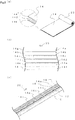
- the corrosion-resistant conductive sheet 14 shown in FIG. 1 can be carried into a construction site in a form, for example, of a corrosion-resistant conductive sheet 14 preliminarily processed to a band-like sheet.
- FIG. 2 (a) shows a roll 22 of corrosion-resistant conductive sheet 14 as an example.
- Such corrosion-resistant conductive sheet 14 may allow for laying the road structure 1 easily by laying the first bonding layer 12 on the base layer 10, taking the corrosion-resistant conductive sheet 14 out from the roll 22, for example, for laying thereon, bonding the base layer 10 and the corrosion-resistant conductive sheet 14 through the first bonding layer 12, laying the second bonding layer 16 on the corrosion-resistant conductive sheet 14, laying the asphalt layer 18 thereon, and bonding the corrosion-resistant conductive sheet 14 and the asphalt layer 18 through the second bonding layer 16.
- the corrosion-resistant conductive sheet 14 is exampled in FIG. 2 (a) as a form in which the band-like sheet is rolled into the roll 22, but not limited thereto.
- a plurality of rectangular corrosion-resistant conductive sheets 14 may be prepared to be laid out on the second bonding layer 12.
- FIG. 1 (b) shows a road structure according to the second embodiment of the present invention.
- the road structure 1a shown in FIG. 1 (b) is different from the first embodiment of the present invention in that a watertight layer 26 is located between the base layer 10 and the first bonding layer 12.
- the watertight layer 26 is located between the base layer 10 and the first bonding layer 12 as shown in FIG. 1 (b) , and functions to prevent water entered in the road structure 1a from reaching the base layer 10.
- the watertight layer 26 is preferably made of a material which watertight performance does not change even if it is buried between the asphalt layer 18 and the base layer 10 over a long period of time.
- the material for the watertight layer 26 preferably has a high bonding characteristic with the base layer 10 and the first bonding layer 12.
- a coated watertight layer, a watertight sheet, a mortar + watertight sheet layer etc. may be used as the watertight layer 26, a coated watertight layer, a watertight sheet, a mortar + watertight sheet layer etc. may be used.
- the coated watertight layer for example, a synthetic rubber watertight layer, a combination of a high ductility FRC material and a resin material, a combination of an acrylic resin and an asphalt-based bonding layer, a combination of an epoxy resin and an asphalt-based bonding layer, a composite polymer resin of acrylic acid and methacrylic acid, a combination of an acrylic radical curable liquid resin and an asphalt watertight agent, a combination of a polyurethane resin, urethane adhesive, and an ethylene vinyl acetate, or a combination of an urethane watertight layer and urethane reactive hotmelt adhesive etc.
- a synthetic rubber watertight layer a combination of a high ductility FRC material and a resin material
- a combination of an acrylic resin and an asphalt-based bonding layer a combination of an epoxy resin and an asphalt-based bonding layer
- a composite polymer resin of acrylic acid and methacrylic acid a combination of an acrylic radical curable liquid resin and an asphalt watertight agent,
- watertight sheet for example, a pour and bond type sheet, a heat and contact sheet, an ambient temperature non-pressuring bonding sheet, an ambient temperature pressuring bonding sheet, a watertight layer made by sandwiching a fiber sheet between asphalt etc. may be used, but not limited thereto.
- the mortar + watertight sheet layer for example, a watertight layer made by mending the base layer with a cement-based mortal and emulsion and then applying an asphalt-based watertight sheet, a watertight layer in which a reinforcement layer having a fiber sheet sandwiched between resin mortals, and a watertight sheet, and an asphalt rubber adhesive are combined, a watertight layer in which a non-woven fabric is sandwiched between stretching materials consisting of a hydraulic cement and a synthetic resin emulsion may be used, but not limited thereto.
- a peeling apparatus for peeling the asphalt layer 18 in the road structure 1, 1a has components of, basically, an electromagnetic induction coil which may heat the corrosion-resistant conductive sheet 14 included in the road structure 1, 1a by means of electromagnetic conduction, a high-frequency power generating unit and a power source which may supply a high-frequency power to the electromagnetic induction coil, and a peeling member which wedge-shaped tip is inserted into the heated and softened bonding layer to allow for separating the base layer 10 and the asphalt layer 18.
- the peeling apparatus is preferably a low-noise and low-vibration apparatus, and more preferably, a noise-free and vibration-free apparatus.
- the peeling apparatus is preferably an apparatus which can heat the conductive sheet so that the bonding layer is softened to a degree necessary to peel off the asphalt layer, and which is a self-propelled apparatus enabling the electromagnetic conductive coil to move at a certain speed, for example, an apparatus of a type which a self-propelled vehicle tows the electromagnetic induction coil, and more preferably which includes a magnetic flux shielding mechanism to prevent a magnetic flux from the electromagnetic induction coil from leaking outside.
- the peeling apparatus preferably includes a mechanism for moving the electromagnetic induction coil, which allows the coil position to be controlled freely so that the electromagnetic induction coil can be located at an arbitrary position on the upper surface of the asphalt layer depending on a road surface condition.
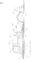
- FIG. 3 shows an apparatus for peeling off the asphalt layer 18 in the road structure 1 or 1a according to an embodiment of the present invention.
- This apparatus is an example of a basic configuration, and not limited to hereto.
- the first bonding layer 12, the corrosion-resistant conductive sheet 14, the second bonding layer 16 and the asphalt layer 18 are laminated in this order.
- a truck for loading and towing apparatus 50 is on the asphalt layer 18.
- a forward moving direction 20 of the truck for loading and towing apparatus 50 is a direction which the asphalt layer 18 is peeled (hereinafter "peeling direction").
- peeling direction a direction which the asphalt layer 18 is peeled.
- each of the thickness of the first bonding layer 12, the corrosion-resistant conductive sheet 14, and the second bonding layer 16 is shown thicker than reality.
- an apparatus and method for peeling off the asphalt layer 18 in the road structure 1 are described, but the same apparatus can be used also in the road structure 1a.
- an electromagnetic induction coil unit 32 is on the upper surface of the asphalt layer 18 at a position on a trailing side relative to the truck for loading and towing apparatus 50.
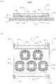
- FIG. 4 shows an example of a coil unit suitable in using for a peeling method according to the present invention.
- the coil unit 32 is arranged as that, as shown in a plan view of FIG. 4 (b) , when a direction shown by an arrow 20 is a traveling direction (peeling direction), three electromagnetic induction coils 46 are arranged with even intervals in a lateral direction which passes transversely across the traveling direction at the rear inside of a frame member 44 made of FRP, for example.
- two electromagnet induction coils 46 are arranged in the lateral direction, with a distance approximately half of a coil being displaced with respect to the arrangement of the rear electromagnetic induction coils 46.
- Such arrangement of the electromagnetic induction coils with respect to the traveling direction enables uniform application of current based on electromagnetic induction to the corrosion-resistant conductive sheet 14, and thus, more uniform heating of the corrosion-resistant conductive sheet 14 is possible.
- the arrangement of the electromagnetic induction coils 46 in the coil unit 32 is not limited to the arrangement shown in FIG. 4 , and it is preferable to design thereof depending on a condition of the road structure 1 including the asphalt layer 18 and/or a form of the corrosion-resistant conductive sheet 14.
- FIG. 4 (a) as shown in FIG. 4 (a) which is a cross-sectional view passing transversely across a center part of the two electromagnetic induction coils 46 arranged at the front relative to the traveling direction 20 in FIG. 4 (b) , the electromagnetic induction coils 46 are secured to the frame member 44, and on each of the upper surfaces of the electromagnetic induction coils 46, ferrite members 48 are arranged radially with respect to a center of the electromagnetic induction coils 46.
- the frame member 44 has a board 47 formed to have a thickness approximately equal to that of the ferrite member 48 and provided at a vertically intermediate layer thereof to extend approximately in a horizontal direction.
- a top plate 44B of the frame member 44 is preferably a detachable cover.
- the top plate 44B can be detached to facilitate a maintenance operation for the electromagnetic induction coils 46.
- Four wheels 49 are provided in respective four corners of the frame member 44.
- the coil unit 42 is adapted to allow a plurality of the coil units 42 to be connected to each other in the lateral direction.
- a lower surface of each of the electromagnetic induction coils 46 is preferably disposed in adjacent relation to the upper surface of the asphalt layer 18 as close as possible to reduce a distance between the upper surface of the corrosion-resistant conductive sheet 14 and the lower surface of the electromagnetic induction coils 46.
- a high-frequency power generating unit 56 for supplying a high-frequency power to the electromagnetic induction coils 46 via an electric cable 58, and a power generator 57 serving as a power source of the high-frequency power generating unit 56, are mounted on a loading platform of the truck for loading and towing apparatus 50.
- a supporting column 59 is fixed to a rear end of the truck for loading and towing apparatus 50 to protrude downwardly, and the supporting column 59 is coupled to the coil unit 32 through a fixture or pulling wire 56 integrated with the truck for loading and towing apparatus 50, or integrally connected thereto.
- a small turning-type backhoe 74 with a ripper 70 serving as a peeling member attached to a distal end of an arm 72 is driven onto the base layer 10 at a position on a trailing side relative to the coil unit 42.
- a part of the base layer 10 where the backhoe 74 and the ripper 70 are placed is preferably exposed in advance as a part to allow for the ripper 70 to start the peeling operation.
- a plurality of cut lines substantially parallel to the travelling direction 20 are preferably formed in the asphalt pavement 18 of the road structure 1 such as by a cutting blade (not shown) before starting the peeling process, from a viewpoint of easy operation.
- the asphalt pavement 18 may be segmented into three lanes extending in the traveling direction 20.
- a plurality of cut lines may be formed in the asphalt pavement 18 of the road structure 1 such as by the cutting blade in a direction passing transversely across the traveling direction 20. Such cut lines facilitate the asphalt layer 18 to be peeled off and removed from above the base layer 10.
- the coil unit 42 is placed at a position to be peeled off (hereinafter "peeling position") which is, for example, the extreme of the three lanes, on the asphalt pavement 18. Further, when the asphalt pavement 18 is segmented into a plurality of lanes, each of the coil units 42 may be placed on the corresponding lanes to peel off the respective asphalt layers 18 simultaneously from all of the lanes.
- peeling position a position to be peeled off
- the coil unit 42 is placed at a position to be peeled off (hereinafter "peeling position") which is, for example, the extreme of the three lanes, on the asphalt pavement 18.
- each of the coil units 42 may be placed on the corresponding lanes to peel off the respective asphalt layers 18 simultaneously from all of the lanes.
- a high-frequency power is supplied from the high-frequency power generating unit 56 to the electromagnetic induction coils 46 of the coil units 42 via the electric cable 58
- an eddy current based on electromagnetic induction is produced in the corrosion-resistant conductive sheet 14 of
- the truck for loading and towing apparatus 50 is moved in the forward traveling direction to pull each of the coil units 42 so as to gradually move the coil units 42 in the peeling direction 20.
- a moving speed of the coil unit 42 may be appropriately set depending on a heating capability of the coil unit 42 and a desired speed of the peeling operation.
- the two electromagnetic induction coils 46 at the front are arranged in side-by-side relation to each other in the lateral direction, with a distance approximately half of a coil being displaced with respect to the arrangement of the electromagnetic induction coils 46 at the rear, and thus, the eddy current may be produced in the corrosion-resistant conductive sheet 14 entirely without any space.
- the ripper 70 may be inserted into the softened first bonding layer 12 to peel off the asphalt pavement 18 from the base layer 10.
- the tip of the ripper 70 is preferably inserted between the base layer 10 and the first bonding layer 12.
- a thickness of the tip of the ripper 70 commonly used is a few dozen mm (for example, about 30 mm). Therefore, the tip of the ripper 70 is not inserted into a certain one of the first bonding layer 12, the corrosion-resistant conductor layer 14, and the second bonding layer 16, but these layers are collectively hooked and lifted, and peeled from the layer which bonding force became the lowest during such time.
- a sheet with weakness is used as the corrosion-resistant conductive sheet 14, in which weakness to tensile break such as a plurality of holes or perforations are provided with appropriate spaces in a direction orthogonal to a peeling direction of the conductor layer 142, for example, in a case of a band-like sheet, in which a row of weakness straightly aligned in a cross direction of the sheet are provided with appropriate spaces in a length direction, when the layer including the corrosion-resistant conductive sheet 14 is peeled and lifted by the ripper 70, the peeled portion and the not-peeled portion can be fragmented at this weak part, and thus, the peeling step can be performed more easily.
- the process after the peeling of a layer 24 from the first bonding layer 12 to the asphalt layer 18 (or, a plurality of layers 24 at least including the asphalt layer 18), peeled off from the base layer 10 by the ripper 70 is not specifically limited.
- the peeled off layer 24 including the asphalt layer 18 may be cut to appropriately length with respect to the travelling direction 20, or may be cut at cut lines provided in advance, and then lifted by the ripper 70 and leave it on a side of the road structure 1 by turning the arm 72 of the backhoe 74.
- the peeled off layer 24 left aside is taken out in the later step.
- the peeling apparatus may be moved continuously in the traveling direction 20, with the peeled layer 24 including the asphalt layer 18 remaining on the base layer 10 to remove the peeled layer 24 remaining on the base layer 10 later. This process enables protecting the exposed base layer 10 by fracture pieces of the peeled layer 24.
- FIG. 1(a) The configuration of the road structure 1 is shown in FIG. 1(a) .
- the base layer 10 is laid by cast-in-place of concrete or by locating a preliminarily constructed concrete slab etc. on a laying position. Then, the first bonding layer 12 is laid on the base layer 10. The first bonding layer 12 is laid such as by blowing or coating a material heated to an appropriate melting temperature on the base layer 10. The first bonding layer 12 may double a primer coated on a surface of the base layer 10, but a primer may be separately coated on the surface of the base layer 10 before the first bonding layer 12 is laid, according to necessity.
- the road structure 1a shown in FIG. 1 (b) shows a case where the watertight layer 26 is laid on the base layer 10 before the first bonding layer 12 is laid.
- the watertight layer 26 is laid on the base layer 10 by a common construction method such as coating, blowing, pouring and bonding, heat welding, adhesion at a normal temperature depending on a material of the watertight layer 26 used.
- the first bonding layer 12 is laid thereon as described in the above.
- the corrosion-resistant conductive sheet 14 is laid on the first bonding layer 12.
- the corrosion-resistant conductive sheet 14 may be a corrosion-resistant conductive sheet preliminarily processed to a band-like sheet form as shown in FIG. 2 (a) .
- the corrosion-resistant conductive sheet 14 can be laid by setting the roll 22 above the first bonding layer 12, taking the corrosion-resistant conductive sheet 14 out from the roll 22, positioning the taken out sheet 14 on a predetermined position of the first bonding layer 12, and at the same time, cutting the sheet by an appropriate length depending on predetermined laying zones.
- the corrosion-resistant conductive sheet 14 when the corrosion-resistant conductive sheet 14 is prepared as a rectangular sheet divided into a predetermined size, for example, about 50 cm to 180 cm square size, the corrosion-resistant conductive sheet 14 can be laid by arranging a plurality of rectangular sheets 14 on the first bonding layer 12.
- the corrosion-resistant conductive sheet 14 When laying the corrosion-resistant conductive sheet 14, as shown in FIG. 2 (b) , the corrosion-resistant conductive sheet 14 is preferably laid with its ends overlapped so that no gap may exist between adjacent sheets. Alternatively, the corrosion-resistant conductive sheet 14 may be laid such that end faces of adjacent sheets surely come end-to-end with each other. When the ends are overlapped for the laying, specifically, first, the corrosion-resistant conductive sheet 14a is laid at a position shown at the upper part of FIG. 2 (b) in a laying direction shown by an arrow 20.
- the corrosion-resistant conductive sheet 14b is positioned such that the right-side end thereof in the traveling direction overlaps the left-side end of the corrosion-resistant conductive sheet 14a, and also, the tip portion thereof is located rear in the traveling direction than the tip portion of the corrosion-resistant conductive sheet 14a. Then, corrosion-resistant conductive sheets 14c to 14f are similarly laid.
- the corrosion-resistant conductive sheet 14 g is similarly laid.
- the corrosion-resistant conductive sheet 14 g is located such that the right-side end thereof in the traveling direction corresponds with the right-side end of the corrosion-resistant conductive sheet 14a, and the rear end thereof overlaps the tip of the corrosion-resistant conductive sheet 14a.
- the corrosion-resistant conductive sheet 14h is located such that the right-side end thereof overlaps the left-side end of the corrosion-resistant conductive sheet 14g, and the rear end overlaps the tip of the corrosion-resistant conductive sheet 14b.
- corrosion-resistant conductive sheets 14i to 141 are similarly laid.
- a watertight effect can be improved by laying the corrosion-resistant conductive sheets 14 such that the ends overlap with each other. In a case where the watertight layer 26 is laid, it is more efficient when the ends of the corrosion-resistant conductive sheet 14 are located such that they come end-to-end, not overlapped.
- the corrosion-resistant conductive sheets 14m to 14q are preferably laid such that an end at the upper side of the ramp of the corrosion-resistant conductive sheet 14 laid at the lower side of the ramp is slid under an end at the lower side of the ramp of the corrosion-resistant conductive sheet 14 laid at the upper side of the ramp.
- the corrosion-resistant conductive sheet 14 is laid, with the upper end of the corrosion-resistant conductive sheet 14 located at the lower side of the ramp is positioned under the lower end of the corrosion-resistant conductive sheet 14 located at the upper side of the ramp to allow for improving the watertight effect to water flowing from the upper side to the lower side of the ramp.
- the second bonding layer 16 is laid on the corrosion-resistant conductive sheet 14 laid as described in the above.
- the second bonding layer 16 is laid by, for example, blowing or coating a material heated to an appropriate melting temperature on the corrosion-resistant conductive sheet 14.
- the asphalt layer 18 is laid on the second bonding layer 16.
- the asphalt layer 18 is laid by laying and smoothing a heated and softened asphalt mixture on the second bonding layer 16 by, for example, an asphalt finisher, and rolling by a rolling machine.
- FIG. 5 shows a configuration of the test sample used in the test.
- a primer styrene-butadiene copolymer + petroleum resin + toluene
- 1.2 kg/m 2 of heated asphalt asphalt + petroleum-based hydrocarbon + petroleum resin + styrene-butadiene copolymer
- a conductor layer was laid on the upper surface of the heated asphalt, and an asphalt-based watertight sheet was laid on the upper surface thereon.
- a conductor layer four sheets; a corrosion-resistant conductive sheet (described as IH aluminum in FIG. 5 ), an aluminum sheet (described as aluminum in FIG. 5 ), an FRP sheet, and a stainless sheet were used.
- An electromagnetic coil having a diameter of 28.5 cm was used to heat the test sample from above the asphalt-based watertight sheet to check the state of the asphalt layer.
- Two conductor layers of A4 size (210 mm x 297 mm) were prepared to make a test sample by making the ends of these conductor layers overlapped with each other by 100 mm, and a heating test was conducted using an electromagnetic induction coil having a diameter of 28.6 cm.
- a conductor layer four sheets; a corrosion-resistant conductive sheet, an aluminum sheet, an FRP sheet, and a stainless sheet were used. Details of these sheets are the same as what have been used in the test in (1) above.
- a corrosion-resistance test was conducted for the corrosion-resistant conductive sheet according to the present invention to check as to whether corrosion has occurred. At the same time, measurement of electrical specific resistance and an electromagnetic induction heating characteristic test are also conducted. Table 1 shows a configuration for each test sample, and chemicals used in the corrosion resistance test for Examples 1 to 6 and Comparative Examples 1 and 2.
- a stainless foil having a thickness of 80 ⁇ m was directly used.
- each test sample (100 mm x 100 mm) was immersed in Ca (OH) 2 0.17 WL % water solution (saturated calcium hydroxide solution) (described as Chemical A in Table 1), or NaCl3 wt% water solution (3% salt solution) (described as Chemical B in Table 1), and a surface state was observed visually after 15 days.
- a o mark shows that the test sample had no change in color or corrosion
- x mark shows that the test sample was corroded, and a through-hole was made.
- the electrical specific resistance ( ⁇ cm) was measured at a room temperature (15 °C) by a direct current four-terminal method for each test sample.
- an IH characteristic test was conducted by using a commercially available IH cooking device (power of 1400W) to examine as to whether the metal foil (a thickness of 80 ⁇ m) used for each of the test samples reaches 90 °C from the room temperature within 10 seconds.
- an infrared camera was used to check as to whether heating is done uniformly.
- Table 1 shows that the temperature of the test sample reached 90 °C within 10 seconds and also the test sample was uniformly heated, and the x mark shows that the temperature of the test sample did not rise.
Landscapes
- Engineering & Computer Science (AREA)
- Architecture (AREA)
- Civil Engineering (AREA)
- Structural Engineering (AREA)
- Mining & Mineral Resources (AREA)
- Physics & Mathematics (AREA)
- Electromagnetism (AREA)
- Road Paving Structures (AREA)
- Road Repair (AREA)
Description
- The present invention relates to a road structure according to the preamble of
claim 1 and a method for peeling off an asphalt layer from a base layer in such road structure according toclaim 8. - As a method for peeling off an asphalt layer paved on a base of a concrete slab which is a bad conductor of electricity during a repair work of an asphalt-paved road or the like, a method of peeling off the asphalt layer from the concrete slab by a cutting machine is commonly used. However, when such method is used, a concrete slab which is not intended to be cut is cut by the cutting machine, and the concrete slab becomes thinner each time the asphalt layer is a peeled off during the repair work. In addition, microcracks may be made on the cut concrete slab due to impact thereon by the cutting machine, which deteriorates the concrete slab by corrosion, salt damage, freeze or the like of reinforcing steels in the concrete slab because of water entry, such as rain water, into the microcracks. Moreover, since problems of large vibration and/or noise are generated during the work, and the operation efficiency is extremely low, the application is limited to small-scale repair works.
- With respect to a technique of peeling an asphalt layer paved on a steel plate deck of a bridge or the like, a removing method and apparatus as disclosed in
Patent Literature 1 are proposed. In the technique disclosed inPatent Literature 1, the steel deck plate is subjected to electromagnetic induction heating to soften a part of the asphalt layer, and the softened layer is peeled off from the steel deck plate to peel of the asphalt layer. According to this technique, the asphalt layer can be peeled off from the steel deck plate without scratching the steel deck plate or making large vibration and/or noise. For the asphalt layer paved on the concrete slab, as withPatent Literature 1, there is also a need for a method for peeling off the asphalt layer without scratching the concrete slab or making noise and vibration. -
Patent Literature 2 proposes a construction method of block pavement using heat based on electromagnetic induction. In this technique, a thermoplastic material and metal material are blended or laid in a bed mortal or on its surface which is to be laid on a base layer, and after paving blocks are laid and arranged on the bed mortal, electromagnetic induction is given from above the paving block so that the metal material is heated to soften the thermoplastic material, and the paving blocks are securely crimped to the bed mortal and located at predetermined positions. The softened thermoplastic material hardens during a process of returning to room temperature, and thus, the bed mortal and the paving blocks are integrated. - The technique of
Patent Literature 2 is absolutely a technique for use in laying the paving blocks, and use of electromagnetic induction heating is not at all contemplated in removing the paving blocks. Thus,Patent Literature 2 does not refer to corrosion resistance to corrosion with age of the metal material blended in the bed mortal or laid on its surface. When any corrosion-resistance treatment is not applied to the metal material, it is expected that damages and defects due to corrosion are certainly caused in the metal material resulting from not being able to avoid percolation of rain water etc. after a long period has passed from the laying. Then, an attempt to subject the metal material to electromagnetic induction heating may not allow the metal material to be appropriately heated because of the corrosion and defects, and as a result, the bed mortal cannot be softened, and thus, the paving blocks cannot be peeled off without scratching the base layer or making large noise and/or vibration in the peeling operation. It is difficult to avoid corrosion with age due to a flood of seawater in roads passing near the seashore, and moreover, percolation water by acid rain etc. - In addition, in the technique described in
Patent Literature 2, the bed mortal is softened by the heat of the metal material based on electromagnetic induction, and pressure is applied onto the paving blocks, with the state of the bed mortal kept, to bond the bed mortal and the paving blocks. During such process, application of pressure onto the paving blocks, with the bed mortal being softened, enables the bed mortal under the paving blocks to flow laterally to result in filling gaps of joints between the paving blocks up to necessary positions. Thus, the base mortar needs to be laid with a thickness sufficient to correspond to an amount necessary for filling the joints between the paving blocks. When the paving blocks laid as such are loaded over a long period of time, each of the paving blocks separately sinks, accompanied by the lateral flow of the bed mortal under the paving blocks, resulting in further increase in the amount of the paving blocks sinking downward. The bed mortal has smaller deformation resistance compared with that of the paving blocks, and thus, when the metal material is of a sheet or a net, a shear break may be caused in the metal material due to a punching shear force by the paving blocks which have sunk downward. When the metal material in the bed mortal breaks, induction current based on electromagnetic induction may not be generated in the metal material, or it may be generated just locally, and in such case, the base mortar does not soften or does not soften sufficiently, and thus, removal of the paving blocks may become impossible or very difficult. -
Patent Literature 3 discloses an adhesive sheet which is easily peeled from an adherend, and a method for peeling off the adhesive sheet. In this technique, the adhesive sheet is configured by a thermal adhesive layer using natural or petroleum asphalt, a heat generating layer laminated thereon, and a substrate layer laminated further thereon. When peeling off the adhesive sheet, the heat generating layer is made to induce heat based on electromagnetic induction, and the thermal adhesive layer is melted or softened by such heat to allow the adhesive sheet to be peeled off from a paved road.Patent Literature 3 is a technique related to the adhesive sheet which can be used, for example, as a sign and/or marking etc. of a paved road, and a method for peeling off the sheet itself, and its technical field and structural concept is completely different from the invention according to the present application where an asphalt layer formed on a conductor layer is intended to be peeled off via a thermal bonding layer after a long period has passed. Therefore,Patent Literature 3 does not disclose or suggest any technical means from a viewpoint of corrosion resistance. -
- Patent Literature 1: Japanese Patent Number
4330639 - Patent Literature 2: Laid-Open Japanese Patent Application Publication:
JP2013-142252A - Patent Literature 3: Laid-Open Japanese Patent Application Publication:
JP H07-179828A -
EP-A-2003248 describes a method to allow an asphalt pavement to be peeled off efficiently with a relatively small amount of electric power without generating large vibration and noise, and handled in the form of a block. An electromagnetic induction coil is positioned above an asphalt pavement provided on a copper plate to melt a lower surface of the asphalt pavement. Then, a wedge-shaped thermally-conductive peeling member having a peeling layer formed on an upper surface thereof is inserted into a melted layer of the lower surface of the asphalt pavement to peel off the asphalt pavement from the steel plate. This makes it possible to peel off the asphalt pavement with a relatively small amount of electric power and handle the peeled asphalt pavement in the form of a block. - It is an object of the present invention to provide a technique, in an asphalt-paved road where an asphalt layer is laid typically on a concrete base layer, to allow for easily separating the base layer and the asphalt layer without scratching the base layer and making large noise and vibration, even a long period of time has passed after the asphalt layer is laid.
- The above problem is solved by first laying a corrosion-resistant conductive sheet between the base layer and the asphalt layer via bonding layers, subjecting the anti-corrosive conductive sheet to electromagnetic induction heating when peeling off the asphalt layer to soften the bonding layer, and separating the layer located on the softened bonding layer and the layer located under the softened bonding layer.
- In order to achieve the above problem, the present invention provides, in one aspect, a road structure configured such that an asphalt layer is peeled off by electromagnetic induction heating. The road structure comprises a non-thermoplastic base layer which is a bad conductor of electricity, and an asphalt layer located above the base layer. Between the base layer and the asphalt layer, the road structure has a corrosion-resistant conductive sheet which generates heat based on electromagnetic induction, a first bonding layer which functions to bond the corrosion-resistant conductive sheet and the base layer, and a second bonding layer which functions to bond the corrosion-resistant conductive sheet and the asphalt layer. At least the first bonding layer is a thermoplastic bonding layer which softens by heat generated by the corrosion-resistant conductive sheet. The corrosion-resistant conductive sheet is preferably any one of a metal layer having a corrosion-resistant film, a corrosion-resistant metal layer, a fiber layer having a corrosion-resistant film, a corrosion-resistant fiber layer, a resin layer having a corrosion-resistant film, a corrosion-resistant resin layer, a layer which has given a corrosion-resistant film to a mixture of a resin and a conductor, or a layer in which a corrosion-resistant resin is mixed with a conductor.
- In a comparative example, we provide a corrosion-resistant conductive sheet used for a road structure configured such that an asphalt layer is peeled off by electromagnetic induction heating, and located between a base layer and an asphalt layer of the road structure. The corrosion-resistant conductive sheet has a conductor layer located between a first bonding layer laminated on the base layer of the road structure and a second bonding layer laminated under the asphalt layer, which generates heat base on electromagnetic induction. A corrosion-resistant film is preferably laminated on each side of the conductor layer. The conductor layer is preferably any one of a metal layer, a fiber layer, a resin layer, or a layer in which a resin is mixed with a conductor, and a metal used for the conductor layer is preferably any one of a metal selected from a group consisting of aluminium, stainless, iron, zinc, copper and titanium, and an alloy composed mostly of these metals.
- The aluminum or the aluminum alloy used for the conductor layer preferably has an electrical specific resistance of 6.0 µΩ·cm or more. The corrosion-resistant film is, preferably, a glass-based film, a fluorinated film, an acrylic film, a styrene film, polycarbonate film, a polyester film, a polyurethane film, an epoxy film, a Teflon (Registered Trademark) film, a tin plating, a zinc plating, a zinc alloy clad, an oxide film, a phosphate treatment film, a phosphoric salt treatment film, a chromic acid treatment film, a chromate salt treatment film, a hydrofluoric acid treatment film, a hydrofluoric acid salt treatment film, a sodium salt treatment film, or any one selected from a group consisting of niobium, titanium, tantalum, silicon and zirconium metal passive oxide film formed by a cathode oxidation method, a sol-gel method, an alkoxide method, a CVD method or a PVD method, or combinations thereof.
- The present invention provides, in a further aspect, a method for peeling off an asphalt layer from a base layer in the road structure according to the first aspect of the invention. The method comprises a step of softening a first bonding layer of the road structure by subjecting a corrosion-resistant conductive sheet of the road structure to electromagnetic induction heating from a side of the asphalt layer of the road structure, and a step of peeling the softened first bonding layer off the base layer to separate the base layer and the asphalt layer. The method preferably further comprises a step of softening a second bonding layer of the road structure by subjecting the corrosion-resistant conductive sheet to electromagnetic induction heating from the side of the asphalt layer of the road structure, and the separating step includes a step of, at any position of the softened first bonding layer and the second bonding layer, separating the layer located on the position and the layer located under the position. A softening point of the first bonding layer is preferably lower than that of the second bonding layer.
- The first bonding layer is preferably any one selected from a group consisting of synthetic rubber, acrylic resin, epoxy resin, acrylic acid, methacrylic acid, acrylic radical curable liquid resin, polyurethane resin, ethylene-vinyl acetate copolymer, urethane resin and bituminous material, or a mixture of these substances. The second bonding layer is preferably any one selected from a group consisting of ethylene-vinyl acetate copolymer, polyolefin resin, polyamide resin, polyester resin, polyurethane resin, polystyrene resin, polypropylene resin, polyvinyl acetate resin, polyethylene resin, polyethylene terephthalate resin, polyamide-imide resin, styrene-butadiene block copolymer (SBS) resin, chloroprene (CR) resin, styrene-isoprene block copolymer (SIS) resin, polybutadiene resin, and bituminous material, or mixture of these substances.
-
-
FIG. 1 shows a road structure according to the present invention, wherein (a) shows a road structure without a watertight layer, and (b) shows a road structure with a watertight layer. -
FIG. 2 is a diagram showing a corrosion-resistant conductive sheet used for a road structure according to one embodiment of the present invention, and its usage state, wherein (a) is a perspective view when the corrosion-resistant conductive sheet is provided as a roll, (b) is a plan view showing a method for laying the corrosion-resistant conductive sheet on a flat road, and (c) is a side view showing a method for laying the corrosion-resistant conductive sheet on a ramp. -
FIG. 3 shows an example of an apparatus configuration for peeling off an asphalt layer in a road structure according to one embodiment of the present invention. -
FIG. 4 shows an example of a configuration of an electromagnetic induction coil unit mounted on the apparatus shown inFIG. 3 . -
FIG. 5 shows a test sample configuration used in an experiment for checking a state of an asphalt layer when a corrosion-resistant conductive sheet is heated. - Embodiments of the present invention are described in detail in the following.
-
FIG. 1 shows a road structure according to one embodiment of the present invention. Theroad structure 1 shown inFIG. 1 is formed such that anasphalt layer 18 is laminated over abase layer 10 which typically may be a concrete slab. On thebase layer 10, a first bonding layer 12 is laminated, a corrosion-resistantconductive sheet 14 is laminated on the first bonding layer 12, asecond bonding layer 16 is laminated on the corrosion-resistantconductive sheet 14, and theasphalt layer 18 is laminated on thesecond bonding layer 16. The first bonding layer 12 bonds thebase layer 10 and the anti-corrosiveconductive sheet 14, and thesecond bonding layer 16 bonds the corrosion-resistantconductive sheet 14 and theasphalt layer 18. Thisroad structure 1 can be used such as for a common asphalt paved road, a concrete bridge, a culvert, a concrete structure for making a roof of a concrete building watertight. - The
base layer 10 of theroad structure 1 may be a cast-in-place concrete slab or precast concrete slab. A typical asphalt material can be used for theasphalt layer 18 of theroad structure 1, but the material needs to be non-conductive, and what does not block a magnetic field. A thickness of theasphalt layer 18 is 2 to 3 cm or more and about 20 cm or less, preferably 8 cm or less. - The corrosion-resistant
conductive sheet 14 is configured by a material which generates heat by an eddy current induced by electromagnetic conduction from outside and which state (for example, form, performance) does not change even buried between theasphalt layer 18 and thebase layer 10 over a long period of time after being laid, and it may be, for example, a layer made entirely of a metal, a layer containing a metal for at least a part, a fiber layer, or a resin layer. Heat induced in the corrosion-resistantconductive sheet 14 can soften the first bonding layer 12, or the first bonding layer 12 and thesecond bonding layer 16. By making alayer 14 as a corrosion-resistant conductive sheet, the corrosion-resistantconductive sheet 14 can be heated by means of electromagnetic induction even a long period of time has passed after theroad structure 1 is laid, and theasphalt layer 18 can be peeled off without scratching thebase layer 10 or making large noise and vibration. Further, as a rule, since the corrosion-resistantconductive sheet 14 is discarded after theasphalt layer 18 is peeled off, a less expensive material is more preferred for configuration. - The corrosion-resistant
conductive sheet 14 is of a thickness which allows for carrying a current necessary for generating heat at a degree which can soften the first bonding layer 12 or thesecond bonding layer 16 by electromagnetic conduction. In addition, the thickness has a strength such that the corrosion-resistantconductive sheet 14 does not break by a general external force acted thereon when theasphalt layer 18 is constructed on the corrosion-resistantconductive sheet 14. Since a thickness is proportional to weight, the thickness of the corrosion-resistantconductive sheet 14 can be arbitrarily selected from a viewpoint of a thickness and weight which do not interfere with conveyance and construction such as laying. - Preferably, the corrosion-resistant
conductive sheet 14 is made by coating each side of aconductor layer 142 with corrosion-resistant films layer 14 is configured, by a corrosion-resistant material. The corrosion-resistantconductive sheet 14 may be any one of, for example, a metal layer having a corrosion-resistant film, a corrosion-resistant metal layer, a fiber layer having a corrosion-resistant film, a corrosion-resistant fiber layer, a resin layer having a corrosion-resistant film, a corrosion-resistant resin layer, a layer which has given a corrosion-resistant film to a mixture of a resin and a conductor, or a layer in which a corrosion-resistant resin is mixed with a conductor. - For the corrosion-resistant
conductive sheet 14, for example, a sheet in which a flat sheet ofconductor layer 142, a perforated sheet ofconductor layer 142, or a net-like conductor layer 142 is coated with the corrosion-resistant films FIG. 1 illustrates the corrosion-resistantconductive sheet 14 in which the corrosion-resistant films conductor layer 142. When theconductor layer 142 is of a perforated one in which, for example, each of straight rows of holes aligned in a width direction of theconductor layer 142 is provided with appropriate distance in a length direction, a weight saving can be realized. Theconductor layer 142 may have perforated cut lines. Using such perforated corrosion-resistantconductive sheet 14 and/or corrosion-resistantconductive sheet 14 with perforated cut lines may allow an easier peeling off process where the corrosion-resistantconductive sheet 14 is cut at such hole positions when a laminate including the corrosion-resistantconductive sheet 14 is peeled off from thebase layer 10, as described in the following. - When the corrosion-resistant
conductive sheet 14 is a layer made entirely of a metal, or a layer containing a metal for at least a part, aluminum, stainless, iron, zinc, copper, and titanium, and an alloy composed mostly of these metals can be used as the metal. - The metal used for the corrosion-resistant
conductive sheet 14 more preferably includes an aluminum alloy, further preferably an aluminum alloy foil, and much more preferably an aluminum alloy foil which has a corrosion-resistant film on each side. - When the metal used for the corrosion-resistant
conductive sheet 14 is made of an aluminium alloy foil, or when an aluminium alloy foil is contained at least a part therein, electrical specific resistance of the aluminium alloy foil (room temperature 15 °C) is preferably 6.0 µΩ·cm or more, more preferably 6 to 10 µΩ·cm, and much more preferably 6.5 to 10 µΩ·cm. When the electrical specific resistance is less than 6.0 µΩ·cm, the thickness of the corrosion-resistant conductive sheet must be made thinner to obtain a necessary resistivity, which may lead to decrease in strength of the corrosion-resistantconductive sheet 14 to result in a breakage. The upper limit of the electrical specific resistance is typically about 10 µΩ·cm, but not specifically limited thereto. When the electrical specific resistance exceeds 10 µΩ·cm, a corrosion resistance may significantly be lowered, or processing may become difficult. Further, when a stainless foil is adopted as the metal used for the corrosion-resistantconductive sheet 14, the electrical specific resistance (room temperature 15 °C) is preferably 50 to 90 µΩ·cm, and more preferably 60 to 85 µΩ·cm. - When an
aluminium alloy foil 142 is used as theconductor layer 142 of the corrosion-resistantconductive sheet 14, the aluminium alloy foil can be manufactured based on a known method; for example, it can be obtained by preparing a molten metal having a predetermined composition, and then applying a cold rolling to an aluminium alloy casted to a thickness of 10 mm or less at a cooling rate of 100 °C/second or more. As another method, it may be obtained by preparing a molten metal having a predetermined composition, and after homogenizing an ingot of an aluminum alloy obtained by casting thereof at 450 to 660 °C, preferably at 450 to 550 °C, applying a hot rolling or cold rolling thereto. In the process of the cold rolling, annealing may be performed at 150 to 450 °C. The obtained aluminum alloy foil may be subjected to a final annealing at 200 to 600 °C according to necessity. Annealing time can be appropriately set, but a time to hold the temperature at 300 °C or more is preferably within 10 minutes. More preferable time to hold the temperature at 300 °C or more is within 1 minute. - The
aluminum alloy foil 142 is desirably as light as possible from a construction requirement, and as for stiffness, since high deformation performance is necessary because of a need for the following capability to the base layer underneath, the thickness is preferably 50 to 200 µm, but not limited thereto. The thickness of 50 µm or less may lead to decrease in strength as the corrosion-resistantconductive sheet 14, and when it exceeds 200 µm, construction and/or processing may become difficult. - In addition, an average grain size of the
aluminum alloy foil 142 is preferably 1 to 30 µm, more preferably 5 to 20 µm, and much more preferably 5 to 10 µm, but not limited thereto. The average grain size exceeding 30 µm may lead to difficulty in processing. Smaller average grain size is preferred, but is typically about 1 µm. Suchaluminum alloy foil 142 can be obtained by using an aluminum alloy casted to a thickness of 10 mm or less at a cooling rate of 100 °C/second or more. In this respect, the grain size in the present invention refers the maximum width of a crystal grain in a vertical direction with respect to a cold-rolling direction. - The aluminium alloy which is a material of the
aluminium alloy foil 142 desirably contains Mn of 0.5 ≦ Mn ≦ 3.0 percent by mass, Cr of 0.0001 ≦ Cr < 0.20 percent by mass, Mg of 0.2 ≦ Mn ≦ 1.8 percent by mass, Ti of 0.0001 ≦ Ti ≦ 0.6 percent by mass, Cu of 0 < Cu ≦ 0.005 percent by mass, Si of 0 < Si ≦ 0.1 percent by mass, and Fe of 0 < Fe ≦ 0.2 percent by mass. The rest of the aluminum alloy excluding these alloy elements preferably consists of A1 (aluminum) and unavoidable impurities. Further, the content of each of the unavoidable impurities is desirably 100 mass ppm or less. - In the following, descriptions are provided in the order of each of alloy elements, electrical specific resistance.
- Mn contained by 0.5 ≦ Mn ≦ 3.0 percent by mass in the aluminum alloy has a large contribution ratio for electrical specific resistance, and it is an element which does not lose corrosion resistance. In addition, coexistence with Cr further increases the electrical specific resistance. When the content of Mn is less than 0.5 percent by mass, a necessary electrical specific resistance may not be obtained, and when the content exceeds 3.0 percent by mass, the strength may become too large, leading to difficulty in the processing. The content of Mn is preferably 1.0 ≦ Mn ≦ 2.5 percent by mass, more preferably 1.6 ≦ Mn ≦ 2.2 percent by mass, and much more preferably 1.8 ≦ Mn ≦ 2.2 percent by mass.
- Cr contained by 0.0001 ≦ Cr < 0.20 percent by mass in the aluminum alloy has a large contribution to electrical specific resistance, and it is an element which does not lose corrosion resistance. In addition, coexistence with Mn further increases the electrical specific resistance. When the content of Cr is less than 0.0001 percent by mass, a necessary electrical specific resistance may not be obtained, and when the content is 0.20 percent by mass or more, a hard and coarse A1 - Cr -Mn based intermetallic compound may crystallize out, and thus, leading to defects such as pinholes. The content of Cr is more preferably 0.0001 ≦ Cr ≦ 0.18 percent by mass.
- Mg contained by 0.2 ≦ Mg ≦ 1.8 percent by mass in the aluminum alloy especially improves mechanical strength, and it is an element which also has a large contribution to electrical specific resistance. When the content of Mg is less than 0.2 percent by mass, a strength necessary for construction may not be obtained, and when the content exceeds 1.8 percent by mass, the strength may become too large, leading to difficulty in the processing
- Ti contained by 0.0001 ≦ Ti ≦ 0.6 percent by mass in the aluminum alloy has a large contribution ratio for electrical specific resistance, and it is an element which does not lose corrosion resistance, and improves its formability by refining crystal grains of the aluminum alloy. When the content of Ti is less than 0.0001 percent by mass, a necessary electrical specific resistance may not be obtained, and also, the average grain size of the aluminum alloy foil may become large, leading to difficulty in processing. In addition, when the content exceeds 0.6 percent by mass, the strength may become too large, leading to difficulty in the processing. The content of Ti is preferably 0.002 ≦ Ti ≦ 0.25 percent by mass.
- Cu contained by 0 < Cu ≦ 0.005 percent by mass in the aluminum alloy is an element which lowers the corrosion resistance. When the content of Cu exceeds 0.005 percent by mass, corroded pores may be formed in the aluminum alloy foil. Here, the lower limit of the Cu content is typically about 0.0005 percent by mass but not specifically limited thereto. The content of Cu is more preferably 0 < Cu ≦ 0.003 percent by mass.
- Si contained by 0 < Si ≦ 0.1 percent by mass in the aluminum alloy is an element which lowers the electrical specific resistance to facilitate deposition of other elements. In addition, it is an element which lowers corrosion resistance especially to a weak acid. When the content of Si exceeds 0.1 percent by mass, corroded pores may be formed in the aluminum alloy foil. The lower limit of the Si content is typically about 0.0005 percent by mass but not specifically limited thereto. The content of Si is more preferably 0 < Cu ≦ 0.04 percent by mass.
- Fe contained by 0 < Fe ≦ 0.2 percent by mass in the aluminum alloy is an element which specifically improves mechanical strength but lowers corrosion resistance. When the content of Fe exceeds 0.2 percent by mass, corroded pores may be formed in the aluminum alloy foil. The lower limit of the Fe content is typically about 0.0005 percent by mass but not specifically limited thereto. The content of is more preferably 0 < Fe ≦ 0.08 percent by mass.
- A1 which is a main component of the aluminum alloy is excellent in heat conductivity, light, inexpensive, and easy to be processed. Here, elements such as Fe, Si, Cu, Ti, V, Ga get mixed in as impurity elements typically in a process of smelting, purifying, and ingotting of aluminum, but the content of such elements can be adjusted by combining and blending various qualities (grades) of aluminum. The aluminum alloy used for the corrosion-resistant
conductive sheet 14 according to the present invention is manufactured by adding and blending a certain kind of element as a significant element after the impurity elements are adjusted. - The
aluminum alloy foil 142 consisting of this aluminum alloy can contain each of the above-described elements in a range where the electrical specific resistance (room temperature 15 °C) is 6.0 µΩ·cm or more, preferably 6.0 to 10 µΩ·cm, more preferably 6.5 to 10 µΩ·cm. When the electrical specific resistance is less than 6.0 µΩ·cm, the thickness of the corrosion-resistant conductive sheet must be made thinner to obtain a necessary resistivity, leading to decrease in strength of the corrosion-resistantconductive sheet 14. The upper limit of the electrical specific resistance is typically about 10 µΩ·cm, but not specifically limited thereto. It is because when the electrical specific resistance exceeds 10 µΩ·cm, corrosion resistance may significantly be lowered, or processing may become difficult. - The material of the corrosion-
resistant films conductive sheet 14 according to necessity may be any material as long as theconductor layer 142 can be protected from corrosion, but not specifically limited thereto. As the corrosion-resistant films resistant films films second bonding layer 16, and has high slipping-resistance characteristic, tensile strength-resistance characteristic, stripping-resistance characteristic etc. - The first bonding layer 12 is located between the
base layer 10 and the corrosion-resistantconductive sheet 14, as shown inFIG. 1 , and it is a thermoplastic material which may rigidly bond thebase layer 10 and the corrosion-resistantconductive sheet 14 when the corrosion-resistantconductive sheet 14 is laid, and be softened by heat induced in the corrosion-resistantconductive sheet 14 when theasphalt layer 18 is peeled off. When the asphalt layer is peeled off, the first bonding layer 12 may be softened by the heat of the corrosion-resistantconductive sheet 14 which generates heat by means of electromagnetic conduction, lowering a bonding force between thebase layer 10 and the corrosion-resistantconductive sheet 14 to allow for separating layers located on and under the first bonding layer 12. - The first bonding layer 12 preferably has a softening point T1 determined by a softening point test method generally used in an asphalt characteristic test of about 50 °C to about 80 °C, and it is more preferable to be 10 to 15 °C or more lower than a softening point T2 of the
second bonding layer 16 described in the following. Here, the softening point is an index showing a temperature when a solid substance of a thermoplastic material such as asphalt plastically deforms continuously by an increase in temperature, and softens to a predetermined degree. For example, the softening point of asphalt is a temperature where asphalt is dipped as low as a defined distance when a steel ball is put on asphalt which has been poured into a ring-shaped form in a melted liquid state and then cooled and solidified, and the temperature is elevated with a certain temperature gradient. When a material having a lower softening point than thesecond bonding layer 16 is used as a material of the first bonding layer 12, and a temperature at which the corrosion-resistantconductive sheet 14 generates heat by means of electromagnetic induction is controlled to a temperature with which the first bonding layer 12 softens but thesecond bonding layer 16 does not, the layers located on and under the first bonding layer 12 are easily separated. - A relationship between a difference of the softening points of the first bonding layer 12 and the
second bonding layer 16, and a position to separate theroad structure 1 into two layers may be considered as in the following. A relationship between temperature (Tem) and a degree of viscosity (η) of the materials used for the first bonding layer 12 and thesecond bonding layer 16 is represented as a curve approximated to a negatively sloped nearly straight line on a temperature (Tem) - viscosity (η) characteristic diagram of the materials used for the bonding layers. This temperature-viscosity characteristic diagram is commonly represented as "log (logη)-log (Tem)" diagram in which a logarithm of temperature (log (Temη)) is made as the horizontal axis, and a log-log of viscosity (log (logη)) is made as the vertical axis. Alternatively, this temperature - viscosity characteristic diagram is sometimes represented as a characteristic diagram in which temperature (Tem) is made as the horizontal axis, and a logarithm of viscosity (logη) is made as the vertical axis, that is, a "logη - Tem" diagram. On this characteristic diagram, a straight line representing thesecond bonding layer 16 may be plotted above a straight line representing the first bonding layer 12 which softening point is lower, with a certain distance. When the first bonding layer 12 and thesecond bonding layer 16 are simultaneously heated by heat of the corrosion-resistantconductive sheet 14, and the temperature reaches where the first bonding layer 12 softens, thesecond bonding layer 16 has a viscosity at a point spaced by the above distance, that is, the viscosity where the softening does not start yet. Here, the vertical axis is represented as the log-log as described in the above, thus, even if the difference between the softening point of the first bonding layer 12 and the softening point of thesecond bonding layer 16 is 10 °C to 15 °C, a difference of viscosity which corresponds to the difference of softening points is large. Therefore, by making the first bonding layer 12 and thesecond bonding layer 16 with materials which difference of the respective softening points is 10 to 15 °C or more, when the corrosion-resistantconductive sheet 14, which makes up theroad structure 1, is heated by generating induction current inducing current by means of electromagnetic conduction, the layers located on and under the first bonding layer 12, which has lower viscosity, are more easily separated, not thesecond bonding layer 16. - The first bonding layer 12 is desirably made of a material which state (corrosion resistance, bonding between the
base layer 10 and the corrosion-resistant conductive sheet 12 etc.) does not change even if a situation continues where it is buried between theasphalt layer 18 and thebase layer 10 for a long period of time. - The material which may be used as the first bonding layer 12 may be, for example, any one selected from a group consisting of, synthetic rubber, acrylic resin, epoxy resin, acrylic acid, methacrylic acid, acrylic radical curable liquid resin, polyurethane resin, ethylene-vinyl acetate copolymer, urethane resin, and bituminous material, or mixture of these substances, but not limited thereto.
- A thickness of the first bonding layer 12 may be any thickness as long as the
base layer 10 and the corrosion-resistantconductive sheet 14 are securely bonded. In addition, when the base layer 12 is uneven, the thickness may be determined such that the unevenness is absorbed during laying of the corrosion-resistantconductive sheet 14 to securely attach the corrosion-resistantconductive sheet 14 and thebase layer 10. However, the thickness is preferably as thin as possible from a viewpoint of workability and economic efficiency. - The
second bonding layer 16 is located between the corrosion-resistantconductive sheet 14 and theasphalt layer 18, as shown inFIG. 1 , and it is a thermoplastic material which may rigidly bond the corrosion-resistantconductive sheet 14 and theasphalt layer 18 when theasphalt layer 18 is laid, and be softened by heat induced in the corrosion-resistantconductive sheet 14 when theasphalt layer 18 peeled off. Thesecond bonding layer 16 may be softened by the heat of the corrosion-resistantconductive sheet 14 which generates heat by means of electromagnetic conduction when theasphalt layer 18 is peeled off, lowering a bonding force between the corrosion-resistantconductive sheet 14 and theasphalt layer 18 to allow for separating layers located on and under thesecond bonding layer 16. - The
second bonding layer 16 preferably has a softening point T2 of about 60 °C to about 90 °C, and it is more preferable to be 10 °C to 15 °C or more higher than the softening point T1 of the first bonding layer 12 as described in the description of the first bonding layer 12. When a material having a higher softening point than the first bonding layer 12 is used as a material of thesecond bonding layer 16, and a temperature at which the corrosion-resistantconductive sheet 14 generates heat by means of electromagnetic induction is controlled to a temperature with which the first bonding layer 12 softens but thesecond bonding layer 16 does not, the layers located on and under the first bonding layer 12 are easily separated. - The
second bonding layer 16 is desirably made of a material which state (corrosion resistance, bonding between the corrosion-resistantconductive sheet 14 and theasphalt layer 18 etc.) does not change even if a situation continues where it is buried between theasphalt layer 18 and thebase layer 10 for a long period of time. A thickness of thesecond bonding layer 16 may be any thickness as long as the corrosion-resistantconductive sheet 14 and theasphalt layer 18 are securely bonded, but the thickness is preferably as thin as possible from a viewpoint of workability and economic efficiency. - The material which may be used as the
second bonding layer 16 may be any one selected from a group consisting of, for example, ethylene-vinyl acetate copolymer, polyolefin resin, polyamide resin, polyester resin, polyurethane resin, polystyrene resin, polypropylene resin, polyvinyl acetate resin, polyethylene resin, polyethylene terephthalate resin, polyamide-imide resin, styrene-butadiene block copolymer (SBS) resin, chloroprene (CR) resin, styrene-isoprene block copolymer (SIS) resin, polybutadiene resin, and bituminous material, or mixture of these substances, but not limited thereto. - The corrosion-resistant
conductive sheet 14 shown inFIG. 1 can be carried into a construction site in a form, for example, of a corrosion-resistantconductive sheet 14 preliminarily processed to a band-like sheet.FIG. 2 (a) shows aroll 22 of corrosion-resistantconductive sheet 14 as an example. Such corrosion-resistantconductive sheet 14 may allow for laying theroad structure 1 easily by laying the first bonding layer 12 on thebase layer 10, taking the corrosion-resistantconductive sheet 14 out from theroll 22, for example, for laying thereon, bonding thebase layer 10 and the corrosion-resistantconductive sheet 14 through the first bonding layer 12, laying thesecond bonding layer 16 on the corrosion-resistantconductive sheet 14, laying theasphalt layer 18 thereon, and bonding the corrosion-resistantconductive sheet 14 and theasphalt layer 18 through thesecond bonding layer 16. - The corrosion-resistant
conductive sheet 14 is exampled inFIG. 2 (a) as a form in which the band-like sheet is rolled into theroll 22, but not limited thereto. For example, a plurality of rectangular corrosion-resistantconductive sheets 14 may be prepared to be laid out on the second bonding layer 12. -
FIG. 1 (b) shows a road structure according to the second embodiment of the present invention. The road structure 1a shown inFIG. 1 (b) is different from the first embodiment of the present invention in that awatertight layer 26 is located between thebase layer 10 and the first bonding layer 12. - The
watertight layer 26 is located between thebase layer 10 and the first bonding layer 12 as shown inFIG. 1 (b) , and functions to prevent water entered in the road structure 1a from reaching thebase layer 10. Thewatertight layer 26 is preferably made of a material which watertight performance does not change even if it is buried between theasphalt layer 18 and thebase layer 10 over a long period of time. In addition, the material for thewatertight layer 26 preferably has a high bonding characteristic with thebase layer 10 and the first bonding layer 12. As thewatertight layer 26, a coated watertight layer, a watertight sheet, a mortar + watertight sheet layer etc. may be used. - As the coated watertight layer, for example, a synthetic rubber watertight layer, a combination of a high ductility FRC material and a resin material, a combination of an acrylic resin and an asphalt-based bonding layer, a combination of an epoxy resin and an asphalt-based bonding layer, a composite polymer resin of acrylic acid and methacrylic acid, a combination of an acrylic radical curable liquid resin and an asphalt watertight agent, a combination of a polyurethane resin, urethane adhesive, and an ethylene vinyl acetate, or a combination of an urethane watertight layer and urethane reactive hotmelt adhesive etc. may be used, but not limited thereto.
- As the watertight sheet, for example, a pour and bond type sheet, a heat and contact sheet, an ambient temperature non-pressuring bonding sheet, an ambient temperature pressuring bonding sheet, a watertight layer made by sandwiching a fiber sheet between asphalt etc. may be used, but not limited thereto.
- As the mortar + watertight sheet layer, for example, a watertight layer made by mending the base layer with a cement-based mortal and emulsion and then applying an asphalt-based watertight sheet, a watertight layer in which a reinforcement layer having a fiber sheet sandwiched between resin mortals, and a watertight sheet, and an asphalt rubber adhesive are combined, a watertight layer in which a non-woven fabric is sandwiched between stretching materials consisting of a hydraulic cement and a synthetic resin emulsion may be used, but not limited thereto.
- A peeling apparatus for peeling the
asphalt layer 18 in theroad structure 1, 1a has components of, basically, an electromagnetic induction coil which may heat the corrosion-resistantconductive sheet 14 included in theroad structure 1, 1a by means of electromagnetic conduction, a high-frequency power generating unit and a power source which may supply a high-frequency power to the electromagnetic induction coil, and a peeling member which wedge-shaped tip is inserted into the heated and softened bonding layer to allow for separating thebase layer 10 and theasphalt layer 18. The peeling apparatus is preferably a low-noise and low-vibration apparatus, and more preferably, a noise-free and vibration-free apparatus. The peeling apparatus is preferably an apparatus which can heat the conductive sheet so that the bonding layer is softened to a degree necessary to peel off the asphalt layer, and which is a self-propelled apparatus enabling the electromagnetic conductive coil to move at a certain speed, for example, an apparatus of a type which a self-propelled vehicle tows the electromagnetic induction coil, and more preferably which includes a magnetic flux shielding mechanism to prevent a magnetic flux from the electromagnetic induction coil from leaking outside. In addition, the peeling apparatus preferably includes a mechanism for moving the electromagnetic induction coil, which allows the coil position to be controlled freely so that the electromagnetic induction coil can be located at an arbitrary position on the upper surface of the asphalt layer depending on a road surface condition. -
FIG. 3 shows an apparatus for peeling off theasphalt layer 18 in theroad structure 1 or 1a according to an embodiment of the present invention. This apparatus is an example of a basic configuration, and not limited to hereto. - As shown in
FIG. 3 , on thebase layer 10, the first bonding layer 12, the corrosion-resistantconductive sheet 14, thesecond bonding layer 16 and theasphalt layer 18 are laminated in this order. A truck for loading andtowing apparatus 50 is on theasphalt layer 18. A forward movingdirection 20 of the truck for loading andtowing apparatus 50 is a direction which theasphalt layer 18 is peeled (hereinafter "peeling direction"). Further, inFIG. 3 , to facilitate understanding, each of the thickness of the first bonding layer 12, the corrosion-resistantconductive sheet 14, and thesecond bonding layer 16 is shown thicker than reality. In addition, in the following, an apparatus and method for peeling off theasphalt layer 18 in theroad structure 1 are described, but the same apparatus can be used also in the road structure 1a. - As shown in
FIG. 3 , an electromagnetic induction coil unit 32 is on the upper surface of theasphalt layer 18 at a position on a trailing side relative to the truck for loading andtowing apparatus 50.FIG. 4 shows an example of a coil unit suitable in using for a peeling method according to the present invention. The coil unit 32 is arranged as that, as shown in a plan view ofFIG. 4 (b) , when a direction shown by anarrow 20 is a traveling direction (peeling direction), three electromagnetic induction coils 46 are arranged with even intervals in a lateral direction which passes transversely across the traveling direction at the rear inside of aframe member 44 made of FRP, for example. In addition, at the front thereof, two electromagnet induction coils 46 are arranged in the lateral direction, with a distance approximately half of a coil being displaced with respect to the arrangement of the rear electromagnetic induction coils 46. Such arrangement of the electromagnetic induction coils with respect to the traveling direction enables uniform application of current based on electromagnetic induction to the corrosion-resistantconductive sheet 14, and thus, more uniform heating of the corrosion-resistantconductive sheet 14 is possible. Further, the arrangement of the electromagnetic induction coils 46 in the coil unit 32 is not limited to the arrangement shown inFIG. 4 , and it is preferable to design thereof depending on a condition of theroad structure 1 including theasphalt layer 18 and/or a form of the corrosion-resistantconductive sheet 14. - In
FIG. 4 (a) , as shown inFIG. 4 (a) which is a cross-sectional view passing transversely across a center part of the two electromagnetic induction coils 46 arranged at the front relative to the travelingdirection 20 inFIG. 4 (b) , the electromagnetic induction coils 46 are secured to theframe member 44, and on each of the upper surfaces of the electromagnetic induction coils 46,ferrite members 48 are arranged radially with respect to a center of the electromagnetic induction coils 46. Theframe member 44 has aboard 47 formed to have a thickness approximately equal to that of theferrite member 48 and provided at a vertically intermediate layer thereof to extend approximately in a horizontal direction. A top plate 44B of theframe member 44 is preferably a detachable cover. This makes it possible to promote heat release to the outside of theframe member 44 when the electromagnetic induction coils 46 are in a high-temperature state. In addition, the top plate 44B can be detached to facilitate a maintenance operation for the electromagnetic induction coils 46. Fourwheels 49 are provided in respective four corners of theframe member 44. Thecoil unit 42 is adapted to allow a plurality of thecoil units 42 to be connected to each other in the lateral direction. - With a view to enhance heating efficiency of the electromagnetic induction coils 46, a lower surface of each of the electromagnetic induction coils 46 is preferably disposed in adjacent relation to the upper surface of the
asphalt layer 18 as close as possible to reduce a distance between the upper surface of the corrosion-resistantconductive sheet 14 and the lower surface of the electromagnetic induction coils 46. - As shown in
FIG. 3 , a high-frequency power generating unit 56 for supplying a high-frequency power to the electromagnetic induction coils 46 via an electric cable 58, and apower generator 57 serving as a power source of the high-frequency power generating unit 56, are mounted on a loading platform of the truck for loading andtowing apparatus 50. A supportingcolumn 59 is fixed to a rear end of the truck for loading andtowing apparatus 50 to protrude downwardly, and the supportingcolumn 59 is coupled to the coil unit 32 through a fixture or pulling wire 56 integrated with the truck for loading andtowing apparatus 50, or integrally connected thereto. - A small turning-
type backhoe 74 with aripper 70 serving as a peeling member attached to a distal end of anarm 72 is driven onto thebase layer 10 at a position on a trailing side relative to thecoil unit 42. - Next, an operation process for implementing the peeling method of the
asphalt layer 18 in theroad structure 1 according to an embodiment of the present invention will be described below with reference toFIG. 3 . In starting the peeling operation, a part of thebase layer 10 where thebackhoe 74 and theripper 70 are placed is preferably exposed in advance as a part to allow for theripper 70 to start the peeling operation. - Especially when the corrosion-resistant
conductive sheet 14 is made of a flat sheet metal, a plurality of cut lines substantially parallel to the travellingdirection 20 are preferably formed in theasphalt pavement 18 of theroad structure 1 such as by a cutting blade (not shown) before starting the peeling process, from a viewpoint of easy operation. For example, when two cut lines are formed, theasphalt pavement 18 may be segmented into three lanes extending in the travelingdirection 20. In addition, a plurality of cut lines may be formed in theasphalt pavement 18 of theroad structure 1 such as by the cutting blade in a direction passing transversely across the travelingdirection 20. Such cut lines facilitate theasphalt layer 18 to be peeled off and removed from above thebase layer 10. - Next, the
coil unit 42 is placed at a position to be peeled off (hereinafter "peeling position") which is, for example, the extreme of the three lanes, on theasphalt pavement 18. Further, when theasphalt pavement 18 is segmented into a plurality of lanes, each of thecoil units 42 may be placed on the corresponding lanes to peel off the respective asphalt layers 18 simultaneously from all of the lanes. When a high-frequency power is supplied from the high-frequency power generating unit 56 to the electromagnetic induction coils 46 of thecoil units 42 via the electric cable 58, an eddy current based on electromagnetic induction is produced in the corrosion-resistantconductive sheet 14 of theroad structure 1 located below thecoil units 42 to generate heat due to an electric resistance of its own. When the corrosion-resistantconductive sheet 14 generates heat, the first bonding layer 12 contacting with the corrosion-resistantconductive sheet 14 softens. - Then, in conjunction with initiation of the heating, the truck for loading and
towing apparatus 50 is moved in the forward traveling direction to pull each of thecoil units 42 so as to gradually move thecoil units 42 in the peelingdirection 20. A moving speed of thecoil unit 42 may be appropriately set depending on a heating capability of thecoil unit 42 and a desired speed of the peeling operation. The two electromagnetic induction coils 46 at the front are arranged in side-by-side relation to each other in the lateral direction, with a distance approximately half of a coil being displaced with respect to the arrangement of the electromagnetic induction coils 46 at the rear, and thus, the eddy current may be produced in the corrosion-resistantconductive sheet 14 entirely without any space. - Then, the
ripper 70 may be inserted into the softened first bonding layer 12 to peel off theasphalt pavement 18 from thebase layer 10. Ideally, the tip of theripper 70 is preferably inserted between thebase layer 10 and the first bonding layer 12. When theroad structure 1 is configured by using materials, where softening point of the material of the first bonding layer 12 is lower than that of thesecond bonding layer 16, the first bonding layer 12 softens the most in each of the layers included in theroad structure 1, and the layers above the first bonding layer 12 are all solidly fixed and integrated when the peeling operation is performed, and thus, the peeling is naturally caused at the first bonding layer 12 part, and the corrosion-resistantconductive sheet 14, thesecond bonding layer 16 and theasphalt layer 18 are integrally separated from thebase layer 10. However, in a real road structure, while the total thickness of the first bonding layer 12, the corrosion-resistantconductive sheet 14 and thesecond bonding layer 16 is a few mm to a few dozen mm, a thickness of the tip of theripper 70 commonly used is a few dozen mm (for example, about 30 mm). Therefore, the tip of theripper 70 is not inserted into a certain one of the first bonding layer 12, the corrosion-resistant conductor layer 14, and thesecond bonding layer 16, but these layers are collectively hooked and lifted, and peeled from the layer which bonding force became the lowest during such time. - In a case where a sheet with weakness is used as the corrosion-resistant
conductive sheet 14, in which weakness to tensile break such as a plurality of holes or perforations are provided with appropriate spaces in a direction orthogonal to a peeling direction of theconductor layer 142, for example, in a case of a band-like sheet, in which a row of weakness straightly aligned in a cross direction of the sheet are provided with appropriate spaces in a length direction, when the layer including the corrosion-resistantconductive sheet 14 is peeled and lifted by theripper 70, the peeled portion and the not-peeled portion can be fragmented at this weak part, and thus, the peeling step can be performed more easily. - The process after the peeling of a
layer 24 from the first bonding layer 12 to the asphalt layer 18 (or, a plurality oflayers 24 at least including the asphalt layer 18), peeled off from thebase layer 10 by theripper 70 is not specifically limited. For example, the peeled offlayer 24 including theasphalt layer 18 may be cut to appropriately length with respect to the travellingdirection 20, or may be cut at cut lines provided in advance, and then lifted by theripper 70 and leave it on a side of theroad structure 1 by turning thearm 72 of thebackhoe 74. The peeled offlayer 24 left aside is taken out in the later step. Alternatively, the peeling apparatus may be moved continuously in the travelingdirection 20, with the peeledlayer 24 including theasphalt layer 18 remaining on thebase layer 10 to remove the peeledlayer 24 remaining on thebase layer 10 later. This process enables protecting the exposedbase layer 10 by fracture pieces of the peeledlayer 24. - Next, a laying process of the
road structure 1 is described. The configuration of theroad structure 1 is shown inFIG. 1(a) . - First, the
base layer 10 is laid by cast-in-place of concrete or by locating a preliminarily constructed concrete slab etc. on a laying position. Then, the first bonding layer 12 is laid on thebase layer 10. The first bonding layer 12 is laid such as by blowing or coating a material heated to an appropriate melting temperature on thebase layer 10. The first bonding layer 12 may double a primer coated on a surface of thebase layer 10, but a primer may be separately coated on the surface of thebase layer 10 before the first bonding layer 12 is laid, according to necessity. - The road structure 1a shown in
FIG. 1 (b) shows a case where thewatertight layer 26 is laid on thebase layer 10 before the first bonding layer 12 is laid. Thewatertight layer 26 is laid on thebase layer 10 by a common construction method such as coating, blowing, pouring and bonding, heat welding, adhesion at a normal temperature depending on a material of thewatertight layer 26 used. After thewatertight layer 26 is laid, the first bonding layer 12 is laid thereon as described in the above. - In both cases of the
road structure 1 and 1a, the corrosion-resistantconductive sheet 14 is laid on the first bonding layer 12. The corrosion-resistantconductive sheet 14 may be a corrosion-resistant conductive sheet preliminarily processed to a band-like sheet form as shown inFIG. 2 (a) . For example, when the corrosion-resistantconductive sheet 14 is prepared as aroll 22, the corrosion-resistantconductive sheet 14 can be laid by setting theroll 22 above the first bonding layer 12, taking the corrosion-resistantconductive sheet 14 out from theroll 22, positioning the taken outsheet 14 on a predetermined position of the first bonding layer 12, and at the same time, cutting the sheet by an appropriate length depending on predetermined laying zones. Alternatively, when the corrosion-resistantconductive sheet 14 is prepared as a rectangular sheet divided into a predetermined size, for example, about 50 cm to 180 cm square size, the corrosion-resistantconductive sheet 14 can be laid by arranging a plurality ofrectangular sheets 14 on the first bonding layer 12. - When laying the corrosion-resistant
conductive sheet 14, as shown inFIG. 2 (b) , the corrosion-resistantconductive sheet 14 is preferably laid with its ends overlapped so that no gap may exist between adjacent sheets. Alternatively, the corrosion-resistantconductive sheet 14 may be laid such that end faces of adjacent sheets surely come end-to-end with each other. When the ends are overlapped for the laying, specifically, first, the corrosion-resistant conductive sheet 14a is laid at a position shown at the upper part ofFIG. 2 (b) in a laying direction shown by anarrow 20. Then, the corrosion-resistant conductive sheet 14b is positioned such that the right-side end thereof in the traveling direction overlaps the left-side end of the corrosion-resistant conductive sheet 14a, and also, the tip portion thereof is located rear in the traveling direction than the tip portion of the corrosion-resistant conductive sheet 14a. Then, corrosion-resistant conductive sheets 14c to 14f are similarly laid. - Next, the corrosion-resistant conductive sheet 14 g is similarly laid. The corrosion-resistant conductive sheet 14 g is located such that the right-side end thereof in the traveling direction corresponds with the right-side end of the corrosion-resistant conductive sheet 14a, and the rear end thereof overlaps the tip of the corrosion-resistant conductive sheet 14a. Next, the corrosion-resistant conductive sheet 14h is located such that the right-side end thereof overlaps the left-side end of the corrosion-resistant conductive sheet 14g, and the rear end overlaps the tip of the corrosion-resistant conductive sheet 14b. Then, corrosion-resistant conductive sheets 14i to 141 are similarly laid. Thus, a watertight effect can be improved by laying the corrosion-resistant
conductive sheets 14 such that the ends overlap with each other. In a case where thewatertight layer 26 is laid, it is more efficient when the ends of the corrosion-resistantconductive sheet 14 are located such that they come end-to-end, not overlapped. - When the corrosion-resistant
conductive sheet 14 is laid on a ramp, as shown inFIG. 2 (c) , the corrosion-resistant conductive sheets 14m to 14q are preferably laid such that an end at the upper side of the ramp of the corrosion-resistantconductive sheet 14 laid at the lower side of the ramp is slid under an end at the lower side of the ramp of the corrosion-resistantconductive sheet 14 laid at the upper side of the ramp. Thus, the corrosion-resistantconductive sheet 14 is laid, with the upper end of the corrosion-resistantconductive sheet 14 located at the lower side of the ramp is positioned under the lower end of the corrosion-resistantconductive sheet 14 located at the upper side of the ramp to allow for improving the watertight effect to water flowing from the upper side to the lower side of the ramp. - Subsequently, the
second bonding layer 16 is laid on the corrosion-resistantconductive sheet 14 laid as described in the above. Thesecond bonding layer 16 is laid by, for example, blowing or coating a material heated to an appropriate melting temperature on the corrosion-resistantconductive sheet 14. Finally, theasphalt layer 18 is laid on thesecond bonding layer 16. Theasphalt layer 18 is laid by laying and smoothing a heated and softened asphalt mixture on thesecond bonding layer 16 by, for example, an asphalt finisher, and rolling by a rolling machine. - A test sample using the corrosion-resistant conductive sheet according to the present invention was heated to conduct a test to check a state of the asphalt layer.
FIG. 5 shows a configuration of the test sample used in the test. As shown inFIG. 5 , in the test sample, 0.2 liter/m2 of a primer (styrene-butadiene copolymer + petroleum resin + toluene) was coated on the upper surface of concrete which becomes a base layer (300 mm x 300 mm x 60 mm), and 1.2 kg/m2 of heated asphalt (asphalt + petroleum-based hydrocarbon + petroleum resin + styrene-butadiene copolymer) was further coated on the upper surface thereof. A conductor layer was laid on the upper surface of the heated asphalt, and an asphalt-based watertight sheet was laid on the upper surface thereon. As a conductor layer, four sheets; a corrosion-resistant conductive sheet (described as IH aluminum inFIG. 5 ), an aluminum sheet (described as aluminum inFIG. 5 ), an FRP sheet, and a stainless sheet were used. An electromagnetic coil having a diameter of 28.5 cm was used to heat the test sample from above the asphalt-based watertight sheet to check the state of the asphalt layer. - Test results are as follows.
- (a) In the test sample using the corrosion-resistant conductive sheet, the heated asphalt started to melt when the corrosion-resistant conductive sheet became 60 °C or more by electromagnetic induction heating. The asphalt watertight sheet did not reach a melting state, but a softened state was confirmed.
- (b) In the test sample using the aluminum sheet, the heated asphalt started to melt when the aluminum sheet became 60 °C or more by electromagnetic induction heating. The asphalt watertight sheet did not reach a melting state, but a softened state was confirmed.
- (c) In the test sample using the FRP sheet, the FRP sheet was not heated by electromagnetic induction, and neither of the heated asphalt and the asphalt watertight sheet melted.
- (d) In the test sample using the stainless sheet, the heated asphalt started to melt when the stainless sheet became 60 °C or more by electromagnetic induction heating. The asphalt watertight sheet did not reach a melting state, but a softened state was confirmed.
- Two conductor layers of A4 size (210 mm x 297 mm) were prepared to make a test sample by making the ends of these conductor layers overlapped with each other by 100 mm, and a heating test was conducted using an electromagnetic induction coil having a diameter of 28.6 cm. As a conductor layer, four sheets; a corrosion-resistant conductive sheet, an aluminum sheet, an FRP sheet, and a stainless sheet were used. Details of these sheets are the same as what have been used in the test in (1) above.
- Test results are as follows.
- (a) In the test sample using the corrosion-resistant conductive sheet, the entire sheet could be heated evenly.
- (b) In the test sample using the aluminum sheet, the entire sheet could not be heated evenly, and the overlapped ends were intensively heated and ignited.
- (c) In the test sample using the FRP sheet, the sheet was not heated.
- (d) In the test sample using the stainless sheet, the entire sheet was heated evenly.
- A corrosion-resistance test was conducted for the corrosion-resistant conductive sheet according to the present invention to check as to whether corrosion has occurred. At the same time, measurement of electrical specific resistance and an electromagnetic induction heating characteristic test are also conducted. Table 1 shows a configuration for each test sample, and chemicals used in the corrosion resistance test for Examples 1 to 6 and Comparative Examples 1 and 2.
- The followings were used as test samples.
- A laminate material, formed by coating an epoxy-based resin by 3g/m2 per one surface on a basis of solid content on each surface of an aluminium foil (described as IH foil in Table 1) having a thickness of 80 µm and components of Mn = 1.76, Mg = 0.85, Fe = 0.06, Ti = 0.02, other components each having 0.01 or less (weight %), and A1 = remnant, was used.
- A laminate material, formed by coating a silica-based glass by 3g/m2 per one surface on a basis of solid content on each surface of an aluminium foil (described as IH foil in Table 1) having a thickness of 80 µm components of Mn = 1.76, Mg = 0.85, Fe = 0.06, Ti = 0.02, other components each having 0.01 or less (weight %), and A1 = remnant, was used.
- A stainless foil having a thickness of 80 µm was directly used.
- An aluminum foil having a thickness of 80 µm, with an alloy number 1N30 (described as a general foil in Table 1) was directly used.
- In the corrosion resistance test, each test sample (100 mm x 100 mm) was immersed in Ca (OH)2 0.17 WL % water solution (saturated calcium hydroxide solution) (described as Chemical A in Table 1), or NaCl3 wt% water solution (3% salt solution) (described as Chemical B in Table 1), and a surface state was observed visually after 15 days. In Table 1, a o mark shows that the test sample had no change in color or corrosion, and x mark shows that the test sample was corroded, and a through-hole was made.
- The electrical specific resistance (µΩ·cm) was measured at a room temperature (15 °C) by a direct current four-terminal method for each test sample. In addition, an IH characteristic test was conducted by using a commercially available IH cooking device (power of 1400W) to examine as to whether the metal foil (a thickness of 80 µm) used for each of the test samples reaches 90 °C from the room temperature within 10 seconds. In addition, an infrared camera was used to check as to whether heating is done uniformly. In Table 1, the o mark shows that the temperature of the test sample reached 90 °C within 10 seconds and also the test sample was uniformly heated, and the x mark shows that the temperature of the test sample did not rise.
[Table 1] Test sample Chemical Corrosion resistance Electrical specific resistance IH characteristic Example 1 Epoxy coat/ IH foil/ Epoxy coat A ○ 8.4 ○ Example 2 Epoxy coat/ IH foil/ Epoxy coat B ○ 8.4 ○ Example 3 Epoxy coat/ IH foil/ Glass coat A ○ 8.4 ○ Example 4 Epoxy coat/ IH foil/ Glass coat B ○ 8.4 ○ Example 5 Stainless foil A ○ 72 ○ Example 6 Stainless foil B ○ 72 ○ Comparative example 1 General foil A x 3.0 x Comparative example 2 General foil B x 3.0 x -
- 1, 1a: Road structure
- 10: Base layer
- 12: First bonding layer
- 14: Corrosion-resistant conductive sheet
- 142: Conductor layer
- 144, 146: Corrosion-resistant film
- 16: Second bonding layer
- 18: Asphalt layer
- 22: Roll of corrosion-resistant conductive sheet
Claims (10)
- A road structure configured such that an asphalt layer is peeled off by electromagnetic induction heating, wherein the road structure comprises:a non-thermoplastic base layer (10); andan asphalt layer (18) located above the base layer, characterized in that the base layer is a bad conductor of electricity;the road structure has, between the base layer (10) and the asphalt layer (18),a corrosion-resistant conductive sheet (14) which generates heat based on electromagnetic induction;a first bonding layer (12) which functions to bond the corrosion-resistant conductive sheet and the base layer; anda second bonding layer (16) which functions to bond the corrosion-resistant conductive sheet and the asphalt layer,and in that at least the first bonding layer (12) is a thermoplastic bonding layer which softens by heat generated by the corrosion-resistant conductive sheet (14).
- The road structure according to claim 1, wherein the corrosion-resistant conductive sheet (14) is any one of a metal layer having a corrosion-resistant film, a corrosion-resistant metal layer, a fiber layer having a corrosion-resistant film, a corrosion-resistant fiber layer, a resin layer having a corrosion-resistant film, a corrosion-resistant resin layer, a layer which has given a corrosion-resistant film to a mixture of a resin and a conductor, or a layer in which a corrosion-resistant resin is mixed with a conductor.
- The road structure according to claim 2, wherein a metal used for the corrosion-resistant conductive sheet (14) is any one of a metal selected from a group consisting of aluminum, stainless, iron, zinc, copper, and titanium, and an alloy composed mostly of these metals.
- The road structure according to claim 3, wherein the aluminum or the alloy composed mostly of aluminum used for the corrosion-resistant conductive sheet has an electrical specific resistance of 6.0 µΩ·cm or more.
- The road structure according to any one of claim 2 to claim 4, wherein the corrosion-resistant film is a glass-based film, a fluorinated film, an acrylic film, a styrene film, polycarbonate film, a polyester film, a polyurethane film, an epoxy film, a Teflon (Registered Trademark) film, a tin plating, a zinc plating, a zinc alloy clad, an oxide film, a phosphate treatment film, a phosphoric salt treatment film, a chromic acid treatment film, a chromate salt treatment film, a hydrofluoric acid treatment film, a hydrofluoric acid salt treatment film, a sodium salt treatment film, or any one selected from a group consisting of niobium, titanium, tantalum, silicon and zirconium metal passive oxide film formed by a cathode oxidation method, a sol-gel method, an alkoxide method, a CVD method or a PVD method, or combinations thereof.
- The road structure according to any one of claim 1 to claim 5, wherein the first bonding layer (12) is any one selected from a group consisting of synthetic rubber, acrylic resin, epoxy resin, acrylic acid, methacrylic acid, acrylic radical curable liquid resin, polyurethane resin, ethylene-vinyl acetate copolymer, urethane resin and bituminous material, or mixture of these substances,
wherein the second bonding layer (16) is any one selected from a group consisting of ethylene-vinyl acetate copolymer, polyolefin resin, polyamide resin, polyester resin, polyurethane resin, polystyrene resin, polypropylene resin, polyvinyl acetate resin, polyethylene resin, polyethylene terephthalate resin, polyamide-imide resin, styrene-butadiene block copolymer (SBS) resin, chloroprene (CR) resin, styrene-isoprene block copolymer (SIS) resin, polybutadiene resin, and bituminous material, or mixture of these substances,
wherein a softening point of the first bonding layer is lower than that of the second bonding layer. - The road structure according to any one of claim 1 to claim 5, wherein a watertight layer (26) is further included between the first bonding layer (12) and the base layer (10).
- A method for peeling off an asphalt layer from a base layer in the road structure according to any one of claims 1 to 7, characterized in that the method comprises:a step of softening the first bonding layer (12) of the road structure by subjecting the corrosion-resistant conductive sheet (14) of the road structure to electromagnetic induction heating from a side of the asphalt layer (18) of the road structure; anda step of peeling the softened first bonding layer (12) off the base layer (10) to separate the base layer and the asphalt layer.
- The method according to claim 8, which further comprises a step of softening the second bonding layer (16) of the road structure by subjecting the corrosion-resistant conductive sheet (14) to electromagnetic induction heating from the side of the asphalt layer of the road structure, and the separating step includes a step of, at any position of the softened first bonding layer (12) and the second bonding layer (16), separating the layer located on the position and the layer located under the position.
- The method according to claim 8 or claim 9, wherein the first bonding layer (12) is any one selected from a group consisting of synthetic rubber, acrylic resin, epoxy resin, acrylic acid, methacrylic acid, acrylic radical curable liquid resin, polyurethane resin, ethylene-vinyl acetate copolymer, urethane resin and bituminous material, or mixture of these substances, wherein the second bonding layer (16) is any one selected from a group consisting of ethylene-vinyl acetate copolymer, polyolefin resin, polyamide resin, polyester resin, polyurethane resin, polystyrene resin, polypropylene resin, polyvinyl acetate resin, polyethylene resin, polyethylene terephthalate resin, polyamide-imide resin, styrene-butadiene block copolymer (SBS) resin, chloroprene (CR) resin, styrene-isoprene block copolymer (SIS) resin, polybutadiene resin, and bituminous material, or mixture of these substances, and wherein a softening point of the first bonding layer is lower than that of the second bonding layer.
Applications Claiming Priority (2)
| Application Number | Priority Date | Filing Date | Title |
|---|---|---|---|
| JP2015216619A JP6208199B2 (en) | 2015-11-04 | 2015-11-04 | Road structure, corrosion-resistant conductive sheet used for road structure, and asphalt layer peeling method |
| PCT/JP2016/082775 WO2017078130A1 (en) | 2015-11-04 | 2016-11-04 | Road structure, corrosion-resistant conductive sheet used for said road structure, and method for separating asphalt layer |
Publications (3)
| Publication Number | Publication Date |
|---|---|
| EP3378990A1 EP3378990A1 (en) | 2018-09-26 |
| EP3378990A4 EP3378990A4 (en) | 2019-07-03 |
| EP3378990B1 true EP3378990B1 (en) | 2020-09-09 |
Family
ID=58662136
Family Applications (1)
| Application Number | Title | Priority Date | Filing Date |
|---|---|---|---|
| EP16862190.2A Active EP3378990B1 (en) | 2015-11-04 | 2016-11-04 | Road structure and method for separating its asphalt layer |
Country Status (8)
| Country | Link |
|---|---|
| US (1) | US10494777B2 (en) |
| EP (1) | EP3378990B1 (en) |
| JP (1) | JP6208199B2 (en) |
| KR (1) | KR20180079367A (en) |
| AU (1) | AU2016350494A1 (en) |
| CA (1) | CA3003680A1 (en) |
| TW (1) | TW201730408A (en) |
| WO (1) | WO2017078130A1 (en) |
Families Citing this family (7)
| Publication number | Priority date | Publication date | Assignee | Title |
|---|---|---|---|---|
| JP6966914B2 (en) * | 2017-09-29 | 2021-11-17 | 東洋アルミニウム株式会社 | Sheet for structure |
| JP6655660B2 (en) * | 2018-06-15 | 2020-02-26 | 三菱重工業株式会社 | Wind turbine blade protection structure and method of forming the same |
| JP7112923B2 (en) * | 2018-09-21 | 2022-08-04 | フジモリ産業株式会社 | Tunnel waterproof construction method, water barrier and electromagnetic induction head |
| CN110983901B (en) * | 2019-11-19 | 2021-05-25 | 中铁四局集团第一工程有限公司 | A construction method of irregular wave pavement in test field |
| CN112458818B (en) * | 2020-12-08 | 2022-03-08 | 长沙理工大学 | High-comfort assembly type cement concrete pavement repairing structure, construction method and pavement structure overturning device |
| CN113515153B (en) * | 2021-07-23 | 2023-03-14 | 山东交通学院 | Control method for heating power and running speed in-place heat regeneration construction |
| KR102727603B1 (en) * | 2022-05-03 | 2024-11-08 | 우성영 | Prime coat fiber resin for prime coating of asphalt and its manufacturing methods and methods of construction using them |
Family Cites Families (9)
| Publication number | Priority date | Publication date | Assignee | Title |
|---|---|---|---|---|
| US4594022A (en) * | 1984-05-23 | 1986-06-10 | Mp Materials Corporation | Paving method and pavement construction for concentrating microwave heating within pavement material |
| JPH01501102A (en) * | 1986-10-31 | 1989-04-13 | ゲンマー,ハンス―ユルゲン | Method for applying inductive conductor strips to a running track surface and apparatus for carrying out the method |
| JPH07179828A (en) | 1993-12-24 | 1995-07-18 | Nichiban Co Ltd | Adhesive sheet and peeling method of adhesive sheet |
| JP2001143862A (en) * | 1999-11-17 | 2001-05-25 | Tokyo Denshi Kk | Induction heater |
| JP4647176B2 (en) * | 2001-09-21 | 2011-03-09 | 三井ホーム株式会社 | Sheet material tensioning structure and sheet material tensioning method |
| JP2007146459A (en) * | 2005-11-28 | 2007-06-14 | Taisei Rotec Corp | Bridge surface asphalt pavement induction heating device |
| EP1835692B1 (en) * | 2006-03-13 | 2018-08-08 | Telefonaktiebolaget LM Ericsson (publ) | Method and system for distributing service messages from clients to service applications |
| JP4330639B2 (en) * | 2006-03-29 | 2009-09-16 | 株式会社竹中工務店 | Asphalt pavement removal method, asphalt pavement removal system, electromagnetic induction coil unit, asphalt pavement removal apparatus, and peeling method |
| JP5926563B2 (en) | 2012-01-11 | 2016-05-25 | 大林道路株式会社 | Block pavement construction method |
-
2015
- 2015-11-04 JP JP2015216619A patent/JP6208199B2/en active Active
-
2016
- 2016-11-04 AU AU2016350494A patent/AU2016350494A1/en not_active Abandoned
- 2016-11-04 KR KR1020187014810A patent/KR20180079367A/en not_active Withdrawn
- 2016-11-04 WO PCT/JP2016/082775 patent/WO2017078130A1/en not_active Ceased
- 2016-11-04 EP EP16862190.2A patent/EP3378990B1/en active Active
- 2016-11-04 TW TW105135979A patent/TW201730408A/en unknown
- 2016-11-04 CA CA3003680A patent/CA3003680A1/en not_active Abandoned
-
2018
- 2018-05-03 US US15/970,202 patent/US10494777B2/en not_active Expired - Fee Related
Also Published As
| Publication number | Publication date |
|---|---|
| WO2017078130A1 (en) | 2017-05-11 |
| EP3378990A4 (en) | 2019-07-03 |
| US20180282953A1 (en) | 2018-10-04 |
| AU2016350494A1 (en) | 2018-06-07 |
| KR20180079367A (en) | 2018-07-10 |
| CA3003680A1 (en) | 2017-05-11 |
| US10494777B2 (en) | 2019-12-03 |
| JP2017089120A (en) | 2017-05-25 |
| JP6208199B2 (en) | 2017-10-04 |
| EP3378990A1 (en) | 2018-09-26 |
| TW201730408A (en) | 2017-09-01 |
Similar Documents
| Publication | Publication Date | Title |
|---|---|---|
| US10494777B2 (en) | Road structure, corrosion-resistant conductive sheet used for the road structure, and method for peeling off asphalt layer | |
| Wang et al. | Effect of heat treatment on bonding mechanism and mechanical properties of high strength Cu/Al/Cu clad composite | |
| BRPI0715865A2 (en) | magnesium alloy element and method of manufacture | |
| JP5805954B2 (en) | Dissimilar metal joint and dissimilar metal joining method | |
| TW201514321A (en) | Aluminum alloy sheet for battery case having good moldability and weldability | |
| CN105339514A (en) | Aluminum alloy brazing sheet and manufacturing method thereof | |
| TW201243063A (en) | Hot rolled steel sheet and producing method thereof | |
| Cheng et al. | Ultrasonic welding of Cu to Al cables bonding: Evolution of microstructure and mechanical properties | |
| Li et al. | Plastic flow and work hardening of Al alloy matrices during ultrasonic consolidation fibre embedding process | |
| TWI887626B (en) | Laminated iron core | |
| TWI654316B (en) | Steel and crude oil tankers for crude oil tankers | |
| JP5326441B2 (en) | Motor core and motor core material | |
| CN114346586A (en) | Argon arc welding repair method for defects of stainless steel composite plate | |
| CN106399891A (en) | Method for treating vertical loop at inlet section of continuous hot-dip galvanizing | |
| WO2013107204A1 (en) | Thermoplastic composite panel and manufacturing method therefor | |
| Dai et al. | Unveiling the influence mechanism of splat cooling on the microstructure evolution and mechanical properties of friction stir welded ZK61M magnesium alloy | |
| CN120439669A (en) | Method and device for preparing composite plate based on laser remelting and ultrasound | |
| JP2008195983A (en) | Steel plate superior in sectility | |
| TWI869812B (en) | Laminated iron core | |
| CN113751503A (en) | Welding method of 7-series aluminum alloy clad thin plate for aviation | |
| JP6955959B2 (en) | Peeling prevention sheet for electromagnetic induction heating, adhesive structure and its manufacturing method, and manufacturing method of structure | |
| CN119663063A (en) | High-strength corrosion-resistant aluminum alloy brazing sheet for power battery water cooling plate and preparation method thereof | |
| JP2003166321A (en) | Fixing plate for waterproof sheet and method for fixing waterproof sheet | |
| JP2017082156A (en) | Hot-melt adhesive sheet for electromagnetic induction heating, adhesive structure using the same and manufacturing method of adhesive structure | |
| Xu et al. | Strength and microstructure of semi-solid stirring brazing of SiCp/A356 composites and aluminum alloy in air |
Legal Events
| Date | Code | Title | Description |
|---|---|---|---|
| STAA | Information on the status of an ep patent application or granted ep patent |
Free format text: STATUS: THE INTERNATIONAL PUBLICATION HAS BEEN MADE |
|
| PUAI | Public reference made under article 153(3) epc to a published international application that has entered the european phase |
Free format text: ORIGINAL CODE: 0009012 |
|
| STAA | Information on the status of an ep patent application or granted ep patent |
Free format text: STATUS: REQUEST FOR EXAMINATION WAS MADE |
|
| 17P | Request for examination filed |
Effective date: 20180517 |
|
| AK | Designated contracting states |
Kind code of ref document: A1 Designated state(s): AL AT BE BG CH CY CZ DE DK EE ES FI FR GB GR HR HU IE IS IT LI LT LU LV MC MK MT NL NO PL PT RO RS SE SI SK SM TR |
|
| AX | Request for extension of the european patent |
Extension state: BA ME |
|
| DAV | Request for validation of the european patent (deleted) | ||
| DAX | Request for extension of the european patent (deleted) | ||
| A4 | Supplementary search report drawn up and despatched |
Effective date: 20190603 |
|
| RIC1 | Information provided on ipc code assigned before grant |
Ipc: H05B 6/36 20060101ALI20190527BHEP Ipc: E01C 9/00 20060101AFI20190527BHEP Ipc: E01C 23/08 20060101ALI20190527BHEP Ipc: E01C 23/14 20060101ALI20190527BHEP Ipc: E01C 23/12 20060101ALI20190527BHEP |
|
| GRAP | Despatch of communication of intention to grant a patent |
Free format text: ORIGINAL CODE: EPIDOSNIGR1 |
|
| STAA | Information on the status of an ep patent application or granted ep patent |
Free format text: STATUS: GRANT OF PATENT IS INTENDED |
|
| RIC1 | Information provided on ipc code assigned before grant |
Ipc: E01C 23/12 20060101ALI20200320BHEP Ipc: E01C 23/14 20060101ALI20200320BHEP Ipc: H05B 6/36 20060101ALI20200320BHEP Ipc: E01C 23/08 20060101ALI20200320BHEP Ipc: E01C 9/00 20060101AFI20200320BHEP |
|
| INTG | Intention to grant announced |
Effective date: 20200407 |
|
| GRAS | Grant fee paid |
Free format text: ORIGINAL CODE: EPIDOSNIGR3 |
|
| GRAA | (expected) grant |
Free format text: ORIGINAL CODE: 0009210 |
|
| STAA | Information on the status of an ep patent application or granted ep patent |
Free format text: STATUS: THE PATENT HAS BEEN GRANTED |
|
| AK | Designated contracting states |
Kind code of ref document: B1 Designated state(s): AL AT BE BG CH CY CZ DE DK EE ES FI FR GB GR HR HU IE IS IT LI LT LU LV MC MK MT NL NO PL PT RO RS SE SI SK SM TR |
|
| REG | Reference to a national code |
Ref country code: GB Ref legal event code: FG4D |
|
| REG | Reference to a national code |
Ref country code: AT Ref legal event code: REF Ref document number: 1311718 Country of ref document: AT Kind code of ref document: T Effective date: 20200915 Ref country code: CH Ref legal event code: EP |
|
| REG | Reference to a national code |
Ref country code: DE Ref legal event code: R096 Ref document number: 602016043896 Country of ref document: DE |
|
| REG | Reference to a national code |
Ref country code: IE Ref legal event code: FG4D |
|
| REG | Reference to a national code |
Ref country code: NL Ref legal event code: FP |
|
| REG | Reference to a national code |
Ref country code: LT Ref legal event code: MG4D |
|
| PG25 | Lapsed in a contracting state [announced via postgrant information from national office to epo] |
Ref country code: LT Free format text: LAPSE BECAUSE OF FAILURE TO SUBMIT A TRANSLATION OF THE DESCRIPTION OR TO PAY THE FEE WITHIN THE PRESCRIBED TIME-LIMIT Effective date: 20200909 Ref country code: HR Free format text: LAPSE BECAUSE OF FAILURE TO SUBMIT A TRANSLATION OF THE DESCRIPTION OR TO PAY THE FEE WITHIN THE PRESCRIBED TIME-LIMIT Effective date: 20200909 Ref country code: NO Free format text: LAPSE BECAUSE OF FAILURE TO SUBMIT A TRANSLATION OF THE DESCRIPTION OR TO PAY THE FEE WITHIN THE PRESCRIBED TIME-LIMIT Effective date: 20201209 Ref country code: SE Free format text: LAPSE BECAUSE OF FAILURE TO SUBMIT A TRANSLATION OF THE DESCRIPTION OR TO PAY THE FEE WITHIN THE PRESCRIBED TIME-LIMIT Effective date: 20200909 Ref country code: FI Free format text: LAPSE BECAUSE OF FAILURE TO SUBMIT A TRANSLATION OF THE DESCRIPTION OR TO PAY THE FEE WITHIN THE PRESCRIBED TIME-LIMIT Effective date: 20200909 Ref country code: BG Free format text: LAPSE BECAUSE OF FAILURE TO SUBMIT A TRANSLATION OF THE DESCRIPTION OR TO PAY THE FEE WITHIN THE PRESCRIBED TIME-LIMIT Effective date: 20201209 Ref country code: GR Free format text: LAPSE BECAUSE OF FAILURE TO SUBMIT A TRANSLATION OF THE DESCRIPTION OR TO PAY THE FEE WITHIN THE PRESCRIBED TIME-LIMIT Effective date: 20201210 |
|
| REG | Reference to a national code |
Ref country code: AT Ref legal event code: MK05 Ref document number: 1311718 Country of ref document: AT Kind code of ref document: T Effective date: 20200909 |
|
| PG25 | Lapsed in a contracting state [announced via postgrant information from national office to epo] |
Ref country code: RS Free format text: LAPSE BECAUSE OF FAILURE TO SUBMIT A TRANSLATION OF THE DESCRIPTION OR TO PAY THE FEE WITHIN THE PRESCRIBED TIME-LIMIT Effective date: 20200909 Ref country code: LV Free format text: LAPSE BECAUSE OF FAILURE TO SUBMIT A TRANSLATION OF THE DESCRIPTION OR TO PAY THE FEE WITHIN THE PRESCRIBED TIME-LIMIT Effective date: 20200909 Ref country code: PL Free format text: LAPSE BECAUSE OF FAILURE TO SUBMIT A TRANSLATION OF THE DESCRIPTION OR TO PAY THE FEE WITHIN THE PRESCRIBED TIME-LIMIT Effective date: 20200909 |
|
| PG25 | Lapsed in a contracting state [announced via postgrant information from national office to epo] |
Ref country code: SM Free format text: LAPSE BECAUSE OF FAILURE TO SUBMIT A TRANSLATION OF THE DESCRIPTION OR TO PAY THE FEE WITHIN THE PRESCRIBED TIME-LIMIT Effective date: 20200909 Ref country code: EE Free format text: LAPSE BECAUSE OF FAILURE TO SUBMIT A TRANSLATION OF THE DESCRIPTION OR TO PAY THE FEE WITHIN THE PRESCRIBED TIME-LIMIT Effective date: 20200909 Ref country code: CZ Free format text: LAPSE BECAUSE OF FAILURE TO SUBMIT A TRANSLATION OF THE DESCRIPTION OR TO PAY THE FEE WITHIN THE PRESCRIBED TIME-LIMIT Effective date: 20200909 Ref country code: RO Free format text: LAPSE BECAUSE OF FAILURE TO SUBMIT A TRANSLATION OF THE DESCRIPTION OR TO PAY THE FEE WITHIN THE PRESCRIBED TIME-LIMIT Effective date: 20200909 Ref country code: PT Free format text: LAPSE BECAUSE OF FAILURE TO SUBMIT A TRANSLATION OF THE DESCRIPTION OR TO PAY THE FEE WITHIN THE PRESCRIBED TIME-LIMIT Effective date: 20210111 |
|
| PG25 | Lapsed in a contracting state [announced via postgrant information from national office to epo] |
Ref country code: IS Free format text: LAPSE BECAUSE OF FAILURE TO SUBMIT A TRANSLATION OF THE DESCRIPTION OR TO PAY THE FEE WITHIN THE PRESCRIBED TIME-LIMIT Effective date: 20210109 Ref country code: AL Free format text: LAPSE BECAUSE OF FAILURE TO SUBMIT A TRANSLATION OF THE DESCRIPTION OR TO PAY THE FEE WITHIN THE PRESCRIBED TIME-LIMIT Effective date: 20200909 Ref country code: AT Free format text: LAPSE BECAUSE OF FAILURE TO SUBMIT A TRANSLATION OF THE DESCRIPTION OR TO PAY THE FEE WITHIN THE PRESCRIBED TIME-LIMIT Effective date: 20200909 Ref country code: ES Free format text: LAPSE BECAUSE OF FAILURE TO SUBMIT A TRANSLATION OF THE DESCRIPTION OR TO PAY THE FEE WITHIN THE PRESCRIBED TIME-LIMIT Effective date: 20200909 |
|
| REG | Reference to a national code |
Ref country code: DE Ref legal event code: R097 Ref document number: 602016043896 Country of ref document: DE |
|
| PG25 | Lapsed in a contracting state [announced via postgrant information from national office to epo] |
Ref country code: SK Free format text: LAPSE BECAUSE OF FAILURE TO SUBMIT A TRANSLATION OF THE DESCRIPTION OR TO PAY THE FEE WITHIN THE PRESCRIBED TIME-LIMIT Effective date: 20200909 Ref country code: MC Free format text: LAPSE BECAUSE OF FAILURE TO SUBMIT A TRANSLATION OF THE DESCRIPTION OR TO PAY THE FEE WITHIN THE PRESCRIBED TIME-LIMIT Effective date: 20200909 |
|
| REG | Reference to a national code |
Ref country code: CH Ref legal event code: PL |
|
| PLBE | No opposition filed within time limit |
Free format text: ORIGINAL CODE: 0009261 |
|
| STAA | Information on the status of an ep patent application or granted ep patent |
Free format text: STATUS: NO OPPOSITION FILED WITHIN TIME LIMIT |
|
| PG25 | Lapsed in a contracting state [announced via postgrant information from national office to epo] |
Ref country code: LU Free format text: LAPSE BECAUSE OF NON-PAYMENT OF DUE FEES Effective date: 20201104 |
|
| REG | Reference to a national code |
Ref country code: BE Ref legal event code: MM Effective date: 20201130 |
|
| 26N | No opposition filed |
Effective date: 20210610 |
|
| GBPC | Gb: european patent ceased through non-payment of renewal fee |
Effective date: 20201209 |
|
| PG25 | Lapsed in a contracting state [announced via postgrant information from national office to epo] |
Ref country code: CH Free format text: LAPSE BECAUSE OF NON-PAYMENT OF DUE FEES Effective date: 20201130 Ref country code: DK Free format text: LAPSE BECAUSE OF FAILURE TO SUBMIT A TRANSLATION OF THE DESCRIPTION OR TO PAY THE FEE WITHIN THE PRESCRIBED TIME-LIMIT Effective date: 20200909 Ref country code: LI Free format text: LAPSE BECAUSE OF NON-PAYMENT OF DUE FEES Effective date: 20201130 Ref country code: SI Free format text: LAPSE BECAUSE OF FAILURE TO SUBMIT A TRANSLATION OF THE DESCRIPTION OR TO PAY THE FEE WITHIN THE PRESCRIBED TIME-LIMIT Effective date: 20200909 |
|
| PG25 | Lapsed in a contracting state [announced via postgrant information from national office to epo] |
Ref country code: IT Free format text: LAPSE BECAUSE OF FAILURE TO SUBMIT A TRANSLATION OF THE DESCRIPTION OR TO PAY THE FEE WITHIN THE PRESCRIBED TIME-LIMIT Effective date: 20200909 Ref country code: FR Free format text: LAPSE BECAUSE OF NON-PAYMENT OF DUE FEES Effective date: 20201109 Ref country code: IE Free format text: LAPSE BECAUSE OF NON-PAYMENT OF DUE FEES Effective date: 20201104 |
|
| PG25 | Lapsed in a contracting state [announced via postgrant information from national office to epo] |
Ref country code: GB Free format text: LAPSE BECAUSE OF NON-PAYMENT OF DUE FEES Effective date: 20201209 |
|
| PGFP | Annual fee paid to national office [announced via postgrant information from national office to epo] |
Ref country code: NL Payment date: 20211025 Year of fee payment: 6 |
|
| PGFP | Annual fee paid to national office [announced via postgrant information from national office to epo] |
Ref country code: DE Payment date: 20211012 Year of fee payment: 6 |
|
| PG25 | Lapsed in a contracting state [announced via postgrant information from national office to epo] |
Ref country code: IS Free format text: LAPSE BECAUSE OF FAILURE TO SUBMIT A TRANSLATION OF THE DESCRIPTION OR TO PAY THE FEE WITHIN THE PRESCRIBED TIME-LIMIT Effective date: 20210109 Ref country code: TR Free format text: LAPSE BECAUSE OF FAILURE TO SUBMIT A TRANSLATION OF THE DESCRIPTION OR TO PAY THE FEE WITHIN THE PRESCRIBED TIME-LIMIT Effective date: 20200909 Ref country code: MT Free format text: LAPSE BECAUSE OF FAILURE TO SUBMIT A TRANSLATION OF THE DESCRIPTION OR TO PAY THE FEE WITHIN THE PRESCRIBED TIME-LIMIT Effective date: 20200909 Ref country code: CY Free format text: LAPSE BECAUSE OF FAILURE TO SUBMIT A TRANSLATION OF THE DESCRIPTION OR TO PAY THE FEE WITHIN THE PRESCRIBED TIME-LIMIT Effective date: 20200909 |
|
| PG25 | Lapsed in a contracting state [announced via postgrant information from national office to epo] |
Ref country code: MK Free format text: LAPSE BECAUSE OF FAILURE TO SUBMIT A TRANSLATION OF THE DESCRIPTION OR TO PAY THE FEE WITHIN THE PRESCRIBED TIME-LIMIT Effective date: 20200909 |
|
| PG25 | Lapsed in a contracting state [announced via postgrant information from national office to epo] |
Ref country code: BE Free format text: LAPSE BECAUSE OF NON-PAYMENT OF DUE FEES Effective date: 20201130 |
|
| REG | Reference to a national code |
Ref country code: DE Ref legal event code: R119 Ref document number: 602016043896 Country of ref document: DE |
|
| REG | Reference to a national code |
Ref country code: NL Ref legal event code: MM Effective date: 20221201 |
|
| PG25 | Lapsed in a contracting state [announced via postgrant information from national office to epo] |
Ref country code: NL Free format text: LAPSE BECAUSE OF NON-PAYMENT OF DUE FEES Effective date: 20221201 |
|
| PG25 | Lapsed in a contracting state [announced via postgrant information from national office to epo] |
Ref country code: DE Free format text: LAPSE BECAUSE OF NON-PAYMENT OF DUE FEES Effective date: 20230601 |