EP3378985A1 - Washing machine inner barrel and washing machine - Google Patents
Washing machine inner barrel and washing machine Download PDFInfo
- Publication number
- EP3378985A1 EP3378985A1 EP16865790.6A EP16865790A EP3378985A1 EP 3378985 A1 EP3378985 A1 EP 3378985A1 EP 16865790 A EP16865790 A EP 16865790A EP 3378985 A1 EP3378985 A1 EP 3378985A1
- Authority
- EP
- European Patent Office
- Prior art keywords
- barrel
- barrel bottom
- connecting surface
- protective cover
- washing machine
- Prior art date
- Legal status (The legal status is an assumption and is not a legal conclusion. Google has not performed a legal analysis and makes no representation as to the accuracy of the status listed.)
- Withdrawn
Links
Images


Classifications
-
- D—TEXTILES; PAPER
- D06—TREATMENT OF TEXTILES OR THE LIKE; LAUNDERING; FLEXIBLE MATERIALS NOT OTHERWISE PROVIDED FOR
- D06F—LAUNDERING, DRYING, IRONING, PRESSING OR FOLDING TEXTILE ARTICLES
- D06F37/00—Details specific to washing machines covered by groups D06F21/00 - D06F25/00
- D06F37/26—Casings; Tubs
-
- D—TEXTILES; PAPER
- D06—TREATMENT OF TEXTILES OR THE LIKE; LAUNDERING; FLEXIBLE MATERIALS NOT OTHERWISE PROVIDED FOR
- D06F—LAUNDERING, DRYING, IRONING, PRESSING OR FOLDING TEXTILE ARTICLES
- D06F37/00—Details specific to washing machines covered by groups D06F21/00 - D06F25/00
- D06F37/02—Rotary receptacles, e.g. drums
- D06F37/12—Rotary receptacles, e.g. drums adapted for rotation or oscillation about a vertical axis
-
- D—TEXTILES; PAPER
- D06—TREATMENT OF TEXTILES OR THE LIKE; LAUNDERING; FLEXIBLE MATERIALS NOT OTHERWISE PROVIDED FOR
- D06F—LAUNDERING, DRYING, IRONING, PRESSING OR FOLDING TEXTILE ARTICLES
- D06F37/00—Details specific to washing machines covered by groups D06F21/00 - D06F25/00
- D06F37/26—Casings; Tubs
- D06F37/264—Tubs provided with reinforcing structures, e.g. ribs, inserts, braces
-
- D—TEXTILES; PAPER
- D06—TREATMENT OF TEXTILES OR THE LIKE; LAUNDERING; FLEXIBLE MATERIALS NOT OTHERWISE PROVIDED FOR
- D06F—LAUNDERING, DRYING, IRONING, PRESSING OR FOLDING TEXTILE ARTICLES
- D06F35/00—Washing machines, apparatus, or methods not otherwise provided for
- D06F35/005—Methods for washing, rinsing or spin-drying
- D06F35/008—Methods for washing, rinsing or spin-drying for disinfecting the tub or the drum
-
- D—TEXTILES; PAPER
- D06—TREATMENT OF TEXTILES OR THE LIKE; LAUNDERING; FLEXIBLE MATERIALS NOT OTHERWISE PROVIDED FOR
- D06F—LAUNDERING, DRYING, IRONING, PRESSING OR FOLDING TEXTILE ARTICLES
- D06F37/00—Details specific to washing machines covered by groups D06F21/00 - D06F25/00
- D06F37/02—Rotary receptacles, e.g. drums
- D06F37/12—Rotary receptacles, e.g. drums adapted for rotation or oscillation about a vertical axis
- D06F37/14—Ribs or rubbing means forming part of the receptacle
- D06F37/145—Ribs or rubbing means forming part of the receptacle ribs or lifters having means for circulating the washing liquid
-
- D—TEXTILES; PAPER
- D06—TREATMENT OF TEXTILES OR THE LIKE; LAUNDERING; FLEXIBLE MATERIALS NOT OTHERWISE PROVIDED FOR
- D06F—LAUNDERING, DRYING, IRONING, PRESSING OR FOLDING TEXTILE ARTICLES
- D06F37/00—Details specific to washing machines covered by groups D06F21/00 - D06F25/00
- D06F37/26—Casings; Tubs
- D06F37/261—Tubs made by a specially selected manufacturing process or characterised by their assembly from elements
-
- D—TEXTILES; PAPER
- D06—TREATMENT OF TEXTILES OR THE LIKE; LAUNDERING; FLEXIBLE MATERIALS NOT OTHERWISE PROVIDED FOR
- D06F—LAUNDERING, DRYING, IRONING, PRESSING OR FOLDING TEXTILE ARTICLES
- D06F39/00—Details of washing machines not specific to a single type of machines covered by groups D06F9/00 - D06F27/00
- D06F39/06—Arrangements for preventing or destroying scum
-
- D—TEXTILES; PAPER
- D06—TREATMENT OF TEXTILES OR THE LIKE; LAUNDERING; FLEXIBLE MATERIALS NOT OTHERWISE PROVIDED FOR
- D06F—LAUNDERING, DRYING, IRONING, PRESSING OR FOLDING TEXTILE ARTICLES
- D06F39/00—Details of washing machines not specific to a single type of machines covered by groups D06F9/00 - D06F27/00
- D06F39/12—Casings; Tubs
-
- D—TEXTILES; PAPER
- D06—TREATMENT OF TEXTILES OR THE LIKE; LAUNDERING; FLEXIBLE MATERIALS NOT OTHERWISE PROVIDED FOR
- D06F—LAUNDERING, DRYING, IRONING, PRESSING OR FOLDING TEXTILE ARTICLES
- D06F23/00—Washing machines with receptacles, e.g. perforated, having a rotary movement, e.g. oscillatory movement, the receptacle serving both for washing and for centrifugally separating water from the laundry
- D06F23/04—Washing machines with receptacles, e.g. perforated, having a rotary movement, e.g. oscillatory movement, the receptacle serving both for washing and for centrifugally separating water from the laundry and rotating or oscillating about a vertical axis
Definitions
- the present disclosure relates to a technical field of laundry device, in particular, to a washing machine inner barrel and a washing machine.
- an inner barrel is provided in an outer barrel, and its working process is that after laundry is put into the inner barrel and the water is fed into the barrel and the detergent is added, the washing, rinsing and dehydration processes are automatically performed.
- the washing machine barrel is in constantly contact with the washing water, the laundry, the thread scraps and so on during the using, and the washing machine is usually placed in a damp, poorly ventilated toilet, the fouling is inevitably gathered between the inner and outer barrel during a prolonged using.
- the gap between the inner and outer barrel is small, and the upper part of the outer barrel is provided with an outer barrel cover, so that it is hard for the user to clean the inner barrel. Therefore, after a long-time use, the fouling in the inner barrel will further breed molds and bacteria, which will not only affect the washing effect of the laundry, but also cause a secondary pollution and affect the health of the user.
- a Chinese patent No. 200820183308.4 discloses a "barrel set washing machine with an inter-barrels cleaning function".
- a plurality of circular silica gel balls are placed between the inner and outer barrel, and the inner barrel of the washing machine is used to rotate the water so as to drive the silica gel ball between the inner barrel and the outer barrel of the washing machine and continuously collide with the inner and outer barrel walls to achieve the purpose of cleaning the inner and outer barrel walls.
- the density of the rubber ball particles is comparable to or slightly less than the density of the water.
- the inner barrel bottom is generally provided with a plurality of reinforcing ribs. These reinforcing ribs are intersected with each other to form a lot of grooves on the inner barrel bottom. Because of the existence of the groove structure, it is highly easier for the fouling to being accumulated here. Furthermore, the groove structures are a lot in number and small in size, when adopting the rubber ball particles to cleaning the barrel wall, the rubber ball particles cannot enter into the groove structures at all, and the cleaning of the inner barrel bottom cannot be realized, the cleaning effect is affected.
- a Chinese utility model patent NO. 201120554753.9 entitled washing machine inner barrel and washing machine, is to provide a washing machine inner barrel, comprising a balance ring, a barrel body and a barrel bottom, and a protective cover is mounted on the barrel bottom.
- the protective cover is made by a ring-shaped upright sidewall and a flat bottom surface with a drainage hole.
- the protective cover sidewall is located outside the barrel bottom sidewall, and the protective cover and the inner barrel bottom are connected by a screw or by clamping.
- the utility model patent also relates to a washing machine using the self-cleaning function of the washing machine inner barrel structure.
- the protective cover is arranged on the bottom of the washing machine inner barrel of the utility model patent, effectively preventing the rubber ball from entering the groove of the inner barrel bottom.
- the cleaning effect of the rubber particles on the inner and outer barrel wall is improved, meanwhile, the noise caused by the collision of the rubber ball and the inner barrel during the dehydration is reduced, and the washing machine product quality is improved.
- the protective cover is installed on the bottom of the washing machine inner barrel, preventing the rubber ball from entering into the groove, making sure the cleaning effect of the barrel wall, and avoiding the noise caused by the collision of the rubber ball during the dehydration.
- the protective cover is provided with the drainage hole, the washing water will still enter into the groove and the fouling will be produced in the groove. Once the fouling is produced, it is hard or impossible to be cleaned.
- a first object of the present disclosure is to provide a washing machine inner barrel, which makes it easier to self-clean the barrel bottom.
- technical solutions as follows are adopted.
- a washing machine inner barrel comprising a barrel bottom and a barrel body connected thereto.
- the barrel bottom comprises a barrel bottom body and a barrel bottom protective cover, and the barrel bottom protective cover is hermetically mounted on the bottom of the barrel bottom body so that the outer surface of the barrel bottom is a smooth surface.
- a reinforcing rib structure is arranged on the bottom of the barrel bottom body, and the outer surface of the barrel bottom protective cover is a smooth surface.
- the barrel bottom protective cover and the bottom of the barrel bottom body are hermetically connected to be a whole.
- the reinforcing rib structure is completely covered by the barrel bottom protective cover so that the reinforcing rib structure is in an enclosed space.
- the outer side of the bottom wall of the barrel bottom body is provided with a first connecting surface
- the inner side of the bottom wall of the barrel bottom protective cover is provided with a second connecting surface.
- the first connecting surface and the second connecting surface are hermetically connected.
- the sidewall of the barrel bottom body is provided with a third connecting surface
- the end part of the sidewall of the barrel bottom protective cover is a fourth connecting surface.
- the third connecting surface and the fourth connecting surface are hermetically connected.
- the bottom wall of the barrel bottom body is provided with a first opening, and the first opening extends towards the outer side of the inner barrel to form the first connecting surface.
- the bottom wall of the barrel bottom protective cover is provided with a second opening which is corresponding to the first opening, and the second opening extends towards the inner side of the inner barrel to form the second connecting surface.
- the reinforcing rib structure is arranged below the sidewall of the barrel bottom body, and on the bottom wall thereof.
- the joint of the reinforcing rib structure and the sidewall of the barrel bottom body is provided with the third connecting surface.
- the end part of the sidewall of the barrel bottom protective cover is the fourth connecting surface.
- a flange structure is installed on the barrel bottom, and arranged on the outer side of the bottom wall of the barrel bottom protective cover.
- the bottom wall of the barrel bottom body is provided with a screw column.
- a screw hole, corresponding to the screw column, is arranged in the bottom wall of the barrel bottom protective cover.
- the flange structure is fixed on the inner barrel bottom by adopting the manner of connecting the screw with the screw column.
- the inner side of the bottom wall of the barrel bottom protective cover, at the periphery of the screw hole, is provided with a protrusion structure, and the end part of the protrusion structure is a sixth connecting surface.
- the bottom wall of the barrel bottom body, at the periphery of the screw column, is provided with a ring of ring-shaped reinforcing rib, and the end part of the ring-shaped reinforcing rib is a fifth connecting surface.
- the sixth connecting surface and the fifth connecting surface are hermetically connected.
- the barrel bottom protective cover by means of the deposition method, is connected with the barrel bottom body to be a whole.
- the first connecting surface, the second connecting surface, the third connecting surface, the fourth connecting surface, the fifth connecting surface and the sixth connecting surface are respectively a deposition surface.
- the inner barrel is rotatably arranged inside the outer barrel.
- Cleaning particles for cleaning the outer wall of the inner barrel and the inner wall of the outer barrel, is arranged between the inner barrel and the outer barrel.
- the barrel bottom protective cover is a hollow ring-shaped cap body, and the hollow position of the barrel bottom protective cover is correspondingly plugged by the flange structure.
- the flange structure corresponding to the hollow position, is provided with a water-permeable channel which is for letting the washing water flow out and avoiding the cleaning particles from entering in.
- the washing machine inner barrel of the present disclosure is particularly suitable for the washing machine with cleaning particles between the inner barrel and the outer barrel.
- the barrel bottom comprises the barrel bottom body and the barrel bottom protective cover.
- the barrel bottom protective cover covers the reinforcing rib structure of the barrel bottom body, and the outer surface of the barrel bottom protective cover is a smooth flat surface, which is more conductive to the cleaning effect of the cleaning particles on the inner barrel bottom.
- the barrel bottom protective cover is hermetically connected with the bottom of the barrel bottom body so that the reinforcing rib structure is in an enclosed space to prevent the washing water from entering into the reinforcing rib structure, thereby substantially eliminating the problem of bacteria breeding or fouling accumulation at the reinforcing rib of the barrel bottom.
- the washing machine inner barrel of the present disclosure is more conductive to the cleaning on the barrel bottom of the inner barrel by the cleaning particles, avoiding the bacteria breeding or fouling accumulation at the reinforcing rib of the barrel bottom, and the self-cleaning effect of the barrel wall is good.
- the market prospect is broad.
- a second object of the present disclosure is to provide a washing machine with any of the washing machine inner barrel described above.
- a washing machine inner barrel comprises a barrel bottom 300 and a barrel body 200 connected thereto.
- the barrel bottom 300 comprises a barrel bottom body 310 and a barrel bottom protective cover 320.
- the barrel bottom protective cover 320 is hermetically mounted on the bottom of the barrel bottom body 310 so that the entire outer surface of the barrel bottom 310 becomes a smooth surface.
- the barrel body 200 and the barrel bottom 300 together form a barrel structure for holding the washing clothes.
- the barrel body 200 is generally made of metal material, while the barrel bottom 300 is generally a plastic structure. Therefore, in order to ensure the strength of the barrel bottom 300, a series of reinforcing rib structures are arranged on the bottom of the barrel bottom body 310.
- the reinforcing rib structure comprises a radical reinforcing rib 312 and a ring rib 313.
- the radical reinforcing rib 312 and the ring rib 313 intersect to form a plurality of groove structures.
- the barrel bottom 300 of the present disclosure comprises the barrel bottom body 310 and the barrel bottom protective cover 320.
- the outer surface of the barrel bottom protective cover 320 is a smooth flat surface.
- the barrel bottom protective cover 320 is hermetically connected with the bottom of the barrel bottom body 310.
- the barrel bottom protective cover 320 completely covers the reinforcing rib structure so that the reinforcing rib structure is in an enclosed space.
- the washing machine inner barrel of the present disclosure is particularly suitable for the washing machine having cleaning particles between the inner barrel and the outer barrel.
- the barrel bottom 300 comprises two parts, namely the barrel bottom body 310 and the barrel bottom protective cover 320.
- the reinforcing rib structure of the barrel bottom body 310 is covered by the barrel bottom protective cover 320, and the outer surface of the barrel bottom protective cover 320 is a smooth flat surface. In this way, it is more conductive to the cleaning effect of the particles on the barrel bottom 300 of the inner barrel.
- the barrel bottom protective cover 320 is hermetically connected to the bottom of the barrel bottom body 310 so that the reinforcing rib structure is in an enclosed space to prevent the washing water from entering the reinforcing rib structure, thereby substantially eliminating the problem of bacteria breeding or fouling accumulation at the reinforcing rib structure of the barrel bottom.
- the barrel bottom body 310 of the present disclosure is a ring-shaped tub body structure with a hollow bottom, which comprises a closed circular ring-shaped barrel bottom body sidewall 311 and a barrel bottom body bottom wall connected thereto.
- the outer contour of the barrel bottom protective cover 320 is matched with the outer contour of the barrel bottom body 310 so that the barrel bottom body 310 is covered by the barrel bottom protective cover 320, to cover the reinforcing rib structure.
- the barrel bottom body sidewall 311 and the barrel bottom body bottom wall of the existing the barrel bottom body 310 are provided with the reinforcing rib structure, in order to realize the hermetically connection of the barrel bottom protective cover 320 and the bottom of the barrel bottom body 310, and to make the reinforcing rib structure in an enclosed space.
- the outer side of the bottom wall of the barrel bottom body 310 is provided with a first connecting surface 314, and the inner side of the bottom wall of the barrel bottom protective cover 320 is provided with a second connecting surface 328.
- the first connecting surface 314 and the second connecting surface 328 are hermetically connected.
- the side wall of the barrel bottom body 310 is provided with a third connecting surface 315, and the end part of the side wall of the barrel bottom protective cover 320 is a fourth connecting surface 321.
- the third connecting surface 315 and the fourth connecting surface 321 are hermetically connected. In this way, it realizes the hermetically connection of two edge joints of the barrel bottom protective cover 320 and the barrel bottom body 310 of the present disclosure, so that the reinforcing rib structure located in the two edge joints is in an enclosed space.
- the first connecting surface 314 and the second connecting surface 328 of the present disclosure are hermetically connected to form a sealing surface shown at the part C in the figure
- the third connecting surface 315 and the fourth connecting surface 321 are hermetically connected to form a connecting surface shown at the part A in the figure.
- the reinforcing rib structures of the barrel bottom body 310 are all located in the enclosed space between the part A and part C in the figure, completely isolated from the outside, avoids the contact of the washing water, and thereby fundamentally eliminates the breeding of bacteria or fouling accumulation at the reinforcing rib structure of the barrel bottom.
- the bottom wall of the barrel bottom body 310 is provided with a first opening, the first opening extends towards the outer side of the inner barrel to form the first connecting surface 314.
- the bottom wall of the barrel bottom protective cover 320 is provided with a second opening which is corresponding to the first opening, the second opening extends towards the inner side of the inner barrel to form the second connecting surface 328.
- the first opening of the barrel bottom body 310 is for the installation of the pulsator of the washing machine, therefore, the first opening is the innermost edge of the barrel bottom body 310.
- the second opening provided on the barrel bottom protective cover 320 is to match the barrel bottom body 310 without effecting the installation of the pulsator, and the second opening is the innermost edge of the barrel bottom protective cover 320. Therefore, in the present disclosure, the first connecting surface 314 is provided on the first opening, and the second connecting surface 328 is provided on the second opening, so that the innermost edge of the barrel bottom body 310 and the innermost edge of the barrel bottom protective cover 320 are hermetically connected.
- the reinforcing rib structure is arranged below the sidewall of the barrel bottom body 310, and on the bottom wall thereof.
- the joint of the sidewall of the barrel bottom body 310 and the reinforcing rib structure is provided with the third connecting surface 315, and the end part of the sidewall of the barrel bottom protective cover 320 is the fourth connecting surface 321.
- the third connecting surface 315 and the fourth connecting surface 321 are provided on the outermost edge of the joint of the barrel bottom body 310 and the barrel bottom protective cover 320, so that the outermost edge of the barrel bottom body 310 and the outermost edge of the barrel bottom protective cover 320 are hermetically connected.
- the inner barrel bottom 300 of the washing machine is also connected with the transmission shaft, and the transmission shaft achieves the rotation of the inner barrel under the driving of the motor.
- the inner barrel bottom 300 is generally made by injection molding, in order to guarantee the connection strength of the inner barrel bottom 300 and the transmission shaft, a flange structure 330 is generally installed on the inner barrel bottom 300 and made of metal material.
- the flange structure 330 is installed on the barrel bottom 300 of the present disclosure and is arranged on the outer side of the bottom wall of the barrel bottom protective cover 320.
- the flange structure 330 is installed on the outer side of the bottom wall of the barrel bottom protective cover 320, so that the installation of the flange structure 330 will not affect the sealing surface between the barrel bottom body 310 and the barrel bottom protective cover 320, and it ensures the effect of hermetically connection.
- the barrel bottom body 310 is the main structure of the barrel bottom 300, while the barrel bottom protective cover 320 is mainly used to cover the reinforcing rib structure of the barrel bottom body 310. Therefore, in order to guarantee the overall strength, the thickness of the barrel bottom body 310 is larger than that of the barrel bottom protective cover 320.
- a screw column 317 is arranged on the bottom wall of the barrel bottom body 310, and a screw hole 325, corresponding to the screw column 317, is arranged on the bottom wall of the barrel bottom protective cover 320.
- the flange structure 330 is fixed on the inner barrel bottom 300 by adopting the manner of connecting the screw with the screw column 317.
- the screw column 317 arranged on the bottom wall of the barrel bottom body 310 is located between the reinforcing rib structures. Therefore, the installation of the flange structure 330 may cause that the washing water enters the reinforcing rib structure through the screw hole 325.
- the inner side of the bottom wall of the barrel bottom protective cover 320, at the periphery of the screw hole 325, is provided with a protrusion structure, and the end part of the protrusion structure is the sixth connecting surface 327.
- the bottom wall of the barrel bottom body 310, at the periphery of the screw column 317 is provided with a ring of ring-shaped reinforcing rib, and the end part of the ring-shaped reinforcing rib is the fifth connecting surface 316.
- the sixth connecting surface 327 and the fifth connecting surface 316 are hermetically connected.
- a ring of a sealing surface B is formed at the periphery of the screw column 317, and the reinforcing rib structure between the sealing surface B and the sealing surface A is still in a completely enclosed space, realizing the sealing of most of the reinforcing rib structure.
- the inner side of the bottom wall of the barrel bottom protective cover 320, at the inner side of the screw hole 325, is also provided with the protrusion structure, the end part of the protrusion structure is an eighth connecting surface.
- the bottom wall of the barrel bottom body 310, at the inner side of the screw column 317, is provided with a ring of ring-shaped reinforcing rib, the end part of the ring-shaped reinforcing rib is a seventh connecting surface.
- the eighth connecting surface and the seventh connecting surface are hermetically connected. In this way, a ring of sealing surface C is also formed in the inner side of the screw column 317, and the reinforcing rib structure between the inner side of the screw column 317 and the sealing surface C is also sealed.
- the inner barrel of the present disclosure is rotatably arranged inside the outer barrel. Cleaning particles for cleaning the outer wall of the inner barrel and the inner wall of the outer wall is provided between the inner barrel and the outer barrel.
- the barrel bottom protective cover 320 is a hollow ring-shaped cap body, and the hollow position of the barrel bottom protective cover 320 is correspondingly plugged by the flange structure 330.
- the flange structure 330 corresponding to the hollow position, is provided with a water-permeable channel 332 which is for letting the washing water flow out and blocking the entering of the cleaning particles.
- the flange structure 330 of the present disclosure is of a discoid shape structure.
- the water-permeable channel 332 is to guarantee the drainage need and used for blocking the entering of the cleaning particles. As shown in Fig. 4 , the water-permeable channel 332 comprises a plurality of strip slit structures arranged along the radical direction of the flange structure 330, and the width of the strip slit structure is less than the diameter of the cleaning particles.
- the flange structure 330 is also provided with a plurality of protrusion ribs 331 for enhancing its overall strength.
- the barrel bottom protective cover 320 In order to achieve the hermetically connection between the barrel bottom body 310 and the barrel bottom protective cover 320, the barrel bottom protective cover 320, by means of the deposition method, is connected with the barrel bottom body 310 to be a whole.
- the first connecting surface 314, the second connecting surface 328, the third connecting surface 315, the fourth connecting surface 321, the fifth connecting surface 316 and the sixth connecting surface 327 are respectively a deposition surface.
- the deposition method is adopted so that each connecting surface can be deposited and connected to be a whole, guaranteeing the connection tightness and having a good sealing effect.
- the bottom wall of the barrel bottom protective cover 320 is provided with a deposition positioning hole 326 for the deposition fixture.
- connection ways known to one skilled in the art can be applied as long as the hermetically connection of the barrel bottom body 310 and the barrel bottom protective cover 320 is realized, such as bonding, bolting and installing the sealing strips on the sealing surface.
- the inner wall of the barrel bottom protective cover 320 is provided with a reinforcing rib 329 for enhancing the overall strength.
- a reinforcing rib 329 for enhancing the overall strength.
- a balance ring 100 is installed on the opening of the barrel body 200 of the washing machine inner barrel of the present disclosure.
- Another object of the present disclosure is to provide a washing machine having the above-mentioned washing machine inner barrel.
- the inner barrel is rotatably arranged inside the outer barrel.
- the cleaning particles for cleaning the outer wall of the inner barrel and the inner wall of the outer barrel are arranged between the inner barrel and the outer barrel. Therefore, after the washing machine of the present disclosure adopts the above-mentioned washing machine inner barrel, the all outer surface of the inner barrel bottom is a smooth flat structure, and the cleaning particles can better clean the inner barrel bottom.
Landscapes
- Engineering & Computer Science (AREA)
- Textile Engineering (AREA)
- Main Body Construction Of Washing Machines And Laundry Dryers (AREA)
Abstract
Description
- The present disclosure relates to a technical field of laundry device, in particular, to a washing machine inner barrel and a washing machine.
- According to a household electric full-automatic washing machine, an inner barrel is provided in an outer barrel, and its working process is that after laundry is put into the inner barrel and the water is fed into the barrel and the detergent is added, the washing, rinsing and dehydration processes are automatically performed. The washing machine barrel is in constantly contact with the washing water, the laundry, the thread scraps and so on during the using, and the washing machine is usually placed in a damp, poorly ventilated toilet, the fouling is inevitably gathered between the inner and outer barrel during a prolonged using. For the existing washing machine, the gap between the inner and outer barrel is small, and the upper part of the outer barrel is provided with an outer barrel cover, so that it is hard for the user to clean the inner barrel. Therefore, after a long-time use, the fouling in the inner barrel will further breed molds and bacteria, which will not only affect the washing effect of the laundry, but also cause a secondary pollution and affect the health of the user.
- One existing coping method is to place rubber ball particles between the inner and outer barrel. A Chinese patent No.
200820183308.4 - Moreover, in order to improve the strength of the washing machine inner barrel, the inner barrel bottom is generally provided with a plurality of reinforcing ribs. These reinforcing ribs are intersected with each other to form a lot of grooves on the inner barrel bottom. Because of the existence of the groove structure, it is highly easier for the fouling to being accumulated here. Furthermore, the groove structures are a lot in number and small in size, when adopting the rubber ball particles to cleaning the barrel wall, the rubber ball particles cannot enter into the groove structures at all, and the cleaning of the inner barrel bottom cannot be realized, the cleaning effect is affected.
- A Chinese utility model patent NO.
201120554753.9 - In the above utility model patent, the protective cover is installed on the bottom of the washing machine inner barrel, preventing the rubber ball from entering into the groove, making sure the cleaning effect of the barrel wall, and avoiding the noise caused by the collision of the rubber ball during the dehydration. However, the protective cover is provided with the drainage hole, the washing water will still enter into the groove and the fouling will be produced in the groove. Once the fouling is produced, it is hard or impossible to be cleaned.
- In view of this, the present disclosure is proposed.
- In order to solve problems above, a first object of the present disclosure is to provide a washing machine inner barrel, which makes it easier to self-clean the barrel bottom. In particular, technical solutions as follows are adopted.
- A washing machine inner barrel, comprising a barrel bottom and a barrel body connected thereto. The barrel bottom comprises a barrel bottom body and a barrel bottom protective cover, and the barrel bottom protective cover is hermetically mounted on the bottom of the barrel bottom body so that the outer surface of the barrel bottom is a smooth surface.
- Further, a reinforcing rib structure is arranged on the bottom of the barrel bottom body, and the outer surface of the barrel bottom protective cover is a smooth surface. The barrel bottom protective cover and the bottom of the barrel bottom body are hermetically connected to be a whole. The reinforcing rib structure is completely covered by the barrel bottom protective cover so that the reinforcing rib structure is in an enclosed space.
- Further, the outer side of the bottom wall of the barrel bottom body is provided with a first connecting surface, and the inner side of the bottom wall of the barrel bottom protective cover is provided with a second connecting surface. The first connecting surface and the second connecting surface are hermetically connected. The sidewall of the barrel bottom body is provided with a third connecting surface, and the end part of the sidewall of the barrel bottom protective cover is a fourth connecting surface. The third connecting surface and the fourth connecting surface are hermetically connected.
- Further, the bottom wall of the barrel bottom body is provided with a first opening, and the first opening extends towards the outer side of the inner barrel to form the first connecting surface. The bottom wall of the barrel bottom protective cover is provided with a second opening which is corresponding to the first opening, and the second opening extends towards the inner side of the inner barrel to form the second connecting surface.
- Further, the reinforcing rib structure is arranged below the sidewall of the barrel bottom body, and on the bottom wall thereof. The joint of the reinforcing rib structure and the sidewall of the barrel bottom body is provided with the third connecting surface. The end part of the sidewall of the barrel bottom protective cover is the fourth connecting surface.
- Further, a flange structure is installed on the barrel bottom, and arranged on the outer side of the bottom wall of the barrel bottom protective cover.
- Further, the bottom wall of the barrel bottom body is provided with a screw column. A screw hole, corresponding to the screw column, is arranged in the bottom wall of the barrel bottom protective cover. The flange structure is fixed on the inner barrel bottom by adopting the manner of connecting the screw with the screw column.
- Further, the inner side of the bottom wall of the barrel bottom protective cover, at the periphery of the screw hole, is provided with a protrusion structure, and the end part of the protrusion structure is a sixth connecting surface. The bottom wall of the barrel bottom body, at the periphery of the screw column, is provided with a ring of ring-shaped reinforcing rib, and the end part of the ring-shaped reinforcing rib is a fifth connecting surface. And the sixth connecting surface and the fifth connecting surface are hermetically connected.
- Further, the barrel bottom protective cover, by means of the deposition method, is connected with the barrel bottom body to be a whole. The first connecting surface, the second connecting surface, the third connecting surface, the fourth connecting surface, the fifth connecting surface and the sixth connecting surface are respectively a deposition surface.
- Further, the inner barrel is rotatably arranged inside the outer barrel. Cleaning particles, for cleaning the outer wall of the inner barrel and the inner wall of the outer barrel, is arranged between the inner barrel and the outer barrel. The barrel bottom protective cover is a hollow ring-shaped cap body, and the hollow position of the barrel bottom protective cover is correspondingly plugged by the flange structure. The flange structure, corresponding to the hollow position, is provided with a water-permeable channel which is for letting the washing water flow out and avoiding the cleaning particles from entering in.
- The washing machine inner barrel of the present disclosure is particularly suitable for the washing machine with cleaning particles between the inner barrel and the outer barrel. The barrel bottom comprises the barrel bottom body and the barrel bottom protective cover. The barrel bottom protective cover covers the reinforcing rib structure of the barrel bottom body, and the outer surface of the barrel bottom protective cover is a smooth flat surface, which is more conductive to the cleaning effect of the cleaning particles on the inner barrel bottom. Moreover, the barrel bottom protective cover is hermetically connected with the bottom of the barrel bottom body so that the reinforcing rib structure is in an enclosed space to prevent the washing water from entering into the reinforcing rib structure, thereby substantially eliminating the problem of bacteria breeding or fouling accumulation at the reinforcing rib of the barrel bottom.
- Therefore, the washing machine inner barrel of the present disclosure is more conductive to the cleaning on the barrel bottom of the inner barrel by the cleaning particles, avoiding the bacteria breeding or fouling accumulation at the reinforcing rib of the barrel bottom, and the self-cleaning effect of the barrel wall is good. The market prospect is broad.
- A second object of the present disclosure is to provide a washing machine with any of the washing machine inner barrel described above.
-
-
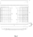
Fig.1 is a structure schematic diagram of a washing machine inner barrel of the present disclosure; -
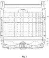
Fig. 2 is a sectional view ofFig. 1 of the present disclosure; -
Fig. 3 is a partial enlarged view ofFig. 2 of the present disclosure; -
Fig.4 is an exploded view of a barrel bottom of the washing machine inner barrel of the present disclosure; -
Fig. 5 is a stereoscopic structure diagram of a barrel bottom protective cover of the present disclosure. - Reference signs: 100- balance ring, 200- barrel body, 300-barrel bottom, 310-barrel bottom body, 311- barrel bottom body sidewall, 312- radical reinforcing rib, 313-ring rib, 314- first connecting surface, 315- third connecting surface, 316- fifth connecting surface, 317- screw column, 320- barrel bottom protective cover, 321-fourth connecting surface, 322- barrel bottom protective cover sidewall, 323- bottom wall of barrel bottom protective cover, 324- positioning and mounting part, 325- screw hole, 326- deposition positioning hole, 327- sixth connecting surface, 328- second connecting surface, 329- reinforcing rib, 330- flange structure, 331- protrusion rib, 332-water-permeable channel.
- The following is further and specific description of a washing machine inner barrel and a washing machine of the present disclosure with accompanying drawings.
- As shown in
Fig. 1 andFig. 2 , a washing machine inner barrel comprises abarrel bottom 300 and abarrel body 200 connected thereto. Thebarrel bottom 300 comprises a barrelbottom body 310 and a barrel bottomprotective cover 320. The barrel bottomprotective cover 320 is hermetically mounted on the bottom of the barrelbottom body 310 so that the entire outer surface of thebarrel bottom 310 becomes a smooth surface. - The
barrel body 200 and thebarrel bottom 300 together form a barrel structure for holding the washing clothes. Thebarrel body 200 is generally made of metal material, while thebarrel bottom 300 is generally a plastic structure. Therefore, in order to ensure the strength of thebarrel bottom 300, a series of reinforcing rib structures are arranged on the bottom of the barrelbottom body 310. - The reinforcing rib structure comprises a radical reinforcing
rib 312 and aring rib 313. The radical reinforcingrib 312 and thering rib 313 intersect to form a plurality of groove structures. - The
barrel bottom 300 of the present disclosure comprises the barrelbottom body 310 and the barrel bottomprotective cover 320. The outer surface of the barrel bottomprotective cover 320 is a smooth flat surface. The barrel bottomprotective cover 320 is hermetically connected with the bottom of the barrelbottom body 310. The barrel bottomprotective cover 320 completely covers the reinforcing rib structure so that the reinforcing rib structure is in an enclosed space. - The washing machine inner barrel of the present disclosure is particularly suitable for the washing machine having cleaning particles between the inner barrel and the outer barrel. The
barrel bottom 300 comprises two parts, namely the barrelbottom body 310 and the barrel bottomprotective cover 320. The reinforcing rib structure of the barrelbottom body 310 is covered by the barrel bottomprotective cover 320, and the outer surface of the barrel bottomprotective cover 320 is a smooth flat surface. In this way, it is more conductive to the cleaning effect of the particles on thebarrel bottom 300 of the inner barrel. The barrel bottomprotective cover 320 is hermetically connected to the bottom of the barrelbottom body 310 so that the reinforcing rib structure is in an enclosed space to prevent the washing water from entering the reinforcing rib structure, thereby substantially eliminating the problem of bacteria breeding or fouling accumulation at the reinforcing rib structure of the barrel bottom. - The barrel
bottom body 310 of the present disclosure is a ring-shaped tub body structure with a hollow bottom, which comprises a closed circular ring-shaped barrelbottom body sidewall 311 and a barrel bottom body bottom wall connected thereto. The outer contour of the barrel bottomprotective cover 320 is matched with the outer contour of the barrelbottom body 310 so that the barrelbottom body 310 is covered by the barrel bottomprotective cover 320, to cover the reinforcing rib structure. - The barrel
bottom body sidewall 311 and the barrel bottom body bottom wall of the existing the barrelbottom body 310 are provided with the reinforcing rib structure, in order to realize the hermetically connection of the barrel bottomprotective cover 320 and the bottom of the barrelbottom body 310, and to make the reinforcing rib structure in an enclosed space. - As shown in
Fig. 4 andFig. 5 , the outer side of the bottom wall of the barrelbottom body 310 is provided with a first connectingsurface 314, and the inner side of the bottom wall of the barrel bottomprotective cover 320 is provided with a second connectingsurface 328. The first connectingsurface 314 and the second connectingsurface 328 are hermetically connected. The side wall of the barrelbottom body 310 is provided with a third connectingsurface 315, and the end part of the side wall of the barrel bottomprotective cover 320 is a fourth connectingsurface 321. The third connectingsurface 315 and the fourth connectingsurface 321 are hermetically connected. In this way, it realizes the hermetically connection of two edge joints of the barrel bottomprotective cover 320 and the barrelbottom body 310 of the present disclosure, so that the reinforcing rib structure located in the two edge joints is in an enclosed space. - As shown in
Fig. 3 , the first connectingsurface 314 and the second connectingsurface 328 of the present disclosure are hermetically connected to form a sealing surface shown at the part C in the figure, and the third connectingsurface 315 and the fourth connectingsurface 321 are hermetically connected to form a connecting surface shown at the part A in the figure. The reinforcing rib structures of the barrelbottom body 310 are all located in the enclosed space between the part A and part C in the figure, completely isolated from the outside, avoids the contact of the washing water, and thereby fundamentally eliminates the breeding of bacteria or fouling accumulation at the reinforcing rib structure of the barrel bottom. - Specially, as shown in
Fig. 4 andFig. 5 , in the present disclosure, the bottom wall of the barrelbottom body 310 is provided with a first opening, the first opening extends towards the outer side of the inner barrel to form the first connectingsurface 314. The bottom wall of the barrel bottomprotective cover 320 is provided with a second opening which is corresponding to the first opening, the second opening extends towards the inner side of the inner barrel to form the second connectingsurface 328. - The first opening of the barrel
bottom body 310 is for the installation of the pulsator of the washing machine, therefore, the first opening is the innermost edge of the barrelbottom body 310. The second opening provided on the barrel bottomprotective cover 320 is to match the barrelbottom body 310 without effecting the installation of the pulsator, and the second opening is the innermost edge of the barrel bottomprotective cover 320. Therefore, in the present disclosure, the first connectingsurface 314 is provided on the first opening, and the second connectingsurface 328 is provided on the second opening, so that the innermost edge of the barrelbottom body 310 and the innermost edge of the barrel bottomprotective cover 320 are hermetically connected. - In the present disclosure, the reinforcing rib structure is arranged below the sidewall of the barrel
bottom body 310, and on the bottom wall thereof. The joint of the sidewall of the barrelbottom body 310 and the reinforcing rib structure is provided with the third connectingsurface 315, and the end part of the sidewall of the barrel bottomprotective cover 320 is the fourth connectingsurface 321. The third connectingsurface 315 and the fourth connectingsurface 321 are provided on the outermost edge of the joint of the barrelbottom body 310 and the barrel bottomprotective cover 320, so that the outermost edge of the barrelbottom body 310 and the outermost edge of the barrel bottomprotective cover 320 are hermetically connected. - The
inner barrel bottom 300 of the washing machine is also connected with the transmission shaft, and the transmission shaft achieves the rotation of the inner barrel under the driving of the motor. Since theinner barrel bottom 300 is generally made by injection molding, in order to guarantee the connection strength of theinner barrel bottom 300 and the transmission shaft, aflange structure 330 is generally installed on theinner barrel bottom 300 and made of metal material. Specifically, theflange structure 330 is installed on thebarrel bottom 300 of the present disclosure and is arranged on the outer side of the bottom wall of the barrel bottomprotective cover 320. In the present disclosure, theflange structure 330 is installed on the outer side of the bottom wall of the barrel bottomprotective cover 320, so that the installation of theflange structure 330 will not affect the sealing surface between the barrelbottom body 310 and the barrel bottomprotective cover 320, and it ensures the effect of hermetically connection. - Specifically, in the present disclosure, the barrel
bottom body 310 is the main structure of thebarrel bottom 300, while the barrel bottomprotective cover 320 is mainly used to cover the reinforcing rib structure of the barrelbottom body 310. Therefore, in order to guarantee the overall strength, the thickness of the barrelbottom body 310 is larger than that of the barrel bottomprotective cover 320. In order to guarantee the installation stability of theflange structure 330, ascrew column 317 is arranged on the bottom wall of the barrelbottom body 310, and ascrew hole 325, corresponding to thescrew column 317, is arranged on the bottom wall of the barrel bottomprotective cover 320. Theflange structure 330 is fixed on theinner barrel bottom 300 by adopting the manner of connecting the screw with thescrew column 317. - As shown in
Fig. 4 , thescrew column 317 arranged on the bottom wall of the barrelbottom body 310 is located between the reinforcing rib structures. Therefore, the installation of theflange structure 330 may cause that the washing water enters the reinforcing rib structure through thescrew hole 325. In order to further eliminate the washing water from infiltrating into the reinforcing rib structure through thescrew hole 325, the inner side of the bottom wall of the barrel bottomprotective cover 320, at the periphery of thescrew hole 325, is provided with a protrusion structure, and the end part of the protrusion structure is the sixth connectingsurface 327. The bottom wall of the barrelbottom body 310, at the periphery of thescrew column 317 is provided with a ring of ring-shaped reinforcing rib, and the end part of the ring-shaped reinforcing rib is the fifth connectingsurface 316. The sixth connectingsurface 327 and the fifth connectingsurface 316 are hermetically connected. In this way, as shown inFig. 3 , in the present disclosure, also a ring of a sealing surface B is formed at the periphery of thescrew column 317, and the reinforcing rib structure between the sealing surface B and the sealing surface A is still in a completely enclosed space, realizing the sealing of most of the reinforcing rib structure. - Further, in the present disclosure, the inner side of the bottom wall of the barrel bottom
protective cover 320, at the inner side of thescrew hole 325, is also provided with the protrusion structure, the end part of the protrusion structure is an eighth connecting surface. The bottom wall of the barrelbottom body 310, at the inner side of thescrew column 317, is provided with a ring of ring-shaped reinforcing rib, the end part of the ring-shaped reinforcing rib is a seventh connecting surface. The eighth connecting surface and the seventh connecting surface are hermetically connected. In this way, a ring of sealing surface C is also formed in the inner side of thescrew column 317, and the reinforcing rib structure between the inner side of thescrew column 317 and the sealing surface C is also sealed. Therefore, there is only a ring of reinforcing rib structure arranged on thescrew column 317 that is not completely sealed on the bottom wall of the barrelbottom body 310, and the others are all in a completely sealed state, so as to achieve the technical effect of eliminating the problem of bacteria breeding or fouling accumulation at the reinforcing rib structure of the barrel bottom. - The inner barrel of the present disclosure is rotatably arranged inside the outer barrel. Cleaning particles for cleaning the outer wall of the inner barrel and the inner wall of the outer wall is provided between the inner barrel and the outer barrel. The barrel bottom
protective cover 320 is a hollow ring-shaped cap body, and the hollow position of the barrel bottomprotective cover 320 is correspondingly plugged by theflange structure 330. Theflange structure 330, corresponding to the hollow position, is provided with a water-permeable channel 332 which is for letting the washing water flow out and blocking the entering of the cleaning particles. Specifically, theflange structure 330 of the present disclosure is of a discoid shape structure. - In the present disclosure, the water-
permeable channel 332 is to guarantee the drainage need and used for blocking the entering of the cleaning particles. As shown inFig. 4 , the water-permeable channel 332 comprises a plurality of strip slit structures arranged along the radical direction of theflange structure 330, and the width of the strip slit structure is less than the diameter of the cleaning particles. - Moreover, the
flange structure 330 is also provided with a plurality ofprotrusion ribs 331 for enhancing its overall strength. - In order to achieve the hermetically connection between the barrel
bottom body 310 and the barrel bottomprotective cover 320, the barrel bottomprotective cover 320, by means of the deposition method, is connected with the barrelbottom body 310 to be a whole. The first connectingsurface 314, the second connectingsurface 328, the third connectingsurface 315, the fourth connectingsurface 321, the fifth connectingsurface 316 and the sixth connectingsurface 327 are respectively a deposition surface. The deposition method is adopted so that each connecting surface can be deposited and connected to be a whole, guaranteeing the connection tightness and having a good sealing effect. - For the operation of the deposition techniques, in the present disclosure, the bottom wall of the barrel bottom
protective cover 320 is provided with adeposition positioning hole 326 for the deposition fixture. - Other connection ways known to one skilled in the art can be applied as long as the hermetically connection of the barrel
bottom body 310 and the barrel bottomprotective cover 320 is realized, such as bonding, bolting and installing the sealing strips on the sealing surface. - In the present disclosure, the inner wall of the barrel bottom
protective cover 320 is provided with a reinforcingrib 329 for enhancing the overall strength. There are a plurality of reinforcingribs 329 provided, and are arranged with one full circle along the radical direction of the barrel bottomprotective cover 320. - A
balance ring 100 is installed on the opening of thebarrel body 200 of the washing machine inner barrel of the present disclosure. - Another object of the present disclosure is to provide a washing machine having the above-mentioned washing machine inner barrel. The inner barrel is rotatably arranged inside the outer barrel. The cleaning particles for cleaning the outer wall of the inner barrel and the inner wall of the outer barrel are arranged between the inner barrel and the outer barrel. Therefore, after the washing machine of the present disclosure adopts the above-mentioned washing machine inner barrel, the all outer surface of the inner barrel bottom is a smooth flat structure, and the cleaning particles can better clean the inner barrel bottom.
- The foregoing is merely illustrative of the preferred embodiments of the present disclosure and is not intended to be limiting of the present disclosure. While the disclosure has been disclosed by way of example with reference to the preferred embodiments, it is not intended to be limiting of the disclosure. Any person skilled in the art will, without departing from the scope of the technical solution of the present disclosure, may make use of the technical contents of the above-mentioned tips to make some alterations or modifications to equivalent embodiments, but without departing from the scope of the technical solution of the present disclosure. Any and all modifications, equivalents, and modifications of the foregoing embodiments are within the scope of the present disclosure without departing from the spirit of the technical solution of the present disclosure in accordance with the technical details of the present disclosure.
Claims (10)
- A washing machine inner barrel, comprising a barrel bottom (300) and a barrel body (200) connected with the barrel bottom, wherein the barrel bottom (300) comprises a barrel bottom body (310) and a barrel bottom protective cover (320), the barrel bottom protective cover (320) is hermetically mounted on a bottom of the barrel bottom body (310) so that an outer surface of the barrel bottom (300) is a smooth surface.
- The washing machine inner barrel according to claim 1, wherein the bottom of the barrel bottom body (310) is provided with a reinforcing rib structure, and an outer surface of the barrel bottom protective cover (320) is the smooth surface;
the barrel bottom protective cover (320) and the bottom of the barrel bottom body (310) are hermetically connected to be a whole, the reinforcing rib structure is completely covered by the barrel bottom protective cover (320) so that the reinforcing rib structure is in an enclosed space. - The washing machine inner barrel according to claim 2, wherein an outer side of a bottom wall of the barrel bottom body (310) is provided with a first connecting surface (314), an inner side of a bottom wall of the barrel bottom protective cover (320) is provided with a second connecting surface (328), and the first connecting surface (314) and the second connecting surface (328) are hermetically connected;
a sidewall of the barrel bottom body (310) is provided with a third connecting surface (315), an end part of a sidewall of the barrel bottom protective cover (320) is a fourth connecting surface (321), and the third connecting surface (315) and the fourth connecting surface (321) are hermetically connected. - The washing machine inner barrel according to claim 3, wherein the bottom wall of the barrel bottom body (310) is provided with a first opening, and the first opening extends towards an outer side of the inner barrel to form the first connecting surface (314),
the bottom wall of the barrel bottom protective cover (320) is provided with a second opening which is corresponding to the first opening, and the second opening extends towards an inner side of the inner barrel to form the second connecting surface (328). - The washing machine inner barrel according to claim 3, wherein a reinforcing rib structure is arranged below the sidewall and on the bottom wall of the barrel bottom body (310), a joint of the reinforcing rib structure and the sidewall of the barrel bottom body (310) is provided with the third connecting surface (315), the end part of the sidewall of the barrel bottom protective cover (320) is the fourth connecting surface (321).
- The washing machine inner barrel according to any of claims from 1 to 5, wherein a flange structure (330) is installed on the barrel bottom (300), and arranged on an outer side of the bottom wall of the barrel bottom protective cover (320);
preferably, a screw column (317) is arranged on the bottom wall of the barrel bottom body (310),
a screw hole (325), corresponding to the screw column (317), is arranged in the bottom wall of the barrel bottom protective cover (320),
the flange structure (330) is connected fixedly to the inner barrel bottom (300) by the screw and the screw column (317). - The washing machine inner barrel according to claim 6, wherein a protrusion structure is provided on the inner side of the bottom wall of the barrel bottom protective cover (320), and at a periphery of the screw hole (325), an end part of the protrusion structure is a sixth connecting surface (327),
the bottom wall of the barrel bottom body (310), at a periphery of the screw column (317), is provided with a ring of ring-shaped reinforcing rib, the end part of the ring-shaped reinforcing rib is a fifth connecting surface (316),
the sixth connecting surface (327) and the fifth connecting surface (316) are hermetically connected. - The washing machine inner barrel according to claim 7, wherein the barrel bottom protective cover (320) is connected with the barrel bottom body (310) to be a whole by means of the deposition method, the first connecting surface (314), the second connecting surface (328), the third connecting surface (315), the fourth connecting surface (321), the fifth connecting surface (316) and the sixth connecting surface (327) are respectively a deposition surface.
- The washing machine inner barrel according to claim 6, wherein the inner barrel is rotatably arranged inside an outer barrel,
cleaning particles, for cleaning an outer wall of the inner barrel and an inner wall of the outer barrel, is arranged between the inner barrel and the outer barrel;
the barrel bottom protective cover (320) is a hollow ring-shaped cover body, a hollow position of the barrel bottom protective cover (320) is correspondingly plugged by the flange structure (330);
a part of the flange structure (330), corresponding to the hollow position, is provided with a water-permeable channel (332) which is for allowing washing water to flow out and avoiding the cleaning particles from entering in the inner barrel. - A washing machine with the inner barrel according to any of claims from 1 to 9.
Applications Claiming Priority (2)
| Application Number | Priority Date | Filing Date | Title |
|---|---|---|---|
| CN201510802100.0A CN106757992A (en) | 2015-11-19 | 2015-11-19 | A kind of washing machine inner tub and washing machine |
| PCT/CN2016/106371 WO2017084613A1 (en) | 2015-11-19 | 2016-11-18 | Washing machine inner barrel and washing machine |
Publications (2)
| Publication Number | Publication Date |
|---|---|
| EP3378985A1 true EP3378985A1 (en) | 2018-09-26 |
| EP3378985A4 EP3378985A4 (en) | 2018-11-21 |
Family
ID=58717387
Family Applications (1)
| Application Number | Title | Priority Date | Filing Date |
|---|---|---|---|
| EP16865790.6A Withdrawn EP3378985A4 (en) | 2015-11-19 | 2016-11-18 | Washing machine inner barrel and washing machine |
Country Status (6)
| Country | Link |
|---|---|
| US (1) | US20180298545A1 (en) |
| EP (1) | EP3378985A4 (en) |
| JP (1) | JP2018538034A (en) |
| KR (1) | KR20180084121A (en) |
| CN (1) | CN106757992A (en) |
| WO (1) | WO2017084613A1 (en) |
Families Citing this family (4)
| Publication number | Priority date | Publication date | Assignee | Title |
|---|---|---|---|---|
| CN109554895A (en) * | 2019-01-08 | 2019-04-02 | 惠而浦(中国)股份有限公司 | A kind of multiple spray equipment for roller washing machine |
| CN112239928A (en) * | 2019-07-17 | 2021-01-19 | 青岛海尔洗衣机有限公司 | Clothes treatment equipment |
| TWI748877B (en) * | 2021-02-23 | 2021-12-01 | 台灣松下電器股份有限公司 | Washing machine turntable |
| CN117512945B (en) * | 2023-11-16 | 2025-09-19 | 珠海格力电器股份有限公司 | Washing and drying machine |
Family Cites Families (27)
| Publication number | Priority date | Publication date | Assignee | Title |
|---|---|---|---|---|
| JPS6042756B2 (en) * | 1979-06-11 | 1985-09-25 | 松下電器産業株式会社 | dehydration washing machine |
| JPS5874489U (en) * | 1981-11-14 | 1983-05-19 | 株式会社東芝 | Dehydration/washing machine |
| JPH0739679A (en) * | 1993-08-02 | 1995-02-10 | Matsushita Electric Ind Co Ltd | Automatic washing machine |
| KR960037494U (en) * | 1995-05-26 | 1996-12-16 | Power train of washing machine | |
| JP3253580B2 (en) * | 1997-12-26 | 2002-02-04 | 三洋電機株式会社 | Two-tub washing machine |
| JPH11276774A (en) * | 1998-03-27 | 1999-10-12 | Nippon Kentetsu Co Ltd | Washing and dewatering tub structure of washing machine |
| US6286344B1 (en) * | 1999-02-04 | 2001-09-11 | Lg Electronics Inc. | Washing machine with tilted tub assembly |
| JP2001038097A (en) * | 1999-07-28 | 2001-02-13 | Hitachi Ltd | Washing machine easy to recycle |
| KR100513033B1 (en) * | 2003-03-03 | 2005-09-05 | 엘지전자 주식회사 | Washing machine with lower balancer |
| JP2005304715A (en) * | 2004-04-20 | 2005-11-04 | Hitachi Ltd | Electric washing machine |
| WO2007126171A2 (en) * | 2006-05-02 | 2007-11-08 | Lg Electronics Inc. | Washing machine |
| WO2007132955A1 (en) * | 2006-05-12 | 2007-11-22 | Lg Electronics Inc. | A tub for a washing machine with a bearing housing inserted therein |
| KR20080071427A (en) * | 2007-01-30 | 2008-08-04 | 엘지전자 주식회사 | washer |
| ES2375587T3 (en) * | 2007-02-21 | 2012-03-02 | Meccanica Generale S.R.L. | WASHING MACHINE TANK PROVIDED WITH AN EXTERNAL REINFORCEMENT COAT ON THE LOWER WALL. |
| WO2010077108A2 (en) * | 2008-12-31 | 2010-07-08 | 엘지전자 주식회사 | Laundry machine |
| CN202430494U (en) * | 2011-12-27 | 2012-09-12 | 海尔集团公司 | Washing machine inner drum and washing machine |
| CN102733147B (en) * | 2012-06-08 | 2017-09-29 | 青岛海尔洗衣机有限公司 | A kind of washing machine inner tub and washing machine with automatically cleaning bucket wall function |
| WO2013181901A1 (en) * | 2012-06-08 | 2013-12-12 | 海尔集团公司 | Self-cleaning washing machine and control method |
| CN202865624U (en) * | 2012-06-08 | 2013-04-10 | 海尔集团公司 | Washing machine inner barrel with self cleaning barrel wall function and washing machine |
| CN103820974A (en) * | 2012-11-16 | 2014-05-28 | 海尔集团公司 | Automatic cleaning washer |
| CN103966796A (en) * | 2013-01-31 | 2014-08-06 | 顾粟裕 | Inner barrel device of washing-dewatering all-in-one machine |
| WO2014169679A1 (en) * | 2013-04-17 | 2014-10-23 | 海尔集团公司 | Integrated structure of internal barrel and impeller, washing machine and washing method |
| CN104452174B (en) * | 2013-09-13 | 2018-09-04 | 青岛海尔洗衣机有限公司 | A kind of water leakage preventing washing machine |
| EP3168354B1 (en) * | 2014-07-07 | 2019-07-03 | Qingdao Haier Washing Machine Co., Ltd. | Flange structure at the bottom of an inner drum of a washing machine, and washing machine |
| KR102252508B1 (en) * | 2015-01-05 | 2021-05-14 | 엘지전자 주식회사 | laundry machine |
| CN204715076U (en) * | 2015-04-09 | 2015-10-21 | 山东小鸭集团家电有限公司 | A kind of washing machine inner tub |
| KR102418217B1 (en) * | 2015-08-26 | 2022-07-08 | 삼성전자주식회사 | Washing machine |
-
2015
- 2015-11-19 CN CN201510802100.0A patent/CN106757992A/en active Pending
-
2016
- 2016-11-18 WO PCT/CN2016/106371 patent/WO2017084613A1/en not_active Ceased
- 2016-11-18 KR KR1020187017332A patent/KR20180084121A/en not_active Ceased
- 2016-11-18 US US15/777,264 patent/US20180298545A1/en not_active Abandoned
- 2016-11-18 EP EP16865790.6A patent/EP3378985A4/en not_active Withdrawn
- 2016-11-18 JP JP2018523764A patent/JP2018538034A/en active Pending
Also Published As
| Publication number | Publication date |
|---|---|
| JP2018538034A (en) | 2018-12-27 |
| EP3378985A4 (en) | 2018-11-21 |
| CN106757992A (en) | 2017-05-31 |
| US20180298545A1 (en) | 2018-10-18 |
| KR20180084121A (en) | 2018-07-24 |
| WO2017084613A1 (en) | 2017-05-26 |
Similar Documents
| Publication | Publication Date | Title |
|---|---|---|
| CN107475986B (en) | washing machine | |
| US10526740B2 (en) | Self-cleaning drum washing machine | |
| US20180298545A1 (en) | Washing machine inner barrel and washing machine | |
| CN102425047B (en) | The automatic washing machine of automatic fitration line bits | |
| CN109208269B (en) | Washing machine | |
| CN204105899U (en) | Automatic ground washing machine | |
| CN209789781U (en) | Cleaning barrel and cleaning tool with same | |
| CN204105901U (en) | Foul water tank and automatic ground washing machine thereof | |
| CN105525480A (en) | Pulsator washing machine having heating function | |
| CN202430494U (en) | Washing machine inner drum and washing machine | |
| CN109440393B (en) | a washing machine | |
| CN107916531B (en) | A washing machine gimbal, inner tub and washing machine | |
| CN110241561B (en) | Washing barrel of washing machine and washing machine with washing barrel | |
| WO2022183896A1 (en) | Drum washing machine | |
| CN106667399A (en) | Electric dish washer | |
| CN109097951B (en) | Washing machine | |
| WO2019010851A1 (en) | Dishwasher door flow guiding device and dishwasher | |
| CN210766008U (en) | Clothes treating device | |
| CN110952269A (en) | Drum washing machine | |
| CN102433714A (en) | Washing machine inner barrel convenient to clean and washing machine | |
| CN222771152U (en) | Washing bucket assembly and washing equipment | |
| CN210333506U (en) | Medicinal material self-cleaning equipment | |
| CN209923617U (en) | Sock washing machine | |
| CN106273065A (en) | Working of plastics Water-saving washing device | |
| CN205741298U (en) | A kind of High-efficient Water washing machine |
Legal Events
| Date | Code | Title | Description |
|---|---|---|---|
| STAA | Information on the status of an ep patent application or granted ep patent |
Free format text: STATUS: THE INTERNATIONAL PUBLICATION HAS BEEN MADE |
|
| PUAI | Public reference made under article 153(3) epc to a published international application that has entered the european phase |
Free format text: ORIGINAL CODE: 0009012 |
|
| STAA | Information on the status of an ep patent application or granted ep patent |
Free format text: STATUS: REQUEST FOR EXAMINATION WAS MADE |
|
| 17P | Request for examination filed |
Effective date: 20180614 |
|
| AK | Designated contracting states |
Kind code of ref document: A1 Designated state(s): AL AT BE BG CH CY CZ DE DK EE ES FI FR GB GR HR HU IE IS IT LI LT LU LV MC MK MT NL NO PL PT RO RS SE SI SK SM TR |
|
| AX | Request for extension of the european patent |
Extension state: BA ME |
|
| A4 | Supplementary search report drawn up and despatched |
Effective date: 20181018 |
|
| RIC1 | Information provided on ipc code assigned before grant |
Ipc: D06F 39/12 20060101AFI20181012BHEP Ipc: D06F 35/00 20060101ALI20181012BHEP Ipc: D06F 37/12 20060101ALI20181012BHEP Ipc: D06F 37/26 20060101ALI20181012BHEP |
|
| DAV | Request for validation of the european patent (deleted) | ||
| DAX | Request for extension of the european patent (deleted) | ||
| STAA | Information on the status of an ep patent application or granted ep patent |
Free format text: STATUS: THE APPLICATION IS DEEMED TO BE WITHDRAWN |
|
| 18D | Application deemed to be withdrawn |
Effective date: 20190518 |