EP3378984B1 - Clutch assembly of washing machine - Google Patents
Clutch assembly of washing machine Download PDFInfo
- Publication number
- EP3378984B1 EP3378984B1 EP17736146.6A EP17736146A EP3378984B1 EP 3378984 B1 EP3378984 B1 EP 3378984B1 EP 17736146 A EP17736146 A EP 17736146A EP 3378984 B1 EP3378984 B1 EP 3378984B1
- Authority
- EP
- European Patent Office
- Prior art keywords
- pulsator
- drum
- shaft
- coupling
- washing machine
- Prior art date
- Legal status (The legal status is an assumption and is not a legal conclusion. Google has not performed a legal analysis and makes no representation as to the accuracy of the status listed.)
- Active
Links
Images










Classifications
-
- D—TEXTILES; PAPER
- D06—TREATMENT OF TEXTILES OR THE LIKE; LAUNDERING; FLEXIBLE MATERIALS NOT OTHERWISE PROVIDED FOR
- D06F—LAUNDERING, DRYING, IRONING, PRESSING OR FOLDING TEXTILE ARTICLES
- D06F37/00—Details specific to washing machines covered by groups D06F21/00 - D06F25/00
- D06F37/30—Driving arrangements
- D06F37/40—Driving arrangements for driving the receptacle and an agitator or impeller, e.g. alternatively
-
- D—TEXTILES; PAPER
- D06—TREATMENT OF TEXTILES OR THE LIKE; LAUNDERING; FLEXIBLE MATERIALS NOT OTHERWISE PROVIDED FOR
- D06F—LAUNDERING, DRYING, IRONING, PRESSING OR FOLDING TEXTILE ARTICLES
- D06F37/00—Details specific to washing machines covered by groups D06F21/00 - D06F25/00
- D06F37/30—Driving arrangements
- D06F37/304—Arrangements or adaptations of electric motors
-
- F—MECHANICAL ENGINEERING; LIGHTING; HEATING; WEAPONS; BLASTING
- F16—ENGINEERING ELEMENTS AND UNITS; GENERAL MEASURES FOR PRODUCING AND MAINTAINING EFFECTIVE FUNCTIONING OF MACHINES OR INSTALLATIONS; THERMAL INSULATION IN GENERAL
- F16D—COUPLINGS FOR TRANSMITTING ROTATION; CLUTCHES; BRAKES
- F16D11/00—Clutches in which the members have interengaging parts
- F16D11/14—Clutches in which the members have interengaging parts with clutching members movable only axially
-
- H—ELECTRICITY
- H02—GENERATION; CONVERSION OR DISTRIBUTION OF ELECTRIC POWER
- H02K—DYNAMO-ELECTRIC MACHINES
- H02K7/00—Arrangements for handling mechanical energy structurally associated with dynamo-electric machines, e.g. structural association with mechanical driving motors or auxiliary dynamo-electric machines
- H02K7/10—Structural association with clutches, brakes, gears, pulleys or mechanical starters
- H02K7/108—Structural association with clutches, brakes, gears, pulleys or mechanical starters with friction clutches
-
- D—TEXTILES; PAPER
- D06—TREATMENT OF TEXTILES OR THE LIKE; LAUNDERING; FLEXIBLE MATERIALS NOT OTHERWISE PROVIDED FOR
- D06F—LAUNDERING, DRYING, IRONING, PRESSING OR FOLDING TEXTILE ARTICLES
- D06F21/00—Washing machines with receptacles, e.g. perforated, having a rotary movement, e.g. oscillatory movement
-
- D—TEXTILES; PAPER
- D06—TREATMENT OF TEXTILES OR THE LIKE; LAUNDERING; FLEXIBLE MATERIALS NOT OTHERWISE PROVIDED FOR
- D06F—LAUNDERING, DRYING, IRONING, PRESSING OR FOLDING TEXTILE ARTICLES
- D06F37/00—Details specific to washing machines covered by groups D06F21/00 - D06F25/00
- D06F37/02—Rotary receptacles, e.g. drums
- D06F37/12—Rotary receptacles, e.g. drums adapted for rotation or oscillation about a vertical axis
-
- D—TEXTILES; PAPER
- D06—TREATMENT OF TEXTILES OR THE LIKE; LAUNDERING; FLEXIBLE MATERIALS NOT OTHERWISE PROVIDED FOR
- D06F—LAUNDERING, DRYING, IRONING, PRESSING OR FOLDING TEXTILE ARTICLES
- D06F37/00—Details specific to washing machines covered by groups D06F21/00 - D06F25/00
- D06F37/20—Mountings, e.g. resilient mountings, for the rotary receptacle, motor, tub or casing; Preventing or damping vibrations
- D06F37/24—Mountings, e.g. resilient mountings, for the rotary receptacle, motor, tub or casing; Preventing or damping vibrations in machines with a receptacle rotating or oscillating about a vertical axis
-
- D—TEXTILES; PAPER
- D06—TREATMENT OF TEXTILES OR THE LIKE; LAUNDERING; FLEXIBLE MATERIALS NOT OTHERWISE PROVIDED FOR
- D06F—LAUNDERING, DRYING, IRONING, PRESSING OR FOLDING TEXTILE ARTICLES
- D06F37/00—Details specific to washing machines covered by groups D06F21/00 - D06F25/00
- D06F37/30—Driving arrangements
- D06F37/36—Driving arrangements for rotating the receptacle at more than one speed
- D06F37/38—Driving arrangements for rotating the receptacle at more than one speed in opposite directions
Definitions
- the present invention relates to a washing machine, and more particularly, to a washing machine that improves the structure of a clutch assembly that transmits power of a motor.
- a washing machine is a machine for washing clothing using electric power.
- the washing machine generally includes a tub for storing wash water, a drum rotatably installed in a water tank, a pulsator rotatably installed on the bottom of the drum, a motor for rotationally driving the pulsator, and a clutch assembly for transmitting the power of the motor to the drum and the pulsator.
- the pulsator rotates while laundry and water are contained in the drum, and contaminants are separated from the laundry by a water stream formed in the drum, and during the rinse cycle, the drum and the pulsator rotate together so that the separated contaminants are dissolved in the water.
- the conventional washing machine is equipped with a clutch assembly that converts a mode for transmitting the power of the motor to the pulsator to a mode for transmitting the power of the motor to both the pulsator and the drum.
- WO 2004/069020 A2 , WO 2015/188683 A1 and US 2012/222454 A1 are all directed to washing machines comprising a pulsator located inside a drum and directly connected to a motor and a clutch for selectively transmitting power to the drum.
- the clutch assembly mounted in the conventional washing machine does not have a mechanism for transmitting the power of the motor only to the drum.
- a washing machine includes a tub for storing water, a drum rotatably disposed in the tub, a pulsator provided within the drum, the pulsator being rotatable independently of the drum, a motor for generating power and a clutch assembly for transmitting the power of the motor to the drum or the pulsator.
- the clutch assembly includes a pulsator driving portion coupled to the pulsator to transmit the power of the motor to the pulsator and a coupling selectively coupled to the pulsator driving portion such that the power of the motor is not transmitted to the pulsator.
- the clutch assembly may transfer the power of the motor to the drum or the pulsator by raising or lowering the coupling.
- the washing machine further includes a drum driving portion coupled to the drum to transmit the power of the motor to the drum.
- the driving direction of the drum is opposite to the rotating direction of the motor when the power of the motor is transmitted to the drum driving portion and the power of the motor is not transmitted to the pulsator driving portion.
- the washing machine may further include a sun gear for receiving the power of the motor; and a plurality of planetary gears disposed around the sun gear to engage the sun gear.
- the pulsator driving portion preferably includes a planetary gear connecting portion connecting a plurality of planetary gear shafts passing through a rotation center of each of the plurality of planetary gears.
- the drum driving portion may include a ring gear surrounding the plurality of planetary gears and engaging the plurality of planetary gears.
- the coupling is preferably adapted to restrain the rotation of the planetary gear connecting portion so that the plurality of planetary gears do not revolve about the sun gear so that the power is not transmitted to the pulsator.
- the clutch assembly includes a driving shaft receiving the power from the motor, a pulsator shaft surrounding the driving shaft and coupled to the pulsator to transmit the power of the motor to the pulsator, pulsator shaft teeth formed on the outer periphery of the pulsator shaft and a coupling engaged with the pulsator shaft teeth to selectively restrict the rotation of the pulsator shaft.
- the clutch assembly may include a drum shaft surrounding the pulsator shaft and coupled to the drum to transmit the power of the motor to the drum and drum shaft teeth formed on an outer circumference of the drum shaft.
- the coupling includes a pulsator restricting portion engaging the pulsator shaft teeth and a drum coupling portion engaging the drum shaft teeth.
- the power of the motor is transmitted to the drum via the coupling when the drum coupling portion is engaged with the drum shaft teeth.
- the clutch assembly raises or lowers the coupling such that the coupling selectively engages the pulsator shaft teeth.
- the washing machine further includes a sun gear formed at one end of the driving shaft, a plurality of planetary gears disposed around the sun gear and engaging the sun gear and a ring gear surrounding the plurality of planetary gears and meshing with the plurality of planetary gears.
- a sun gear formed at one end of the driving shaft
- a plurality of planetary gears disposed around the sun gear and engaging the sun gear
- a ring gear surrounding the plurality of planetary gears and meshing with the plurality of planetary gears.
- the washing machine further includes a driving shaft including a sun gear for receiving the power from the motor, a plurality of planetary gears disposed around the sun gear and engaging the sun gear and a ring gear surrounding the plurality of planetary gears and configured to engage with the plurality of planetary gears.
- the pulsator driving portion rotates as the plurality of planetary gears rotate about the sun gear along the ring gear.
- the washing machine further comprises a coupling for selectively restricting the rotation of the pulsator driving portion to prevent revolution of the plurality of planetary gears.
- the washing machine may further include a drum driving portion coupled to the drum to transmit the power to the drum.
- the drum driving portion is engaged with the ring gear to rotate integrally.
- the coupling selectively restrains the rotation of the pulsator driving portion by raising or lowering the coupling.
- the operating mode of the washing machine can be varied by an improved clutch assembly.
- the washing machine is operated by appropriately combining a pulsator rotation mode, drum rotation mode, and pulsator and drum simultaneous rotation mode during washing or rinsing, there is an advantage in that the washing power is improved and water consumption is reduced.
- first means “first,” “second,” etc.
- these elements should not be limited by these terms. These terms are only used to distinguish one element from another. For example, a first element could be termed a second element, and, similarly, a second element could be termed a first element without departing from the scope of the present invention.
- the term “and/or” includes any and all combinations of one or more of the associated listed items.
- FIG. 1 is a cross-sectional view of a washing machine according to an embodiment of the present invention.
- a washing machine 1 includes a cabinet 20 for forming an outer appearance, a tub 30 disposed inside the cabinet 20 for storing wash water, a drum 40 disposed rotatably, and a pulsator 45 disposed inside the drum 40 to generate a water stream.
- An inlet 22 is formed in the upper part of the cabinet 20 to allow laundry to be introduced into the drum 40.
- the inlet 22 is opened and closed by a door 21 installed on the upper part of the cabinet 20.
- the tub 30 is supported by the cabinet 20 by a suspension device 31 connecting the lower outer side of the tub 30 and the upper side of the cabinet 20.
- the vibration generated in the tub 30 during washing or dehydrating by the suspension device 31 is prevented from being transmitted to the cabinet 20.
- a water supply pipe 51 for supplying washing water to the tub 30 is installed at an upper portion of the tub 30.
- One side of the water supply pipe 51 is connected to an external water source (not shown), and the other side of the water supply pipe 51 is connected to a detergent supply pipe 50.
- Water supplied through the water supply pipe 51 is supplied to the inside of the tub 30 together with the detergent via the detergent supply pipe 50.
- a water supply valve 52 is installed in the water supply pipe 51 to control the supply of water.
- a plurality of dehydration holes 41 are provided on the side of the drum 40 to communicate with the inner space of the drum 40 and the inner space of the tub 30.
- a balancer 42 can be mounted on the upper portion of the drum 40 so that an unbalanced load generated in the drum 40 during the high speed rotation of the drum 40 is offset and the drum 40 can be stably rotated.
- the pulsator 45 is rotated forward or reverse to generate a water flow, and the laundry in the drum 40 is stirred together with the washing water by the water flow.
- a drainage hole 60 is formed at the bottom of the tub 30 to discharge the washing water stored in the tub 30 and a first drain pipe 61 is connected to the drainage hole 60.
- the first drain pipe 61 is provided with a drain valve 62 for interrupting drainage.
- the outlet of the drain valve 62 is connected to a second drain pipe 63 for discharging the wash water to the outside.
- the drain valve 62 may be provided in various configurations such as a solenoid device or a link device connected to an electric motor.
- a motor 70 for generating a driving force by receiving power is disposed at a lower end of the tub 30.
- the motor 70 consists of a circular stator 71 and a rotor 72 disposed on the outer periphery of the stator 71.
- a shaft hole 75 is formed at the center of the rotor 72 so that a shaft or a clutch boss 180 engaged with a serration 77 formed on the inner circumferential surface of the shaft hole 75 is rotated.
- a clutch assembly 100 is disposed between the motor 70 and the tub 30 to selectively transmit the driving force of the motor 70 to the drum 40 and the pulsator 45.
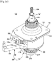
- FIG. 2A is a perspective view of a clutch assembly according to an embodiment of the present invention
- FIG. 2B is a bottom perspective view of a clutch assembly and a rotor according to an embodiment of the present invention
- FIG. 3 is a perspective view of a clutch assembly according to an embodiment of the present invention.
- the clutch assembly 100 receives power from the motor 70 and is adapted to selectively transmit a driving force to at least one of the pulsator 45 and the drum 40.
- the clutch assembly 100 includes a housing 110 that is configured to protect its internal configuration.
- the housing 110 is divided into an upper housing 112 and a lower housing 114.
- a portion of a driving shaft 120 protrudes below the lower housing 114 and a portion of a drum driving portion 140 and a portion of a pulsator drive portion 130 protrude above the upper housing 112.
- the clutch assembly 100 includes the driving shaft 120, the pulsator drive portion 130, the drum driving portion 140, and the clutch boss 180.
- the clutch boss 180 may include a boss hole 183 formed in the center portion, a circular hub 182 surrounding the boss hole 183 and boss teeth 184 formed along the periphery of the hub 182.
- the clutch boss 180 is a component to which the driving force of the motor 70 is primarily transmitted and a boss gear 187 corresponding to the serration 77 provided on the inner circumferential surface of the shaft hole 75 of the rotor 72 is formed on the outer periphery of the hub 182 protruding downward. That is, the clutch boss 180 is always rotated integrally with the motor 70.
- the boss hole 183 is formed to have a polygonal cross-section, and functions to transmit power to the driving shaft 120 coupled to the boss hole 183. The detailed configuration of the clutch boss 180 will be described later.
- the driving shaft 120 is connected to the clutch boss 180 so that the power generated by the motor 70 is transmitted to the pulsator drive portion 130 or the drum driving portion 140.
- the driving shaft 120 is a rod shaft and includes a boss engaging portion 126 at one end for engaging the clutch boss 180 and a serration type gear at the other end that functions as a sun gear 122 of a planetary gear assembly 150.
- the boss engaging portion 126 has a polygonal cross-section corresponding to the boss hole 183 and is fitted in the boss hole 183. Thus, the driving shaft 120 is always rotated integrally with the motor 70.
- the pulsator drive portion 130 may be conveniently divided into a lower pulsator shaft 132 and an upper pulsator shaft 134.
- the lower pulsator shaft 132 and the upper pulsator shaft 134 do not operate independently but rotate integrally.
- the lower pulsator shaft 132 is a cylindrical shaft whose center is hollow and the driving shaft 120 can be inserted into the hollow portion of the lower pulsator shaft 132.
- Pulsator shaft teeth 133 may be provided on the lower circumference of the lower pulsator shaft 132.
- the pulsator shaft teeth 133 are serration-shaped in such a manner that a plurality of projections are spaced apart along the outer circumferential surface of the lower pulsator shaft 132 and are selectively engaged with a pulsator shaft restricting portion 164 of a coupling 160 to be described later.
- An upper portion of the lower pulsator shaft 132 is provided with a lower planetary gear connecting portion 136 on which a plurality of planetary gears 152 are mounted and the lower planetary gear connecting portion 136 engages with an upper planetary gear connecting portion 135 disposed thereabout with the planetary gears 152 therebetween.
- the upper pulsator shaft 134 is coupled to the center of the upper planetary gear connecting portion 135 and the pulsator 45 is coupled to one end of the upper pulsator shaft 134 to rotate the pulsator 45.
- the drum driving portion 140 can be divided into a lower drum shaft 142 and an upper drum shaft 144 for convenience.
- the lower drum shaft 142 and the upper drum shaft 144 do not operate independently but rotate integrally.
- the lower drum shaft 142 is a cylindrical shaft whose center is hollow and the lower pulsator shaft 132 can be inserted into the hollow portion of the lower drum shaft 142. Accordingly, the lower pulsator shaft 132 surrounds the driving shaft 120 located at the center, and the lower drum shaft 142 encloses the lower pulsator shaft 132.
- Drum shaft teeth 143 may be provided on the outer periphery of the lower end of the lower drum shaft 142.
- the drum shaft teeth 143 are of a serration type in which a plurality of protrusions are spaced apart along the outer peripheral surface of the lower drum shaft 142. As shown in FIG. 5 , the drum shaft teeth 143 are located above the pulsator shaft teeth 133.
- the drum shaft teeth 143 can be selectively engaged with a drum shaft coupling portion 168 of the coupling 160 described below. When the lower drum shaft 142 is engaged with the coupling 160, the power of the motor is transmitted to the drum driving portion 140 through the coupling 160.
- a gearbox base 146b in the form of a flange is provided at the upper end of the lower drum shaft 142 so that the upper surface of the gearbox base 146b faces the lower surface of the lower planetary gear connecting portion 136.
- a lubricant such as grease is applied between the upper surface of the gearbox base 146b and the lower surface of the lower planetary gear connecting portion 136 to enable the relative rotation of the lower drum shaft 142 with respect to the lower pulsator shaft 132.
- the upper drum shaft 144 includes a gearbox 146 that is coupled onto the gearbox base 146b of the lower drum shaft 142.
- a drum coupling portion 147 is provided on the side of the upper drum shaft 144 opposite to the gearbox 146 and coupled to the drum 40 so that the power of the motor 70 is transmitted to the drum 40.
- the upper drum shaft 144 is a cylindrical shaft whose center is hollow, and the upper pulsator shaft 134 can be inserted into the hollow portion of the upper drum shaft 144. Since the upper drum shaft 144 and the upper pulsator shaft 134 are spaced apart from each other so as not to contact each other, they can rotate independently of each other.
- the upper pulsator shaft 134 protrudes higher than the drum coupling portion 147 of the upper drum shaft 144 and is coupled to the pulsator 45.
- FIG. 7 is a front view of a planetary gear assembly according to an embodiment of the present invention.
- the planetary gear assembly 150 is connected to the driving shaft 120, the drum driving portion 140, and the pulsator drive portion 130 and the driving force is transmitted from the driving shaft 120 to the driving portion of at least one of the drum driving portion 140 and the pulsator drive portion 130.
- the planetary gear assembly 150 is disposed within the gearbox 146 that constitutes part of the drum driving portion 140.
- the gearbox 146 includes a cylindrical gearbox body 146a having a larger diameter than the upper drum shaft 144 below the upper drum shaft 144 and a gearbox base 146b formed in the form of a flange on the lower drum shaft 142.
- the planetary gear assembly 150 may include the sun gear 122, the plurality of planetary gears 152, and a ring gear 154.
- the rotation of the sun gear 122 causes the planetary gears 152 engaged with the sun gear 122 to rotate or revolve and the ring gear 154 is rotated about the same axis as a rotation axis X of the sun gear 122 by the rotation of the planetary gears 152.
- the rotation of the planetary gears 152 means that each planetary gear rotates around each rotation axis (x1, x2, x3, x4) and the rotation of the planetary gears 152 means that the rotation axes (x1, x2, x3, x4) of each planetary gear rotate around the rotation axis X of the sun gear.
- the revolution of the planetary gears 152 involves the rotation of the planetary gears 152. That is, when the rotation of the ring gear 154 is constrained, the planetary gears 152 are engaged with the ring gear 154 to rotate about the sun gear 122 by the rotation of the planetary gears 152. On the other hand, when the revolution of the planetary gears 152 is constrained, the ring gear 154 is rotated by the rotation of the planetary gears 152.
- the sun gear 122 may be provided at one end of the driving shaft 120. That is, the driving shaft 120 may include the sun gear 122 provided in a serration form on the outer circumferential surface opposite to the side coupled with the clutch boss 180.
- the driving force of the motor can be transmitted to the plurality of planetary gears 152 and the ring gear 154 through the sun gear 122 of the driving shaft 120.
- the plurality of planetary gears 152 may be coupled to the pulsator drive portion 130. In other words, as the planetary gears 152 revolve about the sun gear 122, the rotational force is transmitted to the upper pulsator shaft 134.
- the pulsator drive portion 130 may include the pair of planetary gear connecting portions 135 and 136 connecting a plurality of planetary gear shafts 152a that are the rotational centers of each of the plurality of planetary gears 152.
- the pair of planetary gear connecting portions 135 and 136 rotatably support one end and the other end of the plurality of planetary gear shafts 152a so that the planetary gears 152 rotate about the rotation axis X when they revolve.
- the planetary gear connecting portions 135 and 136 may be composed of the upper planetary gear connecting portion 135 and the lower planetary gear connecting portion 136.
- the center of the upper planetary gear connecting portion 135 is connected to the upper pulsator shaft 134 and the center of the lower planetary gear connecting portion 136 is connected to the lower pulsator shaft 132.
- the upper planetary gear connecting portion 135 is formed integrally with the upper pulsator shaft 134
- the lower planetary gear connecting portion 136 is formed integrally with the lower pulsator shaft 132.
- the ring gear 154 may be connected to the drum driving portion 140.
- the ring gear 154 surrounds the plurality of planetary gears 152 and has the same rotational axis as the sun gear 122. That is, the serration formed inside the ring gear 154 is provided to rotate in engagement with the serration formed on the outer periphery of the planetary gears 152.
- the outer circumferential surface of the ring gear 154 is closely fixed to the inner circumferential surface of the gearbox body 146a so that the ring gear 154 and the gearbox body 146a are integrally rotated.
- the driving force transmitted to the ring gear 154 can be transmitted to the drum driving portion 140 through this configuration.
- the ring gear 154 and the gearbox body 146a of the drum driving portion 140 may be integrally formed.
- FIG. 8 is a top perspective view of a coupling according to an embodiment of the present invention
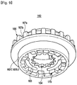
- FIG. 9 is a bottom perspective view of a coupling according to an embodiment of the present invention
- FIG. 10 is a sectional view of a coupling according to an embodiment of the present invention.
- the clutch assembly 100 can be rotated in a first, second or third mode by restricting the rotation of the lower pulsator shaft 132 or transmitting power to the lower drum shaft 142 depending on the position of the coupling 160.
- the driving shaft 120, the lower drum shaft 142, and the lower pulsator shaft 132 have the same rotation axis X and by changing the position of the coupling 160 in the direction of the rotation axis X, a rotational force can be transmitted to the lower drum shaft 142 or the rotation of the lower pulsator shaft 132 can be restrained.
- the coupling 160 may include a cylindrical coupling body 162 having a hollow portion.
- the driving shaft 120, the lower pulsator shaft 132, and the lower drum shaft 142 may pass through the hollow portion of the coupling body 162.
- the coupling body 162 can be divided into an upper body 162a and a lower body 162b.
- the drum shaft coupling portion 168 is provided on the inner peripheral surface of the upper body 162a and the pulsator shaft restricting portion 164 and a coupling gear 170 are provided on the inner side of the lower body 162b.
- the diameter of the lower drum shaft 142 is bigger than the diameter of the lower pulsator shaft 132.
- the inner diameter of the drum shaft coupling portion 168 corresponding to the lower drum shaft 142 should be formed larger than the inner diameter of the pulsator shaft restricting portion 164 corresponding to the lower pulsator shaft 132.
- the lower body 162b is provided with an extension 163 protruding radially inwardly along the inner periphery of the hollow portion of the coupling body 162 and the pulsator shaft restricting portion 164 comprises a serration formed along the inner periphery of the extension portion 163.
- the coupling 160 may include coupling teeth 166 formed at an intermediate position between the upper body 162a and the lower body 162b.
- the coupling teeth 166 protrude from the outer periphery of the coupling body 162 and are disposed to surround the coupling body 162.
- the coupling teeth 166 include a plurality of coupling protrusions 167a protruding radially outward along the outer periphery and a plurality of coupling grooves 167b disposed between the coupling protrusions 167a.
- the clutch assembly 100 operates a lever unit 200 to determine the position of the coupling 160.
- the lever unit 200 includes a lever 210 and a trigger 220.
- the lever 210 is composed of an upper lever 212 and a lower lever 214 and is bent on the basis of a lever pivot hole 215 formed between the upper lever 212 and the lower lever 214.
- the ends of the lower lever 214 are branched to form a pair of C-shaped guide arms 216 and each of the guide arms 216 may include a coupling supporting portion 217 that abuts the coupling 160 to support the coupling 160.
- the upper lever 212 is a portion that receives the force from the trigger 220 in contact with the trigger 220 and the lever 210 can pivot about the lever pivot hole 215 by the force applied to the upper lever 212.
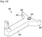
- the trigger 220 includes a trigger bar 222 forming a body and a connecting arm 226 and a stopper 228 branched at one end of the trigger bar 222 and has a substantially T shape.
- the trigger 220 may also include a trigger pivot hole 225 formed at a midpoint between the trigger bar 222 and the connecting arm 226 and the stopper 228.
- the trigger pivot hole 225 is disposed between a pair of trigger supports 118a formed on one side of the housing 110.
- a trigger support hole 118b is formed in each of the pair of trigger supports 118a and the trigger 220 is pivotally mounted on the housing 110 by the pair of trigger support holes 118b and a trigger pivot pin 118d passing through the trigger pivot hole 225.
- An elastic member 118c may be disposed between the trigger 220 and the trigger support 118a so that the trigger 220 is biased in a direction to press the lever 210 or vice versa.
- the clutch assembly 100 may include a lever holder 190 coupled to the lower surface of the housing 110.
- the lever holder 190 includes an annular holder body 196, a housing coupling 192 for coupling the holder body 196 to the housing 110 and a pair of lever supporting portions 198a protruding from one side of the holder body 196.
- the lever holder 190 may be fixed to the lower surface of the housing 110 by a plurality of fastening members (not shown) and may alternatively be formed integrally with the housing 110.
- lever supporting portion holes 198b are formed in the pair of lever supporting portions 198a, respectively and the lever 210 is pivotally mounted on the lever holder 190 by a lever pivot pin 198d passing through a pair of lever supporting portion holes 198b and a lever pivot hole 215.
- An elastic member 198c may be disposed between the lever 210 and the lever holder 190 such that the guide arm 216 of the lever 210 is biased downward.
- the operating modes of the clutch assembly are determined to be the first, second, and third modes depending on the position of the coupling 160 in the upper, middle, and lower positions.
- the coupling 160 may be configured to reciprocate using a cam, a gear, or the like.
- a coupling stopper 191 is disposed adjacent to the hollow portion of the lever holder 190 and includes a plurality of protrusions 191a protruding downward from the lower surface of the holder body 196.
- the coupling stopper 191 has a shape corresponding to the coupling teeth 166 so that the coupling stopper 191 is engaged with the coupling teeth 166 at a position where the coupling 160 is raised.
- the clutch boss 180 may include the boss hole 183 formed in the center portion, the circular hub 182 surrounding the boss hole 183 and the boss teeth 184 formed along the periphery of the hub 182.
- the boss teeth 184 include a plurality of boss protrusions 184 protruding radially from the outer periphery of the hub and a plurality of boss grooves 185 formed in a groove shape between the boss protrusions 184. Accordingly, the boss teeth 184 and the coupling gear 170 are engaged with each other at a position where the coupling 160 is lowered, and the power of the motor is transmitted to the coupling 160 so that the coupling 160 can rotate.
- a first mode M1 is a drum rotation mode in which the driving force of the motor is transmitted to the drum only and the pulsator is not rotated.
- the trigger 220 which receives a force in the direction of an arrow F1 from an actuator (not shown) rotates counterclockwise about the trigger pivot hole 225, the lever contact portion 227 of the trigger 220 presses the upper lever 212, the lever 210 is pivotally rotated about the lever pivot hole 215, and the upper lever 212 of the lever moves away from the housing 110 side and the guide arm 216 of the lower lever 214 lifts the coupling 160.
- the coupling teeth 166 of the coupling 160 are engaged with the coupling stopper 191 of the lever holder 190 to restrain the rotation of the coupling 160 and the pulsator shaft restricting portion 164 of the coupling 160 is engaged with the pulsator shaft teeth 133 to restrain the lower pulsator shaft 132.
- the rotation of the lower pulsator shaft 132 is restrained, the rotation of the planetary gears 152 disposed at the upper portion of the lower pulsator shaft 132 is free to rotate, but the revolution of the planetary gears 152 is restrained. That is, the planetary gear shafts 152a cannot rotate about the sun gear 122.
- the drum shaft teeth 143 of the lower drum shaft 142 are formed between the drum shaft coupling portion 168 of the coupling 160 and the pulsator shaft restricting portion 164 and disposed at flat portions 174 on which no serration is formed and the lower drum shaft 142 is free to rotate without engaging with the coupling 160.
- the power from the driving shaft 120 is transmitted to the ring gear 154 through the rotation of the sun gear 122 and the planetary gears 152.
- This operation causes the drum driving portion 140 connected to the ring gear 154 to rotate.
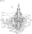
- This power transmission path follows an arrow T1 shown in FIG. 14 . That is, the power of the motor 70 rotates the drum 40 through the clutch boss 180, the driving shaft 120, the planetary gear 152, the ring gear 154, the gearbox 146 and the upper drum shaft 144.
- the rotational direction of the motor 70 and the rotational direction of the drum 40 are opposite to each other, and the rotational speed of the motor 70 versus the rotational speed of the drum 40 is approximately 4: 1 to 5: 1 and the ratio of the rotational speed of the motor 70 to the rotational speed of the drum 40 varies depending on the number of gear teeth of the sun gear 122, the number of gear teeth of the planetary gear 152, and the number of gear teeth of the ring gear 154.
- the washing machine according to the present invention can operate in a first mode during a washing or rinsing cycle and operate in the first mode in some process during the wash cycle or in some process during the rinse cycle.
- the washing machine according to the present invention has an advantage that the damage of the loundry can be reduced by having the process of rotating the rotating drum only while the pulsator is stopped during the washing cycle.
- the rinsing cylce is usually repeated two or more times and at the time of the first rinsing cycle or the last rinsing cycle, the washing machine is programmed to operate in the first mode, thereby saving washing water.
- FIGS. 15 and 16 are diagrams illustrating the operation of the clutch assembly in the second mode according to an embodiment of the present invention.
- the trigger 220 which receives the force in the direction of an arrow F2 from the actuator rotates counterclockwise about the trigger pivot hole 225 as in the first mode M1, and the angle by which the actuator rotates the trigger 220 in the second mode M2 is smaller than in the case of the first mode. That is, when the rotation angle of the trigger 220 is substantially maximum in the first mode M1 and the stopper 228 of the trigger 220 is in contact with the side surface of the housing 110 as shown in FIG. 13 The stopper 228 of the trigger 220 maintains the distance d1 from the housing 110 in the second mode M2.
- the position of the trigger 220 in the second mode M2 is approximately halfway between the position of the trigger 220 in the first mode M1 and the position of the trigger 220 in a third mode M3 described below.
- the actuator may operate only in the first mode M1 and the third mode M3, and the actuator may not operate in the second mode M2.
- the lever 210 pivots about the lever pivot hole 215 as described above and the coupling 160 is raised by the guide arm 216 of the lower lever 214.
- the position of the coupling 160 in the first mode M1 is referred to as an upper position
- the position of the coupling 160 in the second mode M2 may be referred to as a middle position. That is, in the second mode M2, the coupling 160 is lower than the position of the coupling 160 in the first mode M1.
- the pulsator shaft teeth 133 of the lower pulsator shaft 132 are also located above the pulsator shaft restricting portion 164 without engaging the pulsator shaft restricting portion 164 of the coupling 160, and the drum shaft teeth 143 of the lower drum shaft 142 are also located below the drum shaft coupling portion 168 without engaging the drum shaft coupling portion 168 of the coupling 160. That is, the pulsator shaft teeth 133 and the drum shaft teeth 143 are positioned at the flat portion 174 between the pulsator shaft restricting portion 164 of the coupling 160 and the drum shaft coupling portion 168. Consequently, in the second mode M2, the coupling 160 does not engage the lever holder 190, the pulsator shaft teeth 133, or the drum shaft teeth 143.
- the power from the driving shaft 120 is transmitted to the plurality of planetary gears 152 via the sun gear 122.
- the power by the rotation of the planetary gear 152 is transmitted to the ring gear 154.
- the moment of inertia for rotating the drum 40 in the stopped state is much larger than the moment of inertia for rotating the pulsator 45 in the stopped state.
- the rotation of the planetary gears 152 causes the planetary gears 152 themselves to revolve along the ring gear 154, instead of rotating the ring gear 154.
- the revolutions of these planetary gears 152 cause the pulsator drive portion 130 and the pulsator 45 to rotate through the planetary gear connecting portions 135 and 136.
- a braking device (not shown) may be mounted in contact with the side of the gearbox 146 to more reliably restrain the rotation of the drum driving portion 140.
- the brake device may be operated to restrain the drum driving portion 140 in the second mode M2 and to release the constraint of the drum driving portion 140 in the first mode M1 and the third mode M3.
- the power of the motor 70 rotates the pulsator 45 by being transmitted to the pulsator driving portion 130 through the rotation of the sun gear 122 of the driving shaft 120 and revolution of the planetary gears 152.
- the power transmission path at this time follows an arrow T2 shown in FIG. 16 .
- the rotational direction of the motor 70 is the same as the rotational direction of the pulsator 45, but the rotational speed of the pulsator 45 is reduced with respect to the rotational speed of the motor at a rotational speed of 4: 1 to 5: 1.
- the deceleration rate may vary depending on the number of gear teeth of the sun gear 122, the planetary gear 152, or the ring gear 154.
- the washing machine according to the present invention can operate in the second mode during a washing or rinsing cycle and can operate in the second mode for a part of the washing cycle.
- the rotation direction of the drum is opposite to the rotation direction of the motor
- the rotation direction of the pulsator is the same as the rotation direction of the motor. Therefore, when the first mode and the second mode are alternately operated in the washing cycle, the rotating direction of the water flow and laundry is naturally alternated. That is, conventionally, in the washing cycle, the rotation direction of the motor is changed to change the water flow.
- the washing operation can be performed while changing the rotating direction of the water flow through the conversion of the first mode and the second mode without changing the rotating direction of the motor.
- FIGS. 17 and 18 are diagrams illustrating the operation of the clutch assembly in the third mode according to an embodiment of the present invention.
- the actuator does not operate in the third mode M3. That is, the actuator does not exert any force on the trigger 220, the trigger 220 maintains the original state without pivoting, and the stopper 228 of the trigger 220 is spaced apart from the housing 110 by a distance d2 that is greater than the distance d1. Further, since the trigger 220 does not press the upper lever 212, by the elastic force of the elastic member 198c coupled to the lever pivot hole 215, the upper lever 212 is upright so as to be substantially horizontal with the rotation axis X of the motor and the guide arm 216 of the lower lever 214 does not press the coupling 160.
- the coupling 160 can be located at the lowest position by gravity, and the coupling 160 is biased to engage with the clutch boss 180 by the elastic force of the spring 176 disposed between the lever holder 190 and the coupling 160.
- the coupling gear 170 of the coupling 160 is engaged with the boss teeth 184 of the clutch boss 180 and the position of the coupling 160 at this time is referred to as a lower position.
- the drum shaft coupling portion 168 of the coupling 160 engages the drum shaft teeth 143.
- the pulsator shaft teeth 133 are located on the flat portion 174 of the coupling 160, they do not engage with the coupling 160.
- the power of the motor 40 in the third mode M3 is transmitted not only to the driving shaft 120 but also to the coupling 160 coupled with the clutch boss 180. Also, the drum driving portion 140 is rotated by the drum shaft teeth 143 engaged with the drum shaft coupling portion 168 of the coupling 160. Therefore, since the rotational speed of the driving shaft 120 and the rotational speed of the drum driving portion 140 are the same, no power transmission occurs between the sun gear 122 and the planetary gears 152 of the drive shaft 120 and no power transmission occurs between the planetary gears 152 and the ring gear 154. In other words, the pulsator driving portion 130 and the drum driving portion 140 are rotated as one rigid body. In the third mode M3, the power transmission path follows an arrow T3 shown in FIG. 18 , and the rotation speed and rotation direction of the motor 70, the pulsator 45, and the drum 40 are the same.
- the third mode M3 is a mode that operates during the dewatering cycle of the washing machine, which separates the water contained in the laundry by rotating the drum and the pulsator at a high speed.
- the washing machine may be operated in the third mode even during the washing or rinsing cycle.
- the washing machine may operate the drum rotation mode, which is the first mode M1, the pulsator rotation mode, which is the second mode M2, and a dehydration mode, which is the third mode M3.
- the first and third modes M1 and M3 may be operated by moving the trigger 220 and the second mode M2 may be operated by moving the lever 210.
- the trigger 220 and the lever 210 can be operated by first and second actuators A1 and A2, respectively.
- the stopper 228 of the trigger 220 is in contact with the side surface of the housing 110 as shown in FIG. 19 .
- the coupling 160 is moved to the upper position as shown in FIG. 14 , and the coupling 160 is engaged with the coupling stopper 191 and the pulsator shaft teeth 133 so that the power is transmitted from the motor 70 to be transferred to the drum 40.
- the stopper 228 of the trigger 220 is separated from the side surface of the housing 110 by the distance d2 as shown in FIG. 20 .
- the coupling 160 is moved to the lower position as shown in FIG. 18 and the clutch boss 180 and the drum shaft teeth 143 are engaged with each other so that the power is transmitted from the motor 70 to the pulsator 45 and the drum 40.
- the trigger 220 when converting from the first mode M1 to the third mode M3, the trigger 220 may be rotated by the first actuator A1 such that the stopper 228 of the trigger 220 is spaced apart from the housing 110 by the distance d2.
- the trigger 220 when converting from the third mode M3 to the first mode M1, the trigger 220 may be rotated by the first actuator A1 such that the stopper 228 of the trigger 220 closely contacts the housing 110.
- the washing machine can operate the drum rotation mode and the dehydration mode.
- the second mode M2 can be operated by moving the lever 210.
- the lever 210 is provided so as to move independently of the trigger 220 by the second actuator A2 as shown in FIG. 21 . That is, the second mode M2 can be turned on / off by the second actuator A2.
- the second actuator A2 operates the upper lever 212 so that the guide arm 216 of the lower lever 214 moves the coupling 160.
- the coupling 160 in the second mode M2 may be in the middle position as shown in FIG. 16 .
- the coupling 160 is not constrained to the pulsator shaft teeth 133 and the drum shaft teeth 143, so that the power is transferred from the motor 70 to the pulsator 45.
Landscapes
- Engineering & Computer Science (AREA)
- Textile Engineering (AREA)
- General Engineering & Computer Science (AREA)
- Power Engineering (AREA)
- Mechanical Engineering (AREA)
- Main Body Construction Of Washing Machines And Laundry Dryers (AREA)
Description
- The present invention relates to a washing machine, and more particularly, to a washing machine that improves the structure of a clutch assembly that transmits power of a motor.
- A washing machine is a machine for washing clothing using electric power. The washing machine generally includes a tub for storing wash water, a drum rotatably installed in a water tank, a pulsator rotatably installed on the bottom of the drum, a motor for rotationally driving the pulsator, and a clutch assembly for transmitting the power of the motor to the drum and the pulsator.
- In the washing machine, during the washing cycle, the pulsator rotates while laundry and water are contained in the drum, and contaminants are separated from the laundry by a water stream formed in the drum, and during the rinse cycle, the drum and the pulsator rotate together so that the separated contaminants are dissolved in the water.
- Therefore, the conventional washing machine is equipped with a clutch assembly that converts a mode for transmitting the power of the motor to the pulsator to a mode for transmitting the power of the motor to both the pulsator and the drum. For instance,
WO 2004/069020 A2 ,WO 2015/188683 A1 andUS 2012/222454 A1 are all directed to washing machines comprising a pulsator located inside a drum and directly connected to a motor and a clutch for selectively transmitting power to the drum. In other words, the clutch assembly mounted in the conventional washing machine does not have a mechanism for transmitting the power of the motor only to the drum. - However, in the process of washing the drum by rotating only the pulsator while the drum is stopped, the laundry is often twisted. Depending on the type of laundry, it may be effective to rotate only the rotating drum while the pulsator is stopped.
- Therefore, it is an aspect of the present invention to provide a washing machine capable of transmitting the power of a motor to only a drum.
- It is another aspect of the present invention to provide a washing machine capable of alternating the direction of the water flow inside the drum without changing the rotating direction of the motor.
- The drawbacks of the prior art are solved according to the present invention by a washing machine as defined in the
independent claim 1. In accordance with one aspect of the disclosure, a washing machine includes a tub for storing water, a drum rotatably disposed in the tub, a pulsator provided within the drum, the pulsator being rotatable independently of the drum, a motor for generating power and a clutch assembly for transmitting the power of the motor to the drum or the pulsator. The clutch assembly includes a pulsator driving portion coupled to the pulsator to transmit the power of the motor to the pulsator and a coupling selectively coupled to the pulsator driving portion such that the power of the motor is not transmitted to the pulsator. - The clutch assembly may transfer the power of the motor to the drum or the pulsator by raising or lowering the coupling.
- The washing machine further includes a drum driving portion coupled to the drum to transmit the power of the motor to the drum. The driving direction of the drum is opposite to the rotating direction of the motor when the power of the motor is transmitted to the drum driving portion and the power of the motor is not transmitted to the pulsator driving portion.
- The washing machine may further include a sun gear for receiving the power of the motor; and a plurality of planetary gears disposed around the sun gear to engage the sun gear. The pulsator driving portion preferably includes a planetary gear connecting portion connecting a plurality of planetary gear shafts passing through a rotation center of each of the plurality of planetary gears.
- The drum driving portion may include a ring gear surrounding the plurality of planetary gears and engaging the plurality of planetary gears.
- The coupling is preferably adapted to restrain the rotation of the planetary gear connecting portion so that the plurality of planetary gears do not revolve about the sun gear so that the power is not transmitted to the pulsator.
- In accordance with aspect preferred embodiment of the disclosure, the clutch assembly includes a driving shaft receiving the power from the motor, a pulsator shaft surrounding the driving shaft and coupled to the pulsator to transmit the power of the motor to the pulsator, pulsator shaft teeth formed on the outer periphery of the pulsator shaft and a coupling engaged with the pulsator shaft teeth to selectively restrict the rotation of the pulsator shaft.
- The clutch assembly may include a drum shaft surrounding the pulsator shaft and coupled to the drum to transmit the power of the motor to the drum and drum shaft teeth formed on an outer circumference of the drum shaft.
- Preferably, the coupling includes a pulsator restricting portion engaging the pulsator shaft teeth and a drum coupling portion engaging the drum shaft teeth.
- Preferably, the power of the motor is transmitted to the drum via the coupling when the drum coupling portion is engaged with the drum shaft teeth.
- Preferably, the clutch assembly raises or lowers the coupling such that the coupling selectively engages the pulsator shaft teeth.
- Preferably, the washing machine further includes a sun gear formed at one end of the driving shaft, a plurality of planetary gears disposed around the sun gear and engaging the sun gear and a ring gear surrounding the plurality of planetary gears and meshing with the plurality of planetary gears. When the coupling is engaged with the pulsator shaft teeth and the rotation of the pulsator shaft is restricted, the plurality of planetary gears cannot revolve around the sun gear and the ring gear rotates.
- In accordance with a further embodiment of the disclosure, the washing machine further includes a driving shaft including a sun gear for receiving the power from the motor, a plurality of planetary gears disposed around the sun gear and engaging the sun gear and a ring gear surrounding the plurality of planetary gears and configured to engage with the plurality of planetary gears. The pulsator driving portion rotates as the plurality of planetary gears rotate about the sun gear along the ring gear.
- Preferably, the washing machine further comprises a coupling for selectively restricting the rotation of the pulsator driving portion to prevent revolution of the plurality of planetary gears.
- Preferably, the washing machine may further include a drum driving portion coupled to the drum to transmit the power to the drum. The drum driving portion is engaged with the ring gear to rotate integrally.
- Preferably, the coupling selectively restrains the rotation of the pulsator driving portion by raising or lowering the coupling.
- According to an aspect of the invention, the operating mode of the washing machine can be varied by an improved clutch assembly. Particularly, when the washing machine is operated by appropriately combining a pulsator rotation mode, drum rotation mode, and pulsator and drum simultaneous rotation mode during washing or rinsing, there is an advantage in that the washing power is improved and water consumption is reduced.
-
-
FIG. 1 is a cross-sectional view of a washing machine according to an embodiment of the present invention. -
FIG. 2A is a perspective view of a clutch assembly according to an embodiment of the present invention. -
FIG. 2B is a bottom perspective view of a clutch assembly and a rotor according to an embodiment of the present invention. -
FIG. 3 is an exploded perspective view of a clutch assembly according to an embodiment of the present invention. -
FIG. 4 is an exploded perspective view of a drum driving portion and a pulsator driving portion according to an embodiment of the present invention. -
FIG. 5 is an enlarged view of a lower drum shaft and a lower pulsator shaft according to an embodiment of the present invention. -
FIG. 6 is a cross-sectional view of a clutch assembly according to an embodiment of the present invention. -
FIG. 7 is a front view of a planetary gear assembly according to an embodiment of the present invention. -
FIG. 8 is a top perspective view of a coupling according to an embodiment of the present invention. -
FIG. 9 is a bottom perspective view of a coupling according to an embodiment of the present invention. -
FIG. 10 is a cross-sectional view of a coupling according to an embodiment of the present invention. -
FIG. 11 is a perspective view of a lever according to an embodiment of the present invention. -
FIG. 12 is a perspective view of a trigger according to an embodiment of the present invention. -
FIGS. 13 and14 are views of operating positions of a coupling in a first mode of a clutch assembly according to an embodiment of the present invention. -
FIGS. 15 and16 are views of operating positions of a coupling in a second mode of a clutch assembly according to an embodiment of the present invention. -
FIGS. 17 and18 are diagrams illustrating operating positions of a coupling in a third mode of a clutch assembly according to an embodiment of the present invention. -
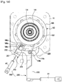
FIGS. 19 and21 are diagrams illustrating the operation of a clutch assembly according to another embodiment of the present invention. - Embodiments described in this specification and configurations illustrated in the drawings are only exemplary examples of the disclosed invention, and the invention covers various modifications that can substitute the embodiments herein and drawings at the time of filing of this application.
- In addition, the same reference number refers to a part or component substantially performing the same function.
- In addition, the terms used in the present specification are merely used to describe embodiments and are not intended to limit and/or restrict embodiments. An expression used in the singular form encompasses the expression in the plural referent unless it has a clearly different meaning in the context. In the present specification, terms such as "including," "having," and "comprising" are intended to indicate the existence of the features, numbers, steps, actions, components, parts, or combinations thereof disclosed in the specification and are not intended to preclude the possibility that one or more other features, numbers, steps, actions, components, parts, or combinations thereof may exist or may be added.
- In addition, although the terms "first," "second," etc. may be used herein to describe various elements, these elements should not be limited by these terms. These terms are only used to distinguish one element from another. For example, a first element could be termed a second element, and, similarly, a second element could be termed a first element without departing from the scope of the present invention. As used herein, the term "and/or" includes any and all combinations of one or more of the associated listed items.
- Hereinafter, embodiments according to the present invention will be described in detail with reference to the accompanying drawings.
-
FIG. 1 is a cross-sectional view of a washing machine according to an embodiment of the present invention. - As shown in
FIG. 1 , awashing machine 1 includes acabinet 20 for forming an outer appearance, atub 30 disposed inside thecabinet 20 for storing wash water, adrum 40 disposed rotatably, and apulsator 45 disposed inside thedrum 40 to generate a water stream. - An
inlet 22 is formed in the upper part of thecabinet 20 to allow laundry to be introduced into thedrum 40. Theinlet 22 is opened and closed by adoor 21 installed on the upper part of thecabinet 20. - The
tub 30 is supported by thecabinet 20 by asuspension device 31 connecting the lower outer side of thetub 30 and the upper side of thecabinet 20. The vibration generated in thetub 30 during washing or dehydrating by thesuspension device 31 is prevented from being transmitted to thecabinet 20. - A
water supply pipe 51 for supplying washing water to thetub 30 is installed at an upper portion of thetub 30. One side of thewater supply pipe 51 is connected to an external water source (not shown), and the other side of thewater supply pipe 51 is connected to adetergent supply pipe 50. Water supplied through thewater supply pipe 51 is supplied to the inside of thetub 30 together with the detergent via thedetergent supply pipe 50. Awater supply valve 52 is installed in thewater supply pipe 51 to control the supply of water. - A plurality of dehydration holes 41 are provided on the side of the
drum 40 to communicate with the inner space of thedrum 40 and the inner space of thetub 30. - A
balancer 42 can be mounted on the upper portion of thedrum 40 so that an unbalanced load generated in thedrum 40 during the high speed rotation of thedrum 40 is offset and thedrum 40 can be stably rotated. - The
pulsator 45 is rotated forward or reverse to generate a water flow, and the laundry in thedrum 40 is stirred together with the washing water by the water flow. - A
drainage hole 60 is formed at the bottom of thetub 30 to discharge the washing water stored in thetub 30 and afirst drain pipe 61 is connected to thedrainage hole 60. Thefirst drain pipe 61 is provided with adrain valve 62 for interrupting drainage. - The outlet of the
drain valve 62 is connected to asecond drain pipe 63 for discharging the wash water to the outside. Thedrain valve 62 may be provided in various configurations such as a solenoid device or a link device connected to an electric motor. - A
motor 70 for generating a driving force by receiving power is disposed at a lower end of thetub 30. Themotor 70 consists of acircular stator 71 and arotor 72 disposed on the outer periphery of thestator 71. Ashaft hole 75 is formed at the center of therotor 72 so that a shaft or aclutch boss 180 engaged with aserration 77 formed on the inner circumferential surface of theshaft hole 75 is rotated. Aclutch assembly 100 is disposed between themotor 70 and thetub 30 to selectively transmit the driving force of themotor 70 to thedrum 40 and thepulsator 45. - Particularly, in this embodiment, a direct coupling structure in which the
motor 70 and theclutch assembly 100 are vertically arranged in a line is shown. -
FIG. 2A is a perspective view of a clutch assembly according to an embodiment of the present invention,FIG. 2B is a bottom perspective view of a clutch assembly and a rotor according to an embodiment of the present invention, andFIG. 3 is a perspective view of a clutch assembly according to an embodiment of the present invention. - The
clutch assembly 100 receives power from themotor 70 and is adapted to selectively transmit a driving force to at least one of thepulsator 45 and thedrum 40. Theclutch assembly 100 includes ahousing 110 that is configured to protect its internal configuration. Thehousing 110 is divided into anupper housing 112 and alower housing 114. A portion of a drivingshaft 120 protrudes below thelower housing 114 and a portion of adrum driving portion 140 and a portion of apulsator drive portion 130 protrude above theupper housing 112. - The
clutch assembly 100 includes the drivingshaft 120, thepulsator drive portion 130, thedrum driving portion 140, and theclutch boss 180. - The
clutch boss 180 may include aboss hole 183 formed in the center portion, acircular hub 182 surrounding theboss hole 183 andboss teeth 184 formed along the periphery of thehub 182. Theclutch boss 180 is a component to which the driving force of themotor 70 is primarily transmitted and aboss gear 187 corresponding to theserration 77 provided on the inner circumferential surface of theshaft hole 75 of therotor 72 is formed on the outer periphery of thehub 182 protruding downward. That is, theclutch boss 180 is always rotated integrally with themotor 70. Theboss hole 183 is formed to have a polygonal cross-section, and functions to transmit power to the drivingshaft 120 coupled to theboss hole 183. The detailed configuration of theclutch boss 180 will be described later. - The driving
shaft 120 is connected to theclutch boss 180 so that the power generated by themotor 70 is transmitted to thepulsator drive portion 130 or thedrum driving portion 140. The drivingshaft 120 is a rod shaft and includes aboss engaging portion 126 at one end for engaging theclutch boss 180 and a serration type gear at the other end that functions as asun gear 122 of aplanetary gear assembly 150. Theboss engaging portion 126 has a polygonal cross-section corresponding to theboss hole 183 and is fitted in theboss hole 183. Thus, the drivingshaft 120 is always rotated integrally with themotor 70. - The
pulsator drive portion 130 may be conveniently divided into alower pulsator shaft 132 and anupper pulsator shaft 134. Thelower pulsator shaft 132 and theupper pulsator shaft 134 do not operate independently but rotate integrally. Thelower pulsator shaft 132 is a cylindrical shaft whose center is hollow and the drivingshaft 120 can be inserted into the hollow portion of thelower pulsator shaft 132.Pulsator shaft teeth 133 may be provided on the lower circumference of thelower pulsator shaft 132. Thepulsator shaft teeth 133 are serration-shaped in such a manner that a plurality of projections are spaced apart along the outer circumferential surface of thelower pulsator shaft 132 and are selectively engaged with a pulsatorshaft restricting portion 164 of acoupling 160 to be described later. - An upper portion of the
lower pulsator shaft 132 is provided with a lower planetarygear connecting portion 136 on which a plurality ofplanetary gears 152 are mounted and the lower planetarygear connecting portion 136 engages with an upper planetarygear connecting portion 135 disposed thereabout with theplanetary gears 152 therebetween. Theupper pulsator shaft 134 is coupled to the center of the upper planetarygear connecting portion 135 and thepulsator 45 is coupled to one end of theupper pulsator shaft 134 to rotate thepulsator 45. - The
drum driving portion 140 can be divided into alower drum shaft 142 and anupper drum shaft 144 for convenience. Thelower drum shaft 142 and theupper drum shaft 144 do not operate independently but rotate integrally. Thelower drum shaft 142 is a cylindrical shaft whose center is hollow and thelower pulsator shaft 132 can be inserted into the hollow portion of thelower drum shaft 142. Accordingly, thelower pulsator shaft 132 surrounds the drivingshaft 120 located at the center, and thelower drum shaft 142 encloses thelower pulsator shaft 132. -
Drum shaft teeth 143 may be provided on the outer periphery of the lower end of thelower drum shaft 142. Thedrum shaft teeth 143 are of a serration type in which a plurality of protrusions are spaced apart along the outer peripheral surface of thelower drum shaft 142. As shown inFIG. 5 , thedrum shaft teeth 143 are located above thepulsator shaft teeth 133. Thedrum shaft teeth 143 can be selectively engaged with a drumshaft coupling portion 168 of thecoupling 160 described below. When thelower drum shaft 142 is engaged with thecoupling 160, the power of the motor is transmitted to thedrum driving portion 140 through thecoupling 160. - A
gearbox base 146b in the form of a flange is provided at the upper end of thelower drum shaft 142 so that the upper surface of thegearbox base 146b faces the lower surface of the lower planetarygear connecting portion 136. A lubricant such as grease is applied between the upper surface of thegearbox base 146b and the lower surface of the lower planetarygear connecting portion 136 to enable the relative rotation of thelower drum shaft 142 with respect to thelower pulsator shaft 132. - The
upper drum shaft 144 includes agearbox 146 that is coupled onto thegearbox base 146b of thelower drum shaft 142. Adrum coupling portion 147 is provided on the side of theupper drum shaft 144 opposite to thegearbox 146 and coupled to thedrum 40 so that the power of themotor 70 is transmitted to thedrum 40. - The
upper drum shaft 144 is a cylindrical shaft whose center is hollow, and theupper pulsator shaft 134 can be inserted into the hollow portion of theupper drum shaft 144. Since theupper drum shaft 144 and theupper pulsator shaft 134 are spaced apart from each other so as not to contact each other, they can rotate independently of each other. Theupper pulsator shaft 134 protrudes higher than thedrum coupling portion 147 of theupper drum shaft 144 and is coupled to thepulsator 45. -
FIG. 7 is a front view of a planetary gear assembly according to an embodiment of the present invention. - Referring to
FIGS. 6 and7 , theplanetary gear assembly 150 is connected to the drivingshaft 120, thedrum driving portion 140, and thepulsator drive portion 130 and the driving force is transmitted from the drivingshaft 120 to the driving portion of at least one of thedrum driving portion 140 and thepulsator drive portion 130. - The
planetary gear assembly 150 is disposed within thegearbox 146 that constitutes part of thedrum driving portion 140. Thegearbox 146 includes acylindrical gearbox body 146a having a larger diameter than theupper drum shaft 144 below theupper drum shaft 144 and agearbox base 146b formed in the form of a flange on thelower drum shaft 142. - The
planetary gear assembly 150 may include thesun gear 122, the plurality ofplanetary gears 152, and aring gear 154. The rotation of thesun gear 122 causes theplanetary gears 152 engaged with thesun gear 122 to rotate or revolve and thering gear 154 is rotated about the same axis as a rotation axis X of thesun gear 122 by the rotation of theplanetary gears 152. Here, the rotation of theplanetary gears 152 means that each planetary gear rotates around each rotation axis (x1, x2, x3, x4) and the rotation of theplanetary gears 152 means that the rotation axes (x1, x2, x3, x4) of each planetary gear rotate around the rotation axis X of the sun gear. The revolution of theplanetary gears 152 involves the rotation of theplanetary gears 152. That is, when the rotation of thering gear 154 is constrained, theplanetary gears 152 are engaged with thering gear 154 to rotate about thesun gear 122 by the rotation of theplanetary gears 152. On the other hand, when the revolution of theplanetary gears 152 is constrained, thering gear 154 is rotated by the rotation of theplanetary gears 152. - The
sun gear 122 may be provided at one end of the drivingshaft 120. That is, the drivingshaft 120 may include thesun gear 122 provided in a serration form on the outer circumferential surface opposite to the side coupled with theclutch boss 180. The driving force of the motor can be transmitted to the plurality ofplanetary gears 152 and thering gear 154 through thesun gear 122 of the drivingshaft 120. - The plurality of
planetary gears 152 may be coupled to thepulsator drive portion 130. In other words, as theplanetary gears 152 revolve about thesun gear 122, the rotational force is transmitted to theupper pulsator shaft 134. - The
pulsator drive portion 130 may include the pair of planetarygear connecting portions planetary gear shafts 152a that are the rotational centers of each of the plurality ofplanetary gears 152. The pair of planetarygear connecting portions planetary gear shafts 152a so that theplanetary gears 152 rotate about the rotation axis X when they revolve. The planetarygear connecting portions gear connecting portion 135 and the lower planetarygear connecting portion 136. - The center of the upper planetary
gear connecting portion 135 is connected to theupper pulsator shaft 134 and the center of the lower planetarygear connecting portion 136 is connected to thelower pulsator shaft 132. In this embodiment, the upper planetarygear connecting portion 135 is formed integrally with theupper pulsator shaft 134, and the lower planetarygear connecting portion 136 is formed integrally with thelower pulsator shaft 132. - The
ring gear 154 may be connected to thedrum driving portion 140. Thering gear 154 surrounds the plurality ofplanetary gears 152 and has the same rotational axis as thesun gear 122. That is, the serration formed inside thering gear 154 is provided to rotate in engagement with the serration formed on the outer periphery of theplanetary gears 152. The outer circumferential surface of thering gear 154 is closely fixed to the inner circumferential surface of thegearbox body 146a so that thering gear 154 and thegearbox body 146a are integrally rotated. The driving force transmitted to thering gear 154 can be transmitted to thedrum driving portion 140 through this configuration. Thering gear 154 and thegearbox body 146a of thedrum driving portion 140 may be integrally formed. -
FIG. 8 is a top perspective view of a coupling according to an embodiment of the present invention,FIG. 9 is a bottom perspective view of a coupling according to an embodiment of the present invention, andFIG. 10 is a sectional view of a coupling according to an embodiment of the present invention. - The
clutch assembly 100 can be rotated in a first, second or third mode by restricting the rotation of thelower pulsator shaft 132 or transmitting power to thelower drum shaft 142 depending on the position of thecoupling 160. - As described above, the driving
shaft 120, thelower drum shaft 142, and thelower pulsator shaft 132 have the same rotation axis X and by changing the position of thecoupling 160 in the direction of the rotation axis X, a rotational force can be transmitted to thelower drum shaft 142 or the rotation of thelower pulsator shaft 132 can be restrained. - The
coupling 160 may include acylindrical coupling body 162 having a hollow portion. The drivingshaft 120, thelower pulsator shaft 132, and thelower drum shaft 142 may pass through the hollow portion of thecoupling body 162. - The
coupling body 162 can be divided into anupper body 162a and alower body 162b. The drumshaft coupling portion 168 is provided on the inner peripheral surface of theupper body 162a and the pulsatorshaft restricting portion 164 and acoupling gear 170 are provided on the inner side of thelower body 162b. As described above, according to the embodiment of the present invention, since thelower drum shaft 142 surrounds the outer periphery of thelower pulsator shaft 132, the diameter of thelower drum shaft 142 is bigger than the diameter of thelower pulsator shaft 132. The inner diameter of the drumshaft coupling portion 168 corresponding to thelower drum shaft 142 should be formed larger than the inner diameter of the pulsatorshaft restricting portion 164 corresponding to thelower pulsator shaft 132. To this end, thelower body 162b is provided with anextension 163 protruding radially inwardly along the inner periphery of the hollow portion of thecoupling body 162 and the pulsatorshaft restricting portion 164 comprises a serration formed along the inner periphery of theextension portion 163. - The
coupling 160 may include couplingteeth 166 formed at an intermediate position between theupper body 162a and thelower body 162b. Thecoupling teeth 166 protrude from the outer periphery of thecoupling body 162 and are disposed to surround thecoupling body 162. Thecoupling teeth 166 include a plurality ofcoupling protrusions 167a protruding radially outward along the outer periphery and a plurality ofcoupling grooves 167b disposed between thecoupling protrusions 167a. - Next, a lever unit for vertically moving the
coupling 160 will be described with reference toFIGS. 3 and11 to 13 . - The
clutch assembly 100 according to the embodiment of the present invention operates alever unit 200 to determine the position of thecoupling 160. Thelever unit 200 includes alever 210 and atrigger 220. - The
lever 210 is composed of anupper lever 212 and alower lever 214 and is bent on the basis of alever pivot hole 215 formed between theupper lever 212 and thelower lever 214. The ends of thelower lever 214 are branched to form a pair of C-shapedguide arms 216 and each of theguide arms 216 may include acoupling supporting portion 217 that abuts thecoupling 160 to support thecoupling 160. Theupper lever 212 is a portion that receives the force from thetrigger 220 in contact with thetrigger 220 and thelever 210 can pivot about thelever pivot hole 215 by the force applied to theupper lever 212. - The
trigger 220 includes atrigger bar 222 forming a body and a connectingarm 226 and astopper 228 branched at one end of thetrigger bar 222 and has a substantially T shape. Thetrigger 220 may also include atrigger pivot hole 225 formed at a midpoint between thetrigger bar 222 and the connectingarm 226 and thestopper 228. Thetrigger pivot hole 225 is disposed between a pair of trigger supports 118a formed on one side of thehousing 110. Atrigger support hole 118b is formed in each of the pair of trigger supports 118a and thetrigger 220 is pivotally mounted on thehousing 110 by the pair of trigger support holes 118b and atrigger pivot pin 118d passing through thetrigger pivot hole 225. Anelastic member 118c may be disposed between thetrigger 220 and thetrigger support 118a so that thetrigger 220 is biased in a direction to press thelever 210 or vice versa. - Referring to
FIG. 3 , theclutch assembly 100 according to the embodiment of the present invention may include alever holder 190 coupled to the lower surface of thehousing 110. Thelever holder 190 includes anannular holder body 196, ahousing coupling 192 for coupling theholder body 196 to thehousing 110 and a pair oflever supporting portions 198a protruding from one side of theholder body 196. Thelever holder 190 may be fixed to the lower surface of thehousing 110 by a plurality of fastening members (not shown) and may alternatively be formed integrally with thehousing 110. Further, the lever supportingportion holes 198b are formed in the pair oflever supporting portions 198a, respectively and thelever 210 is pivotally mounted on thelever holder 190 by alever pivot pin 198d passing through a pair of lever supporting portion holes 198b and alever pivot hole 215. Anelastic member 198c may be disposed between thelever 210 and thelever holder 190 such that theguide arm 216 of thelever 210 is biased downward. - Referring to
FIG. 13 , with such a configuration, when thetrigger 220 is operated by an actuator (not shown), thetrigger 220 is pivotally rotated counterclockwise around thetrigger pivot hole 225 and thelever contact portion 227 of the connectingarm 226 presses theupper lever 212 and thelever 210 pivots about the leverpivotal hole 215 so that theguide arm 212 of thelever 210 is raising thecoupling 160. In the embodiment of the present invention, the operating modes of the clutch assembly are determined to be the first, second, and third modes depending on the position of thecoupling 160 in the upper, middle, and lower positions. - Although the
lever 210 and thetrigger 220 are used as a mechanism for changing the position of thecoupling 160 in this embodiment, thecoupling 160 may be configured to reciprocate using a cam, a gear, or the like. - A
coupling stopper 191 is disposed adjacent to the hollow portion of thelever holder 190 and includes a plurality ofprotrusions 191a protruding downward from the lower surface of theholder body 196. Thecoupling stopper 191 has a shape corresponding to thecoupling teeth 166 so that thecoupling stopper 191 is engaged with thecoupling teeth 166 at a position where thecoupling 160 is raised. - Referring to
FIG. 3 , theclutch boss 180 may include theboss hole 183 formed in the center portion, thecircular hub 182 surrounding theboss hole 183 and theboss teeth 184 formed along the periphery of thehub 182. Theboss teeth 184 include a plurality ofboss protrusions 184 protruding radially from the outer periphery of the hub and a plurality ofboss grooves 185 formed in a groove shape between theboss protrusions 184. Accordingly, theboss teeth 184 and thecoupling gear 170 are engaged with each other at a position where thecoupling 160 is lowered, and the power of the motor is transmitted to thecoupling 160 so that thecoupling 160 can rotate. - Hereinafter, the operation principle of the
clutch assembly 100 according to the embodiment of the present invention will be described. - First, a first mode M1 is a drum rotation mode in which the driving force of the motor is transmitted to the drum only and the pulsator is not rotated.
- Referring to
FIGS. 13 and14 , thetrigger 220 which receives a force in the direction of an arrow F1 from an actuator (not shown) rotates counterclockwise about thetrigger pivot hole 225, thelever contact portion 227 of thetrigger 220 presses theupper lever 212, thelever 210 is pivotally rotated about thelever pivot hole 215, and theupper lever 212 of the lever moves away from thehousing 110 side and theguide arm 216 of thelower lever 214 lifts thecoupling 160. When thecoupling 160 is in the up position, thecoupling teeth 166 of thecoupling 160 are engaged with thecoupling stopper 191 of thelever holder 190 to restrain the rotation of thecoupling 160 and the pulsatorshaft restricting portion 164 of thecoupling 160 is engaged with thepulsator shaft teeth 133 to restrain thelower pulsator shaft 132. When the rotation of thelower pulsator shaft 132 is restrained, the rotation of theplanetary gears 152 disposed at the upper portion of thelower pulsator shaft 132 is free to rotate, but the revolution of theplanetary gears 152 is restrained. That is, theplanetary gear shafts 152a cannot rotate about thesun gear 122. On the other hand, thedrum shaft teeth 143 of thelower drum shaft 142 are formed between the drumshaft coupling portion 168 of thecoupling 160 and the pulsatorshaft restricting portion 164 and disposed atflat portions 174 on which no serration is formed and thelower drum shaft 142 is free to rotate without engaging with thecoupling 160. - Thus, in this state, the power from the driving
shaft 120 is transmitted to thering gear 154 through the rotation of thesun gear 122 and theplanetary gears 152. This operation causes thedrum driving portion 140 connected to thering gear 154 to rotate. This power transmission path follows an arrow T1 shown inFIG. 14 . That is, the power of themotor 70 rotates thedrum 40 through theclutch boss 180, the drivingshaft 120, theplanetary gear 152, thering gear 154, thegearbox 146 and theupper drum shaft 144. At this time, the rotational direction of themotor 70 and the rotational direction of thedrum 40 are opposite to each other, and the rotational speed of themotor 70 versus the rotational speed of thedrum 40 is approximately 4: 1 to 5: 1 and the ratio of the rotational speed of themotor 70 to the rotational speed of thedrum 40 varies depending on the number of gear teeth of thesun gear 122, the number of gear teeth of theplanetary gear 152, and the number of gear teeth of thering gear 154. - The washing machine according to the present invention can operate in a first mode during a washing or rinsing cycle and operate in the first mode in some process during the wash cycle or in some process during the rinse cycle. In the conventional washing machine, during the washing cycle, the pulsator rotated only with the rotating drum stopped, or the rotating drum and pulsator rotated together, however, the washing machine according to the present invention has an advantage that the damage of the loundry can be reduced by having the process of rotating the rotating drum only while the pulsator is stopped during the washing cycle. Further, in the washing, rinsing and dewatering cycles, which are all the cycles of the washing machine, the rinsing cylce is usually repeated two or more times and at the time of the first rinsing cycle or the last rinsing cycle, the washing machine is programmed to operate in the first mode, thereby saving washing water.
- Next, the power transmission path of the motor will be described when the washing machine according to the present invention operates in a pulsator rotation mode of a second mode M2.
-
FIGS. 15 and16 are diagrams illustrating the operation of the clutch assembly in the second mode according to an embodiment of the present invention. - The
trigger 220 which receives the force in the direction of an arrow F2 from the actuator rotates counterclockwise about thetrigger pivot hole 225 as in the first mode M1, and the angle by which the actuator rotates thetrigger 220 in the second mode M2 is smaller than in the case of the first mode. That is, when the rotation angle of thetrigger 220 is substantially maximum in the first mode M1 and thestopper 228 of thetrigger 220 is in contact with the side surface of thehousing 110 as shown inFIG. 13 Thestopper 228 of thetrigger 220 maintains the distance d1 from thehousing 110 in the second mode M2. In other words, the position of thetrigger 220 in the second mode M2 is approximately halfway between the position of thetrigger 220 in the first mode M1 and the position of thetrigger 220 in a third mode M3 described below. However, in some cases, if the second mode M2 is set to a neutral position, the actuator may operate only in the first mode M1 and the third mode M3, and the actuator may not operate in the second mode M2. - When the
upper lever 212 is applied with a force by the rotation of thetrigger 220, thelever 210 pivots about thelever pivot hole 215 as described above and thecoupling 160 is raised by theguide arm 216 of thelower lever 214. When the position of thecoupling 160 in the first mode M1 is referred to as an upper position, the position of thecoupling 160 in the second mode M2 may be referred to as a middle position. That is, in the second mode M2, thecoupling 160 is lower than the position of thecoupling 160 in the first mode M1. When thecoupling teeth 166 of thecoupling 160 are located below thecoupling stopper 191 without engaging thecoupling stopper 191 of thelever holder 190, thepulsator shaft teeth 133 of thelower pulsator shaft 132 are also located above the pulsatorshaft restricting portion 164 without engaging the pulsatorshaft restricting portion 164 of thecoupling 160, and thedrum shaft teeth 143 of thelower drum shaft 142 are also located below the drumshaft coupling portion 168 without engaging the drumshaft coupling portion 168 of thecoupling 160. That is, thepulsator shaft teeth 133 and thedrum shaft teeth 143 are positioned at theflat portion 174 between the pulsatorshaft restricting portion 164 of thecoupling 160 and the drumshaft coupling portion 168. Consequently, in the second mode M2, thecoupling 160 does not engage thelever holder 190, thepulsator shaft teeth 133, or thedrum shaft teeth 143. - In this state, the power from the driving
shaft 120 is transmitted to the plurality ofplanetary gears 152 via thesun gear 122. The power by the rotation of theplanetary gear 152 is transmitted to thering gear 154. However, since thedrum 40 has a relatively larger mass than thepulsator 45, the moment of inertia for rotating thedrum 40 in the stopped state is much larger than the moment of inertia for rotating thepulsator 45 in the stopped state. Thus, the rotation of theplanetary gears 152 causes theplanetary gears 152 themselves to revolve along thering gear 154, instead of rotating thering gear 154. The revolutions of theseplanetary gears 152 cause thepulsator drive portion 130 and thepulsator 45 to rotate through the planetarygear connecting portions - Alternatively, a braking device (not shown) may be mounted in contact with the side of the
gearbox 146 to more reliably restrain the rotation of thedrum driving portion 140. In this case, the brake device may be operated to restrain thedrum driving portion 140 in the second mode M2 and to release the constraint of thedrum driving portion 140 in the first mode M1 and the third mode M3. - In the second mode M2 according to an embodiment of the present invention, the power of the
motor 70 rotates thepulsator 45 by being transmitted to thepulsator driving portion 130 through the rotation of thesun gear 122 of the drivingshaft 120 and revolution of theplanetary gears 152. The power transmission path at this time follows an arrow T2 shown inFIG. 16 . At this time, the rotational direction of themotor 70 is the same as the rotational direction of thepulsator 45, but the rotational speed of thepulsator 45 is reduced with respect to the rotational speed of the motor at a rotational speed of 4: 1 to 5: 1. The deceleration rate may vary depending on the number of gear teeth of thesun gear 122, theplanetary gear 152, or thering gear 154. - The washing machine according to the present invention can operate in the second mode during a washing or rinsing cycle and can operate in the second mode for a part of the washing cycle. As described above, in the first mode, the rotation direction of the drum is opposite to the rotation direction of the motor, and in the second mode, the rotation direction of the pulsator is the same as the rotation direction of the motor. Therefore, when the first mode and the second mode are alternately operated in the washing cycle, the rotating direction of the water flow and laundry is naturally alternated. That is, conventionally, in the washing cycle, the rotation direction of the motor is changed to change the water flow. However, in the washing machine equipped with the
clutch assembly 100 according to the present invention, the washing operation can be performed while changing the rotating direction of the water flow through the conversion of the first mode and the second mode without changing the rotating direction of the motor. -
FIGS. 17 and18 are diagrams illustrating the operation of the clutch assembly in the third mode according to an embodiment of the present invention. - Unlike the first mode M1 and the second mode M2, the actuator does not operate in the third mode M3. That is, the actuator does not exert any force on the
trigger 220, thetrigger 220 maintains the original state without pivoting, and thestopper 228 of thetrigger 220 is spaced apart from thehousing 110 by a distance d2 that is greater than the distance d1. Further, since thetrigger 220 does not press theupper lever 212, by the elastic force of theelastic member 198c coupled to thelever pivot hole 215, theupper lever 212 is upright so as to be substantially horizontal with the rotation axis X of the motor and theguide arm 216 of thelower lever 214 does not press thecoupling 160. - Thus, the
coupling 160 can be located at the lowest position by gravity, and thecoupling 160 is biased to engage with theclutch boss 180 by the elastic force of thespring 176 disposed between thelever holder 190 and thecoupling 160. When thecoupling 160 is at its lowest position, thecoupling gear 170 of thecoupling 160 is engaged with theboss teeth 184 of theclutch boss 180 and the position of thecoupling 160 at this time is referred to as a lower position. When thecoupling 160 is in the down position, the drumshaft coupling portion 168 of thecoupling 160 engages thedrum shaft teeth 143. On the other hand, since thepulsator shaft teeth 133 are located on theflat portion 174 of thecoupling 160, they do not engage with thecoupling 160. The power of themotor 40 in the third mode M3 is transmitted not only to the drivingshaft 120 but also to thecoupling 160 coupled with theclutch boss 180. Also, thedrum driving portion 140 is rotated by thedrum shaft teeth 143 engaged with the drumshaft coupling portion 168 of thecoupling 160. Therefore, since the rotational speed of the drivingshaft 120 and the rotational speed of thedrum driving portion 140 are the same, no power transmission occurs between thesun gear 122 and theplanetary gears 152 of thedrive shaft 120 and no power transmission occurs between theplanetary gears 152 and thering gear 154. In other words, thepulsator driving portion 130 and thedrum driving portion 140 are rotated as one rigid body. In the third mode M3, the power transmission path follows an arrow T3 shown inFIG. 18 , and the rotation speed and rotation direction of themotor 70, thepulsator 45, and thedrum 40 are the same. - Basically, the third mode M3 is a mode that operates during the dewatering cycle of the washing machine, which separates the water contained in the laundry by rotating the drum and the pulsator at a high speed. However, in some cases, the washing machine may be operated in the third mode even during the washing or rinsing cycle.
- Hereinafter, a washing machine according to another embodiment of the present invention will be described. The description of the constitution overlapping with the above description will be omitted.
- Will be described with reference to the
FIGS. 19 and20 and the drawings described above. - The washing machine may operate the drum rotation mode, which is the first mode M1, the pulsator rotation mode, which is the second mode M2, and a dehydration mode, which is the third mode M3.
- The first and third modes M1 and M3 may be operated by moving the
trigger 220 and the second mode M2 may be operated by moving thelever 210. Referring toFIGS. 19 and20 , thetrigger 220 and thelever 210 can be operated by first and second actuators A1 and A2, respectively. - In the first mode M1, the
stopper 228 of thetrigger 220 is in contact with the side surface of thehousing 110 as shown inFIG. 19 . At this time, thecoupling 160 is moved to the upper position as shown inFIG. 14 , and thecoupling 160 is engaged with thecoupling stopper 191 and thepulsator shaft teeth 133 so that the power is transmitted from themotor 70 to be transferred to thedrum 40. - In the third mode M3, the
stopper 228 of thetrigger 220 is separated from the side surface of thehousing 110 by the distance d2 as shown inFIG. 20 . Thecoupling 160 is moved to the lower position as shown inFIG. 18 and theclutch boss 180 and thedrum shaft teeth 143 are engaged with each other so that the power is transmitted from themotor 70 to thepulsator 45 and thedrum 40. - Since the first mode M1 is the default setting state, when converting from the first mode M1 to the third mode M3, the
trigger 220 may be rotated by the first actuator A1 such that thestopper 228 of thetrigger 220 is spaced apart from thehousing 110 by the distance d2. - On the contrary, if the third mode M3 is the default setting, when converting from the third mode M3 to the first mode M1, the
trigger 220 may be rotated by the first actuator A1 such that thestopper 228 of thetrigger 220 closely contacts thehousing 110. - That is, by the movement of the
trigger 220, the washing machine can operate the drum rotation mode and the dehydration mode. - The second mode M2 can be operated by moving the
lever 210. - The
lever 210 is provided so as to move independently of thetrigger 220 by the second actuator A2 as shown inFIG. 21 . That is, the second mode M2 can be turned on / off by the second actuator A2. - For example, the second actuator A2 operates the
upper lever 212 so that theguide arm 216 of thelower lever 214 moves thecoupling 160. Thecoupling 160 in the second mode M2 may be in the middle position as shown inFIG. 16 . At this time, thecoupling 160 is not constrained to thepulsator shaft teeth 133 and thedrum shaft teeth 143, so that the power is transferred from themotor 70 to thepulsator 45. - By moving the
trigger 220 and thelever 210 through the operation of the first and second actuators A1 and A2 as described above, it is possible to clearly distinguish between the modes, thereby preventing malfunction between the modes. Although a few embodiments of the present invention have been shown and described, it would be appreciated by those skilled in the art that changes may be made in these embodiments without departing from the principles of the invention, the scope of which is defined in the claims.
Claims (15)
- A washing machine (1) comprising:a tub (30) for storing water;a drum (40) rotatably disposed in the tub (30);a pulsator (45) provided within the drum (40), the pulsator (45) being rotatable independently of the drum (40);a motor (70) for generating power; anda clutch assembly (100) for transmitting the power of the motor (70) to the drum (40) or the pulsator (45),characterized in thatthe clutch assembly (100) includes:a pulsator driving portion (130) coupled to the pulsator (45) to transmit the power of the motor (70) to the pulsator (45);a drum driving portion (140) coupled to the drum (40) to transmit the power of the motor (70) to the drum (40); anda coupling (160) selectively coupled to the pulsator driving portion (130) such that the power of the motor (70) is not transmitted to the pulsator (45),wherein the rotating direction of the drum (40) is opposite to the rotating direction of the motor (70) when the power of the motor (70) is transmitted to the drum driving portion (140) and the power of the motor (70) is not transmitted to the pulsator driving portion (130).
- The washing machine according to claim 1, wherein the clutch assembly (100) is configured to transfer the power of the motor (70) to the drum (40) or the pulsator (45) by raising or lowering the coupling (160).
- The washing machine according to claim 1, wherein the washing machine (1) further includes:a driving shaft (120) including a sun gear (122) formed at one end of the driving shaft for receiving the power of the motor (70); anda plurality of planetary gears (152) disposed around the sun gear (122) to be engaged with the sun gear (122), andwherein the pulsator driving portion (130) includes a planetary gear connecting portion (135, 136) connecting a plurality of planetary gear shafts (152a) passing through rotation centers of the plurality of planetary gears (152), respectively.
- The washing machine according to claim 3, wherein the drum driving portion (140) includes a ring gear (154) surrounding the plurality of planetary gears (152) and engaged with the plurality of planetary gears (152).
- The washing machine according to claim 3, wherein the coupling (160) restrains the rotation of the planetary gear connecting portion (135, 136) to prevent the plurality of planetary gears (152) from revolving about the sun gear (122) so that the power is not transmitted to the pulsator (45).
- The washing machine according to claim 1,
wherein the clutch assembly (100) includes:a driving shaft (120) receiving the power from the motor (70);a pulsator shaft (132, 134) surrounding the driving shaft (120) and coupled to the pulsator (45) to transmit the power of the motor (70) to the pulsator (45);pulsator shaft teeth (133) formed on the outer periphery of the pulsator shaft (132, 134); andwherein the coupling (160) is engaged with the pulsator shaft teeth (133) to selectively restrict the rotation of the pulsator shaft (132, 134). - The washing machine according to claim 6, wherein the clutch assembly (100) includes:a drum shaft (142, 144) surrounding the pulsator shaft (132, 134) and coupled to the drum (40) to transmit the power of the motor (70) to the drum (40); anddrum shaft teeth (143) formed on an outer circumference of the drum shaft (142, 144).
- The washing machine according to claim 7, wherein the coupling (160) includes a pulsator restricting portion (165) engaged with the pulsator shaft teeth (133) and a drum coupling portion (147) engaged with the drum shaft teeth (143).
- The washing machine according to claim 8, wherein the power of the motor (70) is transmitted to the drum (40) via the coupling (160) when the drum coupling portion (147) is engaged with the drum shaft teeth (143).
- The washing machine according to claim 6, wherein the clutch assembly (100) is configured to raise or lower the coupling (160) such that the coupling (160) is selectively engaged with the pulsator shaft teeth (133).
- The washing machine according to claim 6, wherein the washing machine further includes:a sun gear (122) formed at one end of the driving shaft (120);a plurality of planetary gears (152) disposed around the sun gear (122) and engaged with the sun gear (122); anda ring gear (154) surrounding the plurality of planetary gears (152) and engaged with the plurality of planetary gears (152),wherein when the coupling (160) is engaged with the pulsator shaft teeth (133) and the rotation of the pulsator shaft (132, 134) is restricted, the plurality of planetary gears (152) is prevented from revolving around the sun gear (122) and the ring gear (154) rotates.
- The washing machine according to claim 1, further comprising:a driving shaft (120) including a sun gear (122) for receiving the power from the motor (70);a plurality of planetary gears (152) disposed around the sun gear (122) and engaged with the sun gear (122); anda ring gear (154) surrounding the plurality of planetary gears (152) and engaged with the plurality of planetary gears (152),wherein the pulsator driving portion (130) rotates as the plurality of planetary gears (152) rotate about the sun gear (122) along the ring gear (154).
- The washing machine according to claim 12, wherein the coupling (160) is further adapted for selectively restricting the rotation of the pulsator driving portion (130) to prevent revolution of the plurality of planetary gears (152).
- The washing machine according to claim 13, wherein the drum driving portion (140) is engaged with the ring gear (154) to rotate integrally.
- The washing machine according to claim 13, wherein the clutch assembly (100) is adapted to selectively restrain the rotation of the pulsator driving portion (130) by raising or lowering the coupling (160).
Applications Claiming Priority (3)
| Application Number | Priority Date | Filing Date | Title |
|---|---|---|---|
| KR20160001475 | 2016-01-06 | ||
| KR1020160110322A KR102629966B1 (en) | 2016-01-06 | 2016-08-29 | Clutch assembly for washing machine |
| PCT/KR2017/000213 WO2017119774A1 (en) | 2016-01-06 | 2017-01-06 | Clutch assembly of washing machine |
Publications (3)
| Publication Number | Publication Date |
|---|---|
| EP3378984A1 EP3378984A1 (en) | 2018-09-26 |
| EP3378984A4 EP3378984A4 (en) | 2018-12-05 |
| EP3378984B1 true EP3378984B1 (en) | 2019-12-11 |
Family
ID=59358487
Family Applications (1)
| Application Number | Title | Priority Date | Filing Date |
|---|---|---|---|
| EP17736146.6A Active EP3378984B1 (en) | 2016-01-06 | 2017-01-06 | Clutch assembly of washing machine |
Country Status (5)
| Country | Link |
|---|---|
| US (1) | US11015279B2 (en) |
| EP (1) | EP3378984B1 (en) |
| KR (1) | KR102629966B1 (en) |
| CN (1) | CN108474167B (en) |
| ES (1) | ES2775063T3 (en) |
Families Citing this family (17)
| Publication number | Priority date | Publication date | Assignee | Title |
|---|---|---|---|---|
| US10968558B2 (en) | 2018-02-14 | 2021-04-06 | Fisher & Paykel Appliances Limited | Integrated motor and gearbox drive system for a washing machine |
| WO2019227656A1 (en) * | 2018-05-29 | 2019-12-05 | 无锡小天鹅电器有限公司 | Brake used for drum clothes washing machine, and drum clothes washing machine |
| CN108866947B (en) * | 2018-05-29 | 2023-08-22 | 无锡小天鹅电器有限公司 | Brake for drum washing machine and drum washing machine |
| EP3739104A4 (en) | 2018-05-29 | 2020-12-16 | Wuxi Little Swan Electric Co., Ltd. | Drum washing machine |
| CN108755017B (en) * | 2018-08-23 | 2024-05-28 | 奇精机械股份有限公司 | Three-power variable frequency clutch |
| KR102821259B1 (en) * | 2019-11-06 | 2025-06-13 | 엘지전자 주식회사 | Washing machine |
| KR102289758B1 (en) * | 2019-12-19 | 2021-08-17 | 엘지전자 주식회사 | Drive apparatus for washing machine |
| CN111218791A (en) * | 2020-02-12 | 2020-06-02 | 北京中轻生产力促进中心 | A stirring reference washing machine with drum washing function |
| KR102737007B1 (en) * | 2020-09-04 | 2024-12-02 | 엘지전자 주식회사 | Laundary treating apparatus |
| CN112176631B (en) * | 2020-09-22 | 2023-04-25 | 海信冰箱有限公司 | Wave washing machine |
| KR102480297B1 (en) * | 2020-12-24 | 2022-12-23 | 엘지전자 주식회사 | A laundry treating apparatus |
| KR20220109809A (en) * | 2021-01-29 | 2022-08-05 | 엘지전자 주식회사 | A laundry treating apparatus |
| KR102503953B1 (en) | 2021-01-29 | 2023-02-27 | 엘지전자 주식회사 | A laundry treating apparatus |
| CN113080733B (en) * | 2021-05-26 | 2025-04-04 | 中山市欧博尔电器有限公司 | Mixer |
| KR102827257B1 (en) * | 2022-10-21 | 2025-07-01 | 엘지전자 주식회사 | Drive system of a washing machine and a washing machine with the same |
| KR102815288B1 (en) * | 2023-03-29 | 2025-06-02 | 엘지전자 주식회사 | Drive system of a washing machine |
| KR20250165088A (en) * | 2024-05-17 | 2025-11-25 | 엘지전자 주식회사 | Drum rotating device and laundry treating apparatus including the same |
Family Cites Families (14)
| Publication number | Priority date | Publication date | Assignee | Title |
|---|---|---|---|---|
| KR100268263B1 (en) * | 1998-01-31 | 2000-10-16 | 윤종용 | Motor-clutch assembly of directly connected type washing machine |
| KR100339520B1 (en) | 1998-07-27 | 2002-10-25 | 삼성전자 주식회사 | Power train of washing machine |
| AU777010B2 (en) * | 2002-01-17 | 2004-09-30 | Lg Electronics Inc. | Direct-drive washing machine |
| JP2006517125A (en) * | 2003-02-06 | 2006-07-20 | エルジー エレクトロニクス インコーポレーテッド | Washing machine |
| KR100615569B1 (en) | 2003-02-06 | 2006-08-25 | 엘지전자 주식회사 | Fully automatic washing machine and its driving device |
| DE602004031407D1 (en) * | 2003-02-06 | 2011-03-31 | Lg Electronics Inc | WASHING MACHINE |
| KR101354216B1 (en) | 2011-03-04 | 2014-01-22 | 삼성전자주식회사 | washer |
| KR101907163B1 (en) * | 2012-02-03 | 2018-12-05 | 삼성전자주식회사 | Clutch assembly and washing machine having the same |
| US9708747B2 (en) | 2012-09-13 | 2017-07-18 | Haier Us Appliance Solutions, Inc. | Assembly and method for shifting between modes of operation for a washing machine appliance |
| KR101524919B1 (en) * | 2013-04-30 | 2015-06-01 | 뉴모텍(주) | Driving apparatus for washing machine |
| CN105358755B (en) * | 2013-07-12 | 2019-06-04 | 阿莫泰克有限公司 | Washing machine driving device, washing machine having the same, and control method of washing machine |
| KR101577869B1 (en) | 2013-11-14 | 2015-12-15 | 동부대우전자 주식회사 | Link lever having assisting function for clutch assembly action |
| KR101603210B1 (en) | 2013-12-26 | 2016-03-25 | 동부대우전자 주식회사 | Apparatus for power transmission and power control of washing machine |
| JP6444622B2 (en) * | 2014-06-12 | 2018-12-26 | アクア株式会社 | Drum washing machine |
-
2016
- 2016-08-29 KR KR1020160110322A patent/KR102629966B1/en active Active
-
2017
- 2017-01-06 US US16/068,164 patent/US11015279B2/en not_active Expired - Fee Related
- 2017-01-06 CN CN201780007501.4A patent/CN108474167B/en not_active Expired - Fee Related
- 2017-01-06 EP EP17736146.6A patent/EP3378984B1/en active Active
- 2017-01-06 ES ES17736146T patent/ES2775063T3/en active Active
Non-Patent Citations (1)
| Title |
|---|
| None * |
Also Published As
| Publication number | Publication date |
|---|---|
| EP3378984A4 (en) | 2018-12-05 |
| KR20170082437A (en) | 2017-07-14 |
| CN108474167B (en) | 2021-06-29 |
| EP3378984A1 (en) | 2018-09-26 |
| ES2775063T3 (en) | 2020-07-23 |
| KR102629966B1 (en) | 2024-01-30 |
| CN108474167A (en) | 2018-08-31 |
| US20190017211A1 (en) | 2019-01-17 |
| US11015279B2 (en) | 2021-05-25 |
Similar Documents
| Publication | Publication Date | Title |
|---|---|---|
| US11015279B2 (en) | Clutch assembly of washing machine | |
| CN102953261B (en) | Water supply installation and the washing machine with this water supply installation | |
| KR100504867B1 (en) | Drum type washing machine with induction motor | |
| JP6282492B2 (en) | Drum washing machine | |
| EP2889417B1 (en) | Power transmission apparatus and power control apparatus for a washing machine | |
| MXPA06006115A (en) | Multiple directional clutch for washing machine. | |
| KR101934655B1 (en) | Drum washing machine | |
| KR100463545B1 (en) | Drum Washer | |
| US20050081573A1 (en) | Washing machine | |
| CN108291352B (en) | washing machine drive | |
| JP2695129B2 (en) | Washing machine power transmission device | |
| CN106574415B (en) | drum washing machine | |
| KR100391350B1 (en) | A washing machine with power conversion apparatus | |
| US11624425B2 (en) | Laundry treatment apparatus | |
| KR102596993B1 (en) | Washing machine | |
| KR100459140B1 (en) | Washer | |
| KR100595560B1 (en) | Direct type washing machine | |
| KR101638542B1 (en) | Washing machine | |
| KR20040104978A (en) | clutch of full automation-type washing machine | |
| KR100595563B1 (en) | Direct type washing machine | |
| KR0132996Y1 (en) | Drive of washing machine | |
| KR100585698B1 (en) | Direct type washing machine | |
| KR20050060679A (en) | Rotor bushing in full automation-type washing machine | |
| KR20000001804U (en) | Clutch device of washing machine | |
| KR20170076622A (en) | Driving Apparatus for Washing Machine Using Unified Shaft |
Legal Events
| Date | Code | Title | Description |
|---|---|---|---|
| STAA | Information on the status of an ep patent application or granted ep patent |
Free format text: STATUS: THE INTERNATIONAL PUBLICATION HAS BEEN MADE |
|
| PUAI | Public reference made under article 153(3) epc to a published international application that has entered the european phase |
Free format text: ORIGINAL CODE: 0009012 |
|
| STAA | Information on the status of an ep patent application or granted ep patent |
Free format text: STATUS: REQUEST FOR EXAMINATION WAS MADE |
|
| 17P | Request for examination filed |
Effective date: 20180622 |
|
| AK | Designated contracting states |
Kind code of ref document: A1 Designated state(s): AL AT BE BG CH CY CZ DE DK EE ES FI FR GB GR HR HU IE IS IT LI LT LU LV MC MK MT NL NO PL PT RO RS SE SI SK SM TR |
|
| AX | Request for extension of the european patent |
Extension state: BA ME |
|
| A4 | Supplementary search report drawn up and despatched |
Effective date: 20181106 |
|
| RIC1 | Information provided on ipc code assigned before grant |
Ipc: D06F 37/12 20060101ALI20181030BHEP Ipc: D06F 37/24 20060101ALI20181030BHEP Ipc: D06F 75/14 20060101ALI20181030BHEP Ipc: D06F 37/30 20060101ALI20181030BHEP Ipc: D06F 37/40 20060101AFI20181030BHEP |
|
| DAV | Request for validation of the european patent (deleted) | ||
| DAX | Request for extension of the european patent (deleted) | ||
| GRAP | Despatch of communication of intention to grant a patent |
Free format text: ORIGINAL CODE: EPIDOSNIGR1 |
|
| STAA | Information on the status of an ep patent application or granted ep patent |
Free format text: STATUS: GRANT OF PATENT IS INTENDED |
|
| INTG | Intention to grant announced |
Effective date: 20190626 |
|
| GRAJ | Information related to disapproval of communication of intention to grant by the applicant or resumption of examination proceedings by the epo deleted |
Free format text: ORIGINAL CODE: EPIDOSDIGR1 |
|
| STAA | Information on the status of an ep patent application or granted ep patent |
Free format text: STATUS: REQUEST FOR EXAMINATION WAS MADE |
|
| GRAR | Information related to intention to grant a patent recorded |
Free format text: ORIGINAL CODE: EPIDOSNIGR71 |
|
| GRAS | Grant fee paid |
Free format text: ORIGINAL CODE: EPIDOSNIGR3 |
|
| STAA | Information on the status of an ep patent application or granted ep patent |
Free format text: STATUS: GRANT OF PATENT IS INTENDED |
|
| GRAA | (expected) grant |
Free format text: ORIGINAL CODE: 0009210 |
|
| STAA | Information on the status of an ep patent application or granted ep patent |
Free format text: STATUS: THE PATENT HAS BEEN GRANTED |
|
| INTC | Intention to grant announced (deleted) | ||
| AK | Designated contracting states |
Kind code of ref document: B1 Designated state(s): AL AT BE BG CH CY CZ DE DK EE ES FI FR GB GR HR HU IE IS IT LI LT LU LV MC MK MT NL NO PL PT RO RS SE SI SK SM TR |
|
| INTG | Intention to grant announced |
Effective date: 20191105 |
|
| REG | Reference to a national code |
Ref country code: GB Ref legal event code: FG4D |
|
| REG | Reference to a national code |
Ref country code: CH Ref legal event code: EP |
|
| REG | Reference to a national code |
Ref country code: AT Ref legal event code: REF Ref document number: 1212285 Country of ref document: AT Kind code of ref document: T Effective date: 20191215 |
|
| REG | Reference to a national code |
Ref country code: DE Ref legal event code: R096 Ref document number: 602017009666 Country of ref document: DE |
|
| REG | Reference to a national code |
Ref country code: IE Ref legal event code: FG4D |
|
| REG | Reference to a national code |
Ref country code: NL Ref legal event code: MP Effective date: 20191211 |
|
| REG | Reference to a national code |
Ref country code: LT Ref legal event code: MG4D |
|
| PG25 | Lapsed in a contracting state [announced via postgrant information from national office to epo] |
Ref country code: LT Free format text: LAPSE BECAUSE OF FAILURE TO SUBMIT A TRANSLATION OF THE DESCRIPTION OR TO PAY THE FEE WITHIN THE PRESCRIBED TIME-LIMIT Effective date: 20191211 Ref country code: NO Free format text: LAPSE BECAUSE OF FAILURE TO SUBMIT A TRANSLATION OF THE DESCRIPTION OR TO PAY THE FEE WITHIN THE PRESCRIBED TIME-LIMIT Effective date: 20200311 Ref country code: GR Free format text: LAPSE BECAUSE OF FAILURE TO SUBMIT A TRANSLATION OF THE DESCRIPTION OR TO PAY THE FEE WITHIN THE PRESCRIBED TIME-LIMIT Effective date: 20200312 Ref country code: FI Free format text: LAPSE BECAUSE OF FAILURE TO SUBMIT A TRANSLATION OF THE DESCRIPTION OR TO PAY THE FEE WITHIN THE PRESCRIBED TIME-LIMIT Effective date: 20191211 Ref country code: BG Free format text: LAPSE BECAUSE OF FAILURE TO SUBMIT A TRANSLATION OF THE DESCRIPTION OR TO PAY THE FEE WITHIN THE PRESCRIBED TIME-LIMIT Effective date: 20200311 Ref country code: LV Free format text: LAPSE BECAUSE OF FAILURE TO SUBMIT A TRANSLATION OF THE DESCRIPTION OR TO PAY THE FEE WITHIN THE PRESCRIBED TIME-LIMIT Effective date: 20191211 Ref country code: SE Free format text: LAPSE BECAUSE OF FAILURE TO SUBMIT A TRANSLATION OF THE DESCRIPTION OR TO PAY THE FEE WITHIN THE PRESCRIBED TIME-LIMIT Effective date: 20191211 |
|
| PGFP | Annual fee paid to national office [announced via postgrant information from national office to epo] |
Ref country code: IT Payment date: 20200131 Year of fee payment: 4 Ref country code: ES Payment date: 20200218 Year of fee payment: 4 |
|
| PG25 | Lapsed in a contracting state [announced via postgrant information from national office to epo] |
Ref country code: RS Free format text: LAPSE BECAUSE OF FAILURE TO SUBMIT A TRANSLATION OF THE DESCRIPTION OR TO PAY THE FEE WITHIN THE PRESCRIBED TIME-LIMIT Effective date: 20191211 Ref country code: HR Free format text: LAPSE BECAUSE OF FAILURE TO SUBMIT A TRANSLATION OF THE DESCRIPTION OR TO PAY THE FEE WITHIN THE PRESCRIBED TIME-LIMIT Effective date: 20191211 |
|
| PG25 | Lapsed in a contracting state [announced via postgrant information from national office to epo] |
Ref country code: AL Free format text: LAPSE BECAUSE OF FAILURE TO SUBMIT A TRANSLATION OF THE DESCRIPTION OR TO PAY THE FEE WITHIN THE PRESCRIBED TIME-LIMIT Effective date: 20191211 |
|
| REG | Reference to a national code |
Ref country code: ES Ref legal event code: FG2A Ref document number: 2775063 Country of ref document: ES Kind code of ref document: T3 Effective date: 20200723 |
|
| PG25 | Lapsed in a contracting state [announced via postgrant information from national office to epo] |
Ref country code: PT Free format text: LAPSE BECAUSE OF FAILURE TO SUBMIT A TRANSLATION OF THE DESCRIPTION OR TO PAY THE FEE WITHIN THE PRESCRIBED TIME-LIMIT Effective date: 20200506 Ref country code: EE Free format text: LAPSE BECAUSE OF FAILURE TO SUBMIT A TRANSLATION OF THE DESCRIPTION OR TO PAY THE FEE WITHIN THE PRESCRIBED TIME-LIMIT Effective date: 20191211 Ref country code: NL Free format text: LAPSE BECAUSE OF FAILURE TO SUBMIT A TRANSLATION OF THE DESCRIPTION OR TO PAY THE FEE WITHIN THE PRESCRIBED TIME-LIMIT Effective date: 20191211 Ref country code: RO Free format text: LAPSE BECAUSE OF FAILURE TO SUBMIT A TRANSLATION OF THE DESCRIPTION OR TO PAY THE FEE WITHIN THE PRESCRIBED TIME-LIMIT Effective date: 20191211 Ref country code: CZ Free format text: LAPSE BECAUSE OF FAILURE TO SUBMIT A TRANSLATION OF THE DESCRIPTION OR TO PAY THE FEE WITHIN THE PRESCRIBED TIME-LIMIT Effective date: 20191211 |
|
| REG | Reference to a national code |
Ref country code: DE Ref legal event code: R119 Ref document number: 602017009666 Country of ref document: DE |
|
| PG25 | Lapsed in a contracting state [announced via postgrant information from national office to epo] |
Ref country code: SM Free format text: LAPSE BECAUSE OF FAILURE TO SUBMIT A TRANSLATION OF THE DESCRIPTION OR TO PAY THE FEE WITHIN THE PRESCRIBED TIME-LIMIT Effective date: 20191211 Ref country code: SK Free format text: LAPSE BECAUSE OF FAILURE TO SUBMIT A TRANSLATION OF THE DESCRIPTION OR TO PAY THE FEE WITHIN THE PRESCRIBED TIME-LIMIT Effective date: 20191211 Ref country code: IS Free format text: LAPSE BECAUSE OF FAILURE TO SUBMIT A TRANSLATION OF THE DESCRIPTION OR TO PAY THE FEE WITHIN THE PRESCRIBED TIME-LIMIT Effective date: 20200411 |
|
| REG | Reference to a national code |
Ref country code: CH Ref legal event code: PL |
|
| PG25 | Lapsed in a contracting state [announced via postgrant information from national office to epo] |
Ref country code: MC Free format text: LAPSE BECAUSE OF FAILURE TO SUBMIT A TRANSLATION OF THE DESCRIPTION OR TO PAY THE FEE WITHIN THE PRESCRIBED TIME-LIMIT Effective date: 20191211 |
|
| REG | Reference to a national code |
Ref country code: BE Ref legal event code: MM Effective date: 20200131 Ref country code: AT Ref legal event code: MK05 Ref document number: 1212285 Country of ref document: AT Kind code of ref document: T Effective date: 20191211 |
|
| PLBE | No opposition filed within time limit |
Free format text: ORIGINAL CODE: 0009261 |
|
| STAA | Information on the status of an ep patent application or granted ep patent |
Free format text: STATUS: NO OPPOSITION FILED WITHIN TIME LIMIT |
|
| PG25 | Lapsed in a contracting state [announced via postgrant information from national office to epo] |
Ref country code: LU Free format text: LAPSE BECAUSE OF NON-PAYMENT OF DUE FEES Effective date: 20200106 Ref country code: DE Free format text: LAPSE BECAUSE OF NON-PAYMENT OF DUE FEES Effective date: 20200801 Ref country code: DK Free format text: LAPSE BECAUSE OF FAILURE TO SUBMIT A TRANSLATION OF THE DESCRIPTION OR TO PAY THE FEE WITHIN THE PRESCRIBED TIME-LIMIT Effective date: 20191211 |
|
| 26N | No opposition filed |
Effective date: 20200914 |
|
| PG25 | Lapsed in a contracting state [announced via postgrant information from national office to epo] |
Ref country code: BE Free format text: LAPSE BECAUSE OF NON-PAYMENT OF DUE FEES Effective date: 20200131 Ref country code: LI Free format text: LAPSE BECAUSE OF NON-PAYMENT OF DUE FEES Effective date: 20200131 Ref country code: CH Free format text: LAPSE BECAUSE OF NON-PAYMENT OF DUE FEES Effective date: 20200131 Ref country code: AT Free format text: LAPSE BECAUSE OF FAILURE TO SUBMIT A TRANSLATION OF THE DESCRIPTION OR TO PAY THE FEE WITHIN THE PRESCRIBED TIME-LIMIT Effective date: 20191211 Ref country code: SI Free format text: LAPSE BECAUSE OF FAILURE TO SUBMIT A TRANSLATION OF THE DESCRIPTION OR TO PAY THE FEE WITHIN THE PRESCRIBED TIME-LIMIT Effective date: 20191211 |
|
| PG25 | Lapsed in a contracting state [announced via postgrant information from national office to epo] |
Ref country code: IE Free format text: LAPSE BECAUSE OF NON-PAYMENT OF DUE FEES Effective date: 20200106 Ref country code: FR Free format text: LAPSE BECAUSE OF NON-PAYMENT OF DUE FEES Effective date: 20200211 |
|
| PG25 | Lapsed in a contracting state [announced via postgrant information from national office to epo] |
Ref country code: PL Free format text: LAPSE BECAUSE OF FAILURE TO SUBMIT A TRANSLATION OF THE DESCRIPTION OR TO PAY THE FEE WITHIN THE PRESCRIBED TIME-LIMIT Effective date: 20191211 |
|
| GBPC | Gb: european patent ceased through non-payment of renewal fee |
Effective date: 20210106 |
|
| PG25 | Lapsed in a contracting state [announced via postgrant information from national office to epo] |
Ref country code: GB Free format text: LAPSE BECAUSE OF NON-PAYMENT OF DUE FEES Effective date: 20210106 |
|
| REG | Reference to a national code |
Ref country code: ES Ref legal event code: FD2A Effective date: 20220413 |
|
| PG25 | Lapsed in a contracting state [announced via postgrant information from national office to epo] |
Ref country code: IT Free format text: LAPSE BECAUSE OF NON-PAYMENT OF DUE FEES Effective date: 20210106 |
|
| PG25 | Lapsed in a contracting state [announced via postgrant information from national office to epo] |
Ref country code: TR Free format text: LAPSE BECAUSE OF FAILURE TO SUBMIT A TRANSLATION OF THE DESCRIPTION OR TO PAY THE FEE WITHIN THE PRESCRIBED TIME-LIMIT Effective date: 20191211 Ref country code: MT Free format text: LAPSE BECAUSE OF FAILURE TO SUBMIT A TRANSLATION OF THE DESCRIPTION OR TO PAY THE FEE WITHIN THE PRESCRIBED TIME-LIMIT Effective date: 20191211 Ref country code: CY Free format text: LAPSE BECAUSE OF FAILURE TO SUBMIT A TRANSLATION OF THE DESCRIPTION OR TO PAY THE FEE WITHIN THE PRESCRIBED TIME-LIMIT Effective date: 20191211 |
|
| PG25 | Lapsed in a contracting state [announced via postgrant information from national office to epo] |
Ref country code: MK Free format text: LAPSE BECAUSE OF FAILURE TO SUBMIT A TRANSLATION OF THE DESCRIPTION OR TO PAY THE FEE WITHIN THE PRESCRIBED TIME-LIMIT Effective date: 20191211 |
|
| PG25 | Lapsed in a contracting state [announced via postgrant information from national office to epo] |
Ref country code: ES Free format text: LAPSE BECAUSE OF NON-PAYMENT OF DUE FEES Effective date: 20210107 |