EP3378970A1 - Laminated electrolyte membrane, membrane electrode assembly, water electrolysis cell, stack and water electrolysis apparatus - Google Patents
Laminated electrolyte membrane, membrane electrode assembly, water electrolysis cell, stack and water electrolysis apparatus Download PDFInfo
- Publication number
- EP3378970A1 EP3378970A1 EP17189673.1A EP17189673A EP3378970A1 EP 3378970 A1 EP3378970 A1 EP 3378970A1 EP 17189673 A EP17189673 A EP 17189673A EP 3378970 A1 EP3378970 A1 EP 3378970A1
- Authority
- EP
- European Patent Office
- Prior art keywords
- membrane
- electrolyte membrane
- less
- laminated
- oxide
- Prior art date
- Legal status (The legal status is an assumption and is not a legal conclusion. Google has not performed a legal analysis and makes no representation as to the accuracy of the status listed.)
- Withdrawn
Links
Images



Classifications
-
- C—CHEMISTRY; METALLURGY
- C25—ELECTROLYTIC OR ELECTROPHORETIC PROCESSES; APPARATUS THEREFOR
- C25B—ELECTROLYTIC OR ELECTROPHORETIC PROCESSES FOR THE PRODUCTION OF COMPOUNDS OR NON-METALS; APPARATUS THEREFOR
- C25B13/00—Diaphragms; Spacing elements
- C25B13/04—Diaphragms; Spacing elements characterised by the material
- C25B13/08—Diaphragms; Spacing elements characterised by the material based on organic materials
-
- B—PERFORMING OPERATIONS; TRANSPORTING
- B32—LAYERED PRODUCTS
- B32B—LAYERED PRODUCTS, i.e. PRODUCTS BUILT-UP OF STRATA OF FLAT OR NON-FLAT, e.g. CELLULAR OR HONEYCOMB, FORM
- B32B37/00—Methods or apparatus for laminating, e.g. by curing or by ultrasonic bonding
- B32B37/14—Methods or apparatus for laminating, e.g. by curing or by ultrasonic bonding characterised by the properties of the layers
- B32B37/16—Methods or apparatus for laminating, e.g. by curing or by ultrasonic bonding characterised by the properties of the layers with all layers existing as coherent layers before laminating
- B32B37/18—Methods or apparatus for laminating, e.g. by curing or by ultrasonic bonding characterised by the properties of the layers with all layers existing as coherent layers before laminating involving the assembly of discrete sheets or panels only
-
- C—CHEMISTRY; METALLURGY
- C25—ELECTROLYTIC OR ELECTROPHORETIC PROCESSES; APPARATUS THEREFOR
- C25B—ELECTROLYTIC OR ELECTROPHORETIC PROCESSES FOR THE PRODUCTION OF COMPOUNDS OR NON-METALS; APPARATUS THEREFOR
- C25B1/00—Electrolytic production of inorganic compounds or non-metals
- C25B1/01—Products
- C25B1/02—Hydrogen or oxygen
- C25B1/04—Hydrogen or oxygen by electrolysis of water
-
- C—CHEMISTRY; METALLURGY
- C25—ELECTROLYTIC OR ELECTROPHORETIC PROCESSES; APPARATUS THEREFOR
- C25B—ELECTROLYTIC OR ELECTROPHORETIC PROCESSES FOR THE PRODUCTION OF COMPOUNDS OR NON-METALS; APPARATUS THEREFOR
- C25B9/00—Cells or assemblies of cells; Constructional parts of cells; Assemblies of constructional parts, e.g. electrode-diaphragm assemblies; Process-related cell features
- C25B9/70—Assemblies comprising two or more cells
- C25B9/73—Assemblies comprising two or more cells of the filter-press type
-
- H—ELECTRICITY
- H01—ELECTRIC ELEMENTS
- H01M—PROCESSES OR MEANS, e.g. BATTERIES, FOR THE DIRECT CONVERSION OF CHEMICAL ENERGY INTO ELECTRICAL ENERGY
- H01M8/00—Fuel cells; Manufacture thereof
- H01M8/10—Fuel cells with solid electrolytes
- H01M8/1004—Fuel cells with solid electrolytes characterised by membrane-electrode assemblies [MEA]
-
- H—ELECTRICITY
- H01—ELECTRIC ELEMENTS
- H01M—PROCESSES OR MEANS, e.g. BATTERIES, FOR THE DIRECT CONVERSION OF CHEMICAL ENERGY INTO ELECTRICAL ENERGY
- H01M8/00—Fuel cells; Manufacture thereof
- H01M8/10—Fuel cells with solid electrolytes
- H01M8/1016—Fuel cells with solid electrolytes characterised by the electrolyte material
- H01M8/1018—Polymeric electrolyte materials
- H01M8/102—Polymeric electrolyte materials characterised by the chemical structure of the main chain of the ion-conducting polymer
- H01M8/1032—Polymeric electrolyte materials characterised by the chemical structure of the main chain of the ion-conducting polymer having sulfur, e.g. sulfonated-polyethersulfones [S-PES]
-
- H—ELECTRICITY
- H01—ELECTRIC ELEMENTS
- H01M—PROCESSES OR MEANS, e.g. BATTERIES, FOR THE DIRECT CONVERSION OF CHEMICAL ENERGY INTO ELECTRICAL ENERGY
- H01M8/00—Fuel cells; Manufacture thereof
- H01M8/10—Fuel cells with solid electrolytes
- H01M8/1016—Fuel cells with solid electrolytes characterised by the electrolyte material
- H01M8/1018—Polymeric electrolyte materials
- H01M8/102—Polymeric electrolyte materials characterised by the chemical structure of the main chain of the ion-conducting polymer
- H01M8/1034—Polymeric electrolyte materials characterised by the chemical structure of the main chain of the ion-conducting polymer having phosphorus, e.g. sulfonated polyphosphazenes [S-PPh]
-
- Y—GENERAL TAGGING OF NEW TECHNOLOGICAL DEVELOPMENTS; GENERAL TAGGING OF CROSS-SECTIONAL TECHNOLOGIES SPANNING OVER SEVERAL SECTIONS OF THE IPC; TECHNICAL SUBJECTS COVERED BY FORMER USPC CROSS-REFERENCE ART COLLECTIONS [XRACs] AND DIGESTS
- Y02—TECHNOLOGIES OR APPLICATIONS FOR MITIGATION OR ADAPTATION AGAINST CLIMATE CHANGE
- Y02E—REDUCTION OF GREENHOUSE GAS [GHG] EMISSIONS, RELATED TO ENERGY GENERATION, TRANSMISSION OR DISTRIBUTION
- Y02E60/00—Enabling technologies; Technologies with a potential or indirect contribution to GHG emissions mitigation
- Y02E60/30—Hydrogen technology
- Y02E60/36—Hydrogen production from non-carbon containing sources, e.g. by water electrolysis
-
- Y—GENERAL TAGGING OF NEW TECHNOLOGICAL DEVELOPMENTS; GENERAL TAGGING OF CROSS-SECTIONAL TECHNOLOGIES SPANNING OVER SEVERAL SECTIONS OF THE IPC; TECHNICAL SUBJECTS COVERED BY FORMER USPC CROSS-REFERENCE ART COLLECTIONS [XRACs] AND DIGESTS
- Y02—TECHNOLOGIES OR APPLICATIONS FOR MITIGATION OR ADAPTATION AGAINST CLIMATE CHANGE
- Y02E—REDUCTION OF GREENHOUSE GAS [GHG] EMISSIONS, RELATED TO ENERGY GENERATION, TRANSMISSION OR DISTRIBUTION
- Y02E60/00—Enabling technologies; Technologies with a potential or indirect contribution to GHG emissions mitigation
- Y02E60/30—Hydrogen technology
- Y02E60/50—Fuel cells
Definitions
- Embodiments described herein relate to a laminated electrolyte membrane, a membrane electrode assembly, a water electrolysis cell, a stack, and a water electrolysis apparatus.
- a "hydrogen society” has been proposed in a clean energy supply system that produces hydrogen from renewable energy and generates power by using a fuel cell. From these facts, hydrogen is attracting attention for returning from electric energy to a compound (chemical energy), and examples of a method for producing hydrogen include alkaline water electrolysis, solid polymer electrolyte (PEM) type water electrolysis, and solid oxide type water electrolysis (SOEC). Recently, PEM type water electrolysis has been extensively studied as highly efficient water electrolysis.
- a platinum group metal is bonded to both sides of a solid polymer electrolyte membrane (fluororesin based cation exchange membrane) so as to be integrated with a membrane, one side is an anode, and the other side is a cathode.
- a DC voltage is applied between the electrodes while supplying water to the anode side, oxygen gas is generated from the anode, and hydrogen gas is generated from the cathode.
- the polymer electrolyte membrane functions as a diaphragm, and the generated hydrogen gas and oxygen gas can be taken out separately.
- a fluorine-based electrolyte membrane being used at present is reducing the resistance by thinning.
- the reduction in mechanical strength and an increase in gas permeability are maj or problems.
- a hydrocarbon-based electrolyte membrane is known besides a fluorine-based electrolyte membrane.
- gas permeability is about several minutes or less that is less than that of the fluorine-based electrolyte membrane.
- the hydrocarbon-based electrolyte membrane has radical resistance significantly lower than that of the fluorine-based electrolyte membrane and has low durability. In such a current situation, a water electrolysis electrolyte membrane having high performance and durability and a membrane electrode assembly using the same are required for further improvement in performance.
- a laminated electrolyte membrane of an embodiment includes: a hydrocarbon-based electrolyte membrane; and a composite electrolyte membrane laminated with the hydrocarbon-based electrolyte, the composite electrolyte membrane containing a perfluorosulfonic acid-based electrolyte and a superstrong acid metal oxide having an acid function (H0) of -12 or less.
- a laminated electrolyte membrane according to a first embodiment includes a hydrocarbon-based electrolyte membrane and a composite electrolyte membrane.
- the composite electrolyte membrane is laminated with the hydrocarbon-based electrolyte and contains a perfluorosulfonic acid-based electrolyte and a superstrong acid metal oxide having an acid function (H0) of -12 or less.
- H0 acid function
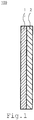
- FIG. 1 is a cross-sectional view of a laminated electrolyte membrane 100 according to the first embodiment.
- the laminated electrolyte membrane 100 illustrated in FIG. 1 includes a hydrocarbon-based electrolyte membrane 1 and a composite electrolyte membrane 2.
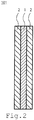
- the hydrocarbon-based electrolyte membrane 1 may be interposed between the composite electrolyte membranes 2.
- the laminated electrolyte membranes 100 and 101 may be laminated with the hydrocarbon-based electrolyte membrane 1 and the composite electrolyte membranes 2. It is preferable that the hydrocarbon-based electrolyte membrane 1 and the composite electrolyte membrane 2 have a laminated structure in direct contact.
- At least a part of a surface facing the composite electrolyte membrane 2 of the hydrocarbon-based electrolyte membrane 1 and at least a part of a surface facing the hydrocarbon-based electrolyte membrane 1 of the composite electrolyte membrane 2 are in direct contact. It is preferable that the whole surface of the surface facing the composite electrolyte membrane 2 of the hydrocarbon-based electrolyte membrane 1 and the whole surface facing the hydrocarbon-based electrolyte membrane 1 of the composite electrolyte membrane 2 are in direct contact with each other for the reason described in the embodiment.
- the thickness of the laminated electrolyte membranes 100 and 101 is preferably 20 ⁇ m or more and 400 ⁇ m or less. It is not preferable that the thickness of the laminated electrolyte membranes 100 and 101 is less than 20 ⁇ m, because the mechanical strength and durability are deteriorated due to the thin membrane. Further, it is not preferable that the thickness of the laminated electrolyte membranes 100 and 101 is thicker than 400 ⁇ m, because membrane resistance becomes high, and the efficiency of water electrolysis is lowered. For the above-described reasons, the thickness of the laminated electrolyte membranes 100 and 101 is more preferably 30 ⁇ m or more and 150 ⁇ m or less, and even more preferably 35 ⁇ m or more and 53 ⁇ m or less.
- gas permeability per unit membrane thickness is preferably smaller than nafion (trademark) of a fluorine-based electrolyte membrane.
- the hydrocarbon-based electrolyte membrane 1 is an electrolyte membrane using a hydrocarbon-based polymer electrolyte which does not contain fluorine as a main chain skeleton and has a heat-resistant main chain skeleton.
- the thickness of the hydrocarbon-based electrolyte membrane 1 is preferably 10 ⁇ m or more and 150 ⁇ m or less, and more preferably 13 ⁇ m or more and 40 ⁇ m or less.
- the hydrocarbon-based polymer electrolyte is preferably a solid polymer electrolyte having a heat-resistant main chain skeleton.
- a polymer having a functional group such as a sulfonic acid group, a carboxylic acid group, a phosphonic acid group, a phosphinic acid group, a sulfonylimide group, and a phenolic hydroxyl group is used.
- hydrocarbon-based polymer electrolyte examples include polyarylene-based, polyetheretherketone-based, polyether sulfone-based, polyphenylene sulfide-based, polyimide-based, and polybenzazole-based polymers in which main chain aromatic rings are sulfonated.
- the hydrocarbon-based electrolyte membrane 1 reinforced with a porous membrane may be used.
- porous membranes include, but are not limited to, polytetrafluoroethylene (PTFE), polyetheretherketone (PEEK), and polypropylene (PP).
- a membrane to which additives are added can also be used to increase chemical durability.
- the additives include a radical scavenger and a radical decomposer.
- an organic phosphorus compound, an aromatic amine-based compound, a phenol-based compound, a thioether-based compound, CeO 2 , and MnO 2 can be used as additives.
- the radical scavenger or hydrogen peroxide decomposer is contained in the hydrocarbon-based electrolyte membrane 1 at a ratio of 0 mass% or more and 10 mass% or less.
- the composite electrolyte membrane 2 is a membrane of a mixture containing a perfluorosulfonic acid-based electrolyte and a superstrong acid metal oxide having an acid function (H0) of -12 or less.
- the composite electrolyte membrane 2 has excellent adhesiveness with the hydrocarbon-based electrolyte membrane 1 and imparts chemical resistance to an electrolyte membrane of a laminated electrolyte membrane. It is preferable that the superstrong acid metal oxide having an acid function (H0) of -12 or less in the composite electrolyte membrane is 20 mass% or more and 80 mass% or less. If the superstrong acid metal oxide is less than 20 mass%, the composite electrolyte membrane 2 laminated with the hydrocarbon-based electrolyte membrane 1 tends to peel off in water.
- the thickness of the composite electrolyte membrane 2 is preferably 10 ⁇ m or more and 200 ⁇ m or less, and more preferably 11 ⁇ m or more and 23 ⁇ m or less.
- the composite electrolyte membrane 2 containing a perfluorosulfonic acid based electrolyte and a superstrong acid metal oxide having an acid function (H0) of -12 or less is excellent in chemical resistance and also excellent in adhesion to the hydrocarbon-based electrolyte membrane 1. Therefore, the laminated electrolyte membranes 100 and 101 according to the embodiment are suitable as a water electrolysis electrolyte membrane.
- the superstrong acid metal oxide is oxide particles in which an oxide of an element Y containing at least one selected from the group consisting of B, S, W, Mo, and V is supported on an oxide of an element X containing at least one selected from the group consisting of Ti, Zr, Si, Sn, and Al.
- the primary particle diameter of the oxide particle is preferably 1 nm or more and 1,000 nm or less, and the average primary particle diameter of the oxide particle is more preferably 4 nm or more and 200 nm or less.
- the oxide of the element Y supported on the oxide of the element X in the superstrong acid metal oxide is preferably 2 mass% or more and 20 mass% or less. It is not preferable that the supported amount is less than 2 mass% because proton conductivity is lowered. On the other hand, it is not preferable that the supported amount exceeds 20 mass% because the oxide component of the supported element Y tends to dissolve.
- oxides of the element X include, but are not limited to, at least one oxide selected from the group consisting of TiO 2 , SiO 2 , ZrO 2 , SnO 2 , SiAl x Oy (0 ⁇ x ⁇ 2, 2 ⁇ y ⁇ 5), SiO-Al 2 O 3 , and TiW ⁇ O ⁇ (0 ⁇ ⁇ ⁇ 1, 2 ⁇ ⁇ ⁇ 5).
- oxides of the element Y include, but are not limited to, at least one oxide selected from the group consisting of SO 4 , BO 3 , WO 3 , VO ⁇ (1 ⁇ 2.5), and MoO 3 .
- Element distribution in the superstrong acid metal oxide is observed and analyzed by analyzing contained elements and contents by an inductively coupled plasma mass spectrometry (ICP-MS) and by mapping them by a scanning electron microscope/energy dispersive X-ray spectroscopy (SEM-EDX).
- ICP-MS inductively coupled plasma mass spectrometry
- SEM-EDX scanning electron microscope/energy dispersive X-ray spectroscopy
- the radical scavenger or the hydrogen peroxide decomposer described in the hydrocarbon-based electrolyte membrane 1 is contained in the composite electrolyte membrane 2 at a ratio of 0 mass% or more and 10 mass% or less.
- the perfluorosulfonic acid-based electrolyte is preferably a polymer having an acidic group such as sulfonic acid group or sulfonamide group in a fluorine-containing main chain skeleton.
- the perfluorosulfonic acid-based electrolyte imparts chemical resistance to the composite electrolyte membrane 2 and structural strength to the composite electrolyte membrane 2.
- Examples of the perfluorosulfonic acid based electrolyte include Nafion (TM, Du Pont), Aquivion (TM, SOLVAY), Flemion (TM, Asahi Kasei Corp.), and Aciplex (TM, Asahi Glass Co., Ltd.).
- a material obtained by dispersing a superstrong acid metal oxide in a perfluorosulfonic acid-based electrolyte dispersion solution is used.
- a solvent to be used for the dispersion may be any one as long as the perfluorosulfonic acid-based electrolyte and the superstrong acid metal oxide are dispersed in a solvent, and a concentration of the solvent may be any concentration as long as coating is possible.
- the solvent examples include, but are not limited to, water; alcohol solvents such as methanol, ethanol, isopropanol, 1-propanol and ethylene glycol; ether solvents such as tetrahydrofuran and dimethoxyethylene; and aprotic polar solvents such as N, N-dimethylformamide, and N-methylpyrrolidone.
- a dispersion solvent a mixed solvent of various solvents may be used.
- an existing method can be used.
- the methods include, but are not limited to, a pane shaker, a ball mill, and an ultrasonic dispersion device.
- the laminated electrolyte membrane 100 is prepared in which the composite electrolyte membrane 2 is formed on the hydrocarbon-based electrolyte membrane 1 by coating and drying the superstrong acid oxide on the hydrocarbon-based electrolyte membrane 1 by using the dispersed perfluorosulfonic acid electrolyte dispersion.
- a coating method any method can be used as long as coating on an electrolyte membrane is possible, and examples of the method include, but are not limited to, a spin coating method, a blade coating method, an inkjet method, a gravure method, and a spray coating method.
- the coated membrane is dried by heating drying, and a temperature thereof is preferably 60°C or more and less than 250°C.
- a drying time can be adjusted according to a used solvent and the membrane thickness of an electrolyte. If the temperature is less than 60°C, the solvent is not sufficiently volatilized, and if the temperature is 250°C or higher, the electrolyte membrane may be decomposed.
- it may be pressurized during heating drying. For example, preferably, in the case of hot pressing, a pressure is in the range where membrane deterioration does not occur, specifically, the pressure is preferably less than 50kg/cm 2 . When the pressure is 50kg/cm 2 or more, a decrease in mechanical strength may occur.
- a roll method can be applied as a pressurized heating drying method.
- a membrane electrode assembly (MEA) includes a first electrode, a second electrode, a hydrocarbon-based electrolyte membrane, and a composite electrolyte membrane.
- the composite electrolyte membrane is laminated with the hydrocarbon-based electrolyte and contains a perfluorosulfonic acid-based electrolyte and a superstrong acid metal oxide having an acid function (H0) of -12 or less.
- the membrane electrode assembly using a laminated electrolyte membrane according to the embodiment is preferable in that, when it is used for water electrolysis, membrane resistance of the electrolyte membrane is low, crossover is low, and resistance is low.
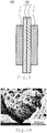
- FIG. 3 is a cross-sectional view of a membrane electrode assembly 200 according to the second embodiment.
- a membrane electrode assembly 200 in FIG. 2 includes a first electrode 3, a second electrode 4, and a laminated electrolyte membrane 100.
- a laminated electrolyte membrane 101 may be used instead of the laminated electrolyte membrane 100.
- the first electrode 3 is a cathode.
- the first electrode 3 includes a catalyst layer in contact with the laminated electrolyte membrane 100 and a support for supporting the catalyst layer.
- the second electrode 4 is an anode.
- the first electrode 3 includes a catalyst layer in contact with the laminated electrolyte membrane 100 and a support for supporting the catalyst layer.
- the catalyst layer according to the embodiment is preferably a carrierless porous catalyst layer.
- a catalyst layer to be used generally includes a supported catalyst in which a catalyst is supported on a surface thereof by using a material such as carbon or a conductive oxide as a support. It has been reported that, although the material of the support hardly contributes to main electrocatalytic reaction, a catalyst material can be controlled for improvement of a reaction area of the catalyst material, and also a pore structure, electric conductivity, ion conductivity and the like can be improved by an electrochemical cell. Carrierless means that a carrier is not used for a catalyst included in a catalyst layer.
- This catalyst layer includes a catalyst unit having a porous structure or a laminated structure including a gap layer.
- FIGS. 4A and 4B illustrate a catalyst unit having a porous structure and a catalyst unit having a laminated structure including a gap layer, respectively.
- FIG. 4A illustrates a catalyst unit having a porous structure.
- FIG. 4B illustrates a catalyst unit having a laminated structure including a gap layer.
- a catalyst is generally nano-sized particles.
- a catalyst in a catalyst unit having a porous structure is sponge-like.
- a catalyst in a catalyst unit having a laminated structure including a gap layer is nanosheet-like.
- a porosity of a catalyst layer is preferably 50 to 90 vol.%. In addition, if the porosity of the catalyst layer is within this range, the substances can be sufficiently moved without lowering the utilization efficiency of a noble metal.
- the predetermined catalyst material used for the carrierless catalyst layer according to the embodiment contains at least one selected from the group consisting of noble metal elements such as Pt, Ru, Rh, Os, Ir, Pd, and Au. Such the catalyst material is excellent in catalytic activity, conductivity, and stability.
- the above-described metal may be used as an oxide and may be a composite oxide or mixed oxide containing two or more kinds of metals.
- An optimum noble metal element can be appropriately selected in accordance with a reaction in which the MEA is used.
- a catalyst having a composition represented by Pt u M 1-u is desirable.
- u is 0 ⁇ u ⁇ 1
- an element M is at least one selected from the group consisting of Co, Ni, Fe, Mn, Ta, W, Hf, Si, Mo, Ti, Zr, Nb, V, Cr, Al, and Sn.
- This catalyst contains Pt of more than 0 atomic% and 90 atomic% or less and the element M of 10 atomic% or more and less than 100 atomic%.
- an oxide catalyst containing at least Ir an oxide catalyst containing at least one of Pt, Ru, and Ir, a metal catalyst containing any one of Pt, Ru, and Ir, or an alloy catalyst containing any one of Pt, Ru, and Ir is desirable.
- the oxide catalyst is, for example, a catalyst having a composition represented by Ir z M 1-z O.
- z is 0.5 ⁇ z
- the element M is at least selected from the group consisting of Co, Ni, Fe, Mn, Ta, W, Hf, Si, Mo, Ti, Zr, Nb, V, Cr, Sr, and Sn.
- This oxide catalyst contains the element M of 50 atomic% or more or 0 atomic% or more and less than 50 atomic% in the case of considering only a metal component element.
- an oxide catalyst include an oxide catalyst including metal of at least one selected from the group consisting of Pt, Ru, and Ir of at least one selected from the group consisting of IrO 2 , RuO 2 , IrRu x O y , IrNi x O y , IrSr x O y , and IrRu x Ni y O z and arbitrary one or more elements M.
- an anode catalyst of the MEA in which the laminated electrolyte membrane 100 according to the embodiment is used is not limited to the above.
- a catalyst layer precursor is formed on a support by sputtering or evaporating a catalyst material and a pore-forming agent material at the same time.
- the pore forming agent is removed to obtain an electrode.
- a catalyst layer precursor is formed on a support by alternately sputtering or evaporating a material containing a catalyst material and a pore-forming agent material.
- the pore forming agent is removed to obtain an electrode.
- the MEA according to the embodiment is prepared by combining an electrolyte membrane by using the above-described catalyst layer as at least either of the first electrode 3 or the second electrode 4.
- the catalyst layer and the electrolyte membrane are bonded by heating and pressurizing.
- the electrolyte membrane 100 is sandwiched with a support containing the catalyst layer and laminated as indicated in FIG. 3 and joined to obtain the MEA 200.
- the forming support of the catalyst layer is a transfer substrate
- the catalyst layer is transferred from the transfer substrate to the electrolyte membrane 100
- the catalyst layer is transferred to the electrolyte membrane 100
- the membrane catalyst layer assembly (catalyst coated membrane (CCM)) is prepared.
- the CCM is laminated as indicated in FIG. 3 by sandwiching two gas diffusion supports and bonded by heating and pressuring to obtain the MEA 200.
- the gas diffusion layer may be disposed on the catalyst layer. These are laminated as indicated in FIG. 3 and joined by heating and pressurizing to obtain the MEA 200.
- a water electrolysis cell includes a membrane electrode assembly, a cathode feed conductor, a separator, a gasket (seal), an anode feed conductor, a separator, and a gasket (seal).
- the membrane electrode assembly includes a first electrode, a second electrode, a hydrocarbon-based electrolyte membrane, and a composite electrolyte membrane.
- the composite electrolyte membrane is laminated with the hydrocarbon-based electrolyte membrane and contains a perfluorosulfonic acid-based electrolyte and a superstrong acid metal oxide having an acid function (H0) of -12 or less.
- the water electrolysis cell using a laminated electrolyte membrane according to the embodiment is preferable in that, when it is used for water electrolysis, membrane resistance of the electrolyte membrane is low, crossover is low, and resistance is low.
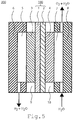
- FIG. 5 is a cross-sectional view of a water electrolysis cell 300 according to the third embodiment.
- the water electrolysis cell 300 illustrated in FIGS. 4A to 4D includes a first electrode (cathode) 3, a second electrode (anode) 4, a laminated electrolyte membrane 100, a cathode feed conductor 5, a separator 6, an anode feed conductor 7, a separator 8, a gasket (seal) 9, and a gasket (seal) 10.
- a laminated electrolyte membrane 101 may be used. Any type of anode feed conductors and cathode feed conductors may be used as long as gas and water can pass through.
- each of the feed conductors may be integrated with a separator.
- the feed conductor is, for example, a feed conductor having a flow path through which water or gas flows in a separator and a feed conductor having a porous body, but is not limited thereto.
- an electrode (not illustrated) is connected to the cathode feed conductor 5 and the anode feed conductor 7, and a reaction occurs between the cathode and the anode.
- Water is supplied to the anode, and water is decomposed into protons, oxygen and electrons at the anode electrode.
- a support of the electrode and the feed conductor are porous bodies, and this porous body functions as a flow path plate.
- the generated water and unreacted water are discharged, and protons and electrons are used in a cathode reaction through the laminated electrolyte membrane 100.
- protons and electrons react to produce hydrogen. Either one or both of the generated hydrogen and oxygen are used, for example, as fuel for a fuel cell.
- a membrane electrode assembly is held by the separators 6 and 8, and airtightness is maintained by gaskets (seals) 9 and 10.
- the laminated electrolyte membrane 100 according to the embodiment is difficult to separate in water and therefore excellent in durability.
- the laminated electrolyte membrane 100 according to the embodiment is excellent in chemical resistance and has low membrane resistance, and therefore has low crossover and is excellent in decomposition efficiency.
- a plurality of membrane electrode assemblies 200 or a plurality of water electrolysis cells is connected in series in a stack 400 according to a fourth embodiment illustrated in FIG. 6 .
- Tightening plates 11 and 12 are attached to both ends of the water electrolysis cell.
- a fifth embodiment relates to a water electrolysis apparatus.
- a stack 400 according to the embodiment is used.
- the water electrolysis apparatus will be described with reference to a schematic diagram in FIG. 7 .
- Water electrolysis single cells illustrated in FIG. 7 laminated in series are used as the water electrolysis stack 400.
- a power source 18 is attached to the water electrolysis stack 400, and a voltage is applied between an anode and a cathode.
- a gas-liquid separator 15 for separating generated gas and unreacted water and a mixing tank 14 are connected.
- a pump 19 from an ion exchange water manufacturing device 13 which supplies water, and the water is circulated to the anode by mixing in the mixing tank 14 from the gas-liquid separator 15 through a check valve 20. Oxygen generated at the anode passes through the gas-liquid separator 15, and oxygen gas is obtained.
- a hydrogen purification device 17 is continuously connected to a gas-liquid separator 16 to obtain high purity hydrogen. Impurities are discharged via a path including a valve 21 connected to the hydrogen purification device 17. To stably control an operating temperature, it is possible to control heating of the stack and the mixing tank and a current density during thermal decomposition.
- a coating solution for a composite membrane is adjusted by adding 20 g of ethanol to a predetermined amount of a fluorine-based electrolyte dispersion (20% nafion dispersion solution, Du Pont) in a polyhot, adding a superstrong acid oxide and a predetermined amount thereof, and adding 40 zirconia balls (diameter 5 mm), and dispersing them for 10 minutes by using Rentaro (Thinky Corporation).
- Compositions of the prepared dispersion in examples 1 to 11 and comparative examples 1 to 4 are summarized in Table 1.
- decomposer hydrogen peroxide decomposer
- aqueous solution is adjusted in which hexammonium heptamolybdate tetrahydrate (manufactured by Wako Pure Chemical Industries, Ltd.) (NH 4 ) 6 Mo 7 O 24 , 4H 2 O is dissolved in water.
- the aqueous solution is mixed with a dispersion (containing 2 mL of concentrated HCl) in which titanium oxide (Super Titania F-6 and F-4, made by Showa Denko K.K.) TiO 2 is dispersed in water.
- the mixture is evaporated to dryness at 80°C to support ammonium molybdate on TiO 2 .
- the obtained precursor is dried at 100°C for 6H and then calcined at 600°C for 4H, and ammonium molybdate is thermally decomposed to obtain MoO 3 /TiO 2 .
- the composition of MoO 3 /TiO 2 is 5/95 by a weight ratio.
- tungsten oxide (Wako Pure Chemical Industries, Ltd.) WO 3 is dissolved in heated condensed ammonia aqueous solution (made by Wako Pure Chemical Industries, Ltd., 15% aqueous solution).
- This aqueous solution is mixed with a dispersion in which titanium oxide (Super Titania F- 6 Showa Denko K.K.) TiO 2 is dispersed in water.
- This aqueous solution is evaporated to dryness at 80°C to support ammonium tungstate on TiO 2 .
- the obtained precursor is dried at 100°C for 6H and then calcined at 700°C for 4H, and ammonium tungstate is thermally decomposed to obtain WO 3 /TiO 2 .
- compositions of WO 3 /TiO 2 at a weight ratio of 5/95 and 10/90 are prepared.
- An aqueous solution is adjusted in which ammonium metavanadate (Wako Pure Chemical Industries, Ltd.) (NH 4 )VO 3 is dissolved in hot water.
- the aqueous solution is mixed with a dispersion (containing 2 mL of concentrated HCl) in which titanium oxide (Super Titania F-6 and F-4, Showa Denko K.K.) TiO 2 is dispersed in water.
- the mixture was evaporated to dryness at 80°C to support ammonium metavanadate on TiO 2 .
- the obtained precursor was dried at 100 °C for 6H and then calcined at 600°C for 4H, and ammonium metavanadate is thermally decomposed to obtain VO 3 /TiO 2 .
- the composition of MoO 3 /TiO 2 is 5/95 by a weight ratio.
- aqueous solution is adjusted in which tungsten oxide (Wako Pure Chemical Industries, Ltd.) WO 3 is dissolved in heated condensed ammonia aqueous solution (Wako Pure Chemical Industries, 15% aqueous solution).
- This aqueous solution is mixed with a dispersion in which zirconium oxide (Wako Pure Chemical Industries, Ltd.) ZrO 2 is dispersed in water.
- This aqueous solution is evaporated to dryness at 80°C to support ammonium tungstate on TiO 2 .
- the obtained precursor is dried at 100°C for 6H and then calcined at 700°C for 4H, and ammonium tungstate is thermally decomposed to obtain WO 3 /TiO 2 .
- compositions of WO 3 /TiO 2 at a weight ratio of 5/95 and 20/90 are prepared.
- a dispersion of titanium oxide is adjusted by mixing 9.500g of titanium oxide (TiO 2 , Tayca, AMT-100) and 300 mL of water in a 1,000 mL beaker. Evaporation to dryness is performed by mixing 0.521g of concentrated sulfuric acid (96%) with this dispersion, further adding water to make the total volume 400 mL, and stirring the solution by a hot stirrer set at 140°C.
- a precursor is pulverized and passed through a 106 ⁇ m sieve, placed on a baking dish, and fired at 600°C for 3 hours to obtain sulfuric acid-supported titanium oxide SO 4 /TiO 2 . Composition analysis by ICP analysis reveals that S is 0.64% (1.92% in terms of SO 4 ), TiO 2 is 95.0%, and the rest is moisture. Therefore, the SO 4 supporting amount is 2.0% in a state where moisture is removed.
- a dispersion of titanium oxide is adjusted by mixing 9. 500g of zirconium oxide (made by Wako Pure Chemical Industries, Ltd.) and 300 mL of water in a 1000 mL beaker. Evaporation to dryness is performed by mixing 1.01g of concentrated sulfuric acid (96%) with this dispersion, further adding water to make the total volume 400 mL, and stirring the solution by a hot stirrer set at 140°C.
- a precursor is pulverized and passed through a 106 ⁇ m sieve, placed on a baking dish, and fired at 600°C for 3 hours to obtain sulfuric acid-supported titanium oxide SO 4 /TiO 2 .
- a composite laminated membrane is prepared by spraying the above-described adjusted dispersion for a composite membrane on various membrane thickness aromatic hydrocarbon-based electrolyte membranes (EW ⁇ 400), drying the membranes at 60°C for 10 minutes, drying at 130°C for 10 minutes, and further drying at 180°C for 10 minutes while pressurizing at 10 kg/cm 2 .
- Table 2 indicates the prepared various membranes in examples 12 to 25 and comparative examples 5 to 10.
- a three-layered laminated membrane (comparative example 11) is prepared by stacking a naf ion HP membrane, a 13 ⁇ m membrane of the aromatic hydrocarbon-based electrolyte membrane, and a nafion HP membrane in this order and heating and compressing them at 180°C for 10 minutes while pressurizing to 10 kg/cm 2 .
- Ion exchanged water is sufficiently poured in a beaker, and an immersion test is performed in which the above-described prepared composite laminated membrane is immersed for 5 minutes at room temperature.
- Table 2 the case where the membrane is peeled off at an interface of the laminated membrane is marked with x, and the case where the membrane is not peeled off is marked with o.
- An anode electrode is prepared by sputtering IrNi x O y and a gap agent by reactive sputtering on a 200 ⁇ m-thick titanium porous body, and etching, heating, and drying after acid treatment.
- An IrNi x O y catalyst layer is an Ir amount of 0.15 mg/cm 2 (22 layers).
- a cathode electrode is prepared by etching with acid and heating and drying after washing with water after sputtering on a Carpon Paper with a cathode electrode MPL (microporous layer).
- a PtCo alloy catalyst is a platinum amount of 0.18 mg/cm 2 (28 layers).
- Each of the anode electrode and the cathode electrode are cut to 20 mm square each.
- the anode electrode, a laminated electrolyte membrane, and the cathode electrode are sequentially stacked and pressure-bonded by hot pressing (50 kg, 165°C, 4 minutes), and then cooled to room temperature to prepare an MEA.
- the process is summarized in Table 3. However, when the composite laminated membrane has two layers, an aromatic hydrocarbon-based electrolyte membrane side is prepared as a cathode electrode side.
- An MEA (comparative example 12) is prepared by using nafion 115 as a membrane in the same manner as preparation conditions for the above-described MEA.
- a flow channel plate of titanium is used, and a single cell (anode & cathode; straight channel) having an electrode area of 4 cm 2 is used.
- the cell temperature is 80°C at atmospheric pressure, and the temperature is maintained by heating by a heater, and ion-exchanged water is used by circulating, to the anode, several times the amount of water necessary for water decomposition.
- Water electrolysis is performed at a cell temperature of 80°C by using an electronic load device manufactured by Kikusui Corporation at a current density of 2 A/cm 2 . Decomposition voltages of water and AC impedance resistance at 1 KHz in such a case are summarized in Table 3.
- the MEA using the composite membrane is highly efficient because crossover is low, membrane resistance is low, and a voltage is low in comparison with the comparative example 12 in which nafion 115, standard used in PEM type water electrolysis, is used.
Landscapes
- Chemical & Material Sciences (AREA)
- Engineering & Computer Science (AREA)
- Chemical Kinetics & Catalysis (AREA)
- Electrochemistry (AREA)
- Materials Engineering (AREA)
- Metallurgy (AREA)
- Organic Chemistry (AREA)
- Inorganic Chemistry (AREA)
- Electrolytic Production Of Non-Metals, Compounds, Apparatuses Therefor (AREA)
- Fuel Cell (AREA)
Abstract
A laminated electrolyte membrane of an embodiment includes: a hydrocarbon-based electrolyte membrane; and a composite electrolyte membrane laminated with the hydrocarbon-based electrolyte, the composite electrolyte membrane containing a perfluorosulfonic acid-based electrolyte and a superstrong acid metal oxide having an acid function (H0) of -12 or less.
Description
- Embodiments described herein relate to a laminated electrolyte membrane, a membrane electrode assembly, a water electrolysis cell, a stack, and a water electrolysis apparatus.
- Currently, fuel cells are attracting attention and being developed as a clean power generation system that can reduce environmental load. In particular, the fuel cells are beginning to be used in various fields such as home use power supply fuel cells (Enefarm (TM)), on-vehicle fuel cells, buses, and trains. On the other hand, it is essential to reduce CO2 emissions as measures to prevent global warming, and renewable energy such as solar batteries and wind power generators is actively utilized as clean energy that does not emit CO2. Producible energy of these types of renewable energy is greatly influenced by weather. Therefore, such renewable energy is considered as a stable power supply system such as a power storage by a secondary battery or return to chemical energy by compound synthesis.
- In recent years, a "hydrogen society" has been proposed in a clean energy supply system that produces hydrogen from renewable energy and generates power by using a fuel cell. From these facts, hydrogen is attracting attention for returning from electric energy to a compound (chemical energy), and examples of a method for producing hydrogen include alkaline water electrolysis, solid polymer electrolyte (PEM) type water electrolysis, and solid oxide type water electrolysis (SOEC). Recently, PEM type water electrolysis has been extensively studied as highly efficient water electrolysis.
- For example, in a PEM type water electrolysis apparatus, a platinum group metal is bonded to both sides of a solid polymer electrolyte membrane (fluororesin based cation exchange membrane) so as to be integrated with a membrane, one side is an anode, and the other side is a cathode. When a DC voltage is applied between the electrodes while supplying water to the anode side, oxygen gas is generated from the anode, and hydrogen gas is generated from the cathode. The polymer electrolyte membrane functions as a diaphragm, and the generated hydrogen gas and oxygen gas can be taken out separately.
- In order to improve the performance of PEM type water electrolysis, it is necessary to reduce membrane resistance by improving proton conductivity of the electrolyte membrane. However, although thinning the electrolyte membrane improves the conductivity, in addition to a problem that crossover of oxygen from the anode to the cathode and crossover of hydrogen from the cathode to the anode greatly increase, a reduction in mechanical strength is a problem.
- In the polymer electrolyte membrane, a fluorine-based electrolyte membrane being used at present is reducing the resistance by thinning. However, the reduction in mechanical strength and an increase in gas permeability are maj or problems. As an electrolyte membrane used for a water electric field, a hydrocarbon-based electrolyte membrane is known besides a fluorine-based electrolyte membrane. In the hydrocarbon-based electrolyte membrane, gas permeability is about several minutes or less that is less than that of the fluorine-based electrolyte membrane. However, the hydrocarbon-based electrolyte membrane has radical resistance significantly lower than that of the fluorine-based electrolyte membrane and has low durability. In such a current situation, a water electrolysis electrolyte membrane having high performance and durability and a membrane electrode assembly using the same are required for further improvement in performance.
-
-
FIG. 1 is a cross-sectional view of a laminated electrolyte membrane according to embodiments described herein; -
FIG. 2 is a cross-sectional view of a laminated electrolyte membrane according to the embodiments; -
FIG. 3 is a cross-sectional view of a membrane electrode assembly according to the embodiments; -
FIGS. 4A ,4B ,4C , and4D are low magnification transmission-type microphotographs of a catalyst cross section according to the embodiments; -
FIG. 5 is a cross-sectional view of a water electrolysis cell according to the embodiments; -
FIG. 6 is a cross-sectional view of a stack according to the embodiments; and -
FIG. 7 is a schematic diagram of a water electrolysis apparatus according to the embodiments. - A laminated electrolyte membrane of an embodiment includes: a hydrocarbon-based electrolyte membrane; and a composite electrolyte membrane laminated with the hydrocarbon-based electrolyte, the composite electrolyte membrane containing a perfluorosulfonic acid-based electrolyte and a superstrong acid metal oxide having an acid function (H0) of -12 or less.
- Hereinafter, embodiments will be described in detail with reference to the drawings. In the following description, same members are denoted by same reference signs, and description of such as members once described is omitted as appropriate.
- A laminated electrolyte membrane according to a first embodiment includes a hydrocarbon-based electrolyte membrane and a composite electrolyte membrane. The composite electrolyte membrane is laminated with the hydrocarbon-based electrolyte and contains a perfluorosulfonic acid-based electrolyte and a superstrong acid metal oxide having an acid function (H0) of -12 or less. When the laminated electrolyte membrane according to the embodiment is used as a water electrolysis electrolyte membrane, it is preferable in view of low membrane resistance of the electrolyte membrane, low crossover, and low resistance.
-
FIG. 1 is a cross-sectional view of a laminatedelectrolyte membrane 100 according to the first embodiment. The laminatedelectrolyte membrane 100 illustrated inFIG. 1 includes a hydrocarbon-basedelectrolyte membrane 1 and acomposite electrolyte membrane 2. As in a laminatedelectrolyte membrane 101 illustrated inFIG. 2 , the hydrocarbon-basedelectrolyte membrane 1 may be interposed between thecomposite electrolyte membranes 2. The laminatedelectrolyte membranes electrolyte membrane 1 and thecomposite electrolyte membranes 2. It is preferable that the hydrocarbon-basedelectrolyte membrane 1 and thecomposite electrolyte membrane 2 have a laminated structure in direct contact. At least a part of a surface facing thecomposite electrolyte membrane 2 of the hydrocarbon-basedelectrolyte membrane 1 and at least a part of a surface facing the hydrocarbon-basedelectrolyte membrane 1 of thecomposite electrolyte membrane 2 are in direct contact. It is preferable that the whole surface of the surface facing thecomposite electrolyte membrane 2 of the hydrocarbon-basedelectrolyte membrane 1 and the whole surface facing the hydrocarbon-basedelectrolyte membrane 1 of thecomposite electrolyte membrane 2 are in direct contact with each other for the reason described in the embodiment. - The thickness of the laminated
electrolyte membranes electrolyte membranes electrolyte membranes electrolyte membranes - In the hydrocarbon-based
electrolyte membrane 1, gas permeability per unit membrane thickness is preferably smaller than nafion (trademark) of a fluorine-based electrolyte membrane. The hydrocarbon-basedelectrolyte membrane 1 is an electrolyte membrane using a hydrocarbon-based polymer electrolyte which does not contain fluorine as a main chain skeleton and has a heat-resistant main chain skeleton. The thickness of the hydrocarbon-basedelectrolyte membrane 1 is preferably 10 µm or more and 150 µm or less, and more preferably 13 µm or more and 40 µm or less. - The hydrocarbon-based polymer electrolyte is preferably a solid polymer electrolyte having a heat-resistant main chain skeleton. For the hydrocarbon-based polymer electrolyte, a polymer having a functional group such as a sulfonic acid group, a carboxylic acid group, a phosphonic acid group, a phosphinic acid group, a sulfonylimide group, and a phenolic hydroxyl group is used. Specific examples of the hydrocarbon-based polymer electrolyte include polyarylene-based, polyetheretherketone-based, polyether sulfone-based, polyphenylene sulfide-based, polyimide-based, and polybenzazole-based polymers in which main chain aromatic rings are sulfonated.
- Furthermore, in order to increase the mechanical strength of these electrolyte membranes, the hydrocarbon-based
electrolyte membrane 1 reinforced with a porous membrane may be used. Examples of specific porous membranes include, but are not limited to, polytetrafluoroethylene (PTFE), polyetheretherketone (PEEK), and polypropylene (PP). Further, a membrane to which additives are added can also be used to increase chemical durability. Examples of the additives include a radical scavenger and a radical decomposer. For example, an organic phosphorus compound, an aromatic amine-based compound, a phenol-based compound, a thioether-based compound, CeO2, and MnO2 can be used as additives. The radical scavenger or hydrogen peroxide decomposer is contained in the hydrocarbon-basedelectrolyte membrane 1 at a ratio of 0 mass% or more and 10 mass% or less. - The
composite electrolyte membrane 2 is a membrane of a mixture containing a perfluorosulfonic acid-based electrolyte and a superstrong acid metal oxide having an acid function (H0) of -12 or less. Thecomposite electrolyte membrane 2 has excellent adhesiveness with the hydrocarbon-basedelectrolyte membrane 1 and imparts chemical resistance to an electrolyte membrane of a laminated electrolyte membrane. It is preferable that the superstrong acid metal oxide having an acid function (H0) of -12 or less in the composite electrolyte membrane is 20 mass% or more and 80 mass% or less. If the superstrong acid metal oxide is less than 20 mass%, thecomposite electrolyte membrane 2 laminated with the hydrocarbon-basedelectrolyte membrane 1 tends to peel off in water. Therefore, it becomes difficult to use as a water electrolysis electrolyte. It is not preferable that the hydrocarbon-basedelectrolyte membrane 1 and thecomposite electrolyte membrane 2 are peeled off in water, because an electrolysis voltage rises. On the other hand, it is not preferable that the superstrong acid metal oxide exceeds 80 mass%, because membrane resistance increases, and it becomes difficult to maintain a membrane structure. The thickness of thecomposite electrolyte membrane 2 is preferably 10 µm or more and 200 µm or less, and more preferably 11 µm or more and 23 µm or less. - In water electrolysis, hydrogen peroxide, hydroxy radicals and the like are generated during electrolysis, and a membrane is likely to be easily destructed chemically. Therefore, if the hydrocarbon-based
electrolyte membrane 1 is used alone, there is a problem in durability. An electrolyte membrane using a perfluorosulfonic acid-based electrolyte is excellent in chemical resistance. However, when laminated with the hydrocarbon-basedelectrolyte membrane 1, the electrolyte membrane is easily peeled off in water. Therefore, although there is not much problem for use in a fuel cell, it cannot be used for a water electrolysis electrolyte membrane. Thecomposite electrolyte membrane 2 containing a perfluorosulfonic acid based electrolyte and a superstrong acid metal oxide having an acid function (H0) of -12 or less is excellent in chemical resistance and also excellent in adhesion to the hydrocarbon-basedelectrolyte membrane 1. Therefore, thelaminated electrolyte membranes - The superstrong acid metal oxide is oxide particles in which an oxide of an element Y containing at least one selected from the group consisting of B, S, W, Mo, and V is supported on an oxide of an element X containing at least one selected from the group consisting of Ti, Zr, Si, Sn, and Al. The primary particle diameter of the oxide particle is preferably 1 nm or more and 1,000 nm or less, and the average primary particle diameter of the oxide particle is more preferably 4 nm or more and 200 nm or less.
- The oxide of the element Y supported on the oxide of the element X in the superstrong acid metal oxide is preferably 2 mass% or more and 20 mass% or less. It is not preferable that the supported amount is less than 2 mass% because proton conductivity is lowered. On the other hand, it is not preferable that the supported amount exceeds 20 mass% because the oxide component of the supported element Y tends to dissolve.
- Specific examples of the oxides of the element X include, but are not limited to, at least one oxide selected from the group consisting of TiO2, SiO2, ZrO2, SnO2, SiAlxOy (0 < x ≤ 2, 2 < y ≤ 5), SiO-Al2O3, and TiWαOβ (0 < α ≤ 1, 2 < β ≤ 5).
- Specific examples of the oxides of the element Y include, but are not limited to, at least one oxide selected from the group consisting of SO4, BO3, WO3, VOγ (1≤γ≤2.5), and MoO3.
- Element distribution in the superstrong acid metal oxide is observed and analyzed by analyzing contained elements and contents by an inductively coupled plasma mass spectrometry (ICP-MS) and by mapping them by a scanning electron microscope/energy dispersive X-ray spectroscopy (SEM-EDX). In addition, it is preferable to use an X-ray diffractometer for specifying the oxide.
- The radical scavenger or the hydrogen peroxide decomposer described in the hydrocarbon-based
electrolyte membrane 1 is contained in thecomposite electrolyte membrane 2 at a ratio of 0 mass% or more and 10 mass% or less. - The perfluorosulfonic acid-based electrolyte is preferably a polymer having an acidic group such as sulfonic acid group or sulfonamide group in a fluorine-containing main chain skeleton. The perfluorosulfonic acid-based electrolyte imparts chemical resistance to the
composite electrolyte membrane 2 and structural strength to thecomposite electrolyte membrane 2. Examples of the perfluorosulfonic acid based electrolyte include Nafion (TM, Du Pont), Aquivion (TM, SOLVAY), Flemion (TM, Asahi Kasei Corp.), and Aciplex (TM, Asahi Glass Co., Ltd.). - For preparing a composite membrane including a perfluorosulfonic acid based electrolyte and a superstrong acid metal oxide, a material obtained by dispersing a superstrong acid metal oxide in a perfluorosulfonic acid-based electrolyte dispersion solution is used. A solvent to be used for the dispersion may be any one as long as the perfluorosulfonic acid-based electrolyte and the superstrong acid metal oxide are dispersed in a solvent, and a concentration of the solvent may be any concentration as long as coating is possible. Examples of the solvent include, but are not limited to, water; alcohol solvents such as methanol, ethanol, isopropanol, 1-propanol and ethylene glycol; ether solvents such as tetrahydrofuran and dimethoxyethylene; and aprotic polar solvents such as N, N-dimethylformamide, and N-methylpyrrolidone. As a dispersion solvent, a mixed solvent of various solvents may be used.
- As a method for dispersing the superstrong acid oxide in the perfluorosulfonic acid-based electrolyte dispersion solution, an existing method can be used. Examples of the methods include, but are not limited to, a pane shaker, a ball mill, and an ultrasonic dispersion device.
- Next, the
laminated electrolyte membrane 100 is prepared in which thecomposite electrolyte membrane 2 is formed on the hydrocarbon-basedelectrolyte membrane 1 by coating and drying the superstrong acid oxide on the hydrocarbon-basedelectrolyte membrane 1 by using the dispersed perfluorosulfonic acid electrolyte dispersion. Regarding a coating method, any method can be used as long as coating on an electrolyte membrane is possible, and examples of the method include, but are not limited to, a spin coating method, a blade coating method, an inkjet method, a gravure method, and a spray coating method. - The coated membrane is dried by heating drying, and a temperature thereof is preferably 60°C or more and less than 250°C. A drying time can be adjusted according to a used solvent and the membrane thickness of an electrolyte. If the temperature is less than 60°C, the solvent is not sufficiently volatilized, and if the temperature is 250°C or higher, the electrolyte membrane may be decomposed. In addition, to further improve adhesion of the membrane, it may be pressurized during heating drying. For example, preferably, in the case of hot pressing, a pressure is in the range where membrane deterioration does not occur, specifically, the pressure is preferably less than 50kg/cm2. When the pressure is 50kg/cm2 or more, a decrease in mechanical strength may occur. In addition, a roll method can be applied as a pressurized heating drying method.
- A membrane electrode assembly (MEA) according to a second embodiment includes a first electrode, a second electrode, a hydrocarbon-based electrolyte membrane, and a composite electrolyte membrane. The composite electrolyte membrane is laminated with the hydrocarbon-based electrolyte and contains a perfluorosulfonic acid-based electrolyte and a superstrong acid metal oxide having an acid function (H0) of -12 or less. The membrane electrode assembly using a laminated electrolyte membrane according to the embodiment is preferable in that, when it is used for water electrolysis, membrane resistance of the electrolyte membrane is low, crossover is low, and resistance is low.
-
FIG. 3 is a cross-sectional view of amembrane electrode assembly 200 according to the second embodiment. Amembrane electrode assembly 200 inFIG. 2 includes afirst electrode 3, asecond electrode 4, and alaminated electrolyte membrane 100. Instead of thelaminated electrolyte membrane 100, alaminated electrolyte membrane 101 may be used. - The
first electrode 3 is a cathode. Thefirst electrode 3 includes a catalyst layer in contact with thelaminated electrolyte membrane 100 and a support for supporting the catalyst layer. Thesecond electrode 4 is an anode. Thefirst electrode 3 includes a catalyst layer in contact with thelaminated electrolyte membrane 100 and a support for supporting the catalyst layer. - The catalyst layer according to the embodiment is preferably a carrierless porous catalyst layer. To obtain high cell characteristics, a catalyst layer to be used generally includes a supported catalyst in which a catalyst is supported on a surface thereof by using a material such as carbon or a conductive oxide as a support. It has been reported that, although the material of the support hardly contributes to main electrocatalytic reaction, a catalyst material can be controlled for improvement of a reaction area of the catalyst material, and also a pore structure, electric conductivity, ion conductivity and the like can be improved by an electrochemical cell. Carrierless means that a carrier is not used for a catalyst included in a catalyst layer. This catalyst layer includes a catalyst unit having a porous structure or a laminated structure including a gap layer. In the case of using a noble metal catalyst, it is possible to maintain high characteristics and high durability of an electrochemical cell even when a small amount of a noble metal catalyst is used.
FIGS. 4A and4B illustrate a catalyst unit having a porous structure and a catalyst unit having a laminated structure including a gap layer, respectively.FIG. 4A illustrates a catalyst unit having a porous structure.FIG. 4B illustrates a catalyst unit having a laminated structure including a gap layer. In the case where a catalyst material is supported on a carrier, a catalyst is generally nano-sized particles. However, a catalyst in a catalyst unit having a porous structure is sponge-like. A catalyst in a catalyst unit having a laminated structure including a gap layer is nanosheet-like. By using a sponge-like or nanosheet-like catalyst, it is possible to improve characteristics of an electrochemical cell. An electrocatalytic reaction occurs on a catalyst surface, and therefore a catalyst shape affects atomic arrangement and electronic state of the catalyst surface. In a catalyst unit having a laminated structure including a gap layer, adjacent nanosheets are desirably partially integrated. Although a mechanism has not yet been elucidated completely, it is thought that proton conduction or hydrogen atom conduction for electrode reaction can be achieved more smoothly. Further, as indicated inFIG. 4C , higher properties can be obtained by making a nanosheet inside the laminated structure porous. This is because gas diffusion and water management can be improved. Durability and robustness can be further improved by disposing a porous nano-carbon layer (FIG. 4D ) containing fibrous carbon or a nanoceramic material layer between the nanosheets inside the laminated structure. The catalyst contributing to main electrode reaction is hardly supported by fibrous carbon contained in the porous nano-carbon layer, and therefore a laminated structural unit including the porous nano-carbon layer is considered to be carrierless. Here, since the movement of substances such as discharge of moisture becomes smoother, a porosity of a catalyst layer is preferably 50 to 90 vol.%. In addition, if the porosity of the catalyst layer is within this range, the substances can be sufficiently moved without lowering the utilization efficiency of a noble metal. - The predetermined catalyst material used for the carrierless catalyst layer according to the embodiment contains at least one selected from the group consisting of noble metal elements such as Pt, Ru, Rh, Os, Ir, Pd, and Au. Such the catalyst material is excellent in catalytic activity, conductivity, and stability. The above-described metal may be used as an oxide and may be a composite oxide or mixed oxide containing two or more kinds of metals.
- An optimum noble metal element can be appropriately selected in accordance with a reaction in which the MEA is used.
- For example, when a hydrogen production reaction is needed as a water electrolysis cathode, a catalyst having a composition represented by PtuM1-u is desirable. Here, u is 0 < u ≤ 1, and an element M is at least one selected from the group consisting of Co, Ni, Fe, Mn, Ta, W, Hf, Si, Mo, Ti, Zr, Nb, V, Cr, Al, and Sn. This catalyst contains Pt of more than 0 atomic% and 90 atomic% or less and the element M of 10 atomic% or more and less than 100 atomic%.
- On the other hand, when an oxidation reaction of water (oxygen evolution reaction) is required as a water electrolysis anode, an oxide catalyst containing at least Ir, an oxide catalyst containing at least one of Pt, Ru, and Ir, a metal catalyst containing any one of Pt, Ru, and Ir, or an alloy catalyst containing any one of Pt, Ru, and Ir is desirable. The oxide catalyst is, for example, a catalyst having a composition represented by IrzM1-zO. Here, z is 0.5 < z, and the element M is at least selected from the group consisting of Co, Ni, Fe, Mn, Ta, W, Hf, Si, Mo, Ti, Zr, Nb, V, Cr, Sr, and Sn. This oxide catalyst contains the element M of 50 atomic% or more or 0 atomic% or more and less than 50 atomic% in the case of considering only a metal component element. Specific examples of an oxide catalyst include an oxide catalyst including metal of at least one selected from the group consisting of Pt, Ru, and Ir of at least one selected from the group consisting of IrO2, RuO2, IrRuxOy, IrNixOy, IrSrxOy, and IrRuxNiyOz and arbitrary one or more elements M. However, an anode catalyst of the MEA in which the
laminated electrolyte membrane 100 according to the embodiment is used is not limited to the above. - A method for manufacturing a carrierless porous catalyst layer according to the embodiment will be briefly described.
- First, in the case of manufacturing a catalyst layer having a catalyst unit, a catalyst layer precursor is formed on a support by sputtering or evaporating a catalyst material and a pore-forming agent material at the same time. Next, the pore forming agent is removed to obtain an electrode. In the case of manufacturing a catalyst layer having a unit having a laminate structure including a gap layer, a catalyst layer precursor is formed on a support by alternately sputtering or evaporating a material containing a catalyst material and a pore-forming agent material. Next, the pore forming agent is removed to obtain an electrode.
- The MEA according to the embodiment is prepared by combining an electrolyte membrane by using the above-described catalyst layer as at least either of the
first electrode 3 or thesecond electrode 4. In general, the catalyst layer and the electrolyte membrane are bonded by heating and pressurizing. In this case, in the case where a forming support of the catalyst layer is a gas diffusion layer, theelectrolyte membrane 100 is sandwiched with a support containing the catalyst layer and laminated as indicated inFIG. 3 and joined to obtain theMEA 200. - Further, in the case where the forming support of the catalyst layer is a transfer substrate, first, the catalyst layer is transferred from the transfer substrate to the
electrolyte membrane 100, the catalyst layer is transferred to theelectrolyte membrane 100, and the membrane catalyst layer assembly (catalyst coated membrane (CCM)) is prepared. Then, the CCM is laminated as indicated inFIG. 3 by sandwiching two gas diffusion supports and bonded by heating and pressuring to obtain theMEA 200. Alternatively, after transferring at least one of the catalyst layers to theelectrolyte membrane 100, the gas diffusion layer may be disposed on the catalyst layer. These are laminated as indicated inFIG. 3 and joined by heating and pressurizing to obtain theMEA 200. - A water electrolysis cell according to a third embodiment includes a membrane electrode assembly, a cathode feed conductor, a separator, a gasket (seal), an anode feed conductor, a separator, and a gasket (seal). The membrane electrode assembly includes a first electrode, a second electrode, a hydrocarbon-based electrolyte membrane, and a composite electrolyte membrane. The composite electrolyte membrane is laminated with the hydrocarbon-based electrolyte membrane and contains a perfluorosulfonic acid-based electrolyte and a superstrong acid metal oxide having an acid function (H0) of -12 or less. Since highly efficient water electrolysis can be performed, the water electrolysis cell using a laminated electrolyte membrane according to the embodiment is preferable in that, when it is used for water electrolysis, membrane resistance of the electrolyte membrane is low, crossover is low, and resistance is low.
-
FIG. 5 is a cross-sectional view of awater electrolysis cell 300 according to the third embodiment. Thewater electrolysis cell 300 illustrated inFIGS. 4A to 4D includes a first electrode (cathode) 3, a second electrode (anode) 4, alaminated electrolyte membrane 100, acathode feed conductor 5, aseparator 6, ananode feed conductor 7, aseparator 8, a gasket (seal) 9, and a gasket (seal) 10. Instead of thelaminated electrolyte membrane 100, alaminated electrolyte membrane 101 may be used. Any type of anode feed conductors and cathode feed conductors may be used as long as gas and water can pass through. In addition, each of the feed conductors may be integrated with a separator. Specifically, the feed conductor is, for example, a feed conductor having a flow path through which water or gas flows in a separator and a feed conductor having a porous body, but is not limited thereto. - In the
water electrolysis cell 300 illustrated inFIG. 5 , an electrode (not illustrated) is connected to thecathode feed conductor 5 and theanode feed conductor 7, and a reaction occurs between the cathode and the anode. Water is supplied to the anode, and water is decomposed into protons, oxygen and electrons at the anode electrode. A support of the electrode and the feed conductor are porous bodies, and this porous body functions as a flow path plate. The generated water and unreacted water are discharged, and protons and electrons are used in a cathode reaction through thelaminated electrolyte membrane 100. In the cathode reaction, protons and electrons react to produce hydrogen. Either one or both of the generated hydrogen and oxygen are used, for example, as fuel for a fuel cell. A membrane electrode assembly is held by theseparators - The
laminated electrolyte membrane 100 according to the embodiment is difficult to separate in water and therefore excellent in durability. In addition, thelaminated electrolyte membrane 100 according to the embodiment is excellent in chemical resistance and has low membrane resistance, and therefore has low crossover and is excellent in decomposition efficiency. - A plurality of
membrane electrode assemblies 200 or a plurality of water electrolysis cells is connected in series in astack 400 according to a fourth embodiment illustrated inFIG. 6 . Tighteningplates - A fifth embodiment relates to a water electrolysis apparatus. For the water electrolysis apparatus, a
stack 400 according to the embodiment is used. The water electrolysis apparatus will be described with reference to a schematic diagram inFIG. 7 . Water electrolysis single cells illustrated inFIG. 7 laminated in series are used as thewater electrolysis stack 400. Apower source 18 is attached to thewater electrolysis stack 400, and a voltage is applied between an anode and a cathode. On the anode side of thewater electrolysis stack 400, a gas-liquid separator 15 for separating generated gas and unreacted water and amixing tank 14 are connected. To the mixingtank 14, water is sent by apump 19 from an ion exchangewater manufacturing device 13 which supplies water, and the water is circulated to the anode by mixing in themixing tank 14 from the gas-liquid separator 15 through acheck valve 20. Oxygen generated at the anode passes through the gas-liquid separator 15, and oxygen gas is obtained. On the other hand, on the cathode side, ahydrogen purification device 17 is continuously connected to a gas-liquid separator 16 to obtain high purity hydrogen. Impurities are discharged via a path including avalve 21 connected to thehydrogen purification device 17. To stably control an operating temperature, it is possible to control heating of the stack and the mixing tank and a current density during thermal decomposition. - Hereinafter, the above embodiments will be described in detail in examples.
- A coating solution for a composite membrane is adjusted by adding 20 g of ethanol to a predetermined amount of a fluorine-based electrolyte dispersion (20% nafion dispersion solution, Du Pont) in a polyhot, adding a superstrong acid oxide and a predetermined amount thereof, and adding 40 zirconia balls (
diameter 5 mm), and dispersing them for 10 minutes by using Rentaro (Thinky Corporation). Compositions of the prepared dispersion in examples 1 to 11 and comparative examples 1 to 4 are summarized in Table 1. In example 7, 8 and comparative example 2, decomposer (hydrogen peroxide decomposer) is used for preparing dispersion. - An aqueous solution is adjusted in which hexammonium heptamolybdate tetrahydrate (manufactured by Wako Pure Chemical Industries, Ltd.) (NH4)6Mo7O24, 4H2O is dissolved in water. The aqueous solution is mixed with a dispersion (containing 2 mL of concentrated HCl) in which titanium oxide (Super Titania F-6 and F-4, made by Showa Denko K.K.) TiO2 is dispersed in water. The mixture is evaporated to dryness at 80°C to support ammonium molybdate on TiO2. The obtained precursor is dried at 100°C for 6H and then calcined at 600°C for 4H, and ammonium molybdate is thermally decomposed to obtain MoO3/TiO2. The composition of MoO3/TiO2 is 5/95 by a weight ratio.
- An aqueous solution is adjusted in which tungsten oxide (Wako Pure Chemical Industries, Ltd.) WO3 is dissolved in heated condensed ammonia aqueous solution (made by Wako Pure Chemical Industries, Ltd., 15% aqueous solution). This aqueous solution is mixed with a dispersion in which titanium oxide (Super Titania F- 6 Showa Denko K.K.) TiO2 is dispersed in water. This aqueous solution is evaporated to dryness at 80°C to support ammonium tungstate on TiO2. The obtained precursor is dried at 100°C for 6H and then calcined at 700°C for 4H, and ammonium tungstate is thermally decomposed to obtain WO3/TiO2.
- Two kinds of compositions of WO3/TiO2 at a weight ratio of 5/95 and 10/90 are prepared.
- An aqueous solution is adjusted in which ammonium metavanadate (Wako Pure Chemical Industries, Ltd.) (NH4)VO3 is dissolved in hot water. The aqueous solution is mixed with a dispersion (containing 2 mL of concentrated HCl) in which titanium oxide (Super Titania F-6 and F-4, Showa Denko K.K.) TiO2 is dispersed in water. The mixture was evaporated to dryness at 80°C to support ammonium metavanadate on TiO2. The obtained precursor was dried at 100 °C for 6H and then calcined at 600°C for 4H, and ammonium metavanadate is thermally decomposed to obtain VO3/TiO2.
- The composition of MoO3/TiO2 is 5/95 by a weight ratio.
- An aqueous solution is adjusted in which tungsten oxide (Wako Pure Chemical Industries, Ltd.) WO3 is dissolved in heated condensed ammonia aqueous solution (Wako Pure Chemical Industries, 15% aqueous solution). This aqueous solution is mixed with a dispersion in which zirconium oxide (Wako Pure Chemical Industries, Ltd.) ZrO2 is dispersed in water. This aqueous solution is evaporated to dryness at 80°C to support ammonium tungstate on TiO2. The obtained precursor is dried at 100°C for 6H and then calcined at 700°C for 4H, and ammonium tungstate is thermally decomposed to obtain WO3/TiO2.
- Two kinds of compositions of WO3/TiO2 at a weight ratio of 5/95 and 20/90 are prepared.
- A dispersion of titanium oxide is adjusted by mixing 9.500g of titanium oxide (TiO2, Tayca, AMT-100) and 300 mL of water in a 1,000 mL beaker. Evaporation to dryness is performed by mixing 0.521g of concentrated sulfuric acid (96%) with this dispersion, further adding water to make the
total volume 400 mL, and stirring the solution by a hot stirrer set at 140°C. A precursor is pulverized and passed through a 106 µm sieve, placed on a baking dish, and fired at 600°C for 3 hours to obtain sulfuric acid-supported titanium oxide SO4/TiO2. Composition analysis by ICP analysis reveals that S is 0.64% (1.92% in terms of SO4), TiO2 is 95.0%, and the rest is moisture. Therefore, the SO4 supporting amount is 2.0% in a state where moisture is removed. - A dispersion of titanium oxide is adjusted by mixing 9. 500g of zirconium oxide (made by Wako Pure Chemical Industries, Ltd.) and 300 mL of water in a 1000 mL beaker. Evaporation to dryness is performed by mixing 1.01g of concentrated sulfuric acid (96%) with this dispersion, further adding water to make the
total volume 400 mL, and stirring the solution by a hot stirrer set at 140°C. A precursor is pulverized and passed through a 106 µm sieve, placed on a baking dish, and fired at 600°C for 3 hours to obtain sulfuric acid-supported titanium oxide SO4/TiO2. Composition analysis by ICP analysis reveals that S is 0.96% (2.88% in terms of SO4), TiO2 is 96.0%, and the rest is moisture. Therefore, the SO4 supporting amount is 3.0% in a state where moisture is removed.[Table 1A] Coating solution No. Ionomer Superstrong acid oxide Addition amount (g) Solid content weight % Type Addition amount (g) Solid content weight % Example 1 S1 4.050 45.0 5% VO3/TiO2 0.990 55.0 Example 2 S2 2.971 33.0 5% WO3/TiO2 1.206 67.0 Example 3 S3 6.283 70.0 10% WO3/TiO2 0.542 30.0 Example 4 S4 3.601 40.0 5% MoO3/TiO2 1.080 60.0 Example 5 S5 3.150 35.0 5% WO3/ZrO2 1.170 65.0 Example 6 S6 3.150 35.0 5% WO3/SnO2 1.170 65.0 Example 7 S7 3.040 32.8 5% WO3/TiO2 1.207 65.3 Example 8 S8 4.182 42.4 5% WO3/TiO2 0.901 50.0 Example 9 S9 2.703 30.0 2% SO4/TiO2 1.260 70.0 Example 10 S10 1.800 20.0 3% SO4/ZrO2 1.440 80.0 Example 11 S11 7.204 80.0 20% WO3/ZrO2 0.360 20.0 Comparative Example 1 CS1 9.000 100.0 Nothing Comparative Example 2 CS2 1.350 15.0 10% WO3/TiO2 1.350 75.0 Comparative Example 3 CS3 1.530 17.0 20% WO3/ZrO2 1.494 83.0 Comparative Example 4 CS4 7.380 82.0 5% WO3/TiO2 0.324 18.0 [Table 1B] Decomposer Type Addition amount (g) Solid content weight % Example 1 Nothing Example 2 Nothing Example 3 Nothing Example 4 Nothing Example 5 Nothing Example 6 Nothing Example 7 CeO2 0.034 1.9 Example 8 MnO2 0.064 3.6 Example 9 Nothing Example 10 Nothing Example 11 Nothing Comparative Example 1 Nothing Comparative Example 2 CeO2 0.18 10 Comparative Example 3 Nothing Comparative Example 4 Nothing - A composite laminated membrane is prepared by spraying the above-described adjusted dispersion for a composite membrane on various membrane thickness aromatic hydrocarbon-based electrolyte membranes (EW □ 400), drying the membranes at 60°C for 10 minutes, drying at 130°C for 10 minutes, and further drying at 180°C for 10 minutes while pressurizing at 10 kg/cm2. Table 2 indicates the prepared various membranes in examples 12 to 25 and comparative examples 5 to 10.
- A three-layered laminated membrane (comparative example 11) is prepared by stacking a naf ion HP membrane, a 13 µm membrane of the aromatic hydrocarbon-based electrolyte membrane, and a nafion HP membrane in this order and heating and compressing them at 180°C for 10 minutes while pressurizing to 10 kg/cm2.
- Ion exchanged water is sufficiently poured in a beaker, and an immersion test is performed in which the above-described prepared composite laminated membrane is immersed for 5 minutes at room temperature. In Table 2, the case where the membrane is peeled off at an interface of the laminated membrane is marked with x, and the case where the membrane is not peeled off is marked with o.
- An anode electrode is prepared by sputtering IrNixOy and a gap agent by reactive sputtering on a 200 µm-thick titanium porous body, and etching, heating, and drying after acid treatment. An IrNixOy catalyst layer is an Ir amount of 0.15 mg/cm2 (22 layers).
- A cathode electrode is prepared by etching with acid and heating and drying after washing with water after sputtering on a Carpon Paper with a cathode electrode MPL (microporous layer). A PtCo alloy catalyst is a platinum amount of 0.18 mg/cm2 (28 layers).
[Table 2A] Membrane No. Aromatic hydrocarbon-based electrolyte membrane Membrane thickness (nm) Coating solution No. Membrane thickness of coating membrane (µm) Example 13 M1 40 S1 12 Example 14 M2 13 S2 20 Example 15 M3 40 S2 11 Example 16 M4 13 S3 23 Example 17 M5 40 S4 12 Example 18 M6 40 S5 13 Example 19 M7 40 S6 11 Example 20 M8 40 S7 12 Example 21 M9 13 S8 21 Example 22 M10 40 S9 12 Example 23 M11 40 S10 13 Example 25 M12 13 S11 20 Example 26 M13 13 S8 11 and 11 Comparative Example 5 CM1 13 Nothing Comparative Example 6 CM2 40 Nothing Comparative Example 7 CM3 40 CS1 13 Comparative Example 8 CM4 40 CS2 12 Comparative Example 9 CM5 40 CS3 14 Comparative Example 10 CM6 40 CS4 12 Comparative Example 11 CM7 13 Paste nafion HP membranes on both sides [Table 2B] Accumulated membrane structure Immersion test Example 13 Two layers (one side coating membrane) ○ Example 14 Two layers (one side coating membrane) ○ Example 15 Two layers (one side coating membrane) ○ Example 16 Two layers (one side coating membrane) ○ Example 17 Two layers (one side coating membrane) ○ Example 18 Two layers (one side coating membrane) ○ Example 19 Two layers (one side coating membrane) ○ Example 20 Two layers (one side coating membrane) ○ Example 21 Two layers (one side coating membrane) ○ Example 22 Two layers (one side coating membrane) ○ Example 23 Two layers (one side coating membrane) ○ Example 25 Two layers (one side coating membrane) ○ Example 26 Three layers (double coated) ○ Comparative Example 5 Single layer (single membrane) - Comparative Example 6 Single layer (single membrane) - Comparative Example 7 Two layers × Comparative Example 8 Two layers ○ Comparative Example 9 Two layers ○ Comparative Example 10 Two layers ○ Comparative Example 11 Three layers × - Each of the anode electrode and the cathode electrode are cut to 20 mm square each. The anode electrode, a laminated electrolyte membrane, and the cathode electrode are sequentially stacked and pressure-bonded by hot pressing (50 kg, 165°C, 4 minutes), and then cooled to room temperature to prepare an MEA. The process is summarized in Table 3. However, when the composite laminated membrane has two layers, an aromatic hydrocarbon-based electrolyte membrane side is prepared as a cathode electrode side.
- An MEA (comparative example 12) is prepared by using nafion 115 as a membrane in the same manner as preparation conditions for the above-described MEA.
- In a titanium water electrolysis cell, as a feed conductor (integrated with a separator) of an anode and a cathode, a flow channel plate of titanium is used, and a single cell (anode & cathode; straight channel) having an electrode area of 4 cm2 is used. The cell temperature is 80°C at atmospheric pressure, and the temperature is maintained by heating by a heater, and ion-exchanged water is used by circulating, to the anode, several times the amount of water necessary for water decomposition. Water electrolysis is performed at a cell temperature of 80°C by using an electronic load device manufactured by Kikusui Corporation at a current density of 2 A/cm2. Decomposition voltages of water and AC impedance resistance at 1 KHz in such a case are summarized in Table 3.
- Water decomposition is carried out at a constant current of the above-described water electrolysis conditions, gas coming out from the anode side is separated by water and repaired for 30 minutes, and a hydrogen concentration is measured by GC-MS. Measurement results are indicated in Table 3.
[Table 3] MEA Membrane No. Initial After 50 h Hydrogen leak amount (%) Voltage (V) @2 A/cm2 Resistance (mΩ) Voltage (V) @2 A/cm2 Resistance (mΩ) Example 27 M1 1.83 30.2 1.82 27.2 0.12 Example 28 M2 1.78 23.2 1.81 23.0 0.30 Example 29 M3 1.81 27.0 1.83 27.5 0.13 Example 30 M4 1.78 23.2 1.81 23.0 0.29 Example 31 M5 1.82 27.5 1.83 28.0 0.11 Example 32 M6 1.84 30.4 1.83 29.5 0.10 Example 33 M7 1.85 31.2 1.83 29.7 0.11 Example 34 M8 1.87 31.2 1.83 27.5 0.12 Example 35 M9 1.77 23.1 1.80 24.0 0.29 Example 36 M10 1.85 31.2 1.83 29.5 0.09 Example 37 M11 1.87 31.2 1.84 28.5 0.14 Example 38 M12 1.78 22.2 1.81 23.0 0.32 Example 39 M13 1.80 25.6 1.81 26.1 0.21 Comparative Example 12 nafion115 1.90 35.0 1.86 31.2 0.82 Comparative Example 13 CM1 1.69 16.7 An abnormal value is indicated by thinning or pinhole 0.40 (initial) Comparative Example 14 CM2 1.75 21.2 An abnormal value is indicated by thinning or pinhole 0.18 (initial) Comparative Example 15 CM4 1.93 35.1 1.92 36.2 0.14 Comparative Example 16 CM5 Cannot measure Cannot measure - Comparative Example 17 CM6 1.80 28.0 Cannot measure - - As indicated in the comparative examples 7 and 11 in Table 2, interface peeling occurred in a laminated membrane in which a fluorine-based electrolyte membrane is simply laminated on an aromatic hydrocarbon-based electrolyte membrane. On the other hand, in the composite laminated membrane, peeling is not observed in an immersion test. As indicated in Table 3, it is revealed that when the aromatic hydrocarbon-based electrolyte membrane is used alone, durability is not sufficient in water electrolysis characteristics. However, it is revealed that durability of the composite laminated membrane is improved without problems after 50h. In addition, in any case, the MEA using the composite membrane is highly efficient because crossover is low, membrane resistance is low, and a voltage is low in comparison with the comparative example 12 in which nafion 115, standard used in PEM type water electrolysis, is used.
- Here, some elements are expressed only by element symbols thereof.
- While certain embodiments have been described, these embodiments have been presented by way of example only, and are not intended to limit the scope of the inventions. Indeed, the novel embodiments described herein may be embodied in a variety of other forms; furthermore, various omissions, substitutions and changes in the form of the embodiments described herein may be made without departing from the spirit of the inventions. The accompanying claims and their equivalents are intended to cover such forms or modifications as would fall within the scope and spirit of the inventions.
-
-
clause 1. A laminated electrolyte membrane, comprising:- a hydrocarbon-based electrolyte membrane; and
- a composite electrolyte membrane laminated with the hydrocarbon-based electrolyte, the composite electrolyte membrane containing a perfluorosulfonic acid-based electrolyte and a superstrong acid metal oxide having an acid function (H0) of -12 or less.
-
clause 2. The membrane according toclause 1, wherein the superstrong acid metal oxide having the acid function (H0) of -12 or less in the composite electrolyte membrane is 20 mass% or more and 80 mass% or less. -
clause 3. The membrane according toclause -
clause 4. The membrane according toclause 3, wherein the oxide of the element Y in the superstrong acid metal oxide is 2 mass% or more and 20 mass% or less. -
clause 5. The membrane according toclause -
clause 6. The membrane according to any one ofclauses 1 to 5, wherein the composite electrolyte membrane contains a radical scavenger or a hydrogen peroxide decomposer of 10 mass% or less. -
clause 7. The membrane according to any one ofclauses 1 to 6, wherein the composite electrolyte membrane has a thickness of 10 µm or more and 200 µm or less. -
clause 8. The membrane according to any one ofclauses 1 to 7, wherein the composite electrolyte membrane has a thickness of 11 µm or more and 23 µm or less. -
clause 9. The membrane according toclause -
clause 10. The membrane according to any one ofclauses -
clause 11. The membrane according to any one ofclauses 1 to 10, wherein the thickness of the laminated electrolyte membrane is 20 µm or more and 400 µm or less, and the thickness of the hydrocarbon-based electrolyte membrane is 10 µm or more and 150 µm or less. -
clause 12. The membrane according to any one ofclauses 1 to 11, wherein the composite electrolyte membrane has a thickness of 10 µm or more and 200 µm or less. -
clause 13. A membrane electrode assembly comprising:- a first electrode;
- a second electrode; and
- the laminated electrolyte membrane according to any one of
clauses 1 to 12 between the first electrode and the second electrode.
-
clause 14. A water electrolysis cell using the membrane electrode assembly according toclause 13. -
clause 15. A stack using the membrane electrode assembly according toclause 13 or thewater electrolysis cell 14. -
clause 16. A water electrolysis apparatus using the membrane electrode assembly according toclause 13, the water electrolysis cell according toclause 14, or the stack according toclause 15.
Claims (16)
- A laminated electrolyte membrane, comprising:a hydrocarbon-based electrolyte membrane; anda composite electrolyte membrane laminated with the hydrocarbon-based electrolyte, the composite electrolyte membrane containing a perfluorosulfonic acid-based electrolyte and a superstrong acid metal oxide having an acid function (H0) of -12 or less.
- The membrane according to claim 1, wherein the superstrong acid metal oxide having the acid function (H0) of -12 or less in the composite electrolyte membrane is 20 mass% or more and 80 mass% or less.
- The membrane according to claim 1 or 2, wherein, in the superstrong acid metal oxide, an oxide of an element Y containing at least one selected from the group consisting of: B, S, W, Mo, and V is supported on an oxide of an element X containing at least one selected from the group consisting of: Ti, Zr, Si, Sn, and Al.
- The membrane according to claim 3, wherein the oxide of the element Y in the superstrong acid metal oxide is 2 mass% or more and 20 mass% or less.
- The membrane according to claim 3 or 4, wherein the oxide of the element X is one or more oxides selected from the group consisting of: TiO2, SiO2, ZrO2, SnO2, SiAlxOy (0 <x ≤ 2, 2 <y ≤ 5), SiO-Al2O3, and TiWαOβ (0 < α ≤ 1, 2 < β ≤ 5), and the oxide of the element Y is one or more oxides selected from the group consisting of: SO4, BO3, WO3, VOγ (1 ≤ γ ≤ 2.5 or less), and MoO3.
- The membrane according to any one of claims 1 to 5, wherein the composite electrolyte membrane contains a radical scavenger or a hydrogen peroxide decomposer of 10 mass% or less.
- The membrane according to any one of claims 1 to 6, wherein the composite electrolyte membrane has a thickness of 10 µm or more and 200 µm or less.
- The membrane according to any one of claims 1 to 7, wherein the composite electrolyte membrane has a thickness of 11 µm or more and 23 µm or less.
- The membrane according to any one of claims 3 to 5, wherein the superstrong acid metal oxide is oxide particles, and the average primary particle diameter of the superstrong acid metal oxide is 1 nm or more and 1,000 nm or less.
- The membrane according to any one of claims 3 to 5 and 9, wherein the superstrong acid metal oxide is oxide particles, and the average primary particle diameter of the superstrong acid metal oxide is 4 nm or more and 200 nm or less.
- The membrane according to any one of claims 1 to 10, wherein the thickness of the laminated electrolyte membrane is 20 µm or more and 400 µm or less, and the thickness of the hydrocarbon-based electrolyte membrane is 10 µm or more and 150 µm or less.
- The membrane according to any one of claims 1 to 11, wherein the composite electrolyte membrane has a thickness of 10 µm or more and 200 µm or less.
- A membrane electrode assembly comprising:a first electrode;a second electrode; andthe laminated electrolyte membrane according to any one of claims 1 to 12 between the first electrode and the second electrode.
- A water electrolysis cell using the membrane electrode assembly according to claim 13.
- A stack using the membrane electrode assembly according to claim 13 or the water electrolysis cell 14.
- A water electrolysis apparatus using the membrane electrode assembly according to claim 13, the water electrolysis cell according to claim 14, or the stack according to claim 15.
Applications Claiming Priority (1)
| Application Number | Priority Date | Filing Date | Title |
|---|---|---|---|
| JP2017057954A JP6685961B2 (en) | 2017-03-23 | 2017-03-23 | Laminated electrolyte membrane for water electrolysis, membrane electrode assembly, cell for water electrolysis, stack and water electrolysis apparatus |
Publications (1)
| Publication Number | Publication Date |
|---|---|
| EP3378970A1 true EP3378970A1 (en) | 2018-09-26 |
Family
ID=59811119
Family Applications (1)
| Application Number | Title | Priority Date | Filing Date |
|---|---|---|---|
| EP17189673.1A Withdrawn EP3378970A1 (en) | 2017-03-23 | 2017-09-06 | Laminated electrolyte membrane, membrane electrode assembly, water electrolysis cell, stack and water electrolysis apparatus |
Country Status (3)
| Country | Link |
|---|---|
| US (1) | US20180274110A1 (en) |
| EP (1) | EP3378970A1 (en) |
| JP (1) | JP6685961B2 (en) |
Cited By (1)
| Publication number | Priority date | Publication date | Assignee | Title |
|---|---|---|---|---|
| DE102020005285A1 (en) | 2020-08-28 | 2022-03-03 | Textilforschungsinstitut Thüringen-Vogtland e.V. (TITV e.V.) | Process for water electrolysis and water electrolysis cell |
Families Citing this family (15)
| Publication number | Priority date | Publication date | Assignee | Title |
|---|---|---|---|---|
| JP6288473B2 (en) * | 2015-10-20 | 2018-03-07 | 三菱重工環境・化学エンジニアリング株式会社 | Hydrogen generator |
| US11560632B2 (en) * | 2018-09-27 | 2023-01-24 | 3M Innovative Properties Company | Membrane, membrane electrode assembly, and water electrolyzer including the same |
| EP3951017A4 (en) * | 2019-03-28 | 2024-07-24 | Toray Industries, Inc. | Multilayer electrolyte membrane, membrane electrode assembly, water electrolysis-type hydrogen generator and method for producing multilayer electrolyte membrane |
| JP7218263B2 (en) * | 2019-09-18 | 2023-02-06 | 株式会社東芝 | Laminated catalysts, electrodes, membrane electrode assemblies, electrochemical cells, stacks, fuel cells, reversible water electrolysis devices, vehicles and flying objects |
| DE102020206576A1 (en) * | 2020-05-26 | 2021-12-02 | Thyssenkrupp Uhde Chlorine Engineers Gmbh | Electrolytic cell, method of operating such a cell and electrolyzer |
| JP7648322B2 (en) * | 2021-04-23 | 2025-03-18 | 株式会社豊田中央研究所 | Membrane Electrode Assembly |
| JP7121175B1 (en) | 2021-08-04 | 2022-08-17 | 日本碍子株式会社 | Electrolyte membrane and fuel cell |
| JP7602991B2 (en) * | 2021-10-28 | 2024-12-19 | 日本碍子株式会社 | Proton Conductive Materials |
| JP7236519B1 (en) | 2021-10-28 | 2023-03-09 | 日本碍子株式会社 | proton conducting material |
| WO2023111086A1 (en) | 2021-12-15 | 2023-06-22 | Solvay Specialty Polymers Usa, Llc | Personal electronic devices comprising polyamide composition |
| US20230250544A1 (en) * | 2022-02-08 | 2023-08-10 | Verdagy, Inc. | Nanoporous membrane support in an electrolyzer cell |
| AU2023239123A1 (en) * | 2022-03-23 | 2024-09-19 | Toray Industries, Inc. | Water electrolysis method, water electrolysis cell and water electrolysis system |
| JP7802639B2 (en) * | 2022-09-20 | 2026-01-20 | 株式会社東芝 | Membrane electrode assemblies, electrochemical cells, stacks, electrolyzers |
| JP7843723B2 (en) * | 2023-02-22 | 2026-04-10 | 三菱重工業株式会社 | Water electrolysis cells and water electrolysis devices |
| JP2025174833A (en) * | 2024-05-17 | 2025-11-28 | 株式会社東芝 | Water electrolysis cell, water electrolysis cell stack and method for manufacturing water electrolysis cell |
Citations (1)
| Publication number | Priority date | Publication date | Assignee | Title |
|---|---|---|---|---|
| US20070207360A1 (en) * | 2006-01-20 | 2007-09-06 | Jun Tamura | Electrolyte membrane, membrane electrode assembly, and fuel cell |
Family Cites Families (6)
| Publication number | Priority date | Publication date | Assignee | Title |
|---|---|---|---|---|
| JPWO2003026052A1 (en) * | 2001-09-18 | 2005-01-06 | 株式会社フルヤ金属 | Bipolar plate for fuel cell and manufacturing method thereof |
| JP4543616B2 (en) * | 2003-03-31 | 2010-09-15 | 住友化学株式会社 | Manufacturing method of laminated film for fuel cell and manufacturing method of fuel cell |
| JP2004158261A (en) * | 2002-11-05 | 2004-06-03 | Honda Motor Co Ltd | Proton conductive material, membrane / electrode assembly and fuel cell |
| JP4496160B2 (en) * | 2005-12-13 | 2010-07-07 | 株式会社東芝 | Proton conductive inorganic material, electrolyte membrane, electrode, membrane electrode composite, and fuel cell |
| JP4977911B2 (en) * | 2006-08-28 | 2012-07-18 | アタカ大機株式会社 | Electrode catalyst powder for air electrode of hydrogen-air / solid polymer electrolyte type reversible cell, electrode-electrolyte membrane assembly (MEA) having air electrode and reversible cell using the same |
| JPWO2013161405A1 (en) * | 2012-04-26 | 2015-12-24 | Jsr株式会社 | Composition for electrolyte membrane, solid polymer electrolyte membrane, method for producing the electrolyte membrane, membrane-electrode assembly, polymer electrolyte fuel cell, water electrolysis cell, and water electrolysis device |
-
2017
- 2017-03-23 JP JP2017057954A patent/JP6685961B2/en active Active
- 2017-09-06 EP EP17189673.1A patent/EP3378970A1/en not_active Withdrawn
- 2017-09-07 US US15/698,308 patent/US20180274110A1/en not_active Abandoned
Patent Citations (1)
| Publication number | Priority date | Publication date | Assignee | Title |
|---|---|---|---|---|
| US20070207360A1 (en) * | 2006-01-20 | 2007-09-06 | Jun Tamura | Electrolyte membrane, membrane electrode assembly, and fuel cell |
Non-Patent Citations (2)
| Title |
|---|
| PAIDAR M ET AL: "Membrane electrolysis-History, current status and perspective", ELECTROCHIMICA ACTA, ELSEVIER SCIENCE PUBLISHERS, BARKING, GB, vol. 209, 2 June 2016 (2016-06-02), pages 737 - 756, XP029629625, ISSN: 0013-4686, DOI: 10.1016/J.ELECTACTA.2016.05.209 * |
| PEIGHAMBARDOUST S J ET AL: "Review of the proton exchange membranes for fuel cell applications", INTERNATIONAL JOURNAL OF HYDROGEN ENERGY, ELSEVIER SCIENCE PUBLISHERS B.V., BARKING, GB, vol. 35, no. 17, 4 May 2010 (2010-05-04), pages 9349 - 9384, XP028362214, ISSN: 0360-3199, [retrieved on 20100512], DOI: 10.1016/J.IJHYDENE.2010.05.017 * |
Cited By (1)
| Publication number | Priority date | Publication date | Assignee | Title |
|---|---|---|---|---|
| DE102020005285A1 (en) | 2020-08-28 | 2022-03-03 | Textilforschungsinstitut Thüringen-Vogtland e.V. (TITV e.V.) | Process for water electrolysis and water electrolysis cell |
Also Published As
| Publication number | Publication date |
|---|---|
| US20180274110A1 (en) | 2018-09-27 |
| JP2018159121A (en) | 2018-10-11 |
| JP6685961B2 (en) | 2020-04-22 |
Similar Documents
| Publication | Publication Date | Title |
|---|---|---|
| EP3378970A1 (en) | Laminated electrolyte membrane, membrane electrode assembly, water electrolysis cell, stack and water electrolysis apparatus | |
| US11031604B2 (en) | Catalyst and electrode catalyst layer, membrane electrode assembly, and fuel cell using the catalyst | |
| US11299810B2 (en) | Barrier layer for corrosion protection in electrochemical devices | |
| JP6952664B2 (en) | Laminated electrolyte membrane, membrane electrode composite, water electrolysis cell, stack, water electrolyzer and hydrogen utilization system | |
| CA2822106C (en) | Improved membrane electrode assemblies for pem fuel cells | |
| US11329294B2 (en) | Laminated electrolyte membrane, membrane electrode assembly, water electrolysis cell, stack, water electrolyzer, and hydrogen utilizing system | |
| AU2023219977B2 (en) | Laminated catalyst, electrode, membrane electrode assembly, electrochemical cell, stack, and electrolyzer | |
| JP2023174340A (en) | Electrode catalyst layer and membrane electrode assembly | |
| JP2023128449A (en) | Cathode, membrane electrode assembly and organic hydride production equipment | |
| JP2006019300A (en) | FUEL CELL ELECTRODE, FUEL CELL, AND METHOD FOR PRODUCING FUEL CELL ELECTRODE | |
| EP4350047A2 (en) | Electrode, membrane electrode assembly, electrochemical cell, stack, and electrolyzer | |
| EP4350040A2 (en) | Membrane electrode assembly, electrochemical cell, stack and electrolyzer | |
| KR100481591B1 (en) | Polyelectrolyte nanocomposite membrane and the preparation method thereof and the fuel cell using the prepared polyelectrolyte nanocomposite membrane | |
| EP4350045A2 (en) | Electrode, membrane electrode assembly, electrochemical cell, stack, and electrolyzer | |
| AU2023226658B2 (en) | Electrode, membrane electrode assembly, electrochemical cell, stack, and electrolyzer | |
| EP4431641A1 (en) | Electrode, membrane electrode assembly, electrochemical cell, stack, and electrolyzer | |
| EP4707431A1 (en) | Electrode | |
| US20240133060A1 (en) | Electrode, membrane electrode assembly, electrochemical cell, stack, and electrolyzer | |
| WO2025069620A1 (en) | Electrolysis system | |
| AU2024200352A1 (en) | Electrode structure and water electrolyzer |
Legal Events
| Date | Code | Title | Description |
|---|---|---|---|
| PUAI | Public reference made under article 153(3) epc to a published international application that has entered the european phase |
Free format text: ORIGINAL CODE: 0009012 |
|
| STAA | Information on the status of an ep patent application or granted ep patent |
Free format text: STATUS: REQUEST FOR EXAMINATION WAS MADE |
|
| 17P | Request for examination filed |
Effective date: 20170906 |
|
| AK | Designated contracting states |
Kind code of ref document: A1 Designated state(s): AL AT BE BG CH CY CZ DE DK EE ES FI FR GB GR HR HU IE IS IT LI LT LU LV MC MK MT NL NO PL PT RO RS SE SI SK SM TR |
|
| AX | Request for extension of the european patent |
Extension state: BA ME |
|
| STAA | Information on the status of an ep patent application or granted ep patent |
Free format text: STATUS: THE APPLICATION HAS BEEN WITHDRAWN |
|
| 18W | Application withdrawn |
Effective date: 20190228 |