EP3378846A1 - Method for forming passages in composite components - Google Patents
Method for forming passages in composite components Download PDFInfo
- Publication number
- EP3378846A1 EP3378846A1 EP18161348.0A EP18161348A EP3378846A1 EP 3378846 A1 EP3378846 A1 EP 3378846A1 EP 18161348 A EP18161348 A EP 18161348A EP 3378846 A1 EP3378846 A1 EP 3378846A1
- Authority
- EP
- European Patent Office
- Prior art keywords
- fiber preform
- core
- cavity
- composite component
- forming
- Prior art date
- Legal status (The legal status is an assumption and is not a legal conclusion. Google has not performed a legal analysis and makes no representation as to the accuracy of the status listed.)
- Granted
Links
Images


Classifications
-
- C—CHEMISTRY; METALLURGY
- C04—CEMENTS; CONCRETE; ARTIFICIAL STONE; CERAMICS; REFRACTORIES
- C04B—LIME, MAGNESIA; SLAG; CEMENTS; COMPOSITIONS THEREOF, e.g. MORTARS, CONCRETE OR LIKE BUILDING MATERIALS; ARTIFICIAL STONE; CERAMICS; REFRACTORIES; TREATMENT OF NATURAL STONE
- C04B35/00—Shaped ceramic products characterised by their composition; Ceramics compositions; Processing powders of inorganic compounds preparatory to the manufacturing of ceramic products
- C04B35/515—Shaped ceramic products characterised by their composition; Ceramics compositions; Processing powders of inorganic compounds preparatory to the manufacturing of ceramic products based on non-oxide ceramics
- C04B35/56—Shaped ceramic products characterised by their composition; Ceramics compositions; Processing powders of inorganic compounds preparatory to the manufacturing of ceramic products based on non-oxide ceramics based on carbides or oxycarbides
- C04B35/565—Shaped ceramic products characterised by their composition; Ceramics compositions; Processing powders of inorganic compounds preparatory to the manufacturing of ceramic products based on non-oxide ceramics based on carbides or oxycarbides based on silicon carbide
-
- B—PERFORMING OPERATIONS; TRANSPORTING
- B29—WORKING OF PLASTICS; WORKING OF SUBSTANCES IN A PLASTIC STATE IN GENERAL
- B29C—SHAPING OR JOINING OF PLASTICS; SHAPING OF MATERIAL IN A PLASTIC STATE, NOT OTHERWISE PROVIDED FOR; AFTER-TREATMENT OF THE SHAPED PRODUCTS, e.g. REPAIRING
- B29C33/00—Moulds or cores; Details thereof or accessories therefor
- B29C33/38—Moulds or cores; Details thereof or accessories therefor characterised by the material or the manufacturing process
-
- B—PERFORMING OPERATIONS; TRANSPORTING
- B29—WORKING OF PLASTICS; WORKING OF SUBSTANCES IN A PLASTIC STATE IN GENERAL
- B29C—SHAPING OR JOINING OF PLASTICS; SHAPING OF MATERIAL IN A PLASTIC STATE, NOT OTHERWISE PROVIDED FOR; AFTER-TREATMENT OF THE SHAPED PRODUCTS, e.g. REPAIRING
- B29C35/00—Heating, cooling or curing, e.g. crosslinking or vulcanising; Apparatus therefor
- B29C35/02—Heating or curing, e.g. crosslinking or vulcanizing during moulding, e.g. in a mould
-
- B—PERFORMING OPERATIONS; TRANSPORTING
- B29—WORKING OF PLASTICS; WORKING OF SUBSTANCES IN A PLASTIC STATE IN GENERAL
- B29C—SHAPING OR JOINING OF PLASTICS; SHAPING OF MATERIAL IN A PLASTIC STATE, NOT OTHERWISE PROVIDED FOR; AFTER-TREATMENT OF THE SHAPED PRODUCTS, e.g. REPAIRING
- B29C70/00—Shaping composites, i.e. plastics material comprising reinforcements, fillers or preformed parts, e.g. inserts
- B29C70/04—Shaping composites, i.e. plastics material comprising reinforcements, fillers or preformed parts, e.g. inserts comprising reinforcements only, e.g. self-reinforcing plastics
- B29C70/28—Shaping operations therefor
- B29C70/54—Component parts, details or accessories; Auxiliary operations, e.g. feeding or storage of prepregs or SMC after impregnation or during ageing
- B29C70/545—Perforating, cutting or machining during or after moulding
-
- B—PERFORMING OPERATIONS; TRANSPORTING
- B32—LAYERED PRODUCTS
- B32B—LAYERED PRODUCTS, i.e. PRODUCTS BUILT-UP OF STRATA OF FLAT OR NON-FLAT, e.g. CELLULAR OR HONEYCOMB, FORM
- B32B18/00—Layered products essentially comprising ceramics, e.g. refractory products
-
- C—CHEMISTRY; METALLURGY
- C04—CEMENTS; CONCRETE; ARTIFICIAL STONE; CERAMICS; REFRACTORIES
- C04B—LIME, MAGNESIA; SLAG; CEMENTS; COMPOSITIONS THEREOF, e.g. MORTARS, CONCRETE OR LIKE BUILDING MATERIALS; ARTIFICIAL STONE; CERAMICS; REFRACTORIES; TREATMENT OF NATURAL STONE
- C04B35/00—Shaped ceramic products characterised by their composition; Ceramics compositions; Processing powders of inorganic compounds preparatory to the manufacturing of ceramic products
- C04B35/01—Shaped ceramic products characterised by their composition; Ceramics compositions; Processing powders of inorganic compounds preparatory to the manufacturing of ceramic products based on oxide ceramics
- C04B35/10—Shaped ceramic products characterised by their composition; Ceramics compositions; Processing powders of inorganic compounds preparatory to the manufacturing of ceramic products based on oxide ceramics based on aluminium oxide
- C04B35/111—Fine ceramics
- C04B35/117—Composites
-
- C—CHEMISTRY; METALLURGY
- C04—CEMENTS; CONCRETE; ARTIFICIAL STONE; CERAMICS; REFRACTORIES
- C04B—LIME, MAGNESIA; SLAG; CEMENTS; COMPOSITIONS THEREOF, e.g. MORTARS, CONCRETE OR LIKE BUILDING MATERIALS; ARTIFICIAL STONE; CERAMICS; REFRACTORIES; TREATMENT OF NATURAL STONE
- C04B35/00—Shaped ceramic products characterised by their composition; Ceramics compositions; Processing powders of inorganic compounds preparatory to the manufacturing of ceramic products
- C04B35/515—Shaped ceramic products characterised by their composition; Ceramics compositions; Processing powders of inorganic compounds preparatory to the manufacturing of ceramic products based on non-oxide ceramics
- C04B35/58—Shaped ceramic products characterised by their composition; Ceramics compositions; Processing powders of inorganic compounds preparatory to the manufacturing of ceramic products based on non-oxide ceramics based on borides, nitrides, i.e. nitrides, oxynitrides, carbonitrides or oxycarbonitrides or silicides
- C04B35/584—Shaped ceramic products characterised by their composition; Ceramics compositions; Processing powders of inorganic compounds preparatory to the manufacturing of ceramic products based on non-oxide ceramics based on borides, nitrides, i.e. nitrides, oxynitrides, carbonitrides or oxycarbonitrides or silicides based on silicon nitride
-
- C—CHEMISTRY; METALLURGY
- C04—CEMENTS; CONCRETE; ARTIFICIAL STONE; CERAMICS; REFRACTORIES
- C04B—LIME, MAGNESIA; SLAG; CEMENTS; COMPOSITIONS THEREOF, e.g. MORTARS, CONCRETE OR LIKE BUILDING MATERIALS; ARTIFICIAL STONE; CERAMICS; REFRACTORIES; TREATMENT OF NATURAL STONE
- C04B35/00—Shaped ceramic products characterised by their composition; Ceramics compositions; Processing powders of inorganic compounds preparatory to the manufacturing of ceramic products
- C04B35/622—Forming processes; Processing powders of inorganic compounds preparatory to the manufacturing of ceramic products
- C04B35/626—Preparing or treating the powders individually or as batches ; preparing or treating macroscopic reinforcing agents for ceramic products, e.g. fibres; mechanical aspects section B
- C04B35/62605—Treating the starting powders individually or as mixtures
- C04B35/62645—Thermal treatment of powders or mixtures thereof other than sintering
-
- C—CHEMISTRY; METALLURGY
- C04—CEMENTS; CONCRETE; ARTIFICIAL STONE; CERAMICS; REFRACTORIES
- C04B—LIME, MAGNESIA; SLAG; CEMENTS; COMPOSITIONS THEREOF, e.g. MORTARS, CONCRETE OR LIKE BUILDING MATERIALS; ARTIFICIAL STONE; CERAMICS; REFRACTORIES; TREATMENT OF NATURAL STONE
- C04B35/00—Shaped ceramic products characterised by their composition; Ceramics compositions; Processing powders of inorganic compounds preparatory to the manufacturing of ceramic products
- C04B35/622—Forming processes; Processing powders of inorganic compounds preparatory to the manufacturing of ceramic products
- C04B35/626—Preparing or treating the powders individually or as batches ; preparing or treating macroscopic reinforcing agents for ceramic products, e.g. fibres; mechanical aspects section B
- C04B35/628—Coating the powders or the macroscopic reinforcing agents
- C04B35/62844—Coating fibres
-
- C—CHEMISTRY; METALLURGY
- C04—CEMENTS; CONCRETE; ARTIFICIAL STONE; CERAMICS; REFRACTORIES
- C04B—LIME, MAGNESIA; SLAG; CEMENTS; COMPOSITIONS THEREOF, e.g. MORTARS, CONCRETE OR LIKE BUILDING MATERIALS; ARTIFICIAL STONE; CERAMICS; REFRACTORIES; TREATMENT OF NATURAL STONE
- C04B35/00—Shaped ceramic products characterised by their composition; Ceramics compositions; Processing powders of inorganic compounds preparatory to the manufacturing of ceramic products
- C04B35/622—Forming processes; Processing powders of inorganic compounds preparatory to the manufacturing of ceramic products
- C04B35/626—Preparing or treating the powders individually or as batches ; preparing or treating macroscopic reinforcing agents for ceramic products, e.g. fibres; mechanical aspects section B
- C04B35/628—Coating the powders or the macroscopic reinforcing agents
- C04B35/62844—Coating fibres
- C04B35/62876—Coating fibres with metals
-
- C—CHEMISTRY; METALLURGY
- C04—CEMENTS; CONCRETE; ARTIFICIAL STONE; CERAMICS; REFRACTORIES
- C04B—LIME, MAGNESIA; SLAG; CEMENTS; COMPOSITIONS THEREOF, e.g. MORTARS, CONCRETE OR LIKE BUILDING MATERIALS; ARTIFICIAL STONE; CERAMICS; REFRACTORIES; TREATMENT OF NATURAL STONE
- C04B35/00—Shaped ceramic products characterised by their composition; Ceramics compositions; Processing powders of inorganic compounds preparatory to the manufacturing of ceramic products
- C04B35/622—Forming processes; Processing powders of inorganic compounds preparatory to the manufacturing of ceramic products
- C04B35/653—Processes involving a melting step
- C04B35/657—Processes involving a melting step for manufacturing refractories
-
- C—CHEMISTRY; METALLURGY
- C04—CEMENTS; CONCRETE; ARTIFICIAL STONE; CERAMICS; REFRACTORIES
- C04B—LIME, MAGNESIA; SLAG; CEMENTS; COMPOSITIONS THEREOF, e.g. MORTARS, CONCRETE OR LIKE BUILDING MATERIALS; ARTIFICIAL STONE; CERAMICS; REFRACTORIES; TREATMENT OF NATURAL STONE
- C04B35/00—Shaped ceramic products characterised by their composition; Ceramics compositions; Processing powders of inorganic compounds preparatory to the manufacturing of ceramic products
- C04B35/71—Ceramic products containing macroscopic reinforcing agents
- C04B35/78—Ceramic products containing macroscopic reinforcing agents containing non-metallic materials
- C04B35/80—Fibres, filaments, whiskers, platelets, or the like
-
- B—PERFORMING OPERATIONS; TRANSPORTING
- B29—WORKING OF PLASTICS; WORKING OF SUBSTANCES IN A PLASTIC STATE IN GENERAL
- B29L—INDEXING SCHEME ASSOCIATED WITH SUBCLASS B29C, RELATING TO PARTICULAR ARTICLES
- B29L2031/00—Other particular articles
- B29L2031/748—Machines or parts thereof not otherwise provided for
- B29L2031/7504—Turbines
-
- C—CHEMISTRY; METALLURGY
- C04—CEMENTS; CONCRETE; ARTIFICIAL STONE; CERAMICS; REFRACTORIES
- C04B—LIME, MAGNESIA; SLAG; CEMENTS; COMPOSITIONS THEREOF, e.g. MORTARS, CONCRETE OR LIKE BUILDING MATERIALS; ARTIFICIAL STONE; CERAMICS; REFRACTORIES; TREATMENT OF NATURAL STONE
- C04B2235/00—Aspects relating to ceramic starting mixtures or sintered ceramic products
- C04B2235/02—Composition of constituents of the starting material or of secondary phases of the final product
- C04B2235/30—Constituents and secondary phases not being of a fibrous nature
- C04B2235/32—Metal oxides, mixed metal oxides, or oxide-forming salts thereof, e.g. carbonates, nitrates, (oxy)hydroxides, chlorides
- C04B2235/3217—Aluminum oxide or oxide forming salts thereof, e.g. bauxite, alpha-alumina
-
- C—CHEMISTRY; METALLURGY
- C04—CEMENTS; CONCRETE; ARTIFICIAL STONE; CERAMICS; REFRACTORIES
- C04B—LIME, MAGNESIA; SLAG; CEMENTS; COMPOSITIONS THEREOF, e.g. MORTARS, CONCRETE OR LIKE BUILDING MATERIALS; ARTIFICIAL STONE; CERAMICS; REFRACTORIES; TREATMENT OF NATURAL STONE
- C04B2235/00—Aspects relating to ceramic starting mixtures or sintered ceramic products
- C04B2235/02—Composition of constituents of the starting material or of secondary phases of the final product
- C04B2235/30—Constituents and secondary phases not being of a fibrous nature
- C04B2235/38—Non-oxide ceramic constituents or additives
- C04B2235/3817—Carbides
- C04B2235/3826—Silicon carbides
-
- C—CHEMISTRY; METALLURGY
- C04—CEMENTS; CONCRETE; ARTIFICIAL STONE; CERAMICS; REFRACTORIES
- C04B—LIME, MAGNESIA; SLAG; CEMENTS; COMPOSITIONS THEREOF, e.g. MORTARS, CONCRETE OR LIKE BUILDING MATERIALS; ARTIFICIAL STONE; CERAMICS; REFRACTORIES; TREATMENT OF NATURAL STONE
- C04B2235/00—Aspects relating to ceramic starting mixtures or sintered ceramic products
- C04B2235/02—Composition of constituents of the starting material or of secondary phases of the final product
- C04B2235/30—Constituents and secondary phases not being of a fibrous nature
- C04B2235/38—Non-oxide ceramic constituents or additives
- C04B2235/3852—Nitrides, e.g. oxynitrides, carbonitrides, oxycarbonitrides, lithium nitride, magnesium nitride
- C04B2235/3873—Silicon nitrides, e.g. silicon carbonitride, silicon oxynitride
-
- C—CHEMISTRY; METALLURGY
- C04—CEMENTS; CONCRETE; ARTIFICIAL STONE; CERAMICS; REFRACTORIES
- C04B—LIME, MAGNESIA; SLAG; CEMENTS; COMPOSITIONS THEREOF, e.g. MORTARS, CONCRETE OR LIKE BUILDING MATERIALS; ARTIFICIAL STONE; CERAMICS; REFRACTORIES; TREATMENT OF NATURAL STONE
- C04B2235/00—Aspects relating to ceramic starting mixtures or sintered ceramic products
- C04B2235/02—Composition of constituents of the starting material or of secondary phases of the final product
- C04B2235/50—Constituents or additives of the starting mixture chosen for their shape or used because of their shape or their physical appearance
- C04B2235/52—Constituents or additives characterised by their shapes
- C04B2235/5208—Fibers
- C04B2235/5216—Inorganic
- C04B2235/522—Oxidic
- C04B2235/5224—Alumina or aluminates
-
- C—CHEMISTRY; METALLURGY
- C04—CEMENTS; CONCRETE; ARTIFICIAL STONE; CERAMICS; REFRACTORIES
- C04B—LIME, MAGNESIA; SLAG; CEMENTS; COMPOSITIONS THEREOF, e.g. MORTARS, CONCRETE OR LIKE BUILDING MATERIALS; ARTIFICIAL STONE; CERAMICS; REFRACTORIES; TREATMENT OF NATURAL STONE
- C04B2235/00—Aspects relating to ceramic starting mixtures or sintered ceramic products
- C04B2235/02—Composition of constituents of the starting material or of secondary phases of the final product
- C04B2235/50—Constituents or additives of the starting mixture chosen for their shape or used because of their shape or their physical appearance
- C04B2235/52—Constituents or additives characterised by their shapes
- C04B2235/5208—Fibers
- C04B2235/5216—Inorganic
- C04B2235/524—Non-oxidic, e.g. borides, carbides, silicides or nitrides
-
- C—CHEMISTRY; METALLURGY
- C04—CEMENTS; CONCRETE; ARTIFICIAL STONE; CERAMICS; REFRACTORIES
- C04B—LIME, MAGNESIA; SLAG; CEMENTS; COMPOSITIONS THEREOF, e.g. MORTARS, CONCRETE OR LIKE BUILDING MATERIALS; ARTIFICIAL STONE; CERAMICS; REFRACTORIES; TREATMENT OF NATURAL STONE
- C04B2235/00—Aspects relating to ceramic starting mixtures or sintered ceramic products
- C04B2235/02—Composition of constituents of the starting material or of secondary phases of the final product
- C04B2235/50—Constituents or additives of the starting mixture chosen for their shape or used because of their shape or their physical appearance
- C04B2235/52—Constituents or additives characterised by their shapes
- C04B2235/5208—Fibers
- C04B2235/5216—Inorganic
- C04B2235/524—Non-oxidic, e.g. borides, carbides, silicides or nitrides
- C04B2235/5244—Silicon carbide
-
- C—CHEMISTRY; METALLURGY
- C04—CEMENTS; CONCRETE; ARTIFICIAL STONE; CERAMICS; REFRACTORIES
- C04B—LIME, MAGNESIA; SLAG; CEMENTS; COMPOSITIONS THEREOF, e.g. MORTARS, CONCRETE OR LIKE BUILDING MATERIALS; ARTIFICIAL STONE; CERAMICS; REFRACTORIES; TREATMENT OF NATURAL STONE
- C04B2235/00—Aspects relating to ceramic starting mixtures or sintered ceramic products
- C04B2235/02—Composition of constituents of the starting material or of secondary phases of the final product
- C04B2235/50—Constituents or additives of the starting mixture chosen for their shape or used because of their shape or their physical appearance
- C04B2235/52—Constituents or additives characterised by their shapes
- C04B2235/5208—Fibers
- C04B2235/5216—Inorganic
- C04B2235/524—Non-oxidic, e.g. borides, carbides, silicides or nitrides
- C04B2235/5248—Carbon, e.g. graphite
-
- C—CHEMISTRY; METALLURGY
- C04—CEMENTS; CONCRETE; ARTIFICIAL STONE; CERAMICS; REFRACTORIES
- C04B—LIME, MAGNESIA; SLAG; CEMENTS; COMPOSITIONS THEREOF, e.g. MORTARS, CONCRETE OR LIKE BUILDING MATERIALS; ARTIFICIAL STONE; CERAMICS; REFRACTORIES; TREATMENT OF NATURAL STONE
- C04B2235/00—Aspects relating to ceramic starting mixtures or sintered ceramic products
- C04B2235/60—Aspects relating to the preparation, properties or mechanical treatment of green bodies or pre-forms
- C04B2235/602—Making the green bodies or pre-forms by moulding
- C04B2235/6026—Computer aided shaping, e.g. rapid prototyping
-
- C—CHEMISTRY; METALLURGY
- C04—CEMENTS; CONCRETE; ARTIFICIAL STONE; CERAMICS; REFRACTORIES
- C04B—LIME, MAGNESIA; SLAG; CEMENTS; COMPOSITIONS THEREOF, e.g. MORTARS, CONCRETE OR LIKE BUILDING MATERIALS; ARTIFICIAL STONE; CERAMICS; REFRACTORIES; TREATMENT OF NATURAL STONE
- C04B2235/00—Aspects relating to ceramic starting mixtures or sintered ceramic products
- C04B2235/60—Aspects relating to the preparation, properties or mechanical treatment of green bodies or pre-forms
- C04B2235/602—Making the green bodies or pre-forms by moulding
- C04B2235/6028—Shaping around a core which is removed later
-
- C—CHEMISTRY; METALLURGY
- C04—CEMENTS; CONCRETE; ARTIFICIAL STONE; CERAMICS; REFRACTORIES
- C04B—LIME, MAGNESIA; SLAG; CEMENTS; COMPOSITIONS THEREOF, e.g. MORTARS, CONCRETE OR LIKE BUILDING MATERIALS; ARTIFICIAL STONE; CERAMICS; REFRACTORIES; TREATMENT OF NATURAL STONE
- C04B2235/00—Aspects relating to ceramic starting mixtures or sintered ceramic products
- C04B2235/60—Aspects relating to the preparation, properties or mechanical treatment of green bodies or pre-forms
- C04B2235/616—Liquid infiltration of green bodies or pre-forms
-
- C—CHEMISTRY; METALLURGY
- C04—CEMENTS; CONCRETE; ARTIFICIAL STONE; CERAMICS; REFRACTORIES
- C04B—LIME, MAGNESIA; SLAG; CEMENTS; COMPOSITIONS THEREOF, e.g. MORTARS, CONCRETE OR LIKE BUILDING MATERIALS; ARTIFICIAL STONE; CERAMICS; REFRACTORIES; TREATMENT OF NATURAL STONE
- C04B2235/00—Aspects relating to ceramic starting mixtures or sintered ceramic products
- C04B2235/70—Aspects relating to sintered or melt-casted ceramic products
- C04B2235/94—Products characterised by their shape
- C04B2235/945—Products containing grooves, cuts, recesses or protusions
-
- C—CHEMISTRY; METALLURGY
- C04—CEMENTS; CONCRETE; ARTIFICIAL STONE; CERAMICS; REFRACTORIES
- C04B—LIME, MAGNESIA; SLAG; CEMENTS; COMPOSITIONS THEREOF, e.g. MORTARS, CONCRETE OR LIKE BUILDING MATERIALS; ARTIFICIAL STONE; CERAMICS; REFRACTORIES; TREATMENT OF NATURAL STONE
- C04B2237/00—Aspects relating to ceramic laminates or to joining of ceramic articles with other articles by heating
- C04B2237/30—Composition of layers of ceramic laminates or of ceramic or metallic articles to be joined by heating, e.g. Si substrates
- C04B2237/32—Ceramic
- C04B2237/34—Oxidic
- C04B2237/343—Alumina or aluminates
-
- C—CHEMISTRY; METALLURGY
- C04—CEMENTS; CONCRETE; ARTIFICIAL STONE; CERAMICS; REFRACTORIES
- C04B—LIME, MAGNESIA; SLAG; CEMENTS; COMPOSITIONS THEREOF, e.g. MORTARS, CONCRETE OR LIKE BUILDING MATERIALS; ARTIFICIAL STONE; CERAMICS; REFRACTORIES; TREATMENT OF NATURAL STONE
- C04B2237/00—Aspects relating to ceramic laminates or to joining of ceramic articles with other articles by heating
- C04B2237/30—Composition of layers of ceramic laminates or of ceramic or metallic articles to be joined by heating, e.g. Si substrates
- C04B2237/32—Ceramic
- C04B2237/36—Non-oxidic
- C04B2237/365—Silicon carbide
-
- C—CHEMISTRY; METALLURGY
- C04—CEMENTS; CONCRETE; ARTIFICIAL STONE; CERAMICS; REFRACTORIES
- C04B—LIME, MAGNESIA; SLAG; CEMENTS; COMPOSITIONS THEREOF, e.g. MORTARS, CONCRETE OR LIKE BUILDING MATERIALS; ARTIFICIAL STONE; CERAMICS; REFRACTORIES; TREATMENT OF NATURAL STONE
- C04B2237/00—Aspects relating to ceramic laminates or to joining of ceramic articles with other articles by heating
- C04B2237/30—Composition of layers of ceramic laminates or of ceramic or metallic articles to be joined by heating, e.g. Si substrates
- C04B2237/32—Ceramic
- C04B2237/36—Non-oxidic
- C04B2237/368—Silicon nitride
-
- C—CHEMISTRY; METALLURGY
- C04—CEMENTS; CONCRETE; ARTIFICIAL STONE; CERAMICS; REFRACTORIES
- C04B—LIME, MAGNESIA; SLAG; CEMENTS; COMPOSITIONS THEREOF, e.g. MORTARS, CONCRETE OR LIKE BUILDING MATERIALS; ARTIFICIAL STONE; CERAMICS; REFRACTORIES; TREATMENT OF NATURAL STONE
- C04B2237/00—Aspects relating to ceramic laminates or to joining of ceramic articles with other articles by heating
- C04B2237/30—Composition of layers of ceramic laminates or of ceramic or metallic articles to be joined by heating, e.g. Si substrates
- C04B2237/32—Ceramic
- C04B2237/38—Fiber or whisker reinforced
-
- C—CHEMISTRY; METALLURGY
- C04—CEMENTS; CONCRETE; ARTIFICIAL STONE; CERAMICS; REFRACTORIES
- C04B—LIME, MAGNESIA; SLAG; CEMENTS; COMPOSITIONS THEREOF, e.g. MORTARS, CONCRETE OR LIKE BUILDING MATERIALS; ARTIFICIAL STONE; CERAMICS; REFRACTORIES; TREATMENT OF NATURAL STONE
- C04B2237/00—Aspects relating to ceramic laminates or to joining of ceramic articles with other articles by heating
- C04B2237/50—Processing aspects relating to ceramic laminates or to the joining of ceramic articles with other articles by heating
- C04B2237/62—Forming laminates or joined articles comprising holes, channels or other types of openings
-
- C—CHEMISTRY; METALLURGY
- C04—CEMENTS; CONCRETE; ARTIFICIAL STONE; CERAMICS; REFRACTORIES
- C04B—LIME, MAGNESIA; SLAG; CEMENTS; COMPOSITIONS THEREOF, e.g. MORTARS, CONCRETE OR LIKE BUILDING MATERIALS; ARTIFICIAL STONE; CERAMICS; REFRACTORIES; TREATMENT OF NATURAL STONE
- C04B2237/00—Aspects relating to ceramic laminates or to joining of ceramic articles with other articles by heating
- C04B2237/50—Processing aspects relating to ceramic laminates or to the joining of ceramic articles with other articles by heating
- C04B2237/64—Forming laminates or joined articles comprising grooves or cuts
-
- F—MECHANICAL ENGINEERING; LIGHTING; HEATING; WEAPONS; BLASTING
- F01—MACHINES OR ENGINES IN GENERAL; ENGINE PLANTS IN GENERAL; STEAM ENGINES
- F01D—NON-POSITIVE DISPLACEMENT MACHINES OR ENGINES, e.g. STEAM TURBINES
- F01D5/00—Blades; Blade-carrying members; Heating, heat-insulating, cooling or antivibration means on the blades or the members
- F01D5/12—Blades
- F01D5/28—Selecting particular materials; Particular measures relating thereto; Measures against erosion or corrosion
- F01D5/282—Selecting composite materials, e.g. blades with reinforcing filaments
-
- F—MECHANICAL ENGINEERING; LIGHTING; HEATING; WEAPONS; BLASTING
- F01—MACHINES OR ENGINES IN GENERAL; ENGINE PLANTS IN GENERAL; STEAM ENGINES
- F01D—NON-POSITIVE DISPLACEMENT MACHINES OR ENGINES, e.g. STEAM TURBINES
- F01D5/00—Blades; Blade-carrying members; Heating, heat-insulating, cooling or antivibration means on the blades or the members
- F01D5/12—Blades
- F01D5/28—Selecting particular materials; Particular measures relating thereto; Measures against erosion or corrosion
- F01D5/284—Selection of ceramic materials
-
- F—MECHANICAL ENGINEERING; LIGHTING; HEATING; WEAPONS; BLASTING
- F05—INDEXING SCHEMES RELATING TO ENGINES OR PUMPS IN VARIOUS SUBCLASSES OF CLASSES F01-F04
- F05D—INDEXING SCHEME FOR ASPECTS RELATING TO NON-POSITIVE-DISPLACEMENT MACHINES OR ENGINES, GAS-TURBINES OR JET-PROPULSION PLANTS
- F05D2260/00—Function
- F05D2260/20—Heat transfer, e.g. cooling
- F05D2260/204—Heat transfer, e.g. cooling by the use of microcircuits
-
- F—MECHANICAL ENGINEERING; LIGHTING; HEATING; WEAPONS; BLASTING
- F05—INDEXING SCHEMES RELATING TO ENGINES OR PUMPS IN VARIOUS SUBCLASSES OF CLASSES F01-F04
- F05D—INDEXING SCHEME FOR ASPECTS RELATING TO NON-POSITIVE-DISPLACEMENT MACHINES OR ENGINES, GAS-TURBINES OR JET-PROPULSION PLANTS
- F05D2300/00—Materials; Properties thereof
- F05D2300/60—Properties or characteristics given to material by treatment or manufacturing
- F05D2300/603—Composites; e.g. fibre-reinforced
- F05D2300/6033—Ceramic matrix composites [CMC]
Definitions
- the present disclosure generally relates to methods for forming composite components. More particularly, the present disclosure relates to methods for forming passages in composite components.
- a gas turbine engine generally includes a compressor section, a combustion section, and a turbine section.
- the compressor section progressively increases the pressure of air entering the gas turbine engine and supplies this compressed air to the combustion section.
- the compressed air and a fuel e.g., natural gas
- the combustion gases flow from the combustion section into the turbine section where they expand to produce work. For example, expansion of the combustion gases in the turbine section may rotate a rotor shaft connected to a generator to produce electricity.
- Non-traditional high temperature materials such as alumina-based or silicon carbide-based ceramic matrix composite (CMC) materials
- CMC materials are more commonly being used for various components within gas turbine engines.
- metal alloy components within the combustion and turbine sections with CMC materials.
- CMC materials can withstand higher operating temperatures than nickel-based super alloys and most refractory alloys.
- CMC materials require less cooling than nickel super alloys enabling higher turbine efficiencies.
- CMC materials may also reduce the structural demands on associated metal hardware, such as a metallic disk mated to a CMC rotor blade.
- CMC components may withstand more extreme temperatures than components formed from traditional materials, certain CMC components still may require cooling features.
- these CMC components may define various cooling passages extending therethrough. Cooling air may flow through these cooling passages, thereby cooling the CMC component. Nevertheless, the conventional methods of forming cooling passages in CMC components may result in cooling passages that limit the service life of the CMC component.
- the present disclosure is directed to a method for forming a passage in a composite component.
- the method includes forming a cavity in a fiber preform.
- the cavity forms a portion of the passage.
- the method also includes inserting a core into the cavity and placing one or more fiber plies onto the fiber preform to form a fiber preform assembly.
- the method further includes thermally processing the fiber preform assembly and densifying the fiber preform assembly to form the composite component.
- the method also includes removing the core from the composite component.
- the present disclosure is directed to a method for forming a passage in a ceramic matrix composite component.
- the method includes forming a fiber preform comprising a plurality of ceramic fibers and forming a cavity in the fiber preform. The cavity forms a portion of the passage.
- the method also includes inserting a core into the cavity and placing one or more ceramic fiber plies onto the fiber preform to form a fiber preform assembly.
- the method further includes thermally processing the fiber preform assembly and densifying the fiber preform assembly to form the ceramic matrix composite component.
- the method also includes removing the core from the ceramic matrix composite component.
- FIG. 1 is a schematic view of an exemplary gas turbine engine 10.
- the gas turbine engine 10 generally includes a compressor section 12, a combustion section 14, and a turbine section 16.
- the compressor section 12 includes a compressor 18 having one or more rows of compressor vanes 20 and one or more rows of compressor rotor blades 22.
- the combustion section 14 includes one or more combustors 24.
- the turbine section 16 includes a turbine 26 having one or more rows of turbine nozzles 28 and one or more rows of turbine rotor blades 30.
- the gas turbine engine 10 also includes a shaft 32 extending along an axial centerline 34 of the gas turbine engine 10 that couples the compressor 18 and the turbine 26.
- the shaft 32 may be a single shaft or a plurality of shaft segments coupled together.
- the gas turbine engine 10 produces mechanical rotational energy, which may be used to produce electricity. More specifically, air 36 enters an inlet 38 of the gas turbine engine 10 and flows into the compressor 18.
- the compressor vanes 20 direct the air 36 onto the compressor rotor blades 22, which progressively compress the air 36 to provide compressed air 40 to each of the combustors 24.
- the compressed air 40 mixes with a fuel, and the resulting fuel-air mixture burns within the combustors 24 to produce high temperature and high pressure combustion gases 42.
- the combustion gases 42 flow into the turbine 26.
- the turbine nozzles 28 direct the combustion gases 42 onto the turbine rotor blades 30, which extract kinetic and/or thermal energy from the combustion gases 42. This energy extraction rotates the shaft 32, thereby creating mechanical rotational energy for powering the compressor 18 and/or producing electricity.
- FIG. 2 illustrates a composite component 100, which may be incorporated into the gas turbine engine 10.
- the composite component 100 may be one of the turbine nozzles 28 or one of the turbine rotor blades 30.
- the composite component 100 may also be any other component of the gas turbine engine 10, such as a combustor liner, a combustion flow sleeve, a turbine shroud block, or a turbine nozzle diaphragm.
- the composite component 100 may be incorporated into other types of turbomachines, such as a turbofan.
- the composite component 100 may be incorporated into any suitable machine or apparatus and/or have any suitable application.
- the composite component 100 may define one or more passages 102 therein.
- a cooling fluid such as bleed air from the compressor 18 ( FIG. 1 ), may flow through the passages 102, thereby cooling the composite component 100.
- the composite component 100 defines one passage 102 extending therethrough. In alternate embodiments, however, the composite component 100 may define two, three, or more passages 102 extending therethrough.
- the passage 102 may have a curved path through the component 100 as shown in FIG. 2 .
- the passages 102 may also have any suitable cross-sectional shapes (e.g., circular, rectangular, etc.) and/or any suitable configuration.
- FIG. 3 illustrates a composite component 101, which may be incorporated into the gas turbine engine 10.
- the composite component 101 may be any component of the gas turbine engine 10 or any other suitable machine or apparatus.
- the composite component 101 may define one or more passages 103 therein. In the embodiment shown in FIG. 3 , the composite component 101 defines three passages 103 extending therethrough. In alternate embodiments, however, the composite component 101 may define one, two, four, or more passages 103 extending therethrough. Unlike the passage 102 defined by the composite component 100, the passages 103 are linear. Although, the passages 103 may have any suitable configuration.
- the composite components 100, 101 may be formed from a ceramic matrix composite (CMC) material.
- CMC materials include continuous or discontinuous ceramic fibers, particulates, rovings, yarns, weaves, and/or the like embedded in a ceramic matrix.
- the fibers are typically coated with multiple layers to tailor the fiber-matrix interface to achieve the required material properties and to facilitate processing (e.g., improve wettability).
- Exemplary ceramic fibers may include sapphire and silicon carbide, silicon nitride, alumina, and carbon (graphite).
- the ceramic matrix may be formed from silicon carbide, silicon nitride, alumina, or combinations thereof.
- the CMC materials may also optionally include ceramic particles (e.g., oxides of Si, Al, Zr, Y, and combinations thereof) and/or inorganic fillers.
- the composite components 100, 101 may be formed from a continuous fiber-reinforced ceramic, such as SiC-SiC.
- FIG. 4 is a flow chart illustrating a method 200 for forming a cooling passage defined by a composite component in accordance with embodiments of the present disclosure. Method 200 will be described below in the context of forming the cooling passage 102 in the composite component 100. However, the various steps of method 200 may be used to form the cooling passage(s) 103 in the composite component 101.
- a fiber preform 104 is formed in step 202 of the method 200.
- the fiber preform 104 is a precursor to and forms a portion of the composite component 100.
- the fiber preform 104 is formed from one or more fibers.
- the fibers may be ceramic fibers, such as silicon carbide fibers.
- the fibers may be coated with a coating via chemical vapor deposition. The fibers may then be drawn through a slurry, such as a ceramic slurry, and wet wound onto a drum.
- the fibers may be formed into various plies, such as unidirectional tape plies and/or cloth plies (weaves).
- the plies may then be laid up onto a mold, mandrel, or other lay-up device in the desired shape of the composite component 100 to form the fiber preform 104.
- the lay-up process may include stacking or layering multiple plies to form the fiber preform 104.
- the fibers may be impregnated with the slurry after formation of the fiber preform 104.
- Some embodiments of method 200 may not include step 202.
- a cavity 106 is formed in the fiber preform 104.
- the cavity 106 may be formed by removing a portion of the fiber preform 104.
- the cavity 106 may be formed using any suitable material removal method, technique, and/or process.
- the cavity 106 may be formed using a mechanical cutter, electrical discharge machining (EDM), or laser machining.
- EDM electrical discharge machining
- the cavity 104 may be formed by cutting the individual plies before lay-up thereof during step 202.
- FIGS. 4 and 5 illustrate the fiber preform 104 upon completion of step 204.
- the cavity 104 forms at least a portion of the passage 102 defined by the composite component 100.
- the cavity 106 may have a similar form (e.g., shape, size, etc.) as at least a portion of the passage 102.
- the cavity 106 is open at the top thereof.
- additional fiber plies may be placed onto the fiber preform 104 to completely define the passage 102 as will be discussed in greater detail below.
- the cavity 106 may be drilled (e.g., via EDM, drilling, milling, or grinding) or otherwise formed such that the fiber preform 104 entirely defines the passage 102.
- step 204 may include forming a plurality of cavities 106.
- a core 108 is inserted into the cavity 106 defined by the fiber preform 104.
- the cavity 106 may be filled with a slurry to form the core 108.
- the slurry may be a ceramic slurry, such as a water-dissolvable ceramic slurry, or any other suitable slurry.
- the core 108 may be formed as a solid component and then placed in the cavity 106.
- a mold such as a plastic mold, having a mold cavity corresponding to the desired shape of the core 108 may be formed.
- the mold may be formed via a suitable additive manufacturing process, such as three-dimensional printing. The mold cavity may then be filled with a slurry.
- the mold and slurry are heated in a furnace to burn off the mold and cure and sinter the slurry, thereby forming the core 108.
- the core 108 may be formed using any suitable process (e.g., slip casting, hot isostatic pressing, or sintering).
- FIGS. 6 and 7 illustrate the fiber preform 104 upon completion of step 206.
- the cavity 106 defined by the fiber preform 104 is filled with the core 108 (e.g., the water-dissolvable ceramic slurry).
- the core 108 may conform to the shape, size, and configuration of the cavity 106.
- the core 108 prevents the cavity 106 and the resultant passage 102 from collapsing or filling with material during thermal processing and densification.
- one or more fiber plies 110 are placed on the fiber preform 104.
- the fiber plies 110 may be stacked or layered on the fiber preform 104.
- the fiber preform 104, the core 108, and the fiber plies 110 collectively form a fiber preform assembly 112 having the same shape, size, and configuration of the composite component 100.
- multiple fiber preforms 102 may be laid up together to form the fiber preform assembly 112.
- the fiber plies 110 are generally formed as tapes, weaves, or cloths from one or more fibers.
- the fibers used to form the fiber plies 110 may be the same type (e.g., ceramic fibers, such as silicon carbide fibers) as the fibers used to form the fiber preform 104.
- the fiber plies 110 may be positioned over the core 108.
- the fiber plies 110 define the portion (i.e., the top) of the passage 102 not defined by the fiber preform 104.
- the fiber plies 110 may be laid elsewhere on the fiber preform 104.
- step 208 may be optional if the fiber preform 104 entirely defines the passage 102 core 108. In such instances, the fiber preform 104 may define the entire shape of the composite component 100.
- the fiber preform assembly 112 is thermally processed.
- thermal processing may include autoclave processing followed by a burn-out cycle. More specifically, upon completion of step 208, the fiber preform assembly 112 may be placed in an autoclave and compacted or debulked at elevated temperature and/or pressure. The autoclave processing may also begin curing the fiber preform assembly 112. After the autoclave processing, the fiber preform assembly 112 is in a green state. The fiber preform assembly 112 may then undergo a burn-out cycle (pyrolysis). During burn-out, the fiber preform assembly 112 is placed in a furnace and heated in an inert atmosphere or under a vacuum.
- pyrolysis pyrolysis
- the fiber preform assembly 112 may be positioned to allow the melted or gaseous reaction products to exit out of the fiber preform assembly 112, thereby removing these reaction products from the fiber preform assembly 112.
- Various tooling or powder beds may support the fiber preform assembly 112 to allow proper breathing.
- the core 108 prevents the passage 102 from collapsing during thermal processing (e.g., during autoclave consolidation or pyrolysis).
- the thermal processing of the fiber preform assembly 112 may include other thermal processing operations in addition to or in lieu of the autoclave processing and burn-out cycle.
- the fiber preform assembly 112 is highly porous.
- the fiber preform assembly 112 is typically a network of carbon, particulates, and ceramic fibers.
- the fiber preform assembly is densified.
- the fiber preform assembly 112 may be densified via melt infiltration. More specifically, the fiber preform assembly 112 may be placed in a vacuum furnace and heated to temperatures above the melting point or eutectic temperature of the infiltrant (typically above 1400° C). An infiltrant, such as molten metal or metalloid (e.g., molten silicon), infiltrates the preform assembly 112, thereby filling the porosity created in the fiber preform assembly 112 as a result of the thermal processing of step 210.
- molten metal or metalloid e.g., molten silicon
- the infiltrant then reacts with components of the fiber preform assembly 112 (e.g., carbon introduced by drawing the fibers through the slurry in step 202) to form the matrix (e.g., silicon carbide) of the composite component 100.
- the core 108 prevents the passage 102 from filling with infiltrant during densification.
- the fiber preform assembly 112 may be densified using Silcomp, chemical vapor infiltration, polymer infiltration and pyrolysis, oxide/oxide processes, molten metal submersion, vacuum hot pressing, or any other suitable densification process.
- the fiber preform assembly 112 is densified and the matrix is transformed into a ceramic, thereby forming the finished composite component 100.
- the core 108 is removed from the composite component 100.
- the core 108 may be removed using any suitable method, technique, and/or process. If the geometry permits (e.g., the composite component 101 shown in FIG. 3 ), the core 104 may simply be removed mechanically (e.g., removed by hand, mechanical shaking, or via a mechanical tool).
- the core 108 may also be removed by heating and/or chemical treatment.
- the composite component 100 may undergo heat treatment, vacuum heat treatment, inert gas treatment, acid treatment, base treatment, or treatment with another suitable solvent.
- the core 104 may be removed via melting, dissolution, sublimation, evaporation, or the like.
- the core 108 is formed of a water-dissolvable ceramic material
- water may be used to dissolve the core 108.
- the core 108 may be removed via any suitable technique.
- Step 214 may be performed after steps 210 and 212. That is, the core 108 may be removed from the composite component 100 after thermal processing and densification. Furthermore, in some embodiments, the entirety of the core 108 may be removed during step 214 and after completion of steps 210 and 212.
- the composite component 100 may optionally be finished in step 216. Finishing the composite component 100 may include machining and/or applying an environmental barrier coating. Other processes or steps also may be performed to finish the composite component 100 and prepare the composite component 100 for use in the gas turbine engine 10.
- the method 200 disclosed herein includes positioning the core 108 within each of the passages 102, 103 defined by the composite component 100, 101.
- the cores 108 prevent the fiber plies 110 from sagging or collapsing into the passages 102, 103 during thermal processing.
- the fiber plies 110 are particularly prone to sagging when the core 108 is not used if the width of the passage 102, 103 is at least twice as great as the height thereof.
- the core 108 also prevents infiltrant from entering the passages 102, 103 during densification.
- the passages 102, 103 retain their desired cross-sectional shape and size upon completion of method 200.
- the passages 102, 103 are not occluded in any manner by the fiber plies 110 or the infiltrant. As such, more cooling air may flow through the passages 102, 103 than through passages formed via conventional methods, thereby providing greater cooling to the composite component 100, 101. Accordingly, the greater cooling provided by the passages 102,103 increases the service life of the component 100, 101.
- Method 200 also provides other advantages. For example, method 200 permits the use of matrix plies in lieu of fiber plies 110. Furthermore, method 200 allows the fibers in the fiber plies 110 to be oriented in the primary stress direction of the composite component 100, 101 and limits fibers running off-angle (up to 90 degrees) from the stress direction.
Landscapes
- Engineering & Computer Science (AREA)
- Chemical & Material Sciences (AREA)
- Ceramic Engineering (AREA)
- Manufacturing & Machinery (AREA)
- Materials Engineering (AREA)
- Structural Engineering (AREA)
- Organic Chemistry (AREA)
- Inorganic Chemistry (AREA)
- Composite Materials (AREA)
- Thermal Sciences (AREA)
- Physics & Mathematics (AREA)
- Mechanical Engineering (AREA)
- Chemical Kinetics & Catalysis (AREA)
- Health & Medical Sciences (AREA)
- Oral & Maxillofacial Surgery (AREA)
- Turbine Rotor Nozzle Sealing (AREA)
Abstract
Description
- The present disclosure generally relates to methods for forming composite components. More particularly, the present disclosure relates to methods for forming passages in composite components.
- A gas turbine engine generally includes a compressor section, a combustion section, and a turbine section. The compressor section progressively increases the pressure of air entering the gas turbine engine and supplies this compressed air to the combustion section. The compressed air and a fuel (e.g., natural gas) mix within the combustion section and burn in a combustion chamber to generate high pressure and high temperature combustion gases. The combustion gases flow from the combustion section into the turbine section where they expand to produce work. For example, expansion of the combustion gases in the turbine section may rotate a rotor shaft connected to a generator to produce electricity.
- In general, gas turbine engine performance and efficiency may be improved by increased combustion gas temperatures. Non-traditional high temperature materials, such as alumina-based or silicon carbide-based ceramic matrix composite (CMC) materials, are more commonly being used for various components within gas turbine engines. In particular, there is strong interest in replacing metal alloy components within the combustion and turbine sections with CMC materials. CMC materials can withstand higher operating temperatures than nickel-based super alloys and most refractory alloys. CMC materials require less cooling than nickel super alloys enabling higher turbine efficiencies. In certain instances, CMC materials may also reduce the structural demands on associated metal hardware, such as a metallic disk mated to a CMC rotor blade.
- Although CMC components may withstand more extreme temperatures than components formed from traditional materials, certain CMC components still may require cooling features. For example, these CMC components may define various cooling passages extending therethrough. Cooling air may flow through these cooling passages, thereby cooling the CMC component. Nevertheless, the conventional methods of forming cooling passages in CMC components may result in cooling passages that limit the service life of the CMC component.
- Aspects and advantages of the technology will be set forth in part in the following description, or may be obvious from the description, or may be learned through practice of the technology.
- In one embodiment, the present disclosure is directed to a method for forming a passage in a composite component. The method includes forming a cavity in a fiber preform. The cavity forms a portion of the passage. The method also includes inserting a core into the cavity and placing one or more fiber plies onto the fiber preform to form a fiber preform assembly. The method further includes thermally processing the fiber preform assembly and densifying the fiber preform assembly to form the composite component. The method also includes removing the core from the composite component.
- In another embodiment, the present disclosure is directed to a method for forming a passage in a ceramic matrix composite component. The method includes forming a fiber preform comprising a plurality of ceramic fibers and forming a cavity in the fiber preform. The cavity forms a portion of the passage. The method also includes inserting a core into the cavity and placing one or more ceramic fiber plies onto the fiber preform to form a fiber preform assembly. The method further includes thermally processing the fiber preform assembly and densifying the fiber preform assembly to form the ceramic matrix composite component. The method also includes removing the core from the ceramic matrix composite component.
- These and other features, aspects and advantages of the present technology will become better understood with reference to the following description and appended claims. The accompanying drawings, which are incorporated in and constitute a part of this specification, illustrate embodiments of the technology and, together with the description, serve to explain the principles of the technology.
- A full and enabling disclosure of the present technology, including the best mode thereof, directed to one of ordinary skill in the art, is set forth in the specification, which makes reference to the appended figures, in which:
-
FIG. 1 is a schematic view of an exemplarygas turbine engine 10 in accordance with embodiments of the present disclosure; -
FIG. 2 is a top of an exemplary composite component in accordance with embodiments of the present disclosure; -
FIG. 3 is a top of another exemplary composite component in accordance with embodiments of the present disclosure; -
FIG. 4 is a flow chart illustrating a method for forming a passage in the composite component in accordance with embodiments of the present disclosure; -
FIG. 5 is a top view of a fiber preform, illustrating a cavity defined thereby in accordance with embodiments of the present disclosure; -
FIG. 6 is a cross-section side view of the fiber preform taken generally about line 6-6 inFIG. 5 , further illustrating the cavity defined thereby in accordance with embodiments of the present disclosure; -
FIG. 7 is a top view of a fiber preform, illustrating a core positioned within the cavity in accordance with embodiments of the present disclosure; -
FIG. 8 is a cross-section side view of the fiber preform taken generally about line 8-8 inFIG. 7 , further illustrating the core positioned within the cavity in accordance with embodiments of the present disclosure; and -
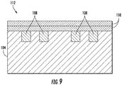
FIG. 9 is a cross-section side view of a fiber preform assembly in accordance with embodiments of the present disclosure. - Repeat use of reference characters in the present specification and drawings is intended to represent the same or analogous features or elements of the present technology.
- Reference will now be made in detail to present embodiments of the technology, one or more examples of which are illustrated in the accompanying drawings. The detailed description uses numerical and letter designations to refer to features in the drawings. Like or similar designations in the drawings and description have been used to refer to like or similar parts of the technology. As used herein, the terms "first", "second", and "third" may be used interchangeably to distinguish one component from another and are not intended to signify location or importance of the individual components.
- Each example is provided by way of explanation of the technology, not limitation of the technology. In fact, it will be apparent to those skilled in the art that modifications and variations can be made in the present technology without departing from the scope or spirit thereof. For instance, features illustrated or described as part of one embodiment may be used on another embodiment to yield a still further embodiment. Thus, it is intended that the present technology covers such modifications and variations as come within the scope of the appended claims and their equivalents.
- Referring now to the drawings,
FIG. 1 is a schematic view of an exemplarygas turbine engine 10. As shown, thegas turbine engine 10 generally includes acompressor section 12, acombustion section 14, and aturbine section 16. Thecompressor section 12 includes acompressor 18 having one or more rows ofcompressor vanes 20 and one or more rows ofcompressor rotor blades 22. Thecombustion section 14 includes one ormore combustors 24. Theturbine section 16 includes aturbine 26 having one or more rows ofturbine nozzles 28 and one or more rows ofturbine rotor blades 30. Thegas turbine engine 10 also includes ashaft 32 extending along anaxial centerline 34 of thegas turbine engine 10 that couples thecompressor 18 and theturbine 26. Theshaft 32 may be a single shaft or a plurality of shaft segments coupled together. - During operation, the
gas turbine engine 10 produces mechanical rotational energy, which may be used to produce electricity. More specifically,air 36 enters aninlet 38 of thegas turbine engine 10 and flows into thecompressor 18. Thecompressor vanes 20 direct theair 36 onto thecompressor rotor blades 22, which progressively compress theair 36 to providecompressed air 40 to each of thecombustors 24. Thecompressed air 40 mixes with a fuel, and the resulting fuel-air mixture burns within thecombustors 24 to produce high temperature and highpressure combustion gases 42. From thecombustors 24, thecombustion gases 42 flow into theturbine 26. The turbine nozzles 28 direct thecombustion gases 42 onto theturbine rotor blades 30, which extract kinetic and/or thermal energy from thecombustion gases 42. This energy extraction rotates theshaft 32, thereby creating mechanical rotational energy for powering thecompressor 18 and/or producing electricity. -
FIG. 2 illustrates acomposite component 100, which may be incorporated into thegas turbine engine 10. For example, thecomposite component 100 may be one of theturbine nozzles 28 or one of theturbine rotor blades 30. Thecomposite component 100 may also be any other component of thegas turbine engine 10, such as a combustor liner, a combustion flow sleeve, a turbine shroud block, or a turbine nozzle diaphragm. Furthermore, thecomposite component 100 may be incorporated into other types of turbomachines, such as a turbofan. In fact, thecomposite component 100 may be incorporated into any suitable machine or apparatus and/or have any suitable application. - The
composite component 100 may define one ormore passages 102 therein. A cooling fluid, such as bleed air from the compressor 18 (FIG. 1 ), may flow through thepassages 102, thereby cooling thecomposite component 100. In the embodiment shown inFIG. 2 , thecomposite component 100 defines onepassage 102 extending therethrough. In alternate embodiments, however, thecomposite component 100 may define two, three, ormore passages 102 extending therethrough. Thepassage 102 may have a curved path through thecomponent 100 as shown inFIG. 2 . Furthermore, thepassages 102 may also have any suitable cross-sectional shapes (e.g., circular, rectangular, etc.) and/or any suitable configuration. -
FIG. 3 illustrates acomposite component 101, which may be incorporated into thegas turbine engine 10. Like thecomposite component 100, thecomposite component 101 may be any component of thegas turbine engine 10 or any other suitable machine or apparatus. Thecomposite component 101 may define one ormore passages 103 therein. In the embodiment shown inFIG. 3 , thecomposite component 101 defines threepassages 103 extending therethrough. In alternate embodiments, however, thecomposite component 101 may define one, two, four, ormore passages 103 extending therethrough. Unlike thepassage 102 defined by thecomposite component 100, thepassages 103 are linear. Although, thepassages 103 may have any suitable configuration. - In some embodiments, the
composite components composite components -
FIG. 4 is a flow chart illustrating amethod 200 for forming a cooling passage defined by a composite component in accordance with embodiments of the present disclosure.Method 200 will be described below in the context of forming thecooling passage 102 in thecomposite component 100. However, the various steps ofmethod 200 may be used to form the cooling passage(s) 103 in thecomposite component 101. - Referring now to
FIGS. 3-5 , afiber preform 104 is formed instep 202 of themethod 200. Thefiber preform 104 is a precursor to and forms a portion of thecomposite component 100. In this respect, thefiber preform 104 is formed from one or more fibers. In embodiments where thecomposite component 100 is a CMC material, the fibers may be ceramic fibers, such as silicon carbide fibers. In an exemplary embodiment ofstep 202, the fibers may be coated with a coating via chemical vapor deposition. The fibers may then be drawn through a slurry, such as a ceramic slurry, and wet wound onto a drum. Once wet wound, the fibers may be formed into various plies, such as unidirectional tape plies and/or cloth plies (weaves). The plies may then be laid up onto a mold, mandrel, or other lay-up device in the desired shape of thecomposite component 100 to form thefiber preform 104. For example, the lay-up process may include stacking or layering multiple plies to form thefiber preform 104. In alternate embodiments, however, the fibers may be impregnated with the slurry after formation of thefiber preform 104. Some embodiments ofmethod 200 may not includestep 202. - In
step 204, acavity 106 is formed in thefiber preform 104. In particular, thecavity 106 may be formed by removing a portion of thefiber preform 104. In this respect, thecavity 106 may be formed using any suitable material removal method, technique, and/or process. For example, thecavity 106 may be formed using a mechanical cutter, electrical discharge machining (EDM), or laser machining. In alternate embodiments, however, thecavity 104 may be formed by cutting the individual plies before lay-up thereof duringstep 202. -
FIGS. 4 and5 illustrate thefiber preform 104 upon completion ofstep 204. Thecavity 104 forms at least a portion of thepassage 102 defined by thecomposite component 100. As such, thecavity 106 may have a similar form (e.g., shape, size, etc.) as at least a portion of thepassage 102. In the embodiment shown, thecavity 106 is open at the top thereof. In this respect, additional fiber plies may be placed onto thefiber preform 104 to completely define thepassage 102 as will be discussed in greater detail below. In alternate embodiments, however, thecavity 106 may be drilled (e.g., via EDM, drilling, milling, or grinding) or otherwise formed such that thefiber preform 104 entirely defines thepassage 102. In embodiments where thecomposite component 100 defines a plurality ofpassages 102,step 204 may include forming a plurality ofcavities 106. - In
step 206, acore 108 is inserted into thecavity 106 defined by thefiber preform 104. For example, in some embodiments, thecavity 106 may be filled with a slurry to form thecore 108. The slurry may be a ceramic slurry, such as a water-dissolvable ceramic slurry, or any other suitable slurry. In alternate embodiments, thecore 108 may be formed as a solid component and then placed in thecavity 106. In such embodiments, a mold, such as a plastic mold, having a mold cavity corresponding to the desired shape of thecore 108 may be formed. In particular, the mold may be formed via a suitable additive manufacturing process, such as three-dimensional printing. The mold cavity may then be filled with a slurry. The mold and slurry are heated in a furnace to burn off the mold and cure and sinter the slurry, thereby forming thecore 108. In further embodiments, however, thecore 108 may be formed using any suitable process (e.g., slip casting, hot isostatic pressing, or sintering). -
FIGS. 6 and 7 illustrate thefiber preform 104 upon completion ofstep 206. As shown, thecavity 106 defined by thefiber preform 104 is filled with the core 108 (e.g., the water-dissolvable ceramic slurry). In this respect, thecore 108 may conform to the shape, size, and configuration of thecavity 106. As will be discussed in greater detail below, thecore 108 prevents thecavity 106 and theresultant passage 102 from collapsing or filling with material during thermal processing and densification. - In
step 208, one or more fiber plies 110 are placed on thefiber preform 104. In particular, the fiber plies 110 may be stacked or layered on thefiber preform 104. In this respect, thefiber preform 104, thecore 108, and the fiber plies 110 collectively form afiber preform assembly 112 having the same shape, size, and configuration of thecomposite component 100. In some embodiments, multiple fiber preforms 102 may be laid up together to form thefiber preform assembly 112. The fiber plies 110 are generally formed as tapes, weaves, or cloths from one or more fibers. The fibers used to form the fiber plies 110 may be the same type (e.g., ceramic fibers, such as silicon carbide fibers) as the fibers used to form thefiber preform 104. - As shown in
FIG. 8 , the fiber plies 110 may be positioned over thecore 108. In this respect, the fiber plies 110 define the portion (i.e., the top) of thepassage 102 not defined by thefiber preform 104. In embodiments where thefiber preform 104 entirely defines thepassage 102, the fiber plies 110 may be laid elsewhere on thefiber preform 104. Furthermore, step 208 may be optional if thefiber preform 104 entirely defines thepassage 102core 108. In such instances, thefiber preform 104 may define the entire shape of thecomposite component 100. - In
step 210, thefiber preform assembly 112 is thermally processed. For example, in some embodiments, thermal processing may include autoclave processing followed by a burn-out cycle. More specifically, upon completion ofstep 208, thefiber preform assembly 112 may be placed in an autoclave and compacted or debulked at elevated temperature and/or pressure. The autoclave processing may also begin curing thefiber preform assembly 112. After the autoclave processing, thefiber preform assembly 112 is in a green state. Thefiber preform assembly 112 may then undergo a burn-out cycle (pyrolysis). During burn-out, thefiber preform assembly 112 is placed in a furnace and heated in an inert atmosphere or under a vacuum. This melts, sublimates, and/or converts the various binders, plasticizers, dispersants, solvents, and other processing materials in thefiber preform assembly 112. During burn-out, thefiber preform assembly 112 may be positioned to allow the melted or gaseous reaction products to exit out of thefiber preform assembly 112, thereby removing these reaction products from thefiber preform assembly 112. Various tooling or powder beds may support thefiber preform assembly 112 to allow proper breathing. As mentioned above, thecore 108 prevents thepassage 102 from collapsing during thermal processing (e.g., during autoclave consolidation or pyrolysis). In alternate embodiments, the thermal processing of thefiber preform assembly 112 may include other thermal processing operations in addition to or in lieu of the autoclave processing and burn-out cycle. Upon the completion ofstep 210, thefiber preform assembly 112 is highly porous. In particular, thefiber preform assembly 112 is typically a network of carbon, particulates, and ceramic fibers. - In
step 212, the fiber preform assembly is densified. For example, thefiber preform assembly 112 may be densified via melt infiltration. More specifically, thefiber preform assembly 112 may be placed in a vacuum furnace and heated to temperatures above the melting point or eutectic temperature of the infiltrant (typically above 1400° C). An infiltrant, such as molten metal or metalloid (e.g., molten silicon), infiltrates thepreform assembly 112, thereby filling the porosity created in thefiber preform assembly 112 as a result of the thermal processing ofstep 210. The infiltrant then reacts with components of the fiber preform assembly 112 (e.g., carbon introduced by drawing the fibers through the slurry in step 202) to form the matrix (e.g., silicon carbide) of thecomposite component 100. As indicated above, thecore 108 prevents thepassage 102 from filling with infiltrant during densification. Alternately, thefiber preform assembly 112 may be densified using Silcomp, chemical vapor infiltration, polymer infiltration and pyrolysis, oxide/oxide processes, molten metal submersion, vacuum hot pressing, or any other suitable densification process. Upon completion ofstep 112, thefiber preform assembly 112 is densified and the matrix is transformed into a ceramic, thereby forming the finishedcomposite component 100. - In
step 214, thecore 108 is removed from thecomposite component 100. Thecore 108 may be removed using any suitable method, technique, and/or process. If the geometry permits (e.g., thecomposite component 101 shown inFIG. 3 ), thecore 104 may simply be removed mechanically (e.g., removed by hand, mechanical shaking, or via a mechanical tool). Thecore 108 may also be removed by heating and/or chemical treatment. For example, thecomposite component 100 may undergo heat treatment, vacuum heat treatment, inert gas treatment, acid treatment, base treatment, or treatment with another suitable solvent. In this respect, thecore 104 may be removed via melting, dissolution, sublimation, evaporation, or the like. For example, if thecore 108 is formed of a water-dissolvable ceramic material, water may be used to dissolve thecore 108. Nevertheless, thecore 108 may be removed via any suitable technique. Step 214 may be performed aftersteps core 108 may be removed from thecomposite component 100 after thermal processing and densification. Furthermore, in some embodiments, the entirety of thecore 108 may be removed duringstep 214 and after completion ofsteps - After removal of the
core 108, thecomposite component 100 may optionally be finished instep 216. Finishing thecomposite component 100 may include machining and/or applying an environmental barrier coating. Other processes or steps also may be performed to finish thecomposite component 100 and prepare thecomposite component 100 for use in thegas turbine engine 10. - As discussed in greater detail above, the
method 200 disclosed herein includes positioning thecore 108 within each of thepassages composite component cores 108 prevent the fiber plies 110 from sagging or collapsing into thepassages core 108 is not used if the width of thepassage core 108 also prevents infiltrant from entering thepassages passages method 200. That is, thepassages passages composite component component -
Method 200 also provides other advantages. For example,method 200 permits the use of matrix plies in lieu of fiber plies 110. Furthermore,method 200 allows the fibers in the fiber plies 110 to be oriented in the primary stress direction of thecomposite component - This written description uses examples to disclose the technology, including the best mode, and also to enable any person skilled in the art to practice the technology, including making and using any devices or systems and performing any incorporated methods. The patentable scope of the technology is defined by the claims, and may include other examples that occur to those skilled in the art. Such other examples are intended to be within the scope of the claims if they include structural elements that do not differ from the literal language of the claims, or if they include equivalent structural elements with insubstantial differences from the literal language of the claims.
- Various aspects and embodiments of the present invention are defined by the following clauses:
- 1. A method for forming a passage in a composite component, the method comprising:
- forming a cavity in a fiber preform, the cavity forming a portion of the passage;
- inserting a core into the cavity;
- placing one or more fiber plies onto the fiber preform to form a fiber preform assembly;
- thermally processing the fiber preform assembly;
- densifying the fiber preform assembly to form the composite component; and
- removing the core from the composite component.
- 2. The method of clause 1, further comprising:
forming the fiber preform. - 3. The method of clause 1, wherein forming the cavity comprises removing material from the fiber preform.
- 4. The method of clause 1, wherein inserting the core comprises filling the cavity with a slurry.
- 5. The method of clause 1, further comprising:
- forming a mold for the core, the mold defining a mold cavity;
- filling the mold cavity with a slurry; and
- heating the mold to cure and sinter the slurry to form the core.
- 6. The method of clause 1, wherein thermally processing the fiber preform assembly comprises autoclave processing the fiber preform assembly.
- 7. The method of clause 1, wherein thermally processing the fiber preform assembly comprises burning-out the fiber preform assembly.
- 8. The method of clause 1, wherein densifying the fiber preform assembly comprises melt infiltrating the fiber preform assembly with an infiltrant.
- 9. The method of clause 1, wherein the infiltrant is formed from a metal or metalloid.
- 10. The method of clause 1, wherein removing the core comprises dissolving the core with water.
- 11. The method of clause 1, wherein removing the core comprises removing an entirety of the core.
- 12. The method of clause 1, wherein the fiber preform comprises a plurality of ceramic fibers.
- 13. The method of clause 1, wherein the core is formed from a ceramic material.
- 14. The method of clause 1, wherein the fiber preform has the same shape as the composite component.
- 15. A method for forming a passage in a ceramic matrix composite component, the method comprising:
- forming a fiber preform comprising a plurality of ceramic fibers;
- forming a cavity in the fiber preform, the cavity forming a portion of the passage;
- inserting a core into the cavity;
- placing one or more ceramic fiber plies onto the fiber preform to form a fiber preform assembly;
- thermally processing the fiber preform assembly;
- densifying the fiber preform assembly to form the ceramic matrix composite component; and
- removing the core from the ceramic matrix composite component.
- 16. The method of clause 15, wherein inserting the core comprises filling the cavity with a slurry.
- 17. The method of clause 15, further comprising:
- forming a mold for the core, the mold defining a mold cavity;
- filling the mold cavity with a slurry; and
- heating the mold to cure and sinter the slurry to form the core.
- 18. The method of clause 15, wherein thermally processing the fiber preform assembly comprises autoclave processing the fiber preform assembly and burning-out the fiber preform assembly, and wherein densifying the fiber preform assembly comprises melt infiltrating the fiber preform assembly with an infiltrant.
- 19. The method of clause 15, wherein removing the core comprises dissolving the core with water.
- 20. The method of clause 15, wherein removing the core comprises removing an entirety of the core.
Claims (15)
- A method (200) for forming a passage (102, 103) in a composite component (100, 101), the method (200) comprising:forming (204) a cavity (106) in a fiber preform (104), the cavity (106) forming a portion of the passage (102, 103);inserting (206) a core (108) into the cavity (106);placing (208) one or more fiber plies (110) onto the fiber preform (104) to form a fiber preform assembly (112);thermally processing (210) the fiber preform assembly (112);densifying (212) the fiber preform assembly (112) to form the composite component (100, 101); andremoving (214) the core (108) from the composite component (100, 101).
- The method (200) of claim 1, further comprising:
forming (202) the fiber preform (104). - The method (200) of claim 1 or 2, wherein forming (202) the cavity (106) comprises removing material from the fiber preform (104).
- The method (200) of any one of claims 1 to 3, wherein inserting (206) the core (108) comprises filling the cavity (106) with a slurry.
- The method (200) of any one of claims 1 to 4, further comprising:forming a mold for the core (108), the mold defining a mold cavity (106) ;filling the mold cavity (106) with a slurry; andheating the mold to cure and sinter the slurry to form the core (108).
- The method (200) of any one of claims 1 to 5, wherein thermally processing (210) the fiber preform assembly (112) comprises autoclave processing the fiber preform assembly (112).
- The method (200) of any one of claims 1 to 6, wherein thermally processing (210) the fiber preform assembly (112) comprises burning-out the fiber preform assembly (112).
- The method (200) of any one of claims 1 to 7, wherein densifying (212) the fiber preform assembly (112) comprises melt infiltrating the fiber preform assembly (112) with an infiltrant.
- The method (200) of claim 8, wherein the infiltrant is formed from a metal or metalloid.
- The method (200) of any one of claims 1 to 9, wherein removing (214) the core (108) comprises dissolving the core (108) with water.
- The method (200) of any one of claims 1 to 10, wherein removing (214) the core (108) comprises removing an entirety of the core (108).
- The method (200) of any one of claims 1 to 11, wherein the fiber preform (104) comprises a plurality of ceramic fibers.
- The method (200) of any one of claims 1 to 12, wherein the core (108) is formed from a ceramic material.
- The method (200) of any one of claims 1 to 13, wherein the fiber preform (104) has the same shape as the composite component (100, 101).
- A method (200) for forming a passage (102, 103) in a ceramic matrix composite component (100, 101), the method (200) comprising:forming (202) a fiber preform (104) comprising a plurality of ceramic fibers;forming (204) a cavity (106) in the fiber preform (104), the cavity (106) forming a portion of the passage (102, 103);inserting (206) a core (108) into the cavity (106);placing (208) one or more ceramic fiber plies (110) onto the fiber preform (104) to form a fiber preform assembly (112);thermally processing (210) the fiber preform assembly (112);densifying (212) the fiber preform assembly (112) to form the ceramic matrix composite component (100, 101); andremoving (214) the core (108) from the ceramic matrix composite component (100, 101).
Applications Claiming Priority (1)
| Application Number | Priority Date | Filing Date | Title |
|---|---|---|---|
| US15/465,726 US10562210B2 (en) | 2017-03-22 | 2017-03-22 | Method for forming passages in composite components |
Publications (2)
| Publication Number | Publication Date |
|---|---|
| EP3378846A1 true EP3378846A1 (en) | 2018-09-26 |
| EP3378846B1 EP3378846B1 (en) | 2023-04-26 |
Family
ID=61628142
Family Applications (1)
| Application Number | Title | Priority Date | Filing Date |
|---|---|---|---|
| EP18161348.0A Active EP3378846B1 (en) | 2017-03-22 | 2018-03-13 | Method for forming passages in composite components |
Country Status (3)
| Country | Link |
|---|---|
| US (1) | US10562210B2 (en) |
| EP (1) | EP3378846B1 (en) |
| JP (1) | JP7086660B2 (en) |
Cited By (1)
| Publication number | Priority date | Publication date | Assignee | Title |
|---|---|---|---|---|
| EP3950288A1 (en) * | 2020-07-31 | 2022-02-09 | General Electric Company | Method for repairing composite components using a plug |
Families Citing this family (6)
| Publication number | Priority date | Publication date | Assignee | Title |
|---|---|---|---|---|
| US9657580B1 (en) * | 2016-03-07 | 2017-05-23 | General Electric Company | Brazing tape and method of forming microchannels in a thermal barrier coating |
| US11578609B2 (en) | 2019-02-08 | 2023-02-14 | Raytheon Technologies Corporation | CMC component with integral cooling channels and method of manufacture |
| US11643948B2 (en) * | 2019-02-08 | 2023-05-09 | Raytheon Technologies Corporation | Internal cooling circuits for CMC and method of manufacture |
| US11384028B2 (en) * | 2019-05-03 | 2022-07-12 | Raytheon Technologies Corporation | Internal cooling circuits for CMC and method of manufacture |
| US11680488B2 (en) * | 2019-12-20 | 2023-06-20 | General Electric Company | Ceramic matrix composite component including cooling channels and method of producing |
| US20250137375A1 (en) * | 2023-10-27 | 2025-05-01 | Rtx Corporation | CMC Airfoil with Closed-Circuit Cooling Passage in Platform |
Citations (4)
| Publication number | Priority date | Publication date | Assignee | Title |
|---|---|---|---|---|
| US20030059577A1 (en) * | 2001-09-24 | 2003-03-27 | Siemens Westinghouse Power Corporation | Ceramic matrix composite structure having integral cooling passages and method of manufacture |
| US20030175453A1 (en) * | 2001-01-25 | 2003-09-18 | Steffier Wayne S. | Actively-cooled fiber-reinforced ceramic matrix composite rocket propulsion thrust chamber and method of producing the same |
| US20080115887A1 (en) * | 2006-11-22 | 2008-05-22 | Airbus Uk Limited | Method for forming a feature in a piece of composite material |
| EP2657210A1 (en) * | 2012-04-27 | 2013-10-30 | General Electric Company | Method of producing an internal cavity in a ceramic matrix composite |
Family Cites Families (18)
| Publication number | Priority date | Publication date | Assignee | Title |
|---|---|---|---|---|
| US3518338A (en) * | 1964-06-08 | 1970-06-30 | William C Tambussi | Molding process |
| JPH0472003A (en) * | 1990-07-10 | 1992-03-06 | Daido Steel Co Ltd | Manufacturing method of sintered body |
| US6627019B2 (en) | 2000-12-18 | 2003-09-30 | David C. Jarmon | Process for making ceramic matrix composite parts with cooling channels |
| FR2852003B1 (en) | 2003-03-04 | 2005-05-27 | Snecma Propulsion Solide | PROCESS FOR PRODUCING A MULTIPERFORATED PART IN CERAMIC MATRIX COMPOSITE MATERIAL |
| US6984277B2 (en) | 2003-07-31 | 2006-01-10 | Siemens Westinghouse Power Corporation | Bond enhancement for thermally insulated ceramic matrix composite materials |
| US7153464B2 (en) | 2003-12-01 | 2006-12-26 | General Electric Company | Method of making porous ceramic matrix composites |
| US8167573B2 (en) | 2008-09-19 | 2012-05-01 | Siemens Energy, Inc. | Gas turbine airfoil |
| FR2949091B1 (en) | 2009-08-17 | 2015-06-26 | Snecma | METHOD FOR PRODUCING A HOLLOW MONOBLOCK HOLLOW DISC |
| US8876481B2 (en) | 2011-01-05 | 2014-11-04 | General Electric Company | Turbine airfoil component assembly for use in a gas turbine engine and methods for fabricating same |
| US10450235B2 (en) | 2012-04-27 | 2019-10-22 | General Electric Company | Method of producing an internal cavity in a ceramic matrix composite and mandrel therefor |
| US9751807B2 (en) | 2012-08-16 | 2017-09-05 | General Electric Company | Consumable core for manufacture of composite articles and related method |
| CN103061827B (en) | 2013-01-06 | 2015-05-06 | 北京航空航天大学 | Hybrid nozzle guide vane made of ceramic matrix composite materials |
| CA2897058A1 (en) | 2013-03-04 | 2014-10-02 | Rolls-Royce North American Technologies, Inc. | Method for making gas turbine engine ceramic matrix composite airfoil |
| US9328620B2 (en) | 2013-03-13 | 2016-05-03 | Rolls-Royce Corporation | Method for making gas turbine engine composite structure |
| US9709274B2 (en) | 2013-03-15 | 2017-07-18 | Rolls-Royce Plc | Auxetic structure with stress-relief features |
| US9726025B2 (en) | 2013-03-15 | 2017-08-08 | Rolls-Royce Corporation | Ceramic matrix composite |
| CA2911943A1 (en) | 2013-05-14 | 2015-02-05 | Nicholas Joseph Kray | Composite woven outlet guide vane |
| WO2014193565A1 (en) | 2013-05-29 | 2014-12-04 | General Electric Company | Method of forming a ceramic matrix composite component with cooling features |
-
2017
- 2017-03-22 US US15/465,726 patent/US10562210B2/en active Active
-
2018
- 2018-03-13 EP EP18161348.0A patent/EP3378846B1/en active Active
- 2018-03-20 JP JP2018052053A patent/JP7086660B2/en active Active
Patent Citations (4)
| Publication number | Priority date | Publication date | Assignee | Title |
|---|---|---|---|---|
| US20030175453A1 (en) * | 2001-01-25 | 2003-09-18 | Steffier Wayne S. | Actively-cooled fiber-reinforced ceramic matrix composite rocket propulsion thrust chamber and method of producing the same |
| US20030059577A1 (en) * | 2001-09-24 | 2003-03-27 | Siemens Westinghouse Power Corporation | Ceramic matrix composite structure having integral cooling passages and method of manufacture |
| US20080115887A1 (en) * | 2006-11-22 | 2008-05-22 | Airbus Uk Limited | Method for forming a feature in a piece of composite material |
| EP2657210A1 (en) * | 2012-04-27 | 2013-10-30 | General Electric Company | Method of producing an internal cavity in a ceramic matrix composite |
Cited By (1)
| Publication number | Priority date | Publication date | Assignee | Title |
|---|---|---|---|---|
| EP3950288A1 (en) * | 2020-07-31 | 2022-02-09 | General Electric Company | Method for repairing composite components using a plug |
Also Published As
| Publication number | Publication date |
|---|---|
| EP3378846B1 (en) | 2023-04-26 |
| US20180272568A1 (en) | 2018-09-27 |
| US10562210B2 (en) | 2020-02-18 |
| JP7086660B2 (en) | 2022-06-20 |
| JP2018165510A (en) | 2018-10-25 |
Similar Documents
| Publication | Publication Date | Title |
|---|---|---|
| EP3378846B1 (en) | Method for forming passages in composite components | |
| EP3004559B1 (en) | Method of forming a ceramic matrix composite component with cooling features | |
| US11441436B2 (en) | Flow path assemblies for gas turbine engines and assembly methods therefore | |
| US10260358B2 (en) | Ceramic matrix composite component and process of producing a ceramic matrix composite component | |
| JP6888933B2 (en) | Ceramic Matrix Composite Components and Methods for Manufacturing Ceramic Matrix Composite Components | |
| US11149575B2 (en) | Airfoil fluid curtain to mitigate or prevent flow path leakage | |
| CN113389600B (en) | Nozzle assembly with alternating guide vanes for a turbine engine | |
| CN115013077B (en) | Integrated flow path structure | |
| US20240117756A1 (en) | Cte matching hanger support for cmc structures | |
| CN110234845A (en) | Integrated flow path structure | |
| JP2017105698A5 (en) | ||
| CN110214250A (en) | Integrated flow path configurations | |
| CA3102096A1 (en) | Ceramic matrix composite component and method of producing a ceramic matrix composite component | |
| EP2774754B1 (en) | Ceramic matrix composite component forming method | |
| US20260139626A1 (en) | Cmc component with dormant cooling holes |
Legal Events
| Date | Code | Title | Description |
|---|---|---|---|
| PUAI | Public reference made under article 153(3) epc to a published international application that has entered the european phase |
Free format text: ORIGINAL CODE: 0009012 |
|
| STAA | Information on the status of an ep patent application or granted ep patent |
Free format text: STATUS: THE APPLICATION HAS BEEN PUBLISHED |
|
| AK | Designated contracting states |
Kind code of ref document: A1 Designated state(s): AL AT BE BG CH CY CZ DE DK EE ES FI FR GB GR HR HU IE IS IT LI LT LU LV MC MK MT NL NO PL PT RO RS SE SI SK SM TR |
|
| AX | Request for extension of the european patent |
Extension state: BA ME |
|
| STAA | Information on the status of an ep patent application or granted ep patent |
Free format text: STATUS: REQUEST FOR EXAMINATION WAS MADE |
|
| 17P | Request for examination filed |
Effective date: 20190311 |
|
| RBV | Designated contracting states (corrected) |
Designated state(s): AL AT BE BG CH CY CZ DE DK EE ES FI FR GB GR HR HU IE IS IT LI LT LU LV MC MK MT NL NO PL PT RO RS SE SI SK SM TR |
|
| STAA | Information on the status of an ep patent application or granted ep patent |
Free format text: STATUS: EXAMINATION IS IN PROGRESS |
|
| 17Q | First examination report despatched |
Effective date: 20190924 |
|
| GRAP | Despatch of communication of intention to grant a patent |
Free format text: ORIGINAL CODE: EPIDOSNIGR1 |
|
| STAA | Information on the status of an ep patent application or granted ep patent |
Free format text: STATUS: GRANT OF PATENT IS INTENDED |
|
| INTG | Intention to grant announced |
Effective date: 20230110 |
|
| GRAS | Grant fee paid |
Free format text: ORIGINAL CODE: EPIDOSNIGR3 |
|
| GRAA | (expected) grant |
Free format text: ORIGINAL CODE: 0009210 |
|
| STAA | Information on the status of an ep patent application or granted ep patent |
Free format text: STATUS: THE PATENT HAS BEEN GRANTED |
|
| AK | Designated contracting states |
Kind code of ref document: B1 Designated state(s): AL AT BE BG CH CY CZ DE DK EE ES FI FR GB GR HR HU IE IS IT LI LT LU LV MC MK MT NL NO PL PT RO RS SE SI SK SM TR |
|
| REG | Reference to a national code |
Ref country code: GB Ref legal event code: FG4D |
|
| REG | Reference to a national code |
Ref country code: CH Ref legal event code: EP |
|
| REG | Reference to a national code |
Ref country code: DE Ref legal event code: R096 Ref document number: 602018048807 Country of ref document: DE |
|
| REG | Reference to a national code |
Ref country code: AT Ref legal event code: REF Ref document number: 1562733 Country of ref document: AT Kind code of ref document: T Effective date: 20230515 |
|
| REG | Reference to a national code |
Ref country code: IE Ref legal event code: FG4D |
|
| REG | Reference to a national code |
Ref country code: LT Ref legal event code: MG9D |
|
| REG | Reference to a national code |
Ref country code: NL Ref legal event code: MP Effective date: 20230426 |
|
| REG | Reference to a national code |
Ref country code: AT Ref legal event code: MK05 Ref document number: 1562733 Country of ref document: AT Kind code of ref document: T Effective date: 20230426 |
|
| PG25 | Lapsed in a contracting state [announced via postgrant information from national office to epo] |
Ref country code: NL Free format text: LAPSE BECAUSE OF FAILURE TO SUBMIT A TRANSLATION OF THE DESCRIPTION OR TO PAY THE FEE WITHIN THE PRESCRIBED TIME-LIMIT Effective date: 20230426 |
|
| PG25 | Lapsed in a contracting state [announced via postgrant information from national office to epo] |
Ref country code: SE Free format text: LAPSE BECAUSE OF FAILURE TO SUBMIT A TRANSLATION OF THE DESCRIPTION OR TO PAY THE FEE WITHIN THE PRESCRIBED TIME-LIMIT Effective date: 20230426 Ref country code: PT Free format text: LAPSE BECAUSE OF FAILURE TO SUBMIT A TRANSLATION OF THE DESCRIPTION OR TO PAY THE FEE WITHIN THE PRESCRIBED TIME-LIMIT Effective date: 20230828 Ref country code: NO Free format text: LAPSE BECAUSE OF FAILURE TO SUBMIT A TRANSLATION OF THE DESCRIPTION OR TO PAY THE FEE WITHIN THE PRESCRIBED TIME-LIMIT Effective date: 20230726 Ref country code: ES Free format text: LAPSE BECAUSE OF FAILURE TO SUBMIT A TRANSLATION OF THE DESCRIPTION OR TO PAY THE FEE WITHIN THE PRESCRIBED TIME-LIMIT Effective date: 20230426 Ref country code: AT Free format text: LAPSE BECAUSE OF FAILURE TO SUBMIT A TRANSLATION OF THE DESCRIPTION OR TO PAY THE FEE WITHIN THE PRESCRIBED TIME-LIMIT Effective date: 20230426 |
|
| REG | Reference to a national code |
Ref country code: DE Ref legal event code: R081 Ref document number: 602018048807 Country of ref document: DE Owner name: GENERAL ELECTRIC TECHNOLOGY GMBH, CH Free format text: FORMER OWNER: GENERAL ELECTRIC COMPANY, SCHENECTADY, NY, US |
|
| PG25 | Lapsed in a contracting state [announced via postgrant information from national office to epo] |
Ref country code: RS Free format text: LAPSE BECAUSE OF FAILURE TO SUBMIT A TRANSLATION OF THE DESCRIPTION OR TO PAY THE FEE WITHIN THE PRESCRIBED TIME-LIMIT Effective date: 20230426 Ref country code: PL Free format text: LAPSE BECAUSE OF FAILURE TO SUBMIT A TRANSLATION OF THE DESCRIPTION OR TO PAY THE FEE WITHIN THE PRESCRIBED TIME-LIMIT Effective date: 20230426 Ref country code: LV Free format text: LAPSE BECAUSE OF FAILURE TO SUBMIT A TRANSLATION OF THE DESCRIPTION OR TO PAY THE FEE WITHIN THE PRESCRIBED TIME-LIMIT Effective date: 20230426 Ref country code: LT Free format text: LAPSE BECAUSE OF FAILURE TO SUBMIT A TRANSLATION OF THE DESCRIPTION OR TO PAY THE FEE WITHIN THE PRESCRIBED TIME-LIMIT Effective date: 20230426 Ref country code: IS Free format text: LAPSE BECAUSE OF FAILURE TO SUBMIT A TRANSLATION OF THE DESCRIPTION OR TO PAY THE FEE WITHIN THE PRESCRIBED TIME-LIMIT Effective date: 20230826 Ref country code: HR Free format text: LAPSE BECAUSE OF FAILURE TO SUBMIT A TRANSLATION OF THE DESCRIPTION OR TO PAY THE FEE WITHIN THE PRESCRIBED TIME-LIMIT Effective date: 20230426 Ref country code: GR Free format text: LAPSE BECAUSE OF FAILURE TO SUBMIT A TRANSLATION OF THE DESCRIPTION OR TO PAY THE FEE WITHIN THE PRESCRIBED TIME-LIMIT Effective date: 20230727 |
|
| RAP2 | Party data changed (patent owner data changed or rights of a patent transferred) |
Owner name: GENERAL ELECTRIC TECHNOLOGY GMBH |
|
| PG25 | Lapsed in a contracting state [announced via postgrant information from national office to epo] |
Ref country code: FI Free format text: LAPSE BECAUSE OF FAILURE TO SUBMIT A TRANSLATION OF THE DESCRIPTION OR TO PAY THE FEE WITHIN THE PRESCRIBED TIME-LIMIT Effective date: 20230426 |
|
| PG25 | Lapsed in a contracting state [announced via postgrant information from national office to epo] |
Ref country code: SK Free format text: LAPSE BECAUSE OF FAILURE TO SUBMIT A TRANSLATION OF THE DESCRIPTION OR TO PAY THE FEE WITHIN THE PRESCRIBED TIME-LIMIT Effective date: 20230426 |
|
| REG | Reference to a national code |
Ref country code: DE Ref legal event code: R097 Ref document number: 602018048807 Country of ref document: DE |
|
| PG25 | Lapsed in a contracting state [announced via postgrant information from national office to epo] |
Ref country code: SM Free format text: LAPSE BECAUSE OF FAILURE TO SUBMIT A TRANSLATION OF THE DESCRIPTION OR TO PAY THE FEE WITHIN THE PRESCRIBED TIME-LIMIT Effective date: 20230426 Ref country code: SK Free format text: LAPSE BECAUSE OF FAILURE TO SUBMIT A TRANSLATION OF THE DESCRIPTION OR TO PAY THE FEE WITHIN THE PRESCRIBED TIME-LIMIT Effective date: 20230426 Ref country code: RO Free format text: LAPSE BECAUSE OF FAILURE TO SUBMIT A TRANSLATION OF THE DESCRIPTION OR TO PAY THE FEE WITHIN THE PRESCRIBED TIME-LIMIT Effective date: 20230426 Ref country code: EE Free format text: LAPSE BECAUSE OF FAILURE TO SUBMIT A TRANSLATION OF THE DESCRIPTION OR TO PAY THE FEE WITHIN THE PRESCRIBED TIME-LIMIT Effective date: 20230426 Ref country code: DK Free format text: LAPSE BECAUSE OF FAILURE TO SUBMIT A TRANSLATION OF THE DESCRIPTION OR TO PAY THE FEE WITHIN THE PRESCRIBED TIME-LIMIT Effective date: 20230426 Ref country code: CZ Free format text: LAPSE BECAUSE OF FAILURE TO SUBMIT A TRANSLATION OF THE DESCRIPTION OR TO PAY THE FEE WITHIN THE PRESCRIBED TIME-LIMIT Effective date: 20230426 |
|
| PLBE | No opposition filed within time limit |
Free format text: ORIGINAL CODE: 0009261 |
|
| STAA | Information on the status of an ep patent application or granted ep patent |
Free format text: STATUS: NO OPPOSITION FILED WITHIN TIME LIMIT |
|
| REG | Reference to a national code |
Ref country code: GB Ref legal event code: 732E Free format text: REGISTERED BETWEEN 20240222 AND 20240228 |
|
| 26N | No opposition filed |
Effective date: 20240129 |
|
| PG25 | Lapsed in a contracting state [announced via postgrant information from national office to epo] |
Ref country code: SI Free format text: LAPSE BECAUSE OF FAILURE TO SUBMIT A TRANSLATION OF THE DESCRIPTION OR TO PAY THE FEE WITHIN THE PRESCRIBED TIME-LIMIT Effective date: 20230426 |
|
| PG25 | Lapsed in a contracting state [announced via postgrant information from national office to epo] |
Ref country code: SI Free format text: LAPSE BECAUSE OF FAILURE TO SUBMIT A TRANSLATION OF THE DESCRIPTION OR TO PAY THE FEE WITHIN THE PRESCRIBED TIME-LIMIT Effective date: 20230426 Ref country code: IT Free format text: LAPSE BECAUSE OF FAILURE TO SUBMIT A TRANSLATION OF THE DESCRIPTION OR TO PAY THE FEE WITHIN THE PRESCRIBED TIME-LIMIT Effective date: 20230426 |
|
| REG | Reference to a national code |
Ref country code: CH Ref legal event code: PL |
|
| PG25 | Lapsed in a contracting state [announced via postgrant information from national office to epo] |
Ref country code: BG Free format text: LAPSE BECAUSE OF FAILURE TO SUBMIT A TRANSLATION OF THE DESCRIPTION OR TO PAY THE FEE WITHIN THE PRESCRIBED TIME-LIMIT Effective date: 20230426 |
|
| PG25 | Lapsed in a contracting state [announced via postgrant information from national office to epo] |
Ref country code: LU Free format text: LAPSE BECAUSE OF NON-PAYMENT OF DUE FEES Effective date: 20240313 |
|
| PG25 | Lapsed in a contracting state [announced via postgrant information from national office to epo] |
Ref country code: MC Free format text: LAPSE BECAUSE OF FAILURE TO SUBMIT A TRANSLATION OF THE DESCRIPTION OR TO PAY THE FEE WITHIN THE PRESCRIBED TIME-LIMIT Effective date: 20230426 |
|
| PG25 | Lapsed in a contracting state [announced via postgrant information from national office to epo] |
Ref country code: MC Free format text: LAPSE BECAUSE OF FAILURE TO SUBMIT A TRANSLATION OF THE DESCRIPTION OR TO PAY THE FEE WITHIN THE PRESCRIBED TIME-LIMIT Effective date: 20230426 Ref country code: LU Free format text: LAPSE BECAUSE OF NON-PAYMENT OF DUE FEES Effective date: 20240313 Ref country code: BG Free format text: LAPSE BECAUSE OF FAILURE TO SUBMIT A TRANSLATION OF THE DESCRIPTION OR TO PAY THE FEE WITHIN THE PRESCRIBED TIME-LIMIT Effective date: 20230426 |
|
| REG | Reference to a national code |
Ref country code: BE Ref legal event code: MM Effective date: 20240331 |
|
| PG25 | Lapsed in a contracting state [announced via postgrant information from national office to epo] |
Ref country code: BE Free format text: LAPSE BECAUSE OF NON-PAYMENT OF DUE FEES Effective date: 20240331 |
|
| PG25 | Lapsed in a contracting state [announced via postgrant information from national office to epo] |
Ref country code: IE Free format text: LAPSE BECAUSE OF NON-PAYMENT OF DUE FEES Effective date: 20240313 |
|
| PG25 | Lapsed in a contracting state [announced via postgrant information from national office to epo] |
Ref country code: IE Free format text: LAPSE BECAUSE OF NON-PAYMENT OF DUE FEES Effective date: 20240313 Ref country code: BE Free format text: LAPSE BECAUSE OF NON-PAYMENT OF DUE FEES Effective date: 20240331 Ref country code: CH Free format text: LAPSE BECAUSE OF NON-PAYMENT OF DUE FEES Effective date: 20240331 |
|
| PG25 | Lapsed in a contracting state [announced via postgrant information from national office to epo] |
Ref country code: CY Free format text: LAPSE BECAUSE OF FAILURE TO SUBMIT A TRANSLATION OF THE DESCRIPTION OR TO PAY THE FEE WITHIN THE PRESCRIBED TIME-LIMIT; INVALID AB INITIO Effective date: 20180313 |
|
| PG25 | Lapsed in a contracting state [announced via postgrant information from national office to epo] |
Ref country code: HU Free format text: LAPSE BECAUSE OF FAILURE TO SUBMIT A TRANSLATION OF THE DESCRIPTION OR TO PAY THE FEE WITHIN THE PRESCRIBED TIME-LIMIT; INVALID AB INITIO Effective date: 20180313 |
|
| PG25 | Lapsed in a contracting state [announced via postgrant information from national office to epo] |
Ref country code: TR Free format text: LAPSE BECAUSE OF FAILURE TO SUBMIT A TRANSLATION OF THE DESCRIPTION OR TO PAY THE FEE WITHIN THE PRESCRIBED TIME-LIMIT Effective date: 20230426 |
|
| PGFP | Annual fee paid to national office [announced via postgrant information from national office to epo] |
Ref country code: GB Payment date: 20260219 Year of fee payment: 9 |
|
| PGFP | Annual fee paid to national office [announced via postgrant information from national office to epo] |
Ref country code: DE Payment date: 20260219 Year of fee payment: 9 |
|
| PGFP | Annual fee paid to national office [announced via postgrant information from national office to epo] |
Ref country code: FR Payment date: 20260219 Year of fee payment: 9 |