EP3378829A1 - Tank with ventilation - Google Patents
Tank with ventilation Download PDFInfo
- Publication number
- EP3378829A1 EP3378829A1 EP18160677.3A EP18160677A EP3378829A1 EP 3378829 A1 EP3378829 A1 EP 3378829A1 EP 18160677 A EP18160677 A EP 18160677A EP 3378829 A1 EP3378829 A1 EP 3378829A1
- Authority
- EP
- European Patent Office
- Prior art keywords
- tank
- air inlet
- air
- outlet
- inlet device
- Prior art date
- Legal status (The legal status is an assumption and is not a legal conclusion. Google has not performed a legal analysis and makes no representation as to the accuracy of the status listed.)
- Granted
Links
- 238000009423 ventilation Methods 0.000 title 1
- 230000009969 flowable effect Effects 0.000 claims abstract description 18
- 238000000034 method Methods 0.000 claims description 6
- 230000007547 defect Effects 0.000 description 2
- 239000012530 fluid Substances 0.000 description 2
- 230000001105 regulatory effect Effects 0.000 description 2
- 238000007789 sealing Methods 0.000 description 2
- 239000000969 carrier Substances 0.000 description 1
- 230000001419 dependent effect Effects 0.000 description 1
- 239000007788 liquid Substances 0.000 description 1
- 239000000463 material Substances 0.000 description 1
- 239000002184 metal Substances 0.000 description 1
- 238000005086 pumping Methods 0.000 description 1
Images
Classifications
-
- B—PERFORMING OPERATIONS; TRANSPORTING
- B67—OPENING, CLOSING OR CLEANING BOTTLES, JARS OR SIMILAR CONTAINERS; LIQUID HANDLING
- B67D—DISPENSING, DELIVERING OR TRANSFERRING LIQUIDS, NOT OTHERWISE PROVIDED FOR
- B67D1/00—Apparatus or devices for dispensing beverages on draught
- B67D1/0003—Apparatus or devices for dispensing beverages on draught the beverage being a single liquid
- B67D1/0004—Apparatus or devices for dispensing beverages on draught the beverage being a single liquid the beverage being stored in a container, e.g. bottle, cartridge, bag-in-box, bowl
-
- A—HUMAN NECESSITIES
- A01—AGRICULTURE; FORESTRY; ANIMAL HUSBANDRY; HUNTING; TRAPPING; FISHING
- A01M—CATCHING, TRAPPING OR SCARING OF ANIMALS; APPARATUS FOR THE DESTRUCTION OF NOXIOUS ANIMALS OR NOXIOUS PLANTS
- A01M7/00—Special adaptations or arrangements of liquid-spraying apparatus for purposes covered by this subclass
- A01M7/0082—Undercarriages, frames, mountings, couplings, tanks
- A01M7/0085—Tanks
-
- B—PERFORMING OPERATIONS; TRANSPORTING
- B67—OPENING, CLOSING OR CLEANING BOTTLES, JARS OR SIMILAR CONTAINERS; LIQUID HANDLING
- B67D—DISPENSING, DELIVERING OR TRANSFERRING LIQUIDS, NOT OTHERWISE PROVIDED FOR
- B67D1/00—Apparatus or devices for dispensing beverages on draught
- B67D1/04—Apparatus utilising compressed air or other gas acting directly or indirectly on beverages in storage containers
- B67D1/0462—Squeezing collapsible or flexible beverage containers, e.g. bag-in-box containers
-
- B—PERFORMING OPERATIONS; TRANSPORTING
- B67—OPENING, CLOSING OR CLEANING BOTTLES, JARS OR SIMILAR CONTAINERS; LIQUID HANDLING
- B67D—DISPENSING, DELIVERING OR TRANSFERRING LIQUIDS, NOT OTHERWISE PROVIDED FOR
- B67D3/00—Apparatus or devices for controlling flow of liquids under gravity from storage containers for dispensing purposes
- B67D3/0058—Details
- B67D3/0061—Details of liquid containers, e.g. filling, emptying, closing or opening means
-
- B—PERFORMING OPERATIONS; TRANSPORTING
- B67—OPENING, CLOSING OR CLEANING BOTTLES, JARS OR SIMILAR CONTAINERS; LIQUID HANDLING
- B67D—DISPENSING, DELIVERING OR TRANSFERRING LIQUIDS, NOT OTHERWISE PROVIDED FOR
- B67D7/00—Apparatus or devices for transferring liquids from bulk storage containers or reservoirs into vehicles or into portable containers, e.g. for retail sale purposes
- B67D7/02—Apparatus or devices for transferring liquids from bulk storage containers or reservoirs into vehicles or into portable containers, e.g. for retail sale purposes for transferring liquids other than fuel or lubricants
- B67D7/0238—Apparatus or devices for transferring liquids from bulk storage containers or reservoirs into vehicles or into portable containers, e.g. for retail sale purposes for transferring liquids other than fuel or lubricants utilising compressed air or other gas acting directly or indirectly on liquids in storage containers
- B67D7/0266—Apparatus or devices for transferring liquids from bulk storage containers or reservoirs into vehicles or into portable containers, e.g. for retail sale purposes for transferring liquids other than fuel or lubricants utilising compressed air or other gas acting directly or indirectly on liquids in storage containers by gas acting directly on the liquid
-
- B—PERFORMING OPERATIONS; TRANSPORTING
- B67—OPENING, CLOSING OR CLEANING BOTTLES, JARS OR SIMILAR CONTAINERS; LIQUID HANDLING
- B67D—DISPENSING, DELIVERING OR TRANSFERRING LIQUIDS, NOT OTHERWISE PROVIDED FOR
- B67D1/00—Apparatus or devices for dispensing beverages on draught
- B67D2001/0095—Constructional details
- B67D2001/0096—Means for pressurizing liquid
- B67D2001/0098—Means for pressurizing liquid using a gas
-
- B—PERFORMING OPERATIONS; TRANSPORTING
- B67—OPENING, CLOSING OR CLEANING BOTTLES, JARS OR SIMILAR CONTAINERS; LIQUID HANDLING
- B67D—DISPENSING, DELIVERING OR TRANSFERRING LIQUIDS, NOT OTHERWISE PROVIDED FOR
- B67D1/00—Apparatus or devices for dispensing beverages on draught
- B67D1/08—Details
- B67D1/0801—Details of beverage containers, e.g. casks, kegs
- B67D2001/0812—Bottles, cartridges or similar containers
-
- B—PERFORMING OPERATIONS; TRANSPORTING
- B67—OPENING, CLOSING OR CLEANING BOTTLES, JARS OR SIMILAR CONTAINERS; LIQUID HANDLING
- B67D—DISPENSING, DELIVERING OR TRANSFERRING LIQUIDS, NOT OTHERWISE PROVIDED FOR
- B67D1/00—Apparatus or devices for dispensing beverages on draught
- B67D1/08—Details
- B67D1/0801—Details of beverage containers, e.g. casks, kegs
- B67D2001/0822—Pressurised rigid containers, e.g. kegs, figals
Definitions
- the air inlet device and / or the outlet valve are connected to the tank or connected to this, that they can be replaced at any time or completely removed.
- a defect it is possible to exchange the air intake device or the exhaust valve.
- a non-functioning tank e.g. to remove a tank damaged by an unwanted hole or crack, the air inlet device and / or the exhaust valve and to use at a new tank.
- the complete tank arrangement does not have to be disposed of.
- the present application is further directed to a method for filling a tank with a flowable medium and for removing the flowable medium from the tank, wherein the tank has an inlet and a drain through which the flowable medium can be introduced or discharged into the tank wherein a valve means on the drain can be manually transferred via a lever from an open position to a closed position and / or vice versa.
- the tank can be vented via an air inlet device with an air inlet through which air can be delivered to the tank.
Abstract
Tankanordnung (1) mit einem Tank (2) mit einem Zulauf um den Tank (2) mit einem fließfähigen Medium zu befüllen und einem Ablauf (10) um ein Medium aus dem Tank (2) zu entnehmen, wobei der Ablauf (10) eine Ventileinrichtung (4 a) aufweist, welche manuell über einen Hebel (18 a) von einer geöffneten Stellung in eine geschlossene Stellung und/ oder umgekehrt überführbar ist wobei der Tank (2) eine Lufteinlasseinrichtung (6) mit einem Lufteinlass (12) aufweist, über welche Luft in den Tank (2) gefördert werden kann, um den Tank (2) entlüften zu können, dadurch gekennzeichnet, dass an dem Lufteinlass (12) eine Luftleitung anschließbar ist um den Tank (2) über die Lufeinlasseinrichtung (6) Luft zuzuführen.Tank arrangement (1) with a tank (2) with an inlet to fill the tank (2) with a flowable medium and a drain (10) to remove a medium from the tank (2), the outlet (10) a Valve device (4 a), which is manually via a lever (18 a) from an open position to a closed position and / or vice versa transferable wherein the tank (2) has an air inlet device (6) with an air inlet (12) over which air can be conveyed into the tank (2) in order to vent the tank (2), characterized in that an air line can be connected to the air inlet (12) in order to supply air to the tank (2) via the air inlet device (6) ,
Description
Die vorliegende Erfindung betrifft eine Tankanordnung mit einer Lufteinlasseinrichtung, wodurch dem Innenraum eines Tanks Luft zugeführt werden kann. So kann der Tank entlüftet und der Volumenstrom des Abflusses gesteuert werden. Aus dem Stand der Technik sind solche Geräte/ Tanks bekannt. Üblicherweise arbeiten solche Tanks mit einem Auslassventil, aus welchem das in dem Tank befindliche fließfähige Medium ausgelassen werden kann und einem zweiten Auslassventil, über welches der innerhalb des Tanks entstandene Druck abgelassen werden kann. Ein wesentlicher Nachteil aus dem Stand der Technik ist, dass ein Tank nur im gefüllten Zustand entlüftet werden kann. Ein Nachteil der aus dem Stand der Technik bekannten Anordnungen besteht darin dass diese nur mit einer begrenzten Geschwindigkeit entleerbar sind.The present invention relates to a tank assembly with an air inlet device, whereby the interior of a tank air can be supplied. This allows the tank to be vented and the volume flow of the drain to be controlled. Such devices / tanks are known from the prior art. Usually, such tanks operate with an outlet valve, from which the flowable medium in the tank can be discharged, and a second outlet valve, via which the pressure arising within the tank can be vented. A major disadvantage of the prior art is that a tank can be vented only in the filled state. A disadvantage of the arrangements known from the prior art is that they can only be emptied at a limited speed.
Der vorliegenden Erfindung liegt die Aufgabe zugrunde, ein Entlüftungsprinzip aufzuzeigen, durch welches ein Tank entlüftet werden kann, wobei die Entlüftung auch möglich ist, wenn sich im Tank kein fließfähiges Medium befindet.The present invention has for its object to provide a vent principle by which a tank can be vented, the vent is also possible if there is no fluid medium in the tank.
Diese Aufgabe wird durch den unabhängigen Anspruch 1 gelöst. Vorteilhafte Ausgestaltungen der Erfindung sind Gegenstand der Unteransprüche.This object is solved by the
Eine erfindungsgemäße Tankanordnung weist einen Tank mit einem Zulauf, um dem Tank mit einem fließfähigen Medium zu befüllen und einen Ablauf, um ein Medium aus dem Tank zu entnehmen, auf, wobei der Ablauf eine Ventileinrichtung aufweist, welche manuell über einen Hebel von einer geöffneten Stellung in eine geschlossene Stellung und/ oder umgekehrt überführbar ist und wobei der Tank eine Lufteinlasseinrichtung mit einem Lufteinlass aufweist, über welche Luft in den Tank gefördert werden kann, umso den Tank entlüften zu können.A tank assembly according to the invention comprises a tank with a feed to fill the tank with a flowable medium and a drain to a medium from the tank the drain having a valve device which is manually convertible via a lever from an open position to a closed position and / or vice versa, and wherein the tank has an air inlet device with an air inlet via which air is conveyed into the tank can, so as to be able to vent the tank.
Erfindungsgemäß ist an dem Lufteinlass eine Luftleitung anschließbar, um den Tank über die Lufteinlasseinrichtung Luft zuführen zu können. Unter der Lufteinlasseinrichtung wird im Folgenden die gesamte Einrichtung verstanden, welche dem besagten Lufteinlass dient und welche etwa auch ein Ventil aufweisen kann. Unterdem Lufteinlass wird ein Element verstanden, welches unmittelbar dem Lufteinlass dient, wie etwa im einfachsten Fall eine Öffnung oder eine Leitung.According to the invention, an air line can be connected to the air inlet in order to be able to supply air to the tank via the air inlet device. In the text which follows, the air intake device is understood to mean the entire device which serves for the said air intake and which may also have a valve. The air inlet means an element which directly serves the air inlet, such as in the simplest case an opening or a pipe.
Bevorzugt handelt es sich bei dem Zulauf und dem Ablauf um die gleiche Einrichtung. So wäre es zum Beispielspiel denkbar, dass der Zulauf mit einem Gewinde oder dergleichen ausgestaltet ist. In diesem Falle findet bevorzugt eine Befüllung des Tanks und eine Entleerung des Tanks über die gleiche Öffnung statt. Damit wäre es möglich, den Tank über den Zulauf zu befüllen und nach der Befüllung auf den Zulauf eine Ventileinrichtung aufzuschrauben, wodurch aus dem Zulauf ein Ablauf entsteht. Neben dieser Ausgestaltungsvariante sind jedoch auch andere denkbar, zum Beispiel das der Tank einen separaten Zulauf und einen separaten Ablauf aufweist.Preferably, the inlet and the outlet are the same device. For example, it would be conceivable that the inlet is configured with a thread or the like. In this case, it is preferable to fill the tank and empty the tank via the same opening. This would make it possible to fill the tank via the inlet and unscrew after filling on the inlet valve means, whereby from the inlet an outlet is created. In addition to this design variant, however, others are conceivable, for example, the tank has a separate inlet and a separate outlet.
Durch die Idee, an dem Lufteinlass eine Anschlussmöglichkeit für eine weitere Schlauchleitung zu schaffen ergibt sich die Möglichkeit, dem Tank über eben diese Schlauchleitung zusätzlich ein Medium, beispielsweise Druckluft zuzuführen. Auf diese Weise ist eine schnellere Entleerung des Tanks möglich. Daneben kann auch ein leerer Tank gespült werden, etwa durch die Zuführung von Druckluft.The idea of creating a connection possibility for a further hose line at the air inlet gives rise to the possibility of additionally supplying a medium, for example compressed air, to the tank via this hose line. In this way, a faster emptying of the tank is possible. In addition, an empty tank can be flushed, for example by the supply of compressed air.
Bevorzugt besteht der Tank aus Kunststoff, jedoch sind auch andere Materialien wie zum Beispiel Metall denkbar. Der Tank weist bevorzugt eine quaderförmige Gestalt auf, wobei je nach Anforderungen zum Beispiel in Bezug auf die Lagereigenschaften auch andere Formen nicht auszuschließen sind. In einer bevorzugten Ausgestaltung ist der Ablauf und/ oder die Lufteinlasseinrichtung an einer Vorderseite des Tanks angeordnet. Als Vorderseite wird dabei zum Beispiel bei einer quaderförmigen Form des Tanks eine der beiden kürzeren seitlichen Flächen, welche senkrecht zu den beiden längeren Seitenflächen stehen verstanden. An der Vorderseite des Tanks befindet sich bevorzugt für dessen einfacheren Transport ein Griff, an welchem der Tank selbst im gefüllten Zustand angehoben und transportiert werden kann. Der Griff befindet sich bevorzugt mittig der Vorderseite. Jedoch sind auch andere Positionen wie zum Beispiel mittig der dem Boden zugewandten gegenüberliegenden Seite. Neben einem festen Griff wäre es auch denkbar, dass an dem Tank flexible Träger wie zum Beispiel bei einer Tasche angebracht sind.Preferably, the tank is made of plastic, but other materials such as metal are conceivable. The tank preferably has a cuboid shape, wherein other forms can not be ruled out, depending on the requirements, for example with regard to the bearing properties. In a preferred embodiment, the drain and / or the air inlet device is arranged on a front side of the tank. As front is here For example, in the case of a cuboid shape of the tank, one of the two shorter lateral surfaces, which are perpendicular to the two longer side surfaces, is understood. At the front of the tank is preferably for its easier transport, a handle on which the tank can be lifted and transported even in the filled state. The handle is preferably located in the center of the front. However, other positions, such as, for example, are centered on the opposite side of the floor. In addition to a firm grip, it would also be conceivable that flexible carriers are attached to the tank, such as a bag.
Bevorzugt befindet sich der Ablauf mittig an einer Unterkante der Vorderseite des Tanks. Unter Unterkante wird dabei die im Betrieb bzw. bei der Verwendung dem Boden nähere horizontale Kante verstanden. Bevorzugt befindet sich die Lufteinlasseinrichtung oberhalb des Ablaufs. Oberhalb bedeutet hier, dass sich die Lufteinlasseinrichtung möglichst nahe an der dem Boden weiter entfernten horizontalen Kante befindet. Bevorzugt ist die Lufteinlasseinrichtung diagonal oberhalb des Ablaufs angeordnet, wobei hierdurch andere Ausgestaltungen nicht ausgeschlossen werden. Dadurch, dass die Lufteinlasseinrichtung möglichst weit über der Ablaufeinrichtung angeordnet ist, kann ein größeres Tankvolumen bei gleichbleibender Grundfläche erreicht werden.Preferably, the drain is located centrally on a lower edge of the front of the tank. Lower edge is understood to be the horizontal edge closer in operation or in use to the ground. Preferably, the air inlet device is located above the drain. Above here means that the air inlet device is as close as possible to the horizontal edge further away from the ground. Preferably, the air inlet device is arranged diagonally above the drain, whereby other embodiments are not excluded. The fact that the air inlet device is arranged as far as possible above the drainage device, a larger tank volume can be achieved with the same footprint.
In einer bevorzugten Ausgestaltung sind die Lufteinlasseinrichtung und/oder das Auslassventil formschlüssig mit dem Tank verbunden. Ohne jegliche Art von Einschränkungen wäre auch eine kraftschlüssige Lösung denkbar. Bevorzugt sind die Lufteinlasseinrichtung und das Auslassventil austauschbar an dem Tank befestigt. Das Auslassventil ist dabei bevorzugt an den Tank über ein Gewinde abdichtend verbunden. Bevorzugt ist Lufteinlasseinrichtung in den Tank eingeschraubt. Bevorzugt weist die Lufteinlasseinrichtung ein Dichtungselement auf, welches die Öffnung im Tank für die Lufteinlasseinrichtung derartig verschließt, dass weder Luft noch ein fließfähiges Medium entweichen oder eindringen kann. Es wäre jedoch auch denkbar, dass die Lufteinlasseinrichtung nicht in den Tank eingeschraubt, sondern eingestochen wird, wobei in diesem Fall die Lufteinlasseinrichtung als Einstecheinrichtung ausgebildet ist und auch wieder ein Dichtungselement aufweist, welches die Öffnung im Tank für die Lufteinlasseinrichtung derartig verschließt, dass weder Luft noch ein fließfähiges Medium entweichen oder eindringen kann.In a preferred embodiment, the air inlet device and / or the outlet valve are positively connected to the tank. Without any kind of restrictions and a non-positive solution would be conceivable. Preferably, the air inlet device and the outlet valve are exchangeably attached to the tank. The outlet valve is preferably sealingly connected to the tank via a thread. Preferably, air inlet device is screwed into the tank. Preferably, the air inlet device has a sealing element, which closes the opening in the tank for the air inlet device in such a way that neither air nor a flowable medium can escape or penetrate. However, it would also be conceivable that the air inlet device is not screwed into the tank, but pierced, in which case the air inlet device is designed as a piercing device and again has a sealing element which closes the opening in the tank for the air inlet device such that neither air even a flowable medium can escape or penetrate.
In einer bevorzugten Ausgestaltung sind die Lufteinlasseinrichtung und/oder das Auslassventil derart an dem Tank angeschlossen bzw. mit diesem verbunden, dass sie jederzeit ausgetauscht bzw. ganz abgenommen werden können. Somit ist es bei einem Defekt möglich, die Lufteinlasseinrichtung oder das Auslassventil zu tauschen. Auch ist es möglich bei einem nicht funktionsfähigen Tank, z.B. einem durch ein ungewolltes Loch oder einen Riss beschädigten Tank die Lufteinlasseinrichtung und/ oder das Auslassventil zu entfernen und an einem neuen Tank zu verwenden. Somit muss bei einem Defekt nicht die komplette Tankanordnung entsorgt werden.In a preferred embodiment, the air inlet device and / or the outlet valve are connected to the tank or connected to this, that they can be replaced at any time or completely removed. Thus, in case of a defect, it is possible to exchange the air intake device or the exhaust valve. It is also possible for a non-functioning tank, e.g. to remove a tank damaged by an unwanted hole or crack, the air inlet device and / or the exhaust valve and to use at a new tank. Thus, in the case of a defect, the complete tank arrangement does not have to be disposed of.
Bevorzugt handelt es sich bei der Lufteinlasseinrichtung um eine Einwegeinrichtung. In einer bevorzugten Ausgestaltung weißt die Lufteinlasseinrichtung einen Anschluss für einen Druckluftschlauch auf. Durch diesen Anschluss kann die gesamte Tankanordnung entlüftet werden. Für den Fall, dass sich ein fließfähiges Medium in dem Tank befindet und das Auslassventil geöffnet ist, kann durch den Anschluss auch der Volumenstrom am Auslassventil verstärkt werden, indem über die Lufteinlasseinrichtung Luft in den Innenraum des Tanks gepumpt wird. Wird ein Tank im gefüllten Zustand längere Zeit Wärme/ Hitze z.B. Sonnenlicht ausgesetzt, so kann es passieren, dass das im Tank befindliche fließfähiges Medium zu verdampfen beginnt, wodurch der Druck im Inneren des Tanks steigt.The air inlet device is preferably a one-way device. In a preferred embodiment, the air inlet device has a connection for a compressed air hose. Through this connection, the entire tank assembly can be vented. In the event that a flowable medium is in the tank and the outlet valve is open, the connection can also increase the volume flow at the outlet valve by pumping air into the interior of the tank via the air inlet device. If a tank in the filled state is for a long time heat / heat e.g. Sunlight, it can happen that the flowable medium in the tank begins to evaporate, whereby the pressure inside the tank rises.
Durch eine erfindungsgemäße Tankanordnung kann dieser aufgebaute Druck über das Lufteinlassventil abgeführt werden, wodurch eine einfachere Handhabung und Lagerung ermöglicht wird, auch das Gefahrenpotenzial kann somit verringert werden. Auch ist es mit einer erfindungsgemäßen Tankanordnung möglich, bei einem leeren Tank, das heißt wenn sich kein fließfähiges Medium innerhalb des Tanks befindet, eine Entlüftung vorzunehmen. Hierzu kann über die Lufteinlasseinrichtung künstlich ein erhöhter Druck innerhalb des Tanks erzeugt werden.By means of a tank arrangement according to the invention, this built-up pressure can be discharged via the air inlet valve, which makes easier handling and storage possible, and the danger potential can thus also be reduced. It is also possible with a tank arrangement according to the invention, in an empty tank, that is, if there is no flowable medium within the tank, make a vent. For this purpose, an increased pressure within the tank can be generated artificially via the air inlet device.
In einer bevorzugten Ausgestaltung sind die Lufteinlasseinrichtung und/ oder der Ablauf einer erfindungsgemäßen Tankanordnung stufenlos regulierbar. Bevorzugt weisen die Lufteinlasseinrichtung und/oder der Ablauf einen Hebel auf, durch welchen die Stellung der Ventile gesteuert werden kann. Somit können die Ventile des Ablaufs und der Lufteinlasseinrichtung durch Betätigung des Hebels nicht nur in die zwei Endstellungen Auf und Zu überführt werden, sondern es kann auch ein beliebiger Öffnungsgrad eingestellt werden.In a preferred embodiment, the air inlet device and / or the outlet of a tank arrangement according to the invention are infinitely adjustable. Preferably, the air inlet device and / or the drain on a lever, by which the position of the valves can be controlled. Thus, the valves of the drain and the air inlet device can not only be transferred to the two end positions open and closed by operating the lever, but also any degree of opening can be set.
Bei einer weiteren bevorzugten Ausführungsform weist die Lufteinlasseinrichtung eine Ventileinrichtung auf. Bevorzugt kann über diese Ventileinrichtung ein Einlassen von Luft in den Tank erlaubt oder verhindert werden. Daneben handelt es sich bevorzugt bei dieser Ventileinrichtung auch um eine regelbare Ventileinrichtung, so dass bevorzugt der Strömungsquerschnitt der über den Lufteinlass in den Tank eintretenden Luft geregelt werden kann.In a further preferred embodiment, the air inlet device has a valve device. Preferably, this valve device allows an admission of air into the tank or prevented. In addition, this valve device is preferably also a controllable valve device, so that preferably the flow cross-section of the air entering the tank via the air inlet can be regulated.
Bei einer bevorzugten Ausführungsform ist auch diese Ventileinrichtung aus einem Kunststoff gefertigt. Bei einer weiteren bevoruzugten Ausführungsform weist diese Ventileinrichtung einen drehbaren Körper auf, wobei durch eine Drehung dieses Körpers der Strömungsquerschnitt der in den Tank eintretenden Luft verändert werden kann. Bei einer weiteren vorteilhaften Ausführungsform weist diese Ventileinrichtung ein Verstellelement auf, um manuell eine Ventilstellung dieses Ventils ändern zu können. So kann die Ventileinrichtung einen Hebel aufweisen, um einen Ventilkörper bezüglich einer vorgegebenen Drehachse zu drehen. Bevorzugt ist der Ventilkörper bezüglich einer Achse drehbar, welche mit einer Längsrichtung eines als Lufteinlass dienenden Rohres zusammenfällt. So wäre es möglich, dass die Ventileinrichtung in ein Lufteinlassrohr integriert ist.In a preferred embodiment, this valve device is made of a plastic. In another preferred embodiment, this valve device has a rotatable body, wherein the flow cross section of the air entering the tank can be changed by a rotation of this body. In a further advantageous embodiment, this valve device has an adjusting element in order to be able to manually change a valve position of this valve. Thus, the valve means may comprise a lever to rotate a valve body with respect to a predetermined axis of rotation. Preferably, the valve body is rotatable relative to an axis which coincides with a longitudinal direction of a tube serving as an air inlet. So it would be possible that the valve device is integrated in an air inlet pipe.
Bevorzugt ist diese besagte Ventileinrichtung ein integraler Bestandteil der Lufteinlasseinrichtung und kann daher auch gemeinsam mit dieser an dem Tank angeordnet werden oder von dem Tank entfernt werden.Preferably, said valve device is an integral part of the air inlet device and therefore can also be arranged together with this on the tank or be removed from the tank.
Vorteilhaft kann die Ventileinrichtung über den daran angeordneten Hebel wie bereits zuvor erwähnt geregelt werden. Dabei kann die Ventileinrichtung eine Regelung der Strömungsquerschnittsfläche erzeugen, sodass ein bestimmter Strömungsquerschnitt eingestellt werden kann.Advantageously, the valve device can be regulated via the lever arranged thereon, as already mentioned above. In this case, the valve device can generate a control of the flow cross-sectional area, so that a specific flow cross-section can be set.
Darüber hinaus ist es vorteilhaft möglich, dass über den Lufteinlass der Lufteinlasseinrichtung nicht nur Luft in den Tank gefüllt beziehugnsweise gepumpt werden kann, sonder auch, dass über die Lufteinlasseinrichtung Luft aus diesem Tank abgeführt beziehungsweise abgepumpt werden kann. Somit ist es möglich, dass sämtliche sich innerhalb des Tanks befindliche Luft abgepumpt wird und somit ein Vakuum erzeugt werden kann.Moreover, it is advantageously possible that not only air can be pumped into the tank via the air inlet of the air inlet device, but also that air can be removed or pumped out of this tank via the air inlet device. Thus, it is possible that all located within the tank air is pumped out and thus a vacuum can be generated.
Daher handelt sich bei dem Ventil beziehungsweise der Lufteinlasseinrichtung zum ein Ventil, welche beide Strömungswege, das heißt sowohl das Einströmen als auch das Ausströmen von fließfähigen Meidium beispielsweise Luft in den Tank erlaubt beziehungsweise durch einsprechende Anschlüsse auch fördert. Unter den entsprechenden Anschlüssen ist dabei beispielsweise ein Druckluftschlauch zu verstehen, welcher Luft in das Inner des Tanks befördert. Somit ist es möglich, dass ein fließfähiges Medium über die Ventileinrichtung beziehungsweise über die Lufteinlasseinrichtung in und/oder aus dem Tank gefördert werden kann.Therefore, in the valve or the air inlet device to a valve, which both flow paths, that is, both the inflow and the outflow of fluid Meidium example air allowed in the tank or promotes by responsive connections also. By the corresponding connections is meant, for example, a compressed air hose, which conveys air into the interior of the tank. Thus, it is possible that a flowable medium can be conveyed into and / or out of the tank via the valve device or via the air inlet device.
Die Änderung der Strömungsrichtung des Ventils beziehungsweise der Lufeinlassrichtung kann dabei beispielsweise über den Hebel eingestellt beziehungsweise gesteuert werden.The change in the flow direction of the valve or the air inlet direction can be adjusted or controlled, for example via the lever.
Die vorliegende Anmeldung ist weiterhin auf ein Verfahren zum Befüllen eines Tanks mit einem fließfähigen Mediums und zum Entnehmen des fließfähigen Mediums aus dem Tank gerichtet, wobei der Tank einen Zulauf und einen Ablauf aufweist, über welche das fließfähige Medium in den Tank eingeleitet beziehungsweise ausgeleitet werden kann, wobei eine Ventileinrichtung an dem Ablauf manuell über einen Hebel von einer geöffneteten Stellung in eine geschlossene Stellung und/oder umgekehrt überführt werden kann. Der Tank kann über eine Lufteinlasseinrichtung mit einem Lufeinlass, über welche Luft in den Tank gefördert werden kann, entlüftet werden.The present application is further directed to a method for filling a tank with a flowable medium and for removing the flowable medium from the tank, wherein the tank has an inlet and a drain through which the flowable medium can be introduced or discharged into the tank wherein a valve means on the drain can be manually transferred via a lever from an open position to a closed position and / or vice versa. The tank can be vented via an air inlet device with an air inlet through which air can be delivered to the tank.
Erfindungsgemäß kann eine Luftleitung an den Lufteinlass angeschlossen werden, um dem tank über die Lufteinlasseinrichtung Luft zuführen zu können.According to the invention, an air line can be connected to the air inlet in order to be able to supply air to the tank via the air inlet device.
Bei einem bevorzugten Verfahren kann über die an dem Ablauf angeordnete Ventileinrichtung überschüssige Druckluft, welche sich beispielsweise aufgrund von äußeren oder inneren Gegebenheiten innerhlab des Tanks angestaut hat abgeführt werden kann.In a preferred method, excess compressed air, which has accumulated for example due to external or internal conditions inside the tank, can be removed via the valve device arranged on the outlet.
Unter den äußeren Gegebenheiten sind dabei wie oben besreits beschrieben beispielsweise Sonnenlicht zu verstehen. Hinsichtlich der inneren Gegebenheiten kann es sich dabei beispielsweise um leicht verdampfliche Medien handeln, wodurch diese in einem gasförmigen Zustand ein größeres Volumen einnehmen als in einem flüssigen Zustand.Under the external conditions are as described above besreits example to understand sunlight. With regard to the internal conditions, it may be, for example, slightly volatile media, whereby they occupy a larger volume in a gaseous state than in a liquid state.
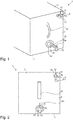
Im nachstehenden wird ein Ausführungsbeispiel der Erfindung an Hand einer Zeichnung beschrieben. Es zeigen:
- Fig. 1
- die Schrägansicht einer erfindungsgemäßen Tankanordnung; und
- Fig. 2
- eine Frontansicht der Vorderseite der in
Fig. 1 gezeigten Tankanordnung.
- Fig. 1
- the oblique view of a tank arrangement according to the invention; and
- Fig. 2
- a front view of the front of the
Fig. 1 shown tank arrangement.
In den
Die Lufteinlasseinrichtung 6 weist wie der Ablauf 10 eine innenliegende Ventileinrichtung 4b auf, welche über den Hebel 18b gesteuert werden kann. An der Lufteinlasseinrichtung befindet sich des weiterem ein Anschluss 14 wodurch der Lufteinlass 12 gebildet wird. An diesen Anschluss 14 kann z.B. ein hier nicht gezeigter Druckluftschlauch angeschlossen werden, wodurch dann über den Lufteinlass 12 Druckluft in das Innere des Tanks 2 gefördert werden kann. Die Dichtung 22, welche die Öffnung für die Lufteinlasseinrichtung 6 sowohl nach außen als auch nach innen abdichtet befindet sich zwischen der Außenwandung des Tanks 2 und der Lufteinlasseinrichtung 6.The
Die Anmelderin behält sich vor sämtliche in den Anmeldungsunterlagen offenbarten Merkmale als erfindungswesentlich zu beanspruchen, sofern sie einzeln oder in Kombination gegenüber dem Stand der Technik neu sind. Es wird weiterhin darauf hingewiesen, dass in den einzelnen Figuren auch Merkmale beschrieben wurden, welche für sich genommen vorteilhaft sein können. Der Fachmann erkennt unmittelbar, dass ein bestimmtes in einer Figur beschriebenes Merkmal auch ohne die Übernahme weiterer Merkmale aus dieser Figur vorteilhaft sein kann. Ferner erkennt der Fachmann, dass sich auch Vorteile durch eine Kombination mehrerer in einzelnen oder in unterschiedlichen Figuren gezeigter Merkmale ergeben können.The Applicant reserves the right to claim all features disclosed in the application documents as essential to the invention, provided that they are novel individually or in combination with respect to the prior art. It is further pointed out that features have also been described in the individual figures, which in themselves can be advantageous. The skilled artisan immediately recognizes that a particular in a figure described feature may be advantageous without the adoption of further features of this figure. Furthermore, the person skilled in the art recognizes that advantages can also result from a combination of several features shown in individual or in different figures.
- 11
- Tankanordnungtank assembly
- 22
- Tanktank
- 4 a, b4 a, b
- Ventileinrichtungvalve means
- 66
- LufteinlasseinrichtungAir inlet device
- 1010
- Ablaufprocedure
- 1212
- Lufteinlassair intake
- 1414
- Anschlussconnection
- 1616
- GriffHandle
- 18 a, b18 a, b
- Hebellever
- 2020
- ZulaufIntake
- 2222
- Dichtungpoetry
- 2424
- Schraubverschlussscrew
- UU
- Unterkantelower edge
- VV
- Vorderseitefront
Claims (15)
dadurch gekennzeichnet, dass
an dem Lufteinlass (12) eine Luftleitung anschließbar ist um den Tank (2) über die Lufteinlasseinrichtung (6) Luft zuzuführen.Tank arrangement (1) with a tank (2) with an inlet to fill the tank (2) with a flowable medium and a drain (10) to remove a medium from the tank (2), the outlet (10) a Valve device (4 a), which is manually via a lever (18 a) from an open position to a closed position and / or vice versa transferable wherein the tank (2) has an air inlet device (6) with an air inlet (12) over which air can be conveyed into the tank (2) in order to be able to vent the tank (2),
characterized in that
An air line can be connected to the air inlet (12) in order to supply air to the tank (2) via the air inlet device (6).
dadurch gekennzeichnet, dass
der Ablauf (10) und/ oder die Lufteinlasseinrichtung (6) an einer Vorderseite (V) des Tanks (2) angeordnet sind.Device (1) according to claim 1,
characterized in that
the outlet (10) and / or the air inlet device (6) are arranged on a front side (V) of the tank (2).
dadurch gekennzeichnet, dass
sich die Lufteinlasseinrichtung (6) oberhalb des Ablaufs (10) befindet.Device (1) according to claim 2,
characterized in that
the air inlet device (6) is above the outlet (10).
dadurch gekennzeichnet, dass
sich der Ablauf (10) bevorzugt mittig an einer Unterkante (U) des Tanks (2) befindet.Device (1) according to claims 2 and 3,
characterized in that
the outlet (10) is preferably located centrally on a lower edge (U) of the tank (2).
dadurch gekennzeichnet, dass
sich die Lufteinlasseinrichtung (6) diagonal über dem Ablauf (10) befindet.Device (1) according to claims 2 to 4,
characterized in that
the air inlet device (6) is located diagonally above the outlet (10).
dadurch gekennzeichnet, dass
die Lufteinlasseinrichtung (6) und/ oder das Auslassventil (10) form- oder kraftschlüssig mit dem Tank (2) verbunden sind.Device (1) according to one of the preceding claims,
characterized in that
the air inlet device (6) and / or the outlet valve (10) are positively or non-positively connected to the tank (2).
dadurch gekennzeichnet, dass
die Lufteinlasseinrichtung (6) und das Auslassventil (10) austauschbar an dem Tank (2) befestigt sind.Device (1) according to one of the preceding claims,
characterized in that
the air inlet device (6) and the outlet valve (10) are exchangeably attached to the tank (2).
dadurch gekennzeichnet, dass
es sich bei der Lufteinlasseinrichtung (6) um eine Einwegeinrichtung handelt.Device (1) according to one of the preceding claims,
characterized in that
the air inlet device (6) is a one-way device.
dadurch gekennzeichnet, dass
die Lufteinlasseinrichtung (6) einen Anschluss (14) für einen Druckluftschlauch aufweist.Device (1) according to claim 3,
characterized in that
the air inlet device (6) has a connection (14) for a compressed air hose.
dadurch gekennzeichnet, dass
die Lufteinlasseinrichtung (6) und/ oder der Ablauf (10) stufenlos regulierbar sind.Device (1) according to one of the preceding claims,
characterized in that
the air inlet device (6) and / or the outlet (10) are infinitely adjustable.
dadurch gekennzeichnet, dass
die Lufteinlasseinrichtung eine Ventileinrichtung (4b) aufweist.Device according to at least one of the preceding claims,
characterized in that
the air inlet device has a valve device (4b).
dadurch gekennzeichnet, dass
über die Ventileinrichtung (4b) auch überschüssige Druckluft aus dem Tank (2) abgeführt werden kann.Device (1) according to one of the preceding claims,
characterized in that
Over the valve means (4b) also excess compressed air from the tank (2) can be removed.
dadurch gekennzeichnet, dass
über die Venteinrichtung (4b), insbesondere über die Lufteinlasseinrichtung (6) fließfähiges Medium in und/ oder aus dem Tank (2) gefördert werden kann.Device (1) according to one of the preceding claims,
characterized in that
via the Venteinrichtung (4b), in particular via the air inlet device (6) flowable medium in and / or from the tank (2) can be promoted.
dadurch gekennzeichnet, dass
eine Luftleitung an den Lufteinlass (12) angeschlossen werden kann, um dem Tank (2) über die Lufteinlasseinrichtung (6) Luft zuführen zu können.A method for filling a tank (2) with a flowable medium and for removing the flowable medium from the tank (2), wherein the tank (2) has an inlet (20) and a drain (10) through which the flowable medium in the tank (2) can be introduced or discharged, wherein a valve means (4a) on the outlet (10) manually via a lever (18a) from an open position to a closed position and / or vice versa can be transferred wherein the tank (2 ) via an air inlet device (6) with an air inlet (12), via which air can be conveyed into the tank (2), can be vented,
characterized in that
an air line to the air inlet (12) can be connected to the tank (2) via the air inlet device (6) to be able to supply air.
dadurch gekennzeichnet, dass
über die Ventileinrichtung (4a) in dem Tank (2) angestaute Druckluft aus dem Tank (2) abgeführt werden kann.Method according to claim 14,
characterized in that
via the valve means (4a) in the tank (2) accumulated compressed air can be removed from the tank (2).
Priority Applications (1)
| Application Number | Priority Date | Filing Date | Title |
|---|---|---|---|
| PL18160677T PL3378829T3 (en) | 2017-03-14 | 2018-03-08 | Tank with ventilation |
Applications Claiming Priority (1)
| Application Number | Priority Date | Filing Date | Title |
|---|---|---|---|
| DE202017101477.0U DE202017101477U1 (en) | 2017-03-14 | 2017-03-14 | Tank with ventilation |
Publications (2)
| Publication Number | Publication Date |
|---|---|
| EP3378829A1 true EP3378829A1 (en) | 2018-09-26 |
| EP3378829B1 EP3378829B1 (en) | 2022-01-12 |
Family
ID=58584374
Family Applications (1)
| Application Number | Title | Priority Date | Filing Date |
|---|---|---|---|
| EP18160677.3A Active EP3378829B1 (en) | 2017-03-14 | 2018-03-08 | Tank with ventilation |
Country Status (5)
| Country | Link |
|---|---|
| EP (1) | EP3378829B1 (en) |
| DE (1) | DE202017101477U1 (en) |
| DK (1) | DK3378829T3 (en) |
| ES (1) | ES2907016T3 (en) |
| PL (1) | PL3378829T3 (en) |
Citations (7)
| Publication number | Priority date | Publication date | Assignee | Title |
|---|---|---|---|---|
| FR659396A (en) * | 1928-08-22 | 1929-06-27 | Method and arrangement for transporting wine by means of compressed air | |
| DE1657211A1 (en) * | 1968-01-30 | 1971-02-11 | Knopf Karl Horst | Carbonation device for beer kegs |
| US3712514A (en) * | 1971-03-29 | 1973-01-23 | R Leblanc | Portable beer dispenser |
| US6082589A (en) * | 1996-02-14 | 2000-07-04 | Ash; Fred L. | Slush beverage dispensing system |
| EP2243744A1 (en) * | 2009-04-23 | 2010-10-27 | Safety-Kleen Italia S.p.A. | Control valve for pressurising and depressurising a container, device for filling or emptying a container and device for closing a container |
| US20130264360A1 (en) * | 2012-04-05 | 2013-10-10 | Brewing Tools Llc | Reusable Vessel for Dispensing Beverages and Method of Storing and Dispensing Beverages |
| DE102014016558A1 (en) * | 2014-11-11 | 2016-05-12 | Max Mayer | Portable liquid tank |
-
2017
- 2017-03-14 DE DE202017101477.0U patent/DE202017101477U1/en active Active
-
2018
- 2018-03-08 PL PL18160677T patent/PL3378829T3/en unknown
- 2018-03-08 DK DK18160677.3T patent/DK3378829T3/en active
- 2018-03-08 ES ES18160677T patent/ES2907016T3/en active Active
- 2018-03-08 EP EP18160677.3A patent/EP3378829B1/en active Active
Patent Citations (7)
| Publication number | Priority date | Publication date | Assignee | Title |
|---|---|---|---|---|
| FR659396A (en) * | 1928-08-22 | 1929-06-27 | Method and arrangement for transporting wine by means of compressed air | |
| DE1657211A1 (en) * | 1968-01-30 | 1971-02-11 | Knopf Karl Horst | Carbonation device for beer kegs |
| US3712514A (en) * | 1971-03-29 | 1973-01-23 | R Leblanc | Portable beer dispenser |
| US6082589A (en) * | 1996-02-14 | 2000-07-04 | Ash; Fred L. | Slush beverage dispensing system |
| EP2243744A1 (en) * | 2009-04-23 | 2010-10-27 | Safety-Kleen Italia S.p.A. | Control valve for pressurising and depressurising a container, device for filling or emptying a container and device for closing a container |
| US20130264360A1 (en) * | 2012-04-05 | 2013-10-10 | Brewing Tools Llc | Reusable Vessel for Dispensing Beverages and Method of Storing and Dispensing Beverages |
| DE102014016558A1 (en) * | 2014-11-11 | 2016-05-12 | Max Mayer | Portable liquid tank |
Also Published As
| Publication number | Publication date |
|---|---|
| DE202017101477U1 (en) | 2017-04-03 |
| PL3378829T3 (en) | 2022-05-30 |
| EP3378829B1 (en) | 2022-01-12 |
| DK3378829T3 (en) | 2022-03-14 |
| ES2907016T3 (en) | 2022-04-21 |
Similar Documents
| Publication | Publication Date | Title |
|---|---|---|
| DE3222234C2 (en) | ||
| DE202010011973U1 (en) | Oil drain device | |
| EP3021034A1 (en) | Fitting for liquefied gas bottles and filling method | |
| DE1528889A1 (en) | Arrangement for restoring the suction capability of a pump | |
| DE102009035345A1 (en) | Device for extracting liquid sample i.e. water sample, from e.g. river, has ventilation opening arranged at distance to suction opening, and suction line associated with atmosphere or separated from atmosphere by ventilation opening | |
| EP2738032B1 (en) | Tank system for a motor vehicle | |
| WO2013102483A1 (en) | Method and device for separating gas from a medium stored in a reservoir | |
| DE102015205825B4 (en) | Method for the frost emptying of a fresh water container for a rail vehicle for passenger traffic and a rail vehicle for passenger traffic with a frost emptying device | |
| EP3378829B1 (en) | Tank with ventilation | |
| EP0787099A1 (en) | Device for airing a liquids container | |
| EP3657020B1 (en) | Evacuation device for a suction pipe | |
| DE102006021916A1 (en) | Device for degasification and / or pressure maintenance in a closed water cycle | |
| DE2103643B2 (en) | Washer system for windows of motor vehicles, in particular light exit windows for vehicle lights | |
| DE3523102C2 (en) | ||
| DE102017008037B4 (en) | Deep withdrawal device for liquid samples | |
| DE1607038A1 (en) | Vacuum regulator for milking equipment | |
| DE19932859C2 (en) | Aseptic pump housing with switchable drainage | |
| DE3602079A1 (en) | Device for transferring liquids | |
| DE1963539B2 (en) | Valve device for taking liquid samples from a treatment apparatus under vacuum | |
| DE508940C (en) | Device for the sedimentation of fluids developing gases from closed boreholes | |
| DE1607017C3 (en) | Device for taking milk from milk containers into milk collecting containers, in particular milk collecting trucks | |
| DE102015115884A1 (en) | cleaning system | |
| DE102016109436B4 (en) | Installation and method for dispensing liquid from a tank truck | |
| DE2331982A1 (en) | Hydraulic system for medical apparatus - oil-tight oil supply container box for larger vol. than oil received | |
| EP3218278B1 (en) | Container with venting channel |
Legal Events
| Date | Code | Title | Description |
|---|---|---|---|
| PUAI | Public reference made under article 153(3) epc to a published international application that has entered the european phase |
Free format text: ORIGINAL CODE: 0009012 |
|
| STAA | Information on the status of an ep patent application or granted ep patent |
Free format text: STATUS: THE APPLICATION HAS BEEN PUBLISHED |
|
| AK | Designated contracting states |
Kind code of ref document: A1 Designated state(s): AL AT BE BG CH CY CZ DE DK EE ES FI FR GB GR HR HU IE IS IT LI LT LU LV MC MK MT NL NO PL PT RO RS SE SI SK SM TR |
|
| AX | Request for extension of the european patent |
Extension state: BA ME |
|
| STAA | Information on the status of an ep patent application or granted ep patent |
Free format text: STATUS: REQUEST FOR EXAMINATION WAS MADE |
|
| STAA | Information on the status of an ep patent application or granted ep patent |
Free format text: STATUS: REQUEST FOR EXAMINATION WAS MADE |
|
| 17P | Request for examination filed |
Effective date: 20190326 |
|
| RBV | Designated contracting states (corrected) |
Designated state(s): AL AT BE BG CH CY CZ DE DK EE ES FI FR GB GR HR HU IE IS IT LI LT LU LV MC MK MT NL NO PL PT RO RS SE SI SK SM TR |
|
| RIC1 | Information provided on ipc code assigned before grant |
Ipc: B67D 1/00 20060101AFI20210331BHEP Ipc: B67D 1/04 20060101ALI20210331BHEP Ipc: B67D 3/00 20060101ALI20210331BHEP Ipc: B67D 7/02 20100101ALI20210331BHEP Ipc: B67D 1/08 20060101ALN20210331BHEP |
|
| GRAP | Despatch of communication of intention to grant a patent |
Free format text: ORIGINAL CODE: EPIDOSNIGR1 |
|
| STAA | Information on the status of an ep patent application or granted ep patent |
Free format text: STATUS: GRANT OF PATENT IS INTENDED |
|
| RIC1 | Information provided on ipc code assigned before grant |
Ipc: B67D 1/00 20060101AFI20210506BHEP Ipc: B67D 1/04 20060101ALI20210506BHEP Ipc: B67D 3/00 20060101ALI20210506BHEP Ipc: B67D 7/02 20100101ALI20210506BHEP Ipc: B67D 1/08 20060101ALN20210506BHEP |
|
| INTG | Intention to grant announced |
Effective date: 20210520 |
|
| GRAJ | Information related to disapproval of communication of intention to grant by the applicant or resumption of examination proceedings by the epo deleted |
Free format text: ORIGINAL CODE: EPIDOSDIGR1 |
|
| STAA | Information on the status of an ep patent application or granted ep patent |
Free format text: STATUS: REQUEST FOR EXAMINATION WAS MADE |
|
| INTC | Intention to grant announced (deleted) | ||
| GRAS | Grant fee paid |
Free format text: ORIGINAL CODE: EPIDOSNIGR3 |
|
| STAA | Information on the status of an ep patent application or granted ep patent |
Free format text: STATUS: GRANT OF PATENT IS INTENDED |
|
| GRAP | Despatch of communication of intention to grant a patent |
Free format text: ORIGINAL CODE: EPIDOSNIGR1 |
|
| RIC1 | Information provided on ipc code assigned before grant |
Ipc: B67D 1/08 20060101ALN20211020BHEP Ipc: B67D 7/02 20100101ALI20211020BHEP Ipc: B67D 3/00 20060101ALI20211020BHEP Ipc: B67D 1/04 20060101ALI20211020BHEP Ipc: B67D 1/00 20060101AFI20211020BHEP |
|
| GRAA | (expected) grant |
Free format text: ORIGINAL CODE: 0009210 |
|
| STAA | Information on the status of an ep patent application or granted ep patent |
Free format text: STATUS: THE PATENT HAS BEEN GRANTED |
|
| INTG | Intention to grant announced |
Effective date: 20211125 |
|
| AK | Designated contracting states |
Kind code of ref document: B1 Designated state(s): AL AT BE BG CH CY CZ DE DK EE ES FI FR GB GR HR HU IE IS IT LI LT LU LV MC MK MT NL NO PL PT RO RS SE SI SK SM TR |
|
| REG | Reference to a national code |
Ref country code: GB Ref legal event code: FG4D Free format text: NOT ENGLISH |
|
| REG | Reference to a national code |
Ref country code: CH Ref legal event code: EP |
|
| REG | Reference to a national code |
Ref country code: DE Ref legal event code: R096 Ref document number: 502018008481 Country of ref document: DE |
|
| REG | Reference to a national code |
Ref country code: IE Ref legal event code: FG4D Free format text: LANGUAGE OF EP DOCUMENT: GERMAN |
|
| REG | Reference to a national code |
Ref country code: AT Ref legal event code: REF Ref document number: 1462271 Country of ref document: AT Kind code of ref document: T Effective date: 20220215 |
|
| REG | Reference to a national code |
Ref country code: DK Ref legal event code: T3 Effective date: 20220310 |
|
| REG | Reference to a national code |
Ref country code: NL Ref legal event code: FP |
|
| REG | Reference to a national code |
Ref country code: ES Ref legal event code: FG2A Ref document number: 2907016 Country of ref document: ES Kind code of ref document: T3 Effective date: 20220421 |
|
| REG | Reference to a national code |
Ref country code: LT Ref legal event code: MG9D |
|
| PG25 | Lapsed in a contracting state [announced via postgrant information from national office to epo] |
Ref country code: SE Free format text: LAPSE BECAUSE OF FAILURE TO SUBMIT A TRANSLATION OF THE DESCRIPTION OR TO PAY THE FEE WITHIN THE PRESCRIBED TIME-LIMIT Effective date: 20220112 Ref country code: RS Free format text: LAPSE BECAUSE OF FAILURE TO SUBMIT A TRANSLATION OF THE DESCRIPTION OR TO PAY THE FEE WITHIN THE PRESCRIBED TIME-LIMIT Effective date: 20220112 Ref country code: PT Free format text: LAPSE BECAUSE OF FAILURE TO SUBMIT A TRANSLATION OF THE DESCRIPTION OR TO PAY THE FEE WITHIN THE PRESCRIBED TIME-LIMIT Effective date: 20220512 Ref country code: NO Free format text: LAPSE BECAUSE OF FAILURE TO SUBMIT A TRANSLATION OF THE DESCRIPTION OR TO PAY THE FEE WITHIN THE PRESCRIBED TIME-LIMIT Effective date: 20220412 Ref country code: LT Free format text: LAPSE BECAUSE OF FAILURE TO SUBMIT A TRANSLATION OF THE DESCRIPTION OR TO PAY THE FEE WITHIN THE PRESCRIBED TIME-LIMIT Effective date: 20220112 Ref country code: HR Free format text: LAPSE BECAUSE OF FAILURE TO SUBMIT A TRANSLATION OF THE DESCRIPTION OR TO PAY THE FEE WITHIN THE PRESCRIBED TIME-LIMIT Effective date: 20220112 Ref country code: BG Free format text: LAPSE BECAUSE OF FAILURE TO SUBMIT A TRANSLATION OF THE DESCRIPTION OR TO PAY THE FEE WITHIN THE PRESCRIBED TIME-LIMIT Effective date: 20220412 |
|
| PG25 | Lapsed in a contracting state [announced via postgrant information from national office to epo] |
Ref country code: LV Free format text: LAPSE BECAUSE OF FAILURE TO SUBMIT A TRANSLATION OF THE DESCRIPTION OR TO PAY THE FEE WITHIN THE PRESCRIBED TIME-LIMIT Effective date: 20220112 Ref country code: GR Free format text: LAPSE BECAUSE OF FAILURE TO SUBMIT A TRANSLATION OF THE DESCRIPTION OR TO PAY THE FEE WITHIN THE PRESCRIBED TIME-LIMIT Effective date: 20220413 Ref country code: FI Free format text: LAPSE BECAUSE OF FAILURE TO SUBMIT A TRANSLATION OF THE DESCRIPTION OR TO PAY THE FEE WITHIN THE PRESCRIBED TIME-LIMIT Effective date: 20220112 |
|
| PG25 | Lapsed in a contracting state [announced via postgrant information from national office to epo] |
Ref country code: IS Free format text: LAPSE BECAUSE OF FAILURE TO SUBMIT A TRANSLATION OF THE DESCRIPTION OR TO PAY THE FEE WITHIN THE PRESCRIBED TIME-LIMIT Effective date: 20220512 |
|
| REG | Reference to a national code |
Ref country code: DE Ref legal event code: R097 Ref document number: 502018008481 Country of ref document: DE |
|
| PG25 | Lapsed in a contracting state [announced via postgrant information from national office to epo] |
Ref country code: SM Free format text: LAPSE BECAUSE OF FAILURE TO SUBMIT A TRANSLATION OF THE DESCRIPTION OR TO PAY THE FEE WITHIN THE PRESCRIBED TIME-LIMIT Effective date: 20220112 Ref country code: SK Free format text: LAPSE BECAUSE OF FAILURE TO SUBMIT A TRANSLATION OF THE DESCRIPTION OR TO PAY THE FEE WITHIN THE PRESCRIBED TIME-LIMIT Effective date: 20220112 Ref country code: RO Free format text: LAPSE BECAUSE OF FAILURE TO SUBMIT A TRANSLATION OF THE DESCRIPTION OR TO PAY THE FEE WITHIN THE PRESCRIBED TIME-LIMIT Effective date: 20220112 Ref country code: MC Free format text: LAPSE BECAUSE OF FAILURE TO SUBMIT A TRANSLATION OF THE DESCRIPTION OR TO PAY THE FEE WITHIN THE PRESCRIBED TIME-LIMIT Effective date: 20220112 Ref country code: EE Free format text: LAPSE BECAUSE OF FAILURE TO SUBMIT A TRANSLATION OF THE DESCRIPTION OR TO PAY THE FEE WITHIN THE PRESCRIBED TIME-LIMIT Effective date: 20220112 |
|
| PLBE | No opposition filed within time limit |
Free format text: ORIGINAL CODE: 0009261 |
|
| STAA | Information on the status of an ep patent application or granted ep patent |
Free format text: STATUS: NO OPPOSITION FILED WITHIN TIME LIMIT |
|
| PG25 | Lapsed in a contracting state [announced via postgrant information from national office to epo] |
Ref country code: AL Free format text: LAPSE BECAUSE OF FAILURE TO SUBMIT A TRANSLATION OF THE DESCRIPTION OR TO PAY THE FEE WITHIN THE PRESCRIBED TIME-LIMIT Effective date: 20220112 |
|
| 26N | No opposition filed |
Effective date: 20221013 |
|
| PG25 | Lapsed in a contracting state [announced via postgrant information from national office to epo] |
Ref country code: LU Free format text: LAPSE BECAUSE OF NON-PAYMENT OF DUE FEES Effective date: 20220308 |
|
| PG25 | Lapsed in a contracting state [announced via postgrant information from national office to epo] |
Ref country code: SI Free format text: LAPSE BECAUSE OF FAILURE TO SUBMIT A TRANSLATION OF THE DESCRIPTION OR TO PAY THE FEE WITHIN THE PRESCRIBED TIME-LIMIT Effective date: 20220112 |
|
| PGFP | Annual fee paid to national office [announced via postgrant information from national office to epo] |
Ref country code: IE Payment date: 20230320 Year of fee payment: 6 Ref country code: FR Payment date: 20230320 Year of fee payment: 6 Ref country code: DK Payment date: 20230323 Year of fee payment: 6 Ref country code: CZ Payment date: 20230227 Year of fee payment: 6 Ref country code: AT Payment date: 20230317 Year of fee payment: 6 |
|
| PGFP | Annual fee paid to national office [announced via postgrant information from national office to epo] |
Ref country code: PL Payment date: 20230301 Year of fee payment: 6 Ref country code: GB Payment date: 20230323 Year of fee payment: 6 Ref country code: DE Payment date: 20230317 Year of fee payment: 6 Ref country code: BE Payment date: 20230321 Year of fee payment: 6 |
|
| P01 | Opt-out of the competence of the unified patent court (upc) registered |
Effective date: 20230521 |
|
| PGFP | Annual fee paid to national office [announced via postgrant information from national office to epo] |
Ref country code: NL Payment date: 20230322 Year of fee payment: 6 |
|
| PGFP | Annual fee paid to national office [announced via postgrant information from national office to epo] |
Ref country code: IT Payment date: 20230331 Year of fee payment: 6 Ref country code: ES Payment date: 20230414 Year of fee payment: 6 Ref country code: CH Payment date: 20230402 Year of fee payment: 6 |
|
| PG25 | Lapsed in a contracting state [announced via postgrant information from national office to epo] |
Ref country code: HU Free format text: LAPSE BECAUSE OF FAILURE TO SUBMIT A TRANSLATION OF THE DESCRIPTION OR TO PAY THE FEE WITHIN THE PRESCRIBED TIME-LIMIT; INVALID AB INITIO Effective date: 20180308 |
|
| PGFP | Annual fee paid to national office [announced via postgrant information from national office to epo] |
Ref country code: NL Payment date: 20240319 Year of fee payment: 7 Ref country code: IE Payment date: 20240320 Year of fee payment: 7 |