EP3378774A1 - Release lever for a parachute rescue system - Google Patents
Release lever for a parachute rescue system Download PDFInfo
- Publication number
- EP3378774A1 EP3378774A1 EP17161974.5A EP17161974A EP3378774A1 EP 3378774 A1 EP3378774 A1 EP 3378774A1 EP 17161974 A EP17161974 A EP 17161974A EP 3378774 A1 EP3378774 A1 EP 3378774A1
- Authority
- EP
- European Patent Office
- Prior art keywords
- handle
- lever
- console
- rotatable lever
- aircraft
- Prior art date
- Legal status (The legal status is an assumption and is not a legal conclusion. Google has not performed a legal analysis and makes no representation as to the accuracy of the status listed.)
- Granted
Links
Images



Classifications
-
- B—PERFORMING OPERATIONS; TRANSPORTING
- B64—AIRCRAFT; AVIATION; COSMONAUTICS
- B64D—EQUIPMENT FOR FITTING IN OR TO AIRCRAFT; FLIGHT SUITS; PARACHUTES; ARRANGEMENT OR MOUNTING OF POWER PLANTS OR PROPULSION TRANSMISSIONS IN AIRCRAFT
- B64D17/00—Parachutes
- B64D17/80—Parachutes in association with aircraft, e.g. for braking thereof
-
- F—MECHANICAL ENGINEERING; LIGHTING; HEATING; WEAPONS; BLASTING
- F16—ENGINEERING ELEMENTS AND UNITS; GENERAL MEASURES FOR PRODUCING AND MAINTAINING EFFECTIVE FUNCTIONING OF MACHINES OR INSTALLATIONS; THERMAL INSULATION IN GENERAL
- F16C—SHAFTS; FLEXIBLE SHAFTS; ELEMENTS OR CRANKSHAFT MECHANISMS; ROTARY BODIES OTHER THAN GEARING ELEMENTS; BEARINGS
- F16C1/00—Flexible shafts; Mechanical means for transmitting movement in a flexible sheathing
- F16C1/10—Means for transmitting linear movement in a flexible sheathing, e.g. "Bowden-mechanisms"
- F16C1/12—Arrangements for transmitting movement to or from the flexible member
Definitions
- the object of the invention is a release lever, especially for a parachute rescue system of a light aircraft, with a jet engine mounted on the aircraft fuselage.
- Solutions of levers for parachute rescue systems which have a handle seated in the body.
- the body is mounted to the fuselage structure in the aircraft cabin.
- the end of the handle is connected to a tension member to the fuse of a dragging rocket. Pulling the handle out of the body via the tension member activates the fuse of the dragging rocket.
- the parachute In the case of ultralight aircrafts, due to their low mass, it is possible to use the parachute to rescue the machine with the crew.
- the parachute is mounted to the aircraft and allows landing of the whole unit together with the crew, without having to leave the aircraft.
- the parachute is built over in the fuselage in a place intended therefor. Usually, it is packed into a bag made of a special material and protected from moisture and dust.
- the parachute for the aircraft In the case of aircrafts with a non-built-over cabin having a frame structure, the parachute for the aircraft is packed into a cylindrical container.
- Known release levers for parachute rescue systems operate in a single step. Their task is solely to launch a rocket which is designed to raise the parachute canopy over the aircraft. They are suitable for use in the case of aircrafts with a non-built-over cabin having a frame structure. In the built-over aircrafts, launching the rocket causes extraction of a special piece of the aircraft plating.
- the aim of the invention is to develop such a structure of the release lever for parachute rescue systems which will operate in two steps, i.e. will allow opening of the lid of the parachute container, and then activation of the fuse of the rescue rocket.
- the release lever especially for the parachute rescue system of a light aircraft, with a jet engine mounted on the aircraft fuselage, comprising a handle arranged in the body mounted to the fuselage structure in the aircraft cabin, is characterised in that the body consists of a console and a rotatable lever, tiltable from the resting position to the operating position, rotatably mounted in the console, wherein the console is mounted to the aircraft fuselage structure, and the handle is seated inside the rotatable lever and protrudes beyond the rotatable lever, wherein the handle is provided with a locking mechanism which prevents pulling the handle out of the rotatable lever before it is tilted from the resting position to the operating position.
- the console has a base with fixing components and walls perpendicular to the base, and the rotatable lever is provided with a guide in a form of a circular sector, the guide being located at the end of the rotatable lever, and the end being located between the console walls, wherein there is a fixing seat on the edge of the guide, and the handle has a through hole extending along its axis, terminated with a seat at the end of the handle, the seat protruding beyond the rotatable lever.
- the locking mechanism which prevents pulling the handle out of the rotatable lever before it is tilted from the resting position to the operating position, contains balls arranged in seats located in the side walls of the rotatable lever and of the handle, the balls being prevented from falling out in the resting position with the console walls.
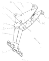
- Fig. 1 shows a release lever in the resting position in a 3 ⁇ 4 perspective view from the bottom
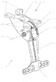
- Fig. 2 shows a release lever in the operating position in a 3 ⁇ 4 perspective view from the bottom
- Fig. 3 shows a release lever in a position close to the operating position in a 3 ⁇ 4 perspective view from the bottom
- Fig. 4 shows a longitudinal section through a release lever in the resting position
- Fig. 5 shows a release lever in the parachute rescue system.
- a release lever 1 especially relates to a parachute rescue system of a light aircraft, with a jet engine mounted on the aircraft 2 fuselage.
- the release lever 1 comprises a handle 7 arranged in the body mounted to the fuselage structure in the aircraft 2 cabin.
- the body consists of a console 4 and a rotatable lever 5 rotatably mounted in the console 4 on a rotation axis 6.
- the rotatable lever 5 can be tilted from the resting position, shown in Fig. 1 , to the operating position, shown in Fig. 2 .
- the console 4 has a base 8 with fixing components 9 and walls 10 perpendicular to the base 8. In the fixing components 9, there are holes for mounting the console 4 in the cabin to the aircraft 2 structure, for example by means of screws.
- the handle 7 is seated inside the rotatable lever 5 and protrudes beyond the rotatable lever 5, wherein the handle 7 is provided with a locking mechanism 3 which prevents pulling the handle 7 out of the rotatable lever 5 before it is tilted from the resting position, shown in Fig. 1 , to the operating position, shown in Fig. 2 .
- a locking mechanism 3 which prevents pulling the handle 7 out of the rotatable lever 5 before it is tilted from the resting position, shown in Fig. 1 , to the operating position, shown in Fig. 2 .
- the locking mechanism 3 which prevents pulling the handle 7 out of the rotatable lever 5 before it is tilted from the resting position to the operating position, contains balls 12 arranged in seats 13 located in the side walls of the rotatable lever 5 and of the handle 7, the balls being prevented from falling out in the resting position with the console 4 walls 10. It is obvious that in another embodiment of the invention, the locking mechanism 3 may be used, which prevents pulling the handle 7 out of the rotatable lever 5 before it is tilted from the resting position to the operating position, having a different known structure.
- the rotatable lever is provided with a guide 11 in a form of a circular sector, the guide being located at the end of the rotatable lever 5, and the end being located between the console 4 walls 10.
- a guide 11 On the ridge of the guide 11, there is a profiled groove, and on the edge of the guide 11, there is a fixing seat 16.
- the handle 7 has a through hole 14 extending along its axis, terminated with a seat 15 at the end of the handle 7, the seat protruding beyond the rotatable lever 5.
- the release lever 1 is used to activate the parachute rescue system of a light aircraft 2, especially an aircraft 2 with a jet engine 25 mounted on the aircraft 2 fuselage.
- the location of the release lever 1 in the parachute rescue system is shown in Fig. 5 .
- the parachute rescue system comprises a parachute 21 arranged in a container 20 provided with an openable lid 22 at the top, constituting part of the plating of the aircraft 2 fuselage.
- the lid 22 is closed with a lid lock 19 connected, with a lid tension member 17, to the fixing seat 16 located on the edge of the guide 11 of the release lever 1.
- the parachute 21 is connected to the aircraft 2 structure.
- the fuse of the dragging rocket 23 is connected, through the rocket tension member 18, to the handle 7 of the release lever 1.
- the container 20 with the parachute 21 is arranged in the aircraft 2 fuselage upstream of the inlet of air into the jet engine 25.
- the lid 22 of the container 20 is rotatably mounted on its rear edge. The distance between the rear edge of the lid 22 and the inlet of air into the jet engine 25 is smaller that the length of the lid 22 in the longitudinal direction.
- the release lever 1 activates the parachute rescue system in two steps.
- the operator wishes to activate the rescue system, he pulls the handle 7, thereby moving the rotatable lever 5 of the release lever 1 from the resting position, shown in Fig. 1 , to the operating position, shown in Fig. 2 .
- This movement causes pulling of the lid tension member 17 and opening of the lid lock 19 of the container 20 of the parachute 21.
- the container 20 for the parachute 21 is opened, and the lid 22 of the container 20 abuts against the inlet of air into the jet engine 25.
- the release lever 1 according to the invention is a solution which allows activation of the rescue system, providing a two-step action with a single lever.
- the release lever 1 according to the invention By means of the release lever 1 according to the invention, the lid 22 of the container 20 for the parachute 21 is opened, and then the fuse of the dragging rocket 23 is activated. The two-step action immediately takes place.
- the pilot uses one handle 7, the rotation of which about the axis 6 on the console 4, causes opening of the lid 22 of the container, and pulling out of the rotatable lever 5 launches the dragging rocket 23.
Landscapes
- Engineering & Computer Science (AREA)
- General Engineering & Computer Science (AREA)
- Health & Medical Sciences (AREA)
- Oral & Maxillofacial Surgery (AREA)
- Mechanical Engineering (AREA)
- Aviation & Aerospace Engineering (AREA)
- Emergency Lowering Means (AREA)
Abstract
the release lever (1) comprising a handle (7) arranged in the body mounted to the fuselage structure in the aircraft (1) cabin. characterised in that the body consists of a console (4) and a rotatable lever (5), tiltable from the resting position to the operating position, rotatably mounted in the console (4), wherein the console (4) is mounted to the aircraft (2) fuselage structure, and the handle (7) is seated inside the rotatable lever (5) and protrudes beyond the rotatable lever (5), wherein the handle (7) is provided with a locking mechanism (3) which prevents pulling the handle (7) out of the rotatable lever (5) before it is tilted from the resting position to the operating position.
Description
- The object of the invention is a release lever, especially for a parachute rescue system of a light aircraft, with a jet engine mounted on the aircraft fuselage.
- Solutions of levers for parachute rescue systems are known which have a handle seated in the body. The body is mounted to the fuselage structure in the aircraft cabin. The end of the handle is connected to a tension member to the fuse of a dragging rocket. Pulling the handle out of the body via the tension member activates the fuse of the dragging rocket.
- In the case of ultralight aircrafts, due to their low mass, it is possible to use the parachute to rescue the machine with the crew. The parachute is mounted to the aircraft and allows landing of the whole unit together with the crew, without having to leave the aircraft. The parachute is built over in the fuselage in a place intended therefor. Usually, it is packed into a bag made of a special material and protected from moisture and dust. In the case of aircrafts with a non-built-over cabin having a frame structure, the parachute for the aircraft is packed into a cylindrical container.
- Known release levers for parachute rescue systems operate in a single step. Their task is solely to launch a rocket which is designed to raise the parachute canopy over the aircraft. They are suitable for use in the case of aircrafts with a non-built-over cabin having a frame structure. In the built-over aircrafts, launching the rocket causes extraction of a special piece of the aircraft plating.
- The aim of the invention is to develop such a structure of the release lever for parachute rescue systems which will operate in two steps, i.e. will allow opening of the lid of the parachute container, and then activation of the fuse of the rescue rocket.
- The release lever, according to the invention, especially for the parachute rescue system of a light aircraft, with a jet engine mounted on the aircraft fuselage, comprising a handle arranged in the body mounted to the fuselage structure in the aircraft cabin, is characterised in that the body consists of a console and a rotatable lever, tiltable from the resting position to the operating position, rotatably mounted in the console, wherein the console is mounted to the aircraft fuselage structure, and the handle is seated inside the rotatable lever and protrudes beyond the rotatable lever, wherein the handle is provided with a locking mechanism which prevents pulling the handle out of the rotatable lever before it is tilted from the resting position to the operating position.
- It is preferable if the console has a base with fixing components and walls perpendicular to the base, and the rotatable lever is provided with a guide in a form of a circular sector, the guide being located at the end of the rotatable lever, and the end being located between the console walls, wherein there is a fixing seat on the edge of the guide, and the handle has a through hole extending along its axis, terminated with a seat at the end of the handle, the seat protruding beyond the rotatable lever.
- It is also preferable if the locking mechanism which prevents pulling the handle out of the rotatable lever before it is tilted from the resting position to the operating position, contains balls arranged in seats located in the side walls of the rotatable lever and of the handle, the balls being prevented from falling out in the resting position with the console walls.
- The object of the invention is presented in embodiments in the drawing, in which
Fig. 1 shows a release lever in the resting position in a ¾ perspective view from the bottom,Fig. 2 shows a release lever in the operating position in a ¾ perspective view from the bottom,Fig. 3 shows a release lever in a position close to the operating position in a ¾ perspective view from the bottom,Fig. 4 shows a longitudinal section through a release lever in the resting position, andFig. 5 shows a release lever in the parachute rescue system. - A
release lever 1 especially relates to a parachute rescue system of a light aircraft, with a jet engine mounted on the aircraft 2 fuselage. As shown inFig. 1 ,Fig. 2 ,Fig. 3 andFig. 4 , therelease lever 1 comprises ahandle 7 arranged in the body mounted to the fuselage structure in the aircraft 2 cabin. The body consists of a console 4 and arotatable lever 5 rotatably mounted in the console 4 on arotation axis 6. Therotatable lever 5 can be tilted from the resting position, shown inFig. 1 , to the operating position, shown inFig. 2 . The console 4 has abase 8 with fixing components 9 andwalls 10 perpendicular to thebase 8. In the fixing components 9, there are holes for mounting the console 4 in the cabin to the aircraft 2 structure, for example by means of screws. - As shown in
Fig. 4 , thehandle 7 is seated inside therotatable lever 5 and protrudes beyond therotatable lever 5, wherein thehandle 7 is provided with a locking mechanism 3 which prevents pulling thehandle 7 out of therotatable lever 5 before it is tilted from the resting position, shown inFig. 1 , to the operating position, shown inFig. 2 . As shown inFig. 4 , in an embodiment of the invention, the locking mechanism 3 which prevents pulling thehandle 7 out of therotatable lever 5 before it is tilted from the resting position to the operating position, containsballs 12 arranged inseats 13 located in the side walls of therotatable lever 5 and of thehandle 7, the balls being prevented from falling out in the resting position with the console 4walls 10. It is obvious that in another embodiment of the invention, the locking mechanism 3 may be used, which prevents pulling thehandle 7 out of therotatable lever 5 before it is tilted from the resting position to the operating position, having a different known structure. - As shown in
Fig. 3 , the rotatable lever is provided with a guide 11 in a form of a circular sector, the guide being located at the end of therotatable lever 5, and the end being located between the console 4walls 10. On the ridge of the guide 11, there is a profiled groove, and on the edge of the guide 11, there is afixing seat 16. - As shown in
Fig. 4 , thehandle 7 has a throughhole 14 extending along its axis, terminated with a seat 15 at the end of thehandle 7, the seat protruding beyond therotatable lever 5. - The
release lever 1 is used to activate the parachute rescue system of a light aircraft 2, especially an aircraft 2 with ajet engine 25 mounted on the aircraft 2 fuselage. The location of therelease lever 1 in the parachute rescue system is shown inFig. 5 . The parachute rescue system comprises a parachute 21 arranged in acontainer 20 provided with anopenable lid 22 at the top, constituting part of the plating of the aircraft 2 fuselage. Thelid 22 is closed with a lid lock 19 connected, with a lid tension member 17, to thefixing seat 16 located on the edge of the guide 11 of therelease lever 1. On thelid 22, from the inner side, adragging rocket 23 connected to the parachute canopy 21 is mounted. The parachute 21 is connected to the aircraft 2 structure. The fuse of thedragging rocket 23 is connected, through the rocket tension member 18, to thehandle 7 of therelease lever 1. - The
container 20 with the parachute 21 is arranged in the aircraft 2 fuselage upstream of the inlet of air into thejet engine 25. Thelid 22 of thecontainer 20 is rotatably mounted on its rear edge. The distance between the rear edge of thelid 22 and the inlet of air into thejet engine 25 is smaller that the length of thelid 22 in the longitudinal direction. - The
release lever 1 activates the parachute rescue system in two steps. When the operator wishes to activate the rescue system, he pulls thehandle 7, thereby moving therotatable lever 5 of therelease lever 1 from the resting position, shown inFig. 1 , to the operating position, shown inFig. 2 . This movement causes pulling of the lid tension member 17 and opening of the lid lock 19 of thecontainer 20 of the parachute 21. Thecontainer 20 for the parachute 21 is opened, and thelid 22 of thecontainer 20 abuts against the inlet of air into thejet engine 25. In the operating position, theballs 12, arranged in theseats 13 located in the side walls of therotatable lever 5 and of thehandle 7, which are prevented from falling out in the resting position with the console 4walls 10, fall out. Now, it is possible to pull thehandle 7 out of therotatable lever 5. One end of the rocket tension member 18 is connected to the fuse of therocket 23, and the other end passes through the throughhole 14 in thehandle 7 and is mounted in the seat 15 at the end of thehandle 7. Pulling thehandle 7 out of therotatable lever 5 causes launching of thedragging rocket 23. At the time of activating the parachute rescue system in the aircraft 2, thelid 22 opens towards the back of the aircraft, covering at the same time the inlet of air into thejet engine 25. Then, thedragging rocket 23 mounted on the inner side of theopenable lid 22 is launched and drags the parachute canopy 21 outside of thecontainer 20 above the surface of the aircraft 2. Covering the inlet of air into thejet engine 25 by thelid 22 assures safe removal of the parachute canopy 21 from thecontainer 20 above the aircraft 2, which as a result allows its proper opening at the right moment. - The release lever 1 according to the invention is a solution which allows activation of the rescue system, providing a two-step action with a single lever. By means of the release lever 1 according to the invention, the
lid 22 of thecontainer 20 for the parachute 21 is opened, and then the fuse of thedragging rocket 23 is activated. The two-step action immediately takes place. The pilot uses onehandle 7, the rotation of which about theaxis 6 on the console 4, causes opening of thelid 22 of the container, and pulling out of therotatable lever 5 launches thedragging rocket 23.
Claims (3)
- A release lever, especially for a parachute rescue system of a light aircraft, with a jet engine mounted on the aircraft fuselage, the release lever comprising a handle arranged in the body mounted to the fuselage structure in the aircraft cabin, characterised in that the body consists of a console (4) and a rotatable lever (5) tiltable from the resting position to the operating position, rotatably mounted in the console (4), wherein the console (4) is mounted to the aircraft (2) fuselage structure, and the handle (7) is seated inside the rotatable lever (5) and protrudes beyond the rotatable lever (5), wherein the handle (7) is provided with a locking mechanism (3) which prevents pulling the handle (7) out of the rotatable lever (5) before it is tilted from the resting position to the operating position.
- The lever according to claim 1, characterised in that the console (4) has a base (8) with fixing components (9), and walls (10) perpendicular to the base (8), and the rotatable lever (5) is provided with a guide (11) in a form of a circular sector, the guide being located at the end of the rotatable lever (5), the end being located between the console (5) walls (10), wherein there is a fixing seat (16) on the edge of the guide (11), and the handle (7) has a through hole (14) extending along its axis, terminated with a seat (15) at the end of the handle (7), the seat protruding beyond the rotatable lever (5).
- The lever according to claim 1, characterised in that the locking mechanism (3), which prevents pulling the handle (7) out of the rotatable lever (5) before it is tilted from the resting position to the operating position, contains balls (12) arranged in seats (13) located in the side walls of the rotatable lever (5) and of the handle (7), the balls being prevented from falling out in the resting position with the console (4) walls (10).
Priority Applications (1)
| Application Number | Priority Date | Filing Date | Title |
|---|---|---|---|
| EP17161974.5A EP3378774B1 (en) | 2017-03-21 | 2017-03-21 | Release lever for a parachute rescue system |
Applications Claiming Priority (1)
| Application Number | Priority Date | Filing Date | Title |
|---|---|---|---|
| EP17161974.5A EP3378774B1 (en) | 2017-03-21 | 2017-03-21 | Release lever for a parachute rescue system |
Publications (2)
| Publication Number | Publication Date |
|---|---|
| EP3378774A1 true EP3378774A1 (en) | 2018-09-26 |
| EP3378774B1 EP3378774B1 (en) | 2020-02-12 |
Family
ID=58398069
Family Applications (1)
| Application Number | Title | Priority Date | Filing Date |
|---|---|---|---|
| EP17161974.5A Active EP3378774B1 (en) | 2017-03-21 | 2017-03-21 | Release lever for a parachute rescue system |
Country Status (1)
| Country | Link |
|---|---|
| EP (1) | EP3378774B1 (en) |
Citations (3)
| Publication number | Priority date | Publication date | Assignee | Title |
|---|---|---|---|---|
| GB877796A (en) * | 1958-02-21 | 1961-09-20 | Avro Aircraft Ltd | Mechanical actuating device |
| GB1220827A (en) * | 1967-09-13 | 1971-01-27 | Ml Aviation Co Ltd | Improvements relating to brake parachute systems for aircraft |
| US5409187A (en) * | 1992-11-13 | 1995-04-25 | Dunham; John | Rocket deployment system for parachutes and the like |
-
2017
- 2017-03-21 EP EP17161974.5A patent/EP3378774B1/en active Active
Patent Citations (3)
| Publication number | Priority date | Publication date | Assignee | Title |
|---|---|---|---|---|
| GB877796A (en) * | 1958-02-21 | 1961-09-20 | Avro Aircraft Ltd | Mechanical actuating device |
| GB1220827A (en) * | 1967-09-13 | 1971-01-27 | Ml Aviation Co Ltd | Improvements relating to brake parachute systems for aircraft |
| US5409187A (en) * | 1992-11-13 | 1995-04-25 | Dunham; John | Rocket deployment system for parachutes and the like |
Also Published As
| Publication number | Publication date |
|---|---|
| EP3378774B1 (en) | 2020-02-12 |
Similar Documents
| Publication | Publication Date | Title |
|---|---|---|
| EP3233632B1 (en) | Drone and associated aerial deployment equipment | |
| EP3368415B1 (en) | Payload launch apparatus and method | |
| US10807706B2 (en) | Jettisonable emergency exit for a vehicle | |
| US8783611B2 (en) | Jettisonable armor | |
| US11220322B2 (en) | Aircraft canopy jettison | |
| US11603180B2 (en) | Vehicle with at least one emergency exit system | |
| US2699305A (en) | Aircraft canopy escape capsule | |
| US1937520A (en) | Cockpit cover | |
| US3020011A (en) | Ejection seat | |
| EP3378773B1 (en) | Parachute rescue system | |
| CA2413272A1 (en) | Cargo door modification to ease emergency egress | |
| EP3378774B1 (en) | Release lever for a parachute rescue system | |
| US6752355B1 (en) | Method and system for emergency escape from an aircraft | |
| US20220250733A1 (en) | Systems and methods for indicating release of a canopy an aircraft | |
| KR101999216B1 (en) | Water tank structure havig fuction of discharging water for test flight | |
| PL229266B1 (en) | Release lever, preferably of the parachute rescue system | |
| RU2327608C1 (en) | System of recovering aircraft from spin | |
| EP3162710A1 (en) | Payload launch apparatus and method | |
| KR102011842B1 (en) | Apparatus for locking canopy of aircraft | |
| JPH1194500A (en) | Storage cover separation device of flying object | |
| US2944774A (en) | Ejection seats for aircraft | |
| US1425770A (en) | Fuselage parachute | |
| US1720041A (en) | Safety parachute device for aircraft | |
| GB2543817A (en) | Payload launch apparatus and method | |
| WO2018190744A1 (en) | Escape device for aircraft crew and passengers |
Legal Events
| Date | Code | Title | Description |
|---|---|---|---|
| PUAI | Public reference made under article 153(3) epc to a published international application that has entered the european phase |
Free format text: ORIGINAL CODE: 0009012 |
|
| STAA | Information on the status of an ep patent application or granted ep patent |
Free format text: STATUS: REQUEST FOR EXAMINATION WAS MADE |
|
| 17P | Request for examination filed |
Effective date: 20170321 |
|
| AK | Designated contracting states |
Kind code of ref document: A1 Designated state(s): AL AT BE BG CH CY CZ DE DK EE ES FI FR GB GR HR HU IE IS IT LI LT LU LV MC MK MT NL NO PL PT RO RS SE SI SK SM TR |
|
| AX | Request for extension of the european patent |
Extension state: BA ME |
|
| GRAP | Despatch of communication of intention to grant a patent |
Free format text: ORIGINAL CODE: EPIDOSNIGR1 |
|
| STAA | Information on the status of an ep patent application or granted ep patent |
Free format text: STATUS: GRANT OF PATENT IS INTENDED |
|
| INTG | Intention to grant announced |
Effective date: 20190823 |
|
| GRAS | Grant fee paid |
Free format text: ORIGINAL CODE: EPIDOSNIGR3 |
|
| GRAA | (expected) grant |
Free format text: ORIGINAL CODE: 0009210 |
|
| STAA | Information on the status of an ep patent application or granted ep patent |
Free format text: STATUS: THE PATENT HAS BEEN GRANTED |
|
| AK | Designated contracting states |
Kind code of ref document: B1 Designated state(s): AL AT BE BG CH CY CZ DE DK EE ES FI FR GB GR HR HU IE IS IT LI LT LU LV MC MK MT NL NO PL PT RO RS SE SI SK SM TR |
|
| REG | Reference to a national code |
Ref country code: GB Ref legal event code: FG4D |
|
| REG | Reference to a national code |
Ref country code: CH Ref legal event code: EP |
|
| REG | Reference to a national code |
Ref country code: AT Ref legal event code: REF Ref document number: 1231780 Country of ref document: AT Kind code of ref document: T Effective date: 20200215 |
|
| REG | Reference to a national code |
Ref country code: IE Ref legal event code: FG4D |
|
| REG | Reference to a national code |
Ref country code: DE Ref legal event code: R096 Ref document number: 602017011476 Country of ref document: DE |
|
| REG | Reference to a national code |
Ref country code: CH Ref legal event code: NV Representative=s name: DENNEMEYER AG, CH |
|
| PG25 | Lapsed in a contracting state [announced via postgrant information from national office to epo] |
Ref country code: RS Free format text: LAPSE BECAUSE OF FAILURE TO SUBMIT A TRANSLATION OF THE DESCRIPTION OR TO PAY THE FEE WITHIN THE PRESCRIBED TIME-LIMIT Effective date: 20200212 Ref country code: NO Free format text: LAPSE BECAUSE OF FAILURE TO SUBMIT A TRANSLATION OF THE DESCRIPTION OR TO PAY THE FEE WITHIN THE PRESCRIBED TIME-LIMIT Effective date: 20200512 Ref country code: FI Free format text: LAPSE BECAUSE OF FAILURE TO SUBMIT A TRANSLATION OF THE DESCRIPTION OR TO PAY THE FEE WITHIN THE PRESCRIBED TIME-LIMIT Effective date: 20200212 |
|
| REG | Reference to a national code |
Ref country code: LT Ref legal event code: MG4D |
|
| REG | Reference to a national code |
Ref country code: NL Ref legal event code: MP Effective date: 20200212 |
|
| PG25 | Lapsed in a contracting state [announced via postgrant information from national office to epo] |
Ref country code: SE Free format text: LAPSE BECAUSE OF FAILURE TO SUBMIT A TRANSLATION OF THE DESCRIPTION OR TO PAY THE FEE WITHIN THE PRESCRIBED TIME-LIMIT Effective date: 20200212 Ref country code: HR Free format text: LAPSE BECAUSE OF FAILURE TO SUBMIT A TRANSLATION OF THE DESCRIPTION OR TO PAY THE FEE WITHIN THE PRESCRIBED TIME-LIMIT Effective date: 20200212 Ref country code: GR Free format text: LAPSE BECAUSE OF FAILURE TO SUBMIT A TRANSLATION OF THE DESCRIPTION OR TO PAY THE FEE WITHIN THE PRESCRIBED TIME-LIMIT Effective date: 20200513 Ref country code: LV Free format text: LAPSE BECAUSE OF FAILURE TO SUBMIT A TRANSLATION OF THE DESCRIPTION OR TO PAY THE FEE WITHIN THE PRESCRIBED TIME-LIMIT Effective date: 20200212 Ref country code: IS Free format text: LAPSE BECAUSE OF FAILURE TO SUBMIT A TRANSLATION OF THE DESCRIPTION OR TO PAY THE FEE WITHIN THE PRESCRIBED TIME-LIMIT Effective date: 20200612 Ref country code: BG Free format text: LAPSE BECAUSE OF FAILURE TO SUBMIT A TRANSLATION OF THE DESCRIPTION OR TO PAY THE FEE WITHIN THE PRESCRIBED TIME-LIMIT Effective date: 20200512 |
|
| PG25 | Lapsed in a contracting state [announced via postgrant information from national office to epo] |
Ref country code: NL Free format text: LAPSE BECAUSE OF FAILURE TO SUBMIT A TRANSLATION OF THE DESCRIPTION OR TO PAY THE FEE WITHIN THE PRESCRIBED TIME-LIMIT Effective date: 20200212 |
|
| PG25 | Lapsed in a contracting state [announced via postgrant information from national office to epo] |
Ref country code: SK Free format text: LAPSE BECAUSE OF FAILURE TO SUBMIT A TRANSLATION OF THE DESCRIPTION OR TO PAY THE FEE WITHIN THE PRESCRIBED TIME-LIMIT Effective date: 20200212 Ref country code: RO Free format text: LAPSE BECAUSE OF FAILURE TO SUBMIT A TRANSLATION OF THE DESCRIPTION OR TO PAY THE FEE WITHIN THE PRESCRIBED TIME-LIMIT Effective date: 20200212 Ref country code: LT Free format text: LAPSE BECAUSE OF FAILURE TO SUBMIT A TRANSLATION OF THE DESCRIPTION OR TO PAY THE FEE WITHIN THE PRESCRIBED TIME-LIMIT Effective date: 20200212 Ref country code: PT Free format text: LAPSE BECAUSE OF FAILURE TO SUBMIT A TRANSLATION OF THE DESCRIPTION OR TO PAY THE FEE WITHIN THE PRESCRIBED TIME-LIMIT Effective date: 20200705 Ref country code: ES Free format text: LAPSE BECAUSE OF FAILURE TO SUBMIT A TRANSLATION OF THE DESCRIPTION OR TO PAY THE FEE WITHIN THE PRESCRIBED TIME-LIMIT Effective date: 20200212 Ref country code: EE Free format text: LAPSE BECAUSE OF FAILURE TO SUBMIT A TRANSLATION OF THE DESCRIPTION OR TO PAY THE FEE WITHIN THE PRESCRIBED TIME-LIMIT Effective date: 20200212 Ref country code: DK Free format text: LAPSE BECAUSE OF FAILURE TO SUBMIT A TRANSLATION OF THE DESCRIPTION OR TO PAY THE FEE WITHIN THE PRESCRIBED TIME-LIMIT Effective date: 20200212 Ref country code: SM Free format text: LAPSE BECAUSE OF FAILURE TO SUBMIT A TRANSLATION OF THE DESCRIPTION OR TO PAY THE FEE WITHIN THE PRESCRIBED TIME-LIMIT Effective date: 20200212 |
|
| REG | Reference to a national code |
Ref country code: DE Ref legal event code: R097 Ref document number: 602017011476 Country of ref document: DE |
|
| REG | Reference to a national code |
Ref country code: AT Ref legal event code: MK05 Ref document number: 1231780 Country of ref document: AT Kind code of ref document: T Effective date: 20200212 |
|
| PG25 | Lapsed in a contracting state [announced via postgrant information from national office to epo] |
Ref country code: MC Free format text: LAPSE BECAUSE OF FAILURE TO SUBMIT A TRANSLATION OF THE DESCRIPTION OR TO PAY THE FEE WITHIN THE PRESCRIBED TIME-LIMIT Effective date: 20200212 |
|
| PLBE | No opposition filed within time limit |
Free format text: ORIGINAL CODE: 0009261 |
|
| STAA | Information on the status of an ep patent application or granted ep patent |
Free format text: STATUS: NO OPPOSITION FILED WITHIN TIME LIMIT |
|
| REG | Reference to a national code |
Ref country code: BE Ref legal event code: MM Effective date: 20200331 |
|
| PG25 | Lapsed in a contracting state [announced via postgrant information from national office to epo] |
Ref country code: LU Free format text: LAPSE BECAUSE OF NON-PAYMENT OF DUE FEES Effective date: 20200321 |
|
| 26N | No opposition filed |
Effective date: 20201113 |
|
| PG25 | Lapsed in a contracting state [announced via postgrant information from national office to epo] |
Ref country code: IT Free format text: LAPSE BECAUSE OF FAILURE TO SUBMIT A TRANSLATION OF THE DESCRIPTION OR TO PAY THE FEE WITHIN THE PRESCRIBED TIME-LIMIT Effective date: 20200212 Ref country code: IE Free format text: LAPSE BECAUSE OF NON-PAYMENT OF DUE FEES Effective date: 20200321 Ref country code: AT Free format text: LAPSE BECAUSE OF FAILURE TO SUBMIT A TRANSLATION OF THE DESCRIPTION OR TO PAY THE FEE WITHIN THE PRESCRIBED TIME-LIMIT Effective date: 20200212 |
|
| PG25 | Lapsed in a contracting state [announced via postgrant information from national office to epo] |
Ref country code: SI Free format text: LAPSE BECAUSE OF FAILURE TO SUBMIT A TRANSLATION OF THE DESCRIPTION OR TO PAY THE FEE WITHIN THE PRESCRIBED TIME-LIMIT Effective date: 20200212 Ref country code: BE Free format text: LAPSE BECAUSE OF NON-PAYMENT OF DUE FEES Effective date: 20200331 Ref country code: PL Free format text: LAPSE BECAUSE OF FAILURE TO SUBMIT A TRANSLATION OF THE DESCRIPTION OR TO PAY THE FEE WITHIN THE PRESCRIBED TIME-LIMIT Effective date: 20200212 |
|
| PG25 | Lapsed in a contracting state [announced via postgrant information from national office to epo] |
Ref country code: TR Free format text: LAPSE BECAUSE OF FAILURE TO SUBMIT A TRANSLATION OF THE DESCRIPTION OR TO PAY THE FEE WITHIN THE PRESCRIBED TIME-LIMIT Effective date: 20200212 Ref country code: MT Free format text: LAPSE BECAUSE OF FAILURE TO SUBMIT A TRANSLATION OF THE DESCRIPTION OR TO PAY THE FEE WITHIN THE PRESCRIBED TIME-LIMIT Effective date: 20200212 Ref country code: CY Free format text: LAPSE BECAUSE OF FAILURE TO SUBMIT A TRANSLATION OF THE DESCRIPTION OR TO PAY THE FEE WITHIN THE PRESCRIBED TIME-LIMIT Effective date: 20200212 |
|
| PG25 | Lapsed in a contracting state [announced via postgrant information from national office to epo] |
Ref country code: MK Free format text: LAPSE BECAUSE OF FAILURE TO SUBMIT A TRANSLATION OF THE DESCRIPTION OR TO PAY THE FEE WITHIN THE PRESCRIBED TIME-LIMIT Effective date: 20200212 Ref country code: AL Free format text: LAPSE BECAUSE OF FAILURE TO SUBMIT A TRANSLATION OF THE DESCRIPTION OR TO PAY THE FEE WITHIN THE PRESCRIBED TIME-LIMIT Effective date: 20200212 |
|
| P01 | Opt-out of the competence of the unified patent court (upc) registered |
Effective date: 20230418 |
|
| REG | Reference to a national code |
Ref country code: DE Ref legal event code: R082 Ref document number: 602017011476 Country of ref document: DE Ref country code: DE Ref legal event code: R081 Ref document number: 602017011476 Country of ref document: DE Owner name: FLARIS HOLDING LTD., ABU DHABI, AE Free format text: FORMER OWNER: FLARIS SPOLKA Z OGRANICZONA ODPOWIEDZIALNOSCIA, JELENIA GORA, PL |
|
| REG | Reference to a national code |
Ref country code: GB Ref legal event code: 732E Free format text: REGISTERED BETWEEN 20240926 AND 20241002 |
|
| PGFP | Annual fee paid to national office [announced via postgrant information from national office to epo] |
Ref country code: CH Payment date: 20250401 Year of fee payment: 9 |
|
| REG | Reference to a national code |
Ref country code: CH Ref legal event code: U11 Free format text: ST27 STATUS EVENT CODE: U-0-0-U10-U11 (AS PROVIDED BY THE NATIONAL OFFICE) Effective date: 20260401 |
|
| PGFP | Annual fee paid to national office [announced via postgrant information from national office to epo] |
Ref country code: GB Payment date: 20260324 Year of fee payment: 10 |
|
| PGFP | Annual fee paid to national office [announced via postgrant information from national office to epo] |
Ref country code: DE Payment date: 20260319 Year of fee payment: 10 |
|
| PGFP | Annual fee paid to national office [announced via postgrant information from national office to epo] |
Ref country code: FR Payment date: 20260320 Year of fee payment: 10 |
|
| PGFP | Annual fee paid to national office [announced via postgrant information from national office to epo] |
Ref country code: CZ Payment date: 20260317 Year of fee payment: 10 |