EP3378744A1 - Straddle-type seat and cover member - Google Patents
Straddle-type seat and cover member Download PDFInfo
- Publication number
- EP3378744A1 EP3378744A1 EP18163046.8A EP18163046A EP3378744A1 EP 3378744 A1 EP3378744 A1 EP 3378744A1 EP 18163046 A EP18163046 A EP 18163046A EP 3378744 A1 EP3378744 A1 EP 3378744A1
- Authority
- EP
- European Patent Office
- Prior art keywords
- seat
- cover member
- straddle
- main body
- hole
- Prior art date
- Legal status (The legal status is an assumption and is not a legal conclusion. Google has not performed a legal analysis and makes no representation as to the accuracy of the status listed.)
- Granted
Links
Images








Classifications
-
- B—PERFORMING OPERATIONS; TRANSPORTING
- B62—LAND VEHICLES FOR TRAVELLING OTHERWISE THAN ON RAILS
- B62J—CYCLE SADDLES OR SEATS; AUXILIARY DEVICES OR ACCESSORIES SPECIALLY ADAPTED TO CYCLES AND NOT OTHERWISE PROVIDED FOR, e.g. ARTICLE CARRIERS OR CYCLE PROTECTORS
- B62J1/00—Saddles or other seats for cycles; Arrangement thereof; Component parts
- B62J1/18—Covers for saddles or other seats; Paddings
- B62J1/20—Detachable covers; Detachable pads
-
- B—PERFORMING OPERATIONS; TRANSPORTING
- B62—LAND VEHICLES FOR TRAVELLING OTHERWISE THAN ON RAILS
- B62J—CYCLE SADDLES OR SEATS; AUXILIARY DEVICES OR ACCESSORIES SPECIALLY ADAPTED TO CYCLES AND NOT OTHERWISE PROVIDED FOR, e.g. ARTICLE CARRIERS OR CYCLE PROTECTORS
- B62J1/00—Saddles or other seats for cycles; Arrangement thereof; Component parts
- B62J1/12—Box-shaped seats; Bench-type seats, e.g. dual or twin seats
-
- B—PERFORMING OPERATIONS; TRANSPORTING
- B62—LAND VEHICLES FOR TRAVELLING OTHERWISE THAN ON RAILS
- B62J—CYCLE SADDLES OR SEATS; AUXILIARY DEVICES OR ACCESSORIES SPECIALLY ADAPTED TO CYCLES AND NOT OTHERWISE PROVIDED FOR, e.g. ARTICLE CARRIERS OR CYCLE PROTECTORS
- B62J1/00—Saddles or other seats for cycles; Arrangement thereof; Component parts
- B62J1/28—Other additional equipment, e.g. back-rests for children
Definitions
- the present invention relates to a straddle-type seat and a cover member, and more particularly to a straddle-type seat capable of preventing a cover member from being detached, and increasing a crime prevention property and a cover member.
- a conveyance such as a two-wheeled motor vehicle employs a straddle-type seat on which an occupant seats in a straddle state.
- a straddle-type seat as described in JP5723714B2 , for example, there is known a seat configured to enable attachment of a storage box to a lock portion provided on a luggage carrier of the seat. The lock portion is exposed in a state in which the storage box is detached in such a seat, and a lid for covering the lock portion is thus attached.
- the cover member takes the simple lid shape, there is a room for an increase in the crime prevention property.
- the present invention has been made in view of the above-described problems, and has an object to provide a straddle-type seat capable of preventing a cover member for closing a through hole formed on a seat surface from being detached, and increasing the crime prevention property and a cover member.
- the straddle-type seat on which an occupant seats in a straddle state includes a seat main body on which an occupant seats, and a cover member that covers a through hole formed in the seat main body, the cover member includes a lid portion that closes the through hole on a top surface of the seat main body, and a downward extension portion that downward extends from the lid portion, and the downward extension portion is locked to a lock portion formed on a bottom surface of the seat main body.
- the cover member attached to a seat main body in which a through hole is formed in a straddle-type seat on which an occupant seats in a straddle state includes a lid portion that closes the through hole on a top surface of the seat main body, and a downward extension portion that downward extends from the lid portion, and the downward extension portion is locked to a lock portion formed on a bottom surface of the seat main body.
- the cover member With the straddle-type seat and the cover member, the cover member can surely be attached by locking the downward extension portion that downward extends from the lid portion of the cover member for closing the through hole formed on the seat surface to the bottom surface of the seat main body. Consequently, the cover member can be prevented from being detached, and the crime prevention property can be increased.
- the downward extension portion is in a tongue shape, and an end portion of the downward extension portion is locked to the lock portion.
- the cover member can be locked to the seat main body at the position remote from the seat surface. Consequently, it is difficult to detach the cover member in a state in which the seat is not detached from the vehicle.
- the downward extension portion is deformable, and is locked to the lock portion in a curved state.
- the lock portion is a protrusion, and a latch hole in which the protrusion is latched is formed in the downward extension portion.
- the mechanism for locking the cover member to the bottom surface of the seat main body can be realized as the simple structure. Moreover, an operation of attaching the cover member to the bottom surface of the seat main body is simplified.
- the protrusion is in a T shape, and a width of a head portion of the protrusion is wider than a width of the latch hole.
- the cover member can be prevented from being detached from the lock portion.
- a flange portion is formed on an outer periphery of the lid portion.
- the above-mentioned straddle-type seat preferably, further includes an engagement member that is fixed in a state in which the engagement member is inserted into the through hole of the seat main body, and engages with the cover member, a concave portion is formed in the flange portion, and the engagement member includes a convex portion fit to the concave portion of the flange portion.
- the engagement member further includes an inclined portion inclined toward a center of the through hole.
- a bottom end portion of the engagement member is fixed to the bottom surface of the seat main body.
- the spread of the bottom portion of the engagement member promotes the downward discharge of the water from the engagement member.
- the downward extension portion comprises a protruded portion formed on an end portion, and a latch hole in which the protruded portion is latched is formed in the lock portion.
- the mechanism for locking the cover member to the bottom surface of the seat main body can be realized as the simple structure. Moreover, the operation when the cover member is attached to the bottom surface of the seat main body is simplified.
- the cover member can be prevented from being detached, and the crime prevention property can be increased.
- the cover member can be locked to the seat main body at the position remote from the seat surface.
- the workability when the cover member is attached to the bottom surface of the seat main body can be increased.
- the operation of attaching the cover member to the bottom surface of the seat main body is simplified.
- the cover member can be prevented from being detached from the lock portion.
- the backlash of the cover member can be suppressed.
- the displacement of the cover member can be suppressed.
- the water is easily discharged from the engagement member via the through hole.
- the downward extension portion of the cover member is easily passed through the bottom portion of the engagement member.
- the mechanism for locking the cover member to the bottom surface of the seat main body can be realized as the simple structure.
- FIG. 1 to FIG. 17 A description will now be given of a seat 2 (an example of a straddle-type seat) according to an embodiment (hereinafter referred to as this embodiment) of the present invention referring to FIG. 1 to FIG. 17 .
- the seat 2 according to this embodiment is an example in which the straddle-type seat according to the present invention is applied to a seat for a two-wheeled motor vehicle, the seat 2 is simply an example for promoting understanding of the present invention, and does not limit the present invention.
- the shapes, dimensions, arrangements, and the like described herein can be changed or improved without departing from the purport of the present invention, and equivalents thereof are included in the present invention.
- respective directions which are a front to back direction, a right and left direction, and a top to bottom direction, coincide with respective directions viewed from a seating person on the seat 2 hereinafter.
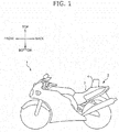
- FIG. 1 An appearance of the two-wheeled motor vehicle 1 on which the seat 2 according to this embodiment is mounted is shown in FIG. 1 . It can be considered that the two-wheeled motor vehicle 1 is configured as a general two-wheeled motor vehicle in points other than the seat 2 as shown in FIG. 1 .
- the seat 2 is a seat in a saddle shape on which an occupant (rider) seats in a straddle state, and is provided for the two-wheeled motor vehicle 1 in a detachable manner.
- attachment holes are formed in the two-wheeled motor vehicle 1, and the seat 2 is attached to the two-wheeled motor vehicle 1 through the attachment holes and fasteners.
- FIG. 2 A description will now be given of a configuration of the seat 2 referring to FIG. 2 .
- the seat 2 in such a state that a backrest 4 is attached to a seat main body 3 on which the occupant seats is shown in FIG. 2 . It should be noted that the backrest 4 can be detached from the seat main body 3 as described later.
- the seat main body 3 includes a seating portion 3a, an inclined portion 3b, and a back portion 3c in this sequence from a front portion as shown in FIG. 2 .
- the seating portion 3a serves as a surface for supporting the buttocks of the occupant.
- the inclined portion 3b serves as a surface for supporting the lumbar of the occupant. Specifically, the inclined portion 3b couples the seating portion 3a and the back portion 3c to each other, and forms a surface inclined obliquely backward from a back end of the seating portion 3a.
- the back portion 3c connects to the inclined portion 3b, and is provided at a position high in the top to bottom direction with respect to the seating portion 3a.
- the backrest 4 is detachably attached to the back portion 3c in this embodiment.
- the back portion 3c can also be used as a rear seat for tandem riding when the backrest 4 is detached from the seat main body 3.
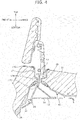
- a cushion member 21 is placed on a resin frame 26, and the cushion member 21 is further covered with a skin material in a thickness direction of the seat main body 3 as shown in FIG. 4 .
- a first protruded portion 50 is formed on a seat front portion
- a second protruded portion 51 is formed on a seat center portion
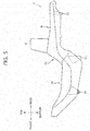
- a third protruded portion 52 is formed on a seat back portion on a bottom portion of the seat 2 as shown in FIG. 5 .
- the first protruded portion 50 is in a thick rib shape, and is provided below the seating portion 3a.
- the second protruded portion 51 is in a thick rib shape, and is provided below the inclined portion 3b.
- the third protruded portion 52 is in a conical shape (cone), and is provided below the back portion 3c.
- the first protruded portion 50, the second protruded portion 51, and the third protruded portion 52 are respectively provided in the seat front portion, the seat center portion, and the seat back portion in this way, and the seat 2 can thus be supported by the first protruded portion 50 and the second protruded portion 51 or the second protruded portion 51 and the third protruded portion 52.
- a rolled-in portion of the skin material of the seat 2 can be prevented from touching the ground, a work bench, or the like when the seat 2 is maintained.
- the third protruded portion 52 is formed into the conical shape, thereby providing effects in terms of suppression of an increase in the weight, an increase in rigidity, and an increase in productivity.
- the backrest 4 is attached to a front portion of the back portion 3c, and forms surfaces for supporting the lumbar and the back of the occupant in a state in which the occupant is seating on the seat main body 3.
- a backrest unit U which is formed by unifying the backrest 4, a support member 13, a stay portion 14, a first bracket 15, and a second bracket 16, is shown in FIG. 3 .
- a cross sectional view of the seat 2 along a center line in a seat widthwise direction of the seat 2 in a state in which the backrest 4 is attached is shown in FIG. 4 .
- the support member 13 is attached to a back portion of the backrest 4 as shown in FIG. 3 and FIG. 4 .
- a mechanism for adjusting a position and an angle of the backrest 4 may be provided at an attachment portion of the support member 13 and the backrest 4.
- the stay portion 14 extending downward is fixed to a bottom portion of the support member 13 through welding or fasteners.
- the stay portion 14 is attached to the seat main body 3 in state in which the stay portion 14 is passed through a through hole 19 formed in the top to bottom direction of the seat main body 3. Specifically, the stay portion 14 is fixed to the resin frame 26 of the seat main body 3 at attachment holes 14a formed in a bottom end portion through fasteners 18 such as bolts.
- weld nuts 14b are provided in the top to bottom direction on the stay portion 14, and the first bracket 15 extending backward from the stay portion 14 is fixed to the weld nuts 14b in a top portion through fasteners 18.
- the second bracket 16 extending backward from the stay portion 14 is fixed to the weld nuts 14b in a bottom portion of the stay portion 14 through the fastener 18.
- An engagement member 17 is fixed to the seat main body 3 in a state in which the engagement member 17 is inserted through the through hole 19 as shown in FIG. 4 .
- the engagement member 17 has a function of preventing water from entering into the skin material and the cushion member 21, and discharging the water accumulated on a surface of the seat main body 3 via the through hole 19 to a rear surface side.
- a flange portion 17A at a top end of the engagement member 17 is lathed on a top surface of the seat main body 3 as shown in FIG. 4 , FIG. 7 , and FIG. 9 .
- An inclined portion 17B inclined toward a center of the through hole 19 is provided at a center portion in the top to bottom direction of the engagement member 17.
- Bottom end portions 17C below the inclined portion 17B of the engagement member 17 branch toward the front and back directions of the seat 2. Then, the branching bottom end portions 17C of the engagement member 17 are respectively attached to a bottom surface of the seat main body 3 (resin frame 26) through fixing metal fittings 11 such as tacker needles or the like.
- the fasteners 18 are loosened on the bottom surface side of the seat 2, thereby detaching the first bracket 15 and the second bracket 16 from the stay portion 14.
- the unified body of the backrest 4, the support member 13, and the stay portion 14 can be detached from the seat main body 3 by pulling up the backrest 4 in the state described before.
- the state described before is a state in which the engagement member 17 and the through hole 19 are exposed on the top surface of the seat main body 3 as shown in FIG. 9 .
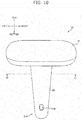
- a cover member 30 shown in FIG. 10 and FIG. 11 is fit to the engagement member 17, thereby closing the through hole 19 in the seat 2 according to this embodiment.
- the cover member 30 includes a lid portion 31 and a downward extension portion 32 downward extending from the lid portion 31 as shown in FIG. 10 and FIG. 11 .
- the lid portion 31 is in a flat plate shape in an approximately rectangular shape along an inner peripheral portion of the flange portion 17A of the engagement member 17.
- a top surface of the lid portion 31 may be slightly curved so as to smoothly connect to the top surface of the seat main body 3 when the cover member 30 is attached to the engagement member 17.
- a flange portion 31A is provided in an outer edge portion on the bottom surface of the lid portion 31 as shown in FIG. 11 .
- Multiple concave portions 31B are formed in the flange portion 31A.
- the multiple concave portions 31B are provided at positions respectively opposing multiple convex portions 17D provided inside with respect to the flange portion 17A of the engagement member 17. Then, the concave portions 31B formed in the flange portion 31A of the cover member 30 fit to the convex portions 17D of the engagement member 17 when the cover member 30 is attached to the engagement member 17.
- the downward extension portion 32 is a portion in a tongue shape downward extending from an approximately center portion of the bottom surface of the lid portion 31.
- a latch hole 32B for latching on a T-shape protrusion 40 of the resin frame 26 is formed in an end portion 32A on a bottom side of the downward extension portion 32.
- the latch hole 32B is a through hole in an approximately rectangular shape, and a taper is formed in a periphery of the latch hole 32B so that a thickness of the downward extension portion 32 gradually decreases toward the latch hole 32B.
- the lid portion 31 of the cover member 30 engages with a top end portion of the engagement member 17, and the convex portions 17D of the engagement member 17 enter into the concave portions 31B of the flange portion 31A of the lid portion 31 as shown in FIG. 7 . Consequently, backlash of the lid portion 31 of the cover member 30 when the cover member 30 is attached to the engagement member 17 can be prevented.
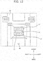
- the T-shape protrusion 40 protruding from the bottom surface of the resin frame 26 is formed on a seat back portion side with respect to the through hole 19 on the bottom surface of the resin frame 26 of the seat main body 3 as shown in FIG. 12 .
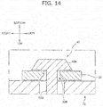
- the T-shape protrusion 40 is a protrusion in an approximately T shape including a top-to-bottom extension portion 40B extending in the top to bottom direction and a head portion 40A extending in a horizontal direction at a distal end of the top-to-bottom extension portion 40B as shown in FIG. 14 .
- a width of the head portion 40A is wider than a width of the top-to-bottom extension portion 40B.
- the downward extension portion 32 of the cover member 30 passes through the through hole 19, and is latched on the T-shape protrusion 40 formed on the bottom surface of the resin frame 26 as shown in FIG. 7 and FIG. 13 .
- the downward extension portion 32 is in a state curved toward the seat back portion.
- the downward extension portion 32 is latched on the T-shape protrusion 40 by inserting the head portion 40A of the T-shape protrusion 40 through the latch hole 32B formed in the end portion 32A in the tongue shape of the downward extension portion 32 as shown in FIG. 14 .
- the width of the latch hole 32B is narrower than the width of the head portion 40A, and is wider than the width of the top-to-bottom extension portion 40B.
- the downward extension portion 32 has elasticity, when the latch hole 32B is pressed over the head portion 40A in a state in which the latch hole 32B is passed over one side of the head portion 40A, the latch hole 32B elastically deforms, and widens, and the head portion 40A is consequently passed through the latch hole 32B.
- FIG. 15 A first variation of the cover member 30 is shown in FIG. 15 .
- the hole formed in the end portion 32A of the downward extension portion 32 of the cover member 30 may be a latch hole 32E constructed of a first opening portion 32C and a second opening portion 32D as shown in FIG. 15 .
- first opening portion 32C is wider in the width than the head portion 40A of the T-shape protrusion 40
- second opening portion 32D is narrower in the width than the head portion 40A of the T-shape protrusion 40.
- the end portion 32A of the downward extension portion 32 of the cover member 30 is latched on the T-shape protrusion 40 by passing the head portion 40A of the T-shape protrusion 40 through the first opening portion 32C, and then, sliding the head portion 40A toward the second opening portion 32D side.
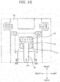
- a protruded portion 32F in a T shape may be provided in the downward extension portion 32, and a latch hole 41 in which the protruded portion 32F is latched may be provided on the bottom surface of the resin frame 26 as shown in FIG. 16 and FIG. 17 .
- the downward extension portion 32 is made of an elastically deformable material, and the protruded portion 32F of the downward extension portion 32 can be pushed into the latch hole 41.
- the protruded portion 32F can be prevented from being detached from the latch hole 41 by forming an entrance of the latch hole 41 to be narrower than a width of the protruded portion 32F.
- the end portion 32A of the downward extension portion 32 can be locked at the position remote from the seat surface of the seat 2 by forming the downward extension portion 32 into the tongue shape extending downward over a long distance in the seat 2.
- the downward extension portion 32 of the cover member 30 is deformable, and is locked in the curved state to the T-shape protrusion 40, and the attachment of the cover member 30 to the bottom surface of the seat main body 3 is facilitated in the seat 2.
- the mechanism of locking the cover member 30 to the bottom surface of the seat main body 3 can be realized as the simple structure by providing the T-shape protrusion 40 on the resin frame 26, and providing the latch hole 32B in which the T-shape protrusion 40 is latched on the downward extension portion 32 of the cover member 30 in the seat 2. Moreover, an operation of attaching the cover member 30 to the bottom surface of the seat main body 3 can also be simplified.
- the detachment of the end portion 32A of the downward extension portion 32 from the T-shape protrusion 40 can be suppressed by forming the width of the head portion 40A of the T-shape protrusion 40 to be wider than the width of the latch hole 32B in the seat 2.
- the backlash of the cover member 30 can be suppressed by forming the flange portion 31A on the outer periphery of the lid portion 31 of the cover member 30 in the seat 2.
- a position displacement of the cover member can be suppressed by forming the concave portions 31B in the flange portion 31A of the lid portion 31, and forming the convex portions 17D fit to the concave portions 31B on the engagement member 17 in the seat 2. Moreover, consequently, the backlash of the cover member 30 can further be suppressed.
- the bottom end portions 17C of the engagement member 17 can be spread by fixing the bottom end portions 17C of the engagement member 17 to the bottom surface of the resin frame 26 in the seat 2. Consequently, stick of the downward extension portion 32 of the cover member 30 to the bottom portion of the engagement member 17 can be suppressed.
- the spread of the bottom end portions 17C of the engagement member 17 promotes the downward discharge of the water from the engagement member 17.
- the mechanism for locking the cover member 30 to the bottom surface of the seat main body 3 can be realized as the simple structure by forming the protruded portion 32F on the downward extension portion 32, and forming the latch hole 41 on the bottom surface of the resin frame 26 in the seat 2. Moreover, workability of the attachment of the cover member to the bottom surface of the seat main body can also be increased. Moreover, the operation of attaching the cover member 30 to the bottom surface of the seat main body 3 is also simplified.
- the straddle-type seat according to the present invention can be applied to a seat not only for the two-wheeled motor vehicle, but also for a motor vehicle, a ship, an airplane, and the like.
- the component attached to the through hole 19 is not limited to the backrest 4, and may be a storage box and the like.
- multiple through holes 19 may be formed in the seat main body 3, and the cover member 30 may be attached to each thereof.
Landscapes
- Engineering & Computer Science (AREA)
- Mechanical Engineering (AREA)
- Seats For Vehicles (AREA)
Abstract
Description
- The present invention relates to a straddle-type seat and a cover member, and more particularly to a straddle-type seat capable of preventing a cover member from being detached, and increasing a crime prevention property and a cover member.
- A conveyance such as a two-wheeled motor vehicle employs a straddle-type seat on which an occupant seats in a straddle state. As this straddle-type seat, as described in
JP5723714B2 - Incidentally, if a hole for attaching a detachable component is provided in a seating portion of the seat, and a cover member for closing the hole in a state in which the component is detached is formed into a simple lid shape, there poses such a problem that the cover member is detached when an occupant gets on and off or impact is applied.
- Moreover, if the cover member takes the simple lid shape, there is a room for an increase in the crime prevention property.
- The present invention has been made in view of the above-described problems, and has an object to provide a straddle-type seat capable of preventing a cover member for closing a through hole formed on a seat surface from being detached, and increasing the crime prevention property and a cover member.
- The problems described before are solved by a straddle-type vehicle seat according to the present invention, the straddle-type seat on which an occupant seats in a straddle state includes a seat main body on which an occupant seats, and a cover member that covers a through hole formed in the seat main body, the cover member includes a lid portion that closes the through hole on a top surface of the seat main body, and a downward extension portion that downward extends from the lid portion, and the downward extension portion is locked to a lock portion formed on a bottom surface of the seat main body.
- Moreover, the problems described before are solved by a cover member according to the present invention, the cover member attached to a seat main body in which a through hole is formed in a straddle-type seat on which an occupant seats in a straddle state includes a lid portion that closes the through hole on a top surface of the seat main body, and a downward extension portion that downward extends from the lid portion, and the downward extension portion is locked to a lock portion formed on a bottom surface of the seat main body.
- With the straddle-type seat and the cover member, the cover member can surely be attached by locking the downward extension portion that downward extends from the lid portion of the cover member for closing the through hole formed on the seat surface to the bottom surface of the seat main body. Consequently, the cover member can be prevented from being detached, and the crime prevention property can be increased.
- Moreover, in the above-mentioned straddle-type seat, preferably, the downward extension portion is in a tongue shape, and an end portion of the downward extension portion is locked to the lock portion.
- With this configuration, the cover member can be locked to the seat main body at the position remote from the seat surface. Consequently, it is difficult to detach the cover member in a state in which the seat is not detached from the vehicle.
- Moreover, in the above-mentioned straddle-type seat, preferably, the downward extension portion is deformable, and is locked to the lock portion in a curved state.
- With this configuration, workability when the cover member is attached to the bottom surface of the seat main body can be increased.
- Moreover, in the above-mentioned straddle-type seat, preferably, the lock portion is a protrusion, and a latch hole in which the protrusion is latched is formed in the downward extension portion.
- With this configuration, the mechanism for locking the cover member to the bottom surface of the seat main body can be realized as the simple structure. Moreover, an operation of attaching the cover member to the bottom surface of the seat main body is simplified.
- Moreover, in the above-mentioned straddle-type seat, preferably, the protrusion is in a T shape, and a width of a head portion of the protrusion is wider than a width of the latch hole.
- With this configuration, the cover member can be prevented from being detached from the lock portion.
- Moreover, in the above-mentioned straddle-type seat, preferably, a flange portion is formed on an outer periphery of the lid portion.
- With this configuration, backlash of the cover member can be suppressed.
- Moreover, the above-mentioned straddle-type seat, preferably, further includes an engagement member that is fixed in a state in which the engagement member is inserted into the through hole of the seat main body, and engages with the cover member, a concave portion is formed in the flange portion, and the engagement member includes a convex portion fit to the concave portion of the flange portion.
- With this configuration, a displacement of the cover member can be suppressed. Moreover, the backlash of the cover member can further be suppressed.
- Moreover, in the above-mentioned straddle-type seat, preferably, the engagement member further includes an inclined portion inclined toward a center of the through hole.
- With this configuration, water is easily discharged from the engagement member via the through hole. Consequently, accumulation of the water in the engagement member can be suppressed.
- Moreover, in the above-mentioned straddle-type seat, preferably, a bottom end portion of the engagement member is fixed to the bottom surface of the seat main body.
- With this configuration, a bottom portion of the engagement member can be spread. Consequently, the downward extension portion of the cover member is easily passed through the bottom portion of the engagement member.
- Moreover, the spread of the bottom portion of the engagement member promotes the downward discharge of the water from the engagement member.
- Moreover, in the above-mentioned straddle-type seat, preferably, the downward extension portion comprises a protruded portion formed on an end portion, and a latch hole in which the protruded portion is latched is formed in the lock portion.
- With this configuration, the mechanism for locking the cover member to the bottom surface of the seat main body can be realized as the simple structure. Moreover, the operation when the cover member is attached to the bottom surface of the seat main body is simplified.
- According to the present invention, the cover member can be prevented from being detached, and the crime prevention property can be increased.
- According to the present invention, the cover member can be locked to the seat main body at the position remote from the seat surface.
- According to the present invention, the workability when the cover member is attached to the bottom surface of the seat main body can be increased.
- According to the present invention, the operation of attaching the cover member to the bottom surface of the seat main body is simplified.
- According to the present invention, the cover member can be prevented from being detached from the lock portion.
- According to the present invention, the backlash of the cover member can be suppressed.
- According to the present invention, the displacement of the cover member can be suppressed.
- According to the present invention, the water is easily discharged from the engagement member via the through hole.
- According to the present invention, the downward extension portion of the cover member is easily passed through the bottom portion of the engagement member.
- According to the present invention, the mechanism for locking the cover member to the bottom surface of the seat main body can be realized as the simple structure.
-
-
FIG. 1 is a diagram of a two-wheeled motor vehicle on which a seat according to an embodiment is mounted. -
FIG. 2 is a perspective view of the seat in a state in which a backrest is attached. -
FIG. 3 is a front view of a backrest unit. -
FIG. 4 is a cross sectional view made on a plane and in a direction indicated by arrows IV in a neighborhood of the backrest inFIG. 2 . -
FIG. 5 is a side view of the seat. -
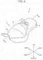
FIG. 6 is a perspective view of the seat in a state in which a cover member is attached. -
FIG. 7 is a cross sectional view made on a plane and in a direction indicated by arrows VII in a neighborhood of the cover member inFIG. 6 . -
FIG. 8 is a top view of the neighborhood of the cover member inFIG. 6 . -
FIG. 9 is a top view in a state in which the cover member is detached. -
FIG. 10 is a top perspective view of the cover member. -
FIG. 11 is a cross sectional view made on a plane and in a direction indicated by XI inFIG. 10 . -
FIG. 12 is a bottom view of a periphery of a through hole in the state in which the cover member is detached. -
FIG. 13 is a bottom view of the periphery of the through hole in the state in which the cover member is attached. -
FIG. 14 is a cross sectional view made on a plane and in a direction indicated by arrows XIV in a periphery of the cover member and a lock portion of a resin frame inFIG. 13 . -
FIG. 15 is a view of a shape of an end portion of the cover member according to a first variation. -
FIG. 16 is a bottom view in a state in which the cover member according to a second variation is attached. -
FIG. 17 is a cross sectional view made on a plane and in a direction indicated by arrows XVII in a periphery of the cover member and the lock portion of the resin frame inFIG. 16 . - A description will now be given of a seat 2 (an example of a straddle-type seat) according to an embodiment (hereinafter referred to as this embodiment) of the present invention referring to
FIG. 1 to FIG. 17 . It should be noted that thought theseat 2 according to this embodiment is an example in which the straddle-type seat according to the present invention is applied to a seat for a two-wheeled motor vehicle, theseat 2 is simply an example for promoting understanding of the present invention, and does not limit the present invention. In other words, it should be understood that the shapes, dimensions, arrangements, and the like described herein can be changed or improved without departing from the purport of the present invention, and equivalents thereof are included in the present invention. - Moreover, it is assumed that respective directions, which are a front to back direction, a right and left direction, and a top to bottom direction, coincide with respective directions viewed from a seating person on the
seat 2 hereinafter. - An appearance of the two-wheeled
motor vehicle 1 on which theseat 2 according to this embodiment is mounted is shown inFIG. 1 . It can be considered that the two-wheeledmotor vehicle 1 is configured as a general two-wheeled motor vehicle in points other than theseat 2 as shown inFIG. 1 . - It should be noted that the
seat 2 is a seat in a saddle shape on which an occupant (rider) seats in a straddle state, and is provided for the two-wheeledmotor vehicle 1 in a detachable manner. Specifically, attachment holes, not shown, are formed in the two-wheeledmotor vehicle 1, and theseat 2 is attached to the two-wheeledmotor vehicle 1 through the attachment holes and fasteners. - A description will now be given of a configuration of the
seat 2 referring toFIG. 2 . Theseat 2 in such a state that abackrest 4 is attached to a seatmain body 3 on which the occupant seats is shown inFIG. 2 . It should be noted that thebackrest 4 can be detached from the seatmain body 3 as described later. - The seat
main body 3 includes aseating portion 3a, aninclined portion 3b, and aback portion 3c in this sequence from a front portion as shown inFIG. 2 . - The
seating portion 3a serves as a surface for supporting the buttocks of the occupant. - The
inclined portion 3b serves as a surface for supporting the lumbar of the occupant. Specifically, theinclined portion 3b couples theseating portion 3a and theback portion 3c to each other, and forms a surface inclined obliquely backward from a back end of theseating portion 3a. - The
back portion 3c connects to theinclined portion 3b, and is provided at a position high in the top to bottom direction with respect to theseating portion 3a. Thebackrest 4 is detachably attached to theback portion 3c in this embodiment. For example, theback portion 3c can also be used as a rear seat for tandem riding when thebackrest 4 is detached from the seatmain body 3. - Moreover, a
cushion member 21 is placed on aresin frame 26, and thecushion member 21 is further covered with a skin material in a thickness direction of the seatmain body 3 as shown inFIG. 4 . - Moreover, a first protruded
portion 50 is formed on a seat front portion, a second protrudedportion 51 is formed on a seat center portion, and a third protrudedportion 52 is formed on a seat back portion on a bottom portion of theseat 2 as shown inFIG. 5 . - The first protruded
portion 50 is in a thick rib shape, and is provided below theseating portion 3a. - The second protruded
portion 51 is in a thick rib shape, and is provided below theinclined portion 3b. - The third protruded
portion 52 is in a conical shape (cone), and is provided below theback portion 3c. - The first protruded
portion 50, the second protrudedportion 51, and the third protrudedportion 52 are respectively provided in the seat front portion, the seat center portion, and the seat back portion in this way, and theseat 2 can thus be supported by the first protrudedportion 50 and the second protrudedportion 51 or the second protrudedportion 51 and the third protrudedportion 52. - Therefore, a rolled-in portion of the skin material of the
seat 2 can be prevented from touching the ground, a work bench, or the like when theseat 2 is maintained. - It should be noted that the third protruded
portion 52 is formed into the conical shape, thereby providing effects in terms of suppression of an increase in the weight, an increase in rigidity, and an increase in productivity. - The
backrest 4 is attached to a front portion of theback portion 3c, and forms surfaces for supporting the lumbar and the back of the occupant in a state in which the occupant is seating on the seatmain body 3. - A backrest unit U, which is formed by unifying the
backrest 4, asupport member 13, astay portion 14, afirst bracket 15, and asecond bracket 16, is shown inFIG. 3 . Moreover, a cross sectional view of theseat 2 along a center line in a seat widthwise direction of theseat 2 in a state in which thebackrest 4 is attached is shown inFIG. 4 . - The
support member 13 is attached to a back portion of thebackrest 4 as shown inFIG. 3 andFIG. 4 . - It should be noted that a mechanism for adjusting a position and an angle of the
backrest 4 may be provided at an attachment portion of thesupport member 13 and thebackrest 4. - The
stay portion 14 extending downward is fixed to a bottom portion of thesupport member 13 through welding or fasteners. - The
stay portion 14 is attached to the seatmain body 3 in state in which thestay portion 14 is passed through a throughhole 19 formed in the top to bottom direction of the seatmain body 3. Specifically, thestay portion 14 is fixed to theresin frame 26 of the seatmain body 3 atattachment holes 14a formed in a bottom end portion throughfasteners 18 such as bolts. - Multiple weld nuts 14b are provided in the top to bottom direction on the
stay portion 14, and thefirst bracket 15 extending backward from thestay portion 14 is fixed to the weld nuts 14b in a top portion throughfasteners 18. - Moreover, the
second bracket 16 extending backward from thestay portion 14 is fixed to the weld nuts 14b in a bottom portion of thestay portion 14 through thefastener 18. - On this occasion, back end portions of the
first bracket 15 and thesecond bracket 16 are fixed to theresin frame 26 through thefasteners 18. - It should be noted that it may be assumed that the
second bracket 16 is fixed to theresin frame 26 through thefasteners 18 atattachment holes 16a of thesecond bracket 16. - An
engagement member 17 is fixed to the seatmain body 3 in a state in which theengagement member 17 is inserted through the throughhole 19 as shown inFIG. 4 . - The
engagement member 17 has a function of preventing water from entering into the skin material and thecushion member 21, and discharging the water accumulated on a surface of the seatmain body 3 via the throughhole 19 to a rear surface side. - A
flange portion 17A at a top end of theengagement member 17 is lathed on a top surface of the seatmain body 3 as shown inFIG. 4 ,FIG. 7 , andFIG. 9 . - An
inclined portion 17B inclined toward a center of the throughhole 19 is provided at a center portion in the top to bottom direction of theengagement member 17. -
Bottom end portions 17C below theinclined portion 17B of theengagement member 17 branch toward the front and back directions of theseat 2. Then, the branchingbottom end portions 17C of theengagement member 17 are respectively attached to a bottom surface of the seat main body 3 (resin frame 26) through fixingmetal fittings 11 such as tacker needles or the like. - It should be noted that the
backrest 4 is detached in the following sequence. - First, after the
seat 2 is detached from the two-wheeledmotor vehicle 1, thefasteners 18 are loosened on the bottom surface side of theseat 2, thereby detaching thefirst bracket 15 and thesecond bracket 16 from thestay portion 14. - Then, the unified body of the
backrest 4, thesupport member 13, and thestay portion 14 can be detached from the seatmain body 3 by pulling up thebackrest 4 in the state described before. - It should be noted that the state described before is a state in which the
engagement member 17 and the throughhole 19 are exposed on the top surface of the seatmain body 3 as shown inFIG. 9 . - Thus, a
cover member 30 shown inFIG. 10 andFIG. 11 is fit to theengagement member 17, thereby closing the throughhole 19 in theseat 2 according to this embodiment. - It should be noted that the state in which the
cover member 30 is attached to the seatmain body 3 is shown inFIG. 6 andFIG. 8 . - A description will now be given of a configuration of the
cover member 30. - The
cover member 30 includes alid portion 31 and adownward extension portion 32 downward extending from thelid portion 31 as shown inFIG. 10 andFIG. 11 . - The
lid portion 31 is in a flat plate shape in an approximately rectangular shape along an inner peripheral portion of theflange portion 17A of theengagement member 17. - It should be noted that a top surface of the
lid portion 31 may be slightly curved so as to smoothly connect to the top surface of the seatmain body 3 when thecover member 30 is attached to theengagement member 17. - Moreover, a
flange portion 31A is provided in an outer edge portion on the bottom surface of thelid portion 31 as shown inFIG. 11 . Multipleconcave portions 31B are formed in theflange portion 31A. - The multiple
concave portions 31B are provided at positions respectively opposing multipleconvex portions 17D provided inside with respect to theflange portion 17A of theengagement member 17. Then, theconcave portions 31B formed in theflange portion 31A of thecover member 30 fit to theconvex portions 17D of theengagement member 17 when thecover member 30 is attached to theengagement member 17. - Moreover, the
downward extension portion 32 is a portion in a tongue shape downward extending from an approximately center portion of the bottom surface of thelid portion 31. Alatch hole 32B for latching on a T-shape protrusion 40 of theresin frame 26 is formed in anend portion 32A on a bottom side of thedownward extension portion 32. - The
latch hole 32B is a through hole in an approximately rectangular shape, and a taper is formed in a periphery of thelatch hole 32B so that a thickness of thedownward extension portion 32 gradually decreases toward thelatch hole 32B. - Moreover, a description will now be given of an attachment structure of the
cover member 30 to the seatmain body 3 referring toFIG. 7 . - The
lid portion 31 of thecover member 30 engages with a top end portion of theengagement member 17, and theconvex portions 17D of theengagement member 17 enter into theconcave portions 31B of theflange portion 31A of thelid portion 31 as shown inFIG. 7 . Consequently, backlash of thelid portion 31 of thecover member 30 when thecover member 30 is attached to theengagement member 17 can be prevented. - Moreover, the T-
shape protrusion 40 protruding from the bottom surface of theresin frame 26 is formed on a seat back portion side with respect to the throughhole 19 on the bottom surface of theresin frame 26 of the seatmain body 3 as shown inFIG. 12 . - The T-
shape protrusion 40 is a protrusion in an approximately T shape including a top-to-bottom extension portion 40B extending in the top to bottom direction and ahead portion 40A extending in a horizontal direction at a distal end of the top-to-bottom extension portion 40B as shown inFIG. 14 . On this occasion, a width of thehead portion 40A is wider than a width of the top-to-bottom extension portion 40B. - Then, the
downward extension portion 32 of thecover member 30 passes through the throughhole 19, and is latched on the T-shape protrusion 40 formed on the bottom surface of theresin frame 26 as shown inFIG. 7 andFIG. 13 . On this occasion, thedownward extension portion 32 is in a state curved toward the seat back portion. - Specifically, the
downward extension portion 32 is latched on the T-shape protrusion 40 by inserting thehead portion 40A of the T-shape protrusion 40 through thelatch hole 32B formed in theend portion 32A in the tongue shape of thedownward extension portion 32 as shown inFIG. 14 . - It should be noted that the width of the
latch hole 32B is narrower than the width of thehead portion 40A, and is wider than the width of the top-to-bottom extension portion 40B. With this configuration, after theend portion 32A of thedownward extension portion 32 is latched on the T-shape protrusion 40, theend portion 32A is less likely detached from the T-shape protrusion 40. - It should be noted that the
downward extension portion 32 has elasticity, when thelatch hole 32B is pressed over thehead portion 40A in a state in which thelatch hole 32B is passed over one side of thehead portion 40A, thelatch hole 32B elastically deforms, and widens, and thehead portion 40A is consequently passed through thelatch hole 32B. - Moreover, the present invention is not limited to the above-mentioned embodiment. A description will now be given of variations of the
cover member 30. - A first variation of the
cover member 30 is shown inFIG. 15 . The hole formed in theend portion 32A of thedownward extension portion 32 of thecover member 30 may be alatch hole 32E constructed of afirst opening portion 32C and asecond opening portion 32D as shown inFIG. 15 . - It should be noted that the
first opening portion 32C is wider in the width than thehead portion 40A of the T-shape protrusion 40, and thesecond opening portion 32D is narrower in the width than thehead portion 40A of the T-shape protrusion 40. - Then, the
end portion 32A of thedownward extension portion 32 of thecover member 30 is latched on the T-shape protrusion 40 by passing thehead portion 40A of the T-shape protrusion 40 through thefirst opening portion 32C, and then, sliding thehead portion 40A toward thesecond opening portion 32D side. - Moreover, a protruded
portion 32F in a T shape may be provided in thedownward extension portion 32, and alatch hole 41 in which the protrudedportion 32F is latched may be provided on the bottom surface of theresin frame 26 as shown inFIG. 16 andFIG. 17 . - On this occasion, the
downward extension portion 32 is made of an elastically deformable material, and the protrudedportion 32F of thedownward extension portion 32 can be pushed into thelatch hole 41. On this occasion, the protrudedportion 32F can be prevented from being detached from thelatch hole 41 by forming an entrance of thelatch hole 41 to be narrower than a width of the protrudedportion 32F. - With the
seat 2 described before, easy detachment of thecover member 30 can be suppressed by locking thedownward extension portion 32 extending downward from thelid portion 31 of thecover member 30 for closing the throughhole 19 formed in the seatmain body 3 to the T-shape protrusion 40 on the bottom surface of the seatmain body 3. As a result, thecover member 30 can be prevented from being detached, and crime prevention property can be increased. - Moreover, the
end portion 32A of thedownward extension portion 32 can be locked at the position remote from the seat surface of theseat 2 by forming thedownward extension portion 32 into the tongue shape extending downward over a long distance in theseat 2. - Consequently, it is difficult to detach the
cover member 30 in the state in which theseat 2 is not detached from the two-wheeledmotor vehicle 1. - Moreover, the
downward extension portion 32 of thecover member 30 is deformable, and is locked in the curved state to the T-shape protrusion 40, and the attachment of thecover member 30 to the bottom surface of the seatmain body 3 is facilitated in theseat 2. - Moreover, the mechanism of locking the
cover member 30 to the bottom surface of the seatmain body 3 can be realized as the simple structure by providing the T-shape protrusion 40 on theresin frame 26, and providing thelatch hole 32B in which the T-shape protrusion 40 is latched on thedownward extension portion 32 of thecover member 30 in theseat 2. Moreover, an operation of attaching thecover member 30 to the bottom surface of the seatmain body 3 can also be simplified. - Moreover, the detachment of the
end portion 32A of thedownward extension portion 32 from the T-shape protrusion 40 can be suppressed by forming the width of thehead portion 40A of the T-shape protrusion 40 to be wider than the width of thelatch hole 32B in theseat 2. - Moreover, the backlash of the
cover member 30 can be suppressed by forming theflange portion 31A on the outer periphery of thelid portion 31 of thecover member 30 in theseat 2. - Moreover, a position displacement of the cover member can be suppressed by forming the
concave portions 31B in theflange portion 31A of thelid portion 31, and forming theconvex portions 17D fit to theconcave portions 31B on theengagement member 17 in theseat 2. Moreover, consequently, the backlash of thecover member 30 can further be suppressed. - Moreover, the discharge of the water from the
engagement member 17 via the throughhole 19 is promoted by theengagement member 17 having theinclined portion 17B inclined toward the center of the throughhole 19 in theseat 2. Consequently, the accumulation of the water in theengagement member 17 can be suppressed. - Moreover, the
bottom end portions 17C of theengagement member 17 can be spread by fixing thebottom end portions 17C of theengagement member 17 to the bottom surface of theresin frame 26 in theseat 2. Consequently, stick of thedownward extension portion 32 of thecover member 30 to the bottom portion of theengagement member 17 can be suppressed. - Moreover, the spread of the
bottom end portions 17C of theengagement member 17 promotes the downward discharge of the water from theengagement member 17. - Moreover, the mechanism for locking the
cover member 30 to the bottom surface of the seatmain body 3 can be realized as the simple structure by forming the protrudedportion 32F on thedownward extension portion 32, and forming thelatch hole 41 on the bottom surface of theresin frame 26 in theseat 2. Moreover, workability of the attachment of the cover member to the bottom surface of the seat main body can also be increased. Moreover, the operation of attaching thecover member 30 to the bottom surface of the seatmain body 3 is also simplified. - Moreover, the straddle-type seat according to the present invention can be applied to a seat not only for the two-wheeled motor vehicle, but also for a motor vehicle, a ship, an airplane, and the like.
- The component attached to the through
hole 19 is not limited to thebackrest 4, and may be a storage box and the like. - Moreover, multiple through
holes 19 may be formed in the seatmain body 3, and thecover member 30 may be attached to each thereof. -
- 1: two-wheeled motor vehicle
- 2: seat (straddle-type seat)
- 3: seat main body
- 3a: seating portion
- 3b: inclined portion
- 3c: back portion
- 4: backrest
- 11: fixing metal fitting
- 13: support member
- 14: stay portion
- 14a: attachment hole
- 14b: weld nut
- 15: first bracket
- 16: second bracket
- 16a: attachment hole
- 17: engagement member
- 17A: flange portion
- 17B: inclined portion
- 17C: bottom end portion
- 17D: convex portion
- 18: fastener
- 19: through hole
- 21: cushion member
- 26: resin frame
- 30: cover member
- 31: lid portion
- 31A: flange portion
- 31B: concave portion
- 32: downward extension portion
- 32A: end portion
- 32B: latch hole
- 32C: first opening portion
- 32D: second opening portion
- 32E: latch hole
- 32F: protruded portion
- 40: T-shape protrusion (lock portion)
- 40A: head portion
- 40B: top-to-bottom extension portion
- 41: latch hole
- 50: first protruded portion
- 51: second protruded portion
- 52: third protruded portion
- U: backrest unit
Claims (11)
- A straddle-type seat on which an occupant seats in a straddle state comprising:a seat main body on which an occupant seats; anda cover member that covers a through hole formed in the seat main body, characterized in that:the cover member comprises:a lid portion that closes the through hole on a top surface of the seat main body; anda downward extension portion that downward extends from the lid portion; andthe downward extension portion is locked to a lock portion formed on a bottom surface of the seat main body.
- The straddle-type seat according to claim 1, characterized in that:the downward extension portion is in a tongue shape; andan end portion of the downward extension portion is locked to the lock portion.
- The straddle-type seat according to claim 1 or 2, characterized in that the downward extension portion is deformable, and is locked to the lock portion in a curved state.
- The straddle-type seat according to any one of claims 1 to 3, characterized in that:the lock portion is a protrusion; anda latch hole in which the protrusion is latched is formed in the downward extension portion.
- The straddle-type seat according to claim 4, characterized in that:the protrusion is in a T shape; anda width of a head portion of the protrusion is wider than a width of the latch hole.
- The straddle-type seat according to any one of claims 1 to 5, characterized in that a flange portion is formed on an outer periphery of the lid portion.
- The straddle-type seat according to claim 6, further comprising an engagement member that is fixed in a state in which the engagement member is inserted into the through hole of the seat main body, and engages with the cover member, characterized in that:a concave portion is formed in the flange portion; andthe engagement member comprises a convex portion fit to the concave portion of the flange portion.
- The straddle-type seat according to claim 7, characterized in that the engagement member further comprises an inclined portion inclined toward a center of the through hole.
- The straddle-type seat according to claim 7 or 8, characterized in that a bottom end portion of the engagement member is fixed to the bottom surface of the seat main body.
- The straddle-type seat according to claim 1, characterized in that:the downward extension portion comprises a protruded portion formed on an end portion; anda latch hole in which the protruded portion is latched is formed in the lock portion.
- A cover member attached to a seat main body in which a through hole is formed in a straddle-type seat on which an occupant seats in a straddle state comprising:a lid portion that closes the through hole on a top surface of the seat main body; anda downward extension portion that downward extends from the lid portion, characterized in that the downward extension portion is locked to a lock portion formed on a bottom surface of the seat main body.
Applications Claiming Priority (1)
| Application Number | Priority Date | Filing Date | Title |
|---|---|---|---|
| JP2017059438A JP6527188B2 (en) | 2017-03-24 | 2017-03-24 | Cross seat type seat and cover member |
Publications (2)
| Publication Number | Publication Date |
|---|---|
| EP3378744A1 true EP3378744A1 (en) | 2018-09-26 |
| EP3378744B1 EP3378744B1 (en) | 2019-10-09 |
Family
ID=61763788
Family Applications (1)
| Application Number | Title | Priority Date | Filing Date |
|---|---|---|---|
| EP18163046.8A Active EP3378744B1 (en) | 2017-03-24 | 2018-03-21 | Straddle-type seat and cover member |
Country Status (3)
| Country | Link |
|---|---|
| US (1) | US10745073B2 (en) |
| EP (1) | EP3378744B1 (en) |
| JP (1) | JP6527188B2 (en) |
Citations (6)
| Publication number | Priority date | Publication date | Assignee | Title |
|---|---|---|---|---|
| JPS5723714B2 (en) | 1977-07-08 | 1982-05-20 | ||
| JPS5849564A (en) * | 1981-09-19 | 1983-03-23 | 本田技研工業株式会社 | Waterproof method for seat |
| US5214811A (en) * | 1992-07-09 | 1993-06-01 | Milsco Manufacturing Company | Watertight upholstery button |
| US5544937A (en) * | 1995-01-25 | 1996-08-13 | Hanagan; Michael W. | Motorcycle seat and method of making same |
| US7065809B1 (en) * | 2003-05-07 | 2006-06-27 | Milsco Manufacturing Company | Recessed cushion ornament |
| CN101380981A (en) * | 2007-09-07 | 2009-03-11 | 光阳工业股份有限公司 | Combined motorcycle back cushion capable of being shared by front seat and rear seat |
Family Cites Families (3)
| Publication number | Priority date | Publication date | Assignee | Title |
|---|---|---|---|---|
| JPH0334157Y2 (en) * | 1985-08-27 | 1991-07-19 | ||
| JP5723714B2 (en) | 2011-08-03 | 2015-05-27 | 本田技研工業株式会社 | Saddle riding vehicle |
| JP6933793B2 (en) | 2016-11-21 | 2021-09-08 | テイ・エス テック株式会社 | Straddle seat |
-
2017
- 2017-03-24 JP JP2017059438A patent/JP6527188B2/en active Active
-
2018
- 2018-03-21 EP EP18163046.8A patent/EP3378744B1/en active Active
- 2018-03-23 US US15/933,651 patent/US10745073B2/en active Active
Patent Citations (6)
| Publication number | Priority date | Publication date | Assignee | Title |
|---|---|---|---|---|
| JPS5723714B2 (en) | 1977-07-08 | 1982-05-20 | ||
| JPS5849564A (en) * | 1981-09-19 | 1983-03-23 | 本田技研工業株式会社 | Waterproof method for seat |
| US5214811A (en) * | 1992-07-09 | 1993-06-01 | Milsco Manufacturing Company | Watertight upholstery button |
| US5544937A (en) * | 1995-01-25 | 1996-08-13 | Hanagan; Michael W. | Motorcycle seat and method of making same |
| US7065809B1 (en) * | 2003-05-07 | 2006-06-27 | Milsco Manufacturing Company | Recessed cushion ornament |
| CN101380981A (en) * | 2007-09-07 | 2009-03-11 | 光阳工业股份有限公司 | Combined motorcycle back cushion capable of being shared by front seat and rear seat |
Also Published As
| Publication number | Publication date |
|---|---|
| JP2018161930A (en) | 2018-10-18 |
| US10745073B2 (en) | 2020-08-18 |
| EP3378744B1 (en) | 2019-10-09 |
| JP6527188B2 (en) | 2019-06-05 |
| US20180273125A1 (en) | 2018-09-27 |
Similar Documents
| Publication | Publication Date | Title |
|---|---|---|
| US8651525B2 (en) | Utility vehicle | |
| US20180281645A1 (en) | Vehicle seat | |
| US9981583B2 (en) | Vehicle seat | |
| JP7473827B2 (en) | Vehicle seat | |
| US8047615B2 (en) | Seat belt system and seat | |
| US10752204B2 (en) | Vehicle seat | |
| US20110175386A1 (en) | Mounting structure for a pillar garnish | |
| EP3378744B1 (en) | Straddle-type seat and cover member | |
| US10189386B2 (en) | Seat belt cover | |
| US10525930B2 (en) | Shoulder belt guide for a vehicle seating assembly | |
| US10625801B2 (en) | Straddle type seat | |
| JP5640679B2 (en) | Seat belt anchor mounting structure | |
| JP2012111409A (en) | Belt buckle drop prevention structure of seat belt | |
| EP2687402B1 (en) | Headrest device for a motor vehicle seat | |
| JP2019073150A (en) | Shoulder anchor | |
| JP2016132279A (en) | Vehicle seat | |
| KR101434804B1 (en) | Net hook for automotive luggage | |
| JP2015003579A (en) | Seat cover fix structure for vehicle seat | |
| FR2612471A1 (en) | Child seat equipped with a seatbelt and fixed removably in a motor vehicle | |
| US20180251176A1 (en) | Conveyance seat | |
| EP2208636B1 (en) | Vehicle seat with holding element to prevent the strap of a seatbelt from concealing an anchoring element | |
| JP2020006882A (en) | Vehicle seat | |
| JP7043709B2 (en) | Buckle device and buckle device mounting structure | |
| JP6743523B2 (en) | Vehicle seat | |
| JP2008296656A (en) | Seat cushion structure for flip-up type rear seat |
Legal Events
| Date | Code | Title | Description |
|---|---|---|---|
| PUAI | Public reference made under article 153(3) epc to a published international application that has entered the european phase |
Free format text: ORIGINAL CODE: 0009012 |
|
| STAA | Information on the status of an ep patent application or granted ep patent |
Free format text: STATUS: REQUEST FOR EXAMINATION WAS MADE |
|
| 17P | Request for examination filed |
Effective date: 20180321 |
|
| AK | Designated contracting states |
Kind code of ref document: A1 Designated state(s): AL AT BE BG CH CY CZ DE DK EE ES FI FR GB GR HR HU IE IS IT LI LT LU LV MC MK MT NL NO PL PT RO RS SE SI SK SM TR |
|
| AX | Request for extension of the european patent |
Extension state: BA ME |
|
| RBV | Designated contracting states (corrected) |
Designated state(s): AL AT BE BG CH CY CZ DE DK EE ES FI FR GB GR HR HU IE IS IT LI LT LU LV MC MK MT NL NO PL PT RO RS SE SI SK SM TR |
|
| GRAP | Despatch of communication of intention to grant a patent |
Free format text: ORIGINAL CODE: EPIDOSNIGR1 |
|
| STAA | Information on the status of an ep patent application or granted ep patent |
Free format text: STATUS: GRANT OF PATENT IS INTENDED |
|
| RIC1 | Information provided on ipc code assigned before grant |
Ipc: B62J 1/12 20060101ALI20190404BHEP Ipc: B62J 1/28 20060101ALI20190404BHEP Ipc: B62J 1/20 20060101AFI20190404BHEP |
|
| INTG | Intention to grant announced |
Effective date: 20190506 |
|
| GRAS | Grant fee paid |
Free format text: ORIGINAL CODE: EPIDOSNIGR3 |
|
| GRAA | (expected) grant |
Free format text: ORIGINAL CODE: 0009210 |
|
| STAA | Information on the status of an ep patent application or granted ep patent |
Free format text: STATUS: THE PATENT HAS BEEN GRANTED |
|
| AK | Designated contracting states |
Kind code of ref document: B1 Designated state(s): AL AT BE BG CH CY CZ DE DK EE ES FI FR GB GR HR HU IE IS IT LI LT LU LV MC MK MT NL NO PL PT RO RS SE SI SK SM TR |
|
| REG | Reference to a national code |
Ref country code: GB Ref legal event code: FG4D |
|
| REG | Reference to a national code |
Ref country code: CH Ref legal event code: EP |
|
| REG | Reference to a national code |
Ref country code: IE Ref legal event code: FG4D |
|
| REG | Reference to a national code |
Ref country code: DE Ref legal event code: R096 Ref document number: 602018000822 Country of ref document: DE |
|
| REG | Reference to a national code |
Ref country code: AT Ref legal event code: REF Ref document number: 1188480 Country of ref document: AT Kind code of ref document: T Effective date: 20191115 |
|
| REG | Reference to a national code |
Ref country code: NL Ref legal event code: MP Effective date: 20191009 |
|
| REG | Reference to a national code |
Ref country code: LT Ref legal event code: MG4D |
|
| REG | Reference to a national code |
Ref country code: AT Ref legal event code: MK05 Ref document number: 1188480 Country of ref document: AT Kind code of ref document: T Effective date: 20191009 |
|
| PG25 | Lapsed in a contracting state [announced via postgrant information from national office to epo] |
Ref country code: BG Free format text: LAPSE BECAUSE OF FAILURE TO SUBMIT A TRANSLATION OF THE DESCRIPTION OR TO PAY THE FEE WITHIN THE PRESCRIBED TIME-LIMIT Effective date: 20200109 Ref country code: FI Free format text: LAPSE BECAUSE OF FAILURE TO SUBMIT A TRANSLATION OF THE DESCRIPTION OR TO PAY THE FEE WITHIN THE PRESCRIBED TIME-LIMIT Effective date: 20191009 Ref country code: AT Free format text: LAPSE BECAUSE OF FAILURE TO SUBMIT A TRANSLATION OF THE DESCRIPTION OR TO PAY THE FEE WITHIN THE PRESCRIBED TIME-LIMIT Effective date: 20191009 Ref country code: GR Free format text: LAPSE BECAUSE OF FAILURE TO SUBMIT A TRANSLATION OF THE DESCRIPTION OR TO PAY THE FEE WITHIN THE PRESCRIBED TIME-LIMIT Effective date: 20200110 Ref country code: PT Free format text: LAPSE BECAUSE OF FAILURE TO SUBMIT A TRANSLATION OF THE DESCRIPTION OR TO PAY THE FEE WITHIN THE PRESCRIBED TIME-LIMIT Effective date: 20200210 Ref country code: ES Free format text: LAPSE BECAUSE OF FAILURE TO SUBMIT A TRANSLATION OF THE DESCRIPTION OR TO PAY THE FEE WITHIN THE PRESCRIBED TIME-LIMIT Effective date: 20191009 Ref country code: LV Free format text: LAPSE BECAUSE OF FAILURE TO SUBMIT A TRANSLATION OF THE DESCRIPTION OR TO PAY THE FEE WITHIN THE PRESCRIBED TIME-LIMIT Effective date: 20191009 Ref country code: SE Free format text: LAPSE BECAUSE OF FAILURE TO SUBMIT A TRANSLATION OF THE DESCRIPTION OR TO PAY THE FEE WITHIN THE PRESCRIBED TIME-LIMIT Effective date: 20191009 Ref country code: NL Free format text: LAPSE BECAUSE OF FAILURE TO SUBMIT A TRANSLATION OF THE DESCRIPTION OR TO PAY THE FEE WITHIN THE PRESCRIBED TIME-LIMIT Effective date: 20191009 Ref country code: LT Free format text: LAPSE BECAUSE OF FAILURE TO SUBMIT A TRANSLATION OF THE DESCRIPTION OR TO PAY THE FEE WITHIN THE PRESCRIBED TIME-LIMIT Effective date: 20191009 Ref country code: NO Free format text: LAPSE BECAUSE OF FAILURE TO SUBMIT A TRANSLATION OF THE DESCRIPTION OR TO PAY THE FEE WITHIN THE PRESCRIBED TIME-LIMIT Effective date: 20200109 Ref country code: PL Free format text: LAPSE BECAUSE OF FAILURE TO SUBMIT A TRANSLATION OF THE DESCRIPTION OR TO PAY THE FEE WITHIN THE PRESCRIBED TIME-LIMIT Effective date: 20191009 |
|
| PG25 | Lapsed in a contracting state [announced via postgrant information from national office to epo] |
Ref country code: RS Free format text: LAPSE BECAUSE OF FAILURE TO SUBMIT A TRANSLATION OF THE DESCRIPTION OR TO PAY THE FEE WITHIN THE PRESCRIBED TIME-LIMIT Effective date: 20191009 Ref country code: IS Free format text: LAPSE BECAUSE OF FAILURE TO SUBMIT A TRANSLATION OF THE DESCRIPTION OR TO PAY THE FEE WITHIN THE PRESCRIBED TIME-LIMIT Effective date: 20200224 Ref country code: HR Free format text: LAPSE BECAUSE OF FAILURE TO SUBMIT A TRANSLATION OF THE DESCRIPTION OR TO PAY THE FEE WITHIN THE PRESCRIBED TIME-LIMIT Effective date: 20191009 |
|
| PG25 | Lapsed in a contracting state [announced via postgrant information from national office to epo] |
Ref country code: AL Free format text: LAPSE BECAUSE OF FAILURE TO SUBMIT A TRANSLATION OF THE DESCRIPTION OR TO PAY THE FEE WITHIN THE PRESCRIBED TIME-LIMIT Effective date: 20191009 |
|
| REG | Reference to a national code |
Ref country code: DE Ref legal event code: R097 Ref document number: 602018000822 Country of ref document: DE |
|
| PG2D | Information on lapse in contracting state deleted |
Ref country code: IS |
|
| PG25 | Lapsed in a contracting state [announced via postgrant information from national office to epo] |
Ref country code: CZ Free format text: LAPSE BECAUSE OF FAILURE TO SUBMIT A TRANSLATION OF THE DESCRIPTION OR TO PAY THE FEE WITHIN THE PRESCRIBED TIME-LIMIT Effective date: 20191009 Ref country code: RO Free format text: LAPSE BECAUSE OF FAILURE TO SUBMIT A TRANSLATION OF THE DESCRIPTION OR TO PAY THE FEE WITHIN THE PRESCRIBED TIME-LIMIT Effective date: 20191009 Ref country code: EE Free format text: LAPSE BECAUSE OF FAILURE TO SUBMIT A TRANSLATION OF THE DESCRIPTION OR TO PAY THE FEE WITHIN THE PRESCRIBED TIME-LIMIT Effective date: 20191009 Ref country code: DK Free format text: LAPSE BECAUSE OF FAILURE TO SUBMIT A TRANSLATION OF THE DESCRIPTION OR TO PAY THE FEE WITHIN THE PRESCRIBED TIME-LIMIT Effective date: 20191009 Ref country code: IS Free format text: LAPSE BECAUSE OF FAILURE TO SUBMIT A TRANSLATION OF THE DESCRIPTION OR TO PAY THE FEE WITHIN THE PRESCRIBED TIME-LIMIT Effective date: 20200209 |
|
| PLBE | No opposition filed within time limit |
Free format text: ORIGINAL CODE: 0009261 |
|
| STAA | Information on the status of an ep patent application or granted ep patent |
Free format text: STATUS: NO OPPOSITION FILED WITHIN TIME LIMIT |
|
| PG25 | Lapsed in a contracting state [announced via postgrant information from national office to epo] |
Ref country code: SM Free format text: LAPSE BECAUSE OF FAILURE TO SUBMIT A TRANSLATION OF THE DESCRIPTION OR TO PAY THE FEE WITHIN THE PRESCRIBED TIME-LIMIT Effective date: 20191009 Ref country code: SK Free format text: LAPSE BECAUSE OF FAILURE TO SUBMIT A TRANSLATION OF THE DESCRIPTION OR TO PAY THE FEE WITHIN THE PRESCRIBED TIME-LIMIT Effective date: 20191009 Ref country code: IT Free format text: LAPSE BECAUSE OF FAILURE TO SUBMIT A TRANSLATION OF THE DESCRIPTION OR TO PAY THE FEE WITHIN THE PRESCRIBED TIME-LIMIT Effective date: 20191009 |
|
| 26N | No opposition filed |
Effective date: 20200710 |
|
| PG25 | Lapsed in a contracting state [announced via postgrant information from national office to epo] |
Ref country code: MC Free format text: LAPSE BECAUSE OF FAILURE TO SUBMIT A TRANSLATION OF THE DESCRIPTION OR TO PAY THE FEE WITHIN THE PRESCRIBED TIME-LIMIT Effective date: 20191009 |
|
| PG25 | Lapsed in a contracting state [announced via postgrant information from national office to epo] |
Ref country code: SI Free format text: LAPSE BECAUSE OF FAILURE TO SUBMIT A TRANSLATION OF THE DESCRIPTION OR TO PAY THE FEE WITHIN THE PRESCRIBED TIME-LIMIT Effective date: 20191009 |
|
| REG | Reference to a national code |
Ref country code: BE Ref legal event code: MM Effective date: 20200331 |
|
| PG25 | Lapsed in a contracting state [announced via postgrant information from national office to epo] |
Ref country code: LU Free format text: LAPSE BECAUSE OF NON-PAYMENT OF DUE FEES Effective date: 20200321 |
|
| PG25 | Lapsed in a contracting state [announced via postgrant information from national office to epo] |
Ref country code: IE Free format text: LAPSE BECAUSE OF NON-PAYMENT OF DUE FEES Effective date: 20200321 |
|
| PG25 | Lapsed in a contracting state [announced via postgrant information from national office to epo] |
Ref country code: BE Free format text: LAPSE BECAUSE OF NON-PAYMENT OF DUE FEES Effective date: 20200331 |
|
| REG | Reference to a national code |
Ref country code: CH Ref legal event code: PL |
|
| PG25 | Lapsed in a contracting state [announced via postgrant information from national office to epo] |
Ref country code: CH Free format text: LAPSE BECAUSE OF NON-PAYMENT OF DUE FEES Effective date: 20210331 Ref country code: LI Free format text: LAPSE BECAUSE OF NON-PAYMENT OF DUE FEES Effective date: 20210331 |
|
| PG25 | Lapsed in a contracting state [announced via postgrant information from national office to epo] |
Ref country code: TR Free format text: LAPSE BECAUSE OF FAILURE TO SUBMIT A TRANSLATION OF THE DESCRIPTION OR TO PAY THE FEE WITHIN THE PRESCRIBED TIME-LIMIT Effective date: 20191009 Ref country code: MT Free format text: LAPSE BECAUSE OF FAILURE TO SUBMIT A TRANSLATION OF THE DESCRIPTION OR TO PAY THE FEE WITHIN THE PRESCRIBED TIME-LIMIT Effective date: 20191009 Ref country code: CY Free format text: LAPSE BECAUSE OF FAILURE TO SUBMIT A TRANSLATION OF THE DESCRIPTION OR TO PAY THE FEE WITHIN THE PRESCRIBED TIME-LIMIT Effective date: 20191009 |
|
| PG25 | Lapsed in a contracting state [announced via postgrant information from national office to epo] |
Ref country code: MK Free format text: LAPSE BECAUSE OF FAILURE TO SUBMIT A TRANSLATION OF THE DESCRIPTION OR TO PAY THE FEE WITHIN THE PRESCRIBED TIME-LIMIT Effective date: 20191009 |
|
| GBPC | Gb: european patent ceased through non-payment of renewal fee |
Effective date: 20220321 |
|
| PG25 | Lapsed in a contracting state [announced via postgrant information from national office to epo] |
Ref country code: GB Free format text: LAPSE BECAUSE OF NON-PAYMENT OF DUE FEES Effective date: 20220321 |
|
| PGFP | Annual fee paid to national office [announced via postgrant information from national office to epo] |
Ref country code: DE Payment date: 20260319 Year of fee payment: 9 |
|
| PGFP | Annual fee paid to national office [announced via postgrant information from national office to epo] |
Ref country code: FR Payment date: 20260320 Year of fee payment: 9 |