EP3378600B1 - Return device - Google Patents
Return device Download PDFInfo
- Publication number
- EP3378600B1 EP3378600B1 EP18152076.8A EP18152076A EP3378600B1 EP 3378600 B1 EP3378600 B1 EP 3378600B1 EP 18152076 A EP18152076 A EP 18152076A EP 3378600 B1 EP3378600 B1 EP 3378600B1
- Authority
- EP
- European Patent Office
- Prior art keywords
- return
- wheel
- flywheel
- gun body
- driven
- Prior art date
- Legal status (The legal status is an assumption and is not a legal conclusion. Google has not performed a legal analysis and makes no representation as to the accuracy of the status listed.)
- Active
Links
- 230000003247 decreasing effect Effects 0.000 description 2
Images


Classifications
-
- B—PERFORMING OPERATIONS; TRANSPORTING
- B25—HAND TOOLS; PORTABLE POWER-DRIVEN TOOLS; MANIPULATORS
- B25C—HAND-HELD NAILING OR STAPLING TOOLS; MANUALLY OPERATED PORTABLE STAPLING TOOLS
- B25C1/00—Hand-held nailing tools; Nail feeding devices
- B25C1/06—Hand-held nailing tools; Nail feeding devices operated by electric power
-
- B—PERFORMING OPERATIONS; TRANSPORTING
- B25—HAND TOOLS; PORTABLE POWER-DRIVEN TOOLS; MANIPULATORS
- B25C—HAND-HELD NAILING OR STAPLING TOOLS; MANUALLY OPERATED PORTABLE STAPLING TOOLS
- B25C1/00—Hand-held nailing tools; Nail feeding devices
- B25C1/001—Nail feeding devices
-
- B—PERFORMING OPERATIONS; TRANSPORTING
- B25—HAND TOOLS; PORTABLE POWER-DRIVEN TOOLS; MANIPULATORS
- B25C—HAND-HELD NAILING OR STAPLING TOOLS; MANUALLY OPERATED PORTABLE STAPLING TOOLS
- B25C1/00—Hand-held nailing tools; Nail feeding devices
- B25C1/04—Hand-held nailing tools; Nail feeding devices operated by fluid pressure, e.g. by air pressure
-
- B—PERFORMING OPERATIONS; TRANSPORTING
- B25—HAND TOOLS; PORTABLE POWER-DRIVEN TOOLS; MANIPULATORS
- B25C—HAND-HELD NAILING OR STAPLING TOOLS; MANUALLY OPERATED PORTABLE STAPLING TOOLS
- B25C1/00—Hand-held nailing tools; Nail feeding devices
- B25C1/008—Safety devices
-
- B—PERFORMING OPERATIONS; TRANSPORTING
- B25—HAND TOOLS; PORTABLE POWER-DRIVEN TOOLS; MANIPULATORS
- B25C—HAND-HELD NAILING OR STAPLING TOOLS; MANUALLY OPERATED PORTABLE STAPLING TOOLS
- B25C5/00—Manually operated portable stapling tools; Hand-held power-operated stapling tools; Staple feeding devices therefor
- B25C5/10—Driving means
- B25C5/15—Driving means operated by electric power
Definitions
- the disclosure relates to a return device, and more particularly to a return device adapted for use in a fastening tool, and disposed for returning an impact member from a strike position to a standby position after a nail striking operation is completed.
- a return device adapted for use in a fastening tool, and disposed for returning an impact member from a strike position to a standby position after a nail striking operation is completed.
- Such return devices are known from US 4964558 A and US 2006/0261126 A1 .
- Each of conventional electric nail guns disclosed in Taiwanese patent Nos. M513761 , 1445601 and M482482 has a resilient member disposed for returning an impact member to a standby position after a nail striking operation is completed.
- the resilient member may be an elastic rubber or a spring.
- the resilient member since the resilient member is stretched during the nail striking operation, and provides a resilient force to return the impact member to the standby position, the resilient member may suffer from elastic fatigue problem after having been stretched for many times. As a result, the service life of the resilient member is short and the resilient force of the resilient member is gradually decreased.
- the object of the disclosure is to provide a return device that can greatly improve the smoothness and the output kinetic energy of a nail striking operation.
- the return device is adapted for use in a fastening tool.
- the fastening tool includes a gun body, an electrically rotatable flywheel mounted rotatably to the gun body, and an impact member contactable with the flywheel, and movable between a standby position, where the impact member is close to a rear end portion of the gun body, and a strike position, where the impact member is close to a front end portion of the gun body.
- the return device includes a return wheel unit, and a driving unit.
- the return wheel unit is adapted to be mounted to the gun body, and includes a return wheel movable between a free position, where the return wheel is not in contact with the impact member, and a return position, where the impact member is at the strike position and is not contact with the flywheel, and where the return wheel is in contact with the flywheel and the impact member such that, when the flywheel rotates in a first rotational direction, the return wheel is driven by the flywheel to rotate in a second rotational direction which is opposite to the first rotational direction, and moves the impact member from the strike position to the standby position.
- the driving unit is adapted to be mounted to the gun body, and drives the movement of the return wheel between the free position and the return position.
- the fastening tool 1 includes a gun body 10, a central shaft 11 mounted to the gun body 10, an electrically rotatable flywheel 12 rotatably mounted to the gun body 10, an arm 13 pivotally mounted to the gun body 10, and an impact member 14 contactable with the flywheel 12 as a result of movement of the arm 13 toward the flywheel 12.
- the gun body 10 has a first channel 101 opening toward the flywheel 12 and the impact member 14, a front end portion 102, and a rear end portion 103 which is opposite to the front end portion 102.
- the impact member 14 is movable in a longitudinal direction (X) of the arm 13 by virtue of a throwing force of the flywheel 12 between a standby position, where the impact member 14 is close to the rear end portion 103 of the gun body 10, and a strike position, where the impact member 14 is close to the front end portion 102 of the gun body 10.
- the return device includes a return wheel unit 2 and a driving unit 3.
- the return wheel unit 2 is adapted to be mounted to the gun body 10 at a location close to the flywheel 12, and includes a wheel support 21 adapted to be received in the first channel 101 of the gun body 10, a return wheel 22 rotatably mounted to the wheel support 21, and movable between a free position (see Figures 4 and 5 ) and a return position (see Figures 6 and 7 ), and at least one resilient member 23 adapted to be connected between the wheel support 21 and the gun body 10 (see Figure 3A ). When the return wheel 22 is at the free position, the return wheel 22 is not in contact with the impact member 14.
- the return wheel unit 2 includes two resilient members 23, and the number of the resilient members 23 may be varied in other embodiments.
- the resilient members 23 are respectively disposed at two opposite sides of the wheel support 21, and are disposed for providing resilient forces to bias the return wheel 22 to move to the free position.
- the driving unit 3 is adapted to be mounted to the gun body 10, and drives the movement of the return wheel 22 between the free position and the return position.
- the driving unit 3 includes a driving member 31 having a main body 311, and a rod member 312 that is movable relative to the main body 311.
- One of the main body 311 and the rod member 312 is adapted to be fixedly connected to the gun body 10.
- the main body 311 is adapted to be fixedly connected to the gun body 10
- the rod member 312 is electrically driven to push the wheel support 21 so as to move the return wheel 22 to the return position.
- the arm 13 pivots away from the flywheel 12, such that the impact member 14 is not in contact with the flywheel 12.
- the rod member 312 of the driving member 31 is electrically driven to drive the wheel support 21 to overcome the resilient forces of the resilient members 23 so as to move toward the flywheel 12 along the first channel 101.
- the return wheel 22 is in contact with the flywheel 12 and the impact member 14.
- the second embodiment has a structure similar to that of the first embodiment.
- the gun body 10 of the fastening tool 1 further has a second channel 104 extending in a driving direction which is perpendicular to the longitudinal direction (X), and communicated with the first channel 101, and a third channel 105 extending parallel to the second channel 104.
- the main difference between this embodiment and the previous embodiment resides in the configuration of the driving unit 3.
- the driving unit 3 further includes a guiding member 32 adapted to be received in the gun body 10, and a driven member 33.
- the driving member 31 is adapted to be received in the third channel 105 such that, the rod member 312 is movable relative to the driven member 33 in the driving direction.
- the guiding member 32 is adapted to be received in the second channel 104, is movable in the driving direction, is mounted between the driven member 33 and the wheel support 21, and has an inclined surface 321 abutting against the wheel support 21, and disposed for pushing the wheel support 21.
- the driven member 33 is driven by the driving member 31, and has a middle portion adapted to be pivotally connected to the gun body 10, and two end portions 331 respectively abutting against the rod member 312 of the driving member 31 and the guiding member 32.
- the driven member 33 pivots to push the guiding member 32 with the other one of the end portions 331.
- the guiding member 32 subsequently moves in the second channel 104 toward the wheel support 21 to drive the wheel support 21 with the inclined surface 321 to move in the first channel 101 against the resilient forces of the resilient members 23.
- the return wheel 22 is carried by the wheel support 21 to move to the return position, and comes into contact with the flywheel 12 and the impact member 14 so as to drive the impact member 14 to move back to the standby position.
- the third embodiment has a structure similar to that of the second embodiment.
- the main difference between this embodiment and the previous embodiment resides in the configuration of the return wheel unit 2.
- the wheel support 21 has two pivot portions 211 adapted to be pivotally and respectively connected to two opposite ends of the central shaft 11, and a frame portion 212 connected to the pivot portions 211, movable in the first channel 101, disposed for allowing the return wheel 22 to be rotatably mounted thereto, and driven by the driving unit 3.
- the flywheel 12 is in rollable contact with the return wheel 22 and rotates in the first rotational direction, and the return wheel 22 is driven by the flywheel 12 to rotate in the second rotational direction.
- the rod member 312 of the driving member 31 is electrically driven to move in the driving direction and pushes a corresponding one of the end portions 331 of the driven member 33
- the driven member 33 pivots to push the guiding member 32 with the other one of the end portions 331.
- the guiding member 32 subsequently moves in the second channel 104 toward the frame portion 212 of the wheel support 21 to drive the frame portion 212 of the wheel support 21 with the inclined surface 321 to move in the first channel 101 against the resilient forces of the resilient members 23.
- the return wheel 22 is carried by the wheel support 21 to move to the return position so as to drive the impact member 14 to move back to the standby position.
- the pivot portions 211 swing slightly when the return wheel 22 moves from the free position to the return position to allow smooth movement of the frame portion 212 in the first channel 101, the return wheel 22 can move along an outer periphery of the flywheel 12. As such, the slight angular movement of the pivot portions 212 is compensated for by the deformations of the resilient members 23, and the moving smoothness of the frame portion 212 of the wheel support 21 in the first channel 101 is not affected.
- the return device of the disclosure has the following advantages:
- the return wheel 22 is kept spaced apart from the impact member 14 and does not apply a resistance to the impact member 14 during the nail striking operation. As a result, the smoothness and the output kinetic energy of the nail striking operation are greatly increased.
Description
- This application claims priority of Taiwanese Patent Application No.
106101657, filed on January 18, 2017 - The disclosure relates to a return device, and more particularly to a return device adapted for use in a fastening tool, and disposed for returning an impact member from a strike position to a standby position after a nail striking operation is completed. Such return devices are known from
US 4964558 A andUS 2006/0261126 A1 . - Each of conventional electric nail guns disclosed in Taiwanese patent Nos.
M513761 1445601 M482482 - For each of the conventional electric nail guns, the resilient member may be an elastic rubber or a spring. However, since the resilient member is stretched during the nail striking operation, and provides a resilient force to return the impact member to the standby position, the resilient member may suffer from elastic fatigue problem after having been stretched for many times. As a result, the service life of the resilient member is short and the resilient force of the resilient member is gradually decreased.
- In addition, during the nail striking operation, since the resilient member is stretched and provides the resilient pull force in a direction which is opposite to a moving direction of the impact member, the kinetic energy of the nail striking operation is decreased.
- Therefore, the object of the disclosure is to provide a return device that can greatly improve the smoothness and the output kinetic energy of a nail striking operation.
- According to the disclosure, the return device is adapted for use in a fastening tool. The fastening tool includes a gun body, an electrically rotatable flywheel mounted rotatably to the gun body, and an impact member contactable with the flywheel, and movable between a standby position, where the impact member is close to a rear end portion of the gun body, and a strike position, where the impact member is close to a front end portion of the gun body. The return device includes a return wheel unit, and a driving unit. The return wheel unit is adapted to be mounted to the gun body, and includes a return wheel movable between a free position, where the return wheel is not in contact with the impact member, and a return position, where the impact member is at the strike position and is not contact with the flywheel, and where the return wheel is in contact with the flywheel and the impact member such that, when the flywheel rotates in a first rotational direction, the return wheel is driven by the flywheel to rotate in a second rotational direction which is opposite to the first rotational direction, and moves the impact member from the strike position to the standby position. The driving unit is adapted to be mounted to the gun body, and drives the movement of the return wheel between the free position and the return position.
- Other features and advantages of the disclosure will become apparent in the following detailed description of the embodiments with reference to the accompanying drawings, of which:
-
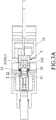
Figure 1 is a partially sectional side view illustrating a first embodiment of a return device according to the disclosure, and illustrating that the first embodiment is adapted to be mounted to a fastening tool; -
Figure 2 is a fragmentary and partially exploded perspective view of the first embodiment, illustrating a wheel support of the first embodiment; -
Figure 3 is a fragmentary and partially sectional perspective view of the first embodiment, illustrating the wheel support of the first embodiment; -
Figure 3A is a schematic fragmentary sectional view of the first embodiment, illustrating how a resilient member is connected between the wheel support and a gun body; -
Figure 4 is a fragmentary and partially sectional side view of the first embodiment, illustrating that a return wheel of the first embodiment is at a free position, and an impact member of the fastening tool is at a standby position; -
Figure 5 is a view similar toFigure 4 but illustrating that the impact member moves from the standby position to a strike position; -
Figure 6 is a view similar toFigure 4 but illustrating that the impact member is at the strike position, and the return wheel is at a return position; -
Figure 7 is a view similar toFigure 4 but illustrating that the return wheel drives the impact member to move from the strike position to the standby position; -
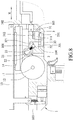
Figure 8 is a fragmentary and partially sectional side view illustrating a second embodiment of the return device according to the disclosure, illustrating that the second embodiment is adapted to be mounted to a fastening tool, and illustrating that an impact member of the fastening tool is at a strike position and a return wheel of the second embodiment is at a free position; -
Figure 9 is a view similar toFigure 8 but illustrating that the return wheel of the second embodiment is at a return position, and drives the impact member to move from a strike position to a standby position; -
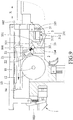
Figure 10 is a fragmentary and partially sectional side view illustrating a third embodiment of the return device according to the disclosure, illustrating that the third embodiment is adapted to be mounted to a fastening tool, and illustrating that an impact member of the fastening tool is at a strike position and a return wheel of the third embodiment is at a free position; and -
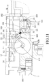
Figure 11 is a view similar toFigure 10 but illustrating that the return wheel of the third embodiment is at a return position, and drives the impact member to move from a strike position to a standby position. - Before the disclosure is described in greater detail, it should be noted that where considered appropriate, reference numerals or terminal portions of reference numerals have been repeated among the figures to indicate corresponding or analogous elements, which may optionally have similar characteristics.
- Referring to
Figures 1 to 3 , the first embodiment of a return device according to the disclosure is adapted for use in afastening tool 1. Thefastening tool 1 includes agun body 10, acentral shaft 11 mounted to thegun body 10, an electricallyrotatable flywheel 12 rotatably mounted to thegun body 10, anarm 13 pivotally mounted to thegun body 10, and animpact member 14 contactable with theflywheel 12 as a result of movement of thearm 13 toward theflywheel 12. Thegun body 10 has afirst channel 101 opening toward theflywheel 12 and theimpact member 14, afront end portion 102, and arear end portion 103 which is opposite to thefront end portion 102. - The
impact member 14 is movable in a longitudinal direction (X) of thearm 13 by virtue of a throwing force of theflywheel 12 between a standby position, where theimpact member 14 is close to therear end portion 103 of thegun body 10, and a strike position, where theimpact member 14 is close to thefront end portion 102 of thegun body 10. - The return device includes a
return wheel unit 2 and adriving unit 3. - The
return wheel unit 2 is adapted to be mounted to thegun body 10 at a location close to theflywheel 12, and includes awheel support 21 adapted to be received in thefirst channel 101 of thegun body 10, areturn wheel 22 rotatably mounted to thewheel support 21, and movable between a free position (seeFigures 4 and5 ) and a return position (seeFigures 6 and7 ), and at least oneresilient member 23 adapted to be connected between thewheel support 21 and the gun body 10 (seeFigure 3A ). When thereturn wheel 22 is at the free position, thereturn wheel 22 is not in contact with theimpact member 14. When thereturn wheel 22 is at the return position, theimpact member 14 is at the strike position and is not in contact with theflywheel 12, and thereturn wheel 22 is in contact with theflywheel 12 and theimpact member 14 such that, when theflywheel 12 rotates in a first rotational direction, thereturn wheel 22 is driven by theflywheel 12 to rotate in a second rotational direction which is opposite to the first rotational direction, and moves theimpact member 14 from the strike position to the standby position. It should be noted that, in this embodiment, thereturn wheel unit 2 includes tworesilient members 23, and the number of theresilient members 23 may be varied in other embodiments. Theresilient members 23 are respectively disposed at two opposite sides of thewheel support 21, and are disposed for providing resilient forces to bias thereturn wheel 22 to move to the free position. - The
driving unit 3 is adapted to be mounted to thegun body 10, and drives the movement of thereturn wheel 22 between the free position and the return position. Thedriving unit 3 includes adriving member 31 having amain body 311, and arod member 312 that is movable relative to themain body 311. One of themain body 311 and therod member 312 is adapted to be fixedly connected to thegun body 10. In this embodiment, themain body 311 is adapted to be fixedly connected to thegun body 10, and therod member 312 is electrically driven to push thewheel support 21 so as to move thereturn wheel 22 to the return position. - As shown in
Figure 5 , when thearm 13 pivots toward theflywheel 12 so that theimpact member 14 comes into contact with theflywheel 12, theimpact member 14 is thrown by theflywheel 12 to move from the standby position (seeFigure 4 ) to the strike position (seeFigure 6 ) to complete a nail striking operation. At the same moment, thereturn wheel 22 remains at the free position, and is not in contact with theflywheel 12. - As shown in
Figure 6 , after the nail striking operation is completed, thearm 13 pivots away from theflywheel 12, such that theimpact member 14 is not in contact with theflywheel 12. Meanwhile, therod member 312 of the drivingmember 31 is electrically driven to drive thewheel support 21 to overcome the resilient forces of theresilient members 23 so as to move toward theflywheel 12 along thefirst channel 101. When at the return position, thereturn wheel 22 is in contact with theflywheel 12 and theimpact member 14. - As shown in
Figure 7 , since theflywheel 12 continues to rotate in the first rotational direction after the nail striking operation is completed due to inertia or electric re-driving, when thereturn wheel 22 comes into contact with theflywheel 12, thereturn wheel 22 is driven by theflywheel 12 to rotate in the second rotational direction. As a result, theimpact member 14 is driven by thereturn wheel 22 to move from the strike position to the standby position to complete a returning operation. - Referring to
Figures 8 and9 , the second embodiment has a structure similar to that of the first embodiment. In this embodiment, thegun body 10 of thefastening tool 1 further has asecond channel 104 extending in a driving direction which is perpendicular to the longitudinal direction (X), and communicated with thefirst channel 101, and athird channel 105 extending parallel to thesecond channel 104. The main difference between this embodiment and the previous embodiment resides in the configuration of thedriving unit 3. - In this embodiment, the
driving unit 3 further includes a guidingmember 32 adapted to be received in thegun body 10, and a drivenmember 33. The drivingmember 31 is adapted to be received in thethird channel 105 such that, therod member 312 is movable relative to the drivenmember 33 in the driving direction. The guidingmember 32 is adapted to be received in thesecond channel 104, is movable in the driving direction, is mounted between the drivenmember 33 and thewheel support 21, and has aninclined surface 321 abutting against thewheel support 21, and disposed for pushing thewheel support 21. The drivenmember 33 is driven by thedriving member 31, and has a middle portion adapted to be pivotally connected to thegun body 10, and twoend portions 331 respectively abutting against therod member 312 of thedriving member 31 and the guidingmember 32. - With such disposition, when the
rod member 312 of the drivingmember 31 is electrically driven to move in the driving direction and pushes a corresponding one of theend portions 331 of the drivenmember 33, the drivenmember 33 pivots to push the guidingmember 32 with the other one of theend portions 331. The guidingmember 32 subsequently moves in thesecond channel 104 toward thewheel support 21 to drive thewheel support 21 with theinclined surface 321 to move in thefirst channel 101 against the resilient forces of theresilient members 23. Thereturn wheel 22 is carried by thewheel support 21 to move to the return position, and comes into contact with theflywheel 12 and theimpact member 14 so as to drive theimpact member 14 to move back to the standby position. - Referring to
Figures 10 and11 , the third embodiment has a structure similar to that of the second embodiment. The main difference between this embodiment and the previous embodiment resides in the configuration of thereturn wheel unit 2. In this embodiment, thewheel support 21 has twopivot portions 211 adapted to be pivotally and respectively connected to two opposite ends of thecentral shaft 11, and aframe portion 212 connected to thepivot portions 211, movable in thefirst channel 101, disposed for allowing thereturn wheel 22 to be rotatably mounted thereto, and driven by thedriving unit 3. - With such disposition, when the
return wheel 22 is at the free position, theflywheel 12 is in rollable contact with thereturn wheel 22 and rotates in the first rotational direction, and thereturn wheel 22 is driven by theflywheel 12 to rotate in the second rotational direction. When therod member 312 of thedriving member 31 is electrically driven to move in the driving direction and pushes a corresponding one of theend portions 331 of the drivenmember 33, the drivenmember 33 pivots to push the guidingmember 32 with the other one of theend portions 331. The guidingmember 32 subsequently moves in thesecond channel 104 toward theframe portion 212 of thewheel support 21 to drive theframe portion 212 of thewheel support 21 with theinclined surface 321 to move in thefirst channel 101 against the resilient forces of theresilient members 23. Thereturn wheel 22 is carried by thewheel support 21 to move to the return position so as to drive theimpact member 14 to move back to the standby position. - It should be noted that, since the
pivot portions 211 swing slightly when thereturn wheel 22 moves from the free position to the return position to allow smooth movement of theframe portion 212 in thefirst channel 101, thereturn wheel 22 can move along an outer periphery of theflywheel 12. As such, the slight angular movement of thepivot portions 212 is compensated for by the deformations of theresilient members 23, and the moving smoothness of theframe portion 212 of thewheel support 21 in thefirst channel 101 is not affected. - In conclusion, with the abovementioned configuration, the return device of the disclosure has the following advantages:
Thereturn wheel 22 is kept spaced apart from theimpact member 14 and does not apply a resistance to theimpact member 14 during the nail striking operation. As a result, the smoothness and the output kinetic energy of the nail striking operation are greatly increased. - In the description above, for the purposes of explanation, numerous specific details have been set forth in order to provide a thorough understanding of the embodiments. It will be apparent, however, to one skilled in the art, that one or more other embodiments may be practiced without some of these specific details. It should also be appreciated that reference throughout this specification to "one embodiment," "an embodiment," an embodiment with an indication of an ordinal number and so forth means that a particular feature, structure, or characteristic may be included in the practice of the disclosure. It should be further appreciated that in the description, various features are sometimes grouped together in a single embodiment, figure, or description thereof for the purpose of streamlining the disclosure and aiding in the understanding of various inventive aspects.
Claims (9)
- A return device adapted for use in a fastening tool (1), the fastening tool (1) including a gun body (10), an electrically rotatable flywheel (12) that is mounted rotatably to the gun body (10), and an impact member (14) that is contactable with the flywheel (12), and that is movable between a standby position, where the impact member (14) is close to a rear end portion (103) of the gun body (10), and a strike position, where the impact member (14) is close to a front end portion (102) of the gun body (10), wherein said return device comprises a return wheel unit (2) and a driving unit (3) adapted to be mounted to the gun body (10),
characterized in that:said return device further comprises a return wheel (22) that is movable between a free position, where said return wheel (22) is not in contact with the impact member (14), and a return position, where the impact member (14) is at the strike position and is not in contact with the flywheel (12), and where the return wheel (22) is in contact with the flywheel (12) and the impact member (14) such that, when the flywheel (12) rotates in a first rotational direction, the return wheel (22) is driven by the flywheel (12) to rotate in a second rotational direction which is opposite to the first rotational direction, and moves the impact member (14) from the strike position to the standby position; andthe driving unit (3) driving the movement of said return wheel (22) between the free position and the return position. - The return device as claimed in Claim 1, further characterized in that when said return wheel (22) is at the free position, the flywheel (12) is in rollable contact with said return wheel (22) and rotates in the first rotational direction, and said return wheel (22) is driven by the flywheel (12) to rotate in the second rotational direction.
- The return device as claimed in Claim 1, further characterized in that said return wheel unit (2) further includes a wheel support (21) adapted to be movably mounted to the gun body (10), said return wheel (22) being rotatably mounted to said wheel support (21).
- The return device as claimed in Claim 3, further characterized in that said return wheel unit (2) further includes at least one resilient member (23) adapted to be connected between said wheel support (21) and the gun body (10), and disposed for providing a resilient force to bias said return wheel (22) to move to the free position.
- The return device as claimed in Claim 3, the fastening tool (1) further including a central shaft (11) disposed for allowing the flywheel (12) to be rotatably mounted thereto, further characterized in that said wheel support (21) has two pivot portions (211) adapted to be pivotally and respectively connected to two opposite ends of the central shaft (11), and a frame portion (212) connected to said pivot portions (211), disposed for allowing said return wheel (22) to be rotatably mounted thereto, and movably driven by said driving unit (3).
- The return device as claimed in Claim 3, further characterized in that said driving unit (3) includes a driving member (31) having a main body (311), and a rod member (312) that is movable relative to said main body (311), one of said main body (311) and said rod member (312) being adapted to be fixedly connected to the gun body (10).
- The return device as claimed in Claim 6, further characterized in that said rod member (312) of said driving unit (3) is electrically driven to push said wheel support (21) so as to move said return wheel (22) to the return position.
- The return device as claimed in Claim 6, further characterized in that said driving unit (31) further includes a driven member (33) adapted to be pivotally connected to the gun body (10), and driven by said driving member (31) to move said wheel support (21).
- The return device as claimed in Claim 8, further characterized in that:said driving unit (3) further includes a guiding member (32) adapted to be received in the gun body (10), mounted between said driven member (33) and said wheel support (21), and movable in a driving direction which is perpendicular to the longitudinal direction (X);said driven member (33) has a middle portion adapted to be pivotally connected to the gun body (10), and two end portions (331) respectively abutting against said rod member (312) of said driving member (31) and said guiding member (32); andsaid guiding member (32) has an inclined surface (321) abutting against said wheel support (21) such that, when said rod member (312) of said driving member (31) moves in the driving direction to push a corresponding one of said end portions (331) of said driven member (33), said driven member (33) pivots so that the other one of said end portions (331) pushes said guiding member (32) to move said wheel support (21).
Applications Claiming Priority (1)
| Application Number | Priority Date | Filing Date | Title |
|---|---|---|---|
| TW106101657A TWI714707B (en) | 2017-01-18 | 2017-01-18 | Unobstructed recovery device of electric nail gun |
Publications (2)
| Publication Number | Publication Date |
|---|---|
| EP3378600A1 EP3378600A1 (en) | 2018-09-26 |
| EP3378600B1 true EP3378600B1 (en) | 2019-12-25 |
Family
ID=61002897
Family Applications (1)
| Application Number | Title | Priority Date | Filing Date |
|---|---|---|---|
| EP18152076.8A Active EP3378600B1 (en) | 2017-01-18 | 2018-01-17 | Return device |
Country Status (4)
| Country | Link |
|---|---|
| US (1) | US10549413B2 (en) |
| EP (1) | EP3378600B1 (en) |
| JP (1) | JP6584540B2 (en) |
| TW (1) | TWI714707B (en) |
Families Citing this family (2)
| Publication number | Priority date | Publication date | Assignee | Title |
|---|---|---|---|---|
| TWI772797B (en) * | 2020-05-18 | 2022-08-01 | 鑽全實業股份有限公司 | Impact device for releasable rails |
| TWI809915B (en) * | 2022-06-13 | 2023-07-21 | 力肯實業股份有限公司 | Flywheel driving nailing device of electric nail gun |
Family Cites Families (19)
| Publication number | Priority date | Publication date | Assignee | Title |
|---|---|---|---|---|
| US4215808A (en) * | 1978-12-22 | 1980-08-05 | Sollberger Roger W | Portable electric fastener driving apparatus |
| US4964558A (en) * | 1989-05-26 | 1990-10-23 | Sencorp | Electro-mechanical fastener driving tool |
| US6607111B2 (en) * | 2000-12-22 | 2003-08-19 | Senco Products, Inc. | Flywheel operated tool |
| US6997367B2 (en) * | 2002-07-25 | 2006-02-14 | Yih Kai Enterprise Co., Ltd. | Hand-held nailing tool |
| US6971567B1 (en) * | 2004-10-29 | 2005-12-06 | Black & Decker Inc. | Electronic control of a cordless fastening tool |
| US20060180631A1 (en) * | 2005-02-16 | 2006-08-17 | Chris Pedicini | Electric motor driven energy storage device for impacting |
| DE102005000061A1 (en) * | 2005-05-18 | 2006-11-23 | Hilti Ag | Electrically operated tacker |
| JP2007237351A (en) * | 2006-03-09 | 2007-09-20 | Hitachi Koki Co Ltd | Portable hammering machine |
| AU2008308801B2 (en) * | 2007-10-05 | 2012-03-22 | Kyocera Senco Industrial Tools, Inc. | Fastener driving tool using gas spring |
| US8763874B2 (en) * | 2007-10-05 | 2014-07-01 | Senco Brands, Inc. | Gas spring fastener driving tool with improved lifter and latch mechanisms |
| EP2514568B1 (en) * | 2008-05-30 | 2013-10-02 | Black & Decker Inc. | Fastener driving tool |
| TWI385058B (en) * | 2010-04-26 | 2013-02-11 | Basso Ind Corp | Electric nail gun drive device |
| TW201438850A (en) | 2013-04-11 | 2014-10-16 | Basso Ind Corp | Recycling apparatus for electrically-propelled nail gun |
| TWM482482U (en) | 2014-03-10 | 2014-07-21 | Basso Ind Corp | Recovery device of electric nail gun |
| TWI607839B (en) * | 2014-06-05 | 2017-12-11 | Basso Ind Corp | Portable power tool and impact block resetting device |
| US9539714B1 (en) * | 2014-10-07 | 2017-01-10 | Tricord Solutions, Inc. | Fastener driving apparatus |
| EP3253534B1 (en) * | 2015-02-06 | 2020-05-06 | Milwaukee Electric Tool Corporation | Gas spring-powered fastener driver |
| TWM513764U (en) * | 2015-06-11 | 2015-12-11 | Basso Ind Corp | Recovering device for electric nail gun |
| TWM513761U (en) | 2015-07-16 | 2015-12-11 | yong-tang Zhang | Improved faucet assembling/disassembling tool |
-
2017
- 2017-01-18 TW TW106101657A patent/TWI714707B/en active
-
2018
- 2018-01-16 US US15/872,159 patent/US10549413B2/en active Active
- 2018-01-17 JP JP2018005505A patent/JP6584540B2/en active Active
- 2018-01-17 EP EP18152076.8A patent/EP3378600B1/en active Active
Non-Patent Citations (1)
| Title |
|---|
| None * |
Also Published As
| Publication number | Publication date |
|---|---|
| EP3378600A1 (en) | 2018-09-26 |
| TWI714707B (en) | 2021-01-01 |
| TW201827176A (en) | 2018-08-01 |
| JP2018118374A (en) | 2018-08-02 |
| US10549413B2 (en) | 2020-02-04 |
| JP6584540B2 (en) | 2019-10-02 |
| US20190022843A1 (en) | 2019-01-24 |
Similar Documents
| Publication | Publication Date | Title |
|---|---|---|
| US11305409B2 (en) | Retrieving device and impact mechanism for an electric nail gun having the same | |
| US7513407B1 (en) | Counterforce-counteracting device for a nailer | |
| EP2644323B1 (en) | Electric nail gun | |
| US8479966B2 (en) | Floating impact apparatus for electrical nail gun | |
| AU751720B2 (en) | Multi-stroke fastening device | |
| EP3156182B1 (en) | Driving device | |
| EP3378600B1 (en) | Return device | |
| US20150251300A1 (en) | Electric nail gun | |
| JPS6048314B2 (en) | impact tools | |
| US11518013B2 (en) | Electric nail gun | |
| EP2433752A2 (en) | Driving unit for an electric nail gun. | |
| US20210354278A1 (en) | Impact device | |
| US9803948B2 (en) | Trigger emulation mechanism of electric gun | |
| US20150306753A1 (en) | Adjusting device for an electric nail gun | |
| US20220161405A1 (en) | Retaining device for use with a nail gun | |
| US11738431B2 (en) | Retaining device for use with a nail gun | |
| GB2391178A (en) | Ball trapping and shooting device | |
| EP4029653B1 (en) | Retaining device for use with a nail gun | |
| US20230415318A1 (en) | Electric nail gun | |
| GB2452935A (en) | Counterforce device for a nailer | |
| JPS6150577A (en) | Hitting exerciser |
Legal Events
| Date | Code | Title | Description |
|---|---|---|---|
| PUAI | Public reference made under article 153(3) epc to a published international application that has entered the european phase |
Free format text: ORIGINAL CODE: 0009012 |
|
| STAA | Information on the status of an ep patent application or granted ep patent |
Free format text: STATUS: REQUEST FOR EXAMINATION WAS MADE |
|
| 17P | Request for examination filed |
Effective date: 20180117 |
|
| AK | Designated contracting states |
Kind code of ref document: A1 Designated state(s): AL AT BE BG CH CY CZ DE DK EE ES FI FR GB GR HR HU IE IS IT LI LT LU LV MC MK MT NL NO PL PT RO RS SE SI SK SM TR |
|
| AX | Request for extension of the european patent |
Extension state: BA ME |
|
| GRAP | Despatch of communication of intention to grant a patent |
Free format text: ORIGINAL CODE: EPIDOSNIGR1 |
|
| STAA | Information on the status of an ep patent application or granted ep patent |
Free format text: STATUS: GRANT OF PATENT IS INTENDED |
|
| INTG | Intention to grant announced |
Effective date: 20190611 |
|
| GRAJ | Information related to disapproval of communication of intention to grant by the applicant or resumption of examination proceedings by the epo deleted |
Free format text: ORIGINAL CODE: EPIDOSDIGR1 |
|
| GRAL | Information related to payment of fee for publishing/printing deleted |
Free format text: ORIGINAL CODE: EPIDOSDIGR3 |
|
| STAA | Information on the status of an ep patent application or granted ep patent |
Free format text: STATUS: REQUEST FOR EXAMINATION WAS MADE |
|
| GRAS | Grant fee paid |
Free format text: ORIGINAL CODE: EPIDOSNIGR3 |
|
| GRAR | Information related to intention to grant a patent recorded |
Free format text: ORIGINAL CODE: EPIDOSNIGR71 |
|
| STAA | Information on the status of an ep patent application or granted ep patent |
Free format text: STATUS: GRANT OF PATENT IS INTENDED |
|
| INTC | Intention to grant announced (deleted) | ||
| GRAA | (expected) grant |
Free format text: ORIGINAL CODE: 0009210 |
|
| STAA | Information on the status of an ep patent application or granted ep patent |
Free format text: STATUS: THE PATENT HAS BEEN GRANTED |
|
| AK | Designated contracting states |
Kind code of ref document: B1 Designated state(s): AL AT BE BG CH CY CZ DE DK EE ES FI FR GB GR HR HU IE IS IT LI LT LU LV MC MK MT NL NO PL PT RO RS SE SI SK SM TR |
|
| INTG | Intention to grant announced |
Effective date: 20191119 |
|
| REG | Reference to a national code |
Ref country code: GB Ref legal event code: FG4D |
|
| REG | Reference to a national code |
Ref country code: CH Ref legal event code: EP |
|
| REG | Reference to a national code |
Ref country code: DE Ref legal event code: R096 Ref document number: 602018001696 Country of ref document: DE |
|
| REG | Reference to a national code |
Ref country code: AT Ref legal event code: REF Ref document number: 1216647 Country of ref document: AT Kind code of ref document: T Effective date: 20200115 |
|
| REG | Reference to a national code |
Ref country code: IE Ref legal event code: FG4D |
|
| REG | Reference to a national code |
Ref country code: NL Ref legal event code: MP Effective date: 20191225 |
|
| PG25 | Lapsed in a contracting state [announced via postgrant information from national office to epo] |
Ref country code: LT Free format text: LAPSE BECAUSE OF FAILURE TO SUBMIT A TRANSLATION OF THE DESCRIPTION OR TO PAY THE FEE WITHIN THE PRESCRIBED TIME-LIMIT Effective date: 20191225 Ref country code: NO Free format text: LAPSE BECAUSE OF FAILURE TO SUBMIT A TRANSLATION OF THE DESCRIPTION OR TO PAY THE FEE WITHIN THE PRESCRIBED TIME-LIMIT Effective date: 20200325 Ref country code: GR Free format text: LAPSE BECAUSE OF FAILURE TO SUBMIT A TRANSLATION OF THE DESCRIPTION OR TO PAY THE FEE WITHIN THE PRESCRIBED TIME-LIMIT Effective date: 20200326 Ref country code: FI Free format text: LAPSE BECAUSE OF FAILURE TO SUBMIT A TRANSLATION OF THE DESCRIPTION OR TO PAY THE FEE WITHIN THE PRESCRIBED TIME-LIMIT Effective date: 20191225 Ref country code: BG Free format text: LAPSE BECAUSE OF FAILURE TO SUBMIT A TRANSLATION OF THE DESCRIPTION OR TO PAY THE FEE WITHIN THE PRESCRIBED TIME-LIMIT Effective date: 20200325 Ref country code: SE Free format text: LAPSE BECAUSE OF FAILURE TO SUBMIT A TRANSLATION OF THE DESCRIPTION OR TO PAY THE FEE WITHIN THE PRESCRIBED TIME-LIMIT Effective date: 20191225 Ref country code: LV Free format text: LAPSE BECAUSE OF FAILURE TO SUBMIT A TRANSLATION OF THE DESCRIPTION OR TO PAY THE FEE WITHIN THE PRESCRIBED TIME-LIMIT Effective date: 20191225 |
|
| REG | Reference to a national code |
Ref country code: LT Ref legal event code: MG4D |
|
| PG25 | Lapsed in a contracting state [announced via postgrant information from national office to epo] |
Ref country code: RS Free format text: LAPSE BECAUSE OF FAILURE TO SUBMIT A TRANSLATION OF THE DESCRIPTION OR TO PAY THE FEE WITHIN THE PRESCRIBED TIME-LIMIT Effective date: 20191225 Ref country code: HR Free format text: LAPSE BECAUSE OF FAILURE TO SUBMIT A TRANSLATION OF THE DESCRIPTION OR TO PAY THE FEE WITHIN THE PRESCRIBED TIME-LIMIT Effective date: 20191225 |
|
| PG25 | Lapsed in a contracting state [announced via postgrant information from national office to epo] |
Ref country code: AL Free format text: LAPSE BECAUSE OF FAILURE TO SUBMIT A TRANSLATION OF THE DESCRIPTION OR TO PAY THE FEE WITHIN THE PRESCRIBED TIME-LIMIT Effective date: 20191225 |
|
| PG25 | Lapsed in a contracting state [announced via postgrant information from national office to epo] |
Ref country code: EE Free format text: LAPSE BECAUSE OF FAILURE TO SUBMIT A TRANSLATION OF THE DESCRIPTION OR TO PAY THE FEE WITHIN THE PRESCRIBED TIME-LIMIT Effective date: 20191225 Ref country code: PT Free format text: LAPSE BECAUSE OF FAILURE TO SUBMIT A TRANSLATION OF THE DESCRIPTION OR TO PAY THE FEE WITHIN THE PRESCRIBED TIME-LIMIT Effective date: 20200520 Ref country code: CZ Free format text: LAPSE BECAUSE OF FAILURE TO SUBMIT A TRANSLATION OF THE DESCRIPTION OR TO PAY THE FEE WITHIN THE PRESCRIBED TIME-LIMIT Effective date: 20191225 Ref country code: RO Free format text: LAPSE BECAUSE OF FAILURE TO SUBMIT A TRANSLATION OF THE DESCRIPTION OR TO PAY THE FEE WITHIN THE PRESCRIBED TIME-LIMIT Effective date: 20191225 Ref country code: NL Free format text: LAPSE BECAUSE OF FAILURE TO SUBMIT A TRANSLATION OF THE DESCRIPTION OR TO PAY THE FEE WITHIN THE PRESCRIBED TIME-LIMIT Effective date: 20191225 |
|
| PG25 | Lapsed in a contracting state [announced via postgrant information from national office to epo] |
Ref country code: IS Free format text: LAPSE BECAUSE OF FAILURE TO SUBMIT A TRANSLATION OF THE DESCRIPTION OR TO PAY THE FEE WITHIN THE PRESCRIBED TIME-LIMIT Effective date: 20200425 Ref country code: SK Free format text: LAPSE BECAUSE OF FAILURE TO SUBMIT A TRANSLATION OF THE DESCRIPTION OR TO PAY THE FEE WITHIN THE PRESCRIBED TIME-LIMIT Effective date: 20191225 Ref country code: SM Free format text: LAPSE BECAUSE OF FAILURE TO SUBMIT A TRANSLATION OF THE DESCRIPTION OR TO PAY THE FEE WITHIN THE PRESCRIBED TIME-LIMIT Effective date: 20191225 |
|
| REG | Reference to a national code |
Ref country code: DE Ref legal event code: R097 Ref document number: 602018001696 Country of ref document: DE |
|
| PG25 | Lapsed in a contracting state [announced via postgrant information from national office to epo] |
Ref country code: MC Free format text: LAPSE BECAUSE OF FAILURE TO SUBMIT A TRANSLATION OF THE DESCRIPTION OR TO PAY THE FEE WITHIN THE PRESCRIBED TIME-LIMIT Effective date: 20191225 |
|
| REG | Reference to a national code |
Ref country code: BE Ref legal event code: MM Effective date: 20200131 |
|
| PG25 | Lapsed in a contracting state [announced via postgrant information from national office to epo] |
Ref country code: ES Free format text: LAPSE BECAUSE OF FAILURE TO SUBMIT A TRANSLATION OF THE DESCRIPTION OR TO PAY THE FEE WITHIN THE PRESCRIBED TIME-LIMIT Effective date: 20191225 Ref country code: LU Free format text: LAPSE BECAUSE OF NON-PAYMENT OF DUE FEES Effective date: 20200117 Ref country code: DK Free format text: LAPSE BECAUSE OF FAILURE TO SUBMIT A TRANSLATION OF THE DESCRIPTION OR TO PAY THE FEE WITHIN THE PRESCRIBED TIME-LIMIT Effective date: 20191225 |
|
| PLBE | No opposition filed within time limit |
Free format text: ORIGINAL CODE: 0009261 |
|
| STAA | Information on the status of an ep patent application or granted ep patent |
Free format text: STATUS: NO OPPOSITION FILED WITHIN TIME LIMIT |
|
| REG | Reference to a national code |
Ref country code: AT Ref legal event code: MK05 Ref document number: 1216647 Country of ref document: AT Kind code of ref document: T Effective date: 20191225 |
|
| PG25 | Lapsed in a contracting state [announced via postgrant information from national office to epo] |
Ref country code: SI Free format text: LAPSE BECAUSE OF FAILURE TO SUBMIT A TRANSLATION OF THE DESCRIPTION OR TO PAY THE FEE WITHIN THE PRESCRIBED TIME-LIMIT Effective date: 20191225 Ref country code: BE Free format text: LAPSE BECAUSE OF NON-PAYMENT OF DUE FEES Effective date: 20200131 |
|
| 26N | No opposition filed |
Effective date: 20200928 |
|
| PG25 | Lapsed in a contracting state [announced via postgrant information from national office to epo] |
Ref country code: IE Free format text: LAPSE BECAUSE OF NON-PAYMENT OF DUE FEES Effective date: 20200117 Ref country code: IT Free format text: LAPSE BECAUSE OF FAILURE TO SUBMIT A TRANSLATION OF THE DESCRIPTION OR TO PAY THE FEE WITHIN THE PRESCRIBED TIME-LIMIT Effective date: 20191225 Ref country code: AT Free format text: LAPSE BECAUSE OF FAILURE TO SUBMIT A TRANSLATION OF THE DESCRIPTION OR TO PAY THE FEE WITHIN THE PRESCRIBED TIME-LIMIT Effective date: 20191225 |
|
| PG25 | Lapsed in a contracting state [announced via postgrant information from national office to epo] |
Ref country code: PL Free format text: LAPSE BECAUSE OF FAILURE TO SUBMIT A TRANSLATION OF THE DESCRIPTION OR TO PAY THE FEE WITHIN THE PRESCRIBED TIME-LIMIT Effective date: 20191225 |
|
| REG | Reference to a national code |
Ref country code: CH Ref legal event code: PL |
|
| PG25 | Lapsed in a contracting state [announced via postgrant information from national office to epo] |
Ref country code: LI Free format text: LAPSE BECAUSE OF NON-PAYMENT OF DUE FEES Effective date: 20210131 Ref country code: CH Free format text: LAPSE BECAUSE OF NON-PAYMENT OF DUE FEES Effective date: 20210131 |
|
| PG25 | Lapsed in a contracting state [announced via postgrant information from national office to epo] |
Ref country code: TR Free format text: LAPSE BECAUSE OF FAILURE TO SUBMIT A TRANSLATION OF THE DESCRIPTION OR TO PAY THE FEE WITHIN THE PRESCRIBED TIME-LIMIT Effective date: 20191225 Ref country code: MT Free format text: LAPSE BECAUSE OF FAILURE TO SUBMIT A TRANSLATION OF THE DESCRIPTION OR TO PAY THE FEE WITHIN THE PRESCRIBED TIME-LIMIT Effective date: 20191225 Ref country code: CY Free format text: LAPSE BECAUSE OF FAILURE TO SUBMIT A TRANSLATION OF THE DESCRIPTION OR TO PAY THE FEE WITHIN THE PRESCRIBED TIME-LIMIT Effective date: 20191225 |
|
| PG25 | Lapsed in a contracting state [announced via postgrant information from national office to epo] |
Ref country code: MK Free format text: LAPSE BECAUSE OF FAILURE TO SUBMIT A TRANSLATION OF THE DESCRIPTION OR TO PAY THE FEE WITHIN THE PRESCRIBED TIME-LIMIT Effective date: 20191225 |
|
| PGFP | Annual fee paid to national office [announced via postgrant information from national office to epo] |
Ref country code: DE Payment date: 20221130 Year of fee payment: 6 |
|
| PGFP | Annual fee paid to national office [announced via postgrant information from national office to epo] |
Ref country code: GB Payment date: 20231130 Year of fee payment: 7 |
|
| PGFP | Annual fee paid to national office [announced via postgrant information from national office to epo] |
Ref country code: FR Payment date: 20231212 Year of fee payment: 7 |