EP3378538A1 - A pressure regulating unit for regulating pressure resulted from a fire in a room - Google Patents
A pressure regulating unit for regulating pressure resulted from a fire in a room Download PDFInfo
- Publication number
- EP3378538A1 EP3378538A1 EP17162064.4A EP17162064A EP3378538A1 EP 3378538 A1 EP3378538 A1 EP 3378538A1 EP 17162064 A EP17162064 A EP 17162064A EP 3378538 A1 EP3378538 A1 EP 3378538A1
- Authority
- EP
- European Patent Office
- Prior art keywords
- pressure
- room
- threshold level
- regulating unit
- valve member
- Prior art date
- Legal status (The legal status is an assumption and is not a legal conclusion. Google has not performed a legal analysis and makes no representation as to the accuracy of the status listed.)
- Withdrawn
Links
Images


Classifications
-
- F—MECHANICAL ENGINEERING; LIGHTING; HEATING; WEAPONS; BLASTING
- F16—ENGINEERING ELEMENTS AND UNITS; GENERAL MEASURES FOR PRODUCING AND MAINTAINING EFFECTIVE FUNCTIONING OF MACHINES OR INSTALLATIONS; THERMAL INSULATION IN GENERAL
- F16K—VALVES; TAPS; COCKS; ACTUATING-FLOATS; DEVICES FOR VENTING OR AERATING
- F16K17/00—Safety valves; Equalising valves, e.g. pressure relief valves
- F16K17/18—Safety valves; Equalising valves, e.g. pressure relief valves opening on surplus pressure on either side
- F16K17/19—Equalising valves predominantly for tanks
- F16K17/196—Equalising valves predominantly for tanks spring-loaded
-
- A—HUMAN NECESSITIES
- A62—LIFE-SAVING; FIRE-FIGHTING
- A62B—DEVICES, APPARATUS OR METHODS FOR LIFE-SAVING
- A62B3/00—Devices or single parts for facilitating escape from buildings or the like, e.g. protection shields, protection screens; Portable devices for preventing smoke penetrating into distinct parts of buildings
-
- A—HUMAN NECESSITIES
- A62—LIFE-SAVING; FIRE-FIGHTING
- A62B—DEVICES, APPARATUS OR METHODS FOR LIFE-SAVING
- A62B5/00—Other devices for rescuing from fire
-
- A—HUMAN NECESSITIES
- A62—LIFE-SAVING; FIRE-FIGHTING
- A62C—FIRE-FIGHTING
- A62C2/00—Fire prevention or containment
- A62C2/06—Physical fire-barriers
- A62C2/12—Hinged dampers
-
- F—MECHANICAL ENGINEERING; LIGHTING; HEATING; WEAPONS; BLASTING
- F24—HEATING; RANGES; VENTILATING
- F24F—AIR-CONDITIONING; AIR-HUMIDIFICATION; VENTILATION; USE OF AIR CURRENTS FOR SCREENING
- F24F11/00—Control or safety arrangements
- F24F11/30—Control or safety arrangements for purposes related to the operation of the system, e.g. for safety or monitoring
- F24F11/32—Responding to malfunctions or emergencies
- F24F11/33—Responding to malfunctions or emergencies to fire, excessive heat or smoke
Definitions
- the present invention relates to fire valve units for preventing effects of a fire in a building.
- the inventor has realized that there are a number of problems arising from the pressure fluctuation in a building during a fire. Therefore, there is a need of improving how the buildings handling the pressure during a fire. Specifically, the inventor has realized that the force required for manually opening of doors is directly affected by the pressure in the room, and that the pressure on a door dramatically exceed the construction requirements on forces required to open doors upon a fire. This has even caused deaths during fires, where the victims have been found dead on the inside of the door, since they have not had enough strength to open the door due to the pressure generated by the fire.
- An object of the present invention is to provide a solution that at least alleviated the above mentioned problems related to pressure differences during a fire in a closed room.
- the invention is based on the inventor's insight that by providing a room with an opening to an outside of the room and by installing a 2-way valve device in said opening, the pressure increase and decrease during a fire may be alleviated. Further, by keeping the 2-way valve device closed under normal pressure levels, the strict construction regulations related to energy efficiency may also be met.
- a pressure regulating unit for regulating the pressure resulted from a fire in a room volume, comprising a main body having a first opening adapted to be mounted in fluid connection to the inside of said room volume, and a second opening adapted to be mounted in fluid connection to an outside of said room volume.
- the pressure regulating device further comprise a valve member arranged between said first opening and said second opening, said valve member being movable between a first closed position and a second open position. Further, the valve member opens when the pressure in said room volume exceeds a predetermined positive pressure threshold level or falls below a predetermined negative pressure threshold level and is in said closed position during pressure levels in the room volume being between said positive pressure threshold level and negative pressure threshold level.
- a pressure regulating unit may be provided that enables someone who is trapped inside a room with a fire to be able to open the door to exit the room comprising the fire. This invention may therefore save lives.
- any "in fluid connection” should be understood as a gaseous fluid may flow between the first and second object being in fluid connection.
- the valve member automatically returns to the closed position when the pressure in said room volume returns to a level that lies between a predetermined positive pressure threshold level and a predetermined negative pressure threshold level.
- the valve member does not have to be repositioned into the closed position manually after an increase in pressure in the room volume.
- the positive pressure threshold level and/or said negative pressure threshold level is calculated based on the force required to evacuate the room, by e.g. opening the door or a window in a room.
- the door/window may always be openable to user.
- the positive pressure threshold level and/or said negative pressure threshold level is at least about 50Pa/-50Pa, least about 100Pa/-100Pa, at least about 150Pa/-150Pa, or at least about 250Pa/-250Pa.
- the valve unit is sized and formed so that the pressure increase/decrease in the room volume alone moves the valve member from the closed position to the open position.
- no electronic equipment such as sensors and/or motors need to be used. It is of course possible to use electronic sensors and motors, but the solution will be much more expensive than a mechanical solution.
- valve means is deformable so that it may change from an open state to a closed state and vice versa.
- valve means is deformable by means of a flexible material.
- a fire proof deformable textile may be used for the valve member.
- the pressure regulating unit further comprise a returning means for returning the valve means from the open position to the closed position.
- the force that the returning means exerts on the valve means for bringing it to, or keeping it in, the closed positon is based on calculations derived from the positive pressure threshold level or negative pressure threshold.
- the force exerted from the returning means on the valve means for bringing it to, or keeping it in, the closed positon corresponds to a force the pressure at either the positive pressure threshold level or negative pressure threshold level exerts on the valve means.
- the returning means is a springing means, such as a spring, coil spring or similar.
- the valve member comprises an outlet portion for letting out air during pressure levels above said positive pressure threshold level and one inlet portion for letting in air during pressure levels below the negative pressure threshold level.
- the outlet portion is axially displaced relative the inlet portion, so as to create an intermediate insulating volume.
- outlet portion is juxtaposed arranged relative the inlet portion.
- the above-mention problems are at least partly alleviated by providing a room comprising a plurality of surfaces defining a room volume and restricting flow of gas to/from said room volume, an opening in at least one of said plurality of surfaces, and a pressure regulating unit according to any of above mentioned embodiments. Further, the pressure regulating unit is installed in the opening to allow flow of gas to/from the room to pressure neutralize the room. Hereby, exiting the room during a fire is facilitated.
- the room comprise additional openings in at least one of said plurality of surfaces, and one pressure regulating unit according to any of the above mentioned embodiments installed in each one of said additional openings to allow flow of gas to/from said room to pressure neutralize said room.
- one pressure regulating unit according to any of the above mentioned embodiments installed in each one of said additional openings to allow flow of gas to/from said room to pressure neutralize said room.
- valve member is arranged onto a rotational axle and adapted to rotate between the first closed position and the second open position.
- valve member's outlet portion for letting out air during pressure levels above said positive pressure threshold level is arranged on a first side of the rotational axle, and the inlet portion for letting in air during pressure levels below the negative pressure threshold level arranged a second side of the rotational axle, being opposite of the first side.
- valve member 13 is adapted to rotate around the rotational axle as a consequence of that the outlet portion is opened, or that the inlet portion is opened.
- the outlet portion for letting out air during pressure levels above said positive pressure threshold level pivots around the rotational axle without affecting the orientation of the inlet portion which may be individually pivotable for letting in air during pressure levels below the negative pressure threshold level.
- outlet portion and the inlet portion are coupled so as to move together around the rotational axle, but in opposite rotational directions.
- At least a portion of the valve member comprise an arched surface.
- the valve member may be designed to rotate around the central axle as a result of the pressure difference.
- the pressure regulating unit comprise a stopping means for stopping the inlet portion, the outlet portion, and/or the valve member in its stopping position. In some embodiments there may be several stopping means arranged for one or several components.
- At least two portions of the valve member comprise an arched surface, wherein the arched surfaces are arranged on different sides of the rotational axle, and one of the facing the first opening and the other one facing the second opening.
- the valve member may be designed to rotate around the central axle as a result of the pressure difference being both negative or positive.
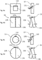
- Fig. 1 illustrate a pressure regulating unit 1 according to one embodiment of the invention, wherein the pressure regulating unit 1 comprise a main body 10.
- the main body is circular.
- the main body shape may however be of any shape, as long as the shape fits into a hole in one of the walls/roof/ceiling in the room.
- An advantage with a circular, tube formed main body 10 is that the hole may be easily achieved by a hole saw with a diameter corresponding to the outer diameter of the main body.
- the outer diameter may be chosen so that enough air may flow though the pressure regulating unit 1, to pressure relief the room volume during a fire.
- the outer diameter may be about 50-500mm, or preferably about 100-250mm or most preferably about 130-200mm.
- the main body 10 comprise a first opening 11 and a second opening 12.
- the first opening 11 is to be installed towards the inside of the room volume, and the second opening 12 towards an outside of the room.
- the main body fluidly connects the room volume with a volume outside of the room.
- the outside of the room is directly or indirectly connected to the outside of a building, so that an efficient pressure relief may be achieved.
- fig 1 illustrates that the pressure regulating unit comprise a valve member 13.
- the valve member 13 is adapted to move from a first closed position A to a second open position B (not shown in fig 1 ). This is further explained when figures 4-5 are described below.
- the valve member 13 is in the closed position A, the room volume may be substantially closed, so at to meet the energy efficiency regulations.
- fig. 2 shows a top view of an illustration of a room 100 defining a room volume.
- Afire 101 is burning inside the room and a pressure regulating unit 1 is installed in one of the walls 102.
- a door 103 is illustrated in the room.
- the pressure regulating unit may of course be arranged in any wall and/or ceiling or even floor of the room. If the room is large, it may be advantageous to have a plurality of pressure regulating units in the room volume. Also, if there are dividing walls inside a room, having a pressure regulating unit 1 installed in each portion of the room may be beneficial, especially if there are doors that would be opened to exit the room, in case of a fire.
- fig. 3 shows a graph P(t) illustrating the pressure difference over time during a fire in a closed room.
- the initial pressure is starting at a point wherein the pressure on the inside of the room is about the same as the pressure on the outside of the room. This starting pressure may be e.g. 1 bar (about 100 000 Pa).
- the graph is generated from data during measurements in fires in closed rooms conducted by the applicant. In the experiments a fluid heptane was lit in a room volume while measuring the pressure in the room during the fire development in the room. As can be seen from this graph, when a fire takes place in the room, within less than one minute the relative pressure increase to a level above the denoted positive pressure threshold level P P .
- This pressure level is denoted as a dashed upper line and as about +100Pa in the illustration. If the door has a surface of 2m 2 the force acting on the door is 200N at +100Pa increase in pressure relative the outside. Since the door is usually hinged at one side and has a handle at the opposite side, the force for opening the door is about half the force of the force acting on the door. That is, for +100 Pa the force for opening the door is about 100N.
- a negative pressure threshold level P N is denoted as the dashed lower line and as about -100Pa in the graph.
- Two striped areas P H , P L indicating when the pressure is either higher P H than the positive pressure threshold level P P , or lower P L than the predetermined negative pressure threshold level P N is denoted in the graph.
- the high pressure range P H is reached already within the minute of the fire in the measurements. Before the high pressure range P H is reached, it is possible to open the door, illustrated by an opening pressure Po corresponding to the pressure in the room when the door is openable with manpower (or according to construction regulations). The time during which the pressure in the room corresponds to an opening pressure Po is denoted in the graph.
- the positive pressure threshold level P P and the negative pressure threshold level P N may be chosen so that the valve opens corresponding to a desired force level for opening the door.
- the pressure regulating unit By introducing the pressure regulating unit into the room, the variation of pressure as a function over time may be reduced.
- the maximum increase may be kept in pressure levels around the positive pressure threshold level P P .
- the maximum negative pressure drop may be kept within the negative pressure threshold level P N .
- the door may be openable throughout the fire in the room.
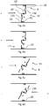
- fig. 4a-4d shows the valve member according to four different embodiments, wherein each figure shows a front view and a side view of the embodiment.
- Fig 4a show a valve member 13 having a movable restriction device 131.
- the restriction device 131 is closed during normal pressure Po levels, corresponding to the pressure outside of the room. Further the restriction device 131 opens upon a pressure difference either exceeding the positive pressure threshold level P P or falling below the negative pressure threshold level P N .
- the restriction device 131 is pivotably arranged in its top portion, and arranged within the valve member 13. The restriction device may pivot in a first direction to allow flow out of the room volume and in a second direction to allow flow into the room volume.
- the restriction device may be resiliently arranged so as to return to its closed position during a pressure Po being in between the positive pressure threshold level P P and the negative pressure threshold level P N . Further, the restriction device may return to its closed position by merely gravitation if the pivotal arrangement is arranged in its top portion. Hereby, the weight of the restriction device will pull it into the closed position, when being pushed by the increased/decreased pressure inside the room. Further, the right part of the figure show how air can pass through the valve member 13 in an open state. The arrows in respective direction indicates the movement of the restriction member 131 to allow inlet flow and outlet flow, respectively.
- fig 4b disclose the valve member 13 being divided into an outlet portion 135 for letting out air during pressure levels above said positive pressure P P threshold level and one inlet portion 136 for letting in air in the room volume during pressure levels below the negative pressure P N threshold level.
- the inlet portion 136 comprise a returning means 15, in this case being in the form of a coil spring.
- the returning means 15 is also shown in the side view to the right, and there it is shown that the outlet portion 135 also comprise a returning means 15 in the form of a coil spring.
- the returning means 15 may be any type of means for bringing the inlet portion into the closed position. E.g. an electric actuator or a resilient material or device.
- the returning means may be provided on the opening side of the inlet/outlet portion so as to push the portion back into the closed position, it can also be provided on the opposite side so as to pull the portion back into the closed position.
- the inlet portion 136 and or outlet portion 135 may return to its closed position by merely gravitation if the pivotal arrangement is arranged in its top portion.
- the pressure regulating unit 1 may comprise a stopping means 65 for stopping the inlet portion 136 and/or the outlet portion 137 in its closed position, so that the returning means 15 hold the inlet portion or outlet portion against said stopping means.
- Said stopping means may be a projection from the main body 10.
- the right part of fig 4b show how air can pass through the valve member 13 in an open state. The arrows in respective direction indicates the movement of the valve member (inlet and outlet portions) to allow inlet flow and outlet flow, respectively.
- Fig 4c illustrates a valve member 13, having a similar set-up as in fig 4a , but with a round outer form instead of a rectangular outer form. Also, the restricting device 131 is round in the embodiment disclosed in fig 4c .
- Fig 4d illustrates a valve member 13, having a similar set-up as in fig 4b , but with a round outer form instead of a rectangular outer form.
- valve member 13 shows the valve member according to four different embodiments, wherein each figure shows a front view and a side view of the embodiment.
- the valve means 13 is a flexible material 137 being deformable.
- the flexible material may be a fire proof deformable textile.
- the illustrated flexible material 137 is designed to open in response to a pressure difference in the room volume relative the pressure outside of the room volume.
- the left illustrations in both fig. 5a and 5b illustrates cross-sectional end views of the valve means 13.
- the flexible material 137 may either be in a closed state A or an open state B. During the open states B the flexible material 137 may either be in an inlet position or an outlet position, depending on if there is a positive or negative pressure in the room volume that is to be pressure relieved.
- the flexible material 137 is attached, either directly or indirectly, to the main body 10 of the pressure regulating unit 1.
- the flexible material 137 may be attached to the main body 10 by means of a holding member 138, e.g. being a plastic tube holding the flexible material 137 to the main body 10.
- an elastic member 139 is illustrated.
- the elastic member is arranged to close the flexible material 137 when the pressure in the room volume is between the positive pressure threshold level and the negative pressure threshold level, which is illustrated in fig 5a and 5b in the illustrations marked "A".
- the elastic member 139 expands so as to open the flexible material 137 and thereby allow an outlet flow of gas from said room volume. This is shown in both figure 5a and 5b in the first versions marked with "B". Further, if the pressure drops below the negative pressure threshold level the elastic member 139 expands so as to open the flexible material 137 to allow an inlet flow of gas from said room volume. This is illustrated by the other open state figures (marked with B) of fig 5a and 5b .
- a single valve member is used and in fig. 5b two portions of the valve member is used, a first portion 137a and a second portion 137b.
- the first and second portions are serially arranged in the flow direction and are identical in the illustration. It is however possible to make the first and second portion with different configurations e.g. by having different elasticity in the elastic parts in order to control the flow of gas through the two portions.
- One advantage with having a first 137a and a serially arranged second 137b portion is that an intermediate insulating volume 140 is created between the first and second portions when they are in the closed state A as shown in fig 5b . This vastly increase the insulating capability to the device.
- valve member is a single valve member 13 that is pivotable in two different directions, the first direction as a response to that the pressure in the room volume drops below the negative pressure threshold level P N , and the second direction as a response to to that the pressure in the room volume exceed the positive pressure threshold level P P .
- the valve member comprises two valve portions 135,136, wherein an outlet portion 135 for letting out air during pressure levels above said positive pressure threshold level P P and one inlet portion 136 for letting in air during pressure levels below the negative pressure P N threshold level.
- the mechanical function of respective portion is the same as in fig 5c , where the inlet portion 136 pivots in an inward direction as a response to that the pressure in the room volume drops below the negative pressure threshold level P N , and the outlet portion 135 pivots in an outward direction as a response to to that the pressure in the room volume exceed the positive pressure threshold level P P .
- pressure relief is made possible in two juxtaposed valve portions, one arranged for each direction of flow.
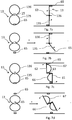
- Figure 6a-6d illustrates a top cross-sectional view of the valve member when having a rotational axle 63, around which the valve member 13 may rotate. The rotation will happen in response to a pressure difference in the first opening relative the second opening.
- the arrows in the figure illustrates in which way the gas should flow for achieving the pressure relief, also indicated by the +/- signs.
- the valve member comprises two portions (as has also been explained in relation to fig. 4b ); an outlet portion 135 for letting out air during pressure levels above said positive pressure P P threshold level and one inlet portion 136 for letting in air in the room volume during pressure levels below the negative pressure P N threshold level.
- the outlet portion 135 is arranged on a first side 61 illustrated on the lower part of the figure 6a , and the inlet portion 136 is arranged on the second side 62 illustrated in the upper part of figure 6a .
- the first side 61 is arranged on an opposite side of the rotational axle 63, relative the second side 62.
- the outlet portion 135 and the inlet portion 136 are formed as latches on the two sides.
- the whole valve member 13 will rotate (clockwise in the figure, but could be any constructed to rotate in any direction) to allow a larger flow of gas from the room volume to faster pressure relief the room relative a pressure outside of the room volume. This is achieved since the pressure on the first side is reduced when the outlet portion opens. This is illustrated in fig 6c .
- the inlet portion 136 would open and thereafter the valve member 13 would rotated (in the same direction in the illustrated example), allowing gas to enter the room volume to achieve the pressure relief.
- valve member 13 may have a connecting portion 64 extending perpendicular to the rotational axle to axially displace the first side 61 from the second side 62.
- the valve member may not have the connection portion, so that the first 61 and second 62 side are axially aligned.
- the form of the pressure regulating device may have e.g. around circumference, or a square formed periphery.
- fig 7a - 7d shows examples where the pressure regulator also comprise a rotational axle 63, around which the valve member 13 may rotate.
- the valve means 13 is illustrated in a front view to the right and in a cross-sectional top view to the left.
- the valve member 13 comprise two portions; an outlet portion 135 for letting out air during pressure levels above said positive pressure threshold level and an inlet portion 136 for letting in air in the room volume during pressure levels below said negative pressure threshold level.
- the outlet portion 135 pivots around the rotational axle 63 without affecting the orientation of the inlet portion 135.
- the inlet portion 135 may be individually pivotable for letting in air during pressure levels below the negative pressure threshold level.
- the two portions may be placed in two separated holes, as individual opposing 1-way valves, cooperating to form a 2-way pressure regulating device. However, they may also be incorporated in the same hole and cooperatively act as the 2-way pressure regulating device.
- the pressure regulating unit 1 in these embodiments may comprise a stopping means 65 for stopping the inlet portion 136 and/or the outlet portion 137 in its closed position. Further, but not illustrated in these figures the pressure regulating unit may comprise returning means 15 of any type of means for bringing the outlet/inlet portion into the closed position. E.g. an electric actuator or a resilient material or device.
- Fig. 7c and 7d are largely analogue with fig 7a/7b , but the outlet/inlet portions are connected to pivot together around the rotating axle 63.
- the valve member 13 comprises an outlet portion 135 for letting out air during pressure levels above said positive pressure P P threshold level and one inlet portion 136 for letting in air in the room volume during pressure levels below the negative pressure P N threshold level.
- the outlet portion 135 is arranged on a first side 61 illustrated on the lower part of the figure 6a
- the inlet portion 136 is arranged on the second side 62 illustrated in the upper part of figure 6a .
- the first side 61 is arranged on an opposite side of the rotational axle 63, relative the second side 62.
- the two portions 135 and 136 are a part of the respective sides 61, 62 and they comprise a first arched surface 66 and a second arched surface 67, respectively.
- the two arched surfaces 66, 67 are thereby arranged on different sides of the rotational axle 63, and the first arched surface 66 is facing the first opening (towards the room volume) and the second arched surface 67 faces the second opening (towards another volume than the room volume).
- the valve member is flat on the radially opposing side 68 relative the first arched surface 66.
- valve member 13 On the axial side facing the second opening the valve member is flat on the radially opposing side 69 relative the second arched surface 67.
- the rotational axle 63 is placed centrally, but even so the valve member 13 will rotate around the central axle 63 as a result of the pressure difference being negative or positive, since the two arched surfaces 66, 67 will have a larger pressurized surface than the flat sides 68, 69 facing the same opening but on the other side of the rotational axle 63.
Abstract
A pressure regulating unit (1) for regulating the pressure resulted from a fire in a room volume (100), comprising a main body (10) having a first opening (11) adapted to be mounted in fluid connection to the inside of said room volume, and a second opening (12) adapted to be mounted in fluid connection to an outside of said room volume. The pressure regulating device further comprise a valve member (13) arranged between said first opening and said second opening, said valve member being movable between a first closed position (A) and a second open position (B). Further, the valve member opens when the pressure in said room volume exceeds a predetermined positive pressure threshold level (P P ) or falls below a predetermined negative pressure threshold level (P L ) and is in said closed position during pressure levels in the room volume being between said positive pressure threshold level and negative pressure threshold level.
Description
- The present invention relates to fire valve units for preventing effects of a fire in a building.
- It is generally known that a fire in a building affects the gaseous pressure so that the pressure initially increases and subsequently decreases relative the atmospheric pressure. This knowledge has primarily been used to study the spreading of gases originating from the fire in ventilation systems. Today's strict construction regulations related to energy efficiency results in that new buildings are basically airtight compartments. The consequence in relation to fires is that the fire heats the air inside the airtight compartment the pressure is dramatically increased, and subsequently the pressure drops since the oxygen level in the compartment limits the fire, resulting in that the temperature (and thereby pressure) in the room drops. Experiments show that pressures may increase to about +1500 Pa and a subsequent decrease in pressure of about -1000 Pa relative the pressure before the fire.
- The inventor has realized that there are a number of problems arising from the pressure fluctuation in a building during a fire. Therefore, there is a need of improving how the buildings handling the pressure during a fire. Specifically, the inventor has realized that the force required for manually opening of doors is directly affected by the pressure in the room, and that the pressure on a door dramatically exceed the construction requirements on forces required to open doors upon a fire. This has even caused deaths during fires, where the victims have been found dead on the inside of the door, since they have not had enough strength to open the door due to the pressure generated by the fire.
- An object of the present invention is to provide a solution that at least alleviated the above mentioned problems related to pressure differences during a fire in a closed room.
- The invention is based on the inventor's insight that by providing a room with an opening to an outside of the room and by installing a 2-way valve device in said opening, the pressure increase and decrease during a fire may be alleviated. Further, by keeping the 2-way valve device closed under normal pressure levels, the strict construction regulations related to energy efficiency may also be met.
- Above-mentioned objects are realized through a pressure regulating unit for regulating the pressure resulted from a fire in a room volume, comprising a main body having a first opening adapted to be mounted in fluid connection to the inside of said room volume, and a second opening adapted to be mounted in fluid connection to an outside of said room volume. The pressure regulating device further comprise a valve member arranged between said first opening and said second opening, said valve member being movable between a first closed position and a second open position. Further, the valve member opens when the pressure in said room volume exceeds a predetermined positive pressure threshold level or falls below a predetermined negative pressure threshold level and is in said closed position during pressure levels in the room volume being between said positive pressure threshold level and negative pressure threshold level. Hereby, a pressure regulating unit may be provided that enables someone who is trapped inside a room with a fire to be able to open the door to exit the room comprising the fire. This invention may therefore save lives.
- In the context of this application, any "in fluid connection" should be understood as a gaseous fluid may flow between the first and second object being in fluid connection.
- In one embodiment, the valve member automatically returns to the closed position when the pressure in said room volume returns to a level that lies between a predetermined positive pressure threshold level and a predetermined negative pressure threshold level. Hereby, the valve member does not have to be repositioned into the closed position manually after an increase in pressure in the room volume.
- In yet one embodiment, the positive pressure threshold level and/or said negative pressure threshold level is calculated based on the force required to evacuate the room, by e.g. opening the door or a window in a room. Hereby, the door/window may always be openable to user.
- In one embodiment the positive pressure threshold level and/or said negative pressure threshold level is at least about 50Pa/-50Pa, least about 100Pa/-100Pa, at least about 150Pa/-150Pa, or at least about 250Pa/-250Pa.
- In yet one embodiment, the valve unit is sized and formed so that the pressure increase/decrease in the room volume alone moves the valve member from the closed position to the open position. Hereby, no electronic equipment such as sensors and/or motors need to be used. It is of course possible to use electronic sensors and motors, but the solution will be much more expensive than a mechanical solution.
- In one embodiment, the valve means is deformable so that it may change from an open state to a closed state and vice versa. In yet one embodiment, the valve means is deformable by means of a flexible material. E.g. a fire proof deformable textile may be used for the valve member.
- In yet one embodiment, the pressure regulating unit further comprise a returning means for returning the valve means from the open position to the closed position.
- In yet one embodiment, the force that the returning means exerts on the valve means for bringing it to, or keeping it in, the closed positon is based on calculations derived from the positive pressure threshold level or negative pressure threshold. E.g. in one embodiment, the force exerted from the returning means on the valve means for bringing it to, or keeping it in, the closed positon corresponds to a force the pressure at either the positive pressure threshold level or negative pressure threshold level exerts on the valve means.
- In yet one embodiment, the returning means is a springing means, such as a spring, coil spring or similar.
- In one embodiment, the valve member comprises an outlet portion for letting out air during pressure levels above said positive pressure threshold level and one inlet portion for letting in air during pressure levels below the negative pressure threshold level.
- In yet one embodiment, the outlet portion is axially displaced relative the inlet portion, so as to create an intermediate insulating volume.
- In another embodiment the outlet portion is juxtaposed arranged relative the inlet portion.
- According to a second aspect of the invention, the above-mention problems are at least partly alleviated by providing a room comprising a plurality of surfaces defining a room volume and restricting flow of gas to/from said room volume, an opening in at least one of said plurality of surfaces, and a pressure regulating unit according to any of above mentioned embodiments. Further, the pressure regulating unit is installed in the opening to allow flow of gas to/from the room to pressure neutralize the room. Hereby, exiting the room during a fire is facilitated.
- In one embodiment the room comprise additional openings in at least one of said plurality of surfaces, and one pressure regulating unit according to any of the above mentioned embodiments installed in each one of said additional openings to allow flow of gas to/from said room to pressure neutralize said room. Hereby, even a large room may be pressure relieved so as to facilitate to exit the room during a fire.
- In one embodiment, the valve member is arranged onto a rotational axle and adapted to rotate between the first closed position and the second open position.
- In yet one embodiment, the valve member's outlet portion for letting out air during pressure levels above said positive pressure threshold level is arranged on a first side of the rotational axle, and the inlet portion for letting in air during pressure levels below the negative pressure threshold level arranged a second side of the rotational axle, being opposite of the first side.
- In one embodiment, the
valve member 13 is adapted to rotate around the rotational axle as a consequence of that the outlet portion is opened, or that the inlet portion is opened. - In one embodiment, the outlet portion for letting out air during pressure levels above said positive pressure threshold level pivots around the rotational axle without affecting the orientation of the inlet portion which may be individually pivotable for letting in air during pressure levels below the negative pressure threshold level.
- In an alternative embodiment, the outlet portion and the inlet portion are coupled so as to move together around the rotational axle, but in opposite rotational directions.
- In one embodiment, at least a portion of the valve member comprise an arched surface. Hereby, even if the rotational axle is placed centrally, the valve member may be designed to rotate around the central axle as a result of the pressure difference.
- In one embodiment, the pressure regulating unit comprise a stopping means for stopping the inlet portion, the outlet portion, and/or the valve member in its stopping position. In some embodiments there may be several stopping means arranged for one or several components.
- In one embodiment, at least two portions of the valve member comprise an arched surface, wherein the arched surfaces are arranged on different sides of the rotational axle, and one of the facing the first opening and the other one facing the second opening. Hereby, even if the rotational axle is placed centrally, the valve member may be designed to rotate around the central axle as a result of the pressure difference being both negative or positive.
- All the embodiments mentioned above may be combined with each other, unless having obviously non-compatible designs.
- Further details and aspect of the present invention will become apparent from the following detailed description with reference to accompanying drawings, in which:
-
fig. 1 shows an illustration of a pressure regulating unit according to one embodiment of the invention, -
fig. 2 shows a top view of an illustration of a room in which a fire is burning and a pressure regulating unit is installed, -
fig. 3 shows a graph over the pressure over time during a fire in a closed room, -
fig. 4a-4d shows the valve member according to four embodiments, wherein each figure shows a front view and a side cross-sectional view of the embodiment, and -
fig. 5a-5d shows the valve member according to four embodiments, wherein each figure shows a front view and a side cross-sectional view of the embodiment, -
Fig. 6a-6d illustrates a top cross-sectional view of the valve member according to one embodiment, and how it reacts to pressure differences, and -
Fig. 7a-7d illustrates front views and top cross-sectional views of the valve member according to one embodiment, and how it reacts to pressure differences. - The present invention will now be described more fully hereinafter with reference to the accompanying drawings, in which currently preferred embodiments of the invention are shown. This invention may, however, be embodied in many different forms and should not be construed as limited to the embodiments set forth herein; rather, these embodiments are provided for thoroughness and completeness, and fully convey the scope of the invention to the skilled addressee. Like reference characters refer to like elements throughout the application. When the same elements are repeatedly shown in a figure, not all such elements are specifically referred to with reference characters.
-
Fig. 1 illustrate apressure regulating unit 1 according to one embodiment of the invention, wherein thepressure regulating unit 1 comprise amain body 10. In this illustration the main body is circular. The main body shape may however be of any shape, as long as the shape fits into a hole in one of the walls/roof/ceiling in the room. An advantage with a circular, tube formedmain body 10 is that the hole may be easily achieved by a hole saw with a diameter corresponding to the outer diameter of the main body. - The outer diameter may be chosen so that enough air may flow though the
pressure regulating unit 1, to pressure relief the room volume during a fire. E.g. the outer diameter may be about 50-500mm, or preferably about 100-250mm or most preferably about 130-200mm. - Further, the
main body 10 comprise afirst opening 11 and asecond opening 12. Thefirst opening 11 is to be installed towards the inside of the room volume, and thesecond opening 12 towards an outside of the room. Hereby, the main body fluidly connects the room volume with a volume outside of the room. Preferably, the outside of the room is directly or indirectly connected to the outside of a building, so that an efficient pressure relief may be achieved. - Further,
fig 1 illustrates that the pressure regulating unit comprise avalve member 13. Thevalve member 13 is adapted to move from a first closed position A to a second open position B (not shown infig 1 ). This is further explained whenfigures 4-5 are described below. When thevalve member 13 is in the closed position A, the room volume may be substantially closed, so at to meet the energy efficiency regulations. -
fig. 2 shows a top view of an illustration of aroom 100 defining a room volume. Afire 101 is burning inside the room and apressure regulating unit 1 is installed in one of thewalls 102. Also, adoor 103 is illustrated in the room. The pressure regulating unit may of course be arranged in any wall and/or ceiling or even floor of the room. If the room is large, it may be advantageous to have a plurality of pressure regulating units in the room volume. Also, if there are dividing walls inside a room, having apressure regulating unit 1 installed in each portion of the room may be beneficial, especially if there are doors that would be opened to exit the room, in case of a fire. - Further,
fig. 3 shows a graph P(t) illustrating the pressure difference over time during a fire in a closed room. The initial pressure is starting at a point wherein the pressure on the inside of the room is about the same as the pressure on the outside of the room. This starting pressure may be e.g. 1 bar (about 100 000 Pa). The graph is generated from data during measurements in fires in closed rooms conducted by the applicant. In the experiments a fluid heptane was lit in a room volume while measuring the pressure in the room during the fire development in the room. As can be seen from this graph, when a fire takes place in the room, within less than one minute the relative pressure increase to a level above the denoted positive pressure threshold level PP. This pressure level is denoted as a dashed upper line and as about +100Pa in the illustration. If the door has a surface of 2m2 the force acting on the door is 200N at +100Pa increase in pressure relative the outside. Since the door is usually hinged at one side and has a handle at the opposite side, the force for opening the door is about half the force of the force acting on the door. That is, for +100 Pa the force for opening the door is about 100N. - Further, a negative pressure threshold level PN is denoted as the dashed lower line and as about -100Pa in the graph. Two striped areas PH, PL indicating when the pressure is either higher PH than the positive pressure threshold level PP, or lower PL than the predetermined negative pressure threshold level PN is denoted in the graph. The high pressure range PH is reached already within the minute of the fire in the measurements. Before the high pressure range PH is reached, it is possible to open the door, illustrated by an opening pressure Po corresponding to the pressure in the room when the door is openable with manpower (or according to construction regulations). The time during which the pressure in the room corresponds to an opening pressure Po is denoted in the graph.
- After the high pressure range PH is over, after about 3 minutes (when the oxygen level is too low for the fire to continue to grow), there is a new window of opportunity to open the door again, when the pressure in the room is back to the opening pressure Po, and before the pressure drops below the predetermined negative pressure threshold level PN.
- Thereafter, the pressure drops below the predetermined negative pressure threshold level PN again and the force required to open the door is higher than can be expected by most people and/or higher than regulations require. The positive pressure threshold level PP and the negative pressure threshold level PN may be chosen so that the valve opens corresponding to a desired force level for opening the door.
- By introducing the pressure regulating unit into the room, the variation of pressure as a function over time may be reduced. In fact, although there will be a pressure increase and decrease, the maximum increase may be kept in pressure levels around the positive pressure threshold level PP. Further the maximum negative pressure drop may be kept within the negative pressure threshold level PN. Hereby, the door may be openable throughout the fire in the room.
- Moreover,
fig. 4a-4d shows the valve member according to four different embodiments, wherein each figure shows a front view and a side view of the embodiment.Fig 4a show avalve member 13 having amovable restriction device 131. Therestriction device 131 is closed during normal pressure Po levels, corresponding to the pressure outside of the room. Further therestriction device 131 opens upon a pressure difference either exceeding the positive pressure threshold level PP or falling below the negative pressure threshold level PN. Infig. 4a therestriction device 131 is pivotably arranged in its top portion, and arranged within thevalve member 13. The restriction device may pivot in a first direction to allow flow out of the room volume and in a second direction to allow flow into the room volume. Although not illustrated, the restriction device may be resiliently arranged so as to return to its closed position during a pressure Po being in between the positive pressure threshold level PP and the negative pressure threshold level PN. Further, the restriction device may return to its closed position by merely gravitation if the pivotal arrangement is arranged in its top portion. Hereby, the weight of the restriction device will pull it into the closed position, when being pushed by the increased/decreased pressure inside the room. Further, the right part of the figure show how air can pass through thevalve member 13 in an open state. The arrows in respective direction indicates the movement of therestriction member 131 to allow inlet flow and outlet flow, respectively. - Further,
fig 4b disclose thevalve member 13 being divided into anoutlet portion 135 for letting out air during pressure levels above said positive pressure PP threshold level and oneinlet portion 136 for letting in air in the room volume during pressure levels below the negative pressure PN threshold level. To the left in the figure a front side illustration is shown, where theinlet portion 136 comprise a returningmeans 15, in this case being in the form of a coil spring. The returning means 15 is also shown in the side view to the right, and there it is shown that theoutlet portion 135 also comprise a returning means 15 in the form of a coil spring. The returning means 15 may be any type of means for bringing the inlet portion into the closed position. E.g. an electric actuator or a resilient material or device. Depending on the form of the returning means it may be provided on the opening side of the inlet/outlet portion so as to push the portion back into the closed position, it can also be provided on the opposite side so as to pull the portion back into the closed position. As has been explained above, in relation to therestriction device 131, theinlet portion 136 and oroutlet portion 135 may return to its closed position by merely gravitation if the pivotal arrangement is arranged in its top portion. Further, thepressure regulating unit 1 may comprise a stopping means 65 for stopping theinlet portion 136 and/or theoutlet portion 137 in its closed position, so that the returning means 15 hold the inlet portion or outlet portion against said stopping means. Said stopping means may be a projection from themain body 10. As infigure 4a , the right part offig 4b show how air can pass through thevalve member 13 in an open state. The arrows in respective direction indicates the movement of the valve member (inlet and outlet portions) to allow inlet flow and outlet flow, respectively. -
Fig 4c illustrates avalve member 13, having a similar set-up as infig 4a , but with a round outer form instead of a rectangular outer form. Also, the restrictingdevice 131 is round in the embodiment disclosed infig 4c . - Correspondingly,
Fig 4d illustrates avalve member 13, having a similar set-up as infig 4b , but with a round outer form instead of a rectangular outer form. -
fig. 5a-5d shows the valve member according to four different embodiments, wherein each figure shows a front view and a side view of the embodiment. Infigure 5a-5b the valve means 13 is aflexible material 137 being deformable. For example, the flexible material may be a fire proof deformable textile. - The illustrated
flexible material 137 is designed to open in response to a pressure difference in the room volume relative the pressure outside of the room volume. The left illustrations in bothfig. 5a and 5b illustrates cross-sectional end views of the valve means 13. Theflexible material 137 may either be in a closed state A or an open state B. During the open states B theflexible material 137 may either be in an inlet position or an outlet position, depending on if there is a positive or negative pressure in the room volume that is to be pressure relieved. - The
flexible material 137 is attached, either directly or indirectly, to themain body 10 of thepressure regulating unit 1. Theflexible material 137 may be attached to themain body 10 by means of a holdingmember 138, e.g. being a plastic tube holding theflexible material 137 to themain body 10. - Further, at an end of the flexible material an
elastic member 139 is illustrated. The elastic member is arranged to close theflexible material 137 when the pressure in the room volume is between the positive pressure threshold level and the negative pressure threshold level, which is illustrated infig 5a and 5b in the illustrations marked "A". - If the pressure increase above the positive pressure threshold level the
elastic member 139 expands so as to open theflexible material 137 and thereby allow an outlet flow of gas from said room volume. This is shown in bothfigure 5a and 5b in the first versions marked with "B". Further, if the pressure drops below the negative pressure threshold level theelastic member 139 expands so as to open theflexible material 137 to allow an inlet flow of gas from said room volume. This is illustrated by the other open state figures (marked with B) offig 5a and 5b . - In
fig 5a a single valve member is used and infig. 5b two portions of the valve member is used, afirst portion 137a and asecond portion 137b. The first and second portions are serially arranged in the flow direction and are identical in the illustration. It is however possible to make the first and second portion with different configurations e.g. by having different elasticity in the elastic parts in order to control the flow of gas through the two portions. One advantage with having a first 137a and a serially arranged second 137b portion is that an intermediateinsulating volume 140 is created between the first and second portions when they are in the closed state A as shown infig 5b . This vastly increase the insulating capability to the device. - In
fig 5c the valve member is asingle valve member 13 that is pivotable in two different directions, the first direction as a response to that the pressure in the room volume drops below the negative pressure threshold level PN, and the second direction as a response to to that the pressure in the room volume exceed the positive pressure threshold level PP. - Further, in
fig. 5d the valve member comprises two valve portions 135,136, wherein anoutlet portion 135 for letting out air during pressure levels above said positive pressure threshold level PP and oneinlet portion 136 for letting in air during pressure levels below the negative pressure PN threshold level. The mechanical function of respective portion is the same as infig 5c , where theinlet portion 136 pivots in an inward direction as a response to that the pressure in the room volume drops below the negative pressure threshold level PN, and theoutlet portion 135 pivots in an outward direction as a response to to that the pressure in the room volume exceed the positive pressure threshold level PP. Hereby, pressure relief is made possible in two juxtaposed valve portions, one arranged for each direction of flow. -
Figure 6a-6d illustrates a top cross-sectional view of the valve member when having arotational axle 63, around which thevalve member 13 may rotate. The rotation will happen in response to a pressure difference in the first opening relative the second opening. The arrows in the figure illustrates in which way the gas should flow for achieving the pressure relief, also indicated by the +/- signs. The valve member comprises two portions (as has also been explained in relation tofig. 4b ); anoutlet portion 135 for letting out air during pressure levels above said positive pressure PP threshold level and oneinlet portion 136 for letting in air in the room volume during pressure levels below the negative pressure PN threshold level. Theoutlet portion 135 is arranged on afirst side 61 illustrated on the lower part of thefigure 6a , and theinlet portion 136 is arranged on thesecond side 62 illustrated in the upper part offigure 6a . Thefirst side 61 is arranged on an opposite side of therotational axle 63, relative thesecond side 62. Moreover, theoutlet portion 135 and theinlet portion 136 are formed as latches on the two sides. When a pressure increase inside the room volume increase above the positive pressure PP threshold value, theoutlet portion 135 will open to let air out, as is illustrated infig 6b . Further, as a consequence of that theoutlet portion 135 opens, thewhole valve member 13 will rotate (clockwise in the figure, but could be any constructed to rotate in any direction) to allow a larger flow of gas from the room volume to faster pressure relief the room relative a pressure outside of the room volume. This is achieved since the pressure on the first side is reduced when the outlet portion opens. This is illustrated infig 6c . - Further, if the pressure in the room volume falls below the negative pressure PN threshold level the
inlet portion 136 would open and thereafter thevalve member 13 would rotated (in the same direction in the illustrated example), allowing gas to enter the room volume to achieve the pressure relief. - Moreover, the
valve member 13 may have a connectingportion 64 extending perpendicular to the rotational axle to axially displace thefirst side 61 from thesecond side 62. However, the valve member may not have the connection portion, so that the first 61 and second 62 side are axially aligned. - Further, as already explained in relation to the above embodiments which in large are fully compatible with the embodiment in
fig. 6a-6d , the form of the pressure regulating device may have e.g. around circumference, or a square formed periphery. - Moving on to the final set of figures,
fig 7a - 7d shows examples where the pressure regulator also comprise arotational axle 63, around which thevalve member 13 may rotate. In the illustrations the valve means 13 is illustrated in a front view to the right and in a cross-sectional top view to the left. Infig 7a and 7b thevalve member 13 comprise two portions; anoutlet portion 135 for letting out air during pressure levels above said positive pressure threshold level and aninlet portion 136 for letting in air in the room volume during pressure levels below said negative pressure threshold level. Theoutlet portion 135 pivots around therotational axle 63 without affecting the orientation of theinlet portion 135. Likewise, theinlet portion 135 may be individually pivotable for letting in air during pressure levels below the negative pressure threshold level. The two portions may be placed in two separated holes, as individual opposing 1-way valves, cooperating to form a 2-way pressure regulating device. However, they may also be incorporated in the same hole and cooperatively act as the 2-way pressure regulating device. - Also, the
pressure regulating unit 1 in these embodiments (in any of the embodiments) may comprise a stopping means 65 for stopping theinlet portion 136 and/or theoutlet portion 137 in its closed position. Further, but not illustrated in these figures the pressure regulating unit may comprise returningmeans 15 of any type of means for bringing the outlet/inlet portion into the closed position. E.g. an electric actuator or a resilient material or device. - Further, in
fig. 7a both the outlet and inlet portions are closed, and held against the stop. InFig 7b , theoutlet portion 135 is opened to allow a flow of gas out from the room volume. This is hard to see in the front view (but you can tell that the outlet portion does not seem to be entirely circular, but in the side view the opening is clearly illustrated. -
Fig. 7c and 7d are largely analogue withfig 7a/7b , but the outlet/inlet portions are connected to pivot together around the rotatingaxle 63. As in the above examples, thevalve member 13 comprises anoutlet portion 135 for letting out air during pressure levels above said positive pressure PP threshold level and oneinlet portion 136 for letting in air in the room volume during pressure levels below the negative pressure PN threshold level. Theoutlet portion 135 is arranged on afirst side 61 illustrated on the lower part of thefigure 6a , and theinlet portion 136 is arranged on thesecond side 62 illustrated in the upper part offigure 6a . Thefirst side 61 is arranged on an opposite side of therotational axle 63, relative thesecond side 62. Moreover, not illustrated before, in thevalve member 13 illustrated infig 7c and 7d , the twoportions respective sides arched surface 66 and a secondarched surface 67, respectively. The twoarched surfaces rotational axle 63, and the firstarched surface 66 is facing the first opening (towards the room volume) and the secondarched surface 67 faces the second opening (towards another volume than the room volume). On the axial side facing the first opening the valve member is flat on the radially opposing side 68 relative the firstarched surface 66. Likewise, on the axial side facing the second opening the valve member is flat on the radially opposing side 69 relative the secondarched surface 67. Therotational axle 63 is placed centrally, but even so thevalve member 13 will rotate around thecentral axle 63 as a result of the pressure difference being negative or positive, since the twoarched surfaces rotational axle 63.
Claims (15)
- A pressure regulating unit (1) for regulating the pressure resulted from a fire in a room (100) volume, comprising:- a main body (10) comprising a first opening (11) adapted to be mounted in fluid connection to the inside of said room volume, and a second opening (12) adapted to be mounted in fluid connection to an outside of said room volume, and- a valve member (13) arranged between said first opening and said second opening, said valve member being movable between a first closed position (A) and a second open position (B), whereinsaid valve member opens when the pressure in said room volume exceeds a predetermined positive pressure (PP) threshold level or falls below a predetermined negative pressure (PN) threshold level and is in said closed position during pressure levels in the room volume being between said positive pressure threshold level and negative pressure threshold level.
- The pressure regulating unit (1) according to claim 1, wherein said valve member (13) automatically returns to the closed position when the pressure in said room volume returns to a level that lies between a predetermined positive pressure threshold level (PP) and a predetermined negative pressure (PN) threshold level.
- The pressure regulating unit (1) according to any one of claims 1-2, wherein said positive pressure threshold level and/or said negative pressure threshold level is calculated based on the force required to evacuate the room volume, by opening a door or a window.
- The pressure regulating unit (1) according to any one of claims 1-3, wherein said positive pressure threshold level and/or said negative pressure threshold level is at least about 50Pa/-50Pa, least about 100Pa/-100Pa, at least about 150Pa/-150Pa, or at least about 250Pa/- 250Pa.
- The pressure regulating unit (1) according to any of the preceding claims, wherein the valve unit (13) is sized and formed so that the pressure increase/decrease in the room volume alone moves the valve member (13) from the closed position (A) to the open position (B).
- The pressure regulating unit (1) according to any of the preceding claims, wherein the valve means (13) is deformable so that it may change from an open state to a closed state and vice versa.
- The pressure regulating unit (1) according to Claim 6, wherein the valve means (13) is deformable by means of a flexible material.
- The pressure regulating unit (1) according to any of the preceding claims, further comprising a returning means (15) for returning the valve means (13) from the open position to the closed position.
- The pressure regulating unit (1) according to claims 1-9, wherein the force the returning means (15) exerts on the valve means (13) for bringing it to, or keeping it in, the closed positon is based on calculations derived from the positive pressure threshold level or negative pressure threshold level.
- The pressure regulating unit (1) according to claim 8 or 9, wherein the returning means (15) is a springing means, such as a spring, coil spring or similar.
- The pressure regulating unit (1) according to any of the preceding claims, wherein the valve member (13) comprise an outlet portion for letting out air during pressure levels above said positive pressure threshold level and one inlet portion for letting in air during pressure levels below the negative pressure threshold level.
- The pressure regulating unit (1) according to claim 11, wherein the outlet portion is juxtaposed arranged relative the inlet portion.
- The pressure regulating unit (1) according to any of the preceding claims, wherein the valve member (13) comprise two portions (137a, 137b) being axially displaced relative each other, so as to create an intermediate insulating volume (140).
- A room (100) comprising- a plurality of surfaces defining a room volume and restricting flow of gas to/from said room volume,- an opening in at least one of said plurality of surfaces, and- a pressure regulating unit according to any of claims 1-13, wherein said pressure regulating unit is installed in said opening to allow flow of gas to/from said room so as to pressure neutralize said room.
- A room according to claim14, further comprising additional openings in at least one of said plurality of surfaces, and one pressure regulating unit according to any of claims 1-13 installed in each one of said additional openings to allow flow of gas to/from said room so as to pressure neutralize said room.
Priority Applications (1)
| Application Number | Priority Date | Filing Date | Title |
|---|---|---|---|
| EP17162064.4A EP3378538A1 (en) | 2017-03-21 | 2017-03-21 | A pressure regulating unit for regulating pressure resulted from a fire in a room |
Applications Claiming Priority (1)
| Application Number | Priority Date | Filing Date | Title |
|---|---|---|---|
| EP17162064.4A EP3378538A1 (en) | 2017-03-21 | 2017-03-21 | A pressure regulating unit for regulating pressure resulted from a fire in a room |
Publications (1)
| Publication Number | Publication Date |
|---|---|
| EP3378538A1 true EP3378538A1 (en) | 2018-09-26 |
Family
ID=58401424
Family Applications (1)
| Application Number | Title | Priority Date | Filing Date |
|---|---|---|---|
| EP17162064.4A Withdrawn EP3378538A1 (en) | 2017-03-21 | 2017-03-21 | A pressure regulating unit for regulating pressure resulted from a fire in a room |
Country Status (1)
| Country | Link |
|---|---|
| EP (1) | EP3378538A1 (en) |
Cited By (3)
| Publication number | Priority date | Publication date | Assignee | Title |
|---|---|---|---|---|
| CN109839878A (en) * | 2019-03-04 | 2019-06-04 | 江苏荣夏安全科技有限公司 | Fire-fighting emergent evacuates overbottom pressure monitoring method and system |
| CN113768644A (en) * | 2021-09-17 | 2021-12-10 | 福州金典工业产品设计有限公司 | Spray head structure of tooth flushing device and design method thereof |
| GB2598197A (en) * | 2020-07-03 | 2022-02-23 | Afp Air Tech Ltd | Modular pressure relief dampers |
Citations (4)
| Publication number | Priority date | Publication date | Assignee | Title |
|---|---|---|---|---|
| US3011518A (en) * | 1958-07-09 | 1961-12-05 | Connor Eng Corp | Pneumatic damper |
| WO2010061216A1 (en) * | 2008-11-25 | 2010-06-03 | Christopher Coxon | A pressure relief vent |
| WO2011010140A1 (en) * | 2009-07-21 | 2011-01-27 | Apreco Limited | Venting device |
| GB2540356A (en) * | 2015-07-13 | 2017-01-18 | Afp Air Tech Ltd | Two way pressure relief vent |
-
2017
- 2017-03-21 EP EP17162064.4A patent/EP3378538A1/en not_active Withdrawn
Patent Citations (4)
| Publication number | Priority date | Publication date | Assignee | Title |
|---|---|---|---|---|
| US3011518A (en) * | 1958-07-09 | 1961-12-05 | Connor Eng Corp | Pneumatic damper |
| WO2010061216A1 (en) * | 2008-11-25 | 2010-06-03 | Christopher Coxon | A pressure relief vent |
| WO2011010140A1 (en) * | 2009-07-21 | 2011-01-27 | Apreco Limited | Venting device |
| GB2540356A (en) * | 2015-07-13 | 2017-01-18 | Afp Air Tech Ltd | Two way pressure relief vent |
Cited By (5)
| Publication number | Priority date | Publication date | Assignee | Title |
|---|---|---|---|---|
| CN109839878A (en) * | 2019-03-04 | 2019-06-04 | 江苏荣夏安全科技有限公司 | Fire-fighting emergent evacuates overbottom pressure monitoring method and system |
| GB2598197A (en) * | 2020-07-03 | 2022-02-23 | Afp Air Tech Ltd | Modular pressure relief dampers |
| GB2598197B (en) * | 2020-07-03 | 2022-08-10 | Afp Air Tech Ltd | Modular pressure relief dampers |
| CN113768644A (en) * | 2021-09-17 | 2021-12-10 | 福州金典工业产品设计有限公司 | Spray head structure of tooth flushing device and design method thereof |
| CN113768644B (en) * | 2021-09-17 | 2024-02-20 | 福州牙宜生口腔科技有限公司 | Tooth-flushing device nozzle structure and design method thereof |
Similar Documents
| Publication | Publication Date | Title |
|---|---|---|
| EP3378538A1 (en) | A pressure regulating unit for regulating pressure resulted from a fire in a room | |
| KR101423989B1 (en) | A two-way release damper of gas system fire extinguishing system | |
| KR102456188B1 (en) | Blast valves with aerodynamically configured blades | |
| KR101610281B1 (en) | Dual-Mode Controller for smoke dampers and control method of air supply | |
| KR102058079B1 (en) | Smoke extraction system with ventilation and fire suppression damper | |
| KR101303332B1 (en) | Relief damper and smoke control system with providing pressurized air thereof | |
| US3521546A (en) | Atmospheric pressure equalizing means | |
| KR200423332Y1 (en) | Damper for fire and air control of building ventilation duct | |
| GB2540356A (en) | Two way pressure relief vent | |
| US6019679A (en) | Fire and smoke damper | |
| KR101389159B1 (en) | Air pressure regulating apparatus for interior of a building | |
| US4557185A (en) | Solenoid operated exhaust air damper | |
| KR100932292B1 (en) | Pressure regulating backflow damper | |
| CN108979476B (en) | Daylighting type intelligence is let out and is exploded window | |
| EP2971995A1 (en) | Arrangement for pressurizing a space and/or evacuating smoke therefrom in case of a fire | |
| US4094332A (en) | Earthquake-responsive fuel shut-off device | |
| KR101525186B1 (en) | Exhaust smoke damper | |
| KR101812506B1 (en) | Door Closer Closing Force Auxiliary Device in Smoking-Proof Area and the Operation Method thereof | |
| KR101701085B1 (en) | Emergency escape door of fireproof shutter | |
| EP3308086B1 (en) | Compensation valve for environments having a pressure different from the atmospheric one | |
| SE542062C2 (en) | A pressure regulating unit for regulating pressure resulted from a fire in a room | |
| KR101507367B1 (en) | Equipped with a plurality of damper adjustable airflow diffuser for air conditioning unit | |
| CN108952506B (en) | Heat preservation type intelligence is let out and is exploded window | |
| US3072041A (en) | Fans | |
| KR101194721B1 (en) | Back flow prevention device of air supply diffuser |
Legal Events
| Date | Code | Title | Description |
|---|---|---|---|
| PUAI | Public reference made under article 153(3) epc to a published international application that has entered the european phase |
Free format text: ORIGINAL CODE: 0009012 |
|
| AK | Designated contracting states |
Kind code of ref document: A1 Designated state(s): AL AT BE BG CH CY CZ DE DK EE ES FI FR GB GR HR HU IE IS IT LI LT LU LV MC MK MT NL NO PL PT RO RS SE SI SK SM TR |
|
| AX | Request for extension of the european patent |
Extension state: BA ME |
|
| STAA | Information on the status of an ep patent application or granted ep patent |
Free format text: STATUS: THE APPLICATION IS DEEMED TO BE WITHDRAWN |
|
| 18D | Application deemed to be withdrawn |
Effective date: 20190327 |