EP3378169B1 - Création de rapport dans différentes dimensions - Google Patents
Création de rapport dans différentes dimensions Download PDFInfo
- Publication number
- EP3378169B1 EP3378169B1 EP16804924.5A EP16804924A EP3378169B1 EP 3378169 B1 EP3378169 B1 EP 3378169B1 EP 16804924 A EP16804924 A EP 16804924A EP 3378169 B1 EP3378169 B1 EP 3378169B1
- Authority
- EP
- European Patent Office
- Prior art keywords
- transmission information
- reporting
- angular transmission
- timing
- terminal
- Prior art date
- Legal status (The legal status is an assumption and is not a legal conclusion. Google has not performed a legal analysis and makes no representation as to the accuracy of the status listed.)
- Active
Links
- 230000005540 biological transmission Effects 0.000 claims description 167
- 238000004891 communication Methods 0.000 claims description 63
- 238000000034 method Methods 0.000 claims description 52
- 239000011159 matrix material Substances 0.000 claims description 28
- 238000004590 computer program Methods 0.000 claims 2
- 238000005259 measurement Methods 0.000 description 18
- 239000010410 layer Substances 0.000 description 15
- 230000011664 signaling Effects 0.000 description 15
- 230000000737 periodic effect Effects 0.000 description 14
- 238000005516 engineering process Methods 0.000 description 12
- 238000013459 approach Methods 0.000 description 11
- 230000009471 action Effects 0.000 description 10
- 239000013598 vector Substances 0.000 description 8
- 238000003491 array Methods 0.000 description 7
- 230000010267 cellular communication Effects 0.000 description 7
- 230000006399 behavior Effects 0.000 description 6
- 239000000969 carrier Substances 0.000 description 5
- 230000001413 cellular effect Effects 0.000 description 5
- 230000006870 function Effects 0.000 description 5
- 230000010287 polarization Effects 0.000 description 5
- 230000008569 process Effects 0.000 description 5
- 238000001228 spectrum Methods 0.000 description 5
- 238000011156 evaluation Methods 0.000 description 4
- 230000007774 longterm Effects 0.000 description 4
- 238000007726 management method Methods 0.000 description 4
- 238000013507 mapping Methods 0.000 description 4
- 241000700159 Rattus Species 0.000 description 3
- 230000008901 benefit Effects 0.000 description 3
- 239000000306 component Substances 0.000 description 3
- 125000004122 cyclic group Chemical group 0.000 description 3
- 230000001419 dependent effect Effects 0.000 description 3
- 238000011161 development Methods 0.000 description 3
- 230000018109 developmental process Effects 0.000 description 3
- 230000009977 dual effect Effects 0.000 description 3
- 238000013468 resource allocation Methods 0.000 description 3
- 230000003595 spectral effect Effects 0.000 description 3
- 238000010586 diagram Methods 0.000 description 2
- 230000007246 mechanism Effects 0.000 description 2
- 238000010295 mobile communication Methods 0.000 description 2
- 230000003287 optical effect Effects 0.000 description 2
- 238000012545 processing Methods 0.000 description 2
- 238000012546 transfer Methods 0.000 description 2
- 238000012935 Averaging Methods 0.000 description 1
- 101100465000 Mus musculus Prag1 gene Proteins 0.000 description 1
- 230000003321 amplification Effects 0.000 description 1
- 230000009286 beneficial effect Effects 0.000 description 1
- 238000004364 calculation method Methods 0.000 description 1
- 230000008859 change Effects 0.000 description 1
- 230000001427 coherent effect Effects 0.000 description 1
- 238000012790 confirmation Methods 0.000 description 1
- 238000010276 construction Methods 0.000 description 1
- 239000008358 core component Substances 0.000 description 1
- 230000008878 coupling Effects 0.000 description 1
- 238000010168 coupling process Methods 0.000 description 1
- 238000005859 coupling reaction Methods 0.000 description 1
- 230000000694 effects Effects 0.000 description 1
- 230000005672 electromagnetic field Effects 0.000 description 1
- 230000002349 favourable effect Effects 0.000 description 1
- 239000003365 glass fiber Substances 0.000 description 1
- 239000011229 interlayer Substances 0.000 description 1
- 238000012423 maintenance Methods 0.000 description 1
- 239000000463 material Substances 0.000 description 1
- 238000003199 nucleic acid amplification method Methods 0.000 description 1
- 230000005855 radiation Effects 0.000 description 1
- 239000002356 single layer Substances 0.000 description 1
- 230000001360 synchronised effect Effects 0.000 description 1
- 238000012360 testing method Methods 0.000 description 1
- 238000002834 transmittance Methods 0.000 description 1
- 230000001960 triggered effect Effects 0.000 description 1
Images


Classifications
-
- H—ELECTRICITY
- H04—ELECTRIC COMMUNICATION TECHNIQUE
- H04B—TRANSMISSION
- H04B7/00—Radio transmission systems, i.e. using radiation field
- H04B7/02—Diversity systems; Multi-antenna system, i.e. transmission or reception using multiple antennas
- H04B7/04—Diversity systems; Multi-antenna system, i.e. transmission or reception using multiple antennas using two or more spaced independent antennas
- H04B7/06—Diversity systems; Multi-antenna system, i.e. transmission or reception using multiple antennas using two or more spaced independent antennas at the transmitting station
- H04B7/0613—Diversity systems; Multi-antenna system, i.e. transmission or reception using multiple antennas using two or more spaced independent antennas at the transmitting station using simultaneous transmission
- H04B7/0615—Diversity systems; Multi-antenna system, i.e. transmission or reception using multiple antennas using two or more spaced independent antennas at the transmitting station using simultaneous transmission of weighted versions of same signal
- H04B7/0617—Diversity systems; Multi-antenna system, i.e. transmission or reception using multiple antennas using two or more spaced independent antennas at the transmitting station using simultaneous transmission of weighted versions of same signal for beam forming
-
- H—ELECTRICITY
- H04—ELECTRIC COMMUNICATION TECHNIQUE
- H04B—TRANSMISSION
- H04B17/00—Monitoring; Testing
- H04B17/10—Monitoring; Testing of transmitters
- H04B17/101—Monitoring; Testing of transmitters for measurement of specific parameters of the transmitter or components thereof
- H04B17/104—Monitoring; Testing of transmitters for measurement of specific parameters of the transmitter or components thereof of other parameters, e.g. DC offset, delay or propagation times
-
- H—ELECTRICITY
- H04—ELECTRIC COMMUNICATION TECHNIQUE
- H04B—TRANSMISSION
- H04B7/00—Radio transmission systems, i.e. using radiation field
- H04B7/02—Diversity systems; Multi-antenna system, i.e. transmission or reception using multiple antennas
- H04B7/04—Diversity systems; Multi-antenna system, i.e. transmission or reception using multiple antennas using two or more spaced independent antennas
- H04B7/0413—MIMO systems
- H04B7/0456—Selection of precoding matrices or codebooks, e.g. using matrices antenna weighting
- H04B7/0478—Special codebook structures directed to feedback optimisation
- H04B7/0479—Special codebook structures directed to feedback optimisation for multi-dimensional arrays, e.g. horizontal or vertical pre-distortion matrix index [PMI]
-
- H—ELECTRICITY
- H04—ELECTRIC COMMUNICATION TECHNIQUE
- H04B—TRANSMISSION
- H04B7/00—Radio transmission systems, i.e. using radiation field
- H04B7/02—Diversity systems; Multi-antenna system, i.e. transmission or reception using multiple antennas
- H04B7/04—Diversity systems; Multi-antenna system, i.e. transmission or reception using multiple antennas using two or more spaced independent antennas
- H04B7/06—Diversity systems; Multi-antenna system, i.e. transmission or reception using multiple antennas using two or more spaced independent antennas at the transmitting station
- H04B7/0613—Diversity systems; Multi-antenna system, i.e. transmission or reception using multiple antennas using two or more spaced independent antennas at the transmitting station using simultaneous transmission
- H04B7/0615—Diversity systems; Multi-antenna system, i.e. transmission or reception using multiple antennas using two or more spaced independent antennas at the transmitting station using simultaneous transmission of weighted versions of same signal
- H04B7/0619—Diversity systems; Multi-antenna system, i.e. transmission or reception using multiple antennas using two or more spaced independent antennas at the transmitting station using simultaneous transmission of weighted versions of same signal using feedback from receiving side
-
- H—ELECTRICITY
- H04—ELECTRIC COMMUNICATION TECHNIQUE
- H04W—WIRELESS COMMUNICATION NETWORKS
- H04W24/00—Supervisory, monitoring or testing arrangements
- H04W24/10—Scheduling measurement reports ; Arrangements for measurement reports
Definitions
- the present disclosure pertains to wireless communication technology, in particular in the context of a Radio Access Network, e.g. according to 3GPP LTE (Long Term Evolution) and/or NR (New Radio) standardization.
- 3GPP LTE Long Term Evolution
- NR New Radio
- Wireless communication technology increasingly utilises multiple antenna arrays for transmission and reception, e.g. for beamforming.
- the radiation profiles received from such antenna arrays e.g. caused by using different sets of antenna elements of such arrays, and their development in time, can be quite anisotropic, e.g. showing very different behaviour in different angular regimes, e.g. in horizontal angles and vertical angles.
- a terminal receiving transmissions from an antenna array e.g., used by a base station or network node
- Document US 2014/192917 A1 discloses a method for operating a terminal in a wireless communication network, the method comprising performing reporting based on a configuration, the configuration indicating the timing of reporting of first angular transmission information and indicating the timing of reporting of second angular transmission information.
- the method comprises performing reporting based on a configuration, the configuration indicating a first timing of reporting of first angular transmission information and indicating a second timing of reporting of second angular transmission information.
- the first timing is different from the second timing.
- the first angular transmission information pertains to a quicker varying angular transmission information.
- the reporting of the first angular transmission information is performed more often and/or quicker than the reporting of the second angular transmission information.
- the first angular transmission information comprises a beam group indicator jointly encoded with a precoding matrix indicator.
- a terminal for a wireless communication network is adapted for performing reporting based on a configuration, the configuration indicating a first timing of reporting of first angular transmission information and indicating a second timing of reporting of second angular transmission information.
- the first timing is different from the second timing.
- the first angular transmission information pertains to a quicker varying angular transmission information.
- the reporting of the first angular transmission information is performed more often and/or quicker than the reporting of the second angular transmission information.
- the first angular transmission information comprises a beam group indicator jointly encoded with a precoding matrix indicator.
- a method for operating a network node in a wireless communication network may be considered.
- the method comprises configuring a terminal for performing reporting based on a configuration, the configuration indicating a first timing of reporting of first angular transmission information and a second timing of reporting of second angular transmission information.
- the first timing is different from the second timing.
- the first angular transmission information pertains to a quicker varying angular transmission information.
- the reporting of the first angular transmission information is performed more often and/or quicker than the reporting of the second angular transmission information.
- the first angular transmission information comprises a beam group indicator jointly encoded with a precoding matrix indicator.
- a network node for a wireless communication network is adapted for configuring a terminal for performing reporting based on a configuration, the configuration indicating a first timing of reporting of first angular transmission information and a second timing of reporting of second angular transmission information.
- the first timing is different from the second timing.
- the first angular transmission information pertains to a quicker varying angular transmission information.
- the reporting of the first angular transmission information is performed more often and/or quicker than the reporting of the second angular transmission information.
- the first angular transmission information comprises a beam group indicator jointly encoded with a precoding matrix indicator.
- a program product may be envisioned, the program product comprising code executable by control circuitry, the code causing the control circuitry to carry out and/or control any of the methods disclosed herein.
- RAT Radio Access Technology
- PMI Precoder Matrix Index
- vertical PMI may vary much slower than the horizontal PMI (in some applications the situation may be reversed, e.g. depending on a UEs movement). This is due to the higher angular spreads associated with the channel in the horizontal dimension when compared to the angular spreads in the vertical dimension. Therefore, from the perspective of reducing the feedback overhead on PUCCH, it may be desirable that the vertical PMI and the horizontal PMI are separately reported with different feedback periods during periodic CSI feedback.
- the Rel-13 class A codebook described in below utilizes a first PMI index in or for dimensions 1 and 2 which are denoted by i 1,1 and i 1,2 , respectively.
- the UE does not know which of the two dimensions is slowly varying and which one is more frequently varying.
- the UE does not know which one of i 1,1 and i 1,2 represents the horizontal PMI, and which one represents the vertical PMI.
- it is a problem how to identify the dimension corresponding to the slowly varying PMI and the dimension corresponding to the more frequently varying PMI at the UE. Since the Rel-13 class A codebook is configurable (via the 5 RRC configured parameters described herein), it is also a problem how to do this identification in a configurable manner.
- the orthogonal beam group parameter k is only relevant to the class A codebooks corresponding to ranks 3-4. Since the UE feeds back k as part of the W 1 indication, the W 1 for ranks 3-4 consists of the two first PMI indices i 1,1 and i 1,2 in addition to the the orthogonal beam group parameter k . In the case where the slowly varying PMI and the more frequently varying PMI are reported separately with different periodicities, it is also a problem how the orthogonal beam group parameter k should be reported
- eNodeB and UE should be considering nonlimiting and does in particular not imply a certain hierarchical relation between the two; in general "eNodeB” or “TP” could be considered as device 1 and "UE” device 2, and these two devices communicate with each other over some radio channel.
- These devices may represent nodes of a wireless communication network, in particular a terminal (in particular, a UE) and/or network node (in particular a base station).
- a network node may generally be a radio node, which may be adapted for wireless and/or radio communication with one or more terminals or other radio nodes.
- it is focused on wireless transmissions in the downlink, but the disclosure is equally applicable in the uplink.
- LTE uses OFDM in the downlink and DFT-spread OFDM in the uplink.
- the basic LTE downlink physical resource can thus be seen as a time-frequency grid as illustrated in Figure 1 Figure, where each resource element corresponds to one OFDM subcarrier during one OFDM symbol interval.
- Figure 1 shows the LTE downlink physical resource structure.
- Tsubframe 1 ms.
- one subframe consists of 14 OFDM symbols.
- the duration of each OFDM symbol is approximately 71.4 ⁇ s.
- resource allocation in LTE is typically described in terms of resource blocks, where a resource block corresponds to one slot (0.5 ms) in the time domain and 12 contiguous subcarriers in the frequency domain.
- a pair of two adjacent resource blocks in time direction (1.0 ms) is known as a resource block pair.
- Resource blocks are numbered in the frequency domain, starting with 0 from one end of the system bandwidth.
- Downlink transmissions are dynamically scheduled, i.e., in each subframe the base station transmits control information about to which terminals data is transmitted and within which resource blocks the data is transmitted, in the current downlink subframe.
- the downlink subframe also contains common reference symbols, which are known to the receiver and used for coherent demodulation of e.g. the control information.
- the reference symbols as shown in Figure 3 are the cell specific reference symbols (CRS) and are used to support multiple functions including fine time and frequency synchronization and channel estimation for certain transmission modes.
- CRS cell specific reference symbols
- the scheduler that makes the decisions on the transmission parameters is typically located in the base station (eNB). Hence, it can measure channel properties of the UL directly using known reference signals that the terminals (UEs) transmit. These measurements then form a basis for the UL scheduling decisions that the eNB makes, which are then sent to the UEs via a downlink control channel.
- LTE uses hybrid-ARQ (HARQ), where, after receiving downlink data in a subframe, the terminal attempts to decode it and reports to the base station whether the decoding was successful (ACK) or not (NAK). In case of an unsuccessful decoding attempt, the base station can retransmit the erroneous data.
- HARQ hybrid-ARQ
- Uplink control signaling from the terminal to the base station may comprise
- a terminal report may comprise or be a channel status report, which may include other information, e.g. HARQ information and/or scheduling requests.
- a terminal report may comprise one or more messages and/or indications.
- a terminal report, in particular a channel status report may be based on measurements performed by the terminal or UE, e.g. measurements performed on received signaling, in particular reference signals.
- Providing a report may be referred to as reporting.
- Reporting may generally comprise transmitting a corresponding message.
- Reporting information may comprise transmitting information and/or corresponding indications.
- a terminal report or channel status report may be considered as, and/or comprise, angular transmission information.
- Such a report may pertain to a dimension of transmission and/or beamforming and/or antenna arrangement, which may be indicated by a network node, e.g. by corresponding configuring.
- CSI feedback may be considered a form of a terminal report or channel status report.
- a terminal or UE may be adapted to provide a channel status report and/or a terminal report based on a configuration and/or may be configured for such report/s.
- a terminal or UE may comprise a corresponding reporting module.
- a network node like a base station or eNodeB may be adapted to configure a UE for such report.
- a network node may comprise a corresponding configuring module.
- Reporting or providing a report may comprise performing corresponding measurements (which may provide measurement results), and/or performing an evaluation based on measurements and/or measurement results (which may include performing calculations and/or estimates based on the results, e.g. averaging and/or weighting them and/or cross-referencing with a table), and/or transmitting a (channel status and/or terminal) report and/or channel state parameter/s and/or channel state information (in particular CSI), e.g. to a network node, in particular an eNodeB, which may be the node configuring the UE (e.g. for the measurements or reports) and/or the serving node (controlling or providing one or more cells serving the UE).
- a terminal or UE may comprise a corresponding measuring module (for performing measurements) and/or an evaluating module (for performing evaluation) and/or a transmitting module for transmitting the report/s and/or information mentioned herein.
- Channel state information may be based on an evaluation as described.
- Channel state information may generally comprise one or more messages. It may be considered that channel state information comprises one or more parameters (e.g., in the same or different messages) indicative of a channel status and/or based on measurements as described herein, for example indicating channel quality information (CQI) and/or information relating to MIMO operation and/or beamforming (in particular, use of multiple antennas for transmission to the terminal or UE), e.g. reception of beamformed transmission and/or indicating a MIMO/beamforming preference (e.g., indicating which precoder/s is/are preferred) and/or, a precoder setting, and/or rank information.
- CQI channel quality information
- MIMO operation and/or beamforming in particular, use of multiple antennas for transmission to the terminal or UE
- MIMO/beamforming preference e.g., indicating which precoder/s is/are preferred
- precoder setting e.g., a precoder setting
- a parameter or information, in particular information relating to MIMO/beamforming, may be related to one or more (different) dimensions.
- Different dimension may in particular be orthogonal dimensions, e.g. vertical and horizontal; and/or refer to orthogonal arrangements of antenna elements, e.g. on the transmitting side (network node side).
- a message may comprise a control information like a header and/or header information in addition to payload data (other information and/or indications it carries). Each message may comprise its own header/header information, so that different messages may be separated by such.
- a header may comprise header information, which may comprise one or more parameters or indications indicating or describing the message content and/or addressee/s (target/s) and/or sender/transmitter.
- a message may comprise information subjected to joint encoding and/or modulation, respectively joint decoding and/or demodulation, and/or be associated to the same HARQ process.
- the L1/L2 control information (channel-status reports, hybrid-ARQ acknowledgments, and scheduling requests) is transmitted in uplink resources (resource blocks) specifically assigned for uplink L1/L2 control on PUCCH.
- uplink resources resource blocks
- these resources may be located at the edges of the total available cell bandwidth.
- Each such resource consists of twelve "subcarriers" (one resource block) within each of the two slots of an uplink subframe.
- these frequency resources may be subjected to frequency hopping on the slot boundary, i.e.
- one “resource” consists of 12 subcarriers at the upper part of the spectrum within the first slot of a subframe and an equally sized resource at the lower part of the spectrum during the second slot of the subframe or vice versa. If more resources are needed for the uplink L1/L2 control signaling, e.g. in case of very large overall transmission bandwidth supporting a large number of users, additional resources blocks can be assigned next to the previously assigned resource blocks.
- Figure 4 shows uplink L1/L2 control signaling transmission on PUCCH.
- uplink L1/L2 control signaling include hybrid-ARQ acknowledgements, channel-status reports and scheduling requests. Different combinations of these types of messages are possible as described further below, but to explain the structure for these cases it is beneficial to discuss separate transmission of each of the types first, starting with the hybrid-ARQ and the scheduling request.
- PUCCH format 2 is of interest.
- PUCCH format 2 is described in the following.
- Channel-status reports are used to provide the eNodeB with an estimate of the channel properties at the terminal in order to aid channel-dependent scheduling.
- a channel-status report consists of multiple bits per subframe transmitted in the uplink control information (UCI) report.
- UCI uplink control information
- PUCCH format 1 which is capable of at most two bits of information per subframe, can obviously not be used for this purpose.
- PUCCH format 2 which is capable of multiple information bits per subframe.
- the PUCCH format 2 resources are semi-statically configured.
- a Format 2 report can carry a payload of at most 11 bits.
- Variants of format 2 are format 2a and 2b that also carries HARQ-ACK information of 1 and 2 bits respectively for normal cyclic prefix.
- PUCCH Format 2 can also carry HARQ-ACK information. For simplicity, they are all referred to as format 2 herein.
- Codebook-based precoding is discussed in the following.
- Multi-antenna techniques can significantly increase the data rates and reliability of a wireless communication system. The performance is in particular improved if both the transmitter and the receiver are equipped with multiple antennas, which results in a multiple-input multiple-output (MIMO) communication channel.
- MIMO multiple-input multiple-output
- Such systems and/or related techniques are commonly referred to as MIMO.
- LTE Long Term Evolution
- a core component in LTE is the support of MIMO antenna deployments and MIMO related techniques.
- LTE-Advanced supports an 8-layer spatial multiplexing mode for 8 Tx antennas with channel dependent precoding.
- the spatial multiplexing mode is aimed for high data rates in favorable channel conditions.
- An illustration of the spatial multiplexing operation is provided in Figure 5 .
- Figure 5 shows a transmission structure of precoded spatial multiplexing mode in LTE.
- the information carrying symbol vector s is multiplied by an N T ⁇ r precoder matrix W , which serves to distribute the transmit energy in a subspace of the N T (corresponding to N T antenna ports) dimensional vector space.
- the precoder matrix is typically selected from a codebook of possible precoder matrices, and typically indicated by means of a precoder matrix indicator (PMI), which specifies a unique precoder matrix in the codebook for a given number of symbol streams.
- PMI precoder matrix indicator
- the r symbols in s each correspond to a layer and r is referred to as the transmission rank.
- PMI may be a parameter of a report and/or channel status information.
- LTE uses OFDM in the downlink (and DFT precoded OFDM in the uplink) and hence the received N R ⁇ 1 vector for a certain TFRE on subcarrier n (or alternatively data TFRE number n ) is thus modeled by where is a noise/interference vector obtained as realizations of a random process.
- the precoder, W can be a wideband precoder, which is constant over frequency, or frequency selective.
- the precoder matrix is often chosen to match the characteristics of the N R ⁇ N T MIMO channel matrix H n , resulting in so-called channel dependent precoding. This is also commonly referred to as closed-loop precoding and essentially strives for focusing the transmit energy into a subspace which is strong in the sense of conveying much of the transmitted energy to the UE.
- the precoder matrix may also be selected to strive for orthogonalizing the channel, meaning that after proper linear equalization at the UE, the inter-layer interference is reduced.
- the transmission rank and thus the number of spatially multiplexed layers, is reflected in the number of columns of the precoder. For efficient performance, it is important that a transmission rank that matches the channel properties is selected.
- the transmission rank may be indicated by rank information.
- the CSI-RS provides several advantages over basing the CSI feedback on the common reference symbols (CRS) which were used, for that purpose, in previous releases. Firstly, the CSI-RS is not used for demodulation of the data signal, and thus does not require the same density (i.e., the overhead of the CSI-RS is substantially less). Secondly, CSI-RS provides a much more flexible means to configure CSI feedback measurements (e.g., which CSI-RS resource to measure on can be configured in a UE specific manner).
- Up to eight CSI-RS ports can be configured for a Rel.11 UE, that is, the UE can thus estimate the channel from up to eight transmit antennas.
- Implicit CSI Feedback is discussed in the following.
- LTE For CSI feedback LTE has adopted an implicit CSI mechanism where a UE does not explicitly report e.g., the complex valued elements of a measured effective channel, but rather the UE recommends a transmission configuration for the measured effective channel.
- the recommended transmission configuration thus implicitly gives information about the underlying channel state.
- the recommended transmission configuration may be seen as channel status information and/or be represented by a terminal report or channel status report and/or at least one channel status parameter.
- the CSI feedback (channel status information or terminal/ channel status report) is given in terms of a transmission rank indicator (RI), a precoder matrix indicator (PMI), and one or two channel quality indicator(s) (CQI).
- RI transmission rank indicator
- PMI precoder matrix indicator
- CQI channel quality indicator
- the CQI/RI/PMI report can be wideband or frequency selective depending on which reporting mode that is configured. These parameters may be seen a indicative of a channel status.
- the RI corresponds to a recommended number of streams that are to be spatially multiplexed and thus transmitted in parallel over the effective channel.
- the PMI identifies a recommended precoding matrix codeword (in a codebook which contains precoders with the same number of rows as the number of CSI-RS ports) for the transmission, which relates to the spatial characteristics of the effective channel.
- the CQI represents a recommended transport block size (i.e., code rate) and LTE supports transmission of one or two simultaneous (on different layers) transmissions of transport blocks (i.e. separately encoded blocks of information) to a UE in a subframe. There is thus a relation between a CQI and an SINR of the spatial stream(s) over which the transport block or blocks are transmitted.
- the periodic CSI and aperiodic CSI reports are known as P-CSI and A-CSI, respectively.
- the periodic report uses PUCCH format 2 or its variants (PUCCH format 2a, or PUCCH format 2b), which can carry at most 11 bits.
- RI, PMI and CQI reports can be configured with different periodicities and thus may be reported at different times or subframes. Typically, rank changes slowly and thus RI can be reported less frequently than PMI and CQI.
- antenna arrays where each antenna element has an independent phase and amplitude control, thereby enabling beamforming in both in the vertical and the horizontal dimensions.
- Such antenna arrays may be (partly) described by the number of antenna columns corresponding to the horizontal dimension N h , the number of antenna rows corresponding to the vertical dimension N v , and the number of dimensions corresponding to different polarizations N p .
- Such an antenna will be denoted as an 8x4 antenna array with cross-polarized antenna elements.
- a port may indicate or represent a mapping of signaling to one or more (physical or virtual) antenna elements, which may be used by the network node for transmission.
- the mapping may indicate phase/s and/or amplitude/s for the antenna element/s and/or which antenna element/s to use for transmitting the signaling.
- the mapping of these ports on to the N antenna elements is an eNB implementation issue and thus not visible to the UE. The UE does not even know the value of N ; it only knows the value of the number of ports Q .
- the first dimension is the horizontal dimension and the second dimension is the vertical dimension (but in other cases, the first and second dimensions may respectively correspond to vertical and horizontal dimensions). This could for instance be obtained by virtualizing each port by 4 vertical antenna elements.
- the UE may measure and/or receive from 16 antenna ports in this example.
- Precoding may be interpreted as multiplying the signal with different beamforming weights for each antenna port prior to transmission.
- a typical approach is to tailor the precoder to the antenna form factor, i.e. taking into account N 1 , N 2 and M p when designing the precoder codebook.
- a codebook may generally comprise a number of pre-defined precoders.
- Information about preferred MIMO/beamforming may indicate a precoder from the codebook.
- a memory of a UE or terminal may generally comprise or store corresponding information.
- a common approach when designing precoder codebooks tailored for 2D antenna arrays is to combine precoders tailored for a horizontal array and a vertical array of antenna ports respectively by means of a Kronecker product.
- a precoding m atrix W in the codebook may be represented as where W 1 is defined as: wherein
- the matrix W 2 in (Equation selects beams from these beam groups (in the two dimensions) and W 2 may operate per subband, to enable fast beam selection (per subband) across the system bandwidth.
- class A CSI reporting refers to the case where the UE reports CSI using non-precoded CSI reference symbols in both the first and second dimensions.
- parameterized codebooks for 12 and 16 ports are supported in addition to a 2-dimensional 8 port codebook.
- a configuration parameter Config that can take on values of 1, 2, 3, or 4.
- Equation 1-Equation 2 Given the set of values N 1 , N 2 , O 1 , and O 2 , the W 1 matrices in Equation 1-Equation 2 constructed with where L' 1 and L' 2 are the number of columns in X 1 and X 2 , respectively.
- the values of L' 1 and L' 2 are first chosen such that L' 1 > L 1 and L' 2 > L 2 to form an extended codebook.
- a subset of codewords from the extended codebook is selected as an active subset (i.e. used in CSI feedback) as follows:
- config 2-4 contains 4 beams per beam group while config 1 only contain a single beam per beam group.
- s 1 and s 2 represent beam group spacing in dimension 1 and 2, respectively.
- the UE selects one codeword and reports this selection via a second PMI in PUSCH reporting.
- the rank 1 codebook can be defined in terms of and as shown in Table 2 below.
- This codebook can be interpreted as follows:
- the left column in Table 2 describes how the beams in the beam group are distributed across the first and second dimension.
- the indices i 1,1 and i 1,2 in Table 1 are wideband, and used to select the beams in the beam group.
- the index i' 2 is used to perform beam selection within the beam group (as selected by i 1,1 and i 1,2 ) and co-phasing of the beams in the different polarizations.
- the parameters s 1 and s 2 indicates the shift between different beam groups.
- Table 1 shows that given i 1,1 , the indices for the first dimension are s 1 i 1,1 , s 1 i 1,1 +1 , s 1 i 1,1 +2, s 1 i 1,1 +3 while Table 2 shows that for Config 2, only i' 2 indices (0-7,16-23) can be selected, hence only s 1 i 1,1 , s 1 i 1,1 +1 can be selected for this configuration.
- i 1,1 and i 1,2 denote the first PMI index in dimension 1 and 2, respectively.
- equation 7 the first layer of data is transmitted on the 2-dimensional beam involving the m 1 th beam in the first dimension and the m 2 th beam in the second dimension; the second layer of data is transmitted on the 2-dimensional beam involving the m 1 ′ th beam in the first dimension and the m 2 ′ th beam in the second dimension.
- Rank 2 Class A Codebook i 2 ′ 0 1 2 3 Precod er i 2 ′ 4 5 6 7 i 1,1 , i 1,2 i 2 ′ 8 9 10 11 i 1,1 , i 1,2 i 2 ′ 12 13 14 15 i 1,1 , i 1,2 i 2 ′ 16 17 18 19 i 1,1 , i 1,2 i 2 ′ 20 21 22 23 i 1,1 , i 1,2 i 2 ′ 24 25 26 27 i 1,1 , i 1,2 i 2 ′ 28 29 30 31 i 1,1 , i 1,2
- 2-dimensional beams are indicated by square shaped boxes.
- the shaded, dashed and crossed boxes represent the 2-dimensional beams that can be used to form the active subset of codewords from the extended codebook table (See below for a discussion on the extended codebook table). Table 5.
- the rank 3 codebook can be defined in terms of four parameters: i 1,1 , i 1,2 , k and i' 2 (See [7] for further details).
- i 1,1 and i 1,2 denote the first PMI index in dimension 1 and 2, respectively.
- the different parameter values of parameter k represent different orthogonal beam groups. Each beam group consists of L' 1 beams in the first dimension and L' 2 beams in the second dimension where (L' 1 (L' 2 ) are defined in Equation 3.
- the UE feeds back k as part of the W 1 indication.
- Each k value corresponds to one pair of ( ⁇ 1 , ⁇ 2 ) parameters as shown in Table 6.
- i 1,1 and i 1,2 are defined as:
- the rank 3 codebook can be defined as shown in Table 7.
- the rank 4 codebook can be defined in terms of four parameters: i 1,1 , i 1,2 , k and i' 2 (See [7] for further details).
- i 1,1 and i 1,2 denote the first PMI index in dimension 1 and 2, respectively.
- the different parameter values of parameter k represent different orthogonal beam groups. Each beam group consists of L' 1 beams in the first dimension and L' 2 beams in the second dimension where (L' 1 ,L' 2 ) are defined in (Equation .
- the UE feeds back k as part of the W 1 indication.
- Each k value corresponds to one pair of ( ⁇ 1 , ⁇ 2 ) parameters as shown in Table 6.
- There can be two alternatives for the maximum value of k There can be two alternatives for the maximum value of k :
- i 1,1 and i 1,2 are defined as:
- the rank 4 codebook can be defined as shown in Table 9.
- the Class A codebooks are defined by two parameters: (See [7] for further details). Here, and denote the first PMI index in dimension 1 and 2, respectively. The and parameters are defined as:
- ⁇ 1,1 , ⁇ 1,2 , ⁇ 1,3 , ⁇ 2,1 , ⁇ 2,2 , ⁇ 2,3 are defined as in Table 11.
- ⁇ 1,1 , ⁇ 1,2 , ⁇ 1,3 , ⁇ 2,1 , ⁇ 2,2 , ⁇ 2,3 are defined as in Table 12.
- the vertical PMI varies much slower than the horizontal PMI. This is due to the higher angular spreads associated with the channel in the horizontal dimension when compared to the angular spreads in the vertical dimension. Therefore, from the perspective of reducing the feedback overhead on PUCCH, it is desirable that the vertical PMI and the horizontal PMI are separately reported with different feedback periods during periodic CSI feedback.
- the Rel-13 class A codebook described herein utilizes a first PMI index in dimensions 1 and 2 which are denoted by i 1,1 and i 1,2 , respectively.
- the UE does not know which of the two dimensions is slowly varying and which one is more frequently varying.
- the UE does not know which one of i 1,1 and i 1,2 represents the horizontal PMI, and which one represents the vertical PMI.
- it is a problem how to identify the dimension corresponding to the slowly varying PMI and the dimension corresponding to the more frequently varying PMI at the UE. Since the Rel-13 class A codebook is configurable (via the 5 RRC configured parameters described herein), it is also a problem how to do this identification in a configurable manner.
- the orthogonal beam group parameter k is only relevant to the class A codebooks corresponding to ranks 3-4. Since the UE feeds back k as part of the W 1 indication, the W 1 for ranks 3-4 consists of the two first PMI indices i 1,1 and i 1,2 in addition to the the orthogonal beam group parameter k . In the case where the slowly varying PMI and the more frequently varying PMI are reported separately with different periodicities, it is also a problem how the orthogonal beam group parameter k should be reported.
- the method may comprise configuring, e.g. by the network node, a terminal or UE, for performing reporting and/or performing one or more terminal reports.
- the method may comprise determining, e.g. based on terminal and/or channel status reports from one or more terminals or UEs (in particular, based on a timeline and/or time behaviour indicated by such reports over time), different timings (e.g., a first and a second timing) for reporting of first angular transmission information and/or second angular transmission information.
- Network node for a wireless communication network.
- Network node may be adapted for configuring, and/or comprise a configuring module for configuring, a terminal or UE, for performing reporting and/or performing one or more terminal reports.
- the network node may be adapted for, and/or comprise a determining module for, determining, e.g. based on terminal and/or channel status reports from one or more terminals or UEs (in particular, based on a timeline and/or time behaviour indicated by such reports over time), different timings (e.g., a first and a second timing) for reporting of first angular transmission information and/or second angular transmission information.
- Such determining may generally comprise determining which angular transmission information, in particular which dimensional aspect, (e.g., PMI index) varies faster (and/or more quickly).
- the shorter timing may be assigned to the angular transmission information varying faster.
- the first timing may be considered to be the shorter timing, and the first angular transmission information may be considered to be the one varying more quickly. It should be noted that, depending on operation conditions, the role of the first and second angular transmission information respective corresponding dimensions may change and/or be reversed over time.
- the method may comprise performing, e.g. by the terminal or user equipment, reporting based on a configuration, which may be received from a network node, e.g. a network node as described herein.
- the configuration may indicate the timing of reporting of first angular transmission information (which may be referred to as first reporting) and/or indicating the timing of reporting of second angular transmission information (which may be referred to as second reporting).
- the method may comprise reporting first angular transmission information according to, and/or with, a first timing (which may be referred to as first reporting), and/or reporting second angular transmission information according to, and/or with, a second timing (which may be referred to as second reporting).
- the terminal or user equipment may also be considered a terminal or UE for a wireless communication network, the terminal or user equipment being adapted for performing, e.g. by the terminal or user equipment, reporting based on a configuration, which may be received from a network node, e.g. a network node as described herein.
- the configuration may indicate the timing of reporting of first angular transmission information (which may be referred to as first reporting) and/or indicating the timing of reporting of second angular transmission information (which may be referred to as second reporting).
- configuring may comprise, e.g. directly or indirectly (or explicitly or implicitly), indicating the timing of reporting of first angular transmission information (which may be referred to as first reporting) and/or indicating the timing of reporting of second angular transmission information (which may be referred to as second reporting).
- Configuring may utilise high-level signaling, e.g. on a layer above the physical or radio layers, e.g. using RRC signaling or layer (or corresponding), or application layer signaling.
- the timing for the first reporting may be different from the timing of the second reporting (also referred to as second timing).
- the timing for the first reporting may be such that reporting pertaining to a quicker varying angular transmission information (which may in particular be first reporting) is performed more often and/or quicker than the second reporting, e.g. in a time interval covering at least one subframe, in particular more than one subframe.
- the first reporting may pertain to angular transmission information and/or parameter/s and/or behaviour (in particular, a first PMI index) in the first dimension varying more quickly than information and/or parameters and/or behaviour (in particular, a second PMI index) in the second dimension.
- a configuration generally may be provided and/or be based on such configuring.
- a configuration comprises corresponding configuration data, which may indicate the timing/s and/or corresponding or additional information, e.g. pertaining to performing measurements, e.g. on which signal/s and/or cell/s the measurements are to be performed, and/or which measurement to perform and/or when to perform them, and/or to evaluation of measurements and/or results.
- Angular transmission information may generally indicate and/or comprise and/or pertain to an angular aspect of beamforming and/or MIMO operation or transmission, e.g. a PMI index (and/or beam group indicator, e.g. k ) as disclosed herein, and/or an indication thereof and/or an indication of an angular precoder component.
- the angular transmission information may be comprised in a corresponding message.
- a first message may comprise first angular transmission information
- a second message may comprise second angular transmission information.
- a beam group indication or indicator may be comprised in one of the messages (in particular, the first message and/or the message with the shorter or quicker timing), e.g. jointly encoded with other parameter/s, e.g. a PMI index (it may be considered that the other (second) message does not comprise a beam group indicator).
- First angular transmission information may pertain to a first dimension and/or second angular transmission information may pertain to a second dimension.
- the first and the second dimension may be different, in particular orthogonal to each other.
- the dimensions may correspond to dimensions of an arrangement of antenna elements (in particular physical elements) and/or to one or more ports or precoders.
- a port or precoder may generally comprise at least two (in particular, a first and a second) angular component, which may each correspond to one of the dimensions.
- An antenna arrangement may generally be two-dimensional, in particular pertaining to the first and second dimension.
- Transmission information may pertain to transmission from the network node/network/configuring node.
- angular transmission information comprises one or more parameters, in particular on or more angular transmission parameters and/or beamforming parameters.
- a PMI index as discussed herein and/or PMI indicator/s may be seen as representative/s of such information and/or parameter/s.
- a first PMI index may pertain to the first dimension, and/or a second PMI index may pertain to a second dimension.
- Angular transmission information may represent and/or indicate such a PMI index.
- Angular transmission information may for example comprise a beam group indication or corresponding indicator, and/or a rank indication or corresponding indicator. It may be considered that configuring comprises indicating which angular transmission information (first or second, in particular in the sense of an exclusive or or XOR) is to comprise a beam group indication/indicator. In particular, the configuring may comprise indicating that the angular transmission information with the shorter (or quicker) timing (in particular, first timing), includes the beam group indication or indicator. The other angular transmission information may in particular not comprise such indication/indicator).
- the shorter or quicker timing pertains to reporting (which may be the first reporting) angular transmission information comprising a PMI index and a beam group indication or indicator
- the other (second) timing pertains to angular transmission information comprising a different (second) PMI index, but no beam group indication or indicator.
- a timing may comprise and/or pertain to a periodicity and/or time interval and/or one or more points in time. Indicating a timing may comprise indicating, e.g. by a parameter or message or indicator, a periodicity and/or time interval and/or one or more points in time.
- the timing may pertain and/or indicate when a reporting is to be performed, e.g. when measurements are to be performed and/or angular transmission information is to be transmitted.
- the shorter or quicker timing may represent the timing according to which the reporting is performed more often and/or quicker and/or has the shorter time interval between two occurrences of the reporting.
- reporting on first angular transmission information is performed (or occurs) multiple times, in particular periodically, at least within a given timeframe.
- reporting on second angular transmission information is performed (or occurs) multiple times, in particular periodically, at least within a given timeframe.
- the timeframe/s may be defined as between two configurings performed on the terminal or UE, and may be larger than the periodicity or time interval between respective reporting occurrences.
- the terms first and second in this context may be considered to refer to the type of angular transmission information respective the dimension it pertains to, not necessarily to the order of the reporting performed in time (although the first and second moniker may internally be changed according to operation conditions, see above, such that the first reporting may at least be performed more often than the second reporting).
- Explicitly configuring may comprise providing one or more parameters or indicators, in particular binary indicators, (directly) indicating the first timing and/or second timing, and/or indicating whether a reporting or timing is associated to the shorter (or longer) timing, e.g. for the first angular transmission information, or the second, or both.
- a reporting or timing is associated to the shorter (or longer) timing, e.g. for the first angular transmission information, or the second, or both.
- it may be considered to provide information indicating the actual timing values (e.g., periodicity, interval and/or point/s in time, e.g. starting point and/or one or more occurrence times) for a shorter/quicker timing and a longer timing in at least on separate message from an indication of which angular transmission information (first or second) is associated to shorter and which to the longer timing.
- the longer timing generally refers to the timing which is not the shorter timing; the comparison pertains to the two timings mentioned herein.
- Implicitly configuring may comprise indicating whether a reporting and/or angular transmission information (first or second) is associated to a shorter (or) longer timing for example utilising codebook configuration information, in particular pertaining to a configurable codebook as described herein (e.g., a class A codebook or similar for future evolutions or technologies). Implicitly configuring may be performed with (reconfiguring the codebook, e.g. based on operational conditions and/or changes in such.
- the identification of the slowly varying PMI and the more frequently varying PMI are identified implicitly using the RRC parameters N 1 , N 2 , O 1 and O 2 which are used to configure the Release 13 class A codebook.
- the identification of which index among the two first PMI indices i 1,1 and i 1,2 corresponds to the slowly varying PMI is identified implicitly by reusing the already agreed RRC parameters N 1 , N 2 , O 1 and O 2 .
- O 1 and O 2 respectively represent the oversampling factors in the first dimension and the second dimension; the number of antenna ports in the first dimension and the number of antenna ports in the second dimension are denoted by N 1 .and N 2 , respectively.
- N 1 , N 2 the two possible fixed pairs (O 1 , O 2 ) allowed for each (N 1 ,N 2 ) are given in Table 1.
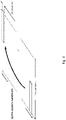
- Figure 7 shows an example of PMI reporting with i 1,1 as the slow varying PMI and i 1,2 as the fast varying PMI.
- the grouping of specific (O 1 , O 2 ) pair values into combination 1 and combination 2 in Table 13 is done such that the dimension with a higher angular spread (i.e., the dimension corresponding to the more frequently varying PMI) has the same or higher oversampling factor when compared to the the dimension with the lower angular spread (i.e., the dimension corresponding to the slowly varying PMI).
- the dimension corresponding to the slowly varying PMI is the vertical dimension and the dimension corresponding to the more frequently varying PMI is the horizontal dimension.
- identification of which index among the two first PMI indices i 1,1 and i 1,2 corresponds to the slowly varying PMI is identified via RRC signaling.
- the eNodeB semi-statically configures the UE with a binary RRC parameter.
- the binary parameter takes on one value (say 'zero')
- i 1,1 is identified as the slowly varying PMI
- i 1,2 is identified as the more frequently varying PMI.
- the binary parameter takes on the second value (say 'one')
- i 1,2 is identified as the slowly varying PMI and i 1,1 is identified as the more frequently varying PMI.
- the orthogonal beam group parameter k is only relevant to the class A codebooks corresponding to ranks 3-4 (i.e., there is no k parameter for Class A codebooks of ranks 1, 2, 5-8). Hence, it is desirable to feedback the k parameter to the eNodeB after the UE has reported the rank indication (RI).
- the slowly varying PMI as identified by one of the variants or approaches described herein is jointly encoded with the RI and reported in one subframe as part of the periodic CSI on PUCCH. This jointly encoded report has a feedback periodicity of T1.
- the UE determines the rank (i.e., RI) to be either 3 or 4, then the more frequently varying PMI as identified by one of the variants in described herein jointly encoded with the orthogonal beam group parameter k and reported in a different subframe as part of the periodic CSI on PUCCH with a feedback periodicity of T2.
- the UE determines the rank (i.e., RI) to be one among 1, 2, 5, 6, 7, 8, then k is not present in the corresponding codebooks, the more frequently varying PMI as identified by one of the variants or approaches described herein is reported as part of the periodic CSI on PUCCH with a feedback periodicity of T2.
- the feedback periodicity T1 is larger than the feedback periodicity T2.
- Figure 8 shows an example of encoding the slow varying PMI with RI and fast varying PMI with parameter k when the reported rank is either 3 or 4.
- Terminal 10 schematically shows a terminal 10, which may be implemented in this example as a user equipment.
- Terminal 10 comprises control circuitry 20, which may comprise a controller connected to a memory.
- a receiving module and/or transmitting module and/or control or processing module and/or CIS receiving module and/or scheduling module, may be implemented in and/or executable by, the control circuitry 20, in particular as module in the controller.
- Terminal 10 also comprises radio circuitry 22 providing receiving and transmitting or transceiving functionality, the radio circuitry 22 connected or connectable to the control circuitry.
- An antenna circuitry 24 of the terminal 10 is connected or connectable to the radio circuitry 22 to collect or send and/or amplify signals.
- Radio circuitry 22 and the control circuitry 20 controlling it are configured for cellular communication with a network on a first cell /carrier and a second cell /carrier, in particular utilizing E-UTRAN/LTE resources as described herein.
- the terminal 10 may be adapted to carry out any of the methods for operating a terminal disclosed herein; in particular, it may comprise corresponding circuitry, e.g. control circuitry.
- the terminal may comprise dual radio circuitry (for independent TX/RX operation).
- FIG 10 schematically show a network node or base station 100, which in particular may be an eNodeB, for example a MeNB or SeNB.
- Network node 100 comprises control circuitry 120, which may comprise a controller connected to a memory.
- a receiving module and/or transmitting module and/or control or processing module and/or scheduling module and/or CIS receiving module, may be implemented in and/or executable by the control circuitry 120.
- the control circuitry is connected to control radio circuitry 122 of the network node 100, which provides receiver and transmitter and/or transceiver functionality.
- An antenna circuitry 124 may be connected or connectable to radio circuitry 122 for signal reception or transmittance and/or amplification.
- the network node 100 may be adapted to carry out any of the methods for operating a network node disclosed herein; in particular, it may comprise corresponding circuitry, e.g. control circuitry.
- Figure 11 shows a flow diagram representing an exemplary algorithm, respectively a method, for operating a terminal, which may be any terminal discussed herein.
- the method comprises an action TS10 of performing reporting based on a configuration, the configuration indicating the timing of reporting of first angular transmission information and/or indicating the timing of reporting of second angular transmission information.
- the method may comprise an action TS08 of receiving the configuration.
- Action TS10 may be performed based on, and/or after, action TS08.
- Figure 12 shows an exemplary terminal, which may be any terminal disclosed herein.
- the terminal comprises a reporting module TM10 for performing action TS10.
- the terminal may optionally comprise a receiving module TM08 for performing action TS08.
- Figure 13 shows a flow diagram representing an exemplary algorithm, respectively a method, for operating a network node, which may be any network node discussed herein.
- the method comprises an action NS10 of configuring a terminal for performing reporting, wherein configuring comprises indicating different timings for reporting of first angular transmission information and second angular transmission information.
- the method may comprise an action NS08 of determining different timings (e.g., a first and a second timing) for reporting of first angular transmission information and/or second angular transmission information.
- Figure 14 shows an exemplary network node, which may be any network node disclosed herein.
- the network node comprises a configuring module NM10 for performing action NS10. It may optionally comprise a determining module NM08 for performing action NS08.
- the solutions and approaches presented in this disclosure generally provide efficient mechanisms for identifying the dimension corresponding to the slowly varying PMI and the dimension corresponding to the more frequently varying PMI at the UE.
- the solutions for dimension identification in this disclosure are configurable with regards to the RRC parameters N 1 , N 2 , O 1 and O 2 which are used to configure the Release 13 class A codebook.
- the disclosure provides an efficient approach to report the beam group parameter k .
- network node adapted for performing any one of the methods for operating a network node described herein.
- terminal or UE adapted for performing any one of the methods for operating a terminal described herein.
- There may be considered a wireless communication system comprising a terminal and a network node as disclosed herein.
- control circuitry comprising code executable by control circuitry, the code causing the control circuitry to carry out and/or control any one of the method for operating a terminal or user equipment or network node as described herein, in particular if executed on control circuitry, which may be control circuitry of a radio node like a user equipment or a network node as described herein.
- a carrier medium arrangement carrying and/or storing at least any one of the program products described herein and/or code executable by control circuitry, the code causing the control circuitry to perform and/or control at least any one of the methods described herein.
- a carrier medium arrangement may comprise one or more carrier media.
- a carrier medium may be accessible and/or readable and/or receivable by control circuitry. Storing data and/or a program product and/or code may be seen as part of carrying data and/or a program product and/or code.
- a carrier medium generally may comprise a guiding/transporting medium and/or a storage medium.
- a guiding/transporting medium may be adapted to carry and/or carry and/or store signals, in particular electromagnetic signals and/or electrical signals and/or magnetic signals and/or optical signals.
- a carrier medium, in particular a guiding/transporting medium may be adapted to guide such signals to carry them.
- a carrier medium, in particular a guiding/transporting medium may comprise the electromagnetic field, e.g. radio waves or microwaves, and/or optically transmissive material, e.g. glass fiber, and/or cable.
- a storage medium may comprise at least one memory, in particular at least one of volatile or non-volatile memory, a buffer, a cache, an optical disc, magnetic memory, flash memory, etc.
- Code may comprise instructions executable by control circuitry and/or parameters, which may be associated to instructions.
- wireless communication may be communication, in particular transmission and/or reception of data, via electromagnetic waves and/or an air interface, in particular radio waves, e.g. in a wireless communication network and/or utilizing a radio access technology (RAT).
- the communication may involve one or more than one terminal connected to a wireless communication network and/or more than one node of a wireless communication network and/or in a wireless communication network. It may be envisioned that a node in or for communication, and/or in, of or for a wireless communication network is adapted for communication utilizing one or more RATs, in particular LTE/E-UTRA.
- a communication may generally involve transmitting and/or receiving messages, in particular in the form of packet data.
- a message or packet may comprise control and/or configuration data and/or payload data and/or represent and/or comprise a batch of physical layer transmissions.
- Control and/or configuration data may refer to data pertaining to the process of communication and/or nodes and/or terminals of the communication. It may, e.g., include header information or a header and/or address data referring to a node or terminal of the communication and/or data pertaining to the transmission mode and/or spectral configuration and/or frequency and/or coding and/or timing and/or bandwidth as data pertaining to the process of communication or transmission, e.g. in a header.
- Each node or terminal involved in communication may comprise radio circuitry and/or control circuitry and/or antenna circuitry, which may be arranged to utilize and/or implement one or more than one radio access technologies.
- Radio circuitry of a node or terminal may generally be adapted for the transmission and/or reception of radio waves, and in particular may comprise a corresponding transmitter and/or receiver and/or transceiver, which may be connected or connectable to antenna circuitry and/or control circuitry.
- Control circuitry of a node or terminal may comprise a controller and/or memory arranged to be accessible for the controller for read and/or write access. The controller may be arranged to control the communication and/or the radio circuitry and/or provide additional services.
- Circuitry of a node or terminal, in particular control circuitry, e.g. a controller may be programmed to provide the functionality described herein.
- a corresponding program code may be stored in an associated memory and/or storage medium and/or be hardwired and/or provided as firmware and/or software and/or in hardware.
- a controller may generally comprise a processor and/or microprocessor and/or microcontroller and/or FPGA (Field-Programmable Gate Array) device and/or ASIC (Application Specific Integrated Circuit) device. More specifically, it may be considered that control circuitry comprises and/or may be connected or connectable to memory, which may be adapted to be accessible for reading and/or writing by the controller and/or control circuitry.
- Radio access technology may generally comprise, e.g., Bluetooth and/or Wifi and/or WIMAX and/or cdma2000 and/or GERAN and/or UTRAN and/or in particular E-Utran and/or LTE.
- a communication may in particular comprise a physical layer (PHY) transmission and/or reception, onto which logical channels and/or logical transmission and/or receptions may be imprinted or layered.
- PHY physical layer
- a wireless communication network or cellular network may comprise a network node, in particular a radio network node, which may be connected or connectable to a core network, e.g. a core network with an evolved network core, e.g. according to LTE.
- a network node may e.g. be a base station.
- the connection between the network node and the core network/network core may be at least partly based on a cable/landline connection. Operation and/or communication and/or exchange of signals involving part of the core network, in particular layers above a base station or eNB, and/or via a predefined cell structure provided by a base station or eNB, may be considered to be of cellular nature or be called cellular operation.
- a terminal may be implemented as a user equipment; it may generally be considered that a terminal is adapted to provide and/or define an end point of a wireless communication and/or for a wireless communication network.
- a terminal or a user equipment may generally be a device configured for wireless device-to-device communication and/or a terminal for a wireless and/or cellular network, in particular a mobile terminal, for example a mobile phone, smart phone, tablet, PDA, etc.
- a user equipment or terminal may be a node of or for a wireless communication network as described herein, e.g. if it takes over some control and/or relay functionality for another terminal or node. It may be envisioned that terminal or user equipment is adapted for one or more RATs, in particular LTE/E-UTRA.
- a terminal or user equipment comprises radio circuitry and/control circuitry for wireless communication.
- Radio circuitry may comprise for example a receiver device and/or transmitter device and/or transceiver device.
- Control circuitry may include a controller, which may comprise a microprocessor and/or microcontroller and/or FPGA (Field-Programmable Gate Array) device and/or ASIC (Application Specific Integrated Circuit) device. It may be considered that control circuitry comprises or may be connected or connectable to memory, which may be adapted to be accessible for reading and/or writing by the controller and/or control circuitry. It may be considered that a terminal or user equipment is configured to be a terminal or user equipment adapted for LTE/E-UTRAN.
- a terminal may be adapted to support dual connectivity. It may comprise two independently operable transmitter (or transceiver) circuitries and/or two independently operable receiver circuitries; for dual connectivity, it may be adapted to utilize one transmitter (and/or receiver or transceiver, if provided) for communication with a master network node and one transmitter (and/or receiver or transceiver, if provided) for communication with a secondary network node. It may be considered that a terminal comprises more than two such independently operable circuitries.
- a network node or base station may be any kind of base station of a wireless and/or cellular network adapted to serve one or more terminals or user equipments. It may be considered that a base station is a node or network node of a wireless communication network.
- a network node or base station may be adapted to provide and/or define and/or to serve one or more cells of the network and/or to allocate frequency and/or time resources for communication to one or more nodes or terminals of a network.
- any node adapted to provide such functionality may be considered a base station.
- a base station or more generally a network node comprises radio circuitry and/or control circuitry for wireless communication. It may be envisioned that a base station or network node is adapted for one or more RATs, in particular LTE/E-UTRA .
- Radio circuitry may comprise for example a receiver device and/or transmitter device and/or transceiver device.
- Control circuitry may include a controller, which may comprise a microprocessor and/or microcontroller and/or FPGA (Field-Programmable Gate Array) device and/or ASIC (Application Specific Integrated Circuit) device.
- control circuitry comprises or may be connected or connectable to memory, which may be adapted to be accessible for reading and/or writing by the controller and/or control circuitry.
- a base station may be arranged to be a node of a wireless communication network, in particular configured for and/or to enable and/or to facilitate and/or to participate in cellular communication, e.g. as a device directly involved or as an auxiliary and/or coordinating node.
- a base station may be arranged to communicate with a core network and/or to provide services and/or control to one or more user equipments and/or to relay and/or transport communications and/or data between one or more user equipments and a core network and/or another base station.
- a network node or base station may generally be adapted to allocate and/or schedule time/frequency resources of a network and/or one or more cells serviced by the base station.
- An eNodeB eNB
- eNB eNodeB
- a base station is configured as or connected or connectable to an Evolved Packet Core (EPC) and/or to provide and/or connect to corresponding functionality.
- EPC Evolved Packet Core
- the functionality and/or multiple different functions of a base station may be distributed over one or more different devices and/or physical locations and/or nodes.
- a base station may be considered to be a node of a wireless communication network.
- a base station may be considered to be configured to be a controlling node and/or coordinating node and/or to allocate resources in particular for cellular communication via one or more than one cell.
- At least one uplink (UL) connection and/or channel and/or carrier and at least one downlink (DL) connection and/or channel and/or carrier e.g. via and/or defining a cell, which may be provided by a network node, in particular a base station or eNodeB .
- An uplink direction may refer to a data transfer direction from a terminal to a network node, e.g. base station and/or relay station.
- a downlink direction may refer to a data transfer direction from a network node, e.g. base station and/or relay node, to a terminal.
- UL and DL may be associated to different frequency resources, e.g. carriers and/or spectral bands.
- a cell may comprise at least one uplink carrier and at least one downlink carrier, which may have different frequency bands.
- a network node e.g. a base station or eNodeB, may be adapted to provide and/or define and/or control one or more cells, e.g. a group of cells, which may be carrier aggregated (CA) cells.
- the group of cells may comprise at least one primary cell, which may be considered to be a member of the group and/or to be associated to the group.
- the cell group may comprise one or more secondary cells (it should be noted that every group may comprise secondary cells, not only a secondary group; the secondary in this context refers to being secondary to the primary cell of a group).
- a primary cell may be adapted and/or utilised for providing control information (in particular allocation data, and/or scheduling and/or allocation information regarding the primary cell and/or the group of cells to and/or from a terminal connected for communication (transmission and reception) and/or configured with the cell.
- the control information may pertain to the primary cell and/or the group of cells.
- Each primary cell and/or the associated group may be associated to a specific network node.
- a master network node may be adapted to provide and/or service and/or define a primary cell in a master cell group.
- a secondary network node may be adapted to provide and/or service and/or define a secondary cell group.
- Resources or communication resources may generally be frequency and/or time resources, which may comprises e.g. frames, subframes, slots, resource blocks, carriers, subcarriers, channels, frequency/spectral bands, etc.
- Allocated or scheduled resources may comprise and/or refer to frequency-related information, in particular regarding one or more carriers and/or bandwidth and/or subcarriers and/or time-related information, in particular regarding frames and/or slots and/or subframes, and/or regarding resource blocks and/or time/frequency hopping information.
- Transmitting on allocated resources and/or utilizing allocated resources may comprise transmitting data on the resources allocated, e.g. on the frequency and/or subcarrier and/or carrier and/or timeslots or subframes indicated.
- a network or a node of a network e.g. a network node or allocation node, e.g. a base station, may be adapted to determine and/or transmit corresponding allocation or scheduling data, e.g. data indicating release or de-allocation of resources and/or scheduling of UL and/or DL resources.
- resource allocation may be performed by the network and/or by a network node; a network node adapted for providing resource allocation/scheduling for one or more than one terminals may be considered to be a controlling node.
- Resources may be allocated and/or scheduled on a cell level and/or by a network node servicing and/or providing the cell.
- Allocation data may be considered to be data indicating and/or granting resources allocated by a network node, e.g. a controlling and/or allocation node, in particular data identifying or indicating which resources are reserved or allocated, e.g. for cellular communication, which may generally comprise transmitting and/or receiving data and/or signals; the allocation data may indicate a resource grant or release and/or resource scheduling.
- a grant or resource grant may be considered to be one example of allocation data. It may be considered that an allocation node is adapted to transmit allocation data directly to a node and/or indirectly, e.g. via a relay node and/or another node or base station.
- Allocation data may comprise control data and/or be part of or form a message, in particular according to a pre-defined format, for example a DCI format, which may be defined in a standard, e.g. LTE.
- allocation data may comprise information and/or instructions to reserve resources or to release resources, which may already be allocated.
- a terminal may generally be adapted to perform transmission of data to, e.g. UL data, and/or reception of data from, a network node and/or to more than one network nodes, according to allocation data.
- Allocation data may be seen as an example of configuration data.
- Configuration data generally may comprise allocation data and/or control information or instruction, e.g.
- TPC and/or information indicating feedback in particular measurement feedback and/or a PMI configuration or setup.
- a PMI configuration or setup may indicate PMI/s for different dimensions to be sent at different times and/or time-intervals and/or with different periodicity.
- Different dimensions for PMI may indicated orthogonal arrangements, in particular vertical and horizontal. The dimensions may refer to angular beamforming profiles and/or to beamforming arrangements or procedures, in particular to precoders for different dimensions.
- LTE Long Term Evolution
- LTE-A LTE-Advanced
- GSM Global System for Mobile Communications
- TSs Technical Specifications
- 3GPP Third Generation Partnership Project
- PM Performance Management
- a device that is adapted or configured for specific functionality may comprise the hardware (e.g. circuitry) and/or software and/or firmware allowing it to provide the functionality or perform accordingly.
- Configuring a device may comprise setting operational parameters of the device; configuring for specific functionality and/or for or with a specific configuration may comprise setting such parameters to enable the device to provide the functionality and/or to operate according to the configuration.
- Operational parameters may comprise any parameter influencing the operation of the device, in particular pertaining to radio circuitry and/or reception or transmission characteristics.
- a device may configure itself and/or be configured by another device, e.g. by receiving corresponding configuration data from that device.
- Configuring may comprise transmitting (by the configuring device) or receiving (by the configured device) configuration data on any or any combination of protocol levels, e.g. on a physical or radio level and/or higher levels, e.g. RRC level (Radio Resource Control).
- protocol levels e.g. on a physical or radio level and/or higher levels, e.g. R
- Configuration data for configuring a device for an adapted guarding time interval may comprise information indicating the type of symbol the adapted guarding time interval pertains to (e.g., UL/DL or transmission/receiving), and/or the (adapted) length of the guard interval and/or the core symbol, and/or the location of the guard interval associated in the symbol, in particular relating to the core symbol (e.g. prefix or suffix), and/or a duration for which the adapted guarding time length is valid (e.g., in terms of frames).
- Configuring a terminal or UE, by a network or network node may comprise transmitting, by the network or network node, one or more parameters and/or commands to the terminal or UE, and/or the terminal or UE changing it configuration and/or setup based on received parameters and/or commands from the network and/or the network node.
- a terminal may generally be a UE (User Equipment), in particular for LTE or later standards; the terms may be interchangeably used. It is noted that a terminal or UE may comprise and/or pertain to devices used or adapted for MTC (machine-type communication) or M2M (machine-to-machine communication), which do not require a person as user; such devices still may be seen as users of the network or RAT (Radio Access Technology).
- MTC machine-type communication
- M2M machine-to-machine communication
- a terminal being configured with a cell and/or carrier, and/or being connected to a network node via a cell, may be in a state in which it may communicate (transmit and/or receive data, e.g. with the network node) using the cell or carrier, e.g. being registered with the network for communication and/or being synchronized to the cell and/or carrier; in particular, the cell may be activated for the terminal.
Landscapes
- Engineering & Computer Science (AREA)
- Computer Networks & Wireless Communication (AREA)
- Signal Processing (AREA)
- Physics & Mathematics (AREA)
- Electromagnetism (AREA)
- Mathematical Physics (AREA)
- Mobile Radio Communication Systems (AREA)
Claims (6)
- Procédé pour faire fonctionner un terminal (10) dans un réseau de communication sans fil, le procédé comprenant :la mise en œuvre d'un rapport sur la base d'une configuration, la configuration indiquant une première temporisation de rapport de premières informations de transmission angulaire et une deuxième temporisation de rapport de deuxièmes informations de transmission angulaire,dans lequel la première temporisation est différente de la deuxième temporisation,dans lequel les premières informations de transmission angulaire se rapportent à des deuxièmes informations de transmission angulaire variant plus vite que les deuxièmes informations de transmission angulaire,dans lequel le rapport des premières informations de transmission angulaire est mis en œuvre plus souvent et/ou plus vite que le rapport des deuxièmes informations de transmission angulaire, etdans lequel les premières informations de transmission angulaire comprennent un indicateur de groupe de faisceaux encodé conjointement avec un indicateur de matrice de précodage.
- Terminal (10) pour un réseau de communication sans fil, le terminal (10) étant conçu pour mettre en œuvre un rapport sur la base d'une configuration, la configuration indiquant une première temporisation de rapport de premières informations de transmission angulaire et indiquant une deuxième temporisation de rapport de deuxièmes informations de transmission angulaire, dans lequel la première temporisation est différente de la deuxième temporisation,dans lequel les premières informations de transmission angulaire se rapportent à des deuxièmes informations de transmission angulaire variant plus vite que les deuxièmes informations de transmission angulaire,dans lequel le rapport des premières informations de transmission angulaire est mis en œuvre plus souvent et/ou plus vite que le rapport des deuxièmes informations de transmission angulaire, etdans lequel les premières informations de transmission angulaire comprennent un indicateur de groupe de faisceaux encodé conjointement avec un indicateur de matrice de précodage.
- Procédé pour faire fonctionner un nœud de réseau (100) dans un réseau de communication sans fil, le procédé comprenant la configuration d'un terminal (10) pour mettre en œuvre un rapport sur la base d'une configuration, la configuration indiquant une première temporisation de rapport de premières informations de transmission angulaire et une deuxième temporisation de rapport de deuxièmes informations de transmission angulaire,dans lequel la première temporisation est différente de la deuxième temporisation,dans lequel les premières informations de transmission angulaire se rapportent à des deuxièmes informations de transmission angulaire variant plus vite que les deuxièmes informations de transmission angulaire,dans lequel le rapport des premières informations de transmission angulaire est mis en œuvre plus souvent et/ou plus vite que le rapport des deuxièmes informations de transmission angulaire, etdans lequel les premières informations de transmission angulaire comprennent un indicateur de groupe de faisceaux encodé conjointement avec un indicateur de matrice de précodage.
- Nœud de réseau (100) pour un réseau de communication sans fil, le nœud de réseau (100) étant conçu pour configurer un terminal (10) pour mettre en œuvre un rapport sur la base d'une configuration, la configuration indiquant une première temporisation de rapport de premières informations de transmission angulaire et une deuxième temporisation de rapport de deuxièmes informations de transmission angulaire,dans lequel la première temporisation est différente de la deuxième temporisation,dans lequel les premières informations de transmission angulaire se rapportent à des deuxièmes informations de transmission angulaire variant plus vite que les deuxièmes informations de transmission angulaire,dans lequel le rapport des premières informations de transmission angulaire est mis en œuvre plus souvent et/ou plus vite que le rapport des deuxièmes informations de transmission angulaire, etdans lequel les premières informations de transmission angulaire comprennent un indicateur de groupe de faisceaux encodé conjointement avec un indicateur de matrice de précodage.
- Programme informatique comprenant des instructions qui, lorsque le programme est exécuté par un ordinateur, amènent l'ordinateur à effectuer le procédé selon l'une des revendications 1 et 3.
- Support de données lisible par ordinateur sur lequel est stocké le programme informatique selon la revendication 5.
Applications Claiming Priority (2)
| Application Number | Priority Date | Filing Date | Title |
|---|---|---|---|
| US201562255728P | 2015-11-16 | 2015-11-16 | |
| PCT/SE2016/051126 WO2017086864A1 (fr) | 2015-11-16 | 2016-11-16 | Création de rapport dans différentes dimensions |
Publications (2)
| Publication Number | Publication Date |
|---|---|
| EP3378169A1 EP3378169A1 (fr) | 2018-09-26 |
| EP3378169B1 true EP3378169B1 (fr) | 2023-01-04 |
Family
ID=57442771
Family Applications (1)
| Application Number | Title | Priority Date | Filing Date |
|---|---|---|---|
| EP16804924.5A Active EP3378169B1 (fr) | 2015-11-16 | 2016-11-16 | Création de rapport dans différentes dimensions |
Country Status (3)
| Country | Link |
|---|---|
| US (1) | US10389422B2 (fr) |
| EP (1) | EP3378169B1 (fr) |
| WO (1) | WO2017086864A1 (fr) |
Families Citing this family (11)
| Publication number | Priority date | Publication date | Assignee | Title |
|---|---|---|---|---|
| EP2484074B1 (fr) * | 2009-09-30 | 2014-06-25 | Telefonaktiebolaget L M Ericsson (PUBL) | Reconfiguration de porteuses de composant actives dans des systèmes sans fil à porteuses multiples |
| US10693522B1 (en) * | 2015-09-04 | 2020-06-23 | Lg Electronics Inc. | Method and device for performing PUCCH feedback on basis of beamformed CSI RS resource in wireless communication system |
| CN109041098A (zh) * | 2017-06-12 | 2018-12-18 | 维沃移动通信有限公司 | 一种终端测量配置方法、终端及基站 |
| CN109392072B (zh) * | 2017-08-14 | 2021-08-03 | 普天信息技术有限公司 | 功率余量的计算方法 |
| CN111357371B (zh) * | 2017-11-17 | 2024-01-26 | 中兴通讯股份有限公司 | 用于多载波系统中的上行链路传输的方法和装置 |
| WO2020006755A1 (fr) * | 2018-07-06 | 2020-01-09 | Nec Corporation | Livre de codes multi-trp |
| US11201706B2 (en) * | 2018-10-22 | 2021-12-14 | Qualcomm Incorporated | Soft ACK-NACK with CSI codebook |
| CN111182619B (zh) * | 2018-11-12 | 2022-04-15 | 大唐移动通信设备有限公司 | 一种上行功率控制的方法和设备 |
| US11569886B2 (en) * | 2019-04-01 | 2023-01-31 | Qualcomm Incorporated | Network-sensitive transmit diversity scheme |
| US20220200667A1 (en) * | 2019-05-07 | 2022-06-23 | Nokia Technologies Oy | Apparatus, method and computer program |
| US11664871B2 (en) * | 2019-06-10 | 2023-05-30 | Qualcomm Incorporated | Methods and apparatus for UE initiated beam reporting |
Family Cites Families (5)
| Publication number | Priority date | Publication date | Assignee | Title |
|---|---|---|---|---|
| US9178583B2 (en) | 2013-01-08 | 2015-11-03 | Samsung Electronics Co., Ltd. | Channel state information feedback design in advanced wireless communication systems |
| US9866303B2 (en) | 2013-03-11 | 2018-01-09 | Lg Electronics Inc. | Method and device for reporting channel state information in wireless communication system |
| WO2015027118A1 (fr) * | 2013-08-22 | 2015-02-26 | Qualcomm Incorporated | Utilisation d'un signal de référence pour une localisation en intérieur |
| WO2015060680A2 (fr) * | 2013-10-24 | 2015-04-30 | 엘지전자 주식회사 | Procédé pour rapporter des informations d'état de canal dans un système de communication sans fil, et appareil correspondant |
| US10389509B2 (en) * | 2015-07-30 | 2019-08-20 | Futurewei Technologies, Inc. | Multi-user, full duplex in-band communication in wireless networks |
-
2016
- 2016-11-16 EP EP16804924.5A patent/EP3378169B1/fr active Active
- 2016-11-16 US US15/776,435 patent/US10389422B2/en not_active Expired - Fee Related
- 2016-11-16 WO PCT/SE2016/051126 patent/WO2017086864A1/fr active Application Filing
Also Published As
| Publication number | Publication date |
|---|---|
| US10389422B2 (en) | 2019-08-20 |
| WO2017086864A1 (fr) | 2017-05-26 |
| US20180343045A1 (en) | 2018-11-29 |
| EP3378169A1 (fr) | 2018-09-26 |
Similar Documents
| Publication | Publication Date | Title |
|---|---|---|
| EP3378169B1 (fr) | Création de rapport dans différentes dimensions | |
| US11388685B2 (en) | Configurable codebook for advanced CSI feedback overhead reduction | |
| US11804885B2 (en) | Codebook subset restriction for full-dimension MIMO | |
| EP3602933B1 (fr) | Rétroaction de csi semi-persistantes sur pusch | |
| US20220360415A1 (en) | System and Method for Flexible Channel State Information-Reference Signal Transmission | |
| US11538568B2 (en) | Methods and systems for CSI-RS port selection for CSI-reporting | |
| EP2918095B1 (fr) | Procédé de rétroaction d'informations d'état de canal dans un système de communication sans fil et appareil associé | |
| EP2621103B1 (fr) | Procédé et appareil assurant une rétroaction efficace dans un système de communication sans fil qui accepte plusieurs antennes | |
| US20180083681A1 (en) | A CSI Report Framework for Enhanced Separate Dimension Feedback | |
| US11245449B2 (en) | Network node, wireless device and methods thereby to indicate a first set of antenna ports and a second set of antenna ports | |
| US9413442B2 (en) | Method and apparatus for reporting channel state information in a wireless communication system | |
| EP3465968B1 (fr) | Procédés et équipement utilisateur de gestion de communication | |
| KR101706967B1 (ko) | 무선 통신 시스템에서 랭크 인덱스의 비트 길이를 결정하는 방법 및 장치 | |
| WO2013157899A1 (fr) | Procédé de notification d'état de voie, et appareil correspondant | |
| EP3577836B1 (fr) | Indication dynamique pour rétroaction d'informations d'état de canal | |
| US20180041973A1 (en) | Estimating Joint CSI based on Multiple CSI Reports |
Legal Events
| Date | Code | Title | Description |
|---|---|---|---|
| STAA | Information on the status of an ep patent application or granted ep patent |
Free format text: STATUS: UNKNOWN |
|
| STAA | Information on the status of an ep patent application or granted ep patent |
Free format text: STATUS: THE INTERNATIONAL PUBLICATION HAS BEEN MADE |
|
| PUAI | Public reference made under article 153(3) epc to a published international application that has entered the european phase |
Free format text: ORIGINAL CODE: 0009012 |
|
| STAA | Information on the status of an ep patent application or granted ep patent |
Free format text: STATUS: REQUEST FOR EXAMINATION WAS MADE |
|
| 17P | Request for examination filed |
Effective date: 20180515 |
|
| AK | Designated contracting states |
Kind code of ref document: A1 Designated state(s): AL AT BE BG CH CY CZ DE DK EE ES FI FR GB GR HR HU IE IS IT LI LT LU LV MC MK MT NL NO PL PT RO RS SE SI SK SM TR |
|
| AX | Request for extension of the european patent |
Extension state: BA ME |
|
| RAP1 | Party data changed (applicant data changed or rights of an application transferred) |
Owner name: TELEFONAKTIEBOLAGET LM ERICSSON (PUBL) |
|
| DAV | Request for validation of the european patent (deleted) | ||
| DAX | Request for extension of the european patent (deleted) | ||
| STAA | Information on the status of an ep patent application or granted ep patent |
Free format text: STATUS: EXAMINATION IS IN PROGRESS |
|
| 17Q | First examination report despatched |
Effective date: 20190531 |
|
| STAA | Information on the status of an ep patent application or granted ep patent |
Free format text: STATUS: EXAMINATION IS IN PROGRESS |
|
| GRAP | Despatch of communication of intention to grant a patent |
Free format text: ORIGINAL CODE: EPIDOSNIGR1 |
|
| STAA | Information on the status of an ep patent application or granted ep patent |
Free format text: STATUS: GRANT OF PATENT IS INTENDED |
|
| GRAS | Grant fee paid |
Free format text: ORIGINAL CODE: EPIDOSNIGR3 |
|
| INTG | Intention to grant announced |
Effective date: 20220930 |
|
| GRAA | (expected) grant |
Free format text: ORIGINAL CODE: 0009210 |
|
| STAA | Information on the status of an ep patent application or granted ep patent |
Free format text: STATUS: THE PATENT HAS BEEN GRANTED |
|
| AK | Designated contracting states |
Kind code of ref document: B1 Designated state(s): AL AT BE BG CH CY CZ DE DK EE ES FI FR GB GR HR HU IE IS IT LI LT LU LV MC MK MT NL NO PL PT RO RS SE SI SK SM TR |
|
| REG | Reference to a national code |
Ref country code: GB Ref legal event code: FG4D |
|
| REG | Reference to a national code |
Ref country code: DE Ref legal event code: R096 Ref document number: 602016077288 Country of ref document: DE |
|
| REG | Reference to a national code |
Ref country code: CH Ref legal event code: EP |
|
| REG | Reference to a national code |
Ref country code: AT Ref legal event code: REF Ref document number: 1542668 Country of ref document: AT Kind code of ref document: T Effective date: 20230115 |
|
| REG | Reference to a national code |
Ref country code: IE Ref legal event code: FG4D |
|
| REG | Reference to a national code |
Ref country code: NL Ref legal event code: FP |
|
| REG | Reference to a national code |
Ref country code: LT Ref legal event code: MG9D |
|
| REG | Reference to a national code |
Ref country code: AT Ref legal event code: MK05 Ref document number: 1542668 Country of ref document: AT Kind code of ref document: T Effective date: 20230104 |
|
| PG25 | Lapsed in a contracting state [announced via postgrant information from national office to epo] |
Ref country code: RS Free format text: LAPSE BECAUSE OF FAILURE TO SUBMIT A TRANSLATION OF THE DESCRIPTION OR TO PAY THE FEE WITHIN THE PRESCRIBED TIME-LIMIT Effective date: 20230104 Ref country code: PT Free format text: LAPSE BECAUSE OF FAILURE TO SUBMIT A TRANSLATION OF THE DESCRIPTION OR TO PAY THE FEE WITHIN THE PRESCRIBED TIME-LIMIT Effective date: 20230504 Ref country code: NO Free format text: LAPSE BECAUSE OF FAILURE TO SUBMIT A TRANSLATION OF THE DESCRIPTION OR TO PAY THE FEE WITHIN THE PRESCRIBED TIME-LIMIT Effective date: 20230404 Ref country code: LV Free format text: LAPSE BECAUSE OF FAILURE TO SUBMIT A TRANSLATION OF THE DESCRIPTION OR TO PAY THE FEE WITHIN THE PRESCRIBED TIME-LIMIT Effective date: 20230104 Ref country code: LT Free format text: LAPSE BECAUSE OF FAILURE TO SUBMIT A TRANSLATION OF THE DESCRIPTION OR TO PAY THE FEE WITHIN THE PRESCRIBED TIME-LIMIT Effective date: 20230104 Ref country code: HR Free format text: LAPSE BECAUSE OF FAILURE TO SUBMIT A TRANSLATION OF THE DESCRIPTION OR TO PAY THE FEE WITHIN THE PRESCRIBED TIME-LIMIT Effective date: 20230104 Ref country code: ES Free format text: LAPSE BECAUSE OF FAILURE TO SUBMIT A TRANSLATION OF THE DESCRIPTION OR TO PAY THE FEE WITHIN THE PRESCRIBED TIME-LIMIT Effective date: 20230104 Ref country code: AT Free format text: LAPSE BECAUSE OF FAILURE TO SUBMIT A TRANSLATION OF THE DESCRIPTION OR TO PAY THE FEE WITHIN THE PRESCRIBED TIME-LIMIT Effective date: 20230104 |
|
| PG25 | Lapsed in a contracting state [announced via postgrant information from national office to epo] |
Ref country code: SE Free format text: LAPSE BECAUSE OF FAILURE TO SUBMIT A TRANSLATION OF THE DESCRIPTION OR TO PAY THE FEE WITHIN THE PRESCRIBED TIME-LIMIT Effective date: 20230104 Ref country code: PL Free format text: LAPSE BECAUSE OF FAILURE TO SUBMIT A TRANSLATION OF THE DESCRIPTION OR TO PAY THE FEE WITHIN THE PRESCRIBED TIME-LIMIT Effective date: 20230104 Ref country code: IS Free format text: LAPSE BECAUSE OF FAILURE TO SUBMIT A TRANSLATION OF THE DESCRIPTION OR TO PAY THE FEE WITHIN THE PRESCRIBED TIME-LIMIT Effective date: 20230504 Ref country code: GR Free format text: LAPSE BECAUSE OF FAILURE TO SUBMIT A TRANSLATION OF THE DESCRIPTION OR TO PAY THE FEE WITHIN THE PRESCRIBED TIME-LIMIT Effective date: 20230405 Ref country code: FI Free format text: LAPSE BECAUSE OF FAILURE TO SUBMIT A TRANSLATION OF THE DESCRIPTION OR TO PAY THE FEE WITHIN THE PRESCRIBED TIME-LIMIT Effective date: 20230104 |
|
| REG | Reference to a national code |
Ref country code: DE Ref legal event code: R097 Ref document number: 602016077288 Country of ref document: DE |
|
| PG25 | Lapsed in a contracting state [announced via postgrant information from national office to epo] |
Ref country code: SM Free format text: LAPSE BECAUSE OF FAILURE TO SUBMIT A TRANSLATION OF THE DESCRIPTION OR TO PAY THE FEE WITHIN THE PRESCRIBED TIME-LIMIT Effective date: 20230104 Ref country code: RO Free format text: LAPSE BECAUSE OF FAILURE TO SUBMIT A TRANSLATION OF THE DESCRIPTION OR TO PAY THE FEE WITHIN THE PRESCRIBED TIME-LIMIT Effective date: 20230104 Ref country code: EE Free format text: LAPSE BECAUSE OF FAILURE TO SUBMIT A TRANSLATION OF THE DESCRIPTION OR TO PAY THE FEE WITHIN THE PRESCRIBED TIME-LIMIT Effective date: 20230104 Ref country code: DK Free format text: LAPSE BECAUSE OF FAILURE TO SUBMIT A TRANSLATION OF THE DESCRIPTION OR TO PAY THE FEE WITHIN THE PRESCRIBED TIME-LIMIT Effective date: 20230104 Ref country code: CZ Free format text: LAPSE BECAUSE OF FAILURE TO SUBMIT A TRANSLATION OF THE DESCRIPTION OR TO PAY THE FEE WITHIN THE PRESCRIBED TIME-LIMIT Effective date: 20230104 |
|
| PLBE | No opposition filed within time limit |
Free format text: ORIGINAL CODE: 0009261 |
|
| STAA | Information on the status of an ep patent application or granted ep patent |
Free format text: STATUS: NO OPPOSITION FILED WITHIN TIME LIMIT |
|
| PG25 | Lapsed in a contracting state [announced via postgrant information from national office to epo] |
Ref country code: SK Free format text: LAPSE BECAUSE OF FAILURE TO SUBMIT A TRANSLATION OF THE DESCRIPTION OR TO PAY THE FEE WITHIN THE PRESCRIBED TIME-LIMIT Effective date: 20230104 |
|
| 26N | No opposition filed |
Effective date: 20231005 |
|
| PG25 | Lapsed in a contracting state [announced via postgrant information from national office to epo] |
Ref country code: SI Free format text: LAPSE BECAUSE OF FAILURE TO SUBMIT A TRANSLATION OF THE DESCRIPTION OR TO PAY THE FEE WITHIN THE PRESCRIBED TIME-LIMIT Effective date: 20230104 |