EP3378142B1 - A stator and busbar assembly for an electric supercharger - Google Patents
A stator and busbar assembly for an electric supercharger Download PDFInfo
- Publication number
- EP3378142B1 EP3378142B1 EP16797553.1A EP16797553A EP3378142B1 EP 3378142 B1 EP3378142 B1 EP 3378142B1 EP 16797553 A EP16797553 A EP 16797553A EP 3378142 B1 EP3378142 B1 EP 3378142B1
- Authority
- EP
- European Patent Office
- Prior art keywords
- windings
- pair
- terminations
- busbar
- busbars
- Prior art date
- Legal status (The legal status is an assumption and is not a legal conclusion. Google has not performed a legal analysis and makes no representation as to the accuracy of the status listed.)
- Active
Links
- 238000004804 winding Methods 0.000 claims description 107
- 230000001419 dependent effect Effects 0.000 claims description 2
- 238000004519 manufacturing process Methods 0.000 description 11
- 230000009286 beneficial effect Effects 0.000 description 6
- 238000000034 method Methods 0.000 description 4
- 230000003993 interaction Effects 0.000 description 2
- 230000000712 assembly Effects 0.000 description 1
- 238000000429 assembly Methods 0.000 description 1
- 238000002788 crimping Methods 0.000 description 1
- 238000002955 isolation Methods 0.000 description 1
- 238000003466 welding Methods 0.000 description 1
Images


Classifications
-
- H—ELECTRICITY
- H02—GENERATION; CONVERSION OR DISTRIBUTION OF ELECTRIC POWER
- H02K—DYNAMO-ELECTRIC MACHINES
- H02K3/00—Details of windings
- H02K3/46—Fastening of windings on the stator or rotor structure
- H02K3/52—Fastening salient pole windings or connections thereto
- H02K3/521—Fastening salient pole windings or connections thereto applicable to stators only
- H02K3/522—Fastening salient pole windings or connections thereto applicable to stators only for generally annular cores with salient poles
-
- F—MECHANICAL ENGINEERING; LIGHTING; HEATING; WEAPONS; BLASTING
- F02—COMBUSTION ENGINES; HOT-GAS OR COMBUSTION-PRODUCT ENGINE PLANTS
- F02B—INTERNAL-COMBUSTION PISTON ENGINES; COMBUSTION ENGINES IN GENERAL
- F02B39/00—Component parts, details, or accessories relating to, driven charging or scavenging pumps, not provided for in groups F02B33/00 - F02B37/00
- F02B39/02—Drives of pumps; Varying pump drive gear ratio
- F02B39/08—Non-mechanical drives, e.g. fluid drives having variable gear ratio
- F02B39/10—Non-mechanical drives, e.g. fluid drives having variable gear ratio electric
-
- H—ELECTRICITY
- H02—GENERATION; CONVERSION OR DISTRIBUTION OF ELECTRIC POWER
- H02K—DYNAMO-ELECTRIC MACHINES
- H02K5/00—Casings; Enclosures; Supports
- H02K5/04—Casings or enclosures characterised by the shape, form or construction thereof
- H02K5/22—Auxiliary parts of casings not covered by groups H02K5/06-H02K5/20, e.g. shaped to form connection boxes or terminal boxes
- H02K5/225—Terminal boxes or connection arrangements
-
- F—MECHANICAL ENGINEERING; LIGHTING; HEATING; WEAPONS; BLASTING
- F02—COMBUSTION ENGINES; HOT-GAS OR COMBUSTION-PRODUCT ENGINE PLANTS
- F02B—INTERNAL-COMBUSTION PISTON ENGINES; COMBUSTION ENGINES IN GENERAL
- F02B33/00—Engines characterised by provision of pumps for charging or scavenging
-
- H—ELECTRICITY
- H02—GENERATION; CONVERSION OR DISTRIBUTION OF ELECTRIC POWER
- H02K—DYNAMO-ELECTRIC MACHINES
- H02K19/00—Synchronous motors or generators
- H02K19/02—Synchronous motors
- H02K19/10—Synchronous motors for multi-phase current
- H02K19/103—Motors having windings on the stator and a variable reluctance soft-iron rotor without windings
-
- H—ELECTRICITY
- H02—GENERATION; CONVERSION OR DISTRIBUTION OF ELECTRIC POWER
- H02K—DYNAMO-ELECTRIC MACHINES
- H02K2203/00—Specific aspects not provided for in the other groups of this subclass relating to the windings
- H02K2203/09—Machines characterised by wiring elements other than wires, e.g. bus rings, for connecting the winding terminations
-
- H—ELECTRICITY
- H02—GENERATION; CONVERSION OR DISTRIBUTION OF ELECTRIC POWER
- H02K—DYNAMO-ELECTRIC MACHINES
- H02K7/00—Arrangements for handling mechanical energy structurally associated with dynamo-electric machines, e.g. structural association with mechanical driving motors or auxiliary dynamo-electric machines
- H02K7/18—Structural association of electric generators with mechanical driving motors, e.g. with turbines
- H02K7/1807—Rotary generators
- H02K7/1823—Rotary generators structurally associated with turbines or similar engines
Definitions
- the present invention relates to an electric supercharger, and particularly an electric supercharger comprising a switched reluctance motor having a stator assembly.
- Busbar arrangements are disclosed by JP 2005 065374 A , FR 2 830 994 A1 and EP 1 677 404 A2 .
- Figures 1a and 1b show a previously suggested stator assembly for an electric supercharger.
- the electric supercharger (not shown) comprises a switched reluctance motor.
- the stator assembly 1 of the motor has six windings 3 arranged in three pairs (each pair comprising two windings 3A, 3B, 3C opposite one another for forming opposing poles).
- Each winding 3 is a coil of wire that is wrapped around a metallic core.
- Each winding 3 has an input termination 5 and an output termination 7 associated with it. These terminations are connectable to an energising source (not shown in Figure 1a ).
- the terminations 5, 7 extend directly above each respective winding 3.
- the terminations 5, 7 are therefore arranged in a ring (formed of twelve terminations, in sequential pairs of input terminations 5 and output terminations 7 above each respective winding 3).
- the stator assembly comprises a control module (indicated in general terms by reference numeral 9 and shown in Figure 1b ).
- the control module 9 includes a microprocessor (not shown) for determining and controlling the sequence of energising the windings 3, three power control modules 11A, 11B, 11C each being arranged to supply power to one of the pairs of windings 3A, 3B, 3C, and tracking 13 to connect each pair of windings 3A, 3B, 3C, to a respective power control module 11A, 11B, 11C.
- a control module indicated in general terms by reference numeral 9 and shown in Figure 1b ).
- the control module 9 includes a microprocessor (not shown) for determining and controlling the sequence of energising the windings 3, three power control modules 11A, 11B, 11C each being arranged to supply power to one of the pairs of windings 3A, 3B, 3C, and tracking 13 to connect each pair of windings 3A, 3B, 3C, to a respective
- the tracking 13 (shown only in simplified form in Figure 1b ) is formed of three PCB layers stacked above one another, each layer being associated with a respective pair of windings 3A-C. Each layer has a first track 15 connecting together the input terminations 5 of a pair of windings, a second track 17 connecting together the output terminations 7 of the same pair of windings, and additional tracks 19 linking the I/O terminals of the respective power module 11A-C with the first and second tracks 15, 17.
- Such a tracking arrangement is complex and may therefore add cost to the control module. Furthermore, the tiered tracking results multiple layers of PCB and therefore in a relatively thick control module which can be undesirable from a cost perspective and/or from the perspective of the PCB's interaction with surrounding components of the supercharger.
- each pair of windings 103A-C are arranged such that the input terminations 105 for the first and second windings are located adjacent one another and the output terminations 107 of the first and second windings are also located adjacent one another (within each pair of windings, the winding for forming one pole is indicated by the light-coloured wires, and the winding for forming the opposing pole is indicated by dark-coloured wires).
- the present invention seeks to remove or mitigate at least some of the above-mentioned drawbacks.
- an electric supercharger according to CLAIM 1.
- Providing the pair of busbars associated with each pair of windings, has been found to facilitate relatively easy assembly of the switched reluctance motor, whilst still avoiding the need for complex layers of tracking to connect to a control module.
- the input termination is the termination through which current is arranged to flow into the winding.
- the output termination is the termination through which current is arranged to flow out of the winding. For example there may be a voltage drop from the input termination to the output termination.
- the input and output terminations may be positive and negative terminations.
- the first pole may be a south pole and the second pole may be a north pole (or vice versa). It will be appreciated that the pole formed by each winding is dependent on the direction of the winding and/or the direction of the current flow through the winding.
- first and second windings could be in any number of different relative positions. However, in more preferable embodiments of the invention, the first and second windings are located opposite one another.
- the pairs of busbars are substantially identical in shape. Such an arrangement is beneficial from the point of view of the manufacturing/assembly process.
- the pairs of busbars are substantially identical in their electrical properties. This has been found to be beneficial because it reduces the risk of electrical mis-match between pairs of busbars and simplifies the control of the switched reluctance motor (SRM).
- SRM switched reluctance motor
- the input busbar may be different from the output busbar.
- the input and output busbars may be different lengths.
- the stator assembly has a longitudinal axis.
- the longitudinal axis is typically the axis of rotation of the rotor associated with the stator assembly.
- the pairs of busbars are rotationally symmetrical about the longitudinal axis of the stator assembly. Having a rotationally symmetrical arrangement has been found to be beneficial because it simplifies the manufacturing/assembly process (especially for mass-production).
- Each input busbar may comprise a tab for forming an electrical connector.
- Each output busbar may comprise a tab for forming an electrical connector.
- the tabs may be upwardly extending for providing an electrical connection above the stator assembly.
- the tabs are preferably equally spaced around the perimeter of the stator assembly.
- the stator assembly may further comprise a busbar housing.
- the busbar housing may be arranged to house the plurality of pairs of busbars such that the busbars are electrically insulated from one another.
- the busbar housing may comprise a series of insulated guide tracks, each guide track being arranged to receive and locate one of the busbars.
- Each busbar preferably extends in a substantially circumferential direction to connect the terminations of the respective winding.
- the motor is a switched reluctance motor (SRM).
- the motor includes a control module for controlling the energising of each of the pairs of windings in the stator assembly.
- the control module selectively energises the pairs of windings to generate a changing, and preferably a rotating, magnetic field.
- the control module may be arranged to selectively energise more than one pair of windings at any one time.
- the control module may comprise a plurality of power modules, each power module being arranged to power one of the pairs of windings.
- the waveform of the signal received by each pair of windings may be the same.
- the signals received by each pair of windings may be at least partially out of phase with one another.
- Each winding is preferably in the form of a coil of wire.
- the winding may be wrapped around a core.
- the windings are preferably arranged in a circle.
- the windings are arranged with the first and the second windings in each pair being diametrically opposite one another.
- the input and output terminations for each winding may be on the end of respective input and output wires to/from the winding.
- the input and output terminations of each winding are preferably located adjacent that winding (for example directly above the winding).
- the input and output wires of each winding preferably do not extend in a substantially circumferential direction such that the termination is circumferentially remote from its respective winding.
- the input terminations for the first and second windings may be located substantially opposite one another.
- the output terminations for the first and second windings may be located substantially opposite one another.
- the terminations may be positioned radially inwardly of the windings.
- the stator assembly comprises a multiplicity of pairs of windings.
- the stator assembly may comprise three pairs of windings.
- FIGs 1a and 1b show a previously suggested stator assembly in an electric supercharger (not shown).
- the stator assembly comprises a control module including tracking 13 to connect each pair of windings 3A, 3B, 3C, to a respective power control module 11A, 11B, 11C.
- the tracking 13 (shown in simplified form in Figure 1b ) is formed of three PCB layers stacked above one another, each layer being associated with a pair of windings 3A-C.
- Such a tracking arrangement is complex and may therefore add cost to the stator assembly.
- the tiered tracking results in a relatively thick PCB which can be undesirable from a cost perspective and/or the PCB's interaction with surrounding components of the supercharger.
- FIG. 2 shows another previously suggested stator assembly.
- the stator assembly 101 comprises six windings 103 arranged in a circle.
- the windings 103 can be divided into pairs of diametrically opposite windings 103A-C, each winding 103 in the pair being arranged to form an opposite pole to the other when energised by a control module.
- the winding for forming one pole is indicated by the light-coloured wires
- the winding for forming the opposing pole is indicated by dark-coloured wires.
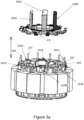
- FIG 3a is a partially-exploded view of a stator assembly in an electric supercharger according to a first embodiment of the invention.
- the stator assembly comprises three pairs of windings 203A-203C arranged in a circle. Each winding has an input termination 205 and an output termination 207 (only those on winding 203A are labelled in Figures 3a for clarity).
- the windings in each pair are on diametrically opposite sides of the circle and are connected in parallel such that the windings form opposite poles.
- the stator assembly is part of a switched reluctance motor (SRM) (not shown) and is arranged such that the pairs of windings can be selectively energised by a control module (not shown), to create a rotating magnetic field.
- the control module comprises a plurality of power modules (not shown), each power module being arranged to supply power to one of the pairs of windings.
- the first embodiment of the invention also comprises three pairs of busbars 209A-209C, to which reference will now be made:
- the pairs of busbars 209A-C are located in a busbar housing 210 located above the windings.
- Each pair of busbars 209A-C is associated with a respective pair of windings 103A-c.
- the different pairs 209A-C are highlighted by the shading on each pair (209A having light shading, 209B having dark shading, and 209C having no shading).
- the pair of busbars 209A comprises an input busbar 211 and an output busbar 213.
- the busbars 211, 213 are shaped to extend around the circumference of the stator assembly and are electrically isolated from one another by the busbar housing 210.
- the input busbar 211 connects the input terminations 205 of the two windings in the associated pair of windings 203A, whereas the output busbar 213 connects the output terminations 207 of the two windings in the pair of windings 203A.
- the connection to the winding terminations is made by crimping and welding the U-shaped connectors 212 on the busbar around the respective termination.
- Each busbar includes an upwardly extending tab 215 that acts as an electrical connector.
- the connector tabs 215 are arranged to be connected to a control module (not shown) for selectively energising the coils. It will be appreciated that by connecting the control module across the two connector tabs 215, the pair of windings 203A are electrically connected in parallel.
- the first embodiment of the invention has been found to have several advantages: Firstly, providing busbars to connect the pairs of windings has been found to facilitate relatively easy assembly of the stator assembly (and the switched reluctance motor more generally) as well as avoiding the need for complex layers of tracking to connect to a control module. Secondly, providing identical pairs of busbars is beneficial from the point of view of the manufacturing/assembly process and reduces the risk of electrical mis-match between pairs of busbars. Thirdly, in the first embodiment of the invention the pairs of busbars have a rotational symmetry of order 120 degrees about the longitudinal axis of the stator assembly (in other words, if the busbars were rotated 120 degrees about this axis, they would look identical). This has also been found to be beneficial because it simplifies the manufacturing/assembly process (especially for mass-production).
- FIG. 6 shows a busbar assembly for use in the stator assembly of Figures 3a-5 .
- the busbar assembly includes an electrically-insulating upper housing 217 that protects the pairs of busbars.
- the upper housing includes slots through which the connector tabs 215 protrude and attachment feet 219 for connection to a lower part of the stator assembly.
Description
- The present invention relates to an electric supercharger, and particularly an electric supercharger comprising a switched reluctance motor having a stator assembly.
- Busbar arrangements are disclosed by
JP 2005 065374 A FR 2 830 994 A1 EP 1 677 404 A2Figures 1a and1b show a previously suggested stator assembly for an electric supercharger. - The electric supercharger (not shown) comprises a switched reluctance motor. The
stator assembly 1 of the motor has sixwindings 3 arranged in three pairs (each pair comprising twowindings winding 3 has aninput termination 5 and anoutput termination 7 associated with it. These terminations are connectable to an energising source (not shown inFigure 1a ). In the stator assembly ofFigures 1a and1b , theterminations terminations input terminations 5 andoutput terminations 7 above each respective winding 3). - To control the energising of the windings, the stator assembly comprises a control module (indicated in general terms by
reference numeral 9 and shown inFigure 1b ). Thecontrol module 9 includes a microprocessor (not shown) for determining and controlling the sequence of energising thewindings 3, threepower control modules windings windings power control module windings 3B are shown inFigure 1b (with the exception of all threepower control modules 11A-C). - The tracking 13 (shown only in simplified form in
Figure 1b ) is formed of three PCB layers stacked above one another, each layer being associated with a respective pair ofwindings 3A-C. Each layer has afirst track 15 connecting together theinput terminations 5 of a pair of windings, asecond track 17 connecting together theoutput terminations 7 of the same pair of windings, andadditional tracks 19 linking the I/O terminals of therespective power module 11A-C with the first andsecond tracks - Such a tracking arrangement is complex and may therefore add cost to the control module. Furthermore, the tiered tracking results multiple layers of PCB and therefore in a relatively thick control module which can be undesirable from a cost perspective and/or from the perspective of the PCB's interaction with surrounding components of the supercharger.
- An arrangement that seeks to address the above-mentioned problems is shown in
Figure 2 and described inGB2510382 WO 2014/118557 . In that arrangement, the terminations of each pair ofwindings 103A-C are arranged such that theinput terminations 105 for the first and second windings are located adjacent one another and theoutput terminations 107 of the first and second windings are also located adjacent one another (within each pair of windings, the winding for forming one pole is indicated by the light-coloured wires, and the winding for forming the opposing pole is indicated by dark-coloured wires). By arranging the input terminations for the first and second windings adjacent one another and the output terminations of the first and second windings adjacent one another, the need for complex layers of tracking is removed. However, the arrangement inFigure 2 has been found to be difficult to efficiently manufacture/assemble. For example, locating and arranging the pairs of terminations in the suggested manner can be complex and has been found not to be well-suited to mass-production. Furthermore, the proximity of the wires of each of the windings, around the perimeter of the stator, may increase the risk of arcing or of other undesirable electrical contact between wires. - The present invention seeks to remove or mitigate at least some of the above-mentioned drawbacks.
- According to the invention there is provided an electric supercharger according to CLAIM 1. Providing the pair of busbars associated with each pair of windings, has been found to facilitate relatively easy assembly of the switched reluctance motor, whilst still avoiding the need for complex layers of tracking to connect to a control module.
- The input termination is the termination through which current is arranged to flow into the winding. The output termination is the termination through which current is arranged to flow out of the winding. For example there may be a voltage drop from the input termination to the output termination. The input and output terminations may be positive and negative terminations.
- The first pole may be a south pole and the second pole may be a north pole (or vice versa). It will be appreciated that the pole formed by each winding is dependent on the direction of the winding and/or the direction of the current flow through the winding.
- In principle, the first and second windings could be in any number of different relative positions. However, in more preferable embodiments of the invention, the first and second windings are located opposite one another.
- The pairs of busbars are substantially identical in shape. Such an arrangement is beneficial from the point of view of the manufacturing/assembly process. The pairs of busbars are substantially identical in their electrical properties. This has been found to be beneficial because it reduces the risk of electrical mis-match between pairs of busbars and simplifies the control of the switched reluctance motor (SRM).
- Within each pair of busbars, the input busbar may be different from the output busbar. For example the input and output busbars may be different lengths.
- The stator assembly has a longitudinal axis. The longitudinal axis is typically the axis of rotation of the rotor associated with the stator assembly. The pairs of busbars are rotationally symmetrical about the longitudinal axis of the stator assembly. Having a rotationally symmetrical arrangement has been found to be beneficial because it simplifies the manufacturing/assembly process (especially for mass-production). The pairs of busbars may have rotational symmetry of order 360/n (where n = the number of pairs of windings). For example for a 3-phase motor (having three pairs of windings) the pairs of busbars have rotational symmetry of order 120 degrees.
- Each input busbar may comprise a tab for forming an electrical connector. Each output busbar may comprise a tab for forming an electrical connector. The tabs may be upwardly extending for providing an electrical connection above the stator assembly. The tabs are preferably equally spaced around the perimeter of the stator assembly. Such an arrangement has been found to be beneficial from a manufacturing perspective and also provides a simple arrangement for connection to other parts of the SRM (for example to a control module for selectively energising each of the pairs of windings in the stator assembly).
- The stator assembly may further comprise a busbar housing. The busbar housing may be arranged to house the plurality of pairs of busbars such that the busbars are electrically insulated from one another. The busbar housing may comprise a series of insulated guide tracks, each guide track being arranged to receive and locate one of the busbars.
- Each busbar preferably extends in a substantially circumferential direction to connect the terminations of the respective winding.
- The motor is a switched reluctance motor (SRM). The motor includes a control module for controlling the energising of each of the pairs of windings in the stator assembly. The control module selectively energises the pairs of windings to generate a changing, and preferably a rotating, magnetic field. The control module may be arranged to selectively energise more than one pair of windings at any one time. The control module may comprise a plurality of power modules, each power module being arranged to power one of the pairs of windings. The waveform of the signal received by each pair of windings may be the same. The signals received by each pair of windings may be at least partially out of phase with one another.
- Each winding is preferably in the form of a coil of wire. The winding may be wrapped around a core.
- The windings are preferably arranged in a circle. The windings are arranged with the first and the second windings in each pair being diametrically opposite one another.
- The input and output terminations for each winding may be on the end of respective input and output wires to/from the winding. The input and output terminations of each winding are preferably located adjacent that winding (for example directly above the winding). The input and output wires of each winding preferably do not extend in a substantially circumferential direction such that the termination is circumferentially remote from its respective winding.
- The input terminations for the first and second windings may be located substantially opposite one another. The output terminations for the first and second windings may be located substantially opposite one another.
- The terminations may be positioned radially inwardly of the windings.
- The stator assembly comprises a multiplicity of pairs of windings. The stator assembly may comprise three pairs of windings.
- Various embodiments of the invention will now be described, by way of example only, with reference to the accompanying schematic drawings of which:
-
Figure 1a is a partially exploded perspective view of a previously suggested stator assembly in an electric supercharger; -
Figure 1b is a schematic plan view of the stator assembly ofFigure 1a , also showing a control module; -
Figure 2 is a perspective view of a stator assembly in another previously suggested arrangement; -
Figure 3a shows a partially-exploded view of a stator assembly in an electric supercharger according to a first embodiment of the invention; -
Figure 3b shows a perspective view of the pairs of busbars ofFigure 3a ; -
Figure 4 is a partially-exploded view of the stator assembly ofFigure 3a but with only one pair of busbars shown; -
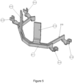
Figure 5 shows the pair of busbars ofFigure 4 in isolation; -
Figure 6 shows part of stator assembly ofFigure 3 , but with an upper part of a busbar housing installed. -
Figures 1a and1b show a previously suggested stator assembly in an electric supercharger (not shown). As explained above, the stator assembly comprises a control module including tracking 13 to connect each pair ofwindings power control module Figure 1b ) is formed of three PCB layers stacked above one another, each layer being associated with a pair ofwindings 3A-C. Such a tracking arrangement is complex and may therefore add cost to the stator assembly. Furthermore, the tiered tracking results in a relatively thick PCB which can be undesirable from a cost perspective and/or the PCB's interaction with surrounding components of the supercharger. -
Figure 2 shows another previously suggested stator assembly. Thestator assembly 101 comprises sixwindings 103 arranged in a circle. Thewindings 103 can be divided into pairs of diametricallyopposite windings 103A-C, each winding 103 in the pair being arranged to form an opposite pole to the other when energised by a control module. Within each pair of windings, the winding for forming one pole is indicated by the light-coloured wires, and the winding for forming the opposing pole is indicated by dark-coloured wires. - By arranging the input terminations for the first and second windings adjacent one another and the output terminations of the first and second windings adjacent one another, the need for complex layers of tracking is removed (and this has therefore been found to be an improvement over the arrangement in
Figures 1a and1b ). However, the arrangement inFigure 2 has been found to be difficult to efficiently manufacture/assemble. For example, locating and arranging the pairs of terminations in the suggested manner can be complex and has been found not to be well-suited to mass-production. Furthermore, the proximity of the wires of each of the windings, around the perimeter of the stator, may increase the risk of arcing or of other undesirable electrical contact between wires. - Reference will now be made to
Figures 3a to 6 , which show a stator assembly in an electric supercharger according to a first embodiment of the invention. -
Figure 3a is a partially-exploded view of a stator assembly in an electric supercharger according to a first embodiment of the invention. The stator assembly comprises three pairs ofwindings 203A-203C arranged in a circle. Each winding has aninput termination 205 and an output termination 207 (only those on winding 203A are labelled inFigures 3a for clarity). The windings in each pair are on diametrically opposite sides of the circle and are connected in parallel such that the windings form opposite poles. - The stator assembly is part of a switched reluctance motor (SRM) (not shown) and is arranged such that the pairs of windings can be selectively energised by a control module (not shown), to create a rotating magnetic field. The control module comprises a plurality of power modules (not shown), each power module being arranged to supply power to one of the pairs of windings.
- These features of the stator assembly are known per se (in this respect the assembly is substantially similar to the arrangement shown in
Figure 1a ). In contrast to known stator assemblies however, the first embodiment of the invention also comprises three pairs ofbusbars 209A-209C, to which reference will now be made:
The pairs ofbusbars 209A-C are located in abusbar housing 210 located above the windings. Each pair ofbusbars 209A-C is associated with a respective pair ofwindings 103A-c. InFigures 3a and3b thedifferent pairs 209A-C are highlighted by the shading on each pair (209A having light shading, 209B having dark shading, and 209C having no shading). - Each pair of the pairs of busbars is identical, so for the sake of clarity, reference is now made to
Figures 4 and5 , which show only one of the busbar pairs 209A. The pair ofbusbars 209A comprises aninput busbar 211 and anoutput busbar 213. Thebusbars busbar housing 210. - The
input busbar 211 connects theinput terminations 205 of the two windings in the associated pair ofwindings 203A, whereas theoutput busbar 213 connects theoutput terminations 207 of the two windings in the pair ofwindings 203A. The connection to the winding terminations is made by crimping and welding theU-shaped connectors 212 on the busbar around the respective termination. Each busbar includes an upwardly extendingtab 215 that acts as an electrical connector. - The
connector tabs 215 are arranged to be connected to a control module (not shown) for selectively energising the coils. It will be appreciated that by connecting the control module across the twoconnector tabs 215, the pair ofwindings 203A are electrically connected in parallel. - The first embodiment of the invention has been found to have several advantages: Firstly, providing busbars to connect the pairs of windings has been found to facilitate relatively easy assembly of the stator assembly (and the switched reluctance motor more generally) as well as avoiding the need for complex layers of tracking to connect to a control module. Secondly, providing identical pairs of busbars is beneficial from the point of view of the manufacturing/assembly process and reduces the risk of electrical mis-match between pairs of busbars. Thirdly, in the first embodiment of the invention the pairs of busbars have a rotational symmetry of order 120 degrees about the longitudinal axis of the stator assembly (in other words, if the busbars were rotated 120 degrees about this axis, they would look identical). This has also been found to be beneficial because it simplifies the manufacturing/assembly process (especially for mass-production).
-
Figure 6 shows a busbar assembly for use in the stator assembly ofFigures 3a-5 . The busbar assembly includes an electrically-insulatingupper housing 217 that protects the pairs of busbars. The upper housing includes slots through which theconnector tabs 215 protrude andattachment feet 219 for connection to a lower part of the stator assembly. - Whilst the present invention has been described and illustrated with reference to particular embodiments, it will be appreciated by those of ordinary skill in the art that the invention lends itself to many different variations not specifically illustrated herein. Where in the foregoing description, integers or elements are mentioned which have known, obvious or foreseeable equivalents, then such equivalents are herein incorporated as if individually set forth, provided that this is within the scope of the appended claims. Reference should be made to the claims for determining the true scope of the present invention. It will also be appreciated by the reader that integers or features of the invention that are described as preferable, advantageous, convenient or the like are optional and do not limit the scope of the independent claims.
Claims (9)
- A supercharger comprising a switched reluctance motor with a busbar assembly and a stator assembly, the stator assembly comprising a plurality of pairs of windings (203 A-C),each pair of windings comprising a first winding, for forming a first pole, connected in parallel with a second winding, for forming a second, diametrically opposite, pole,each winding having an input termination (205) and an output termination (207),wherein the busbar assembly further comprises a plurality of pairs of busbars (209 A-C), each pair of busbars being substantially identical and being associated with a respective pair of windings, the plurality of pairs of busbars is rotationally symmetrical about a longitudinal axis of the stator assembly, and each pair of busbars (209 A-C)comprising:an input busbar connecting the input terminations (205) of the first and second windings in the respective pair of windings (203 A-C), and an output busbar connecting the output terminations (207) of the first and second windings in the respective pair of windings (203 A-C)and wherein the motor includes a control module for selectively energising each of the pairs of windings in the stator assembly,and wherein the input busbar of each pair of busbars being radially inside the input terminations (205) of the first and second windings and the output busbar of each pair of busbars being radially inside the output terminations (207) of the first and second windings, and wherein the busbars are arranged to radially overlap one after the other in a circle.
- A supercharger according to any preceding claim, wherein each input busbar and each output busbar comprises a tab (215) for forming an electrical connection.
- A supercharger according to claim 2, wherein the tabs (215) are upwardly extending for providing an electrical connection above the stator assembly.
- A supercharger according claim 2 or claim 3, wherein the tabs (215) are equally spaced around the perimeter of the stator assembly.
- A supercharger according any preceding claim, wherein each busbar extends in a substantially circumferential direction to connect the terminations of the respective winding.
- A supercharger according to any preceding claim, wherein the windings are arranged with the first and the second windings in each pair being diametrically opposite one another.
- A supercharger according to any preceding claim, wherein the input (205) and output terminations (207) of each winding are located adjacent that winding.
- A supercharger according to claim 7 when dependent on claim 6, wherein the input terminations (205) for the first and second windings are located substantially opposite one another, and the output terminations (207) for the first and second windings are located substantially opposite one another.
- A supercharger according to claim 1, wherein the control module comprises a plurality of power modules, each power module being arranged to supply power to one of the pairs of windings.
Applications Claiming Priority (2)
| Application Number | Priority Date | Filing Date | Title |
|---|---|---|---|
| GB1520443.1A GB2544523B (en) | 2015-11-20 | 2015-11-20 | A stator and busbar assembly for an electric supercharger |
| PCT/EP2016/077899 WO2017085143A1 (en) | 2015-11-20 | 2016-11-16 | A stator and busbar assembly for an electric supercharger |
Publications (2)
| Publication Number | Publication Date |
|---|---|
| EP3378142A1 EP3378142A1 (en) | 2018-09-26 |
| EP3378142B1 true EP3378142B1 (en) | 2023-12-06 |
Family
ID=55133060
Family Applications (1)
| Application Number | Title | Priority Date | Filing Date |
|---|---|---|---|
| EP16797553.1A Active EP3378142B1 (en) | 2015-11-20 | 2016-11-16 | A stator and busbar assembly for an electric supercharger |
Country Status (3)
| Country | Link |
|---|---|
| EP (1) | EP3378142B1 (en) |
| GB (1) | GB2544523B (en) |
| WO (1) | WO2017085143A1 (en) |
Families Citing this family (3)
| Publication number | Priority date | Publication date | Assignee | Title |
|---|---|---|---|---|
| JP6947045B2 (en) * | 2018-01-15 | 2021-10-13 | 株式会社デンソー | Stator and method of manufacturing the stator |
| CN114144962A (en) * | 2019-07-31 | 2022-03-04 | 东芝开利株式会社 | Motor, compressor, refrigeration cycle device, and method for manufacturing motor |
| DE102021101149A1 (en) * | 2021-01-20 | 2022-07-21 | Schaeffler Technologies AG & Co. KG | high-voltage terminal |
Citations (6)
| Publication number | Priority date | Publication date | Assignee | Title |
|---|---|---|---|---|
| FR2830994A1 (en) * | 2001-10-16 | 2003-04-18 | Leroy Somer Moteurs | Winding for rotary electrical machine and stator using the winding, uses windings with tapered rectangular cross section for easier fitting into stator slots |
| JP2005065374A (en) * | 2003-08-08 | 2005-03-10 | Nissan Motor Co Ltd | Terminal wire connection structure of winding |
| EP1677404A2 (en) * | 2004-12-28 | 2006-07-05 | Hitachi, Ltd. | Motor for electric power steering and method for manufacturing the same |
| WO2014118557A2 (en) * | 2013-02-01 | 2014-08-07 | Valeo Air Management Uk Limited | A stator assembly for an electric supercharger |
| US20150015100A1 (en) * | 2012-02-13 | 2015-01-15 | Brose Fahrzeugteile GmbH & Co. Kommanditgesellschaft, Würzburg | Stator Arrangement And Electric Machine |
| WO2015093138A1 (en) * | 2013-12-16 | 2015-06-25 | 三菱電機株式会社 | Mechatronic driver and method for manufacturing same |
Family Cites Families (2)
| Publication number | Priority date | Publication date | Assignee | Title |
|---|---|---|---|---|
| JP5001723B2 (en) * | 2007-06-12 | 2012-08-15 | 富士重工業株式会社 | Electric motor |
| WO2009113633A1 (en) * | 2008-03-13 | 2009-09-17 | 日本電産株式会社 | Bus bar terminal, bus bar unit, and motor |
-
2015
- 2015-11-20 GB GB1520443.1A patent/GB2544523B/en active Active
-
2016
- 2016-11-16 EP EP16797553.1A patent/EP3378142B1/en active Active
- 2016-11-16 WO PCT/EP2016/077899 patent/WO2017085143A1/en active Application Filing
Patent Citations (6)
| Publication number | Priority date | Publication date | Assignee | Title |
|---|---|---|---|---|
| FR2830994A1 (en) * | 2001-10-16 | 2003-04-18 | Leroy Somer Moteurs | Winding for rotary electrical machine and stator using the winding, uses windings with tapered rectangular cross section for easier fitting into stator slots |
| JP2005065374A (en) * | 2003-08-08 | 2005-03-10 | Nissan Motor Co Ltd | Terminal wire connection structure of winding |
| EP1677404A2 (en) * | 2004-12-28 | 2006-07-05 | Hitachi, Ltd. | Motor for electric power steering and method for manufacturing the same |
| US20150015100A1 (en) * | 2012-02-13 | 2015-01-15 | Brose Fahrzeugteile GmbH & Co. Kommanditgesellschaft, Würzburg | Stator Arrangement And Electric Machine |
| WO2014118557A2 (en) * | 2013-02-01 | 2014-08-07 | Valeo Air Management Uk Limited | A stator assembly for an electric supercharger |
| WO2015093138A1 (en) * | 2013-12-16 | 2015-06-25 | 三菱電機株式会社 | Mechatronic driver and method for manufacturing same |
Also Published As
| Publication number | Publication date |
|---|---|
| GB201520443D0 (en) | 2016-01-06 |
| WO2017085143A1 (en) | 2017-05-26 |
| EP3378142A1 (en) | 2018-09-26 |
| GB2544523B (en) | 2022-02-09 |
| GB2544523A (en) | 2017-05-24 |
Similar Documents
| Publication | Publication Date | Title |
|---|---|---|
| US8154166B2 (en) | Dual layer winding pattern | |
| EP2941815B1 (en) | A stator assembly for an electric supercharger | |
| US8188632B2 (en) | Miniature motor, and its manufacturing method | |
| CN102782986B (en) | The stator of motor and manufacture method thereof | |
| US20130076175A1 (en) | Connection module for a bar wound stator assembly and method of manufacturing a bar wound stator assembly | |
| CN105932848A (en) | Stator Component Group For Electric Motor | |
| EP3378142B1 (en) | A stator and busbar assembly for an electric supercharger | |
| CN101958588A (en) | The stator and the manufacture method thereof that are used for the electric rotating machine device | |
| KR20150061452A (en) | Concentrated Type motor | |
| US9362796B2 (en) | Electricity collection and distribution ring and electric motor | |
| CN103683618B (en) | Power distribution unit and electric rotating machine | |
| US20200280231A1 (en) | Stator | |
| CN111555506A (en) | Motor stator and motor | |
| CN110476325B (en) | Rotating electrical machine | |
| CN111247717A (en) | Stator device for an electric motor having a terminal plate and use of the stator device | |
| JP2017077085A (en) | Power collection and distribution ring, electric motor, and manufacturing method for electric motor | |
| US11050313B2 (en) | Stator and motor comprising same | |
| CN106936231A (en) | Stator and multi-phase brushless motor | |
| KR20230034943A (en) | Stators and electric machines for electric machines | |
| US11114913B2 (en) | Rotating electric machine | |
| CN114649883B (en) | Three-phase stator assembly | |
| CN212033859U (en) | Motor stator and motor | |
| CN214543854U (en) | Motor stator winding, stator and motor | |
| CN212033861U (en) | Motor stator and motor | |
| CN214755794U (en) | Electric machine |
Legal Events
| Date | Code | Title | Description |
|---|---|---|---|
| STAA | Information on the status of an ep patent application or granted ep patent |
Free format text: STATUS: UNKNOWN |
|
| STAA | Information on the status of an ep patent application or granted ep patent |
Free format text: STATUS: THE INTERNATIONAL PUBLICATION HAS BEEN MADE |
|
| PUAI | Public reference made under article 153(3) epc to a published international application that has entered the european phase |
Free format text: ORIGINAL CODE: 0009012 |
|
| STAA | Information on the status of an ep patent application or granted ep patent |
Free format text: STATUS: REQUEST FOR EXAMINATION WAS MADE |
|
| 17P | Request for examination filed |
Effective date: 20180529 |
|
| AK | Designated contracting states |
Kind code of ref document: A1 Designated state(s): AL AT BE BG CH CY CZ DE DK EE ES FI FR GB GR HR HU IE IS IT LI LT LU LV MC MK MT NL NO PL PT RO RS SE SI SK SM TR |
|
| AX | Request for extension of the european patent |
Extension state: BA ME |
|
| DAV | Request for validation of the european patent (deleted) | ||
| DAX | Request for extension of the european patent (deleted) | ||
| STAA | Information on the status of an ep patent application or granted ep patent |
Free format text: STATUS: EXAMINATION IS IN PROGRESS |
|
| 17Q | First examination report despatched |
Effective date: 20190605 |
|
| STAA | Information on the status of an ep patent application or granted ep patent |
Free format text: STATUS: EXAMINATION IS IN PROGRESS |
|
| STAA | Information on the status of an ep patent application or granted ep patent |
Free format text: STATUS: EXAMINATION IS IN PROGRESS |
|
| GRAP | Despatch of communication of intention to grant a patent |
Free format text: ORIGINAL CODE: EPIDOSNIGR1 |
|
| STAA | Information on the status of an ep patent application or granted ep patent |
Free format text: STATUS: GRANT OF PATENT IS INTENDED |
|
| RIC1 | Information provided on ipc code assigned before grant |
Ipc: H02K 7/18 20060101ALN20230906BHEP Ipc: F02B 33/00 20060101ALN20230906BHEP Ipc: H02K 19/10 20060101ALN20230906BHEP Ipc: H02K 5/22 20060101ALI20230906BHEP Ipc: F02B 39/10 20060101ALI20230906BHEP Ipc: H02K 3/52 20060101AFI20230906BHEP |
|
| INTG | Intention to grant announced |
Effective date: 20230925 |
|
| GRAS | Grant fee paid |
Free format text: ORIGINAL CODE: EPIDOSNIGR3 |
|
| GRAA | (expected) grant |
Free format text: ORIGINAL CODE: 0009210 |
|
| STAA | Information on the status of an ep patent application or granted ep patent |
Free format text: STATUS: THE PATENT HAS BEEN GRANTED |
|
| AK | Designated contracting states |
Kind code of ref document: B1 Designated state(s): AL AT BE BG CH CY CZ DE DK EE ES FI FR GB GR HR HU IE IS IT LI LT LU LV MC MK MT NL NO PL PT RO RS SE SI SK SM TR |
|
| REG | Reference to a national code |
Ref country code: GB Ref legal event code: FG4D |
|
| REG | Reference to a national code |
Ref country code: DE Ref legal event code: R096 Ref document number: 602016084599 Country of ref document: DE |
|
| REG | Reference to a national code |
Ref country code: CH Ref legal event code: EP |
|
| REG | Reference to a national code |
Ref country code: IE Ref legal event code: FG4D |
|
| REG | Reference to a national code |
Ref country code: LT Ref legal event code: MG9D |
|
| PG25 | Lapsed in a contracting state [announced via postgrant information from national office to epo] |
Ref country code: GR Free format text: LAPSE BECAUSE OF FAILURE TO SUBMIT A TRANSLATION OF THE DESCRIPTION OR TO PAY THE FEE WITHIN THE PRESCRIBED TIME-LIMIT Effective date: 20240307 |
|
| REG | Reference to a national code |
Ref country code: NL Ref legal event code: MP Effective date: 20231206 |
|
| PG25 | Lapsed in a contracting state [announced via postgrant information from national office to epo] |
Ref country code: LT Free format text: LAPSE BECAUSE OF FAILURE TO SUBMIT A TRANSLATION OF THE DESCRIPTION OR TO PAY THE FEE WITHIN THE PRESCRIBED TIME-LIMIT Effective date: 20231206 |