EP3377979B1 - System und verfahren zur skalierbaren cloudbasierten sensorkalibrierung - Google Patents
System und verfahren zur skalierbaren cloudbasierten sensorkalibrierung Download PDFInfo
- Publication number
- EP3377979B1 EP3377979B1 EP16867335.8A EP16867335A EP3377979B1 EP 3377979 B1 EP3377979 B1 EP 3377979B1 EP 16867335 A EP16867335 A EP 16867335A EP 3377979 B1 EP3377979 B1 EP 3377979B1
- Authority
- EP
- European Patent Office
- Prior art keywords
- calibration
- sensor
- settings
- coefficients
- sensors
- Prior art date
- Legal status (The legal status is an assumption and is not a legal conclusion. Google has not performed a legal analysis and makes no representation as to the accuracy of the status listed.)
- Active
Links
Images





Classifications
-
- G—PHYSICS
- G01—MEASURING; TESTING
- G01D—MEASURING NOT SPECIALLY ADAPTED FOR A SPECIFIC VARIABLE; ARRANGEMENTS FOR MEASURING TWO OR MORE VARIABLES NOT COVERED IN A SINGLE OTHER SUBCLASS; TARIFF METERING APPARATUS; MEASURING OR TESTING NOT OTHERWISE PROVIDED FOR
- G01D18/00—Testing or calibrating apparatus or arrangements provided for in groups G01D1/00 - G01D15/00
-
- G—PHYSICS
- G01—MEASURING; TESTING
- G01D—MEASURING NOT SPECIALLY ADAPTED FOR A SPECIFIC VARIABLE; ARRANGEMENTS FOR MEASURING TWO OR MORE VARIABLES NOT COVERED IN A SINGLE OTHER SUBCLASS; TARIFF METERING APPARATUS; MEASURING OR TESTING NOT OTHERWISE PROVIDED FOR
- G01D18/00—Testing or calibrating apparatus or arrangements provided for in groups G01D1/00 - G01D15/00
- G01D18/008—Testing or calibrating apparatus or arrangements provided for in groups G01D1/00 - G01D15/00 with calibration coefficients stored in memory
-
- H—ELECTRICITY
- H04—ELECTRIC COMMUNICATION TECHNIQUE
- H04L—TRANSMISSION OF DIGITAL INFORMATION, e.g. TELEGRAPHIC COMMUNICATION
- H04L67/00—Network arrangements or protocols for supporting network services or applications
- H04L67/01—Protocols
- H04L67/10—Protocols in which an application is distributed across nodes in the network
-
- H—ELECTRICITY
- H04—ELECTRIC COMMUNICATION TECHNIQUE
- H04L—TRANSMISSION OF DIGITAL INFORMATION, e.g. TELEGRAPHIC COMMUNICATION
- H04L67/00—Network arrangements or protocols for supporting network services or applications
- H04L67/01—Protocols
- H04L67/12—Protocols specially adapted for proprietary or special-purpose networking environments, e.g. medical networks, sensor networks, networks in vehicles or remote metering networks
Definitions
- the present disclosure relates to configuring sensors, and, more specifically, to the calibration and/or re-calibration of sensors utilizing one or more calibration parameter settings obtained from a computing network.
- Sensor devices typically combine a sensing element, analog interface circuit, an analog-to-digital converter (ADC), and a bus interface, all-in-one housing, and may include additional functionality, such as self-testing, self-identification, self-validation, or self-adaptation, by way of example.
- ADC analog-to-digital converter
- the single-housing sensor system may also be configured to perform signal processing and multi-sensing capabilities.
- Typical configurations of these sensors may include an analog front end (AFE), analog-to-digital converter (ADC), and digital signal processing (DSP) circuit and control.
- AFE analog front end
- ADC analog-to-digital converter
- DSP digital signal processing
- the AFE module typically includes a front-end signal conditioning circuit, a programmable gain amplifier (PGA) and an analog filter.
- a post-processing DSP circuit may include different types of digital filters. Due to silicon deep sub-micron manufacturing process limitations for devices (e.g., sensors), and the precision requirements of the circuit design specifications for different industry standards, the analog and digital circuits implemented into these sensor devices or smart sensor system modules often include dedicated calibration circuits and common system interfaces for calibration purposes.
- a dedicated memory component such as a non-volatile EEPROM
- predefined calibration coefficients may also include AFE programmable gain coefficients, as well as calibration configuration and calibration output data.
- Some analog filters may also be calibrated with predefined coefficient settings through the system calibration interface.
- DSP circuits may include different digital filters such as a finite impulse response (FIR) or Infinite Impulse Response (IIR) circuits, which can also be implemented with the system calibration interface. Using this configuration, calibration coefficient settings can thus be loaded into the dedicated memory storage.
- FIR finite impulse response
- IIR Infinite Impulse Response
- Calibration of specific-use sensors may be costly and inefficient, as it may typically require individual calibration of each sensor geared to the specific use.
- a generic sensor calibration platform may be advantageous for accommodating various types of calibration parameters, particularly in cases where large quantities of sensor devices are produced in a manufacturing process.
- calibration platforms may involve the calibration of multiple different types of sensors, wherein each type of sensor may require multiple different predefined calibration coefficient settings, calibration configurations, and calibration output.
- Such manufacturing process configurations may require very large amounts of dedicated sensor calibration parameter settings and storage areas.
- incremental accumulation and periodic updates of the sensor calibration parameter settings back to the calibration system would be costly to implement using strictly conventional manufacturing calibration systems.
- apparatuses, systems and methods are needed to improve the effectiveness and efficiency of programming and updating calibration parameters for sensors in a scalable environment.
- computer systems for calibrating one or more sensors, comprising: a processor; a communication interface, operatively coupled to the processor, the communication interface configured to receive a calibration parameter set from a computer network; a plurality of calibration system bus interfaces, operatively coupled to the processor to communicate with a plurality of calibration modules corresponding to each of the one or more sensors, each of the calibration system bus interfaces being configured to transmit the received calibration parameter set to a particular one of the plurality of calibration modules of the one or more sensors, wherein each of the calibration bus interfaces is further configured to receive calibration output data from the respective one or more sensors, corresponding to the particular calibration module, in response to the calibration parameter set transmitted, and wherein the communications interface is configured to transmit the calibration output data to the computer network for generating a new calibration parameter set.
- methods for calibrating one or more sensors in a system, comprising: receiving a calibration parameter set for the one or more sensors from a computer network; transmitting the received calibration parameter set to a particular one of a plurality of calibration modules corresponding to each of the one or more sensors using one of a plurality of calibration system bus interfaces; generating calibration output data from the respective one or more sensors, corresponding to the particular calibration module, in response to the calibration parameter set; transmitting the calibration output data to the computer network; and receiving a new calibration parameter set for the plurality of calibration modules of the one or more sensors in response to the calibration output data.
- methods for calibrating one or more sensors in a system, comprising: receiving a plurality of calibration parameter sets for a plurality of calibration modules corresponding to each of a plurality sensors from a computer network; successively transmitting each of the received calibration parameter sets to at least one of a plurality of calibration modules of each of the plurality of sensors using a plurality of calibration system bus interfaces; successively receiving and storing calibration output data from each of the respective sensors, corresponding to the at least one of the calibration modules selected, in response to each calibration parameter set transmitted; transmitting the calibration output data to the computer network; and receiving a new calibration parameter set for the plurality of calibration modules corresponding to the one or more sensors in response to the calibration output data.
- an element or layer is referred to as being “on,” “engaged to,” “connected to,” or “coupled to” another element or layer, it may be directly on, engaged, connected or coupled to the other element or layer, or intervening elements or layers may be present.
- an element is referred to as being “directly on,” “directly engaged to,” “directly connected to,” or “directly coupled to” another element or layer, there may be no intervening elements or layers present.
- Other words used to describe the relationship between elements may be interpreted in a like fashion ( e.g ., “between” versus “directly between,” “adjacent” versus “directly adjacent,” etc.).
- the term “and/or” includes any and all combinations of one or more of the associated listed items.
- first, second, third, etc. may be used herein to describe various elements, components, regions, layers and/or sections, these elements, components, regions, layers and/or sections should not be limited or subjected to a particular order by these terms. These terms may be used only to distinguish one element, component, region, layer or section from another element, component, region, layer or section. Terms such as “first,” “second,” and other numerical terms when used herein do not imply a sequence or order unless clearly indicated by the context. Thus, a first element, component, region, layer or section discussed below could be termed a second element, component, region, layer or section without departing from the teachings of the exemplary embodiments.
- Various apparatuses, systems and methods may be provided for a cloud-based calibration storage and distribution platform. Such apparatuses, systems and methods can be used to store, download, upload and share multiple device calibration data, at the time of manufacturing, and/or for use after a calibrated device is out in the field, for example.
- a sensor device or smart sensor module for example, may be configured to receive, transmit and/or update calibration parameter data stored in a secure cloud environment, and the device and/or its data may be made available for cloud-based analytics processing.
- Embodiments of the invention may be adapted to cover a wide range of sensor device types or smart sensor system modules, for example.
- each sensor device or smart sensor module subjected to calibration setup and/or update may have multiple predefined calibration parameter settings recalled and/or downloaded from a computer network and applied to individual sensor devices or smart sensor modules.
- the calibration parameters may further be managed by a system calibration operations programming sequence, such as from a calibration system computer.
- ⁇ can be uploaded and stored in the computer network (e.g., cloud) for any number of applications including, but not limited to, future referencing in analytics processing of data across multiple manufacturing sites, comparing updated calibration data to original sensor manufacturer data, and/or for optimization in the field once the device becomes commercially available.
- Illustrative sensor calibration parameter settings may include, but are not limited to, in-circuit sensor calibration coefficient settings, calibration configuration settings, calibration output, and other calibration related parameters.
- Identical or similar stored sensor implementation circuit calibration parameters may also be shared in real-time through computer network storage across multiple manufacturing sites, and for post-manufacturing data and analytics processing.
- FIGS. 1A-1D A sensor system 100 is shown in FIGS. 1A-1D of an illustrative embodiment.
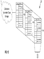
- Sensor system 100 may be configured as a generic calibration parameter system, including secure cloud storage for storing calibration parameters (see FIG. 1C ), for example.
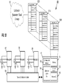
- a system computer or computing device 101 is shown in an illustrative embodiment, wherein computing device 101 includes a communication interface 102, a calibration system bus 103, a memory 104, a peripheral interface 105 and one or more processors 106, including, but not limited to, a central processing unit (CPU), co-processor(s), graphics processing unit (GPU), digital signal processor (DSP) and microcontrollers.
- Communication interface 102 may include any suitable interface (e.g., TCP/IP) allowing communication to/from computer 101 to a computer network ("B") and to sensors ("A”) via Calibration System Bus 103.
- System bus 103 may be configured to pass communication and data to/from sensors ("A") and may be based on any suitable platform, including, but not limited to, Inter-IC bus (I 2 C), serial peripheral interface (SPI), the IEEE 1461 standard (e.g., IEEE1451.2, and IEEE1451.3), and the Universal Micro-Sensor Interface (UMSI), that may include an Intra-Module Multi-element (IM 2 ) interface.
- I 2 C Inter-IC bus
- SPI serial peripheral interface
- IEEE 1461 e.g., IEEE1451.2, and IEEE1451.3
- UMSI Universal Micro-Sensor Interface
- sensor system 100 may be configured to have platform-specific communications to accommodate platform-specific sensors (e.g., I 2 C).
- sensor system 100 may be configured to accommodate multiple platform-specific sensors in a plug-and-play environment (e.g., UMSI).
- the sensor arrangement may be configured as one or more sensor devices and/or smart sensor modules arranged for calibration in a manufacturing setup.
- Each of the sensor devices and/or smart sensor modules may include sensor elements (SE) 110-112 and calibration modules 107-109 arranged as two portions.
- SE sensor elements
- 107-108 respective calibration module
- a computer program product in accordance with certain embodiments may include a tangible computer usable medium (e.g., RAM, ROM, an optical disc, a USB drive, or the like) having computer-readable program code embodied therein, wherein the computer-readable program code is adapted to be executed by a processor (working in connection with an operating system and/or executable software) to implement one or more functions and methods as described below.
- the program code may be implemented in any desired language, and may be implemented as machine code, assembly code, byte code, interpretable source code or the like (e.g., via C, C++, C#, Java, Actionscript, Objective-C, Javascript, CSS, XML, etc.).
- the sensor circuit arrangement of FIG. 1B may further include front end sensing element(s), (e.g., resistors formed in a Wheatstone bridge configuration for a pressure sensor), followed by an analog front end (AFE) signal conditioning circuit, which may include programmable gain amplifier(s) and analog filters, followed by the analog-to-digital converter (ADC). Such an arrangement may further include digital signal processing (DSP) circuitry for post-processing operations, for example.
- each sensor element e.g., 110
- a respective calibration module e.g., 107 to send/receive data including, but not limited to, calibration parameter data.
- Each calibration module (e.g., 107-109) may be connected to a common bus (as shown in FIG. 1B ) through a device calibration station (114) to couple to computing device 101 ("A") for receiving such data.
- the calibration modules may be connected to a plurality of buses for communicating with computing device 101.
- computing device 101 includes a plurality of system buses (103) for facilitating such communication.
- a computer network arrangement is shown for sensor system 100 according to an illustrative embodiment.
- a cloud storage system 113 may be arranged to receive, distribute, update and/or otherwise process and communicate calibration parameters for sensor modules, such as those illustrated in the example of FIG. 1B .
- the term "cloud” as used herein refers to a cloud infrastructure that may be generally defined as a collection of hardware and tangibly-embodied software that enables characteristics of cloud computing.
- illustrative cloud characteristics may include on-demand self-service (e.g., a user may unilaterally provision computing capabilities, such as server time and network storage, as needed automatically without requiring human interaction with each service provider); broad network access (e.g., capabilities are available over the network and accessed through standard mechanisms that promote use by heterogeneous thin or thick client platforms); resource pooling (e.g., the provider's computing resources, such as processing, memory, and network bandwidth, may be pooled to serve multiple users using a multi-tenant model, with different physical and virtual resources dynamically assigned and reassigned according to consumer demand); rapid elasticity (e.g., capabilities can be elastically provisioned and released, in some cases automatically, to scale rapidly outward and inward commensurate with demand); and measured service (e.g., automatically controlling and optimizing resource use by leveraging metering capabilities at some level of abstraction appropriate to the type of service).
- on-demand self-service e.g., a user may unilaterally provision computing capabilities, such as server time and
- cloud infrastructure 113 of sensor system 100 may be viewed as containing a physical layer and an abstraction layer.
- the physical layer may include hardware resources to support the cloud services being provided, and may typically include server, storage and network components.
- the abstraction layer may include software deployed across the physical layer, which manifests the cloud characteristics such as those discussed above.
- the abstraction layer sits above the physical layer.
- the cloud infrastructure may be deployed as a private cloud (e.g., provisioned for exclusive use by a single organization), a community cloud (e.g., provisioned for exclusive use by a specific community of users from organizations having shared interests), a public cloud (e.g., provisioned for open use by the general public), or a hybrid cloud (e.g., a composition of two or more distinct cloud infrastructures).
- a private cloud e.g., provisioned for exclusive use by a single organization
- a community cloud e.g., provisioned for exclusive use by a specific community of users from organizations having shared interests
- a public cloud e.g., provisioned for open use by the general public
- a hybrid cloud e.g., a composition of two or more distinct cloud infrastructures
- calibration parameter storage 113 also includes security protocols, such as encryption, for providing a secure communication platform.
- security protocols such as encryption
- a data analytics engine may also be provided as part of calibration parameter storage 113 in some illustrative embodiments.
- calibration parameter storage 113 includes one or more databases 110A, 111A, and 112A, (or 110B, 111B, and 112B in FIG. 4C ) relating to individual sensor modules 110-112.
- the one or more databases configured for each sensor module 110-112 may be configured to store a plurality (1-m) of sensor calibration parameters ("sensor calibration parameter set 1- m "), which may be uploaded, modified and transmitted to and from sensor system 100, for example.
- sensor calibration parameter set 1- m a plurality (1-m) of sensor calibration parameters
- different calibration parameter settings may be applied to the analog/or and digital implementation circuits of a sensor through the plurality of system calibration bus interfaces 103.
- a generic sensor calibration cloud based platform may support multiple calibration parameter settings for multiple different types of sensors, as will be apparent to those skilled in the pertinent arts in light of the disclosure herein, wherein each individual sensor device calibration output may be accumulated together with the calibration parameters and stored back into calibration parameter storage 113.
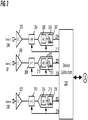
- a sensor arrangement for a generic calibration platform having a plurality of sensors that may be coupled (“A") to the computing device 101 of the sensor system of FIG. 1A via a device calibration station 230, in an illustrative embodiment.
- the embodiment in FIG. 1B may be configured to represent the embodiment illustrated in FIG. 2 , for example.
- a plurality of devices 200-202 having respective sensor elements (203, 208, 223) are coupled to a device calibration station 230, which may be configured to load and/or provide (see 217-219) device calibration configuration data to circuitry of each sensor in the sensor arrangement.
- Device calibration station 230 may also be configured to receive sensor readings (220-222) for transmission to the computing device 101 via a calibration system bus and further to calibration parameter storage 113.
- Each of the sensor devices or smart sensor modules of the sensor arrangement of FIG. 2 may include a sensor front-end for signal conditioning, wherein each front end may include an analog front end (AFE) (204, 209, 213), a digital end portion (207, 212, 216) an analog-to-digital converter (ADC) (205, 210, 214), and a digital signal processing (DSP) unit (206, 211, 215).
- the sensor calibration interface for the sensor arrangement may be configured to couple the AFE block and the digital end to the sensor device calibration station 230.
- the sensor devices or smart sensor modules may be configured in a single channel arrangement for a respective sensor device or smart sensor module calibration, as shown in FIG. 2 .
- shared buses/channels may be utilized as well. Such arrangements advantageously allow scalability of multiple sensor devices or smart sensor modules, replicated into scalable multiple channels as illustrated in FIG. 2 (devices 2-n).
- Scalable multi-site sensor calibration configurations may be also advantageous when a generic sensor calibration platform is to be replicated and operated in a concurrent fashion.
- the calibration parameter storage 113 may be accessed, in a synchronous, simultaneous, and/or ad-hoc manner, by multiple calibration system computers associated with different calibration platforms (see FIGS. 4A-4B ).
- a generic sensor calibration platform may be configured to cover a wide range of sensor devices or smart sensor modules including, but not limited to, accelerometers, gyroscopes, magnetometers, motion sensors, eCompass, temperature, humidity, environmental, and other specialty sensors as well.
- parameters from the calibration parameter storage 113 may include sensor calibration coefficients from the parameter settings, and may further include any other suitable coefficients, including, but not limited to, analog programmable gain coefficients settings, analog filter coefficients settings, digital filter coefficients settings, DSP algorithmic implementation coefficients settings, sensor manufacturing process correlated coefficients settings, sensor end user events correlated coefficients settings, sensor device temperature dependent analytic coefficients settings, sensor device voltage dependent analytic coefficients settings, sensor device process dependent analytic coefficients settings, sensor fusion implementation correlated coefficients settings, smart sensor module manufacturing process phase correlated coefficients settings, smart sensor module manufacturing end user events correlated coefficients settings, and so on. As suggested in FIG.
- the scalability of the calibration parameter set may be characterized by sensor system 100 as a "sensor calibration parameter set m", where the parameter sets of 1 to m are supported for a scalable implementation in an illustrative embodiment.
- FIG. 4A also illustrates a corresponding system calibration software operations flow.
- the calibration parameter storage 113 particularly when configured under a cloud computing platform arrangement, provides a common utility source for maximizing the effectiveness of shared resources.
- cloud resources may be shared by multiple users and/or also dynamically reallocated per demand.
- multiple sensor calibration sites may be provided access to individual test platform configuration parameters, unique sensor device or smart sensor module individualized configurations, along with unique coefficient and parameter settings information and the like, which are dynamically reallocated.
- one illustrative technique for calibration can be generally described as an activity where the instrument being tested (e.g., sensor) is compared to a known reference value.
- the instrument being tested e.g., sensor
- sensor devices may produce data that may be inaccurate, erroneous, and/or misleading.
- error introduced into sensor output data including those caused by the sensor device circuit or hardware itself.
- hardware error can be caused by the sensor hardware implementation at a circuit level, the sensor device component, and/or sensor drift (sensors' characteristics change by age or damage).
- Sensor product manufacturing tolerances are typically derived and compensated for by calibrating the sensor produce during a final production manufacturing process, where the calibration data may be utilized when a system is powered up.
- Environmental parameters for a particular application in the field may also create a need for specialized testing and calibration. Such environmental factors may include circuit component aging, temperature, humidity, and signal level and bias reference, etc.
- Certain sensor circuits may contain control or average information, which can be periodically stored in memory. These factors may be accounted for using a combination or accumulation of calibration parameters that are stored in the cloud-based calibration parameter storage 113.
- the calibration parameter settings may also include field calibration data.
- a simple example of field calibration data may include a sensor temperature and compensation adjustment setting.
- a more complex example of field calibration data may include data reflecting end user application events.
- the SCO would be the result of nine total measurements for the calibration, which, expanded for the range of coefficients in the example, essentially requires second order equation computation/processing.
- a computing device 101 fetches a first initial sensor calibration parameter set from the calibration parameter storage 113 in block 302.
- each sensor device is operated using the fetched calibration parameter from block 302, where decision block 304 determines if the last sensor of the device has been operated using the fetched calibration parameter. If not ("NO"), the process of 300 increments the sensor device index in block 305 to move to the next sensor, and the next sensor is subjected to the calibration of block 303. This process may be repeated until the last sensor is calibrated, and decision block 304 determined that the last sensor was calibrated (“YES").
- the process of 300 determines in decision block 306 if the calibration parameter setting used in the calibration of block 303 was the last calibration parameter setting stored and available from calibration parameter storage 113. If further calibration parameter settings are available ("NO"), the process moves to block 307, wherein the sensor calibration parameter setting is incremented by one and the next calibration parameter setting is fetched in block 308. Using the next calibration parameter setting, sensor device calibration is performed in block 303 and again recursively operated through the calibration routines until the last device N is completed ("YES”) in block 306.
- the process 300 determines again in decision block 306 if the last calibration parameter setting has been used, and, if not, the process 300 proceeds to blocks 307, 308 and 303 to increment the sensor calibration parameter settings by one, fetch the new calibration parameter, and perform sensor device calibration in block 303 as before.
- the process may repeat until decision block 306 determines that the last calibration parameter setting was used ("YES") at which point all of the device calibration output data is transmitted/stored in calibration parameter storage 113 as shown in block 309. Once stored, the process may end at block 310.
- a “baseline” may be measured and stored in the calibration system.
- a baseline may be defined as an initial intrinsic reference point of the system from which the sensor element is initially set.
- the baseline value for each sensor element may be initialized, maintained and properly stored in calibration parameter storage 113 for subsequent periodic updates. Maintaining the baseline may be important during a sensor calibration operation sequence due to the fact that the system may be impacted by external factors, such as temperature, moisture, humidity, location etc., as well as calibration system setup parameters, such as supply voltage and current. Without maintaining a baseline, such extrinsic factors may cause the sensor element reference baseline measurement results to drift. If this drift occurs during a calibration process and is not taken into account, sensor element measurement errors may exist. As such, calibration adjustment of the baseline for the sensor element measurement setup and adjustment should be performed as part of the sensor calibration process.
- the various coefficients in the calibration equation may be determined beforehand.
- the AFE gain and offset parameters may be initially determined.
- the calibration process may determine two sets of unknown variables: (1) AFE gain and offset values, and (2) calibration equation coefficient values.
- Sensor front end circuit calibration may be performed as a two-step process, where the first step determines the sensor AFE scaling factors, and the second step determines the digital circuit equation coefficients.
- Determining the unknown variables may require appropriate calibration equipment in the production line, which also involves time on the production line.
- the calibration of every sense element involves cost. This cost is proportional to the time spent in the calibration process.
- the calibration process may involve a tradeoff between the number of unknown coefficients, which directly translates to the end-accuracy of the exemplary pressure sensor (as described herein), and the time spent in the calibration process, which translates to cost.
- the calibration may be performed after the sense element is connected to a signal conditioner that may be part of a sensor calibration module.
- Sensor AFE circuit calibration may be performed as a multi-step process.
- the gain and the offset calibration parameter in the AFE may be adjusted while the sense element is exposed to certain pressure and temperature conditions.
- the sensor sense element (SE) is first exposed to a temperature T1 and pressure P1 that may represent the minimum pressure that the sense element has to measure.
- the AFE offset calibration parameter may then be adjusted so that the AFE output is as close as possible to the minimum ADC input value.
- the pressure may then be changed to P2 that may represent the maximum pressure that the sense element has to measure.
- the gain may be adjusted so that the AFE output is as close as possible to the maximum ADC input value.
- the offset scales with the sensor AFE gain parameter, which is the case with certain programmable gain amplifier (PGA) gain-setting parameters.
- PGA programmable gain amplifier
- the sensor digital circuit calibration coefficients may be determined. Determining the actual digital coefficients parameter may be performed as another multi-step process. For example, a sense element may be exposed to different temperature and pressure conditions and the ADC outputs are recorded. The recorded ADC values may then be used to compute digital coefficients offline. The number of temperature and pressure set points, at which the digital representation of temperature and the bridge output are recorded, may depend on the number of coefficients used.
- the present disclosure shows a generic sensor calibration platform that may be extended for use by other non-sensor device front end signal conditioning circuit products that encompass similar calibration requirements. It may also be utilized as a manufacturing-centric standard service item for use across multiple sites, and as a technique for optimizing calibration parameter settings in the field.
- FIGS. 4A and 4B show an illustrative embodiment wherein multiple sites (e.g., "Site 1" and "Site 2") utilize the sensor calibration techniques disclosed herein.
- Each site may include computing devices 101, 401 communicatively coupled to the computer network of FIG. 1C that includes the plurality of sensor module databases having a plurality of sensor calibration parameter sets.
- a first site (Site 1) may include a computing device 101 such as the one disclosed in FIG. 1A and is similarly coupled (“A") to the sensor arrangement of FIG. 1B .
- a second site may also include a computing device 401 that may be similarly configured to device 101, wherein computing device 401 includes a communication interface 405, a calibration system bus 406, a memory 402, a peripheral interface 403 and one or more processors 404, including, but not limited to, a central processing unit (CPU), co-processor(s), graphics processing unit (GPU), digital signal processor (DSP) and microcontrollers.
- the communication interface 102 may include any suitable interface (e.g., TCP/IP) allowing communication to/from computer 401 to a computer network ("C") and to sensors ("D”) via system bus 103.
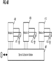
- FIG. 4B a simplified sensor arrangement for Site 2 is shown having a plurality of sensors that are coupled ("D") to the computing device 401 of FIG. 4A under an illustrative embodiment.
- the sensor arrangement is configured as one or more sensor devices and/or smart sensor modules arranged for calibration in a manufacturing setup.
- Each of the sensor devices and/or smart sensor modules may include sensor elements (SE) 411-413 and calibration modules 408-410 arranged as two portions together with device calibration station 407.
- SE sensor elements
- calibration modules 408-410 arranged as two portions together with device calibration station 407.
- each SE (411-413) and respective calibration module (409-410) may be integrated together as a single unit.
- the sensor arrangement of FIG. 4B may have the same platform as the sensor arrangement of FIG. 1B , but may include different sensors or sensors having different sensor calibration parameter requirements.
- the sensor system may be configured to service both sites individually and/or simultaneously.
- sensor calibration parameter sets from database 110A may be communicated ("B") to Site 1 (Device 101), while sensor calibration parameter sets from database 111B may be communicated ("C") to Site 2 (Device 401).
- each site may recursively calibrate sensor arrangements (e.g., FIG. 1B , FIG. 4B ) as described in FIG. 3 .
- Sensor calibration output data may similarly be received from each site (Site 1, Site 2) and stored in a respective database (110A, 111B) as illustrated in Fig. 4C .
- the present disclosure provides effective and efficient sensor device-level calibration for various end user applications events, such that the scalability can be implemented as a manufacturing-centric process as well as a service-oriented product solution.
- Advantages of the present disclosure may include the system configuration for scalable techniques for implementing a generic service platform for calibrating various sensor front end circuits at the time of manufacturing, such as by fetching current or updated optimized sensor calibration parameters from secure cloud storage. Further advantages may include operating the system in tandem with each individualized sensor updated parameter information that may be accumulated back into the cloud. Additionally, data can be managed through post-manufacturing data analytics programs to analyze, compare, and optimize calibration parameter settings from multiple manufacturing sites, and for updating these same devices once commercially available in the field.
- the present disclosure also provides the ability to store large amounts of different calibration parameter settings in secure cloud storage as an extension to conventional non-volatile memory components such as a EEPROM.
- system calibration operations programming sequence managed from a calibration system computer selected sets of predefined sensor calibration parameters can be fetched from the secure cloud storage and loaded into the calibration system computer's local memory (e.g., during a production phase).
- the predefined accelerometer calibration parameters which may include calibration coefficients and configuration information, may be fetched from the secure cloud storage and loaded into the calibration system computer's local memory to be managed by the system calibration operations programming sequence.
- the same or site-specific predefined sensor calibration parameter settings may be fetched from cloud storage and loaded into the manufacturing sensor calibration system computers located at different production sites.
- the actual system calibration operations programming sequence may manage sensor calibrations for each device in production.
- the present disclosure also bridges the gap between individual sensor device level calibration from the component provider (which mainly focuses on sensor device design circuit level intrinsic effects), and the end user sensor calibrations for various applications events.
- a motion sensor that combines an accelerometer with a gyroscope or magnetometer may be re-calibrated, based on environmental factors or geographic location information. The re-calibrated data may then be fed back to the cloud and subjected to data analytics to become part of new calibration parameter settings.
- the cloud storage based sensor calibration parameter settings may allow the sensor manufacturing process to program either the initial sensor design-related calibration parameter settings at the circuit level, or use modified settings based on analytics outputs that integrate end-user application-related criteria to provide optimized settings for various user applications events.
- different manufacturing process-related variations e.g., long time drift effects, recent sensor manufacturer enhancements
Landscapes
- Physics & Mathematics (AREA)
- General Physics & Mathematics (AREA)
- Engineering & Computer Science (AREA)
- Computer Networks & Wireless Communication (AREA)
- Signal Processing (AREA)
- Testing Or Calibration Of Command Recording Devices (AREA)
- Health & Medical Sciences (AREA)
- Computing Systems (AREA)
- General Health & Medical Sciences (AREA)
- Medical Informatics (AREA)
Claims (15)
- Ein Computersystem zur Kalibrierung eines oder mehrerer Sensoren (110, 111, 112), aufweisend:einen Prozessor (106);eine Kommunikationsschnittstelle (102), die mit dem Prozessor (106) operativ gekoppelt ist, wobei die Kommunikationsschnittstelle (102) konfiguriert ist, um über ein Rechnernetz einen Kalibrierungsparametersatz zu empfangen;eine Vielzahl von Kalibrierungssystem-Busschnittstellen (103), die mit dem Prozessor (106) operativ gekoppelt sind, um mit einer Vielzahl von Kalibrierungsmodulen (107, 108, 109) entsprechend jedem des einen oder der mehreren Sensoren (110, 111, 112) zu kommunizieren,wobei jede der Kalibrierungssystem-Busschnittstellen (103) den empfangenen Kalibrierungsparametersatz zu einem besonderen der Vielzahl der Kalibrierungsmodule (107, 108, 109) des einen oder der mehreren Sensoren (110, 111, 112) überträgt,wobei jede der Kalibrierungssystem-Busschnittstellen (103) in Reaktion auf den übertragenen Kalibrierungsparametersatz Kalibrierungsausgangsdaten vom jeweiligen einen oder den jeweiligen mehreren Sensoren (110, 111, 112) entsprechend dem besonderen Kalibrierungsmodul empfängt, undwobei die Kommunikationsschnittstelle (102) die Kalibrierungsausgangsdaten zum Rechnernetz überträgt, wodurch ein neuer Kalibrierungsparametersatz erzeugt wird.
- Das Computersystem nach Anspruch 1, wobei die Kalibrierungsausgangsdaten von den Sensoren analoge Front-End-Verstärkungsdaten und Versatzwertdaten aufweisen.
- Das Computersystem nach Anspruch 2, wobei die Kalibrierungsdatenausgangsdaten Kalibrierungskoeffizientwertdaten aufweisen.
- Das Computersystem nach Anspruch 3, wobei die Kalibrierungskoeffizientwertdaten zumindest eine von analogen programmierbaren Verstärkungskoeffizienteneinstellungen, Analogfilterkoeffizienteneinstellungen, Digitalfilterkoeffizienteneinstellungen, Koeffizienteneinstellungen zur algorithmischen Implementation eines digitalen Signalprozessors (DSP), mit dem Sensorherstellungsprozess korrelierten Koeffizienteneinstellungen, mit Sensorendverbraucherereignissen korrelierten Koeffizienteneinstellungen, von der Sensorvorrichtungstemperatur abhängigen analytischen Koeffizienteneinstellungen, von der Sensorvorrichtungsspannung abhängigen analytischen Koeffizienteneinstellungen, vom Sensorvorrichtungsprozess abhängigen analytischen Koeffizienteneinstellungen, mit einer Sensorfusionsimplementation korrelierten Koeffizienteneinstellungen, mit einer Sensormodulherstellungsprozessphase korrelierten Koeffizienteneinstellungen und mit Sensormodulherstellungs-Endverbraucherereignissen korrelierten Koeffizienteneinstellungen aufweisen.
- Das Computersystem nach Anspruch 1, wobei die Kalibrierungsausgangsdaten einen Sensorbetrieb basierend auf zumindest einem eines kleinsten Erfassungswerts und eines größten Erfassungswerts basierend auf dem Kalibrierungsparametersatz aufweisen, oder
wobei die Kalibrierungsausgangsdaten einen Sensorbetrieb basierend auf einer Vielzahl vorbestimmter Erfassungswerte basierend auf dem Kalibrierungsparametersatz aufweisen, und/oder wobei die Kalibrierungssystem-Busschnittstelle (103) eine einer Inter-IC-Bus (I2C)-Schnittstelle, einer Serial Peripheral Interface (SPI), einer IEEE 1461-Schnittstelle und einer universellen Mikrosensor-Schnittstelle (UMSI) aufweist. - Ein Verfahren zur Kalibrierung eines oder mehrerer Sensoren (110, 111, 112) in einem System, aufweisend:Empfangen eines Kalibrierungsparametersatzes für den einen oder die mehreren Sensoren (110, 111, 112) von einem Rechnernetz;Liefern des empfangenen Kalibrierungsparametersatzes zu einem besonderen einer Vielzahl von Kalibrierungsmodulen (107, 108, 109) entsprechend jedem des einen oder der mehreren Sensoren (110, 111, 112) unter Verwendung einer einer Vielzahl von Kalibrierungssystem-Busschnittstellen (103);Erzeugen von Kalibrierungsausgangsdaten vom jeweiligen einen oder den jeweiligen mehreren Sensoren (110, 111, 112) entsprechend dem besonderen Kalibrierungsmodul in Reaktion auf den Kalibrierungsparametersatz;Übertragen der Kalibrierungsausgangsdaten zum Rechnernetz; undEmpfangen eines neuen Kalibrierungsparametersatzes für die Vielzahl der Kalibrierungsmodule (107, 108, 109) des einen oder der mehreren Sensoren (110, 111, 112) in Reaktion auf die Kalibrierungsausgangsdaten.
- Das Verfahren nach Anspruch 6, wobei die Kalibrierungsausgangsdaten von den Sensoren analoge Front-End-Verstärkungsdaten und Versatzwertdaten aufweisen.
- Das Verfahren nach Anspruch 7, wobei die Kalibrierungsdatenausgangsdaten Kalibrierungskoeffizientwertdaten aufweisen.
- Das Verfahren nach Anspruch 8, wobei die Kalibrierungskoeffizientwertdaten zumindest eine von analogen programmierbaren Verstärkungskoeffizienteneinstellungen, Analogfilterkoeffizienteneinstellungen, Digitalfilterkoeffizienteneinstellungen, Koeffizienteneinstellungen zur algorithmischen Implementation eines digitalen Signalprozessors (DSP), mit dem Sensorherstellungsprozess korrelierten Koeffizienteneinstellungen, mit Sensorendverbraucherereignissen korrelierten Koeffizienteneinstellungen, von der Sensorvorrichtungstemperatur abhängigen analytischen Koeffizienteneinstellungen, von der Sensorvorrichtungsspannung abhängigen analytischen Koeffizienteneinstellungen, vom Sensorvorrichtungsprozess abhängigen analytischen Koeffizienteneinstellungen, mit einer Sensorfusionsimplementation korrelierten Koeffizienteneinstellungen, mit einer Sensormodulherstellungsprozessphase korrelierten Koeffizienteneinstellungen und mit Sensormodulherstellungs-Endverbraucherereignissen korrelierten Koeffizienteneinstellungen aufweisen.
- Das Verfahren nach Anspruch 6, wobei die Kalibrierungsausgangsdaten einen Sensorbetrieb basierend auf zumindest einem eines kleinsten Erfassungswerts und eines größten Erfassungswerts basierend auf dem Kalibrierungsparametersatz aufweisen, oder
wobei die Kalibrierungsausgangsdaten einen Sensorbetrieb basierend auf einer Vielzahl vorbestimmter Erfassungswerte basierend auf dem Kalibrierungsparametersatz aufweisen, und/oder
wobei das Übertragen des empfangenen Kalibrierungsparametersatzes Übertragen unter Verwendung einer einer Inter-IC-Bus (I2C)-Schnittstelle, einer Serial Peripheral Interface (SPI), einer IEEE 1461-Schnittstelle und einer universellen Mikrosensor-Schnittstelle (UMSI) aufweist. - Ein Verfahren zur Kalibrierung eines oder mehrerer Sensoren (110, 111, 112) in einem System, aufweisend:Empfangen einer Vielzahl von Kalibrierungsparametersätzen für eine Vielzahl von Kalibrierungsmodulen (107, 108, 109) entsprechend jedem einer Vielzahl von Sensoren (110, 111, 112) von einem Rechnernetz;nacheinander erfolgendes Übertragen jedes der empfangenen Kalibrierungsparametersätze zu zumindest einem einer Vielzahl von Kalibrierungsmodulen (107, 108, 109) jedes der Vielzahl der Sensoren (110, 111, 112) unter Verwendung einer Vielzahl von Kalibrierungssystem-Busschnittstellen (103);nacheinander erfolgendes Empfangen und Speichern von Kalibrierungsausgangsdaten von jedem der jeweiligen Sensoren (110, 111, 112) entsprechend dem zumindest einen der ausgewählten Kalibrierungsmodule in Reaktion auf jeden übertragenen Kalibrierungsparametersatz;Übertragen der Kalibrierungsausgangsdaten zum Rechnernetz; undEmpfangen eines neuen Kalibrierungsparametersatzes für die Vielzahl der Kalibrierungsmodule (107, 108, 109) entsprechend dem einen oder den mehreren Sensoren (110, 111, 112) in Reaktion auf die Kalibrierungsausgangsdaten.
- Das Verfahren nach Anspruch 11, wobei die Kalibrierungsausgangsdaten von den Sensoren analoge Front-End-Verstärkungsdaten und Versatzwertdaten aufweisen.
- Das Verfahren nach Anspruch 12, wobei die Kalibrierungsdatenausgangsdaten Kalibrierungskoeffizientwertdaten aufweisen.
- Das Verfahren nach Anspruch 13, wobei die Kalibrierungskoeffizientwertdaten zumindest eine von analogen programmierbaren Verstärkungskoeffizienteneinstellungen, Analogfilterkoeffizienteneinstellungen, Digitalfilterkoeffizienteneinstellungen, Koeffizienteneinstellungen zur algorithmischen Implementation eines digitalen Signalprozessors (DSP), mit dem Sensorherstellungsprozess korrelierten Koeffizienteneinstellungen, mit Sensorendverbraucherereignissen korrelierten Koeffizienteneinstellungen, von der Sensorvorrichtungstemperatur abhängigen analytischen Koeffizienteneinstellungen, von der Sensorvorrichtungsspannung abhängigen analytischen Koeffizienteneinstellungen, vom Sensorvorrichtungsprozess abhängigen analytischen Koeffizienteneinstellungen, mit einer Sensorfusionsimplementation korrelierten Koeffizienteneinstellungen, mit einer Sensormodulherstellungsprozessphase korrelierten Koeffizienteneinstellungen und mit Sensormodulherstellungs-Endverbraucherereignissen korrelierten Koeffizienteneinstellungen aufweisen.
- Das Verfahren nach Anspruch 11, wobei die Kalibrierungsausgangsdaten einen Sensorbetrieb basierend auf zumindest einem eines kleinsten Erfassungswerts und eines größten Erfassungswerts basierend auf dem Kalibrierungsparametersatz aufweisen, oder
wobei die Kalibrierungsausgangsdaten einen Sensorbetrieb basierend auf einer Vielzahl vorbestimmter Erfassungswerte basierend auf dem Kalibrierungsparametersatz aufweisen.
Applications Claiming Priority (2)
| Application Number | Priority Date | Filing Date | Title |
|---|---|---|---|
| US14/946,121 US10551226B2 (en) | 2015-11-19 | 2015-11-19 | System and method for scalable cloud-based sensor calibration |
| PCT/US2016/063108 WO2017087953A1 (en) | 2015-11-19 | 2016-11-21 | System and method for scalable cloud-based sensor calibration |
Publications (3)
| Publication Number | Publication Date |
|---|---|
| EP3377979A1 EP3377979A1 (de) | 2018-09-26 |
| EP3377979A4 EP3377979A4 (de) | 2018-12-12 |
| EP3377979B1 true EP3377979B1 (de) | 2020-10-14 |
Family
ID=58717969
Family Applications (1)
| Application Number | Title | Priority Date | Filing Date |
|---|---|---|---|
| EP16867335.8A Active EP3377979B1 (de) | 2015-11-19 | 2016-11-21 | System und verfahren zur skalierbaren cloudbasierten sensorkalibrierung |
Country Status (4)
| Country | Link |
|---|---|
| US (1) | US10551226B2 (de) |
| EP (1) | EP3377979B1 (de) |
| CN (1) | CN108292285B (de) |
| WO (1) | WO2017087953A1 (de) |
Families Citing this family (17)
| Publication number | Priority date | Publication date | Assignee | Title |
|---|---|---|---|---|
| US10037300B2 (en) * | 2016-08-23 | 2018-07-31 | Origin Gps Ltd. | Cloud programming sensor interface architecture |
| EP3425324B2 (de) * | 2017-07-04 | 2022-11-16 | Sick Ag | Verfahren zur parametrierung eines sensors |
| DE102018214156A1 (de) * | 2018-08-22 | 2020-02-27 | Robert Bosch Gmbh | Verfahren zur Kalibrierung eines Sensors eines Geräts und Sensorsystem |
| WO2020150971A1 (en) * | 2019-01-24 | 2020-07-30 | Siemens Aktiengesellschaft | Extension module for independently storing calibration data, component, and component calibration method |
| EP3751532B1 (de) * | 2019-06-13 | 2025-07-30 | Rohde & Schwarz GmbH & Co. KG | Fernzugriffs- und -steuerungssystem und entsprechendes verfahren |
| US20210243081A1 (en) * | 2020-02-05 | 2021-08-05 | Machinesense, Llc | SYSTEMS AND METHODS FOR CALIBRATING SENSORS OF INTERNET OF THINGS (IoT) SYSTEMS |
| US12085468B2 (en) * | 2020-08-17 | 2024-09-10 | Fluke Corporation | Method and system for universal calibration of devices under test |
| CN111982194B (zh) * | 2020-08-18 | 2023-03-28 | 成都一通密封股份有限公司 | 一种无线压力温度一体化传感器 |
| US11387838B1 (en) | 2021-03-19 | 2022-07-12 | Microsoft Technology Licensing, Llc | SAR analog-to-digital converter calibration |
| US11677409B2 (en) * | 2021-03-19 | 2023-06-13 | Microsoft Technology Licensing, Llc | Cloud assisted calibration of analog-to-digital converters |
| CN113447064B (zh) * | 2021-06-30 | 2024-10-18 | 东莞市小精灵教育软件有限公司 | 一种校准方法和电子设备 |
| CN114323104A (zh) * | 2021-12-23 | 2022-04-12 | 沈阳环境科学研究院 | 一种车辆环境检测传感器在线校准系统 |
| KR20230111137A (ko) * | 2022-01-17 | 2023-07-25 | 현대자동차주식회사 | M2m 시스템에서 클라우드 기반 센서 캘리브레이션 방법 및 장치 |
| US12452254B2 (en) * | 2022-03-29 | 2025-10-21 | Toyota Motor North America, Inc. | Secure signed file upload |
| CN116380146A (zh) * | 2023-03-23 | 2023-07-04 | 成都飞机工业(集团)有限责任公司 | 一种试飞测试传感器标定方法、装置、设备及介质 |
| CN116595416B (zh) * | 2023-05-17 | 2026-02-10 | 苏州德姆斯信息技术有限公司 | 多类型数据采集方法、系统、终端及存储介质 |
| CN117190997B (zh) * | 2023-11-06 | 2024-01-05 | 四川图林科技有限责任公司 | 一种半球谐振陀螺仪的正交误差控制方法 |
Family Cites Families (22)
| Publication number | Priority date | Publication date | Assignee | Title |
|---|---|---|---|---|
| US20060243839A9 (en) * | 2000-03-08 | 2006-11-02 | Metso Minerals (Tampere) Oy | Method and apparatus for measuring and adjusting the setting of a crusher |
| US7269527B1 (en) * | 2006-01-17 | 2007-09-11 | Innovative American Technology, Inc. | System integration module for CBRNE sensors |
| US20040139110A1 (en) * | 2002-12-31 | 2004-07-15 | Lamarca Anthony G. | Sensor network control and calibration system |
| US7920906B2 (en) * | 2005-03-10 | 2011-04-05 | Dexcom, Inc. | System and methods for processing analyte sensor data for sensor calibration |
| US7190178B2 (en) * | 2004-05-13 | 2007-03-13 | Ami Semiconductor, Inc. | Pade′ Approximant based compensation for integrated sensor modules and the like |
| US20060213249A1 (en) * | 2005-03-28 | 2006-09-28 | Medrad, Inc. | Devices, systems and method for calibration of systems |
| US8077205B2 (en) | 2007-06-14 | 2011-12-13 | Sony Corporation | Adaptive prediction of calibration parameters for color imaging devices |
| US9104430B2 (en) | 2008-02-11 | 2015-08-11 | Palo Alto Research Center Incorporated | System and method for enabling extensibility in sensing systems |
| JP5570775B2 (ja) * | 2008-09-26 | 2014-08-13 | 株式会社日立国際電気 | 基板処理装置のセットアップ方法、基板処理装置により実施される半導体装置の製造方法及び基板処理装置 |
| US8447249B1 (en) * | 2010-06-16 | 2013-05-21 | Qualcomm Incorporated | System and method for providing open loop transmit power control |
| US20120173185A1 (en) * | 2010-12-30 | 2012-07-05 | Caterpillar Inc. | Systems and methods for evaluating range sensor calibration data |
| US9720406B2 (en) * | 2011-08-15 | 2017-08-01 | Endress+Hauser Conducta Gmbh+Co. Kg | Measuring system |
| US9534924B2 (en) * | 2011-11-11 | 2017-01-03 | Qualcomm Incorporated | Sensor auto-calibration |
| EP2776788B1 (de) * | 2011-11-11 | 2019-11-27 | Sony Mobile Communications AB | System und verfahren zur unterstützten eichung von auf verschiedene geräte verteilten sensoren |
| US9625490B2 (en) * | 2011-12-01 | 2017-04-18 | Qualcomm Incorporated | Mitigating the effect of a change in sensor calibration parameters |
| WO2013104006A2 (en) * | 2012-01-08 | 2013-07-11 | Sensor Platforms, Inc. | System and method for calibrating sensors for different operating environments |
| CN103699058B (zh) * | 2012-05-24 | 2017-08-25 | 株式会社堀场制作所 | 测试系统及设备管理装置 |
| US9291608B2 (en) | 2013-03-13 | 2016-03-22 | Aclima Inc. | Calibration method for distributed sensor system |
| CN103337066B (zh) * | 2013-05-27 | 2016-05-18 | 清华大学 | 3d获取系统的校准方法 |
| US20160187368A1 (en) * | 2014-12-30 | 2016-06-30 | Google Inc. | Systems and methods of detecting failure of an opening sensor |
| DE102015109009B4 (de) * | 2015-06-08 | 2025-10-30 | Infineon Technologies Ag | Stromsensorchip mit Magnetfeldsensor |
| US10543314B2 (en) * | 2015-08-21 | 2020-01-28 | Medtronic Minimed, Inc. | Personalized parameter modeling with signal calibration based on historical data |
-
2015
- 2015-11-19 US US14/946,121 patent/US10551226B2/en active Active
-
2016
- 2016-11-21 CN CN201680068058.7A patent/CN108292285B/zh active Active
- 2016-11-21 WO PCT/US2016/063108 patent/WO2017087953A1/en not_active Ceased
- 2016-11-21 EP EP16867335.8A patent/EP3377979B1/de active Active
Non-Patent Citations (1)
| Title |
|---|
| None * |
Also Published As
| Publication number | Publication date |
|---|---|
| CN108292285B (zh) | 2022-04-15 |
| EP3377979A4 (de) | 2018-12-12 |
| CN108292285A (zh) | 2018-07-17 |
| EP3377979A1 (de) | 2018-09-26 |
| WO2017087953A1 (en) | 2017-05-26 |
| US10551226B2 (en) | 2020-02-04 |
| US20170146375A1 (en) | 2017-05-25 |
Similar Documents
| Publication | Publication Date | Title |
|---|---|---|
| EP3377979B1 (de) | System und verfahren zur skalierbaren cloudbasierten sensorkalibrierung | |
| JP6072112B2 (ja) | センサシステム | |
| KR101423964B1 (ko) | 분광계의 광 신호 처리 방법 및 그 장치 | |
| JP7032339B2 (ja) | 測定システム | |
| CN110617916A (zh) | 一种气压传感器的校准方法及装置 | |
| US7979227B2 (en) | Calibration in a laboratory reference method | |
| CA2831443C (en) | System and method for producing statistically valid assay means and ranges for quality control materials | |
| Klaus et al. | Calibration of bridge-, charge-and voltage amplifiers for dynamic measurement applications | |
| US10067105B2 (en) | Method for operating a measuring site | |
| EP3420329A1 (de) | Digitale kriech- und driftkorrektur | |
| RU2571445C2 (ru) | Способ коррекции измерения напряжения на контактах датчика | |
| CN101593151A (zh) | 用于实时计算过程模型状态量的方法和模拟器 | |
| CN102928014B (zh) | 电力系统数字测量或遥测处理的方法及装置 | |
| Mende et al. | Sensors with digital output–a metrological challenge | |
| Dickow et al. | A systematic MEMS sensor calibration framework | |
| US6757641B1 (en) | Multi sensor transducer and weight factor | |
| CN116539076A (zh) | 在生产过程期间校准电子组件 | |
| CN116576904B (zh) | 传感器测试方法及装置、电子设备及计算机可读存储介质 | |
| US20080065942A1 (en) | Synthetic instrument utilizing peer-to-peer communication for error correction | |
| EP3637565B1 (de) | Maser-umweltanalysesystem | |
| CN114705231B (zh) | 一种提高光纤光栅解算一致性的方法 | |
| US12618697B2 (en) | Method for diagnosing a sensor system in a part-specific manner | |
| CN111795715A (zh) | 校正分析传感器测量数据的方法和校正测量数据的传感器 | |
| US20220276079A1 (en) | Method for diagnosing a sensor system in a part-specific manner | |
| Walendziuk et al. | Development of a Wireless Weighing Transducer and its Calibration |
Legal Events
| Date | Code | Title | Description |
|---|---|---|---|
| STAA | Information on the status of an ep patent application or granted ep patent |
Free format text: STATUS: THE INTERNATIONAL PUBLICATION HAS BEEN MADE |
|
| PUAI | Public reference made under article 153(3) epc to a published international application that has entered the european phase |
Free format text: ORIGINAL CODE: 0009012 |
|
| STAA | Information on the status of an ep patent application or granted ep patent |
Free format text: STATUS: REQUEST FOR EXAMINATION WAS MADE |
|
| 17P | Request for examination filed |
Effective date: 20180618 |
|
| AK | Designated contracting states |
Kind code of ref document: A1 Designated state(s): AL AT BE BG CH CY CZ DE DK EE ES FI FR GB GR HR HU IE IS IT LI LT LU LV MC MK MT NL NO PL PT RO RS SE SI SK SM TR |
|
| AX | Request for extension of the european patent |
Extension state: BA ME |
|
| A4 | Supplementary search report drawn up and despatched |
Effective date: 20181109 |
|
| RIC1 | Information provided on ipc code assigned before grant |
Ipc: G06F 13/38 20060101AFI20181105BHEP Ipc: G01D 18/00 20060101ALI20181105BHEP |
|
| DAV | Request for validation of the european patent (deleted) | ||
| DAX | Request for extension of the european patent (deleted) | ||
| STAA | Information on the status of an ep patent application or granted ep patent |
Free format text: STATUS: EXAMINATION IS IN PROGRESS |
|
| 17Q | First examination report despatched |
Effective date: 20191031 |
|
| GRAP | Despatch of communication of intention to grant a patent |
Free format text: ORIGINAL CODE: EPIDOSNIGR1 |
|
| STAA | Information on the status of an ep patent application or granted ep patent |
Free format text: STATUS: GRANT OF PATENT IS INTENDED |
|
| INTG | Intention to grant announced |
Effective date: 20200508 |
|
| RIN1 | Information on inventor provided before grant (corrected) |
Inventor name: SUAREZ, GUSTAVO ARMANDO Inventor name: LUO, YONG |
|
| GRAS | Grant fee paid |
Free format text: ORIGINAL CODE: EPIDOSNIGR3 |
|
| GRAA | (expected) grant |
Free format text: ORIGINAL CODE: 0009210 |
|
| STAA | Information on the status of an ep patent application or granted ep patent |
Free format text: STATUS: THE PATENT HAS BEEN GRANTED |
|
| AK | Designated contracting states |
Kind code of ref document: B1 Designated state(s): AL AT BE BG CH CY CZ DE DK EE ES FI FR GB GR HR HU IE IS IT LI LT LU LV MC MK MT NL NO PL PT RO RS SE SI SK SM TR |
|
| REG | Reference to a national code |
Ref country code: GB Ref legal event code: FG4D |
|
| REG | Reference to a national code |
Ref country code: AT Ref legal event code: REF Ref document number: 1324262 Country of ref document: AT Kind code of ref document: T Effective date: 20201015 Ref country code: CH Ref legal event code: EP |
|
| REG | Reference to a national code |
Ref country code: DE Ref legal event code: R096 Ref document number: 602016046020 Country of ref document: DE |
|
| REG | Reference to a national code |
Ref country code: IE Ref legal event code: FG4D |
|
| REG | Reference to a national code |
Ref country code: AT Ref legal event code: MK05 Ref document number: 1324262 Country of ref document: AT Kind code of ref document: T Effective date: 20201014 |
|
| REG | Reference to a national code |
Ref country code: NL Ref legal event code: MP Effective date: 20201014 |
|
| PG25 | Lapsed in a contracting state [announced via postgrant information from national office to epo] |
Ref country code: GR Free format text: LAPSE BECAUSE OF FAILURE TO SUBMIT A TRANSLATION OF THE DESCRIPTION OR TO PAY THE FEE WITHIN THE PRESCRIBED TIME-LIMIT Effective date: 20210115 Ref country code: FI Free format text: LAPSE BECAUSE OF FAILURE TO SUBMIT A TRANSLATION OF THE DESCRIPTION OR TO PAY THE FEE WITHIN THE PRESCRIBED TIME-LIMIT Effective date: 20201014 Ref country code: NO Free format text: LAPSE BECAUSE OF FAILURE TO SUBMIT A TRANSLATION OF THE DESCRIPTION OR TO PAY THE FEE WITHIN THE PRESCRIBED TIME-LIMIT Effective date: 20210114 Ref country code: RS Free format text: LAPSE BECAUSE OF FAILURE TO SUBMIT A TRANSLATION OF THE DESCRIPTION OR TO PAY THE FEE WITHIN THE PRESCRIBED TIME-LIMIT Effective date: 20201014 Ref country code: PT Free format text: LAPSE BECAUSE OF FAILURE TO SUBMIT A TRANSLATION OF THE DESCRIPTION OR TO PAY THE FEE WITHIN THE PRESCRIBED TIME-LIMIT Effective date: 20210215 |
|
| REG | Reference to a national code |
Ref country code: LT Ref legal event code: MG4D |
|
| PG25 | Lapsed in a contracting state [announced via postgrant information from national office to epo] |
Ref country code: SE Free format text: LAPSE BECAUSE OF FAILURE TO SUBMIT A TRANSLATION OF THE DESCRIPTION OR TO PAY THE FEE WITHIN THE PRESCRIBED TIME-LIMIT Effective date: 20201014 Ref country code: LV Free format text: LAPSE BECAUSE OF FAILURE TO SUBMIT A TRANSLATION OF THE DESCRIPTION OR TO PAY THE FEE WITHIN THE PRESCRIBED TIME-LIMIT Effective date: 20201014 Ref country code: IS Free format text: LAPSE BECAUSE OF FAILURE TO SUBMIT A TRANSLATION OF THE DESCRIPTION OR TO PAY THE FEE WITHIN THE PRESCRIBED TIME-LIMIT Effective date: 20210214 Ref country code: PL Free format text: LAPSE BECAUSE OF FAILURE TO SUBMIT A TRANSLATION OF THE DESCRIPTION OR TO PAY THE FEE WITHIN THE PRESCRIBED TIME-LIMIT Effective date: 20201014 Ref country code: BG Free format text: LAPSE BECAUSE OF FAILURE TO SUBMIT A TRANSLATION OF THE DESCRIPTION OR TO PAY THE FEE WITHIN THE PRESCRIBED TIME-LIMIT Effective date: 20210114 Ref country code: ES Free format text: LAPSE BECAUSE OF FAILURE TO SUBMIT A TRANSLATION OF THE DESCRIPTION OR TO PAY THE FEE WITHIN THE PRESCRIBED TIME-LIMIT Effective date: 20201014 Ref country code: AT Free format text: LAPSE BECAUSE OF FAILURE TO SUBMIT A TRANSLATION OF THE DESCRIPTION OR TO PAY THE FEE WITHIN THE PRESCRIBED TIME-LIMIT Effective date: 20201014 |
|
| PG25 | Lapsed in a contracting state [announced via postgrant information from national office to epo] |
Ref country code: NL Free format text: LAPSE BECAUSE OF FAILURE TO SUBMIT A TRANSLATION OF THE DESCRIPTION OR TO PAY THE FEE WITHIN THE PRESCRIBED TIME-LIMIT Effective date: 20201014 Ref country code: HR Free format text: LAPSE BECAUSE OF FAILURE TO SUBMIT A TRANSLATION OF THE DESCRIPTION OR TO PAY THE FEE WITHIN THE PRESCRIBED TIME-LIMIT Effective date: 20201014 |
|
| REG | Reference to a national code |
Ref country code: CH Ref legal event code: PL |
|
| REG | Reference to a national code |
Ref country code: DE Ref legal event code: R097 Ref document number: 602016046020 Country of ref document: DE |
|
| PG25 | Lapsed in a contracting state [announced via postgrant information from national office to epo] |
Ref country code: RO Free format text: LAPSE BECAUSE OF FAILURE TO SUBMIT A TRANSLATION OF THE DESCRIPTION OR TO PAY THE FEE WITHIN THE PRESCRIBED TIME-LIMIT Effective date: 20201014 Ref country code: SK Free format text: LAPSE BECAUSE OF FAILURE TO SUBMIT A TRANSLATION OF THE DESCRIPTION OR TO PAY THE FEE WITHIN THE PRESCRIBED TIME-LIMIT Effective date: 20201014 Ref country code: CZ Free format text: LAPSE BECAUSE OF FAILURE TO SUBMIT A TRANSLATION OF THE DESCRIPTION OR TO PAY THE FEE WITHIN THE PRESCRIBED TIME-LIMIT Effective date: 20201014 Ref country code: EE Free format text: LAPSE BECAUSE OF FAILURE TO SUBMIT A TRANSLATION OF THE DESCRIPTION OR TO PAY THE FEE WITHIN THE PRESCRIBED TIME-LIMIT Effective date: 20201014 Ref country code: SM Free format text: LAPSE BECAUSE OF FAILURE TO SUBMIT A TRANSLATION OF THE DESCRIPTION OR TO PAY THE FEE WITHIN THE PRESCRIBED TIME-LIMIT Effective date: 20201014 Ref country code: LT Free format text: LAPSE BECAUSE OF FAILURE TO SUBMIT A TRANSLATION OF THE DESCRIPTION OR TO PAY THE FEE WITHIN THE PRESCRIBED TIME-LIMIT Effective date: 20201014 Ref country code: LU Free format text: LAPSE BECAUSE OF NON-PAYMENT OF DUE FEES Effective date: 20201121 Ref country code: MC Free format text: LAPSE BECAUSE OF FAILURE TO SUBMIT A TRANSLATION OF THE DESCRIPTION OR TO PAY THE FEE WITHIN THE PRESCRIBED TIME-LIMIT Effective date: 20201014 |
|
| REG | Reference to a national code |
Ref country code: BE Ref legal event code: MM Effective date: 20201130 |
|
| PLBE | No opposition filed within time limit |
Free format text: ORIGINAL CODE: 0009261 |
|
| STAA | Information on the status of an ep patent application or granted ep patent |
Free format text: STATUS: NO OPPOSITION FILED WITHIN TIME LIMIT |
|
| PG25 | Lapsed in a contracting state [announced via postgrant information from national office to epo] |
Ref country code: CH Free format text: LAPSE BECAUSE OF NON-PAYMENT OF DUE FEES Effective date: 20201130 Ref country code: DK Free format text: LAPSE BECAUSE OF FAILURE TO SUBMIT A TRANSLATION OF THE DESCRIPTION OR TO PAY THE FEE WITHIN THE PRESCRIBED TIME-LIMIT Effective date: 20201014 Ref country code: LI Free format text: LAPSE BECAUSE OF NON-PAYMENT OF DUE FEES Effective date: 20201130 |
|
| 26N | No opposition filed |
Effective date: 20210715 |
|
| GBPC | Gb: european patent ceased through non-payment of renewal fee |
Effective date: 20210114 |
|
| PG25 | Lapsed in a contracting state [announced via postgrant information from national office to epo] |
Ref country code: IE Free format text: LAPSE BECAUSE OF NON-PAYMENT OF DUE FEES Effective date: 20201121 Ref country code: AL Free format text: LAPSE BECAUSE OF FAILURE TO SUBMIT A TRANSLATION OF THE DESCRIPTION OR TO PAY THE FEE WITHIN THE PRESCRIBED TIME-LIMIT Effective date: 20201014 Ref country code: FR Free format text: LAPSE BECAUSE OF NON-PAYMENT OF DUE FEES Effective date: 20201214 Ref country code: IT Free format text: LAPSE BECAUSE OF FAILURE TO SUBMIT A TRANSLATION OF THE DESCRIPTION OR TO PAY THE FEE WITHIN THE PRESCRIBED TIME-LIMIT Effective date: 20201014 |
|
| PG25 | Lapsed in a contracting state [announced via postgrant information from national office to epo] |
Ref country code: GB Free format text: LAPSE BECAUSE OF NON-PAYMENT OF DUE FEES Effective date: 20210114 Ref country code: SI Free format text: LAPSE BECAUSE OF FAILURE TO SUBMIT A TRANSLATION OF THE DESCRIPTION OR TO PAY THE FEE WITHIN THE PRESCRIBED TIME-LIMIT Effective date: 20201014 |
|
| PG25 | Lapsed in a contracting state [announced via postgrant information from national office to epo] |
Ref country code: IS Free format text: LAPSE BECAUSE OF FAILURE TO SUBMIT A TRANSLATION OF THE DESCRIPTION OR TO PAY THE FEE WITHIN THE PRESCRIBED TIME-LIMIT Effective date: 20210214 Ref country code: TR Free format text: LAPSE BECAUSE OF FAILURE TO SUBMIT A TRANSLATION OF THE DESCRIPTION OR TO PAY THE FEE WITHIN THE PRESCRIBED TIME-LIMIT Effective date: 20201014 Ref country code: MT Free format text: LAPSE BECAUSE OF FAILURE TO SUBMIT A TRANSLATION OF THE DESCRIPTION OR TO PAY THE FEE WITHIN THE PRESCRIBED TIME-LIMIT Effective date: 20201014 Ref country code: CY Free format text: LAPSE BECAUSE OF FAILURE TO SUBMIT A TRANSLATION OF THE DESCRIPTION OR TO PAY THE FEE WITHIN THE PRESCRIBED TIME-LIMIT Effective date: 20201014 |
|
| PG25 | Lapsed in a contracting state [announced via postgrant information from national office to epo] |
Ref country code: MK Free format text: LAPSE BECAUSE OF FAILURE TO SUBMIT A TRANSLATION OF THE DESCRIPTION OR TO PAY THE FEE WITHIN THE PRESCRIBED TIME-LIMIT Effective date: 20201014 |
|
| PG25 | Lapsed in a contracting state [announced via postgrant information from national office to epo] |
Ref country code: BE Free format text: LAPSE BECAUSE OF NON-PAYMENT OF DUE FEES Effective date: 20201130 |
|
| P01 | Opt-out of the competence of the unified patent court (upc) registered |
Effective date: 20230524 |
|
| PGFP | Annual fee paid to national office [announced via postgrant information from national office to epo] |
Ref country code: DE Payment date: 20251118 Year of fee payment: 10 |