EP3377794B1 - Holding back elongate elements during subsea operations - Google Patents
Holding back elongate elements during subsea operations Download PDFInfo
- Publication number
- EP3377794B1 EP3377794B1 EP16826438.0A EP16826438A EP3377794B1 EP 3377794 B1 EP3377794 B1 EP 3377794B1 EP 16826438 A EP16826438 A EP 16826438A EP 3377794 B1 EP3377794 B1 EP 3377794B1
- Authority
- EP
- European Patent Office
- Prior art keywords
- pipe joint
- hold
- coating
- pipe
- back formation
- Prior art date
- Legal status (The legal status is an assumption and is not a legal conclusion. Google has not performed a legal analysis and makes no representation as to the accuracy of the status listed.)
- Active
Links
- 230000015572 biosynthetic process Effects 0.000 claims description 91
- 238000005755 formation reaction Methods 0.000 claims description 91
- 239000011248 coating agent Substances 0.000 claims description 85
- 238000000576 coating method Methods 0.000 claims description 85
- 239000010410 layer Substances 0.000 claims description 29
- 238000009434 installation Methods 0.000 claims description 26
- 238000000034 method Methods 0.000 claims description 20
- 238000003466 welding Methods 0.000 claims description 19
- 238000004519 manufacturing process Methods 0.000 claims description 13
- 230000001154 acute effect Effects 0.000 claims description 12
- 238000009413 insulation Methods 0.000 claims description 12
- 239000004033 plastic Substances 0.000 claims description 12
- 229920003023 plastic Polymers 0.000 claims description 12
- 239000000463 material Substances 0.000 claims description 9
- 239000011241 protective layer Substances 0.000 claims description 4
- 239000004743 Polypropylene Substances 0.000 description 14
- 229910000831 Steel Inorganic materials 0.000 description 14
- 239000010959 steel Substances 0.000 description 14
- 239000002131 composite material Substances 0.000 description 8
- 239000003921 oil Substances 0.000 description 8
- 238000005452 bending Methods 0.000 description 7
- 239000007789 gas Substances 0.000 description 7
- 239000012530 fluid Substances 0.000 description 6
- 229920000642 polymer Polymers 0.000 description 6
- 230000000295 complement effect Effects 0.000 description 4
- VNWKTOKETHGBQD-UHFFFAOYSA-N methane Chemical compound C VNWKTOKETHGBQD-UHFFFAOYSA-N 0.000 description 4
- OKKJLVBELUTLKV-UHFFFAOYSA-N Methanol Chemical compound OC OKKJLVBELUTLKV-UHFFFAOYSA-N 0.000 description 3
- 239000010779 crude oil Substances 0.000 description 3
- 239000006260 foam Substances 0.000 description 3
- 239000011159 matrix material Substances 0.000 description 3
- 239000002184 metal Substances 0.000 description 3
- 239000004814 polyurethane Substances 0.000 description 3
- 239000013535 sea water Substances 0.000 description 3
- 229920001169 thermoplastic Polymers 0.000 description 3
- XLYOFNOQVPJJNP-UHFFFAOYSA-N water Substances O XLYOFNOQVPJJNP-UHFFFAOYSA-N 0.000 description 3
- 238000013461 design Methods 0.000 description 2
- 230000000694 effects Effects 0.000 description 2
- 238000005242 forging Methods 0.000 description 2
- 239000011521 glass Substances 0.000 description 2
- 238000002347 injection Methods 0.000 description 2
- 239000007924 injection Substances 0.000 description 2
- 239000003345 natural gas Substances 0.000 description 2
- 239000002861 polymer material Substances 0.000 description 2
- 230000003014 reinforcing effect Effects 0.000 description 2
- 239000007787 solid Substances 0.000 description 2
- 230000003068 static effect Effects 0.000 description 2
- 229910000851 Alloy steel Inorganic materials 0.000 description 1
- 229910000975 Carbon steel Inorganic materials 0.000 description 1
- 239000004593 Epoxy Substances 0.000 description 1
- 239000000853 adhesive Substances 0.000 description 1
- 230000001070 adhesive effect Effects 0.000 description 1
- 238000013459 approach Methods 0.000 description 1
- 229910052799 carbon Inorganic materials 0.000 description 1
- 239000010962 carbon steel Substances 0.000 description 1
- 238000004581 coalescence Methods 0.000 description 1
- 239000011247 coating layer Substances 0.000 description 1
- 239000012141 concentrate Substances 0.000 description 1
- 238000001816 cooling Methods 0.000 description 1
- 238000011161 development Methods 0.000 description 1
- 239000002283 diesel fuel Substances 0.000 description 1
- 238000010304 firing Methods 0.000 description 1
- 230000006870 function Effects 0.000 description 1
- 150000004677 hydrates Chemical class 0.000 description 1
- 238000001746 injection moulding Methods 0.000 description 1
- 230000002427 irreversible effect Effects 0.000 description 1
- 238000012423 maintenance Methods 0.000 description 1
- 230000007246 mechanism Effects 0.000 description 1
- 239000007769 metal material Substances 0.000 description 1
- 230000000116 mitigating effect Effects 0.000 description 1
- 239000000203 mixture Substances 0.000 description 1
- 238000000465 moulding Methods 0.000 description 1
- 239000003208 petroleum Substances 0.000 description 1
- 239000012071 phase Substances 0.000 description 1
- -1 polypropylene Polymers 0.000 description 1
- 229920001155 polypropylene Polymers 0.000 description 1
- 229920002635 polyurethane Polymers 0.000 description 1
- 238000001556 precipitation Methods 0.000 description 1
- 230000001681 protective effect Effects 0.000 description 1
- 238000012797 qualification Methods 0.000 description 1
- 230000002787 reinforcement Effects 0.000 description 1
- 230000000452 restraining effect Effects 0.000 description 1
- 239000007790 solid phase Substances 0.000 description 1
- 239000004634 thermosetting polymer Substances 0.000 description 1
- 229920001187 thermosetting polymer Polymers 0.000 description 1
- 239000004416 thermosoftening plastic Substances 0.000 description 1
- 239000001993 wax Substances 0.000 description 1
Images


Classifications
-
- F—MECHANICAL ENGINEERING; LIGHTING; HEATING; WEAPONS; BLASTING
- F16—ENGINEERING ELEMENTS AND UNITS; GENERAL MEASURES FOR PRODUCING AND MAINTAINING EFFECTIVE FUNCTIONING OF MACHINES OR INSTALLATIONS; THERMAL INSULATION IN GENERAL
- F16L—PIPES; JOINTS OR FITTINGS FOR PIPES; SUPPORTS FOR PIPES, CABLES OR PROTECTIVE TUBING; MEANS FOR THERMAL INSULATION IN GENERAL
- F16L1/00—Laying or reclaiming pipes; Repairing or joining pipes on or under water
- F16L1/12—Laying or reclaiming pipes on or under water
- F16L1/16—Laying or reclaiming pipes on or under water on the bottom
- F16L1/18—Laying or reclaiming pipes on or under water on the bottom the pipes being S- or J-shaped and under tension during laying
- F16L1/19—Laying or reclaiming pipes on or under water on the bottom the pipes being S- or J-shaped and under tension during laying the pipes being J-shaped
-
- B—PERFORMING OPERATIONS; TRANSPORTING
- B63—SHIPS OR OTHER WATERBORNE VESSELS; RELATED EQUIPMENT
- B63B—SHIPS OR OTHER WATERBORNE VESSELS; EQUIPMENT FOR SHIPPING
- B63B35/00—Vessels or similar floating structures specially adapted for specific purposes and not otherwise provided for
- B63B35/03—Pipe-laying vessels
-
- F—MECHANICAL ENGINEERING; LIGHTING; HEATING; WEAPONS; BLASTING
- F16—ENGINEERING ELEMENTS AND UNITS; GENERAL MEASURES FOR PRODUCING AND MAINTAINING EFFECTIVE FUNCTIONING OF MACHINES OR INSTALLATIONS; THERMAL INSULATION IN GENERAL
- F16L—PIPES; JOINTS OR FITTINGS FOR PIPES; SUPPORTS FOR PIPES, CABLES OR PROTECTIVE TUBING; MEANS FOR THERMAL INSULATION IN GENERAL
- F16L1/00—Laying or reclaiming pipes; Repairing or joining pipes on or under water
- F16L1/12—Laying or reclaiming pipes on or under water
- F16L1/20—Accessories therefor, e.g. floats, weights
- F16L1/202—Accessories therefor, e.g. floats, weights fixed on or to vessels
- F16L1/207—Pipe handling apparatus
-
- F—MECHANICAL ENGINEERING; LIGHTING; HEATING; WEAPONS; BLASTING
- F16—ENGINEERING ELEMENTS AND UNITS; GENERAL MEASURES FOR PRODUCING AND MAINTAINING EFFECTIVE FUNCTIONING OF MACHINES OR INSTALLATIONS; THERMAL INSULATION IN GENERAL
- F16L—PIPES; JOINTS OR FITTINGS FOR PIPES; SUPPORTS FOR PIPES, CABLES OR PROTECTIVE TUBING; MEANS FOR THERMAL INSULATION IN GENERAL
- F16L1/00—Laying or reclaiming pipes; Repairing or joining pipes on or under water
- F16L1/12—Laying or reclaiming pipes on or under water
- F16L1/20—Accessories therefor, e.g. floats, weights
- F16L1/235—Apparatus for controlling the pipe during laying
-
- F—MECHANICAL ENGINEERING; LIGHTING; HEATING; WEAPONS; BLASTING
- F16—ENGINEERING ELEMENTS AND UNITS; GENERAL MEASURES FOR PRODUCING AND MAINTAINING EFFECTIVE FUNCTIONING OF MACHINES OR INSTALLATIONS; THERMAL INSULATION IN GENERAL
- F16L—PIPES; JOINTS OR FITTINGS FOR PIPES; SUPPORTS FOR PIPES, CABLES OR PROTECTIVE TUBING; MEANS FOR THERMAL INSULATION IN GENERAL
- F16L59/00—Thermal insulation in general
- F16L59/14—Arrangements for the insulation of pipes or pipe systems
- F16L59/143—Pre-insulated pipes
-
- F—MECHANICAL ENGINEERING; LIGHTING; HEATING; WEAPONS; BLASTING
- F16—ENGINEERING ELEMENTS AND UNITS; GENERAL MEASURES FOR PRODUCING AND MAINTAINING EFFECTIVE FUNCTIONING OF MACHINES OR INSTALLATIONS; THERMAL INSULATION IN GENERAL
- F16L—PIPES; JOINTS OR FITTINGS FOR PIPES; SUPPORTS FOR PIPES, CABLES OR PROTECTIVE TUBING; MEANS FOR THERMAL INSULATION IN GENERAL
- F16L59/00—Thermal insulation in general
- F16L59/14—Arrangements for the insulation of pipes or pipe systems
- F16L59/16—Arrangements specially adapted to local requirements at flanges, junctions, valves or the like
- F16L59/18—Arrangements specially adapted to local requirements at flanges, junctions, valves or the like adapted for joints
- F16L59/20—Arrangements specially adapted to local requirements at flanges, junctions, valves or the like adapted for joints for non-disconnectable joints
-
- F—MECHANICAL ENGINEERING; LIGHTING; HEATING; WEAPONS; BLASTING
- F16—ENGINEERING ELEMENTS AND UNITS; GENERAL MEASURES FOR PRODUCING AND MAINTAINING EFFECTIVE FUNCTIONING OF MACHINES OR INSTALLATIONS; THERMAL INSULATION IN GENERAL
- F16L—PIPES; JOINTS OR FITTINGS FOR PIPES; SUPPORTS FOR PIPES, CABLES OR PROTECTIVE TUBING; MEANS FOR THERMAL INSULATION IN GENERAL
- F16L9/00—Rigid pipes
- F16L9/006—Rigid pipes specially profiled
-
- F—MECHANICAL ENGINEERING; LIGHTING; HEATING; WEAPONS; BLASTING
- F16—ENGINEERING ELEMENTS AND UNITS; GENERAL MEASURES FOR PRODUCING AND MAINTAINING EFFECTIVE FUNCTIONING OF MACHINES OR INSTALLATIONS; THERMAL INSULATION IN GENERAL
- F16L—PIPES; JOINTS OR FITTINGS FOR PIPES; SUPPORTS FOR PIPES, CABLES OR PROTECTIVE TUBING; MEANS FOR THERMAL INSULATION IN GENERAL
- F16L9/00—Rigid pipes
- F16L9/02—Rigid pipes of metal
- F16L9/04—Reinforced pipes
- F16L9/047—Reinforced pipes comprising reinforcement rings
Definitions
- This invention relates to supporting an elongate element from a surface vessel during an offshore operation.
- An example of such an element is a subsea pipeline that hangs as a catenary from a surface vessel toward the seabed during installation.
- supporting such an element may be referred to as 'holding back' or 'hanging off'.
- the main methods for installing subsea pipelines are known in the art as reel-lay, S-lay and J-lay.
- a pipeline of rigid or flexible pipe is initially spooled onto and stored on a reel on an installation vessel, which visits a coastal spoolbase at which the pipeline is fabricated.
- the pipeline is unspooled from the reel and then overboarded into the sea to hang from the vessel as a catenary.
- the pipeline may pass through various types of equipment, such as tensioners, a tower, a ramp, a stinger or - if the pipeline is of rigid pipe - a straightener.
- the main hold-back forces are applied to the pipeline by the tensioners and the reel.
- the pipeline In S-lay operations, the pipeline is assembled from pipe joints along a horizontal firing line on an installation vessel offshore. As it is assembled, the pipeline is launched into the sea over a laying ramp or stinger to hang from the vessel as a catenary. The pipeline assumes an S-shape comprising an overbend over the stinger and an opposed sagbend approaching the seabed. Again, the catenary is held back by tensioners on the installation vessel.
- the pipeline In J-lay operations, in contrast, the pipeline is assembled from pipe joints in an upright tower on an installation vessel offshore.
- the pipeline hangs near-vertically to a sagbend approaching the seabed, thus assuming a J-shape.
- the catenary is held back by friction clamps or by a collar arrangement that is co-operable with bushings on the installation vessel.
- friction clamps and collar/bushing arrangements are both static relative to the pipeline, this allows the pipelaying equipment of J-lay to be more compact and less massive than the tensioners that typify reel-lay and S-lay.
- Pipeline installation in deep water requires the installation vessel to have a high hold-back capacity. This is due to the great weight of the long catenary of pipeline that is suspended between the vessel and the seabed.
- the hold-back capacity of tensioners is limited because their endless-loop architecture limits the transverse pressure and consequently the longitudinal friction forces they can apply to a pipeline.
- the weight of the catenary may be great enough to overcome the friction capacity of tensioners that are available to hold the pipeline. Consequently, the J-lay method is favoured for use where the water depth is great (for example, more than about 1000m) and the pipeline is heavy.
- At least two friction clamps or bushings are needed to lower a pipeline in J-lay operations.
- One of those clamps or bushings is movable reciprocally relative to the J-lay tower in opposed directions parallel to the lay direction to hold back and lower the pipeline in a hand-over-hand arrangement.
- WO 2010/059035 features a combination of several collars and bushings.
- Friction clamps are specifically designed to maximise frictional hold-back forces at the interface with the outer surface of the pipeline. Examples are disclosed in GB 2370335 , WO 01/35011 , US 2014/334879 and WO 2009/153354 . Pads of the friction clamp hold the pipeline with friction generated by radially-inward squeezing force. The pads may have a special design for increasing the surface area of contact. For example, pads of the friction clamp disclosed in US 2014/334879 include protrusions that embed into the surface of the pipeline, to enhance frictional engagement by increasing a contact area between the clamp and the pipe.
- US 2014/079486 discloses a friction clamp for gripping an umbilical having a smooth outer surface relative to another elongate element such as a pipeline.
- the collar is a metallic part of the pipeline that defines a radially-projecting ring.
- examples are a forged radially-projecting ring welded to the pipeline, or a forging comprising such a ring that is welded to an end of a pipe joint of the pipeline.
- the collar mechanically engages a hold-back bushing on the pipelaying vessel, thus providing a steady and reliable mechanical connection between the laying equipment and the pipeline.
- WO 99/01638 discloses collar flanges
- WO 2009/083937 discloses a pipe-in-pipe structure with several J-lay collars on the same pipe.
- US 2011/0226373 and US6334739 provide further examples of J-lay collars, and a J-lay collar is also illustrated in Figures 1 and 2 , which will be described later.
- J-lay collars have various drawbacks, including the cost of the specific forged pieces and the time and complexity of welding them into the pipeline.
- the area around the interface between a collar and a pipe joint has to be bare steel to allow welding.
- welding requires specific welding processes and qualifications because the metallurgical quality of the steels to be welded together is not homogeneous.
- a seamless pipe joint is made of an extruded billet of carbon steel whereas a forged collar has other phases in its metallurgical composition, being more ferritic or pearlitic.
- a thermal insulation coating has to be applied to cover the full pipe section including the collars. Coating is performed in a work station that is situated beneath the hold-back bushing and so is beneath the welding station, which is risky for offshore crew.
- the quality and evenness of the thermal insulation coating around the radially-projecting ring of the collar is also a concern: a thermoplastic coating may not bond sufficiently with the discontinuous shape of the steel collar.
- the temperature and pressure of the produced fluid have to be kept high enough to ensure a sufficient flow rate.
- various measures are taken to ensure that the internal temperature of the pipeline remains high, typically above 65°C and in some cases above 200°C, despite thermal exchange with seawater which, for example, is at 4°C below 1000m depth.
- an oil or gas field must occasionally be shut down for maintenance. During shut-down, production is stopped and so no hot fluid flows through the pipeline. Consequently, to avoid clogging by solid-phase materials, mitigating fluid such as methanol or diesel oil is injected into the pipeline during shut-down. When production restarts, temperature within the pipeline must be increased quickly so that no plugs will form.
- GB2498808A discloses a hybrid riser tower having a pipe, such as a core pipe, with a thermally-insulating coating. Axially-spaced, annular, radially-projecting stop formations are formed onto or integrally with the coating for restraining movement of guide frames of the tower.
- the invention addresses the conflicting challenges of providing a hold-back system for use in J-lay operations that is inexpensive, reliable and safe for offshore personnel and yet does not jeopardise thermal insulation of a pipeline.
- the invention resides in a pipe joint for offshore fabrication and installation of a pipeline in a J-lay operation.
- the pipe joint comprises: a length of pipe; a thermally-insulating coating around the length of pipe; and a radially outer surface shaped to define a series of external radially-projecting hold-back formations disposed in longitudinal succession along the pipe joint, the hold-back formations being configured to facilitate suspending of the pipe joint during the J-lay operation, each hold-back formation being a ridge that extends continuously around the pipe joint circumferentially.
- the coating extends continuously along the pipe on a radially inner side of each hold-back formation and is interposed between each hold-back formation and the pipe.
- Each hold-back formation is preferably integral with the coating and may be overmoulded onto the coating or attached to the coating by bonding or welding.
- each hold-back formation may be supported by a shell that is bonded or welded to the coating.
- each hold-back formation is wholly or predominantly of plastics material.
- a hold-back formation could comprise reinforcing fibres in a plastics matrix.
- the coating may be a 3LPP coating or a layered coating, such as a 5LPP coating, that comprises at least one layer modified for additional thermal insulation and an outer mechanically-protective layer around the or each modified layer.
- the hold-back formations are suitably integral with or attached to the outer mechanically-protective layer.
- the ridge may be defined by a pair of oppositely-inclined generally frusto-conical faces that converge with each other in a radially outward direction to terminate in an outer edge or band.
- the faces of the pair preferably have differing acute angles of inclination relative to the central longitudinal axis of the pipe joint. More particularly, when the central longitudinal axis of the pipe joint is upright, an upper face of the pair preferably has a greater angle of inclination relative to that axis than a lower face of the pair.
- the inventive concept embraces a subsea pipeline comprising at least one pipe joint of the invention.
- a method of manufacturing a pipe joint for offshore fabrication and installation of a pipeline in a J-lay operation comprises: applying a thermally-insulating coating onto a length of pipe; and forming or attaching a longitudinal succession of external radially-projecting hold-back formations onto the coating, each hold-back formation being a ridge that extends continuously around the pipe joint circumferentially and being configured to facilitate suspending of the pipe joint during the J-lay operation.
- a central longitudinal axis of the pipe joint is upright, a downwardly-facing face of each hold-back formation has a substantially frusto-conical surface inclined at an acute angle relative to the central longitudinal axis of the pipe joint.
- the method may comprise overmoulding each hold-back formation onto the coating or bonding or welding each hold-back formation onto the coating.
- a shell may be bonded or welded onto the coating, which shell supports one or more hold-back formations.
- the inventive concept may also be expressed as a J-lay method for offshore fabrication and installation of a pipeline.
- the method comprises: attaching a pipe joint to an upper end of a pipe string catenary suspended from an installation vessel, the pipe joint comprising a thermally-insulating coating around a length of pipe, which coating extends continuously along the pipe and is interposed between a longitudinal succession of external radially-projecting hold-back formations and the pipe, each hold-back formation being a ridge that extends continuously around the pipe joint circumferentially and being configured to facilitate suspending of the pipe joint during a J-lay operation; and holding back a weight load of the catenary using a bushing or clamp of the vessel engaged with each hold-back formation.
- a central longitudinal axis of the pipe joint is upright, a downwardly-facing face of each hold-back formation has a substantially frusto-conical surface inclined at an acute angle relative to the central longitudinal axis of the pipe joint.
- the weight load is suitably transferred from the catenary to the bushing or clamp by shear forces acting through the coating.
- the weight load is transferred from the coating to the bushing or clamp through a lower face of at least one radially-projecting hold-back formation to an opposed face of the bushing or clamp, which faces are inclined at matching acute angles relative to a common central longitudinal axis.
- the pipe joint may be loaded onto the installation vessel with each hold-back formation already provided on the pipe joint.
- preferred embodiments of the invention provide a radially-projecting plastics formation that is suitably integral with a pipeline coating.
- Various formation shapes are possible to improve load capacity and to secure the system.
- the stress path leads from the pipeline to the radially-projecting formation and from there to a purposely-designed complementary hold-back bushing.
- the axial hold-back load that must be transferred through the coating and the formation is so high in J-lay operations that the formation needs a special design to withstand the resulting shear stress.
- the radially-projecting plastics formation may be pre-formed or prefabricated on a pipe joint
- the only coating that has to be made offshore is a conventional field joint coating between adjoining pipe joints.
- the application also describes a method to install a pipeline in seawater, which method comprises: preliminarily manufacturing or otherwise providing a radially-projecting formation on a coating of at least one section of the pipeline, which formation is preferably polymeric; and offshore J-laying a pipeline comprising said section, the weight of the pipeline catenary being held back during at least one step of J-laying by a bushing or clamp of an installation vessel that engages said formation.
- the application also describes a device, equipment or apparatus for laying a pipeline in seawater, the apparatus comprising: at least one radially-projecting formation on at least one coated section of the pipeline, which formation is provided on the coating of the pipeline section; and a complementary bushing or clamp mounted on an installation vessel, which bushing or clamp is suitable to engage the projecting formation and to hold back the tension in a pipeline catenary suspended from the installation vessel via the projecting formation.
- the projecting formation may comprise at least two, and preferably at least three, radially-projecting rings that are distinct in the axial direction.
- the projecting formation is suitably of plastics material or has a plastics matrix containing reinforcements such as fibres.
- the projecting formation may be bonded to the coating or moulded over the coating.
- the projecting formation may be engaged by a static bushing and/or a travelling clamp of a hand-over-hand J-lay installation system.
- the invention is primarily concerned with rigid pipelines.
- the terms 'rigid' and 'flexible' as applied to pipes have clear meanings in the subsea oil and gas industry that differ in important respects from general language.
- nominally 'rigid' pipes have enough flexibility to be bent if a minimum bend radius is observed.
- such pipes are not regarded in the industry as being 'flexible'.
- the pipe body is composed of a composite structure of layered materials, in which each layer has its own function.
- the structure of a flexible pipe allows a large bending deflection without a similarly large increase in bending stresses.
- the bending limit of the composite structure is determined by the elastic limit of the outermost plastics layer of the structure, typically the outer sheath, which limit is typically 6% to 7% bending strain. Exceeding that limit causes irreversible damage to the structure. Consequently, the minimum bending radius or MBR of flexible pipe used in the subsea oil and gas industry is typically between 3 and 6 metres.
- rigid pipes used in the subsea oil and gas industry are specified in API Specification 5L and Recommended Practice 1111.
- a rigid pipe usually consists of or comprises at least one pipe of solid steel or steel alloy.
- additional elements can be added, such as an internal liner layer or an outer coating layer.
- additional elements can comprise polymer, metal or composite materials.
- Rigid pipe joints are typically terminated by a bevel or a thread, and are assembled end-to-end by welding or screwing them together.
- the allowable in-service deflection of rigid steel pipe is determined by the elastic limit of steel, which is around 1% bending strain. Exceeding this limit caused plastic deformation of the steel. It follows that the MBR of rigid pipe used in the subsea oil and gas industry is typically around 100 to 300 metres depending upon the cross-sectional dimensions of the pipe.
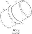
- a J-lay collar 10 as known in the prior art is a one-piece forging of steel.
- the collar 10 comprises a circumferential flange 12 disposed between opposed tubular end sections 14.
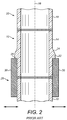
- the end sections 14 of the collar 10 are aligned along a mutual central longitudinal axis 16.
- Figure 2 also shows that the end sections 14 have end chamfers to facilitate welding to abutting pipe joints 18 that are also aligned along the central longitudinal axis 16.
- the flange 12 has a radially outer face 22 that encircles the collar 10 as a narrow circumferential band.
- a frusto-conical upper face 24 of the flange 12 extends at a shallow incline from one of the end sections 14 to the outer face 22.
- a lower face 26 of the flange 12 extends in a radially-outward direction from the other of the end sections 14 to the outer face 22.
- references to 'upper' and 'lower' relate to when the pipe string 20 is oriented upright for J-lay operations as shown in Figure 2 .
- the lower face 26 has a much steeper incline than the upper face 24 relative to the end sections 14 and the parallel central longitudinal axis 16; indeed, the lower face 26 extends substantially orthogonally relative to the end section 14 in this example for weight bearing on a bushing 28 as shown in Figure 2 .
- Figure 2 shows how the orthogonally-extending lower face 26 of the flange 12 serves as a shoulder to lie on top of, and hence to engage mechanically with, a tubular bushing 28 that encircles the J-lay collar 10 under the flange 12.
- the bushing 28 comprises bush sections 30 that are movable radially inwardly to come together and engage under the lower face 26 of the flange 12.
- the bush sections 30 are movable radially outwardly to split apart and hence to disengage from the lower face 26 to free the pipe string 20 for lowering through the open bushing 28 toward the sea.
- the flange 12 and the surrounding bare metal of the J-lay collar 10 and the adjoining pipe joints 18 must be coated with a protective and thermally-insulating coating.
- a protective and thermally-insulating coating it is problematic to ensure that the coating is continuous around the J-lay collar 10 and robust, especially where the shape of the collar 10 introduces sharp angles that may concentrate stress as the pipe string 20 moves and bends during installation and in use.
- the coating operation also introduces a safety risk because offshore personnel must work beneath the J-lay tower of a pipelaying vessel and in particular beneath the level from which the load of the pipeline catenary is suspended.
- the whole catenary must be lifted to make the J-lay collar 10 accessible for coating, typically by injection moulding of a polymer such as polypropylene ('PP') or polyurethane ('PU') using a mould tool positioned around the collar 10.
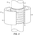
- FIGS 3 and 4 show a pipe joint 32 in accordance with the invention.
- the pipe joint 32 is suitable for offshore fabrication and installation of a subsea pipeline in a J-lay operation that involves end-to-end welding of successive abutting pipe joints to form a pipe string.
- the pipe joint 32 is coated with a longitudinally-continuous, thermally-insulating coating 34 of plastics material.
- the coating 34 has a radially outer surface that is shaped to define integral external hold-back formations 36.
- PP may be used as a coating 34 for the pipe joint 32 of the invention.
- a three-layer PP (3LPP) coating comprises a first layer of epoxy primer, a second thin layer of PP bonded to the primer and a third, thicker layer of extruded PP applied over the second layer.
- a five-layer PP (5LPP) coating adds two further layers, namely a fourth layer of PP modified for additional thermal insulation, such as glass syntactic PP (GSPP) or a foam, surrounded by a fifth layer of extruded PP for mechanical protection of the insulating fourth layer. Similar additional layers are possible for further thermal insulation, as in a seven-layer PP (7LPP) coating.
- Other plastics materials such as PU are also possible for the coating 34.
- thermoplastic polymers or thermoset polymers may be used for coating a pipe joint 32 of the invention.
- the invention removes the need for a separate, expensive forged J-lay collar 10, the need to incorporate such a collar 10 into a pipeline by welding, and the need subsequently to coat the collar 10.
- the invention does so by instead using the longitudinally-continuous, thermally-insulating coating 34 to support - and preferably, as shown in Figures 3 and 4 , to define - external hold-back formations 36.
- the thermally-insulating coating 34 extends continuously in a longitudinal direction and lies radially inwardly of the hold-back formations 36.
- the hold-back formations 36 allow a pipe string to be suspended safely in J-lay operations without interrupting the thermal insulation system of the pipeline or requiring a subsequent coating operation to be performed on the pipe string around the hold-back formations 36. This simplifies the pipelaying operation and improves safety; it also saves cost and valuable time.
- the hold-back formations 36 shown in Figures 3 and 4 comprise an array of circumferential flanges or ribs 38 that project radially from and surround the coated pipe joint 32 as a longitudinal series.
- the ribs 38 are axially distinct from one another and may be spaced from neighbouring ribs 38 or may abut neighbouring ribs 38.
- the ribs 38 may be regarded as a part of the coating 34 that defines the radially outer surface of the coating 34 in the region of the hold-back formations 36. However, it may also be said that the coating 34 is interposed between the ribs 38 and the underlying steel tube of the pipe joint 32.
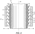
- each rib 38 has frusto-conical upper and lower faces 40, 42 that converge in the radially outward direction to meet at an apical circumferential edge 44.
- the upper and lower faces 40, 42 of the ribs 38 could have other shapes; similarly, the edge 44 of a rib 38 could instead be widened to form a circumferential band.
- the lower face 42 of each rib 38 has a shallower inclination than the upper face 40 relative to the adjoining or underlying outer cylindrical surface 46 of the coated pipe joint 32, which extends parallel to the central longitudinal axis 48.
- the lower face 42 is at a smaller and hence more acute angle than the upper face 40 to the outer surface 46 of the pipe joint 32.
- the lower face 42 has a greater longitudinal extent than the upper face 40, being larger, longer or wider in the longitudinal direction than the upper face 40.
- the lower face 42 has a greater surface area than the upper face 40.
- Figures 3 and 4 show how the external hold-back formations 36 engage mechanically with a tubular bushing 50 that encircles the formations.
- the bushing 50 comprises bush sections 52 that are movable radially inwardly to come together and engage the hold-back formations 36.
- the bush sections 52 are movable radially outwardly to split apart and hence to disengage from the hold-back formations 36 to free a pipe string comprising the pipe joint 32 for lowering toward the sea.
- the radially inner faces of the bush sections 52 are shaped to complement the hold-back formations 36, hence comprising circumferentially-extending grooves 54 that each receive a respective one of the ribs 38.
- the grooves 54 complement the shape of the ribs 38 by each having a steeply-inclined upper face 56 and a shallowly-inclined lower face 58 relative to the central longitudinal axis 48.
- the bushing 50 surrounds and embraces the hold-back formations 36, simultaneously engaging multiple ribs 38 in multiple grooves 54 rather than merely sitting under a single flange 12 of a J-lay collar 10 as in the prior art shown in Figures 1 and 2 .
- the inverted rib profile of the invention is counter-intuitive when compared to the shoulder profile of prior art J-lay collars.
- a shoulder is apt for making a conventional J-lay collar because steel can readily withstand shear stress. It has been found that such a shoulder is not apt for the plastics hold-back formations 36 that are enabled by the invention.
- the pipe joint 32 is held back by transferring shear loads through the coating 34 to the bushing 50 via the hold-back formations 36. This gives rise to the reverse-triangle interface profile that characterises preferred embodiments of the invention, which places more material in the lower portions of the hold-back formations 36 defined by the array of ribs 38.
- each rib 38 may be described as triangular, frusto-conical, tapered, downwardly-narrowing or wedge-shaped.
- the angle of inclination of the underside or lower face 42 is preferably acute relative to the central longitudinal axis 48 and may encompass values around 45°.
- the best trade-off between maximum area of the surface of contact, loads, and shear stress concentration may be between 35° and 40°.
- the hold-back formations 36 of the invention can be created or provided in various ways.
- One example is by over-moulding polymer ribs 38 onto a pre-applied polymer pipe coating 34 as shown in Figure 5 .
- a tubular mould tool 60 is clamped in part-tubular sections around a coated pipe 32 to define an annular mould cavity 62.
- the mould tool 60 has a radially inner face comprising a longitudinally-extending series of circumferentially-extending grooves 64 that are shaped to define the ribs 38.
- Molten thermoplastic polymer or a thermoset resin is injected into the mould cavity through gates 66 supplied from a source 68 such as an injection machine. When the polymer fills the mould cavity 62 and has hardened by cooling or curing, the mould tool 60 is removed to leave the ribs 38 standing proud of the pipe coating 34.
- Figures 6a and 6b show another approach to providing the hold-back formations of the invention.
- the ribs 38 are integral with part-tubular shells 70 that are assembled around a coated pipe joint 32 and bonded or welded to the coating 34 of the pipe joint 32.
- the resulting adhesive bond or weld 72 is shown between the coating 34 and a shell 70 in Figure 6b .
- the ribs 38 then become integral with the coating 34.
- the ribs 38 may be moulded integrally with a shell 70 as shown in Figures 6a and 6b , the ribs 38 and the shell 70 then both conveniently being of polymer material.
- the underlying pipe coating 34 will assure continuous thermal insulation, it would in principle be possible for the shell 70 and the ribs 38 instead to be machined, cast or forged of a metal such as steel.
- Composite materials are also possible for the ribs 38 and/or the shell 70.
- a unifying shell 70 is a convenient way to support and attach multiple ribs 38, one or more ribs 38 could instead be attached to the pipe coating 34 individually by bonding or welding if desired.
- Figure 7 shows the coating 34 of a pipe joint 32 comprising a layer 74 of PP modified for additional thermal insulation, such as glass syntactic PP (GSPP) or a foam.
- a layer 74 characterises a 5LPP or 7LPP coating.
- the modified layer 74 is surrounded by an outer layer 76 of extruded PP for mechanical protection. It will be apparent that the ribs 38 are supported by that outer layer 76 rather than by the modified layer 74, thus being overmoulded on the outer layer 76 to become integral with or part of the outer layer 76, or being bonded or welded to the outer layer 76.
- Figure 8 corresponds to Figure 4 but shows a variant of the hold-back formations 36 and omits the bushing 50 for clarity. Like numerals are used for like parts.
- the upper and lower faces 40, 42 of the ribs 38 are equally and oppositely inclined relative to the central longitudinal axis 48.
- the upper and lower faces 40, 42 of the ribs 38 may each be inclined at about 45° to the central longitudinal axis 48 as shown.
- Figure 9 puts the invention into its context of use by showing a pipelaying vessel 78 on the surface 80 of the sea performing a J-lay operation to install a rigid subsea pipeline 82 onto the seabed 84.
- the pipeline 82 when installed, serves as a flowline to carry production fluids from or to a subsea structure 86 on the seabed 84, such as wellhead or a termination module.
- the water depth will be very much greater than is represented schematically here.
- the vessel 78 has an upright J-lay tower 88 into which pipe joints 32 shown in Figures 3 to 7b are lifted to be welded to the top of a pipe string 90 that hangs as a catenary toward the seabed 84.
- the J-lay tower 88 is shown here as being vertical for simplicity but in practice it could be pivoted or gimballed to depart from the vertical. Welding operations are performed at a welding station 92 near the base of the tower 88.
- the lower bushing 94 and the travelling clamp 96 are each arranged to engage with hold-back formations 36 of the invention surrounding a thermal coating 34 of the pipe joints 32 as shown in Figures 3 to 7b .
- the lower bushing 94 and the travelling clamp 96 cooperate in a hand-over-hand arrangement to lower the pipe string 90 as successive pipe joints 32 are added.
Description
- This invention relates to supporting an elongate element from a surface vessel during an offshore operation. An example of such an element is a subsea pipeline that hangs as a catenary from a surface vessel toward the seabed during installation. In the art of subsea operations, supporting such an element may be referred to as 'holding back' or 'hanging off'.
- The main methods for installing subsea pipelines are known in the art as reel-lay, S-lay and J-lay.
- In reel-lay operations, a pipeline of rigid or flexible pipe is initially spooled onto and stored on a reel on an installation vessel, which visits a coastal spoolbase at which the pipeline is fabricated. During installation offshore, the pipeline is unspooled from the reel and then overboarded into the sea to hang from the vessel as a catenary. Between unspooling and overboarding, the pipeline may pass through various types of equipment, such as tensioners, a tower, a ramp, a stinger or - if the pipeline is of rigid pipe - a straightener. The main hold-back forces are applied to the pipeline by the tensioners and the reel.
- In S-lay operations, the pipeline is assembled from pipe joints along a horizontal firing line on an installation vessel offshore. As it is assembled, the pipeline is launched into the sea over a laying ramp or stinger to hang from the vessel as a catenary. The pipeline assumes an S-shape comprising an overbend over the stinger and an opposed sagbend approaching the seabed. Again, the catenary is held back by tensioners on the installation vessel.
- In J-lay operations, in contrast, the pipeline is assembled from pipe joints in an upright tower on an installation vessel offshore. The pipeline hangs near-vertically to a sagbend approaching the seabed, thus assuming a J-shape. In this case, the catenary is held back by friction clamps or by a collar arrangement that is co-operable with bushings on the installation vessel. As friction clamps and collar/bushing arrangements are both static relative to the pipeline, this allows the pipelaying equipment of J-lay to be more compact and less massive than the tensioners that typify reel-lay and S-lay.
- Pipeline installation in deep water requires the installation vessel to have a high hold-back capacity. This is due to the great weight of the long catenary of pipeline that is suspended between the vessel and the seabed.
- The hold-back capacity of tensioners is limited because their endless-loop architecture limits the transverse pressure and consequently the longitudinal friction forces they can apply to a pipeline. For heavy pipelines such as large-diameter rigid pipelines, the weight of the catenary may be great enough to overcome the friction capacity of tensioners that are available to hold the pipeline. Consequently, the J-lay method is favoured for use where the water depth is great (for example, more than about 1000m) and the pipeline is heavy.
- At least two friction clamps or bushings are needed to lower a pipeline in J-lay operations. One of those clamps or bushings is movable reciprocally relative to the J-lay tower in opposed directions parallel to the lay direction to hold back and lower the pipeline in a hand-over-hand arrangement. For example,
WO 2010/059035 features a combination of several collars and bushings. - Friction clamps are specifically designed to maximise frictional hold-back forces at the interface with the outer surface of the pipeline. Examples are disclosed in
GB 2370335 WO 01/35011 US 2014/334879 andWO 2009/153354 . Pads of the friction clamp hold the pipeline with friction generated by radially-inward squeezing force. The pads may have a special design for increasing the surface area of contact. For example, pads of the friction clamp disclosed inUS 2014/334879 include protrusions that embed into the surface of the pipeline, to enhance frictional engagement by increasing a contact area between the clamp and the pipe. - In more distant prior art,
US 2014/079486 discloses a friction clamp for gripping an umbilical having a smooth outer surface relative to another elongate element such as a pipeline. - The main drawback of friction clamps is their total reliance upon friction. This is disadvantageous because there is nothing to hold the pipeline if it starts to slip through the clamp, for example because the outer surface of the pipeline has a poor surface finish or is wet or oily.
- In the alternative of a collar arrangement, also known as a J-lay collar, the collar is a metallic part of the pipeline that defines a radially-projecting ring. Examples are a forged radially-projecting ring welded to the pipeline, or a forging comprising such a ring that is welded to an end of a pipe joint of the pipeline. The collar mechanically engages a hold-back bushing on the pipelaying vessel, thus providing a steady and reliable mechanical connection between the laying equipment and the pipeline. For example,
WO 99/01638 WO 2009/083937 discloses a pipe-in-pipe structure with several J-lay collars on the same pipe.US 2011/0226373 andUS6334739 provide further examples of J-lay collars, and a J-lay collar is also illustrated inFigures 1 and2 , which will be described later. - J-lay collars have various drawbacks, including the cost of the specific forged pieces and the time and complexity of welding them into the pipeline. For example, the area around the interface between a collar and a pipe joint has to be bare steel to allow welding. Also, welding requires specific welding processes and qualifications because the metallurgical quality of the steels to be welded together is not homogeneous. In particular, a seamless pipe joint is made of an extruded billet of carbon steel whereas a forged collar has other phases in its metallurgical composition, being more ferritic or pearlitic.
- After welding, a thermal insulation coating has to be applied to cover the full pipe section including the collars. Coating is performed in a work station that is situated beneath the hold-back bushing and so is beneath the welding station, which is risky for offshore crew. The quality and evenness of the thermal insulation coating around the radially-projecting ring of the collar is also a concern: a thermoplastic coating may not bond sufficiently with the discontinuous shape of the steel collar.
- Effective thermal insulation is an important requirement for many subsea pipelines, especially those used to transport crude oil or natural gas from subsea wellheads. Oil and gas are present in subterranean formations at elevated temperature and pressure, which may be increased by the injection of fluids such as steam. As collected at the outlet of a wellhead, crude oil is a viscous, multiphasic, pressurised fluid whose temperature is typically around 100°C to 180°C but may be higher. If the crude oil is allowed to cool too much, some components of the oil may solidify by mechanisms such as coalescence, precipitation or gelling. The waxes, asphaltenes, hydrates or other solid condensates that appear as a result may form a plug that will clog the pipeline and be difficult to remove. Similar issues may arise in subsea pipelines used to transport natural gas.
- Thus, during transportation along the pipeline, the temperature and pressure of the produced fluid have to be kept high enough to ensure a sufficient flow rate. In particular, various measures are taken to ensure that the internal temperature of the pipeline remains high, typically above 65°C and in some cases above 200°C, despite thermal exchange with seawater which, for example, is at 4°C below 1000m depth.
- In addition, an oil or gas field must occasionally be shut down for maintenance. During shut-down, production is stopped and so no hot fluid flows through the pipeline. Consequently, to avoid clogging by solid-phase materials, mitigating fluid such as methanol or diesel oil is injected into the pipeline during shut-down. When production restarts, temperature within the pipeline must be increased quickly so that no plugs will form.
- It is important to maintain thermal management continuously along the length of a pipeline. Otherwise, 'cold spots' will arise, which increases the likelihood of plugs forming at those locations. J-lay collars increase the risk of cold spots.
-
GB2498808A - Against this background, the invention addresses the conflicting challenges of providing a hold-back system for use in J-lay operations that is inexpensive, reliable and safe for offshore personnel and yet does not jeopardise thermal insulation of a pipeline.
- In one sense, the invention resides in a pipe joint for offshore fabrication and installation of a pipeline in a J-lay operation. The pipe joint comprises: a length of pipe; a thermally-insulating coating around the length of pipe; and a radially outer surface shaped to define a series of external radially-projecting hold-back formations disposed in longitudinal succession along the pipe joint, the hold-back formations being configured to facilitate suspending of the pipe joint during the J-lay operation, each hold-back formation being a ridge that extends continuously around the pipe joint circumferentially. The coating extends continuously along the pipe on a radially inner side of each hold-back formation and is interposed between each hold-back formation and the pipe. When a central longitudinal axis of the pipe joint is upright, a downwardly-facing face of each hold-back formation has a substantially frusto-conical surface inclined at an acute angle relative to the central longitudinal axis of the pipe joint.
- Each hold-back formation is preferably integral with the coating and may be overmoulded onto the coating or attached to the coating by bonding or welding. For example, each hold-back formation may be supported by a shell that is bonded or welded to the coating.
- It is preferred that each hold-back formation is wholly or predominantly of plastics material. For example, a hold-back formation could comprise reinforcing fibres in a plastics matrix.
- The coating may be a 3LPP coating or a layered coating, such as a 5LPP coating, that comprises at least one layer modified for additional thermal insulation and an outer mechanically-protective layer around the or each modified layer. In that case, the hold-back formations are suitably integral with or attached to the outer mechanically-protective layer.
- Conveniently, the ridge may be defined by a pair of oppositely-inclined generally frusto-conical faces that converge with each other in a radially outward direction to terminate in an outer edge or band. In that case, the faces of the pair preferably have differing acute angles of inclination relative to the central longitudinal axis of the pipe joint. More particularly, when the central longitudinal axis of the pipe joint is upright, an upper face of the pair preferably has a greater angle of inclination relative to that axis than a lower face of the pair.
- The inventive concept embraces a subsea pipeline comprising at least one pipe joint of the invention.
- Also within the inventive concept is a method of manufacturing a pipe joint for offshore fabrication and installation of a pipeline in a J-lay operation. The method comprises: applying a thermally-insulating coating onto a length of pipe; and forming or attaching a longitudinal succession of external radially-projecting hold-back formations onto the coating, each hold-back formation being a ridge that extends continuously around the pipe joint circumferentially and being configured to facilitate suspending of the pipe joint during the J-lay operation. When a central longitudinal axis of the pipe joint is upright, a downwardly-facing face of each hold-back formation has a substantially frusto-conical surface inclined at an acute angle relative to the central longitudinal axis of the pipe joint.
- The method may comprise overmoulding each hold-back formation onto the coating or bonding or welding each hold-back formation onto the coating. A shell may be bonded or welded onto the coating, which shell supports one or more hold-back formations.
- The inventive concept may also be expressed as a J-lay method for offshore fabrication and installation of a pipeline. The method comprises: attaching a pipe joint to an upper end of a pipe string catenary suspended from an installation vessel, the pipe joint comprising a thermally-insulating coating around a length of pipe, which coating extends continuously along the pipe and is interposed between a longitudinal succession of external radially-projecting hold-back formations and the pipe, each hold-back formation being a ridge that extends continuously around the pipe joint circumferentially and being configured to facilitate suspending of the pipe joint during a J-lay operation; and holding back a weight load of the catenary using a bushing or clamp of the vessel engaged with each hold-back formation. When a central longitudinal axis of the pipe joint is upright, a downwardly-facing face of each hold-back formation has a substantially frusto-conical surface inclined at an acute angle relative to the central longitudinal axis of the pipe joint.
- The weight load is suitably transferred from the catenary to the bushing or clamp by shear forces acting through the coating. Preferably, the weight load is transferred from the coating to the bushing or clamp through a lower face of at least one radially-projecting hold-back formation to an opposed face of the bushing or clamp, which faces are inclined at matching acute angles relative to a common central longitudinal axis.
- Advantageously, the pipe joint may be loaded onto the installation vessel with each hold-back formation already provided on the pipe joint.
- In summary, preferred embodiments of the invention provide a radially-projecting plastics formation that is suitably integral with a pipeline coating. Various formation shapes are possible to improve load capacity and to secure the system.
- In use in a J-lay operation, the stress path leads from the pipeline to the radially-projecting formation and from there to a purposely-designed complementary hold-back bushing. The axial hold-back load that must be transferred through the coating and the formation is so high in J-lay operations that the formation needs a special design to withstand the resulting shear stress.
- As the radially-projecting plastics formation may be pre-formed or prefabricated on a pipe joint, the only coating that has to be made offshore is a conventional field joint coating between adjoining pipe joints.
- The application also describes a method to install a pipeline in seawater, which method comprises: preliminarily manufacturing or otherwise providing a radially-projecting formation on a coating of at least one section of the pipeline, which formation is preferably polymeric; and offshore J-laying a pipeline comprising said section, the weight of the pipeline catenary being held back during at least one step of J-laying by a bushing or clamp of an installation vessel that engages said formation.
- The application also describes a device, equipment or apparatus for laying a pipeline in seawater, the apparatus comprising: at least one radially-projecting formation on at least one coated section of the pipeline, which formation is provided on the coating of the pipeline section; and a complementary bushing or clamp mounted on an installation vessel, which bushing or clamp is suitable to engage the projecting formation and to hold back the tension in a pipeline catenary suspended from the installation vessel via the projecting formation.
- The projecting formation may comprise at least two, and preferably at least three, radially-projecting rings that are distinct in the axial direction. The projecting formation is suitably of plastics material or has a plastics matrix containing reinforcements such as fibres. The projecting formation may be bonded to the coating or moulded over the coating.
- The projecting formation may be engaged by a static bushing and/or a travelling clamp of a hand-over-hand J-lay installation system.
- The invention is primarily concerned with rigid pipelines. In this respect, it is important to understand that the terms 'rigid' and 'flexible' as applied to pipes have clear meanings in the subsea oil and gas industry that differ in important respects from general language. For example, nominally 'rigid' pipes have enough flexibility to be bent if a minimum bend radius is observed. Yet, such pipes are not regarded in the industry as being 'flexible'.
- Flexible pipes used in the subsea oil and gas industry are specified in API (American Petroleum Institute) Specification 17J and API Recommended Practice 17B. The pipe body is composed of a composite structure of layered materials, in which each layer has its own function.
- The structure of a flexible pipe allows a large bending deflection without a similarly large increase in bending stresses. The bending limit of the composite structure is determined by the elastic limit of the outermost plastics layer of the structure, typically the outer sheath, which limit is typically 6% to 7% bending strain. Exceeding that limit causes irreversible damage to the structure. Consequently, the minimum bending radius or MBR of flexible pipe used in the subsea oil and gas industry is typically between 3 and 6 metres.
- Conversely, rigid pipes used in the subsea oil and gas industry are specified in API Specification 5L and Recommended Practice 1111. In contrast to flexible pipes, a rigid pipe usually consists of or comprises at least one pipe of solid steel or steel alloy. However, additional elements can be added, such as an internal liner layer or an outer coating layer. Such additional elements can comprise polymer, metal or composite materials. Rigid pipe joints are typically terminated by a bevel or a thread, and are assembled end-to-end by welding or screwing them together.
- The allowable in-service deflection of rigid steel pipe is determined by the elastic limit of steel, which is around 1% bending strain. Exceeding this limit caused plastic deformation of the steel. It follows that the MBR of rigid pipe used in the subsea oil and gas industry is typically around 100 to 300 metres depending upon the cross-sectional dimensions of the pipe.
- Whilst rigid pipes have traditionally been of metal, specifically steel, there has been progress in the art toward the use of composite materials for subsea pipes. Such materials typically comprise reinforcing fibres embedded in a polymer matrix. As the bending behaviour of a composite pipe may broadly emulate that of steel pipe in the elastic domain, pipes of composite materials may be regarded as a form of rigid pipe. Thus, if further development in the art leads to the use of composite materials for pipes to be installed by J-lay, the invention could, in principle, be applied to such pipes.
- In order that the invention may be more readily understood, reference will now be made, by way of example, to the accompanying drawings in which:
-
Figure 1 is a perspective view of a forged steel J-lay collar known in the prior art; -
Figure 2 is a schematic sectional side view through the J-lay collar ofFigure 1 , now incorporated by welding into an upright pipeline during a J-lay operation and hanging off a hold-back bushing on an installation vessel; -
Figure 3 is a perspective view of a pipeline in accordance with the invention, showing a thermally-insulating coating of the pipeline shaped to define hold-back formations surrounded by a complementarily-shaped hold-back bushing; -
Figure 4 is a schematic sectional side view through the pipeline and bushing ofFigure 3 ; -
Figure 5 is a schematic sectional side view through a coated pipeline and a mould tool that encircles the pipeline to overmould the hold-back formations on the coating; -
Figures 6a and 6b are enlarged detail views showing a variant of the invention in which the hold-back formations are defined by a shell that is shown separately from a coated pipeline inFigure 6a and bonded or welded to the coating inFigure 6b ; -
Figure 7 is an enlarged detail view showing a variant of the invention in which the coating is layered, in this case being a 5LPP coating including a layer of foam insulation; -
Figure 8 corresponds toFigure 4 but shows a variant of the hold-back formations and omits the bushing; and -
Figure 9 is a schematic sectional side view of a J-lay vessel in the process of pipelaying, showing the invention in its context of use. - Referring firstly to
Figures 1 and2 of the drawings, a J-lay collar 10 as known in the prior art is a one-piece forging of steel. Thecollar 10 comprises acircumferential flange 12 disposed between opposedtubular end sections 14. - As shown in
Figure 2 , theend sections 14 of thecollar 10 are aligned along a mutual centrallongitudinal axis 16.Figure 2 also shows that theend sections 14 have end chamfers to facilitate welding to abutting pipe joints 18 that are also aligned along the centrallongitudinal axis 16. This incorporates thecollar 10 into apipe string 20 that will comprise manysuch collars 10 and pipe joints 18. - The
flange 12 has a radiallyouter face 22 that encircles thecollar 10 as a narrow circumferential band. A frusto-conicalupper face 24 of theflange 12 extends at a shallow incline from one of theend sections 14 to theouter face 22. Alower face 26 of theflange 12 extends in a radially-outward direction from the other of theend sections 14 to theouter face 22. In this respect, references to 'upper' and 'lower' relate to when thepipe string 20 is oriented upright for J-lay operations as shown inFigure 2 . - It will be noted that the
lower face 26 has a much steeper incline than theupper face 24 relative to theend sections 14 and the parallel centrallongitudinal axis 16; indeed, thelower face 26 extends substantially orthogonally relative to theend section 14 in this example for weight bearing on abushing 28 as shown inFigure 2 . - Specifically,
Figure 2 shows how the orthogonally-extendinglower face 26 of theflange 12 serves as a shoulder to lie on top of, and hence to engage mechanically with, atubular bushing 28 that encircles the J-lay collar 10 under theflange 12. Thebushing 28 comprisesbush sections 30 that are movable radially inwardly to come together and engage under thelower face 26 of theflange 12. Conversely, thebush sections 30 are movable radially outwardly to split apart and hence to disengage from thelower face 26 to free thepipe string 20 for lowering through theopen bushing 28 toward the sea. - Before reaching the sea, the
flange 12 and the surrounding bare metal of the J-lay collar 10 and the adjoining pipe joints 18 must be coated with a protective and thermally-insulating coating. As noted in the introduction, it is problematic to ensure that the coating is continuous around the J-lay collar 10 and robust, especially where the shape of thecollar 10 introduces sharp angles that may concentrate stress as thepipe string 20 moves and bends during installation and in use. - The coating operation also introduces a safety risk because offshore personnel must work beneath the J-lay tower of a pipelaying vessel and in particular beneath the level from which the load of the pipeline catenary is suspended. In this respect, when a new pipe joint 18 has been welded to the top of the
pipe string 20, the whole catenary must be lifted to make the J-lay collar 10 accessible for coating, typically by injection moulding of a polymer such as polypropylene ('PP') or polyurethane ('PU') using a mould tool positioned around thecollar 10. - Turning next to
Figures 3 and4 , these show a pipe joint 32 in accordance with the invention. The pipe joint 32 is suitable for offshore fabrication and installation of a subsea pipeline in a J-lay operation that involves end-to-end welding of successive abutting pipe joints to form a pipe string. - The pipe joint 32 is coated with a longitudinally-continuous, thermally-insulating
coating 34 of plastics material. In this example of the invention, thecoating 34 has a radially outer surface that is shaped to define integral external hold-back formations 36. - As is conventional in the art, PP may be used as a
coating 34 for thepipe joint 32 of the invention. For example, a three-layer PP (3LPP) coating comprises a first layer of epoxy primer, a second thin layer of PP bonded to the primer and a third, thicker layer of extruded PP applied over the second layer. A five-layer PP (5LPP) coating adds two further layers, namely a fourth layer of PP modified for additional thermal insulation, such as glass syntactic PP (GSPP) or a foam, surrounded by a fifth layer of extruded PP for mechanical protection of the insulating fourth layer. Similar additional layers are possible for further thermal insulation, as in a seven-layer PP (7LPP) coating. Other plastics materials such as PU are also possible for thecoating 34. In general, thermoplastic polymers or thermoset polymers may be used for coating apipe joint 32 of the invention. - Unconventionally, the invention removes the need for a separate, expensive forged J-
lay collar 10, the need to incorporate such acollar 10 into a pipeline by welding, and the need subsequently to coat thecollar 10. The invention does so by instead using the longitudinally-continuous, thermally-insulatingcoating 34 to support - and preferably, as shown inFigures 3 and4 , to define - external hold-back formations 36. In other words, the thermally-insulatingcoating 34 extends continuously in a longitudinal direction and lies radially inwardly of the hold-back formations 36. - By virtue of this arrangement, the hold-
back formations 36 allow a pipe string to be suspended safely in J-lay operations without interrupting the thermal insulation system of the pipeline or requiring a subsequent coating operation to be performed on the pipe string around the hold-back formations 36. This simplifies the pipelaying operation and improves safety; it also saves cost and valuable time. - The hold-
back formations 36 shown inFigures 3 and4 comprise an array of circumferential flanges orribs 38 that project radially from and surround the coated pipe joint 32 as a longitudinal series. Theribs 38 are axially distinct from one another and may be spaced from neighbouringribs 38 or may abut neighbouringribs 38. - In effect, the
ribs 38 may be regarded as a part of thecoating 34 that defines the radially outer surface of thecoating 34 in the region of the hold-back formations 36. However, it may also be said that thecoating 34 is interposed between theribs 38 and the underlying steel tube of the pipe joint 32. - In this example, each
rib 38 has frusto-conical upper and lower faces 40, 42 that converge in the radially outward direction to meet at an apicalcircumferential edge 44. However, the upper and lower faces 40, 42 of theribs 38 could have other shapes; similarly, theedge 44 of arib 38 could instead be widened to form a circumferential band. - When the pipe joint 32 is upright as in a J-lay operation, the
lower face 42 of eachrib 38 has a shallower inclination than theupper face 40 relative to the adjoining or underlying outercylindrical surface 46 of the coated pipe joint 32, which extends parallel to the centrallongitudinal axis 48. In other words, thelower face 42 is at a smaller and hence more acute angle than theupper face 40 to theouter surface 46 of the pipe joint 32. Put another way, thelower face 42 has a greater longitudinal extent than theupper face 40, being larger, longer or wider in the longitudinal direction than theupper face 40. Thus, thelower face 42 has a greater surface area than theupper face 40. - This relationship between the upper and lower faces 40, 42 of each
rib 38 is in complete contrast to the prior art shown inFigures 1 and2 , in which thelower face 26 of theflange 12 typically has a much greater inclination than theupper face 24 of theflange 12 relative to the outer surface of anend section 14 of the J-lay collar 10 and indeed simply extends orthogonally from that outer surface. -
Figures 3 and4 show how the external hold-back formations 36 engage mechanically with atubular bushing 50 that encircles the formations. As in the prior art, thebushing 50 comprisesbush sections 52 that are movable radially inwardly to come together and engage the hold-back formations 36. Similarly, thebush sections 52 are movable radially outwardly to split apart and hence to disengage from the hold-back formations 36 to free a pipe string comprising the pipe joint 32 for lowering toward the sea. - The radially inner faces of the
bush sections 52 are shaped to complement the hold-back formations 36, hence comprising circumferentially-extendinggrooves 54 that each receive a respective one of theribs 38. Thegrooves 54 complement the shape of theribs 38 by each having a steeply-inclinedupper face 56 and a shallowly-inclinedlower face 58 relative to the centrallongitudinal axis 48. Thus, thebushing 50 surrounds and embraces the hold-back formations 36, simultaneously engagingmultiple ribs 38 inmultiple grooves 54 rather than merely sitting under asingle flange 12 of a J-lay collar 10 as in the prior art shown inFigures 1 and2 . This improves the security of mechanical engagement and beneficially spreads the weight of the suspended pipe joint 32 over a greater length and hence over a greater area of the pipe joint 32 and itscoating 34. The result is a capability to sustain a high catenary load, which may for example be in the order of 300 metric tonnes. - It will be apparent that the inverted rib profile of the invention is counter-intuitive when compared to the shoulder profile of prior art J-lay collars. A shoulder is apt for making a conventional J-lay collar because steel can readily withstand shear stress. It has been found that such a shoulder is not apt for the plastics hold-
back formations 36 that are enabled by the invention. In the invention, the pipe joint 32 is held back by transferring shear loads through thecoating 34 to thebushing 50 via the hold-back formations 36. This gives rise to the reverse-triangle interface profile that characterises preferred embodiments of the invention, which places more material in the lower portions of the hold-back formations 36 defined by the array ofribs 38. - At least the underside or
lower face 42 of eachrib 38 may be described as triangular, frusto-conical, tapered, downwardly-narrowing or wedge-shaped. The angle of inclination of the underside orlower face 42 is preferably acute relative to the centrallongitudinal axis 48 and may encompass values around 45°. For example, the best trade-off between maximum area of the surface of contact, loads, and shear stress concentration may be between 35° and 40°. - The hold-
back formations 36 of the invention can be created or provided in various ways. One example is byover-moulding polymer ribs 38 onto a pre-appliedpolymer pipe coating 34 as shown inFigure 5 . Here, atubular mould tool 60 is clamped in part-tubular sections around acoated pipe 32 to define anannular mould cavity 62. Themould tool 60 has a radially inner face comprising a longitudinally-extending series of circumferentially-extendinggrooves 64 that are shaped to define theribs 38. Molten thermoplastic polymer or a thermoset resin is injected into the mould cavity throughgates 66 supplied from asource 68 such as an injection machine. When the polymer fills themould cavity 62 and has hardened by cooling or curing, themould tool 60 is removed to leave theribs 38 standing proud of thepipe coating 34. -
Figures 6a and 6b show another approach to providing the hold-back formations of the invention. Here, theribs 38 are integral with part-tubular shells 70 that are assembled around a coated pipe joint 32 and bonded or welded to thecoating 34 of the pipe joint 32. The resulting adhesive bond orweld 72 is shown between thecoating 34 and ashell 70 inFigure 6b . In effect, theribs 38 then become integral with thecoating 34. - The
ribs 38 may be moulded integrally with ashell 70 as shown inFigures 6a and 6b , theribs 38 and theshell 70 then both conveniently being of polymer material. However, as theunderlying pipe coating 34 will assure continuous thermal insulation, it would in principle be possible for theshell 70 and theribs 38 instead to be machined, cast or forged of a metal such as steel. Composite materials are also possible for theribs 38 and/or theshell 70. - Whilst a unifying
shell 70 is a convenient way to support and attachmultiple ribs 38, one ormore ribs 38 could instead be attached to thepipe coating 34 individually by bonding or welding if desired. -
Figure 7 shows thecoating 34 of a pipe joint 32 comprising alayer 74 of PP modified for additional thermal insulation, such as glass syntactic PP (GSPP) or a foam. Such alayer 74 characterises a 5LPP or 7LPP coating. The modifiedlayer 74 is surrounded by anouter layer 76 of extruded PP for mechanical protection. It will be apparent that theribs 38 are supported by thatouter layer 76 rather than by the modifiedlayer 74, thus being overmoulded on theouter layer 76 to become integral with or part of theouter layer 76, or being bonded or welded to theouter layer 76. -
Figure 8 corresponds toFigure 4 but shows a variant of the hold-back formations 36 and omits thebushing 50 for clarity. Like numerals are used for like parts. In this variant, it will be apparent that the upper and lower faces 40, 42 of theribs 38 are equally and oppositely inclined relative to the centrallongitudinal axis 48. For example, the upper and lower faces 40, 42 of theribs 38 may each be inclined at about 45° to the centrallongitudinal axis 48 as shown. - Finally,
Figure 9 puts the invention into its context of use by showing apipelaying vessel 78 on thesurface 80 of the sea performing a J-lay operation to install a rigidsubsea pipeline 82 onto theseabed 84. In this example, thepipeline 82, when installed, serves as a flowline to carry production fluids from or to asubsea structure 86 on theseabed 84, such as wellhead or a termination module. In reality, the water depth will be very much greater than is represented schematically here. - The
vessel 78 has an upright J-lay tower 88 into which pipe joints 32 shown inFigures 3 to 7b are lifted to be welded to the top of apipe string 90 that hangs as a catenary toward theseabed 84. The J-lay tower 88 is shown here as being vertical for simplicity but in practice it could be pivoted or gimballed to depart from the vertical. Welding operations are performed at awelding station 92 near the base of thetower 88. - A fixed lower bushing 94 beneath the
welding station 92 and a travelling upper bushing or clamp 96 on the J-lay tower 88 support thepipe string 90 in alternation. Thus, the lower bushing 94 and the travellingclamp 96 are each arranged to engage with hold-back formations 36 of the invention surrounding athermal coating 34 of the pipe joints 32 as shown inFigures 3 to 7b . In conventional fashion, the lower bushing 94 and the travellingclamp 96 cooperate in a hand-over-hand arrangement to lower thepipe string 90 as successive pipe joints 32 are added.
Claims (20)
- A pipe joint (32) for offshore fabrication and installation of a pipeline in a J-lay operation, the pipe joint comprising:a length of pipe; anda thermally-insulating coating (34) around the length of pipe;the pipe joint having a radially outer surface shaped to define a series of external radially-projecting hold-back formations (36) disposed in longitudinal succession along the pipe joint (32), the hold-back formations (36) being configured to facilitate suspending of the pipe joint (32) during the J-lay operation, each hold-back formation (36) being a ridge (38) that extends continuously around the pipe joint (32) circumferentially;
wherein the coating (34) extends continuously along the pipe on a radially inner side of each hold-back formation (36) and is interposed between each hold-back formation (36) and the pipe;
characterised in that when a central longitudinal axis (48) of the pipe joint (32) is upright, a downwardly-facing face (42) of each hold-back formation (36) has a substantially frusto-conical surface inclined at an acute angle relative to the central longitudinal axis (48) of the pipe joint (32). - The pipe joint (32) of Claim 1, wherein each hold-back formation (36) is integral with the coating (34).
- The pipe joint (32) of Claim 1 or Claim 2, wherein each hold-back formation (36) is overmoulded onto the coating (34).
- The pipe joint (32) of Claim 1 or Claim 2, wherein each hold-back formation (36) is bonded or welded to the coating (34).
- The pipe joint (32) of Claim 4, wherein each hold-back formation (36) is supported by a shell (70) that is bonded or welded to the coating (34).
- The pipe joint (32) of any preceding claim, wherein each hold-back formation (36) is wholly or predominantly of plastics material.
- The pipe joint (32) of any preceding claim, wherein:the coating (34) is a layered coating that comprises at least one layer (74) modified for additional thermal insulation and an outer mechanically-protective layer (76) around the or each modified layer (74); andthe hold-back formations (36) are integral with or attached to the outer mechanically-protective layer (76).
- The pipe joint (32) of any preceding claim, wherein the ridge (38) is defined by a pair of oppositely-inclined substantially frusto-conical faces (40, 42) that converge with each other in a radially outward direction.
- The pipe joint (32) of Claim 8, wherein the faces (40, 42) of the pair have differing acute angles of inclination relative to the central longitudinal axis (48) of the pipe joint (32).
- The pipe joint (32) of Claim 9, wherein when the central longitudinal axis (48) of the pipe joint (32) is upright, an upper face (40) of the pair has a greater angle of inclination relative to that axis than a lower face (42) of the pair.
- The pipe joint (32) of any preceding claim, comprising a series of hold-back formations (36) disposed in longitudinal succession along the pipe joint (32).
- A subsea pipeline (82) comprising at least one pipe joint (32) as defined in any preceding claim.
- A method of manufacturing a pipe joint (32) for offshore fabrication and installation of a pipeline (82) in a J-lay operation, the method comprising applying a thermally-insulating coating (34) onto a length of pipe, the method including forming or attaching a longitudinal succession of external radially-projecting hold-back formations (36) onto the coating (34), each hold-back formation (36) being a ridge (38) that extends continuously around the pipe joint (32) circumferentially and being configured to facilitate suspending of the pipe joint (32) during the J-lay operation, characterised in that when a central longitudinal axis (48) of the pipe joint (32) is upright, a downwardly-facing face (42) of each hold-back formation (36) has a substantially frusto-conical surface inclined at an acute angle relative to the central longitudinal axis (48) of the pipe joint (32).
- The method of Claim 13, comprising overmoulding each hold-back formation (36) onto the coating (34).
- The method of Claim 13, comprising bonding or welding each hold-back formation (36) onto the coating (34).
- The method of Claim 15, comprising bonding or welding a shell (70) onto the coating (34), which shell (70) supports one or more hold-back formations (36).
- A J-lay method for offshore fabrication and installation of a pipeline (82), the method comprising:attaching a pipe joint (32) to an upper end of a pipe string (90) catenary suspended from an installation vessel (78), the pipe joint (32) comprising a thermally-insulating coating (34) around a length of pipe, which coating (34) extends continuously along the pipe and is interposed between a longitudinal succession of external radially-projecting hold-back formations (36) and the pipe, each hold-back formation (36) being a ridge (38) that extends continuously around the pipe joint (32) circumferentially and being configured to facilitate suspending of the pipe joint (32) during a J-lay operation, characterised in that, when a central longitudinal axis (48) of the pipe joint (32) is upright, a downwardly-facing face (42) of each hold-back formation (36) has a substantially frusto-conical surface inclined at an acute angle relative to the central longitudinal axis (48) of the pipe joint (32); andholding back a weight load of the catenary using a bushing (50) or clamp of the vessel (78) engaged with each hold-back formation (36).
- The method of Claim 17, wherein the weight load is transferred from the catenary to the bushing (50) or clamp by shear forces acting through the coating (34).
- The method of Claim 18, comprising transferring the weight load from the coating (34) to the bushing (50) or clamp through a lower face of at least one radially-projecting hold-back formation (36) to an opposed face of the bushing (50) or clamp, which faces are inclined at matching acute angles relative to a common central longitudinal axis (48).
- The method of any of Claims 17 to 19, wherein the pipe joint (32) is loaded onto the installation vessel (78) with each hold-back formation (36) already provided on the pipe joint (32).
Priority Applications (1)
| Application Number | Priority Date | Filing Date | Title |
|---|---|---|---|
| EP19189680.2A EP3591274B1 (en) | 2015-11-20 | 2016-11-16 | Holding back elongate elements during subsea operations |
Applications Claiming Priority (2)
| Application Number | Priority Date | Filing Date | Title |
|---|---|---|---|
| GB1520514.9A GB2544547B (en) | 2015-11-20 | 2015-11-20 | Holding back Elongate elements during subsea operations |
| PCT/IB2016/001803 WO2017085559A1 (en) | 2015-11-20 | 2016-11-16 | Holding back elongate elements during subsea operations |
Related Child Applications (2)
| Application Number | Title | Priority Date | Filing Date |
|---|---|---|---|
| EP19189680.2A Division EP3591274B1 (en) | 2015-11-20 | 2016-11-16 | Holding back elongate elements during subsea operations |
| EP19189680.2A Division-Into EP3591274B1 (en) | 2015-11-20 | 2016-11-16 | Holding back elongate elements during subsea operations |
Publications (2)
| Publication Number | Publication Date |
|---|---|
| EP3377794A1 EP3377794A1 (en) | 2018-09-26 |
| EP3377794B1 true EP3377794B1 (en) | 2020-08-19 |
Family
ID=55133120
Family Applications (2)
| Application Number | Title | Priority Date | Filing Date |
|---|---|---|---|
| EP19189680.2A Active EP3591274B1 (en) | 2015-11-20 | 2016-11-16 | Holding back elongate elements during subsea operations |
| EP16826438.0A Active EP3377794B1 (en) | 2015-11-20 | 2016-11-16 | Holding back elongate elements during subsea operations |
Family Applications Before (1)
| Application Number | Title | Priority Date | Filing Date |
|---|---|---|---|
| EP19189680.2A Active EP3591274B1 (en) | 2015-11-20 | 2016-11-16 | Holding back elongate elements during subsea operations |
Country Status (6)
| Country | Link |
|---|---|
| US (1) | US10527196B2 (en) |
| EP (2) | EP3591274B1 (en) |
| AU (1) | AU2016355234B2 (en) |
| BR (1) | BR112018008822B1 (en) |
| GB (1) | GB2544547B (en) |
| WO (1) | WO2017085559A1 (en) |
Families Citing this family (2)
| Publication number | Priority date | Publication date | Assignee | Title |
|---|---|---|---|---|
| GB2591473B (en) * | 2020-01-28 | 2022-03-23 | Subsea 7 Ltd | Attaching hold-back fixings to subsea pipelines |
| GB202003144D0 (en) * | 2020-03-04 | 2020-04-15 | Balmoral Comtec Ltd | Subsea line clamp assembly |
Family Cites Families (24)
| Publication number | Priority date | Publication date | Assignee | Title |
|---|---|---|---|---|
| US2498808A (en) * | 1947-12-15 | 1950-02-28 | Acme Visible Records Inc | Visible index embodying a plurality of swingable panels |
| IT1089087B (en) * | 1977-12-27 | 1985-06-10 | Saipem Spa | SEMI-SUBMERSIBLE PIPELINE SHIP EQUIPPED FOR LAYING PIPES ON DEEP SEA BOTTOMS AND RELATED METHOD OF USE |
| DE19627841A1 (en) * | 1995-08-14 | 1997-02-20 | Heinrich Fend | Pipe end joining clamp |
| CN1255183A (en) | 1997-07-01 | 2000-05-31 | 斯托尔特科米克斯海上航道有限公司 | Apparatus for and method of supporting tubular member |
| US6334739B1 (en) * | 1998-05-01 | 2002-01-01 | Benton F. Baugh | Stinger for J-Lay pipelaying system |
| US6273643B1 (en) * | 1998-05-01 | 2001-08-14 | Oil States Industries | Apparatus for deploying an underwater pipe string |
| FR2778721B1 (en) * | 1998-05-13 | 2000-06-09 | Coflexip | TIGHTENING FLANGE, ESPECIALLY FOR OIL PIPING |
| NO306917B1 (en) * | 1998-07-13 | 2000-01-10 | Abb Offshore Technology As | Articulated clamp coupling |
| WO2001034011A1 (en) | 1999-11-10 | 2001-05-17 | Lee Hyoung Soo | A showering appliance |
| FR2801088B1 (en) | 1999-11-12 | 2002-02-01 | Bouygues Offshore | PLIERS SYSTEM TO MAINTAIN A TENSIONED PIPE, AND FLOATING SUPPORT, INCLUDING |
| EG22602A (en) | 2000-06-05 | 2003-04-30 | Stolt Offshore Ltd | Clamp and pipe handling apparatus |
| ES1048196Y (en) * | 2001-01-24 | 2001-12-01 | Tecus Plasticos S L | SUPPORT FOR INFORMATIVE OR ADVERTISING POSTERS |
| US7096940B2 (en) * | 2003-10-20 | 2006-08-29 | Rti Energy Systems, Inc. | Centralizer system for insulated pipe |
| US8087425B2 (en) * | 2006-07-17 | 2012-01-03 | The Gates Corporation | Hose and tubing assemblies and mounting systems and methods |
| WO2009083937A2 (en) | 2007-12-27 | 2009-07-09 | Acergy France Sa | Insulated pipelines and methods of construction and installation thereof |
| ITMI20080542A1 (en) * | 2008-03-28 | 2009-09-29 | Saipem Spa | SOCKET EQUIPMENT FOR UNDERWATER PIPES IN A LAUNCH PHASE AND ITS AUXILIARY SOCKET TOOL |
| US20090304451A1 (en) * | 2008-06-06 | 2009-12-10 | Heerema Marine Contractors Nederland B.V. | Load bearing system |
| GB0811437D0 (en) | 2008-06-20 | 2008-07-30 | Saipem Spa | Pipe-laying vessel and method of laying a pipeline |
| NL2002291C2 (en) | 2008-12-05 | 2010-06-08 | Heerema Marine Contractors Nl | Improved pipeline support. |
| ITMI20082120A1 (en) * | 2008-11-28 | 2010-05-29 | Saipem Spa | TIGHTENING GROUP OF A LAUNCHING TOWER OF EXTENDED AND CONTINUOUS ELEMENTS IN A BODY OF WATER AND LAUNCHING METHOD OF A STRETCHED AND CONTINUOUS ELEMENT |
| ITRA20110018A1 (en) * | 2011-05-09 | 2012-11-10 | Righini S R L Flli | LOCKING DEVICE |
| NL2007386C2 (en) * | 2011-09-09 | 2013-03-12 | Heerema Marine Contractors Nl | Improved method of gripping a pipeline. |
| GB2498808B (en) * | 2012-01-30 | 2015-05-13 | Acergy France SAS | Stoppers for structures attached to hybrid riser towers |
| JP5378580B1 (en) * | 2012-08-02 | 2013-12-25 | クロバー株式会社 | Needle puncher |
-
2015
- 2015-11-20 GB GB1520514.9A patent/GB2544547B/en active Active
-
2016
- 2016-11-16 AU AU2016355234A patent/AU2016355234B2/en active Active
- 2016-11-16 EP EP19189680.2A patent/EP3591274B1/en active Active
- 2016-11-16 BR BR112018008822-6A patent/BR112018008822B1/en active IP Right Grant
- 2016-11-16 EP EP16826438.0A patent/EP3377794B1/en active Active
- 2016-11-16 US US15/777,202 patent/US10527196B2/en active Active
- 2016-11-16 WO PCT/IB2016/001803 patent/WO2017085559A1/en active Search and Examination
Non-Patent Citations (1)
| Title |
|---|
| None * |
Also Published As
| Publication number | Publication date |
|---|---|
| BR112018008822B1 (en) | 2022-04-05 |
| EP3591274B1 (en) | 2021-12-29 |
| EP3591274A1 (en) | 2020-01-08 |
| EP3377794A1 (en) | 2018-09-26 |
| AU2016355234A1 (en) | 2018-05-17 |
| AU2016355234B2 (en) | 2022-03-10 |
| GB201520514D0 (en) | 2016-01-06 |
| GB2544547A (en) | 2017-05-24 |
| WO2017085559A1 (en) | 2017-05-26 |
| GB2544547B (en) | 2019-06-12 |
| US20180356003A1 (en) | 2018-12-13 |
| US10527196B2 (en) | 2020-01-07 |
| BR112018008822A2 (en) | 2019-01-15 |
Similar Documents
| Publication | Publication Date | Title |
|---|---|---|
| AU2016221437B2 (en) | Subsea pipe-in-pipe structures | |
| AU2013213885B2 (en) | Stoppers for structures attached to hybrid riser towers | |
| AU2015370669B2 (en) | Field joint arrangement for a pipeline and protecting method thereof | |
| EP3377794B1 (en) | Holding back elongate elements during subsea operations | |
| WO2009109950A2 (en) | Insulated pipelines and methods of construction and installation thereof | |
| EP2250415B1 (en) | Anchoring collar | |
| US9982800B2 (en) | Bending restrictor assembly for permanently bending and restraining ovality of a subsea pipe | |
| WO2019032359A1 (en) | Bending restrictor assembly for permanently bending and restraining ovality of a subsea pipe | |
| NL2027502B1 (en) | Tubing connector for composite tubing, composite tubing, and methods of using the same | |
| US20240026993A1 (en) | Pipeline junction coating | |
| US20090304451A1 (en) | Load bearing system | |
| GB2500102A (en) | Riser tower with supplementary buoyancy modules |
Legal Events
| Date | Code | Title | Description |
|---|---|---|---|
| STAA | Information on the status of an ep patent application or granted ep patent |
Free format text: STATUS: UNKNOWN |
|
| STAA | Information on the status of an ep patent application or granted ep patent |
Free format text: STATUS: THE INTERNATIONAL PUBLICATION HAS BEEN MADE |
|
| PUAI | Public reference made under article 153(3) epc to a published international application that has entered the european phase |
Free format text: ORIGINAL CODE: 0009012 |
|
| STAA | Information on the status of an ep patent application or granted ep patent |
Free format text: STATUS: REQUEST FOR EXAMINATION WAS MADE |
|
| 17P | Request for examination filed |
Effective date: 20180420 |
|
| AK | Designated contracting states |
Kind code of ref document: A1 Designated state(s): AL AT BE BG CH CY CZ DE DK EE ES FI FR GB GR HR HU IE IS IT LI LT LU LV MC MK MT NL NO PL PT RO RS SE SI SK SM TR |
|
| AX | Request for extension of the european patent |
Extension state: BA ME |
|
| DAV | Request for validation of the european patent (deleted) | ||
| DAX | Request for extension of the european patent (deleted) | ||
| STAA | Information on the status of an ep patent application or granted ep patent |
Free format text: STATUS: EXAMINATION IS IN PROGRESS |
|
| 17Q | First examination report despatched |
Effective date: 20190628 |
|
| GRAP | Despatch of communication of intention to grant a patent |
Free format text: ORIGINAL CODE: EPIDOSNIGR1 |
|
| STAA | Information on the status of an ep patent application or granted ep patent |
Free format text: STATUS: GRANT OF PATENT IS INTENDED |
|
| INTG | Intention to grant announced |
Effective date: 20200221 |
|
| RIN1 | Information on inventor provided before grant (corrected) |
Inventor name: LOENTGEN, VINCENT Inventor name: LODEHO, OLIVIER Inventor name: JANOT, JOHAN |
|
| GRAS | Grant fee paid |
Free format text: ORIGINAL CODE: EPIDOSNIGR3 |
|
| GRAJ | Information related to disapproval of communication of intention to grant by the applicant or resumption of examination proceedings by the epo deleted |
Free format text: ORIGINAL CODE: EPIDOSDIGR1 |
|
| GRAL | Information related to payment of fee for publishing/printing deleted |
Free format text: ORIGINAL CODE: EPIDOSDIGR3 |
|
| STAA | Information on the status of an ep patent application or granted ep patent |
Free format text: STATUS: EXAMINATION IS IN PROGRESS |
|
| GRAR | Information related to intention to grant a patent recorded |
Free format text: ORIGINAL CODE: EPIDOSNIGR71 |
|
| STAA | Information on the status of an ep patent application or granted ep patent |
Free format text: STATUS: GRANT OF PATENT IS INTENDED |
|
| GRAA | (expected) grant |
Free format text: ORIGINAL CODE: 0009210 |
|
| STAA | Information on the status of an ep patent application or granted ep patent |
Free format text: STATUS: THE PATENT HAS BEEN GRANTED |
|
| INTC | Intention to grant announced (deleted) | ||
| INTG | Intention to grant announced |
Effective date: 20200709 |
|
| AK | Designated contracting states |
Kind code of ref document: B1 Designated state(s): AL AT BE BG CH CY CZ DE DK EE ES FI FR GB GR HR HU IE IS IT LI LT LU LV MC MK MT NL NO PL PT RO RS SE SI SK SM TR |
|
| REG | Reference to a national code |
Ref country code: CH Ref legal event code: EP |
|
| REG | Reference to a national code |
Ref country code: DE Ref legal event code: R096 Ref document number: 602016042458 Country of ref document: DE |
|
| REG | Reference to a national code |
Ref country code: AT Ref legal event code: REF Ref document number: 1304311 Country of ref document: AT Kind code of ref document: T Effective date: 20200915 |
|
| REG | Reference to a national code |
Ref country code: IE Ref legal event code: FG4D |
|
| REG | Reference to a national code |
Ref country code: NL Ref legal event code: FP |
|
| REG | Reference to a national code |
Ref country code: NO Ref legal event code: T2 Effective date: 20200819 |
|
| REG | Reference to a national code |
Ref country code: LT Ref legal event code: MG4D |
|
| PG25 | Lapsed in a contracting state [announced via postgrant information from national office to epo] |
Ref country code: SE Free format text: LAPSE BECAUSE OF FAILURE TO SUBMIT A TRANSLATION OF THE DESCRIPTION OR TO PAY THE FEE WITHIN THE PRESCRIBED TIME-LIMIT Effective date: 20200819 Ref country code: BG Free format text: LAPSE BECAUSE OF FAILURE TO SUBMIT A TRANSLATION OF THE DESCRIPTION OR TO PAY THE FEE WITHIN THE PRESCRIBED TIME-LIMIT Effective date: 20201119 Ref country code: HR Free format text: LAPSE BECAUSE OF FAILURE TO SUBMIT A TRANSLATION OF THE DESCRIPTION OR TO PAY THE FEE WITHIN THE PRESCRIBED TIME-LIMIT Effective date: 20200819 Ref country code: PT Free format text: LAPSE BECAUSE OF FAILURE TO SUBMIT A TRANSLATION OF THE DESCRIPTION OR TO PAY THE FEE WITHIN THE PRESCRIBED TIME-LIMIT Effective date: 20201221 Ref country code: FI Free format text: LAPSE BECAUSE OF FAILURE TO SUBMIT A TRANSLATION OF THE DESCRIPTION OR TO PAY THE FEE WITHIN THE PRESCRIBED TIME-LIMIT Effective date: 20200819 Ref country code: LT Free format text: LAPSE BECAUSE OF FAILURE TO SUBMIT A TRANSLATION OF THE DESCRIPTION OR TO PAY THE FEE WITHIN THE PRESCRIBED TIME-LIMIT Effective date: 20200819 Ref country code: GR Free format text: LAPSE BECAUSE OF FAILURE TO SUBMIT A TRANSLATION OF THE DESCRIPTION OR TO PAY THE FEE WITHIN THE PRESCRIBED TIME-LIMIT Effective date: 20201120 |
|
| REG | Reference to a national code |
Ref country code: AT Ref legal event code: MK05 Ref document number: 1304311 Country of ref document: AT Kind code of ref document: T Effective date: 20200819 |
|
| PG25 | Lapsed in a contracting state [announced via postgrant information from national office to epo] |
Ref country code: LV Free format text: LAPSE BECAUSE OF FAILURE TO SUBMIT A TRANSLATION OF THE DESCRIPTION OR TO PAY THE FEE WITHIN THE PRESCRIBED TIME-LIMIT Effective date: 20200819 Ref country code: PL Free format text: LAPSE BECAUSE OF FAILURE TO SUBMIT A TRANSLATION OF THE DESCRIPTION OR TO PAY THE FEE WITHIN THE PRESCRIBED TIME-LIMIT Effective date: 20200819 Ref country code: RS Free format text: LAPSE BECAUSE OF FAILURE TO SUBMIT A TRANSLATION OF THE DESCRIPTION OR TO PAY THE FEE WITHIN THE PRESCRIBED TIME-LIMIT Effective date: 20200819 Ref country code: IS Free format text: LAPSE BECAUSE OF FAILURE TO SUBMIT A TRANSLATION OF THE DESCRIPTION OR TO PAY THE FEE WITHIN THE PRESCRIBED TIME-LIMIT Effective date: 20201219 |
|
| PG25 | Lapsed in a contracting state [announced via postgrant information from national office to epo] |
Ref country code: EE Free format text: LAPSE BECAUSE OF FAILURE TO SUBMIT A TRANSLATION OF THE DESCRIPTION OR TO PAY THE FEE WITHIN THE PRESCRIBED TIME-LIMIT Effective date: 20200819 Ref country code: SM Free format text: LAPSE BECAUSE OF FAILURE TO SUBMIT A TRANSLATION OF THE DESCRIPTION OR TO PAY THE FEE WITHIN THE PRESCRIBED TIME-LIMIT Effective date: 20200819 Ref country code: RO Free format text: LAPSE BECAUSE OF FAILURE TO SUBMIT A TRANSLATION OF THE DESCRIPTION OR TO PAY THE FEE WITHIN THE PRESCRIBED TIME-LIMIT Effective date: 20200819 Ref country code: CZ Free format text: LAPSE BECAUSE OF FAILURE TO SUBMIT A TRANSLATION OF THE DESCRIPTION OR TO PAY THE FEE WITHIN THE PRESCRIBED TIME-LIMIT Effective date: 20200819 Ref country code: DK Free format text: LAPSE BECAUSE OF FAILURE TO SUBMIT A TRANSLATION OF THE DESCRIPTION OR TO PAY THE FEE WITHIN THE PRESCRIBED TIME-LIMIT Effective date: 20200819 |
|
| REG | Reference to a national code |
Ref country code: DE Ref legal event code: R097 Ref document number: 602016042458 Country of ref document: DE |
|
| PG25 | Lapsed in a contracting state [announced via postgrant information from national office to epo] |
Ref country code: ES Free format text: LAPSE BECAUSE OF FAILURE TO SUBMIT A TRANSLATION OF THE DESCRIPTION OR TO PAY THE FEE WITHIN THE PRESCRIBED TIME-LIMIT Effective date: 20200819 Ref country code: AL Free format text: LAPSE BECAUSE OF FAILURE TO SUBMIT A TRANSLATION OF THE DESCRIPTION OR TO PAY THE FEE WITHIN THE PRESCRIBED TIME-LIMIT Effective date: 20200819 Ref country code: AT Free format text: LAPSE BECAUSE OF FAILURE TO SUBMIT A TRANSLATION OF THE DESCRIPTION OR TO PAY THE FEE WITHIN THE PRESCRIBED TIME-LIMIT Effective date: 20200819 |
|
| REG | Reference to a national code |
Ref country code: DE Ref legal event code: R119 Ref document number: 602016042458 Country of ref document: DE |
|
| PLBE | No opposition filed within time limit |
Free format text: ORIGINAL CODE: 0009261 |
|
| STAA | Information on the status of an ep patent application or granted ep patent |
Free format text: STATUS: NO OPPOSITION FILED WITHIN TIME LIMIT |
|
| PG25 | Lapsed in a contracting state [announced via postgrant information from national office to epo] |
Ref country code: SK Free format text: LAPSE BECAUSE OF FAILURE TO SUBMIT A TRANSLATION OF THE DESCRIPTION OR TO PAY THE FEE WITHIN THE PRESCRIBED TIME-LIMIT Effective date: 20200819 Ref country code: MC Free format text: LAPSE BECAUSE OF FAILURE TO SUBMIT A TRANSLATION OF THE DESCRIPTION OR TO PAY THE FEE WITHIN THE PRESCRIBED TIME-LIMIT Effective date: 20200819 |
|
| REG | Reference to a national code |
Ref country code: CH Ref legal event code: PL |
|
| 26N | No opposition filed |
Effective date: 20210520 |
|
| PG25 | Lapsed in a contracting state [announced via postgrant information from national office to epo] |
Ref country code: LU Free format text: LAPSE BECAUSE OF NON-PAYMENT OF DUE FEES Effective date: 20201116 |
|
| REG | Reference to a national code |
Ref country code: BE Ref legal event code: MM Effective date: 20201130 |
|
| PG25 | Lapsed in a contracting state [announced via postgrant information from national office to epo] |
Ref country code: LI Free format text: LAPSE BECAUSE OF NON-PAYMENT OF DUE FEES Effective date: 20201130 Ref country code: SI Free format text: LAPSE BECAUSE OF FAILURE TO SUBMIT A TRANSLATION OF THE DESCRIPTION OR TO PAY THE FEE WITHIN THE PRESCRIBED TIME-LIMIT Effective date: 20200819 Ref country code: CH Free format text: LAPSE BECAUSE OF NON-PAYMENT OF DUE FEES Effective date: 20201130 |
|
| PG25 | Lapsed in a contracting state [announced via postgrant information from national office to epo] |
Ref country code: IE Free format text: LAPSE BECAUSE OF NON-PAYMENT OF DUE FEES Effective date: 20201116 |
|
| PG25 | Lapsed in a contracting state [announced via postgrant information from national office to epo] |
Ref country code: DE Free format text: LAPSE BECAUSE OF NON-PAYMENT OF DUE FEES Effective date: 20210601 |
|
| PG25 | Lapsed in a contracting state [announced via postgrant information from national office to epo] |
Ref country code: TR Free format text: LAPSE BECAUSE OF FAILURE TO SUBMIT A TRANSLATION OF THE DESCRIPTION OR TO PAY THE FEE WITHIN THE PRESCRIBED TIME-LIMIT Effective date: 20200819 Ref country code: MT Free format text: LAPSE BECAUSE OF FAILURE TO SUBMIT A TRANSLATION OF THE DESCRIPTION OR TO PAY THE FEE WITHIN THE PRESCRIBED TIME-LIMIT Effective date: 20200819 Ref country code: CY Free format text: LAPSE BECAUSE OF FAILURE TO SUBMIT A TRANSLATION OF THE DESCRIPTION OR TO PAY THE FEE WITHIN THE PRESCRIBED TIME-LIMIT Effective date: 20200819 |
|
| PG25 | Lapsed in a contracting state [announced via postgrant information from national office to epo] |
Ref country code: MK Free format text: LAPSE BECAUSE OF FAILURE TO SUBMIT A TRANSLATION OF THE DESCRIPTION OR TO PAY THE FEE WITHIN THE PRESCRIBED TIME-LIMIT Effective date: 20200819 |
|
| PG25 | Lapsed in a contracting state [announced via postgrant information from national office to epo] |
Ref country code: BE Free format text: LAPSE BECAUSE OF NON-PAYMENT OF DUE FEES Effective date: 20201130 |
|
| PGFP | Annual fee paid to national office [announced via postgrant information from national office to epo] |
Ref country code: NL Payment date: 20221118 Year of fee payment: 7 Ref country code: IT Payment date: 20221130 Year of fee payment: 7 |
|
| PGFP | Annual fee paid to national office [announced via postgrant information from national office to epo] |
Ref country code: GB Payment date: 20231129 Year of fee payment: 8 |
|
| PGFP | Annual fee paid to national office [announced via postgrant information from national office to epo] |
Ref country code: NO Payment date: 20231121 Year of fee payment: 8 Ref country code: FR Payment date: 20231124 Year of fee payment: 8 |