EP3377605B1 - Illuminated container for growth of biological entities - Google Patents
Illuminated container for growth of biological entities Download PDFInfo
- Publication number
- EP3377605B1 EP3377605B1 EP16816780.7A EP16816780A EP3377605B1 EP 3377605 B1 EP3377605 B1 EP 3377605B1 EP 16816780 A EP16816780 A EP 16816780A EP 3377605 B1 EP3377605 B1 EP 3377605B1
- Authority
- EP
- European Patent Office
- Prior art keywords
- container
- light
- fiber
- light diffusing
- ldf
- Prior art date
- Legal status (The legal status is an assumption and is not a legal conclusion. Google has not performed a legal analysis and makes no representation as to the accuracy of the status listed.)
- Active
Links
- 230000012010 growth Effects 0.000 title claims description 10
- 239000000835 fiber Substances 0.000 claims description 110
- 239000000463 material Substances 0.000 claims description 60
- 239000011247 coating layer Substances 0.000 claims description 55
- 229920000642 polymer Polymers 0.000 claims description 53
- 238000005253 cladding Methods 0.000 claims description 30
- 239000000203 mixture Substances 0.000 claims description 21
- VYPSYNLAJGMNEJ-UHFFFAOYSA-N Silicium dioxide Chemical compound O=[Si]=O VYPSYNLAJGMNEJ-UHFFFAOYSA-N 0.000 claims description 20
- 239000007788 liquid Substances 0.000 claims description 15
- 239000002245 particle Substances 0.000 claims description 15
- 239000002105 nanoparticle Substances 0.000 claims description 14
- 229920002959 polymer blend Polymers 0.000 claims description 11
- GWEVSGVZZGPLCZ-UHFFFAOYSA-N Titan oxide Chemical compound O=[Ti]=O GWEVSGVZZGPLCZ-UHFFFAOYSA-N 0.000 claims description 10
- 239000000377 silicon dioxide Substances 0.000 claims description 9
- -1 BaS Chemical compound 0.000 claims description 7
- XLOMVQKBTHCTTD-UHFFFAOYSA-N Zinc monoxide Chemical compound [Zn]=O XLOMVQKBTHCTTD-UHFFFAOYSA-N 0.000 claims description 6
- 239000011521 glass Substances 0.000 claims description 6
- 229910044991 metal oxide Inorganic materials 0.000 claims description 6
- 150000004706 metal oxides Chemical class 0.000 claims description 6
- 230000005540 biological transmission Effects 0.000 claims description 4
- PNEYBMLMFCGWSK-UHFFFAOYSA-N aluminium oxide Inorganic materials [O-2].[O-2].[O-2].[Al+3].[Al+3] PNEYBMLMFCGWSK-UHFFFAOYSA-N 0.000 claims description 3
- 239000006143 cell culture medium Substances 0.000 claims description 3
- 229910052681 coesite Inorganic materials 0.000 claims description 3
- 229910052593 corundum Inorganic materials 0.000 claims description 3
- 229910052906 cristobalite Inorganic materials 0.000 claims description 3
- 229910052682 stishovite Inorganic materials 0.000 claims description 3
- 229910052905 tridymite Inorganic materials 0.000 claims description 3
- 229910001845 yogo sapphire Inorganic materials 0.000 claims description 3
- 238000000576 coating method Methods 0.000 description 39
- 239000013307 optical fiber Substances 0.000 description 39
- 239000011248 coating agent Substances 0.000 description 32
- 239000010410 layer Substances 0.000 description 13
- 230000005284 excitation Effects 0.000 description 12
- 238000005286 illumination Methods 0.000 description 11
- 238000000034 method Methods 0.000 description 9
- 210000004027 cell Anatomy 0.000 description 8
- 238000006243 chemical reaction Methods 0.000 description 6
- 238000005452 bending Methods 0.000 description 5
- 239000002861 polymer material Substances 0.000 description 5
- OAICVXFJPJFONN-UHFFFAOYSA-N Phosphorus Chemical compound [P] OAICVXFJPJFONN-UHFFFAOYSA-N 0.000 description 4
- 230000008859 change Effects 0.000 description 4
- 229920001684 low density polyethylene Polymers 0.000 description 4
- 239000004702 low-density polyethylene Substances 0.000 description 4
- 239000004971 Cross linker Substances 0.000 description 3
- 239000004743 Polypropylene Substances 0.000 description 3
- 239000004793 Polystyrene Substances 0.000 description 3
- 230000010261 cell growth Effects 0.000 description 3
- 239000003086 colorant Substances 0.000 description 3
- 239000002019 doping agent Substances 0.000 description 3
- 230000003993 interaction Effects 0.000 description 3
- 238000004519 manufacturing process Methods 0.000 description 3
- 230000003287 optical effect Effects 0.000 description 3
- 229920001155 polypropylene Polymers 0.000 description 3
- 229920002223 polystyrene Polymers 0.000 description 3
- 238000003466 welding Methods 0.000 description 3
- 239000004372 Polyvinyl alcohol Substances 0.000 description 2
- 229920001688 coating polymer Polymers 0.000 description 2
- 238000001816 cooling Methods 0.000 description 2
- 239000003085 diluting agent Substances 0.000 description 2
- 239000006185 dispersion Substances 0.000 description 2
- 238000009826 distribution Methods 0.000 description 2
- 230000005670 electromagnetic radiation Effects 0.000 description 2
- 230000006872 improvement Effects 0.000 description 2
- 210000004962 mammalian cell Anatomy 0.000 description 2
- 229910052751 metal Inorganic materials 0.000 description 2
- 239000002184 metal Substances 0.000 description 2
- 239000011859 microparticle Substances 0.000 description 2
- 230000037361 pathway Effects 0.000 description 2
- 229920000139 polyethylene terephthalate Polymers 0.000 description 2
- 239000005020 polyethylene terephthalate Substances 0.000 description 2
- 239000003505 polymerization initiator Substances 0.000 description 2
- 229920001296 polysiloxane Polymers 0.000 description 2
- 229920002451 polyvinyl alcohol Polymers 0.000 description 2
- 230000000135 prohibitive effect Effects 0.000 description 2
- 239000002096 quantum dot Substances 0.000 description 2
- 229910001404 rare earth metal oxide Inorganic materials 0.000 description 2
- 238000001228 spectrum Methods 0.000 description 2
- XLYOFNOQVPJJNP-UHFFFAOYSA-N water Substances O XLYOFNOQVPJJNP-UHFFFAOYSA-N 0.000 description 2
- NIXOWILDQLNWCW-UHFFFAOYSA-M Acrylate Chemical compound [O-]C(=O)C=C NIXOWILDQLNWCW-UHFFFAOYSA-M 0.000 description 1
- LFQSCWFLJHTTHZ-UHFFFAOYSA-N Ethanol Chemical compound CCO LFQSCWFLJHTTHZ-UHFFFAOYSA-N 0.000 description 1
- JOYRKODLDBILNP-UHFFFAOYSA-N Ethyl urethane Chemical compound CCOC(N)=O JOYRKODLDBILNP-UHFFFAOYSA-N 0.000 description 1
- PXGOKWXKJXAPGV-UHFFFAOYSA-N Fluorine Chemical compound FF PXGOKWXKJXAPGV-UHFFFAOYSA-N 0.000 description 1
- 238000010521 absorption reaction Methods 0.000 description 1
- NIXOWILDQLNWCW-UHFFFAOYSA-N acrylic acid group Chemical group C(C=C)(=O)O NIXOWILDQLNWCW-UHFFFAOYSA-N 0.000 description 1
- 239000000853 adhesive Substances 0.000 description 1
- 230000001070 adhesive effect Effects 0.000 description 1
- 239000012736 aqueous medium Substances 0.000 description 1
- 239000002551 biofuel Substances 0.000 description 1
- 230000031018 biological processes and functions Effects 0.000 description 1
- 235000021466 carotenoid Nutrition 0.000 description 1
- 150000001747 carotenoids Chemical class 0.000 description 1
- 229930002868 chlorophyll a Natural products 0.000 description 1
- ATNHDLDRLWWWCB-AENOIHSZSA-M chlorophyll a Chemical compound C1([C@@H](C(=O)OC)C(=O)C2=C3C)=C2N2C3=CC(C(CC)=C3C)=[N+]4C3=CC3=C(C=C)C(C)=C5N3[Mg-2]42[N+]2=C1[C@@H](CCC(=O)OC\C=C(/C)CCC[C@H](C)CCC[C@H](C)CCCC(C)C)[C@H](C)C2=C5 ATNHDLDRLWWWCB-AENOIHSZSA-M 0.000 description 1
- 229930002869 chlorophyll b Natural products 0.000 description 1
- NSMUHPMZFPKNMZ-VBYMZDBQSA-M chlorophyll b Chemical compound C1([C@@H](C(=O)OC)C(=O)C2=C3C)=C2N2C3=CC(C(CC)=C3C=O)=[N+]4C3=CC3=C(C=C)C(C)=C5N3[Mg-2]42[N+]2=C1[C@@H](CCC(=O)OC\C=C(/C)CCC[C@H](C)CCC[C@H](C)CCCC(C)C)[C@H](C)C2=C5 NSMUHPMZFPKNMZ-VBYMZDBQSA-M 0.000 description 1
- 150000001875 compounds Chemical class 0.000 description 1
- 238000007906 compression Methods 0.000 description 1
- 230000006835 compression Effects 0.000 description 1
- 230000008878 coupling Effects 0.000 description 1
- 238000010168 coupling process Methods 0.000 description 1
- 238000005859 coupling reaction Methods 0.000 description 1
- 230000003013 cytotoxicity Effects 0.000 description 1
- 231100000135 cytotoxicity Toxicity 0.000 description 1
- 238000010586 diagram Methods 0.000 description 1
- BFMKFCLXZSUVPI-UHFFFAOYSA-N ethyl but-3-enoate Chemical compound CCOC(=O)CC=C BFMKFCLXZSUVPI-UHFFFAOYSA-N 0.000 description 1
- 239000012632 extractable Substances 0.000 description 1
- 239000013305 flexible fiber Substances 0.000 description 1
- 229910052731 fluorine Inorganic materials 0.000 description 1
- 239000011737 fluorine Substances 0.000 description 1
- ZYMKZMDQUPCXRP-UHFFFAOYSA-N fluoro prop-2-enoate Chemical compound FOC(=O)C=C ZYMKZMDQUPCXRP-UHFFFAOYSA-N 0.000 description 1
- 239000003365 glass fiber Substances 0.000 description 1
- 238000003475 lamination Methods 0.000 description 1
- 239000012633 leachable Substances 0.000 description 1
- 238000004020 luminiscence type Methods 0.000 description 1
- 230000004048 modification Effects 0.000 description 1
- 238000012986 modification Methods 0.000 description 1
- 238000000465 moulding Methods 0.000 description 1
- 230000035699 permeability Effects 0.000 description 1
- 230000029553 photosynthesis Effects 0.000 description 1
- 238000010672 photosynthesis Methods 0.000 description 1
- 239000000049 pigment Substances 0.000 description 1
- 229920000515 polycarbonate Polymers 0.000 description 1
- 239000004417 polycarbonate Substances 0.000 description 1
- 229920000728 polyester Polymers 0.000 description 1
- 229920002689 polyvinyl acetate Polymers 0.000 description 1
- 239000011118 polyvinyl acetate Substances 0.000 description 1
- 239000004800 polyvinyl chloride Substances 0.000 description 1
- 230000001902 propagating effect Effects 0.000 description 1
- 239000011253 protective coating Substances 0.000 description 1
- 108090000623 proteins and genes Proteins 0.000 description 1
- 102000004169 proteins and genes Human genes 0.000 description 1
- 238000007789 sealing Methods 0.000 description 1
- 235000012239 silicon dioxide Nutrition 0.000 description 1
- 239000007787 solid Substances 0.000 description 1
- 239000002904 solvent Substances 0.000 description 1
- 239000000126 substance Substances 0.000 description 1
- 238000002371 ultraviolet--visible spectrum Methods 0.000 description 1
- XSQUKJJJFZCRTK-UHFFFAOYSA-N urea group Chemical group NC(=O)N XSQUKJJJFZCRTK-UHFFFAOYSA-N 0.000 description 1
- 239000011800 void material Substances 0.000 description 1
Images


Classifications
-
- C—CHEMISTRY; METALLURGY
- C12—BIOCHEMISTRY; BEER; SPIRITS; WINE; VINEGAR; MICROBIOLOGY; ENZYMOLOGY; MUTATION OR GENETIC ENGINEERING
- C12M—APPARATUS FOR ENZYMOLOGY OR MICROBIOLOGY; APPARATUS FOR CULTURING MICROORGANISMS FOR PRODUCING BIOMASS, FOR GROWING CELLS OR FOR OBTAINING FERMENTATION OR METABOLIC PRODUCTS, i.e. BIOREACTORS OR FERMENTERS
- C12M31/00—Means for providing, directing, scattering or concentrating light
- C12M31/08—Means for providing, directing, scattering or concentrating light by conducting or reflecting elements located inside the reactor or in its structure
-
- C—CHEMISTRY; METALLURGY
- C12—BIOCHEMISTRY; BEER; SPIRITS; WINE; VINEGAR; MICROBIOLOGY; ENZYMOLOGY; MUTATION OR GENETIC ENGINEERING
- C12M—APPARATUS FOR ENZYMOLOGY OR MICROBIOLOGY; APPARATUS FOR CULTURING MICROORGANISMS FOR PRODUCING BIOMASS, FOR GROWING CELLS OR FOR OBTAINING FERMENTATION OR METABOLIC PRODUCTS, i.e. BIOREACTORS OR FERMENTERS
- C12M21/00—Bioreactors or fermenters specially adapted for specific uses
- C12M21/02—Photobioreactors
-
- C—CHEMISTRY; METALLURGY
- C12—BIOCHEMISTRY; BEER; SPIRITS; WINE; VINEGAR; MICROBIOLOGY; ENZYMOLOGY; MUTATION OR GENETIC ENGINEERING
- C12M—APPARATUS FOR ENZYMOLOGY OR MICROBIOLOGY; APPARATUS FOR CULTURING MICROORGANISMS FOR PRODUCING BIOMASS, FOR GROWING CELLS OR FOR OBTAINING FERMENTATION OR METABOLIC PRODUCTS, i.e. BIOREACTORS OR FERMENTERS
- C12M23/00—Constructional details, e.g. recesses, hinges
- C12M23/02—Form or structure of the vessel
- C12M23/10—Petri dish
-
- C—CHEMISTRY; METALLURGY
- C12—BIOCHEMISTRY; BEER; SPIRITS; WINE; VINEGAR; MICROBIOLOGY; ENZYMOLOGY; MUTATION OR GENETIC ENGINEERING
- C12M—APPARATUS FOR ENZYMOLOGY OR MICROBIOLOGY; APPARATUS FOR CULTURING MICROORGANISMS FOR PRODUCING BIOMASS, FOR GROWING CELLS OR FOR OBTAINING FERMENTATION OR METABOLIC PRODUCTS, i.e. BIOREACTORS OR FERMENTERS
- C12M23/00—Constructional details, e.g. recesses, hinges
- C12M23/02—Form or structure of the vessel
- C12M23/14—Bags
-
- C—CHEMISTRY; METALLURGY
- C12—BIOCHEMISTRY; BEER; SPIRITS; WINE; VINEGAR; MICROBIOLOGY; ENZYMOLOGY; MUTATION OR GENETIC ENGINEERING
- C12M—APPARATUS FOR ENZYMOLOGY OR MICROBIOLOGY; APPARATUS FOR CULTURING MICROORGANISMS FOR PRODUCING BIOMASS, FOR GROWING CELLS OR FOR OBTAINING FERMENTATION OR METABOLIC PRODUCTS, i.e. BIOREACTORS OR FERMENTERS
- C12M23/00—Constructional details, e.g. recesses, hinges
- C12M23/26—Constructional details, e.g. recesses, hinges flexible
-
- C—CHEMISTRY; METALLURGY
- C12—BIOCHEMISTRY; BEER; SPIRITS; WINE; VINEGAR; MICROBIOLOGY; ENZYMOLOGY; MUTATION OR GENETIC ENGINEERING
- C12M—APPARATUS FOR ENZYMOLOGY OR MICROBIOLOGY; APPARATUS FOR CULTURING MICROORGANISMS FOR PRODUCING BIOMASS, FOR GROWING CELLS OR FOR OBTAINING FERMENTATION OR METABOLIC PRODUCTS, i.e. BIOREACTORS OR FERMENTERS
- C12M23/00—Constructional details, e.g. recesses, hinges
- C12M23/28—Constructional details, e.g. recesses, hinges disposable or single use
-
- G—PHYSICS
- G02—OPTICS
- G02B—OPTICAL ELEMENTS, SYSTEMS OR APPARATUS
- G02B6/00—Light guides; Structural details of arrangements comprising light guides and other optical elements, e.g. couplings
- G02B6/0001—Light guides; Structural details of arrangements comprising light guides and other optical elements, e.g. couplings specially adapted for lighting devices or systems
- G02B6/0003—Light guides; Structural details of arrangements comprising light guides and other optical elements, e.g. couplings specially adapted for lighting devices or systems the light guides being doped with fluorescent agents
-
- G—PHYSICS
- G02—OPTICS
- G02B—OPTICAL ELEMENTS, SYSTEMS OR APPARATUS
- G02B6/00—Light guides; Structural details of arrangements comprising light guides and other optical elements, e.g. couplings
- G02B6/0001—Light guides; Structural details of arrangements comprising light guides and other optical elements, e.g. couplings specially adapted for lighting devices or systems
- G02B6/0005—Light guides; Structural details of arrangements comprising light guides and other optical elements, e.g. couplings specially adapted for lighting devices or systems the light guides being of the fibre type
- G02B6/001—Light guides; Structural details of arrangements comprising light guides and other optical elements, e.g. couplings specially adapted for lighting devices or systems the light guides being of the fibre type the light being emitted along at least a portion of the lateral surface of the fibre
-
- G—PHYSICS
- G02—OPTICS
- G02B—OPTICAL ELEMENTS, SYSTEMS OR APPARATUS
- G02B6/00—Light guides; Structural details of arrangements comprising light guides and other optical elements, e.g. couplings
- G02B6/02—Optical fibres with cladding with or without a coating
- G02B6/02295—Microstructured optical fibre
- G02B6/02314—Plurality of longitudinal structures extending along optical fibre axis, e.g. holes
- G02B6/02319—Plurality of longitudinal structures extending along optical fibre axis, e.g. holes characterised by core or core-cladding interface features
- G02B6/02338—Structured core, e.g. core contains more than one material, non-constant refractive index distribution in core, asymmetric or non-circular elements in core unit, multiple cores, insertions between core and clad
-
- G—PHYSICS
- G02—OPTICS
- G02B—OPTICAL ELEMENTS, SYSTEMS OR APPARATUS
- G02B6/00—Light guides; Structural details of arrangements comprising light guides and other optical elements, e.g. couplings
- G02B6/02—Optical fibres with cladding with or without a coating
- G02B6/02395—Glass optical fibre with a protective coating, e.g. two layer polymer coating deposited directly on a silica cladding surface during fibre manufacture
Definitions
- the present disclosure relates generally to light diffusing optical fiber for use in illumination applications such as the growth of biological entities, and, more particularly, to light diffusing optical fiber having color converting coatings.
- Optical fiber that emit light radially outward along the length of the fiber, thereby illuminating the fiber are particularly useful for a wide array of applications, such as special lighting, photochemistry, and for use in electronics and display devices.
- Such light diffusing fiber (referred to herein as "LDF") have been used to successfully demonstrate the emission of light of various colors.
- Light sources capable of emitting electromagnetic radiation that is in the visible light range of wavelengths may be coupled to the LDF to introduce light having different colors into the LDF. Such colored light is then emitted along the length of the LDF.
- light sources capable of emitting light of certain colors can be expensive and can make their use cost prohibitive in many LDF applications.
- a luminophore (an atom or chemical compound that manifests luminescence, and includes a variety of fluorophores and phosphors) may be disposed on a surface of the LDF.
- a coating layer including the luminophore is disposed on a surface of the LDF surrounding one more other coating layers. Electromagnetic radiation emitted from a light source at a first wavelength may interact with the luminophore and be converted to a second wavelength in the visible light range of wavelengths. Similar to the previous discussion, the light source may be chosen based on the wavelength of the light emitted from the light source. Additionally, the luminophore may be chosen based on the intended wavelength of the light emitted along the length of the LDF.
- luminophore materials used for this purpose can be difficult to mix with coating polymers in high concentrations.
- the thickness added by a coating including a luminophore may increase the LDF outer diameter to about 500 ⁇ m or greater.
- Such luminophore materials are conventionally expensive and forming coatings thick enough to enable adequate light conversion can be cost prohibitive in LDF applications where low costs are expected.
- Bioreactors are used to grow cells. Mammalian cells are grown in bioreactors to produce quantities of cells, proteins or other products. Non-mammalian cells are grown in bioreactors, in some instances to produce products including alcohol and biofuels. In some instances, non-mammalian cells require light as a part of their growth and culture. Efficient, economical and reliable light sources in bioreactors may be desirable.
- an illuminate container as defined in claim 1.
- the light diffusing fiber, provided in a container for the growth of biological entities may be a fiber that is tunable to provide a desired wavelength of light.
- the wavelength of light is tuned to maximize the biological processes of the cells in culture in the container.
- the light may be delivered directly to aqueous media contained in a container for the growth of biological entities.
- LDF light diffusing fiber
- a flexible optical waveguide such as an optical fiber, employing nano-sized structures that are utilized to scatter or diffuse light out of the sides of the fiber, such that light is guided away from the core of the waveguide and through the outer surfaces of the waveguide to provide illumination.
- nano-structured fiber region describes a region or area of a fiber with a large number of gas filled voids, or other nano-sized structures.
- the region or area may have, for example, more than 50 voids, or more than 100 voids, or even more than 200 voids in the cross-section of the fiber.
- the gas filled voids may contain, for example, SO 2 , Kr, Ar, CO 2 , N 2 , O 2 , or mixture thereof.
- the cross-sectional size (e.g., diameter) of nano-sized structures (e.g., voids) as described herein may vary from about 10 nm to about 1.0 ⁇ m (for example, from about 50 nm to about 500 nm), and the length may vary from about 1.0 millimeter to about 50 meters (for example, from about 2.0 mm to about 5.0 meters, or from about 5.0 mm to about 1.0 meter).
- LDF as described has good angular scattering properties (uniform dissipation of light away from the axis of the fiber) and good bending performance to avoid bright spots at fiber bends.
- a desirable attribute of at least some of the embodiments described herein is uniform and high illumination along the length of the fiber. Because the optical fiber is flexible, it allows a wide variety of the shapes to be deployed.
- the LDF described herein may have no bright spots (due to elevated bend losses) at the bending points of the fiber, such that the illumination provided by the fiber does not vary by more than about 40%.
- the variation of the illumination provided by the fiber may be less than about 30%, or less than about 20% or even less than about 10%.
- the average scattering loss of the fiber is greater than about 50 dB/km, and the scattering loss does not vary by more than about 40% (i.e., the scattering loss is within ⁇ 40% of the average scattering loss) over any given fiber segment having a length of about 0.2 meters.
- the average scattering loss of the fiber may be greater than about 50 dB/km with the scattering loss varying by less than about 40% over fiber segments having a length of less than about 0.05 meters.
- the average scattering loss of the fiber may be greater than about 50 dB/km with the scattering loss varying by less than about 40% over fiber segments having a length of about 0.01 meters.
- the average scattering loss of the fiber may also be greater than about 50 dB/km with the scattering loss varying by less than about 30%, or less than 20%, or even less than about 10%, over fiber segments having a length of about 0.01 meters.
- the intensity variation of the integrated light intensity diffused through sides of the fiber at the illumination wavelength is less than about 40% for the target length of the fiber, which can be, for example, between about 0.02 meters to about 100 meters.
- the light diffusing fiber described herein may produce uniform illumination along the entire length of the fiber or uniform illumination along a segment of the fiber which is less than the entire length of the fiber.
- uniform illumination means that the intensity of light emitted from the light diffusing fiber does not vary by more than 25% over the specified length.
- LDF designs described herein include a nano-structured fiber region (region with nano-sized structures) placed in the core area of the fiber, or very close to the core.
- the LDF have scattering losses in excess of about 50 dB/km, for example, greater than about 100 dB/km, greater than about 200 dB/km, greater than about 300 dB/km, greater than about 325 dB/km, greater than about 500 dB/km, greater than about 1000 dB/km, greater than about 3000 dB/km, or even greater than about 5000 dB/km.
- the scattering loss, and thus illumination, or light radiated by the fiber is uniform in angular space.
- the increase in attenuation at a 90° bend in the fiber is less than about 5.0 dB/turn, for example, less than about 3.0 dB/turn, less than about 2.0 dB/turn, or even less than about 1.0 dB/turn when the bend diameter is less than about 50 mm.
- these low bend losses are achieved at even smaller bend diameters, for example, at bend diameters of less than about 20 mm, less than about 10 mm, or even less than about 5.0 mm.
- the total increase in attenuation may be less than about 1.0 dB per 90 degree turn at a bend radius of about 5.0 mm
- the bending loss is equal to or is less than the intrinsic scattering loss from the core of the straight fiber.
- the intrinsic scattering is predominantly due to scattering from the nano-sized structures.
- the bend loss does not exceed the intrinsic scattering of the fiber.
- scattering level is a function of bending diameter
- the bending deployment of the fiber depends on its scattering level.
- the fiber may have a bend loss of less than about 3.0 dB/turn, or even less than about 2.0 dB/turn, and the fiber can be bent in an arc with a radius as small as about 5.0 mm without forming bright spots.
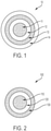
- FIG. 1 illustrates an example of a conventional light diffusing fiber.
- the LDF 10 includes a core portion 11 and a cladding 12 which surrounds and is in direct contact with the core portion 11.
- the LDF 10 also includes a scattering coating layer 13 which surrounds and is in direct contact with the cladding 12 and a separate phosphor coating layer 14 which surrounds the scattering coating layer 13. Because of the separate coating layers, such conventional LDF may have an outer diameter of greater than about 250 ⁇ m and commonly has an outer diameter of about 500 ⁇ m or greater.
- FIG. 2 illustrates an exemplary light diffusing fiber.
- the LDF 100 includes a core portion 110 having an outer radius of greater than about 10 ⁇ m and less than about 250 ⁇ m, for example, between about 25 ⁇ m and about 200 ⁇ m, or between about 30 ⁇ m and about 100 ⁇ m.
- the core portion 110 includes voids that scatter light propagating in the core portion 110 such that the light is directed radially outward from the core portion 110, thereby illuminating the LDF and the space surrounding the LDF.
- the scatter-induced attenuation may be increased through increasing the concentration of voids, positioning voids throughout the fiber, or in cases where the voids are limited to an annular ring, increasing the width of the void-containing ring will also increase the scattering-induced attenuation for the same density of voids. Additionally, in compositions where the voids are helical, the scattering-induced attenuation may also be increased by varying the pitch of the helical voids over the length of the fiber.
- the LDF 100 may further include a cladding 120 which surrounds and is in direct contact with the core portion 110.
- the cladding 120 may be formed from a material which has a relatively low refractive index in order to increase the numerical aperture (NA) of the LDF 100.
- the numerical aperture of the fiber may be greater than about 0.3, and in some embodiments greater than about 0.4.
- the cladding 120 may include a low index polymeric material such as UV or thermally curable fluoroacrylate, such as PC452 available from SSCP Co. Ltd 403-2, Moknae, Ansan, Kyunggi, Korea, or silicone.
- Such low index polymer cladding may have a relative refractive index that is negative relative to pure undoped silica.
- the relative refractive index of the low index polymer cladding may be less than about -0.5%, or even less than about -1.0%.
- the cladding 120 may include a high modulus coating.
- the cladding 120 may include a silica glass.
- the silica glass in the cladding may be down-doped with a down-dopant, such as, for example, fluorine.
- the term "down-dopant" refers to a dopant which has a propensity to lower the refractive index relative to pure undoped silica.
- the cladding 120 generally has an index of refraction which is less than the index of refraction of the core portion 110.
- the cladding 120 generally extends from the outer radius of the core portion 110.
- the radial width of the cladding 120 may be greater than about 1.0 ⁇ m.
- the radial width of the cladding 120 may be between about 5.0 ⁇ m and about 300 ⁇ m, such as less than about 200 ⁇ m.
- the radial width of the cladding 120 may also be, for example, between about 2.0 ⁇ m and about 100 ⁇ m, between about 2.0 ⁇ m and about 50 ⁇ m, between at least 2.0 ⁇ m and about 20 ⁇ m, or even between about 2.0 ⁇ m and about 12 ⁇ m.
- the radial width of the cladding 120 may be, for example, at least about 7.0 ⁇ m.
- the LDF 100 further includes an outer polymer coating layer 130 which surrounds and is in direct contact with the cladding 120.
- outer polymer coating layer is meant only to relate the position of the polymer coating layer to the light diffusing device and is not meant to designate the polymer coating as being the outermost coating layer of the coated light diffusing device. It should be understood that embodiments of the present disclosure contemplate coated light diffusing devices having one or more additional coatings, for example protective coatings, that surround the outer polymer coating layer 130.
- the LDF 100 may also include an optional coating between the cladding 120 and the outer polymer coating layer 130.
- the optional coating is a low modulus material that may be included to better protect the glass portions of the light-diffusing fiber by dissipating mechanical disturbances transmitted through the outer polymer coating layer 130 when the light-diffusing fiber is subjected to an external force.
- the optional coating surrounds and contacts the cladding 120.
- the optional coating is the cured product of a composition that includes a curable crosslinker, a curable diluent, and a polymerization initiator.
- the composition may include one or more curable crosslinkers, one or more curable diluents, and/or one or more polymerization initiators.
- the curable crosslinker is essentially free of urethane and urea functional groups.
- the optional coating has a lower refractive index than the outer polymer coating.
- the outer polymer coating 130 includes a scattering material and a luminophore.
- the outer polymer coating layer 130 may include a polymer material that may be any liquid polymer or prepolymer material into which a scattering composition (which includes the scattering material) and the luminophore could be added and in which the blend may be applied to the fiber as a liquid and then converted to a solid after application to the fiber.
- the outer polymer coating layer 130 is formed from a polymer material such as an acrylate-based polymer or silicone-based polymer.
- the scattering composition may be, for example, a dispersion which includes a scattering material and which is added to the liquid polymer blend.
- the concentration of the scattering composition in the liquid polymer blend of the outer polymer coating may be between about 5.0 wt. % and about 80 wt. %.
- the concentration of the scattering composition in the liquid polymer blend of the outer polymer coating may be between about 10 wt. % and about 70 wt. %, or between about 20 wt. % and about 60 wt. %, or even between about 30 wt. % and about 60 wt. %.
- the scattering material may include nano- or microparticles with an average diameter of from about 200 nm to about 10 ⁇ m.
- the average diameter of the particles may be between about 400 nm and about 8.0 ⁇ m, or even between about 100 nm and about 6.0 ⁇ m.
- the nano- or microparticles may be particles of a metal oxide or of other high refractive index materials, such as, but not limited to, TiO 2 , ZnO, SiO 2 , BaS, MgO, Al 2 O 3 or Zr.
- the scattering material may include TiO 2- based particles, and the scattering composition may be, for example, a white ink dispersion, which provides for an angle independent distribution of light scattered from the core portion 110 of the light diffusing optical fiber 100.
- the concentration of the particles of the scattering material may vary along the length of the fiber or may be constant and may be a weight percent sufficient to provide even scattering of the light while limiting overall attenuation.
- the concentration of the particles of the scattering material is between about 0.5 wt. % and about 10 wt. %, and may be between about 1.0 wt. % and about 10 wt. %, or between about 1.25 wt. % and about 7.5 wt. %, or between about 1.25 wt. % and about 6.0 wt. %, or between about 1.5 wt. % and about 10 wt. %, or between about 1.5 wt. % and about 7.5 wt.
- the scattering material may also include nano- or microsized particles or voids of low refractive index, such as gas bubbles.
- the luminophore may include a fluorescent or phosphorescent material which may be any organic or inorganic fluorescent or phosphorescent material or a mixture of any organic or inorganic fluorescent or phosphorescent materials.
- the luminophore may include, but is not limited to, Ce-doped YAG, Nd-doped YAG, rare earth oxide materials, quantum dots such as CdS, CdS/ZnS, InP, nanoparticles, metal-enhanced fluorescence of organic fluorophores, etc.
- the concentration of luminophore in the liquid polymer blend of the outer polymer coating may be controlled to provide desired color coordinates x and y in CIE color space diagram.
- the concentration of the luminophore in the liquid polymer blend of the outer polymer coating may be between about 10 wt. % and about 50 wt. %.
- the concentration of the luminophore in the liquid polymer blend of the outer polymer coating may be between about 15 wt. % and about 45 wt. %, or between about 25 wt. % and about 40 wt. %, or even between about 30 wt. % and about 35 wt. %.
- the outer polymer coating layer 130 generally extends from the outer radius of the cladding 120.
- the radial width of the outer polymer coating layer 130 may be between about 1.0 ⁇ m and about 450 ⁇ m, for example, between about 20 ⁇ m and about 300 ⁇ m, or even between about 40 ⁇ m and about 90 ⁇ m.
- the radial width of LDF designs according to embodiments of the present disclosure may be limited such that the outer diameter of the LDF is less than or equal to about 500 ⁇ m, or less than or equal to about 400 ⁇ m, or even less than or equal to about 300 ⁇ m.
- the outer polymer coating layer 130 includes both a scattering material and a luminophore
- the outer polymer coating layer 130 enhances the distribution and/or the nature of the light emitted radially from the core portion 110 and converts light emitted radially from the core portion 110 to a longer wavelength of light.
- the efficiency of the luminophore to convert light is known to be related to luminophore concentration and to the amount of the luminophore-containing material (i.e. thickness or volume of the material).
- excitation photon a photon which the excitation photon interacts with the luminophore.
- the number of interactions between the excitation photons and the luminophore is proportional to the concentration of the luminophore and the thickness of the luminophore-containing material. Typical conversion efficiency for a single interaction is greater than about 90%.
- luminophore concentration and/or thickness of luminophore-containing coatings are increased.
- LDF having greater than about 0 wt. % scattering material in the outer polymer coating layer 130 displayed a path length of the excitation photon that was greater than the actual thickness of the polymer coating layer 130.
- LDF having about 0.50 wt. % or greater of scattering material in the outer polymer coating layer 130 displayed a path length of the excitation photon that was greater than about 2.0 times the actual thickness of the polymer coating 130.
- Figure 3 shows a parallel section of the LDF 100 illustrated in Figure 2 .
- unscattered light propagates down the length of LDF 100 from the source in the direction shown by arrow 150.
- Scattered light shown by arrow 160, exits LDF 100 at an angle 170, where the angle 170 describes angular difference between the direction of the fiber and the direction of the scattered light when it leaves LDF 100.
- the UV-visible spectrum of LDF 100 may be independent of angle 170.
- the intensities of the spectra when angle 170 is between about 20° and about 150° are within ⁇ 40% as measured at the peak wavelength.
- the intensities of the spectra when angle 170 is between about 20° and about 150° may be within ⁇ 30%, or ⁇ 20%, or ⁇ 15%, or ⁇ 10%, or even ⁇ 5%, as measured at the peak wavelength.
- Colored light can be emitted from the LDF 100 having an outer polymer coating layer 130 in accordance with the present disclosure by coupling the LDF 100 with a higher energy (lower wavelength) light source, such as a light source emitting at 405 nm or 445 nm.
- the light source may be configured to emit light having a wavelength of between about 300 nm and about 550 nm.
- the light source may be, for example, a diode laser.
- the light from the light source is emitted from the core portion 110 and causes the luminophore to fluoresce or phosphoresce such that the wavelength of the light emitted from the LDF 100 corresponds to a predetermined color.
- the luminophore includes a mixture of fluorescent or phosphorescent materials, the mixture may be modified and controlled such that the wavelength of the light emitted from the LDF 100 corresponds to a predetermined color.
- colored light can be emitted from the LDF corresponding to the wavelengths of light used by plants in photosynthesis.
- chlorophyll-a utilizes light between 430 nm and 662 nm.
- Chlorophyll-b utilizes light between 453 nm and 642 nm.
- Carotenoids utilize light between 449 and 475 nm.
- the light source and the LDF are configured so that the LDF emits light at wavelengths between 430 nm and 662 nm.
- the presence of liquid or liquid media (which may contain colored pigments) inside the container may affect the passage of light through the container. Therefore, the user may need to adjust the wavelength of light delivered to the container depending upon the culture conditions inside the container to maximize the delivery of light at the appropriate wavelength to cells growing inside the container to reach desired cell growth results.
- the LDF and the light source can be configured to emit light useful to sterilize the container.
- UV light in the range of 200nm to 280 nm may be delivered to the container via the LDF.
- the light source may be, for example, a UV laser.
- a thicker diameter light source may be required, to provide a UV light source.
- the LDF may be flexible, or stiff.
- the LDF may be provided in bundles.
- the LDF affords a small, flexible light source that can be coupled to a laser or LED source.
- This small flexible fiber should be compatible with existing bioreactor systems.
- Such systems or containers may be vertical (see, for example, Figure 7A ), horizontal (see, for example, Figure 7B ), rigid or flexible.
- Red, green and blue light sources may be coupled together to afford light of almost any wavelength combination.
- the light source employed may be remote from the fiber and can be further removed by the use of transmission fiber. This allows the fiber to deliver light directly into an aqueous cell culture media contained in the container.
- the fiber remains cool, allowing the fiber to reside inside the container without affecting the temperature of the contents of the container. This also allows the fiber to reside in a wall of the container, or wrapped around the container.
- the fiber is coupled to a detector which measures transmission changes (changes in optical density) to monitor cell growth.
- a detector which measures transmission changes (changes in optical density) to monitor cell growth.
- multiple fibers could be used to illuminate the container.
- multiple fibers, enough to illuminate the entire container may be used.
- the core 110 can be made by any number of methods which incorporate voids or particles into the glass fiber.
- methods for forming an optical fiber preform with voids are described in, for example, U.S. Patent Application Publication No. 2007/0104437 A1 . Additional methods of forming voids may be found in, for example, U.S. Patent Application Publication No. 2011/0122646 A1 , U.S. Patent Application Publication No. 2012/0275180 A1 , and U.S. Patent Application Publication No. 2013/0088888 A1 .
- a method for forming a light diffusing fiber includes forming an optical fiber preform having a preform core portion. The method may further include drawing the optical fiber preform to form an optical fiber and coating the optical fiber with an outer polymer coating layer that includes a scattering material and a luminophore.
- the method may further include coating the optical fiber with a polymeric cladding layer that surrounds and is in direct contact with the core.
- coating the optical fiber with the outer polymer coating layer includes coating the cladding layer with the outer polymer coating layer.
- the optical fiber preform may further include a silica-based glass cladding portion surrounding and in direct contact with the preform core portion. Such optical fiber preform may be drawn to form an optical fiber having a silica-based glass cladding, and coating the optical fiber with the outer polymer coating layer includes coating the silica-based glass cladding with the outer polymer coating layer.
- the optical fiber is drawn from an optical fiber preform with a fiber take-up system and exits the draw furnace along a substantially vertical pathway.
- the fiber may be rotated as it is drawn to produce helical voids along the long axis of the fiber.
- a non-contact flaw detector may be used to examine the optical fiber for damage and/or flaws that may have occurred during the manufacture of the optical fiber. Thereafter, the diameter of the optical fiber may be measured with a non-contact sensor.
- the optical fiber may optionally be drawn through a cooling system which cools the optical fiber prior to the application of coatings to the optical fiber.
- the optical fiber After the optical fiber exits the draw furnace or optional cooling system, the optical fiber enters at least one coating system where one or more polymer layers are applied to the optical fiber. As the optical fiber exits the coating system, the diameter of the optical fiber may be measured with non-contact sensor. Thereafter, a non-contact flaw detector is used to examine the optical fiber for damage and/or flaws in the coating that may have occurred during the manufacture of the optical fiber.
- Table I illustrates characteristics and performance of various outer polymer coating layers in accordance with embodiments of the present disclosure.
- Light diffusing optical fibers 1-5 included outer polymer coating layers in accordance with the outer polymer coating layer 130 illustrated in Figure 3 .
- the outer polymer coating layer in each of fibers 1-5 was applied to an LDF that included a core portion, a cladding portion and a coating layer that was the cured product of a polymer material.
- light diffusing optical fibers 6-8 were conventional LDF including the various glass portions and polymer layers as the LDF illustrated in Figure 2 with the outermost coating being a phosphor coating layer 14.
- Table I shows concentration of scattering composition (wt. %), concentration of scattering material (wt.
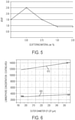
- Figure 4 is a graph showing the relationship of the improvement ratio of the path length of an excitation photon in the outermost coating layer to the concentration of scattering material (wt. %) in light diffusing fibers according to embodiments of the present disclosure. As shown, where the outermost coating layer has a concentration of scattering material of about 0.50 wt. % or more, the path length of an excitation photon is more than 2.0 times greater than the actual thickness of the outermost coating layer.
- Embodiments of the present disclosure provide LDF having reduced luminophore concentration in the coatings that emit light having the same color and the same or better uniformity as conventional LDF. Differences in the CIE 1931 x, y chromaticity space values for the color of the light emitted from light diffusing fibers at different viewing angles was observed and measured.
- Figure 5 is a graph showing the relationship of the ratio of change in the x chromaticity of CIE 1931 color space value/change in the y chromaticity of CIE 1931 color space value of the color of light emitted from the light diffusing fibers to the concentration of scattering material (wt. %) in the outermost coating layer. The lower the ratio, the better the uniformity of the color of the emitted light.
- the uniformity of the color of light emitted from the light diffusing fibers is the same or better than the conventional LDF having no scattering material in the outermost coating layer.
- Figure 6 is a graph showing the relationship of luminophore concentration in a luminophore-containing coating layer (illustrated with a value that is the result of luminophore concentration in the coating multiplied by the area of the coating) and the outer diameter of the LDF in two light diffusing fibers 610 and 620.
- the two fibers 610 and 620 were designed to emit light having a color that can be defined as 0.31:0.31 using CIE 1931 x, y chromaticity space values.
- Fibers 610 were conventional LDF, such as is illustrated in Figure 1 , having a phosphor coating layer 14 having a thickness of 120 ⁇ m.
- Fibers 620 were formed in accordance with the LDF illustrated in Figure 2 and had an outer polymer coating layer 130 having a thickness of 40 ⁇ m. As is shown, for all cladding outer diameters between 190 ⁇ m and 260 ⁇ m, fibers 620 emitted light having the same color as fibers 610 with a reduced luminophore concentration. In particular, luminophore concentration of fibers 620 was between about 3.5 and about 5.0 times less than luminophore concentration of fibers 610.
- Figures 7 A-C are illustrations of embodiments of illuminated containers for the growth of biological entities.
- the container may be rigid or flexible and may be in the form of a single well, a single well of a multi-well plate, a flask, a dish, a bag, a tank, a multi-layered flask, a bioreactor or a bioreactor.
- the container may be reusable or single-use.
- the container may have at least one wall 220.
- the at least one wall 220 may be rigid or flexible. That is, the wall 220 may be the side of a bag or, as is shown in, for example, FIG. 7A , a single wall 220 of a cylindrical container.
- the container may have more than one wall 220 to form any suitable shape including square, cuboid, pyramidal, or any other shape.
- Any polymer such as polystyrene, polycarbonate, acrylic, polystyrene, or polyester
- suitable for molding and commonly utilized in the manufacture of laboratory ware may be used.
- polystyrene is used.
- Separate parts, including multiple walls, may be assembled by any number of methods including but not limited to: adhesive or solvent bonding, heat sealing or welding, compression, ultrasonic welding, laser welding and/or any other method commonly used for generating seals between parts such that it becomes an integral portion of the interior surface of the container.
- the container may have at least one port, or one access feature for delivering biological entities (optionally including media or water or other materials used when growing biological entities) to the container or removing biological entities from the container.
- biological entities optionally including media or water or other materials used when growing biological entities
- a cylindrical container 200 is illustrated, with an LDF 201 inserted into the container 200 through a port 203 in the container.
- the LDF 201 is illustrated as a solid line outside the container, and a dashed line inside the container.
- the container may be of any size or shape.
- the container may have additional ports for the entry and exit of cells and media, and may be rigid or flexible.
- Figure 7B is an illustration of a flexible bag 205 for the growth of biological entities having an LDF 201 inside the bag.
- Figure 7C is an illustration of a flexible bag 205 embodiment having an LDF 201 wrapped around the outside of the bag.
- the bag would need to be transparent in order for the light diffusing from the fiber to reach cells inside the bag.
- the bag 205, or the flexible container may be made from polymeric material.
- the bag is made of layers of polymeric material.
- the inside layer, the layer in contact with the contents of the bag may be made from a material having low leachables and extractables, low cytotoxicity, low cell binding characteristics, resistance to chemical damage, and good water tight characteristics.
- Example materials are low density polyethylene (LDPE) or polypropylene (PP).
- LDPE low density polyethylene
- PP polypropylene
- a second layer provides gas permeability and flexibility.
- Example materials are polyvinyl alcohol (PVA) or polyvinyl chloride (PVC). An outer layer may be used to lend mechanical strength.
- Example materials are low density polyethylene (LDPE) or polyethylene terephthalate (PET). such as, for example, polypropylene, ethyl vinyl acetate, polyvinyl acetate. While these material examples are provided, those of ordinary skill in the art will recognize that any suitable material may be used.
- Figure 8 A-C illustrates an embodiment of a container where the light diffusing fiber is embedded within a wall 220 of a container.
- an LDF 201 is placed on a sheet of polymer 210.
- the sheet of polymer is folded around the LDF and melted or welded together.
- a container in this case a flexible bag, is shown, made from the polymer 201 containing the embedded LDF 201.
- additional layers of polymer may be melt pressed or welded together with the polymer having embedded LDF to form multiple layered containers.
- Light might escape from the distal end of the LDF. This emitted light is coupled to a detector to measure loss of light during transmission through the media in the container, and thus measure optical density to determine cell growth within the container.
- the container of aspect (1) is provided, wherein the light diffusing fiber is flexible.
- the container of any of aspects (1)-(2) is provided, wherein the container is a well, a flask, a dish, a bag, a tank, a multi-layered flask, a bioreactor or a single use bioreactor.
- the container of any of aspects (1)-(3) is provided, wherein the light diffusing fiber is configured to deliver light having a wavelength in a range between 430 nm and 662 nm.
- the container of any of aspects (1)-(4) is provided, wherein the light diffusing fiber is configured to deliver light having a wavelength in a range between 200nm to 280 nm.
- the container of any of aspects (1)-(5) is provided, wherein the light diffusing fiber is contained within the container.
- the container of aspect (6) is provided, wherein the light diffusing fiber is immersed into an aqueous cell culture media contained in the container.
- the container of any of aspects (1)-(4) is provided, wherein the light diffusing fiber is on the outside of the container.
- the container of any of aspects (1)-(4) is provided, wherein the light diffusing fiber is imbedded in a wall of the container.
- the container of any of aspects (1)-(9) wherein the outer polymer coating layer of the light diffusing fiber comprises a radial width of between about 1.0 ⁇ m and about 450 ⁇ m.
- the container of any of aspects (1)-(10) is provided, wherein the light diffusing fiber of comprises an outer diameter of less than or equal to about 250 ⁇ m.
- the container of any of aspects (1)-(11) is provided, wherein the scattering material comprises high refractive index materials.
- the container of aspect (12) is provided, wherein the high refractive index materials comprise metal oxide particles.
- the container of aspect (13) is provided, wherein the metal oxide particles are selected from the group consisting of particles of TiO2, ZnO, SiO2, BaS, MgO, Al2O3 and Zr.
- the container of aspect (13) is provided, wherein the metal oxide particles comprise particles of TiO2.
- the container of any of aspects (1)-(15) wherein the liquid polymer blend comprises between about 0.5 wt. % and about 10 wt. % of the scattering material.
- the container of any of aspects (1)-(16) is provided, wherein the luminophore is selected from the group consisting of a fluorescent material, a phosphorescent material, and mixtures thereof.
- the container of any of aspects (1)-(17) wherein the luminophore is selected from the group consisting of Ce-doped YAG, Nd-doped YAG, rare earth oxide materials, quantum dots, nanoparticles, and metal-enhanced fluorescence of organic fluorophores.
- the container of any of aspects (1)-(18) is provided, wherein the liquid polymer blend comprises between about 10 wt. % and about 50 wt. % of the luminophore.
- the container of any of aspects (1)-(19) is provided, wherein the core of the light diffusing fiber comprises nano-sized structures.
- the container of aspect (20) is provided, wherein the nano-sized structures comprise gas-filled voids.
- the container of aspect (21) is provided, wherein the gas-filled voids are filled with a gas selected from the group of SO2, Kr, Ar, CO2, N2, O2 and mixture thereof.
- the container of aspect (20) is provided, wherein the nano-sized structures have a diameter of about 10 nm to about 1.0 ⁇ m.
Description
- The present disclosure relates generally to light diffusing optical fiber for use in illumination applications such as the growth of biological entities, and, more particularly, to light diffusing optical fiber having color converting coatings.
- Optical fiber that emit light radially outward along the length of the fiber, thereby illuminating the fiber, are particularly useful for a wide array of applications, such as special lighting, photochemistry, and for use in electronics and display devices. Such light diffusing fiber (referred to herein as "LDF") have been used to successfully demonstrate the emission of light of various colors. Light sources capable of emitting electromagnetic radiation that is in the visible light range of wavelengths may be coupled to the LDF to introduce light having different colors into the LDF. Such colored light is then emitted along the length of the LDF. However, light sources capable of emitting light of certain colors can be expensive and can make their use cost prohibitive in many LDF applications.
- As an alternative, a luminophore (an atom or chemical compound that manifests luminescence, and includes a variety of fluorophores and phosphors) may be disposed on a surface of the LDF. Often, a coating layer including the luminophore is disposed on a surface of the LDF surrounding one more other coating layers. Electromagnetic radiation emitted from a light source at a first wavelength may interact with the luminophore and be converted to a second wavelength in the visible light range of wavelengths. Similar to the previous discussion, the light source may be chosen based on the wavelength of the light emitted from the light source. Additionally, the luminophore may be chosen based on the intended wavelength of the light emitted along the length of the LDF. In this manner, light having a predetermined color may be emitted along the length of the LDF. However, luminophore materials used for this purpose can be difficult to mix with coating polymers in high concentrations. As a result, it is conventionally necessary for the coating having the luminophore materials to be thick enough to enable adequate light conversion. For example, where conventional LDF has an outer diameter of about 250 µm, the thickness added by a coating including a luminophore may increase the LDF outer diameter to about 500 µm or greater. Such luminophore materials are conventionally expensive and forming coatings thick enough to enable adequate light conversion can be cost prohibitive in LDF applications where low costs are expected.
- Bioreactors are used to grow cells. Mammalian cells are grown in bioreactors to produce quantities of cells, proteins or other products. Non-mammalian cells are grown in bioreactors, in some instances to produce products including alcohol and biofuels. In some instances, non-mammalian cells require light as a part of their growth and culture. Efficient, economical and reliable light sources in bioreactors may be desirable.
-
US 2011/122646 A1 andUS 2013/090402 A1 disclose illumination systems. - According to a first aspect, there is provided an illuminate container as defined in claim 1.
- According to an embodiment, the light diffusing fiber, provided in a container for the growth of biological entities may be a fiber that is tunable to provide a desired wavelength of light. In embodiments, the wavelength of light is tuned to maximize the biological processes of the cells in culture in the container.
- In another embodiment, the light may be delivered directly to aqueous media contained in a container for the growth of biological entities.
- Additional features and advantages will be set forth in the detailed description which follows, and in part will be readily apparent to those skilled in the art from that description or recognized by practicing the embodiments as described herein, including the detailed description which follows, the claims, as well as the appended drawings.
- It is to be understood that both the foregoing general description and the following detailed description are merely exemplary, and are intended to provide an overview or framework to understanding the nature and character of the claims. The accompanying drawings are included to provide a further understanding, and are incorporated in and constitute a part of this specification. The drawings illustrate one or more embodiment(s), and together with the description serve to explain principles and operation of the various embodiments.
- The disclosure will be understood more clearly from the following description and from the accompanying figures, given purely by way of non-limiting example, in which:
-
Figure 1 illustrates a cross section of a conventional LDF; -
Figure 2 illustrates a cross section of an LDF in accordance with the present disclosure; -
Figure 3 illustrates a parallel section of an LDF in accordance with the present disclosure; -
Figure 4 is a graph showing the relationship of the improvement ratio of the path length of an excitation photon in a phosphor coating layer to the concentration of scattering material in light diffusing fibers according to embodiments of the present disclosure; -
Figure 5 is a graph showing the relationship of the ratio of change in the x chromaticity of CIE 1931 color space value/change in the y chromaticity of CIE 1931 color space value of the color of light emitted from the light diffusing fibers to the concentration of scattering material (wt. %) in the outermost coating layer; -
Figure 6 is a graph showing the relationship of luminophore concentration in a luminophore-containing coating layer and the outer diameter of the cladding layer in two light diffusing fibers; -
Figures 7A-C are drawings showing embodiments of deployment of LDF inside (Figure 7A and 7B ) and around (Figure 7C ) a container for the growth of biological entities; and -
Figures 8A-C are drawings showing lamination of a LDF in a layer of polymer which forms a container for the growth of biological entities. - Reference will now be made in detail to the present embodiment(s), an example(s) of which is/are illustrated in the accompanying drawings. Whenever possible, the same reference numerals will be used throughout the drawings to refer to the same or like parts.
- The singular forms "a," "an" and "the" include plural referents unless the context clearly dictates otherwise. The endpoints of all ranges reciting the same characteristic are independently combinable and inclusive of the recited endpoint.
- The present disclosure is described below, at first generally, then in detail on the basis of several exemplary embodiments. The features shown in combination with one another in the individual exemplary embodiments do not all have to be realized. In particular, individual features may also be omitted or combined in some other way with other features shown of the same exemplary embodiment or else of other exemplary embodiments.
- The term "light diffusing fiber" (LDF) refers to a flexible optical waveguide, such as an optical fiber, employing nano-sized structures that are utilized to scatter or diffuse light out of the sides of the fiber, such that light is guided away from the core of the waveguide and through the outer surfaces of the waveguide to provide illumination. Concepts relevant to the underlying principles of the claimed subject matter are disclosed in U.S. Patent Application Publication No.
US 2011/0122646 A1 . - As used herein, the term "nano-structured fiber region" describes a region or area of a fiber with a large number of gas filled voids, or other nano-sized structures. The region or area may have, for example, more than 50 voids, or more than 100 voids, or even more than 200 voids in the cross-section of the fiber. The gas filled voids may contain, for example, SO2, Kr, Ar, CO2, N2, O2, or mixture thereof. The cross-sectional size (e.g., diameter) of nano-sized structures (e.g., voids) as described herein may vary from about 10 nm to about 1.0 µm (for example, from about 50 nm to about 500 nm), and the length may vary from about 1.0 millimeter to about 50 meters (for example, from about 2.0 mm to about 5.0 meters, or from about 5.0 mm to about 1.0 meter).
- LDF as described has good angular scattering properties (uniform dissipation of light away from the axis of the fiber) and good bending performance to avoid bright spots at fiber bends. A desirable attribute of at least some of the embodiments described herein is uniform and high illumination along the length of the fiber. Because the optical fiber is flexible, it allows a wide variety of the shapes to be deployed. The LDF described herein may have no bright spots (due to elevated bend losses) at the bending points of the fiber, such that the illumination provided by the fiber does not vary by more than about 40%. The variation of the illumination provided by the fiber may be less than about 30%, or less than about 20% or even less than about 10%. For example, in at least some embodiments, the average scattering loss of the fiber is greater than about 50 dB/km, and the scattering loss does not vary by more than about 40% (i.e., the scattering loss is within ±40% of the average scattering loss) over any given fiber segment having a length of about 0.2 meters. The average scattering loss of the fiber may be greater than about 50 dB/km with the scattering loss varying by less than about 40% over fiber segments having a length of less than about 0.05 meters. The average scattering loss of the fiber may be greater than about 50 dB/km with the scattering loss varying by less than about 40% over fiber segments having a length of about 0.01 meters. The average scattering loss of the fiber may also be greater than about 50 dB/km with the scattering loss varying by less than about 30%, or less than 20%, or even less than about 10%, over fiber segments having a length of about 0.01 meters.
- According to embodiments of the present disclosure, the intensity variation of the integrated light intensity diffused through sides of the fiber at the illumination wavelength is less than about 40% for the target length of the fiber, which can be, for example, between about 0.02 meters to about 100 meters. The light diffusing fiber described herein may produce uniform illumination along the entire length of the fiber or uniform illumination along a segment of the fiber which is less than the entire length of the fiber. As used herein, the term "uniform illumination," means that the intensity of light emitted from the light diffusing fiber does not vary by more than 25% over the specified length.
- LDF designs described herein include a nano-structured fiber region (region with nano-sized structures) placed in the core area of the fiber, or very close to the core. The LDF have scattering losses in excess of about 50 dB/km, for example, greater than about 100 dB/km, greater than about 200 dB/km, greater than about 300 dB/km, greater than about 325 dB/km, greater than about 500 dB/km, greater than about 1000 dB/km, greater than about 3000 dB/km, or even greater than about 5000 dB/km. The scattering loss, and thus illumination, or light radiated by the fiber, is uniform in angular space.
- In order to reduce or to eliminate bright spots at bends in the fiber, it is desirable that the increase in attenuation at a 90° bend in the fiber is less than about 5.0 dB/turn, for example, less than about 3.0 dB/turn, less than about 2.0 dB/turn, or even less than about 1.0 dB/turn when the bend diameter is less than about 50 mm. In exemplary embodiments, these low bend losses are achieved at even smaller bend diameters, for example, at bend diameters of less than about 20 mm, less than about 10 mm, or even less than about 5.0 mm. The total increase in attenuation may be less than about 1.0 dB per 90 degree turn at a bend radius of about 5.0 mm
- The bending loss is equal to or is less than the intrinsic scattering loss from the core of the straight fiber. The intrinsic scattering is predominantly due to scattering from the nano-sized structures. Thus, according to at least the bend insensitive embodiments of optical fiber, the bend loss does not exceed the intrinsic scattering of the fiber. However, because scattering level is a function of bending diameter, the bending deployment of the fiber depends on its scattering level. For example, the fiber may have a bend loss of less than about 3.0 dB/turn, or even less than about 2.0 dB/turn, and the fiber can be bent in an arc with a radius as small as about 5.0 mm without forming bright spots.
-
Figure 1 illustrates an example of a conventional light diffusing fiber. As shown, theLDF 10 includes a core portion 11 and acladding 12 which surrounds and is in direct contact with the core portion 11. TheLDF 10 also includes ascattering coating layer 13 which surrounds and is in direct contact with thecladding 12 and a separatephosphor coating layer 14 which surrounds thescattering coating layer 13. Because of the separate coating layers, such conventional LDF may have an outer diameter of greater than about 250 µm and commonly has an outer diameter of about 500 µm or greater. -
Figure 2 illustrates an exemplary light diffusing fiber. TheLDF 100 includes acore portion 110 having an outer radius of greater than about 10 µm and less than about 250 µm, for example, between about 25 µm and about 200 µm, or between about 30 µm and about 100 µm. According to embodiments of the present disclosure, thecore portion 110 includes voids that scatter light propagating in thecore portion 110 such that the light is directed radially outward from thecore portion 110, thereby illuminating the LDF and the space surrounding the LDF. The scatter-induced attenuation may be increased through increasing the concentration of voids, positioning voids throughout the fiber, or in cases where the voids are limited to an annular ring, increasing the width of the void-containing ring will also increase the scattering-induced attenuation for the same density of voids. Additionally, in compositions where the voids are helical, the scattering-induced attenuation may also be increased by varying the pitch of the helical voids over the length of the fiber. - Still referring to
Figure 2 , theLDF 100 may further include acladding 120 which surrounds and is in direct contact with thecore portion 110. Thecladding 120 may be formed from a material which has a relatively low refractive index in order to increase the numerical aperture (NA) of theLDF 100. The numerical aperture of the fiber may be greater than about 0.3, and in some embodiments greater than about 0.4. Thecladding 120 may include a low index polymeric material such as UV or thermally curable fluoroacrylate, such as PC452 available from SSCP Co. Ltd 403-2, Moknae, Ansan, Kyunggi, Korea, or silicone. Such low index polymer cladding may have a relative refractive index that is negative relative to pure undoped silica. For example, the relative refractive index of the low index polymer cladding may be less than about -0.5%, or even less than about -1.0%. Also, thecladding 120 may include a high modulus coating. Alternatively, thecladding 120 may include a silica glass. According to embodiments of the present disclosure, the silica glass in the cladding may be down-doped with a down-dopant, such as, for example, fluorine. As used herein, the term "down-dopant" refers to a dopant which has a propensity to lower the refractive index relative to pure undoped silica. Thecladding 120 generally has an index of refraction which is less than the index of refraction of thecore portion 110. - The
cladding 120 generally extends from the outer radius of thecore portion 110. The radial width of thecladding 120 may be greater than about 1.0 µm. For example, the radial width of thecladding 120 may be between about 5.0 µm and about 300 µm, such as less than about 200 µm. The radial width of thecladding 120 may also be, for example, between about 2.0 µm and about 100 µm, between about 2.0 µm and about 50 µm, between at least 2.0 µm and about 20 µm, or even between about 2.0 µm and about 12 µm. The radial width of thecladding 120 may be, for example, at least about 7.0 µm. - Referring again to
Figure 2 , theLDF 100 further includes an outerpolymer coating layer 130 which surrounds and is in direct contact with thecladding 120. As used herein, the term "outer polymer coating layer" is meant only to relate the position of the polymer coating layer to the light diffusing device and is not meant to designate the polymer coating as being the outermost coating layer of the coated light diffusing device. It should be understood that embodiments of the present disclosure contemplate coated light diffusing devices having one or more additional coatings, for example protective coatings, that surround the outerpolymer coating layer 130. TheLDF 100 may also include an optional coating between thecladding 120 and the outerpolymer coating layer 130. The optional coating is a low modulus material that may be included to better protect the glass portions of the light-diffusing fiber by dissipating mechanical disturbances transmitted through the outerpolymer coating layer 130 when the light-diffusing fiber is subjected to an external force. When present, the optional coating surrounds and contacts thecladding 120. In one embodiment, the optional coating is the cured product of a composition that includes a curable crosslinker, a curable diluent, and a polymerization initiator. The composition may include one or more curable crosslinkers, one or more curable diluents, and/or one or more polymerization initiators. In one embodiment, the curable crosslinker is essentially free of urethane and urea functional groups. When present, the optional coating has a lower refractive index than the outer polymer coating. - The
outer polymer coating 130 includes a scattering material and a luminophore. The outerpolymer coating layer 130 may include a polymer material that may be any liquid polymer or prepolymer material into which a scattering composition (which includes the scattering material) and the luminophore could be added and in which the blend may be applied to the fiber as a liquid and then converted to a solid after application to the fiber. In some embodiments, the outerpolymer coating layer 130 is formed from a polymer material such as an acrylate-based polymer or silicone-based polymer. - The scattering composition may be, for example, a dispersion which includes a scattering material and which is added to the liquid polymer blend. The concentration of the scattering composition in the liquid polymer blend of the outer polymer coating may be between about 5.0 wt. % and about 80 wt. %. For example, the concentration of the scattering composition in the liquid polymer blend of the outer polymer coating may be between about 10 wt. % and about 70 wt. %, or between about 20 wt. % and about 60 wt. %, or even between about 30 wt. % and about 60 wt. %.
- The scattering material may include nano- or microparticles with an average diameter of from about 200 nm to about 10 µm. For example, the average diameter of the particles may be between about 400 nm and about 8.0 µm, or even between about 100 nm and about 6.0 µm. The nano- or microparticles may be particles of a metal oxide or of other high refractive index materials, such as, but not limited to, TiO2, ZnO, SiO2, BaS, MgO, Al2O3 or Zr. The scattering material may include TiO2-based particles, and the scattering composition may be, for example, a white ink dispersion, which provides for an angle independent distribution of light scattered from the
core portion 110 of the light diffusingoptical fiber 100. The concentration of the particles of the scattering material may vary along the length of the fiber or may be constant and may be a weight percent sufficient to provide even scattering of the light while limiting overall attenuation. The concentration of the particles of the scattering material is between about 0.5 wt. % and about 10 wt. %, and may be between about 1.0 wt. % and about 10 wt. %, or between about 1.25 wt. % and about 7.5 wt. %, or between about 1.25 wt. % and about 6.0 wt. %, or between about 1.5 wt. % and about 10 wt. %, or between about 1.5 wt. % and about 7.5 wt. %, or between about 1.5 wt. % and about 6.0 wt. %, or between about 2.0 wt. % and about 10 wt. %, or between about 2.0 wt. % and about 7.5 wt. %, or even between about 2.0 wt. % and about 6.0 wt. %. The scattering material may also include nano- or microsized particles or voids of low refractive index, such as gas bubbles. - The luminophore may include a fluorescent or phosphorescent material which may be any organic or inorganic fluorescent or phosphorescent material or a mixture of any organic or inorganic fluorescent or phosphorescent materials. For example, the luminophore may include, but is not limited to, Ce-doped YAG, Nd-doped YAG, rare earth oxide materials, quantum dots such as CdS, CdS/ZnS, InP, nanoparticles, metal-enhanced fluorescence of organic fluorophores, etc. The concentration of luminophore in the liquid polymer blend of the outer polymer coating may be controlled to provide desired color coordinates x and y in CIE color space diagram. The concentration of the luminophore in the liquid polymer blend of the outer polymer coating may be between about 10 wt. % and about 50 wt. %. For example, the concentration of the luminophore in the liquid polymer blend of the outer polymer coating may be between about 15 wt. % and about 45 wt. %, or between about 25 wt. % and about 40 wt. %, or even between about 30 wt. % and about 35 wt. %.
- The outer
polymer coating layer 130 generally extends from the outer radius of thecladding 120. The radial width of the outerpolymer coating layer 130 may be between about 1.0 µm and about 450 µm, for example, between about 20 µm and about 300 µm, or even between about 40 µm and about 90 µm. The radial width of LDF designs according to embodiments of the present disclosure may be limited such that the outer diameter of the LDF is less than or equal to about 500 µm, or less than or equal to about 400 µm, or even less than or equal to about 300 µm. - Because the outer
polymer coating layer 130 includes both a scattering material and a luminophore, the outerpolymer coating layer 130 enhances the distribution and/or the nature of the light emitted radially from thecore portion 110 and converts light emitted radially from thecore portion 110 to a longer wavelength of light. The efficiency of the luminophore to convert light is known to be related to luminophore concentration and to the amount of the luminophore-containing material (i.e. thickness or volume of the material). Generally, promotion of an electron to a higher energy level, or excitation, occurs upon absorption of a photon (an "excitation photon"), and adequate light conversion is related to the period of time (i.e.: the number of interactions between the excitation photon and the luminophore) which the excitation photon interacts with the luminophore. As such, the number of interactions between the excitation photons and the luminophore is proportional to the concentration of the luminophore and the thickness of the luminophore-containing material. Typical conversion efficiency for a single interaction is greater than about 90%. Conventionally, to enable adequate light conversion in light diffusing optical fiber, luminophore concentration and/or thickness of luminophore-containing coatings are increased. However, because it can be difficult to mix high luminophore concentrations with coating polymers, enabling adequate light conversion is conventionally achieved by increasing the thickness of luminophore-containing coatings on the fiber. Without wishing to be limited by any particular theory, it is believed that including both a scattering material and a luminophore in the same coating layer increases the path length of the excitation photon independently of coating thickness, which in turn effectively reduces the thickness of the coating layer. LDF having greater than about 0 wt. % scattering material in the outerpolymer coating layer 130 displayed a path length of the excitation photon that was greater than the actual thickness of thepolymer coating layer 130. In particular, LDF having about 0.50 wt. % or greater of scattering material in the outerpolymer coating layer 130 displayed a path length of the excitation photon that was greater than about 2.0 times the actual thickness of thepolymer coating 130. -
Figure 3 shows a parallel section of theLDF 100 illustrated inFigure 2 . As shown, unscattered light propagates down the length ofLDF 100 from the source in the direction shown byarrow 150. Scattered light, shown byarrow 160, exitsLDF 100 at anangle 170, where theangle 170 describes angular difference between the direction of the fiber and the direction of the scattered light when it leavesLDF 100. The UV-visible spectrum ofLDF 100 may be independent ofangle 170. Alternatively, the intensities of the spectra whenangle 170 is between about 20° and about 150° are within ±40% as measured at the peak wavelength. For example, the intensities of the spectra whenangle 170 is between about 20° and about 150° may be within ±30%, or ±20%, or ±15%, or ±10%, or even ±5%, as measured at the peak wavelength. - Colored light can be emitted from the
LDF 100 having an outerpolymer coating layer 130 in accordance with the present disclosure by coupling theLDF 100 with a higher energy (lower wavelength) light source, such as a light source emitting at 405 nm or 445 nm. The light source may be configured to emit light having a wavelength of between about 300 nm and about 550 nm. The light source may be, for example, a diode laser. The light from the light source is emitted from thecore portion 110 and causes the luminophore to fluoresce or phosphoresce such that the wavelength of the light emitted from theLDF 100 corresponds to a predetermined color. Where the luminophore includes a mixture of fluorescent or phosphorescent materials, the mixture may be modified and controlled such that the wavelength of the light emitted from theLDF 100 corresponds to a predetermined color. - In embodiments, colored light can be emitted from the LDF corresponding to the wavelengths of light used by plants in photosynthesis. For example chlorophyll-a utilizes light between 430 nm and 662 nm. Chlorophyll-b utilizes light between 453 nm and 642 nm. Carotenoids utilize light between 449 and 475 nm. In embodiments, the light source and the LDF are configured so that the LDF emits light at wavelengths between 430 nm and 662 nm. The presence of liquid or liquid media (which may contain colored pigments) inside the container may affect the passage of light through the container. Therefore, the user may need to adjust the wavelength of light delivered to the container depending upon the culture conditions inside the container to maximize the delivery of light at the appropriate wavelength to cells growing inside the container to reach desired cell growth results.
- In additional embodiments, the LDF and the light source can be configured to emit light useful to sterilize the container. UV light, in the range of 200nm to 280 nm may be delivered to the container via the LDF. In these embodiments the light source may be, for example, a UV laser. In such embodiments, a thicker diameter light source may be required, to provide a UV light source.
- In embodiments, the LDF may be flexible, or stiff. For example, in embodiments, the LDF may be provided in bundles. The LDF affords a small, flexible light source that can be coupled to a laser or LED source. This small flexible fiber should be compatible with existing bioreactor systems. Such systems or containers may be vertical (see, for example,
Figure 7A ), horizontal (see, for example,Figure 7B ), rigid or flexible. Red, green and blue light sources may be coupled together to afford light of almost any wavelength combination. The light source employed may be remote from the fiber and can be further removed by the use of transmission fiber. This allows the fiber to deliver light directly into an aqueous cell culture media contained in the container. Because the light source is the only source of heat and may be remote from the container, the fiber remains cool, allowing the fiber to reside inside the container without affecting the temperature of the contents of the container. This also allows the fiber to reside in a wall of the container, or wrapped around the container. - The fiber is coupled to a detector which measures transmission changes (changes in optical density) to monitor cell growth. In embodiments, multiple fibers could be used to illuminate the container. In additional embodiments, multiple fibers, enough to illuminate the entire container may be used.
- The fibers described herein may be formed utilizing various techniques. For example, the
core 110 can be made by any number of methods which incorporate voids or particles into the glass fiber. For example, methods for forming an optical fiber preform with voids are described in, for example,U.S. Patent Application Publication No. 2007/0104437 A1 . Additional methods of forming voids may be found in, for example,U.S. Patent Application Publication No. 2011/0122646 A1 ,U.S. Patent Application Publication No. 2012/0275180 A1 , andU.S. Patent Application Publication No. 2013/0088888 A1 . - According to embodiments of the present disclosure, a method for forming a light diffusing fiber includes forming an optical fiber preform having a preform core portion. The method may further include drawing the optical fiber preform to form an optical fiber and coating the optical fiber with an outer polymer coating layer that includes a scattering material and a luminophore.
- The method may further include coating the optical fiber with a polymeric cladding layer that surrounds and is in direct contact with the core. Where the optical fiber is coated with a polymeric cladding layer, coating the optical fiber with the outer polymer coating layer includes coating the cladding layer with the outer polymer coating layer. Alternatively, the optical fiber preform may further include a silica-based glass cladding portion surrounding and in direct contact with the preform core portion. Such optical fiber preform may be drawn to form an optical fiber having a silica-based glass cladding, and coating the optical fiber with the outer polymer coating layer includes coating the silica-based glass cladding with the outer polymer coating layer.
- Generally, the optical fiber is drawn from an optical fiber preform with a fiber take-up system and exits the draw furnace along a substantially vertical pathway. The fiber may be rotated as it is drawn to produce helical voids along the long axis of the fiber. As the optical fiber exits the draw furnace, a non-contact flaw detector may be used to examine the optical fiber for damage and/or flaws that may have occurred during the manufacture of the optical fiber. Thereafter, the diameter of the optical fiber may be measured with a non-contact sensor. As the optical fiber is drawn along the vertical pathway, the optical fiber may optionally be drawn through a cooling system which cools the optical fiber prior to the application of coatings to the optical fiber. After the optical fiber exits the draw furnace or optional cooling system, the optical fiber enters at least one coating system where one or more polymer layers are applied to the optical fiber. As the optical fiber exits the coating system, the diameter of the optical fiber may be measured with non-contact sensor. Thereafter, a non-contact flaw detector is used to examine the optical fiber for damage and/or flaws in the coating that may have occurred during the manufacture of the optical fiber.
- Embodiments of the present disclosure are further described below with respect to certain exemplary and specific embodiments thereof, which are illustrative only and not intended to be limiting.
- Table I illustrates characteristics and performance of various outer polymer coating layers in accordance with embodiments of the present disclosure. Light diffusing optical fibers 1-5 included outer polymer coating layers in accordance with the outer
polymer coating layer 130 illustrated inFigure 3 . The outer polymer coating layer in each of fibers 1-5 was applied to an LDF that included a core portion, a cladding portion and a coating layer that was the cured product of a polymer material. As a comparison, light diffusing optical fibers 6-8 were conventional LDF including the various glass portions and polymer layers as the LDF illustrated inFigure 2 with the outermost coating being aphosphor coating layer 14. For the outermost coating layer of each of the fibers, Table I shows concentration of scattering composition (wt. %), concentration of scattering material (wt. %) and concentration of luminophore (wt. %), in the liquid polymer blend. Table I shows the concentration of polymer material (wt. %) in the scattering composition and also the coating thickness (µm) of the cured coating layer. Table I also shows CIE 1931 x, y chromaticity space values for the color of the light emitted from each of the fibers.TABLE I Scattering Composition (wt. %) Luminophore (wt. %) Polymer Material (wt. %) Scattering Material (wt. %) Thickness (µm) x y 1 15 28 57 0.75 90 0.365 0.445 2 15 28 57 0.75 140 0.39 0.49 3 10 30 60 0.50 90 0.345 0.405 4 30 23 47 1.50 90 0.31 0.34 5 40 20 40 2.00 50 0.28 0.25 6 0 33 67 0 25 0.27 0.23 7 0 33 67 0 100 0.3 0.3 8 0 33 67 0 190 0.36 0.41 - From the data in Table I, the path length of an excitation photon in the outermost coating layer was estimated and compared to the actual thickness of the outermost coating layer.
Figure 4 is a graph showing the relationship of the improvement ratio of the path length of an excitation photon in the outermost coating layer to the concentration of scattering material (wt. %) in light diffusing fibers according to embodiments of the present disclosure. As shown, where the outermost coating layer has a concentration of scattering material of about 0.50 wt. % or more, the path length of an excitation photon is more than 2.0 times greater than the actual thickness of the outermost coating layer. - Embodiments of the present disclosure provide LDF having reduced luminophore concentration in the coatings that emit light having the same color and the same or better uniformity as conventional LDF. Differences in the CIE 1931 x, y chromaticity space values for the color of the light emitted from light diffusing fibers at different viewing angles was observed and measured.
Figure 5 is a graph showing the relationship of the ratio of change in the x chromaticity of CIE 1931 color space value/change in the y chromaticity of CIE 1931 color space value of the color of light emitted from the light diffusing fibers to the concentration of scattering material (wt. %) in the outermost coating layer. The lower the ratio, the better the uniformity of the color of the emitted light. As shown, where the outermost coating layer has a concentration of scattering material of about 0.50 wt. % or more, the uniformity of the color of light emitted from the light diffusing fibers is the same or better than the conventional LDF having no scattering material in the outermost coating layer. - As less luminophore is needed in the outer polymer coating of LDF as described herein, the overall costs of the LDF are reduced.
Figure 6 is a graph showing the relationship of luminophore concentration in a luminophore-containing coating layer (illustrated with a value that is the result of luminophore concentration in the coating multiplied by the area of the coating) and the outer diameter of the LDF in twolight diffusing fibers fibers Fibers 610 were conventional LDF, such as is illustrated inFigure 1 , having aphosphor coating layer 14 having a thickness of 120 µm.Fibers 620 were formed in accordance with the LDF illustrated inFigure 2 and had an outerpolymer coating layer 130 having a thickness of 40 µm. As is shown, for all cladding outer diameters between 190 µm and 260 µm,fibers 620 emitted light having the same color asfibers 610 with a reduced luminophore concentration. In particular, luminophore concentration offibers 620 was between about 3.5 and about 5.0 times less than luminophore concentration offibers 610. -
Figures 7 A-C are illustrations of embodiments of illuminated containers for the growth of biological entities. In embodiments, the container may be rigid or flexible and may be in the form of a single well, a single well of a multi-well plate, a flask, a dish, a bag, a tank, a multi-layered flask, a bioreactor or a bioreactor. The container may be reusable or single-use. In embodiments the container may have at least onewall 220. The at least onewall 220 may be rigid or flexible. That is, thewall 220 may be the side of a bag or, as is shown in, for example,FIG. 7A , asingle wall 220 of a cylindrical container. The container may have more than onewall 220 to form any suitable shape including square, cuboid, pyramidal, or any other shape. Any polymer (such as polystyrene, polycarbonate, acrylic, polystyrene, or polyester) suitable for molding and commonly utilized in the manufacture of laboratory ware may be used. In some embodiments, polystyrene is used. Separate parts, including multiple walls, may be assembled by any number of methods including but not limited to: adhesive or solvent bonding, heat sealing or welding, compression, ultrasonic welding, laser welding and/or any other method commonly used for generating seals between parts such that it becomes an integral portion of the interior surface of the container. - In embodiments, the container may have at least one port, or one access feature for delivering biological entities (optionally including media or water or other materials used when growing biological entities) to the container or removing biological entities from the container.
- In
Figure 7A , acylindrical container 200 is illustrated, with anLDF 201 inserted into thecontainer 200 through aport 203 in the container. TheLDF 201 is illustrated as a solid line outside the container, and a dashed line inside the container. In embodiments, the container may be of any size or shape. The container may have additional ports for the entry and exit of cells and media, and may be rigid or flexible.Figure 7B is an illustration of a flexible bag 205 for the growth of biological entities having anLDF 201 inside the bag.Figure 7C is an illustration of a flexible bag 205 embodiment having anLDF 201 wrapped around the outside of the bag. In the embodiment shown inFigure 7C , but not in the embodiments shown inFigures 7A and 7B , the bag would need to be transparent in order for the light diffusing from the fiber to reach cells inside the bag. In embodiments, the bag 205, or the flexible container, may be made from polymeric material. In embodiments, the bag is made of layers of polymeric material. For example, the inside layer, the layer in contact with the contents of the bag, may be made from a material having low leachables and extractables, low cytotoxicity, low cell binding characteristics, resistance to chemical damage, and good water tight characteristics. Example materials are low density polyethylene (LDPE) or polypropylene (PP). A second layer provides gas permeability and flexibility. Example materials are polyvinyl alcohol (PVA) or polyvinyl chloride (PVC). An outer layer may be used to lend mechanical strength. Example materials are low density polyethylene (LDPE) or polyethylene terephthalate (PET). such as, for example, polypropylene, ethyl vinyl acetate, polyvinyl acetate. While these material examples are provided, those of ordinary skill in the art will recognize that any suitable material may be used. - In the embodiments shown in
Figures 7A-C , a single fiber is shown, but multiple fibers may be provided in or on the container, in embodiments. -
Figure 8 A-C illustrates an embodiment of a container where the light diffusing fiber is embedded within awall 220 of a container. InFigure 8A , anLDF 201 is placed on a sheet ofpolymer 210. InFigure 8B , the sheet of polymer is folded around the LDF and melted or welded together. InFigure 8C , a container, in this case a flexible bag, is shown, made from thepolymer 201 containing the embeddedLDF 201. In additional embodiments, additional layers of polymer may be melt pressed or welded together with the polymer having embedded LDF to form multiple layered containers. - Light might escape from the distal end of the LDF. This emitted light is coupled to a detector to measure loss of light during transmission through the media in the container, and thus measure optical density to determine cell growth within the container.
- It will be apparent to those skilled in the art that various modifications and variations can be made without departing from the scope of the present disclosure.
- According to another aspect (2) of the present disclosure, the container of aspect (1) is provided, wherein the light diffusing fiber is flexible.
- According to another aspect (3) of the present disclosure, the container of any of aspects (1)-(2) is provided, wherein the container is a well, a flask, a dish, a bag, a tank, a multi-layered flask, a bioreactor or a single use bioreactor.
- According to another aspect (4) of the present disclosure, the container of any of aspects (1)-(3) is provided, wherein the light diffusing fiber is configured to deliver light having a wavelength in a range between 430 nm and 662 nm.
- According to another aspect (5) of the present disclosure, the container of any of aspects (1)-(4) is provided, wherein the light diffusing fiber is configured to deliver light having a wavelength in a range between 200nm to 280 nm.
- According to another aspect (6) of the present disclosure, the container of any of aspects (1)-(5) is provided, wherein the light diffusing fiber is contained within the container.
- According to another aspect (7) of the present disclosure, the container of aspect (6) is provided, wherein the light diffusing fiber is immersed into an aqueous cell culture media contained in the container.
- According to another aspect (8) of the present disclosure, the container of any of aspects (1)-(4) is provided, wherein the light diffusing fiber is on the outside of the container.
- According to another aspect (9) of the present disclosure, the container of any of aspects (1)-(4) is provided, wherein the light diffusing fiber is imbedded in a wall of the container.
- According to another aspect (10) of the present disclosure, the container of any of aspects (1)-(9) is provided, wherein the outer polymer coating layer of the light diffusing fiber comprises a radial width of between about 1.0 µm and about 450 µm.
- According to another aspect (11) of the present disclosure, the container of any of aspects (1)-(10) is provided, wherein the light diffusing fiber of comprises an outer diameter of less than or equal to about 250 µm.
- According to another aspect (12) of the present disclosure, the container of any of aspects (1)-(11) is provided, wherein the scattering material comprises high refractive index materials.
- According to another aspect (13) of the present disclosure, the container of aspect (12) is provided, wherein the high refractive index materials comprise metal oxide particles.
- According to another aspect (14) of the present disclosure, the container of aspect (13) is provided, wherein the metal oxide particles are selected from the group consisting of particles of TiO2, ZnO, SiO2, BaS, MgO, Al2O3 and Zr.
- According to another aspect (15) of the present disclosure, the container of aspect (13) is provided, wherein the metal oxide particles comprise particles of TiO2.
- According to another aspect (16) of the present disclosure, the container of any of aspects (1)-(15) is provided, wherein the liquid polymer blend comprises between about 0.5 wt. % and about 10 wt. % of the scattering material.
- According to another aspect (17) of the present disclosure, the container of any of aspects (1)-(16) is provided, wherein the luminophore is selected from the group consisting of a fluorescent material, a phosphorescent material, and mixtures thereof.
- According to another aspect (18) of the present disclosure, the container of any of aspects (1)-(17) is provided, wherein the luminophore is selected from the group consisting of Ce-doped YAG, Nd-doped YAG, rare earth oxide materials, quantum dots, nanoparticles, and metal-enhanced fluorescence of organic fluorophores.
- According to another aspect (19) of the present disclosure, the container of any of aspects (1)-(18) is provided, wherein the liquid polymer blend comprises between about 10 wt. % and about 50 wt. % of the luminophore.
- According to another aspect (20) of the present disclosure, the container of any of aspects (1)-(19) is provided, wherein the core of the light diffusing fiber comprises nano-sized structures.
- According to another aspect (21) of the present disclosure, the container of aspect (20) is provided, wherein the nano-sized structures comprise gas-filled voids.
- According to another aspect (22) of the present disclosure, the container of aspect (21) is provided, wherein the gas-filled voids are filled with a gas selected from the group of SO2, Kr, Ar, CO2, N2, O2 and mixture thereof.
- According to another aspect (23) of the present disclosure, the container of aspect (20) is provided, wherein the nano-sized structures have a diameter of about 10 nm to about 1.0 µm.
Claims (15)
- An illuminated container (200) for the growth of biological entities comprising:a container having at least one wall (220) and a port (203); anda light diffusing fiber (201) comprising:characterised in that the container further comprises a detector arranged to measure light transmission of light emitted from the light diffusing fiber (201) and passed through media in the container; anda core formed from a silica-based glass;a cladding in direct contact with the core; andan outer polymer coating layer surrounding the light diffusing fiber (201), the outer polymer coating layer being the cured product of a liquid polymer blend comprising a scattering composition and a luminophore,
in that the scattering composition of the liquid polymer blend comprises between 0.5 wt. % and 10 wt. % of scattering material. - The container (200) of claim 1, wherein the light diffusing fiber (201) is flexible.
- The container (200) of any of the preceding claims, wherein the container is a well, a flask, a dish, a bag, a tank, a multi-layered flask, a bioreactor or a single use bioreactor.
- The container (200) of any of the preceding claims, wherein the light diffusing fiber (201) is configured to deliver light having a wavelength in a range between 430 nm and 662 nm.
- The container (200) of any of the preceding claims, wherein the light diffusing fiber (201) is configured to deliver light having a wavelength in a range between 200nm to 280 nm.
- The container (200) of any of the preceding claims, wherein the light diffusing fiber (201) is contained within the container.
- The container (200) of claim 6, wherein the light diffusing fiber (201) is immersed into an aqueous cell culture media contained in the container.
- The container (200) of any of claims 1-4, wherein the light diffusing fiber (201) is on the outside of the container.
- The container (200) of any of claims 1-4, wherein the light diffusing fiber (201) is imbedded in a wall (220) of the container.
- The container (200) of any of the preceding claims, wherein the scattering material comprises high refractive index materials.
- The container (200) of claim 10, wherein the high refractive index materials comprise metal oxide particles.
- The container (200) of claim 11, wherein the metal oxide particles are selected from the group consisting of particles of TiO2, ZnO, SiO2, BaS, MgO, Al2O3 and Zr.
- The container (200) of any of the preceding claims, wherein the luminophore is selected from the group consisting of a fluorescent material, a phosphorescent material, and mixtures thereof.
- The container (200) of any of the preceding claims, wherein the core of the light diffusing fiber (201) comprises nano-sized structures.
- The container (200) of claim 14, wherein the nano-sized structures comprise gas-filled voids.
Priority Applications (1)
| Application Number | Priority Date | Filing Date | Title |
|---|---|---|---|
| PL16816780T PL3377605T3 (en) | 2015-11-20 | 2016-11-18 | Illuminated container for growth of biological entities |
Applications Claiming Priority (5)
| Application Number | Priority Date | Filing Date | Title |
|---|---|---|---|
| US201562257913P | 2015-11-20 | 2015-11-20 | |
| US201662275342P | 2016-01-06 | 2016-01-06 | |
| US201662303044P | 2016-03-03 | 2016-03-03 | |
| US201662303032P | 2016-03-03 | 2016-03-03 | |
| PCT/US2016/062751 WO2017087790A1 (en) | 2015-11-20 | 2016-11-18 | Illuminated container for growth of biological entities |
Publications (2)
| Publication Number | Publication Date |
|---|---|
| EP3377605A1 EP3377605A1 (en) | 2018-09-26 |
| EP3377605B1 true EP3377605B1 (en) | 2022-03-09 |
Family
ID=57610375
Family Applications (1)
| Application Number | Title | Priority Date | Filing Date |
|---|---|---|---|
| EP16816780.7A Active EP3377605B1 (en) | 2015-11-20 | 2016-11-18 | Illuminated container for growth of biological entities |
Country Status (6)
| Country | Link |
|---|---|
| US (1) | US11643630B2 (en) |
| EP (1) | EP3377605B1 (en) |
| JP (1) | JP6905523B2 (en) |
| CN (1) | CN108291183A (en) |
| PL (1) | PL3377605T3 (en) |
| WO (1) | WO2017087790A1 (en) |
Families Citing this family (3)
| Publication number | Priority date | Publication date | Assignee | Title |
|---|---|---|---|---|
| WO2018183434A1 (en) * | 2017-03-28 | 2018-10-04 | Corning Incorporated | Light diffusing optical fibers for emitting white light |
| DE102017008769B4 (en) * | 2017-09-19 | 2022-03-10 | Sartorius Stedim Biotech Gmbh | Illumination for a disposable photobioreactor |
| EP4155379B1 (en) | 2021-09-28 | 2024-03-20 | Sartorius Stedim Biotech GmbH | Smart bioprocess tube line assembly |
Citations (1)
| Publication number | Priority date | Publication date | Assignee | Title |
|---|---|---|---|---|
| US20090148931A1 (en) * | 2007-08-01 | 2009-06-11 | Bionavitas, Inc. | Illumination systems, devices, and methods for biomass production |
Family Cites Families (62)
| Publication number | Priority date | Publication date | Assignee | Title |
|---|---|---|---|---|
| JPS63183063A (en) * | 1987-01-26 | 1988-07-28 | 住友電気工業株式会社 | Sterilization apparatus |
| US5250095A (en) * | 1988-08-16 | 1993-10-05 | Rutgers University | Method for making porous glass optical fiber sensor |
| JPH02308786A (en) * | 1989-05-19 | 1990-12-21 | Fujitsu Ltd | Fluorescent light irradiating device |
| JP3085393B2 (en) * | 1990-08-03 | 2000-09-04 | 株式会社日立製作所 | Culture method and culture apparatus for photosynthetic organisms |
| US5245404A (en) | 1990-10-18 | 1993-09-14 | Physical Optics Corportion | Raman sensor |
| JPH0558094U (en) * | 1992-01-14 | 1993-08-03 | 松下電工株式会社 | Bath |
| US5737472A (en) | 1993-12-17 | 1998-04-07 | Audio-Images S.A.R.L. | Optical fiber with multiple point lateral illumination |
| JPH0866462A (en) * | 1994-08-27 | 1996-03-12 | Toppan Printing Co Ltd | Method and apparatus for sterilizing by ultraviolet rays irradiation |
| AU693329B2 (en) | 1995-04-13 | 1998-06-25 | Corning Incorporated | Dispersion managed optical waveguide |
| DE19520642C1 (en) | 1995-06-09 | 1996-12-05 | Roland Man Druckmasch | Method for controlling a multi-motor drive of a printing press and corresponding control |
| JPH0999921A (en) * | 1995-10-03 | 1997-04-15 | Ishikawajima Harima Heavy Ind Co Ltd | Method and device for sterilization of food container |
| US5776235A (en) | 1996-10-04 | 1998-07-07 | Dow Corning Corporation | Thick opaque ceramic coatings |
| DE29819259U1 (en) | 1998-10-29 | 1999-11-25 | Csoegoer Zsuzsa | Novel light entry in photo (bio) reactors |
| US6259855B1 (en) | 1998-12-02 | 2001-07-10 | 3M Innovative Properties Co. | Illumination device and method for making the same |
| CA2375267A1 (en) | 1999-06-18 | 2000-12-28 | Xijia Gu | Optical fiber diffuser |
| US20050074216A1 (en) | 2000-12-21 | 2005-04-07 | Shinichi Irie | Side-illumination type optical fiber |
| JP4000824B2 (en) | 2001-10-31 | 2007-10-31 | 株式会社ダイフク | Picking equipment |
| US6724963B2 (en) | 2001-12-17 | 2004-04-20 | Ceramoptec Industries, Inc. | Method and apparatus for manufacturing partially diffusing optical fibers |
| US7274847B2 (en) | 2004-11-16 | 2007-09-25 | Biotex, Inc. | Light diffusing tip |
| US7386203B2 (en) | 2005-06-30 | 2008-06-10 | Lawrence Livermore National Security, Llc | System for diffusing light from an optical fiber or light guide |
| US7450806B2 (en) | 2005-11-08 | 2008-11-11 | Corning Incorporated | Microstructured optical fibers and methods |
| US20070108900A1 (en) | 2005-11-15 | 2007-05-17 | Boek Heather D | Method and apparatus for the elimination of interference fringes in an OLED device |
| DE102006061164B4 (en) | 2006-12-22 | 2018-12-27 | Osram Opto Semiconductors Gmbh | Light-emitting device |
| CN101679929B (en) | 2007-03-19 | 2014-01-22 | 费伊肯开发与实施有限公司 | Photo bioreactor, method for producing photosynthetic culture and the photosynthetic culture |
| US8506886B2 (en) | 2007-06-20 | 2013-08-13 | Uvcleaning Systems, Inc. | Ultraviolet photoreactor for the purification of fluids |
| EP2171037A2 (en) * | 2007-06-22 | 2010-04-07 | Algaedyne Corportion | Bioreactor |
| WO2009014707A2 (en) * | 2007-07-23 | 2009-01-29 | Qd Vision, Inc. | Quantum dot light enhancement substrate and lighting device including same |
| JP5058094B2 (en) | 2007-09-12 | 2012-10-24 | 株式会社リコー | Image forming apparatus |
| ES2377619B2 (en) | 2007-11-28 | 2013-10-30 | Inha-Industry Partnership Institute | PHOTOBIOREACTOR FOR THE LARGE SCALE OF MICROALGAS. |
| US8582943B2 (en) | 2008-02-14 | 2013-11-12 | Schott Ag | Side-emitting step index fiber |
| DE102008009138A1 (en) | 2008-02-14 | 2009-08-27 | Schott Ag | Side emitting refractive index adapted fiber for use as e.g. part of headlamp of automobile, has light guiding core made of glass provided with external peripheral surface, where diffusion particles are applied on peripheral surface |
| JP2009198706A (en) | 2008-02-20 | 2009-09-03 | Sumitomo Electric Ind Ltd | Polymer clad coated optical fiber |
| JPWO2009107535A1 (en) | 2008-02-25 | 2011-06-30 | 株式会社東芝 | White LED lamp, backlight, light emitting device, display device, and illumination device |
| US8525214B2 (en) | 2008-03-25 | 2013-09-03 | Bridge Semiconductor Corporation | Semiconductor chip assembly with post/base heat spreader with thermal via |
| CN102150044B (en) | 2008-07-25 | 2014-10-22 | 康宁股份有限公司 | Nanostructured optical fiber illumination systems and methods for biological applications |
| JP5571889B2 (en) | 2008-08-29 | 2014-08-13 | 株式会社東芝 | Light emitting device and lighting device |
| US8622625B2 (en) | 2009-05-29 | 2014-01-07 | Corning Incorporated | Fiber end face void closing method, a connectorized optical fiber assembly, and method of forming same |
| WO2011019665A1 (en) | 2009-08-12 | 2011-02-17 | Alcon Research, Ltd. | Ophthalmic endoillumination with thermally isolated phosphor |
| US8408029B2 (en) | 2009-11-17 | 2013-04-02 | Corning Incorporated | Method for thermally conditioning molten glass |
| CN102667551B (en) * | 2009-11-20 | 2016-08-10 | 康宁股份有限公司 | There is illuminator and the manufacture method thereof of the optical photons fiber of lateral emitting |
| US8331750B2 (en) | 2010-02-01 | 2012-12-11 | Enlighting Inc | Optical fibers having a surface light field emulation (s-LiFE) segment and method of making the same |
| DE102010018678B4 (en) | 2010-04-28 | 2017-06-29 | Sartorius Stedim Biotech Gmbh | Bioreactor arrangement, shaker and method for irradiating a medium in a bioreactor |
| CN102382754B (en) | 2010-09-03 | 2013-07-10 | 中国科学院过程工程研究所 | Optical fiber photobioreactor for making full use of 'flash effect' of microalgae |
| US8787717B2 (en) | 2011-04-26 | 2014-07-22 | Corning Incorporated | Systems and methods for coupling light into a transparent sheet |
| US8724942B2 (en) | 2011-04-26 | 2014-05-13 | Corning Incorporated | Light-coupling optical systems and methods employing light-diffusing optical fiber |
| US9541694B2 (en) | 2011-04-28 | 2017-01-10 | L.E.S.S. Ltd | Waveguide apparatus for illumination systems |
| US8620125B2 (en) | 2011-04-29 | 2013-12-31 | Corning Incorporated | Light diffusing fibers and methods for making the same |
| FR2974814B1 (en) * | 2011-05-06 | 2017-06-02 | Acta Alga | FIRMLY PHOTOBIOREACTOR FOR THE CULTURE OF PHOTOSYNTHETIC MICROORGANISMS |
| US8492448B2 (en) * | 2011-10-07 | 2013-07-23 | Corning Incorporated | Systems and methods for performing photoreactions using light-diffusing optical fiber |
| US8805141B2 (en) | 2011-10-07 | 2014-08-12 | Corning Incorporated | Optical fiber illumination systems and methods |
| US9093003B2 (en) | 2011-10-11 | 2015-07-28 | Corning Incorporated | Manipulation of color illumination using light diffusing fiber |
| US9217826B2 (en) | 2011-10-11 | 2015-12-22 | Corning Incorporated | Multi-wavelength light source using light diffusing fibers |
| WO2013066668A1 (en) | 2011-10-31 | 2013-05-10 | Corning Incorporated | Light diffusing optical fiber with uv protection layer |
| JP2015510603A (en) | 2011-12-19 | 2015-04-09 | コーニング インコーポレイテッド | Uniform white light diffusing fiber |
| JP6342813B2 (en) * | 2011-12-19 | 2018-06-13 | コーニング インコーポレイテッド | High efficiency uniform UV light diffusing fiber |
| US8967845B2 (en) * | 2013-01-11 | 2015-03-03 | Corning Incorporated | Light diffusing optical fiber bundles, illumination systems including light diffusing optical fiber bundles, and methods of affixing light diffusing optical fiber bundles to polymer optical fibers |
| US20140218958A1 (en) | 2013-02-04 | 2014-08-07 | Corning Incorporated | Uniform illumination light diffusing fiber |
| US8926143B2 (en) | 2013-03-13 | 2015-01-06 | Corning Incorporated | Light-diffusing elements |
| US9618672B2 (en) | 2013-05-31 | 2017-04-11 | Corning Incorporated | Uniform illumination light diffusing fiber device |
| US20150062954A1 (en) * | 2013-08-27 | 2015-03-05 | Corning Incorporated | Phosphor printing on light diffusing fiber based textile |
| US8998471B2 (en) * | 2013-08-28 | 2015-04-07 | Corning Incorporated | Lighting units having light-diffusing optical fiber |
| EP3166686A1 (en) | 2014-07-08 | 2017-05-17 | Philips Lighting Holding B.V. | Lighting device for coupling light from a light source into a light guide plate |
-
2016
- 2016-11-18 EP EP16816780.7A patent/EP3377605B1/en active Active
- 2016-11-18 CN CN201680068020.XA patent/CN108291183A/en active Pending
- 2016-11-18 PL PL16816780T patent/PL3377605T3/en unknown
- 2016-11-18 JP JP2018526098A patent/JP6905523B2/en active Active
- 2016-11-18 WO PCT/US2016/062751 patent/WO2017087790A1/en active Application Filing
- 2016-11-18 US US15/776,206 patent/US11643630B2/en active Active
Patent Citations (1)
| Publication number | Priority date | Publication date | Assignee | Title |
|---|---|---|---|---|
| US20090148931A1 (en) * | 2007-08-01 | 2009-06-11 | Bionavitas, Inc. | Illumination systems, devices, and methods for biomass production |
Also Published As
| Publication number | Publication date |
|---|---|
| CN108291183A (en) | 2018-07-17 |
| JP2018537973A (en) | 2018-12-27 |
| PL3377605T3 (en) | 2022-07-04 |
| JP6905523B2 (en) | 2021-07-21 |
| US11643630B2 (en) | 2023-05-09 |
| WO2017087790A1 (en) | 2017-05-26 |
| US20200255787A1 (en) | 2020-08-13 |
| EP3377605A1 (en) | 2018-09-26 |
Similar Documents
| Publication | Publication Date | Title |
|---|---|---|
| USRE48428E1 (en) | Uniform white color light diffusing fiber | |
| US10175405B2 (en) | Uniform efficient light diffusing fiber | |
| EP3377605B1 (en) | Illuminated container for growth of biological entities | |
| US20130272014A1 (en) | Multi-wavelength light source using light diffusing fibers | |
| US11059747B2 (en) | Light diffusing optical fibers for emitting white light | |
| US20140218958A1 (en) | Uniform illumination light diffusing fiber | |
| WO2014193773A1 (en) | Uniform illumination light diffusing fiber device | |
| KR101886471B1 (en) | Cell for light-emitting device and light-emitting device | |
| CA2927191A1 (en) | Light emitting diode (led) devices | |
| US20200257029A1 (en) | Light converting coating for light diffusing device | |
| KR101108676B1 (en) | Color changing light guide plate for back light unit and back light unit using the same | |
| CN110692010A (en) | Display system | |
| EP3748406B1 (en) | Phosphor and method for producing same | |
| US10473840B2 (en) | Optical fiber covering structure and light emitting device using the same | |
| Logunov et al. | Silica nano-structured fiber for illumination | |
| JP5741261B2 (en) | Method for manufacturing capillary for encapsulating phosphor and method for manufacturing wavelength conversion member | |
| JP6822044B2 (en) | Quantum dot sheet, backlight and liquid crystal display | |
| US11536888B2 (en) | Light diffusing device with color conversion and related light system |
Legal Events
| Date | Code | Title | Description |
|---|---|---|---|
| STAA | Information on the status of an ep patent application or granted ep patent |
Free format text: STATUS: UNKNOWN |
|
| STAA | Information on the status of an ep patent application or granted ep patent |
Free format text: STATUS: THE INTERNATIONAL PUBLICATION HAS BEEN MADE |
|
| PUAI | Public reference made under article 153(3) epc to a published international application that has entered the european phase |
Free format text: ORIGINAL CODE: 0009012 |
|
| STAA | Information on the status of an ep patent application or granted ep patent |
Free format text: STATUS: REQUEST FOR EXAMINATION WAS MADE |
|
| 17P | Request for examination filed |
Effective date: 20180531 |
|
| AK | Designated contracting states |
Kind code of ref document: A1 Designated state(s): AL AT BE BG CH CY CZ DE DK EE ES FI FR GB GR HR HU IE IS IT LI LT LU LV MC MK MT NL NO PL PT RO RS SE SI SK SM TR |
|
| AX | Request for extension of the european patent |
Extension state: BA ME |
|
| DAV | Request for validation of the european patent (deleted) | ||
| DAX | Request for extension of the european patent (deleted) | ||
| STAA | Information on the status of an ep patent application or granted ep patent |
Free format text: STATUS: EXAMINATION IS IN PROGRESS |
|
| 17Q | First examination report despatched |
Effective date: 20191120 |
|
| STAA | Information on the status of an ep patent application or granted ep patent |
Free format text: STATUS: EXAMINATION IS IN PROGRESS |
|
| GRAP | Despatch of communication of intention to grant a patent |
Free format text: ORIGINAL CODE: EPIDOSNIGR1 |
|
| STAA | Information on the status of an ep patent application or granted ep patent |
Free format text: STATUS: GRANT OF PATENT IS INTENDED |
|
| INTG | Intention to grant announced |
Effective date: 20210920 |
|
| GRAS | Grant fee paid |
Free format text: ORIGINAL CODE: EPIDOSNIGR3 |
|
| GRAA | (expected) grant |
Free format text: ORIGINAL CODE: 0009210 |
|
| STAA | Information on the status of an ep patent application or granted ep patent |
Free format text: STATUS: THE PATENT HAS BEEN GRANTED |
|
| AK | Designated contracting states |
Kind code of ref document: B1 Designated state(s): AL AT BE BG CH CY CZ DE DK EE ES FI FR GB GR HR HU IE IS IT LI LT LU LV MC MK MT NL NO PL PT RO RS SE SI SK SM TR |
|
| REG | Reference to a national code |
Ref country code: GB Ref legal event code: FG4D |
|
| REG | Reference to a national code |
Ref country code: CH Ref legal event code: EP Ref country code: AT Ref legal event code: REF Ref document number: 1474179 Country of ref document: AT Kind code of ref document: T Effective date: 20220315 |
|
| REG | Reference to a national code |
Ref country code: DE Ref legal event code: R096 Ref document number: 602016069897 Country of ref document: DE |
|
| REG | Reference to a national code |
Ref country code: IE Ref legal event code: FG4D |
|
| REG | Reference to a national code |
Ref country code: LT Ref legal event code: MG9D |
|
| REG | Reference to a national code |
Ref country code: NL Ref legal event code: MP Effective date: 20220309 |
|
| PG25 | Lapsed in a contracting state [announced via postgrant information from national office to epo] |
Ref country code: SE Free format text: LAPSE BECAUSE OF FAILURE TO SUBMIT A TRANSLATION OF THE DESCRIPTION OR TO PAY THE FEE WITHIN THE PRESCRIBED TIME-LIMIT Effective date: 20220309 Ref country code: RS Free format text: LAPSE BECAUSE OF FAILURE TO SUBMIT A TRANSLATION OF THE DESCRIPTION OR TO PAY THE FEE WITHIN THE PRESCRIBED TIME-LIMIT Effective date: 20220309 Ref country code: NO Free format text: LAPSE BECAUSE OF FAILURE TO SUBMIT A TRANSLATION OF THE DESCRIPTION OR TO PAY THE FEE WITHIN THE PRESCRIBED TIME-LIMIT Effective date: 20220609 Ref country code: LT Free format text: LAPSE BECAUSE OF FAILURE TO SUBMIT A TRANSLATION OF THE DESCRIPTION OR TO PAY THE FEE WITHIN THE PRESCRIBED TIME-LIMIT Effective date: 20220309 Ref country code: HR Free format text: LAPSE BECAUSE OF FAILURE TO SUBMIT A TRANSLATION OF THE DESCRIPTION OR TO PAY THE FEE WITHIN THE PRESCRIBED TIME-LIMIT Effective date: 20220309 Ref country code: BG Free format text: LAPSE BECAUSE OF FAILURE TO SUBMIT A TRANSLATION OF THE DESCRIPTION OR TO PAY THE FEE WITHIN THE PRESCRIBED TIME-LIMIT Effective date: 20220609 |
|
| REG | Reference to a national code |
Ref country code: AT Ref legal event code: MK05 Ref document number: 1474179 Country of ref document: AT Kind code of ref document: T Effective date: 20220309 |
|
| PG25 | Lapsed in a contracting state [announced via postgrant information from national office to epo] |
Ref country code: LV Free format text: LAPSE BECAUSE OF FAILURE TO SUBMIT A TRANSLATION OF THE DESCRIPTION OR TO PAY THE FEE WITHIN THE PRESCRIBED TIME-LIMIT Effective date: 20220309 Ref country code: GR Free format text: LAPSE BECAUSE OF FAILURE TO SUBMIT A TRANSLATION OF THE DESCRIPTION OR TO PAY THE FEE WITHIN THE PRESCRIBED TIME-LIMIT Effective date: 20220610 Ref country code: FI Free format text: LAPSE BECAUSE OF FAILURE TO SUBMIT A TRANSLATION OF THE DESCRIPTION OR TO PAY THE FEE WITHIN THE PRESCRIBED TIME-LIMIT Effective date: 20220309 |
|
| PG25 | Lapsed in a contracting state [announced via postgrant information from national office to epo] |
Ref country code: NL Free format text: LAPSE BECAUSE OF FAILURE TO SUBMIT A TRANSLATION OF THE DESCRIPTION OR TO PAY THE FEE WITHIN THE PRESCRIBED TIME-LIMIT Effective date: 20220309 |
|
| PG25 | Lapsed in a contracting state [announced via postgrant information from national office to epo] |
Ref country code: SM Free format text: LAPSE BECAUSE OF FAILURE TO SUBMIT A TRANSLATION OF THE DESCRIPTION OR TO PAY THE FEE WITHIN THE PRESCRIBED TIME-LIMIT Effective date: 20220309 Ref country code: SK Free format text: LAPSE BECAUSE OF FAILURE TO SUBMIT A TRANSLATION OF THE DESCRIPTION OR TO PAY THE FEE WITHIN THE PRESCRIBED TIME-LIMIT Effective date: 20220309 Ref country code: RO Free format text: LAPSE BECAUSE OF FAILURE TO SUBMIT A TRANSLATION OF THE DESCRIPTION OR TO PAY THE FEE WITHIN THE PRESCRIBED TIME-LIMIT Effective date: 20220309 Ref country code: PT Free format text: LAPSE BECAUSE OF FAILURE TO SUBMIT A TRANSLATION OF THE DESCRIPTION OR TO PAY THE FEE WITHIN THE PRESCRIBED TIME-LIMIT Effective date: 20220711 Ref country code: ES Free format text: LAPSE BECAUSE OF FAILURE TO SUBMIT A TRANSLATION OF THE DESCRIPTION OR TO PAY THE FEE WITHIN THE PRESCRIBED TIME-LIMIT Effective date: 20220309 Ref country code: EE Free format text: LAPSE BECAUSE OF FAILURE TO SUBMIT A TRANSLATION OF THE DESCRIPTION OR TO PAY THE FEE WITHIN THE PRESCRIBED TIME-LIMIT Effective date: 20220309 Ref country code: CZ Free format text: LAPSE BECAUSE OF FAILURE TO SUBMIT A TRANSLATION OF THE DESCRIPTION OR TO PAY THE FEE WITHIN THE PRESCRIBED TIME-LIMIT Effective date: 20220309 Ref country code: AT Free format text: LAPSE BECAUSE OF FAILURE TO SUBMIT A TRANSLATION OF THE DESCRIPTION OR TO PAY THE FEE WITHIN THE PRESCRIBED TIME-LIMIT Effective date: 20220309 |
|
| PG25 | Lapsed in a contracting state [announced via postgrant information from national office to epo] |
Ref country code: IS Free format text: LAPSE BECAUSE OF FAILURE TO SUBMIT A TRANSLATION OF THE DESCRIPTION OR TO PAY THE FEE WITHIN THE PRESCRIBED TIME-LIMIT Effective date: 20220709 Ref country code: AL Free format text: LAPSE BECAUSE OF FAILURE TO SUBMIT A TRANSLATION OF THE DESCRIPTION OR TO PAY THE FEE WITHIN THE PRESCRIBED TIME-LIMIT Effective date: 20220309 |
|
| REG | Reference to a national code |
Ref country code: DE Ref legal event code: R097 Ref document number: 602016069897 Country of ref document: DE |
|
| PLBE | No opposition filed within time limit |
Free format text: ORIGINAL CODE: 0009261 |
|
| STAA | Information on the status of an ep patent application or granted ep patent |
Free format text: STATUS: NO OPPOSITION FILED WITHIN TIME LIMIT |
|
| PG25 | Lapsed in a contracting state [announced via postgrant information from national office to epo] |
Ref country code: DK Free format text: LAPSE BECAUSE OF FAILURE TO SUBMIT A TRANSLATION OF THE DESCRIPTION OR TO PAY THE FEE WITHIN THE PRESCRIBED TIME-LIMIT Effective date: 20220309 |
|
| 26N | No opposition filed |
Effective date: 20221212 |
|
| PG25 | Lapsed in a contracting state [announced via postgrant information from national office to epo] |
Ref country code: SI Free format text: LAPSE BECAUSE OF FAILURE TO SUBMIT A TRANSLATION OF THE DESCRIPTION OR TO PAY THE FEE WITHIN THE PRESCRIBED TIME-LIMIT Effective date: 20220309 |
|
| PG25 | Lapsed in a contracting state [announced via postgrant information from national office to epo] |
Ref country code: MC Free format text: LAPSE BECAUSE OF FAILURE TO SUBMIT A TRANSLATION OF THE DESCRIPTION OR TO PAY THE FEE WITHIN THE PRESCRIBED TIME-LIMIT Effective date: 20220309 |
|
| REG | Reference to a national code |
Ref country code: CH Ref legal event code: PL |
|
| REG | Reference to a national code |
Ref country code: BE Ref legal event code: MM Effective date: 20221130 |
|
| PG25 | Lapsed in a contracting state [announced via postgrant information from national office to epo] |
Ref country code: LI Free format text: LAPSE BECAUSE OF NON-PAYMENT OF DUE FEES Effective date: 20221130 Ref country code: IT Free format text: LAPSE BECAUSE OF FAILURE TO SUBMIT A TRANSLATION OF THE DESCRIPTION OR TO PAY THE FEE WITHIN THE PRESCRIBED TIME-LIMIT Effective date: 20220309 Ref country code: CH Free format text: LAPSE BECAUSE OF NON-PAYMENT OF DUE FEES Effective date: 20221130 |
|
| PG25 | Lapsed in a contracting state [announced via postgrant information from national office to epo] |
Ref country code: LU Free format text: LAPSE BECAUSE OF NON-PAYMENT OF DUE FEES Effective date: 20221118 |
|
| PG25 | Lapsed in a contracting state [announced via postgrant information from national office to epo] |
Ref country code: IE Free format text: LAPSE BECAUSE OF NON-PAYMENT OF DUE FEES Effective date: 20221118 |
|
| PG25 | Lapsed in a contracting state [announced via postgrant information from national office to epo] |
Ref country code: BE Free format text: LAPSE BECAUSE OF NON-PAYMENT OF DUE FEES Effective date: 20221130 |
|
| PGFP | Annual fee paid to national office [announced via postgrant information from national office to epo] |
Ref country code: PL Payment date: 20230922 Year of fee payment: 8 |
|
| PGFP | Annual fee paid to national office [announced via postgrant information from national office to epo] |
Ref country code: GB Payment date: 20231013 Year of fee payment: 8 |
|
| PGFP | Annual fee paid to national office [announced via postgrant information from national office to epo] |
Ref country code: FR Payment date: 20231010 Year of fee payment: 8 Ref country code: DE Payment date: 20231010 Year of fee payment: 8 |
|
| PG25 | Lapsed in a contracting state [announced via postgrant information from national office to epo] |
Ref country code: HU Free format text: LAPSE BECAUSE OF FAILURE TO SUBMIT A TRANSLATION OF THE DESCRIPTION OR TO PAY THE FEE WITHIN THE PRESCRIBED TIME-LIMIT; INVALID AB INITIO Effective date: 20161118 |