EP3377413B1 - Karton mit griff, zuschnitt und herstellungsverfahren - Google Patents
Karton mit griff, zuschnitt und herstellungsverfahren Download PDFInfo
- Publication number
- EP3377413B1 EP3377413B1 EP16867195.6A EP16867195A EP3377413B1 EP 3377413 B1 EP3377413 B1 EP 3377413B1 EP 16867195 A EP16867195 A EP 16867195A EP 3377413 B1 EP3377413 B1 EP 3377413B1
- Authority
- EP
- European Patent Office
- Prior art keywords
- handle portion
- handle
- line
- carton
- weakening
- Prior art date
- Legal status (The legal status is an assumption and is not a legal conclusion. Google has not performed a legal analysis and makes no representation as to the accuracy of the status listed.)
- Active
Links
Images


Classifications
-
- B—PERFORMING OPERATIONS; TRANSPORTING
- B65—CONVEYING; PACKING; STORING; HANDLING THIN OR FILAMENTARY MATERIAL
- B65D—CONTAINERS FOR STORAGE OR TRANSPORT OF ARTICLES OR MATERIALS, e.g. BAGS, BARRELS, BOTTLES, BOXES, CANS, CARTONS, CRATES, DRUMS, JARS, TANKS, HOPPERS, FORWARDING CONTAINERS; ACCESSORIES, CLOSURES, OR FITTINGS THEREFOR; PACKAGING ELEMENTS; PACKAGES
- B65D5/00—Rigid or semi-rigid containers of polygonal cross-section, e.g. boxes, cartons or trays, formed by folding or erecting one or more blanks made of paper
- B65D5/42—Details of containers or of foldable or erectable container blanks
- B65D5/44—Integral, inserted or attached portions forming internal or external fittings
- B65D5/46—Handles
- B65D5/46072—Handles integral with the container
- B65D5/46192—Handles integral with the container formed by incisions in the container or blank forming straps used as handles
-
- B—PERFORMING OPERATIONS; TRANSPORTING
- B31—MAKING ARTICLES OF PAPER, CARDBOARD OR MATERIAL WORKED IN A MANNER ANALOGOUS TO PAPER; WORKING PAPER, CARDBOARD OR MATERIAL WORKED IN A MANNER ANALOGOUS TO PAPER
- B31B—MAKING CONTAINERS OF PAPER, CARDBOARD OR MATERIAL WORKED IN A MANNER ANALOGOUS TO PAPER
- B31B50/00—Making rigid or semi-rigid containers, e.g. boxes or cartons
- B31B50/74—Auxiliary operations
- B31B50/81—Forming or attaching accessories, e.g. opening devices, closures or tear strings
- B31B50/86—Forming integral handles; Attaching separate handles
-
- B—PERFORMING OPERATIONS; TRANSPORTING
- B65—CONVEYING; PACKING; STORING; HANDLING THIN OR FILAMENTARY MATERIAL
- B65D—CONTAINERS FOR STORAGE OR TRANSPORT OF ARTICLES OR MATERIALS, e.g. BAGS, BARRELS, BOTTLES, BOXES, CANS, CARTONS, CRATES, DRUMS, JARS, TANKS, HOPPERS, FORWARDING CONTAINERS; ACCESSORIES, CLOSURES, OR FITTINGS THEREFOR; PACKAGING ELEMENTS; PACKAGES
- B65D5/00—Rigid or semi-rigid containers of polygonal cross-section, e.g. boxes, cartons or trays, formed by folding or erecting one or more blanks made of paper
- B65D5/02—Rigid or semi-rigid containers of polygonal cross-section, e.g. boxes, cartons or trays, formed by folding or erecting one or more blanks made of paper by folding or erecting a single blank to form a tubular body with or without subsequent folding operations, or the addition of separate elements, to close the ends of the body
- B65D5/10—Rigid or semi-rigid containers of polygonal cross-section, e.g. boxes, cartons or trays, formed by folding or erecting one or more blanks made of paper by folding or erecting a single blank to form a tubular body with or without subsequent folding operations, or the addition of separate elements, to close the ends of the body with end closures formed by inward-folding of self-locking flaps hinged to tubular body
-
- B—PERFORMING OPERATIONS; TRANSPORTING
- B65—CONVEYING; PACKING; STORING; HANDLING THIN OR FILAMENTARY MATERIAL
- B65D—CONTAINERS FOR STORAGE OR TRANSPORT OF ARTICLES OR MATERIALS, e.g. BAGS, BARRELS, BOTTLES, BOXES, CANS, CARTONS, CRATES, DRUMS, JARS, TANKS, HOPPERS, FORWARDING CONTAINERS; ACCESSORIES, CLOSURES, OR FITTINGS THEREFOR; PACKAGING ELEMENTS; PACKAGES
- B65D5/00—Rigid or semi-rigid containers of polygonal cross-section, e.g. boxes, cartons or trays, formed by folding or erecting one or more blanks made of paper
- B65D5/42—Details of containers or of foldable or erectable container blanks
- B65D5/4266—Folding lines, score lines, crease lines
-
- B—PERFORMING OPERATIONS; TRANSPORTING
- B65—CONVEYING; PACKING; STORING; HANDLING THIN OR FILAMENTARY MATERIAL
- B65D—CONTAINERS FOR STORAGE OR TRANSPORT OF ARTICLES OR MATERIALS, e.g. BAGS, BARRELS, BOTTLES, BOXES, CANS, CARTONS, CRATES, DRUMS, JARS, TANKS, HOPPERS, FORWARDING CONTAINERS; ACCESSORIES, CLOSURES, OR FITTINGS THEREFOR; PACKAGING ELEMENTS; PACKAGES
- B65D5/00—Rigid or semi-rigid containers of polygonal cross-section, e.g. boxes, cartons or trays, formed by folding or erecting one or more blanks made of paper
- B65D5/42—Details of containers or of foldable or erectable container blanks
- B65D5/56—Linings or internal coatings, e.g. pre-formed trays provided with a blow- or thermoformed layer
-
- B—PERFORMING OPERATIONS; TRANSPORTING
- B65—CONVEYING; PACKING; STORING; HANDLING THIN OR FILAMENTARY MATERIAL
- B65D—CONTAINERS FOR STORAGE OR TRANSPORT OF ARTICLES OR MATERIALS, e.g. BAGS, BARRELS, BOTTLES, BOXES, CANS, CARTONS, CRATES, DRUMS, JARS, TANKS, HOPPERS, FORWARDING CONTAINERS; ACCESSORIES, CLOSURES, OR FITTINGS THEREFOR; PACKAGING ELEMENTS; PACKAGES
- B65D5/00—Rigid or semi-rigid containers of polygonal cross-section, e.g. boxes, cartons or trays, formed by folding or erecting one or more blanks made of paper
- B65D5/42—Details of containers or of foldable or erectable container blanks
- B65D5/62—External coverings or coatings
-
- B—PERFORMING OPERATIONS; TRANSPORTING
- B65—CONVEYING; PACKING; STORING; HANDLING THIN OR FILAMENTARY MATERIAL
- B65D—CONTAINERS FOR STORAGE OR TRANSPORT OF ARTICLES OR MATERIALS, e.g. BAGS, BARRELS, BOTTLES, BOXES, CANS, CARTONS, CRATES, DRUMS, JARS, TANKS, HOPPERS, FORWARDING CONTAINERS; ACCESSORIES, CLOSURES, OR FITTINGS THEREFOR; PACKAGING ELEMENTS; PACKAGES
- B65D71/00—Bundles of articles held together by packaging elements for convenience of storage or transport, e.g. portable segregating carrier for plural receptacles such as beer cans or pop bottles; Bales of material
- B65D71/06—Packaging elements holding or encircling completely or almost completely the bundle of articles, e.g. wrappers
- B65D71/12—Packaging elements holding or encircling completely or almost completely the bundle of articles, e.g. wrappers the packaging elements, e.g. wrappers being formed by folding a single blank
- B65D71/36—Packaging elements holding or encircling completely or almost completely the bundle of articles, e.g. wrappers the packaging elements, e.g. wrappers being formed by folding a single blank having a tubular shape, e.g. tubular wrappers, with end walls
-
- B—PERFORMING OPERATIONS; TRANSPORTING
- B65—CONVEYING; PACKING; STORING; HANDLING THIN OR FILAMENTARY MATERIAL
- B65D—CONTAINERS FOR STORAGE OR TRANSPORT OF ARTICLES OR MATERIALS, e.g. BAGS, BARRELS, BOTTLES, BOXES, CANS, CARTONS, CRATES, DRUMS, JARS, TANKS, HOPPERS, FORWARDING CONTAINERS; ACCESSORIES, CLOSURES, OR FITTINGS THEREFOR; PACKAGING ELEMENTS; PACKAGES
- B65D2571/00—Bundles of articles held together by packaging elements for convenience of storage or transport, e.g. portable segregating carrier for plural receptacles such as beer cans, pop bottles; Bales of material
- B65D2571/00123—Bundling wrappers or trays
- B65D2571/00129—Wrapper locking means
- B65D2571/00135—Wrapper locking means integral with the wrapper
- B65D2571/00141—Wrapper locking means integral with the wrapper glued
-
- B—PERFORMING OPERATIONS; TRANSPORTING
- B65—CONVEYING; PACKING; STORING; HANDLING THIN OR FILAMENTARY MATERIAL
- B65D—CONTAINERS FOR STORAGE OR TRANSPORT OF ARTICLES OR MATERIALS, e.g. BAGS, BARRELS, BOTTLES, BOXES, CANS, CARTONS, CRATES, DRUMS, JARS, TANKS, HOPPERS, FORWARDING CONTAINERS; ACCESSORIES, CLOSURES, OR FITTINGS THEREFOR; PACKAGING ELEMENTS; PACKAGES
- B65D2571/00—Bundles of articles held together by packaging elements for convenience of storage or transport, e.g. portable segregating carrier for plural receptacles such as beer cans, pop bottles; Bales of material
- B65D2571/00123—Bundling wrappers or trays
- B65D2571/00432—Handles or suspending means
- B65D2571/00456—Handles or suspending means integral with the wrapper
- B65D2571/00462—Straps made by two slits in a wall
-
- B—PERFORMING OPERATIONS; TRANSPORTING
- B65—CONVEYING; PACKING; STORING; HANDLING THIN OR FILAMENTARY MATERIAL
- B65D—CONTAINERS FOR STORAGE OR TRANSPORT OF ARTICLES OR MATERIALS, e.g. BAGS, BARRELS, BOTTLES, BOXES, CANS, CARTONS, CRATES, DRUMS, JARS, TANKS, HOPPERS, FORWARDING CONTAINERS; ACCESSORIES, CLOSURES, OR FITTINGS THEREFOR; PACKAGING ELEMENTS; PACKAGES
- B65D2571/00—Bundles of articles held together by packaging elements for convenience of storage or transport, e.g. portable segregating carrier for plural receptacles such as beer cans, pop bottles; Bales of material
- B65D2571/00123—Bundling wrappers or trays
- B65D2571/00432—Handles or suspending means
- B65D2571/00456—Handles or suspending means integral with the wrapper
- B65D2571/00469—Straps made between two handholes
-
- B—PERFORMING OPERATIONS; TRANSPORTING
- B65—CONVEYING; PACKING; STORING; HANDLING THIN OR FILAMENTARY MATERIAL
- B65D—CONTAINERS FOR STORAGE OR TRANSPORT OF ARTICLES OR MATERIALS, e.g. BAGS, BARRELS, BOTTLES, BOXES, CANS, CARTONS, CRATES, DRUMS, JARS, TANKS, HOPPERS, FORWARDING CONTAINERS; ACCESSORIES, CLOSURES, OR FITTINGS THEREFOR; PACKAGING ELEMENTS; PACKAGES
- B65D2571/00—Bundles of articles held together by packaging elements for convenience of storage or transport, e.g. portable segregating carrier for plural receptacles such as beer cans, pop bottles; Bales of material
- B65D2571/00123—Bundling wrappers or trays
- B65D2571/00432—Handles or suspending means
- B65D2571/00518—Handles or suspending means with reinforcements
-
- B—PERFORMING OPERATIONS; TRANSPORTING
- B65—CONVEYING; PACKING; STORING; HANDLING THIN OR FILAMENTARY MATERIAL
- B65D—CONTAINERS FOR STORAGE OR TRANSPORT OF ARTICLES OR MATERIALS, e.g. BAGS, BARRELS, BOTTLES, BOXES, CANS, CARTONS, CRATES, DRUMS, JARS, TANKS, HOPPERS, FORWARDING CONTAINERS; ACCESSORIES, CLOSURES, OR FITTINGS THEREFOR; PACKAGING ELEMENTS; PACKAGES
- B65D2571/00—Bundles of articles held together by packaging elements for convenience of storage or transport, e.g. portable segregating carrier for plural receptacles such as beer cans, pop bottles; Bales of material
- B65D2571/00123—Bundling wrappers or trays
- B65D2571/00432—Handles or suspending means
- B65D2571/00537—Handles or suspending means with stress relieving means
- B65D2571/00543—Handles or suspending means with stress relieving means consisting of cut-outs, slits, or the like
-
- B—PERFORMING OPERATIONS; TRANSPORTING
- B65—CONVEYING; PACKING; STORING; HANDLING THIN OR FILAMENTARY MATERIAL
- B65D—CONTAINERS FOR STORAGE OR TRANSPORT OF ARTICLES OR MATERIALS, e.g. BAGS, BARRELS, BOTTLES, BOXES, CANS, CARTONS, CRATES, DRUMS, JARS, TANKS, HOPPERS, FORWARDING CONTAINERS; ACCESSORIES, CLOSURES, OR FITTINGS THEREFOR; PACKAGING ELEMENTS; PACKAGES
- B65D2571/00—Bundles of articles held together by packaging elements for convenience of storage or transport, e.g. portable segregating carrier for plural receptacles such as beer cans, pop bottles; Bales of material
- B65D2571/00123—Bundling wrappers or trays
- B65D2571/00648—Elements used to form the wrapper
- B65D2571/00654—Blanks
- B65D2571/0066—Blanks formed from one single sheet
-
- B—PERFORMING OPERATIONS; TRANSPORTING
- B65—CONVEYING; PACKING; STORING; HANDLING THIN OR FILAMENTARY MATERIAL
- B65D—CONTAINERS FOR STORAGE OR TRANSPORT OF ARTICLES OR MATERIALS, e.g. BAGS, BARRELS, BOTTLES, BOXES, CANS, CARTONS, CRATES, DRUMS, JARS, TANKS, HOPPERS, FORWARDING CONTAINERS; ACCESSORIES, CLOSURES, OR FITTINGS THEREFOR; PACKAGING ELEMENTS; PACKAGES
- B65D2571/00—Bundles of articles held together by packaging elements for convenience of storage or transport, e.g. portable segregating carrier for plural receptacles such as beer cans, pop bottles; Bales of material
- B65D2571/00123—Bundling wrappers or trays
- B65D2571/00709—Shape of the formed wrapper, i.e. shape of each formed element if the wrapper is made from more than one element
- B65D2571/00722—Shape of the formed wrapper, i.e. shape of each formed element if the wrapper is made from more than one element tubular with end walls, e.g. walls not extending on the whole end surface
- B65D2571/00728—Shape of the formed wrapper, i.e. shape of each formed element if the wrapper is made from more than one element tubular with end walls, e.g. walls not extending on the whole end surface the end walls being closed by gluing
Definitions
- the present invention generally relates to cartons for holding containers. More specifically, the present invention relates to a carton having a handle. Furthermore, the present invention relates to a blank and a method for forming a carton. Cartons for holding containers having a handle are known from for example documents US2014/238882 A1 , US2012/012600 A1 , WO02/055393 A1 , DE20112228 U1 and US2007/181658 A1 .
- the invention relates to a carton as defined in claim 1.
- the invention relates to a blank as defined in claim 10.
- the invention relates to a method as defined in claim 15.
- the present invention generally relates to cartons that contain articles such as containers, bottles, cans, etc.
- the articles can be used for packaging food and beverage products, for example.
- the articles can be made from materials suitable in composition for packaging the particular food or beverage item, and the materials include, but are not limited to, glass; aluminum and/or other metals; plastics such as PET, LDPE, LLDPE, HDPE, PP, PS, PVC, EVOH, and Nylon; and the like, or any combination thereof.
- Cartons according to the present invention can accommodate articles of any shape.
- beverage containers e.g., aluminum beverage cans
- the terms “lower,” “bottom,” “upper” and “top” indicate orientations determined in relation to fully erected and upright cartons.
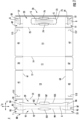
- Fig. 1 is a plan view of the exterior side 1 of a blank, generally indicated at 3, used to form a carton 5 ( Fig. 4 ) according to a first exemplary embodiment of the invention.
- the carton 5 can be used to house a plurality of articles such as containers C.
- the carton 5 has a handle, generally indicated at 7 ( Figs. 4-6 ), formed in a top wall 6 of the carton 5 for grasping and carrying the carton 5.
- the carton 5 is sized to house twenty-four containers in one layer in a 4x6 arrangement, but it is understood that the carton may be sized and shaped to hold containers of a different or same quantity in a single layer, more than one layer, and/or in different row/column arrangements (e.g., 1x6, 3x6, 3x5x2, 2x6, 5x6, 2x6x2, 3x4x2, 2x9, etc.).
- the containers C are cans, but other types of containers (e.g., bottles) can be used in the carton 5 without departing from the invention.
- the blank 3 has a longitudinal axis L1 and a lateral axis L2.
- the blank 3 comprises a bottom panel 11 foldably connected to first and second side panels 13, 15 at respective lateral fold lines 17, 19, a second top panel 23 foldably connected to the first side panel 15 at a lateral fold line 25, and a first top panel 29 foldably connected to the first side panel 13 at a lateral fold line 31.
- the first and second top panels 23, 29 will at least partially overlap in the erected carton 5 to form the top wall 6, as described further herein.
- the bottom panel 11 is foldably connected to a first bottom end flap 35 and a second bottom end flap 37.
- the first side panel 13 is foldably connected to a first side end flap 41 and a second side end flap 43.
- the second side panel 15 is foldably connected to a first side end flap 45 and a second side end flap 47.
- the second top panel 23 is foldably connected to a first top end flap 49 and a second top end flap 51.
- the first top panel 29 is foldably connected to a first top end flap 53 and a second top end flap 55.
- the end flaps 35, 41, 45, 49, 53 extend along a first marginal area of the blank 3, and are foldably connected at a first longitudinal fold line 61.
- the end flaps 37, 43, 47, 51, 55 extend along a second marginal area of the blank 3, and are foldably connected at a second longitudinal fold line 63.
- the longitudinal fold lines 61, 63 may be, for example, substantially straight, offset, or oblique at one or more locations to account for blank thickness or for other factors.
- the blank 3 includes first handle features 70 that comprise a central handle portion 73 that forms a second handle portion in the second top panel 23 defined by a tear line 75 in the second top panel 23.
- the central handle portion 73 may extend between openings 74, 76 in the first top panel 73.
- the tear line 75 may extend along portions of central handle portion 73 that are not bounded by openings 74, 76.
- the blank includes handle features in the end flaps 49, 51 that may each include respective cuts 77, 79 that are generally U-shaped in configuration.
- the cuts 77, 79 could be tear lines such as cuts including nicks without departing from the disclosure.
- one or both of cuts 77, 79 could have a different configuration, for example, a straight cut, an angled cut, or a curved cut.
- Cut 77 of end flap 49 at least partially defines a relief portion 50 that is moveable relative to the remainder of end flap 49
- cut 79 of end flap 51 at least partially defines a relief portion 52 that is movable relative to the remainder of end flap 51, as described further herein.
- the blank 3 includes second handle features 80 that comprises a handle portion 83 forming a first handle portion in the first top panel 29 and that has end portions 85, 87 that extend into respective end flaps 53, 55 such that the handle portion 83 comprises a portion of the first top panel 29 and a portion of the end flaps 53, 55.
- a handle reinforcement flap 91 is foldably connected to the handle portion 83 at respective fold lines 93, 95 and is separable from the handle portion 83 along cut or tear lines 97, 99 extending from an opening 101 along the handle portion 83 in the first top panel 29 to respective fold lines 93, 95.
- cut or tear lines 97, 99 may also be fold lines.
- a portion of fold lines 93, 95 may be obliquely-disposed with respect to respective cut or tear lines 97, 99 such that a widened portions 84, 86 of handle portion 83 are present along respective end flaps 53, 55.
- the handle portion 83 is also defined by cuts or tears 103, 105 extending in opposite directions along axis L2 from an opening 107 in the first top panel 29 and into respective end flaps 53, 55.
- the features of handle 7 further include cuts or tears 111, 113, 115, 117 in respective end flaps 41, 43, 45, 47.
- cuts or tears 111, 113, 115, 117 may have a substantially J-shaped configuration, with a curved portion of the respective cuts or tears 111, 115, and 113, 117 disposed nearest the respective fold lines 61, 63.
- the handle reinforcement flap 91 is folded about fold lines 93, 95 and positioned to be in face-to-face contact and adhered to the handle portion 83.
- the reinforcement flap 91 may be separated from handle portion 83 along cut or tear lines 97, 99 or cut or tear lines 97, 99 may function as fold lines.
- the blank 3 is folded about fold lines 17, 19, 25, 31 so that the second panel 23 overlaps the first top panel 29 to form a generally open-ended sleeve 90 such that an interior 92 of the carton 5 is accessible.
- the top wall is formed by the overlapped top panels 23, 29, and the central handle portion 73 overlaps the handle portion 83 and the reinforcement flap 91 and is adhesively attached thereto, for example, through adhesive G.
- the end flaps 49, 51 overlap the respective end flaps 53, 55 and are adhesively attached thereto, as described further herein, such that the relief portions 50, 52 of the respective end flaps 53, 55 are adhered to the portions 84, 86 of the handle portion 83 in respective end flaps 53, 55.
- Articles such as beverage containers C can be inserted into the open-ended sleeve 90 prior to closing the ends 67, 69. Alternatively, one of the ends 67, 69 can be closed prior to inserting the beverage containers C into the carton 5.
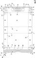
- the assembled carton 5 is illustrated, with overlapped end flaps 49, 53 folded downwardly at fold line 61, overlapped end flaps 51, 55 folded downwardly at fold line 63, and end flaps 35, 37 folded upwardly at respective fold lines 61, 63.
- End flaps 41 and 45 are overlapped over end flaps 49, 53, and 35 to close the first end 67 of the carton 5, and end flaps 43 and 47 are overlapped over end flaps 51, 55, 37 to close the second end 69 of the carton 5.
- the J-shaped cuts 111, 115 may be aligned and positioned to cooperate to form a U-shaped cut in the first closed end 67 that defines a relief portion of the first closed end 67 that is in alignment with and overlaps the relief portion 50 in the end flap 49.
- the cuts 111, 115 in end flaps 41, 45 overlap and align with the cut 77 in the end flap 49 in the closed end 67.
- the J-shaped cuts 113, 117 may be aligned and positioned to cooperate to form a U-shaped cut 127 in the second closed end 69 that defines a relief portion 129 of the second closed end 69 that overlaps and is in alignment with the relief portion 52 in the end flap 51.
- the cuts 113, 117 in the end flaps 43, 47 overlap and align with the cut 79 in the end flap 51 in the closed end 69.
- the closed ends 67, 69 could be otherwise formed and could have other features without departing from the invention.
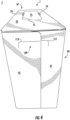
- the assembled handle 7, as shown, is formed by the attachment of the central handle portion 73 of the second top panel 23 to the handle portion 83 and the folded handle reinforcement flap 91 of the first top panel 29.
- the relief portion 50 of the end flap 49 defined by the cut 77 is adhered to the portion 84 of the handle portion 83 along the end flap 49
- the relief portion 52 of the end flap 51 defined by the cut 79 is adhered to the portion 86 of the handle portion 83 along the end flap 51.
- the handle 7 includes a strap handle portion 121 having a three-ply configuration in the overlapped top panels 22, 29 formed by the central handle portion 73, the handle portion 83, and the handle reinforcement flap 91.
- the handle 7 is reinforced by the overlapped portions of the handle features.
- the handle 7 includes portions of the overlapped end flaps 49, 53 forming a three-ply configuration formed by the relief portion 50 of end flap 49 defined by the cut 77 and the portions of handle portion 83 and reinforcing flap 91 along the end flap 53.
- the handle 7 has a four-ply configuration where the relief portion 50 and portions of handle portion 83 and reinforcing flap 91 are overlapped by only one of the side end flaps 41, 45 in the area adjacent respective cuts 111, 115.
- the handle has a five-play configuration in the closed end 67 where the marginal portions of the side end flaps are overlapped.
- the closed end 69 has a four-ply configuration where the end flaps 43, 47 are not overlapped and a five-ply configuration where the end flaps 43, 47 overlap at the relief portion 129 formed in the closed end 69.
- Such reinforced configuration of the handle 7 allows the handle to be used on large cartons 5 such as cartons containing 24 containers without tearing or failure of the handle.
- the handle 7 can have other features or the features shown herein can be otherwise shaped, arranged, configured, and/or omitted without departing from the invention.
- the handle 7 can be activated by grasping the handle portion 121 in the overlapped top panels 23, 29.
- the aligned openings 74, 76, and the opening 107 (aligned with opening 76) provide access along the handle portion 121 for a user to insert a portion of his or her hand at least partially into interior 92 of carton 5 to grasp handle portion 121.
- Lifting of the handle portion 121 may cause tearing and separation of the handle portion 83 from the first top panel 29 and end flaps 53, 55 along tear lines 97, 99, 103, 105 so that the handle portion 121 can be lifted upwardly in an outward direction relative to the remainder of top panels 23, 29 and the interior 92 of the carton 5.
- the handle portion 83 and handle reinforcement flap 91 connect the central handle portion 73 and the overlapped end flaps 49, 53 and 51, 55, respectively, at the ends 67, 69 to increase strength of the handle 7 and distribute lifting forces in the top and ends of the carton 5.
- the three-ply configuration of the handle portion 121 provides enhanced durability that is resistant, for example, to tearing or other weakening such as through contact with fluid.
- the three-ply, four-ply, and five-play configuration of portions of the handle portion 121 provides a substantial grip that can provide better comfort and durability for a user carrying carton 5.
- the relief portion 50 defined by the cut 77 of end flap 49 and the relief portion 52 defined by the cut 79 of end flap 51 provide relief for the handle 7. Because the handle portion 83 is adhered to the relief portions 50, 52 as described above, upward movement of the handle 7 causes the relief portions 50, 52 to flex inwardly toward the interior 92 of the carton 5. Such inward flexion of the portions 50, 52 serves to reduce stresses on both the handle 7 and the ends 67, 69 of the carton 5 to reduce the possibility of tearing.
- such inward flexion of the relief portions 50, 52 serves to provide the handle 7 with an enhanced degree of movement relative to the remainder of carton 5, for example, such that the carton 5 can be jostled or subjected to incidental movement without causing undue stress or strain on either the handle 7 or the hand of a user carrying carton 5.
- the relief portions 125, 129 of the respective ends 67, 69 of the carton 5 formed by respective cuts 111, 115 and 113, 117 are secured to the respective relief portions 50, 52, it will be understood that relief portions 125, 129 may also flex inwardly toward the interior 92 of the carton 5 upon movement of the handle 7 to provide relief as described above.
- the features of the blank 3 that form the handle 7 include a first handle portion 83, a second handle portion 73, a third handle portion comprising the overlapped cuts 77, 111, 115 and relief portion 50 that is overlapped by portions of the side end flaps 41, 45 in the closed end 67 of the carton, and a fourth handle portion comprising the overlapped cuts 79, 113, 117 and relief portion 52 that is overlapped by portions of the side end flaps 43, 47 adjacent the cuts 113, 117 to form the relief portion 129, in the closed end 69 of the carton.
- the second handle portion 73 is spaced apart from the third handle portion and the fourth handle portion and the first handle portion 83 is connected to the second handle portion 73, the third handle portion, and the fourth handle portion to provide strength and reinforcement of the handle 7.
- the blanks according to the present invention can be, for example, formed from coated paperboard and similar materials.
- the interior and/or exterior sides of the blanks can be coated with a clay coating.
- the clay coating may then be printed over with product, advertising, price coding, and other information or images.
- the blanks may then be coated with a varnish to protect any information printed on the blanks.
- the blanks may also be coated with, for example, a moisture barrier layer, on either or both sides of the blanks.
- the blanks may be constructed of paperboard of a caliper such that it is heavier and more rigid than ordinary paper.
- the blanks can also be constructed of other materials, such as cardboard, hard paper, or any other material having properties suitable for enabling the carton package to function at least generally as described above.
- the blanks can also be laminated to or coated with one or more sheet-like materials at selected panels or panel sections.
- glue is intended to encompass all manner of adhesives commonly used to secure carton panels or flaps in place.
- a fold line can be any substantially linear, although not necessarily straight, form of weakening that facilitates folding there along. More specifically, but not for the purpose of narrowing the scope of the present invention, fold lines include: a score line, such as lines formed with a blunt scoring knife, or the like, which creates a crushed portion in the material along the desired line of weakness; a cut that extends partially into a material along the desired line of weakness, and/or a series of cuts that extend partially into and/or completely through the material along the desired line of weakness; and various combinations of these features.
- a score line such as lines formed with a blunt scoring knife, or the like, which creates a crushed portion in the material along the desired line of weakness
- a cut that extends partially into a material along the desired line of weakness, and/or a series of cuts that extend partially into and/or completely through the material along the desired line of weakness; and various combinations of these features.
- a tear line can include: a slit that extends partially into the material along the desired line of weakness, and/or a series of spaced apart slits that extend partially into and/or completely through the material along the desired line of weakness, or various combinations of these features.
- one type tear line is in the form of a series of spaced apart slits that extend completely through the material, with adjacent slits being spaced apart slightly so that a nick (e.g., a small somewhat bridging-like piece of the material) is defined between the adjacent slits for typically temporarily connecting the material across the tear line. The nicks are broken during tearing along the tear line.
- the nicks typically are a relatively small percentage of the tear line, and alternatively the nicks can be omitted from or torn in a tear line such that the tear line is a continuous cut line. That is, it is within the scope of the present invention for each of the tear lines to be replaced with a continuous slit, or the like.
- a cut line can be a continuous slit or could be wider than a slit without departing from the present invention.
Landscapes
- Engineering & Computer Science (AREA)
- Mechanical Engineering (AREA)
- Cartons (AREA)
- Packages (AREA)
Claims (19)
- Karton (5) zur Aufnahme einer Vielzahl von Artikeln (C), wobei der Karton (5) umfasst:eine Vielzahl von Feldern, die sich wenigstens teilweise um einen Innenraum (92) des Kartons (5) erstreckt, wobei die Vielzahl von Feldern ein erstes oberes Feld (29), ein zweites oberes Feld (23), ein unteres Feld (11), ein erstes Seitenfeld (13, 15) und ein zweites Seitenfeld (13, 15) umfasst, wobei das erste obere Feld (29) und das zweite obere Feld (23) sich wenigstens teilweise überlappen, um eine obere Wand (6) des Kartons (5) zu bilden;eine Vielzahl von Endklappen, die faltbar mit einem jeweiligen Feld der Vielzahl von Feldern verbunden sind, um wenigstens teilweise ein geschlossenes Ende (67, 69) des Kartons (5) zu bilden, wobei die Vielzahl von Endklappen eine erste obere Endklappe (53, 55), die faltbar mit dem ersten oberen Feld (29) verbunden ist, eine zweite obere Endklappe (49, 51), die faltbar mit dem zweiten oberen Feld (23) verbunden ist, und wenigstens eine seitliche Endklappe (41, 43, 45, 47), die faltbar mit einem jeweiligen des ersten Seitenfeldes (13, 15) und des zweiten Seitenfeldes (13, 15) verbunden ist, umfasst; undeinen Handgriff (7), der sich wenigstens in der oberen Wand (6) des Kartons (5) erstreckt und der einen ersten Handgriffabschnitt (83) in dem ersten oberen Feld (29), einen zweiten Handgriffabschnitt (73) in dem zweiten oberen Feld (23) und einen dritten Handgriffabschnitt im geschlossenen Ende (67, 69) umfasst, wobei der dritte Handgriffabschnitt wenigstens teilweise durch eine Schwächungslinie (77, 79) in der zweiten oberen Endklappe (49, 51) gebildet ist, wobei die Schwächungslinie (77, 79) eine erste Schwächungslinie (77, 79) ist und wobei der dritte Handgriffabschnitt eine zweite Schwächungslinie (111, 113, 115, 117) in der wenigstens einen seitlichen Endklappe (41, 43, 45, 47) umfasst, wobei sich der erste Handgriffabschnitt (83) in die erste obere Endklappe (53, 55) hinein erstreckt, wobei der erste Handgriffabschnitt (83) mit dem zweiten Handgriffabschnitt (73) und dem dritten Handgriffabschnitt verbunden ist,dadurch gekennzeichnet, dass die erste Schwächungslinie (77, 79) und die zweite Schwächungslinie (111, 113, 115, 117) wenigstens teilweise überlappt sind und dass der zweite Handgriffabschnitt (73) durch eine Aufreißlinie (75) vollständig in dem zweiten oberen Feld definiert ist und dass der zweite Handgriffabschnitt von der wenigstens teilweise überlappten ersten Schwächungslinie und zweiten Schwächungslinie des dritten Handgriffabschnitts beabstandet ist,wobei die Vielzahl von Endklappen eine erste Vielzahl von Endklappen ist und wobei das Ende (67, 69) des Kartons (5) ein erstes Ende (67, 69) des Kartons (5) ist, wobei der Karton (5) eine zweite Vielzahl von Endklappen umfasst, die faltbar mit einem jeweiligen Feld der Vielzahl von Feldern verbunden sind, um ein zweites Ende (67, 69) des Kartons (5) wenigstens teilweise zu verschließen.
- Karton (5) nach Anspruch 1, wobei die wenigstens eine Seitenendklappe (41, 43, 45, 47) eine erste Seitenendklappe (41, 43, 45, 47) ist, die faltbar mit der ersten Seitenwand (13, 15) verbunden ist, wobei die zweite Schwächungslinie (111, 113, 115, 117) in der ersten Seitenendklappe (41, 43, 45, 47) liegt und wobei die Vielzahl von Endklappen eine zweite Seitenendklappe (41, 43, 45, 47) umfasst, die faltbar mit dem zweiten Seitenfeld (13, 15) verbunden ist, wobei der dritte Handgriffabschnitt eine dritte Schwächungslinie (111, 113, 115, 117) in der zweiten Seitenendklappe (41, 43, 45, 47) umfasst, wobei die erste Schwächungslinie (77, 79) und die dritte Schwächungslinie (111, 113, 115, 117) wenigstens teilweise überlappt sind.
- Karton (5) nach Anspruch 1, wobei die erste Schwächungslinie (77, 79) im Allgemeinen U-förmig ist und die zweite Schwächungslinie (111, 113, 115, 117) im Allgemeinen J-förmig ist.
- Karton (5) nach Anspruch 1, der ferner eine Handgriffverstärkungsklappe (91) umfasst, die faltbar mit dem ersten oberen Feld (29) verbunden ist, wobei die Handgriffverstärkungsklappe (91) wenigstens teilweise entlang einer Aufreißlinie (97, 99) von dem ersten oberen Feld (29) trennbar ist, wobei die Aufreißlinie (97, 99) wenigstens einen Abschnitt des ersten Handgriffabschnitts (83) definiert.
- Karton (5) nach Anspruch 1, der ferner eine Handgriffverstärkungsklappe (91) umfasst, die faltbar mit dem ersten oberen Feld (29) verbunden ist, wobei die Handgriffverstärkungsklappe (91) in direktem Kontakt mit dem ersten Handgriffabschnitt (83) steht, wobei ein Abschnitt von wenigstens einem des ersten Handgriffabschnitts (83) und der Handgriffverstärkungsklappe (91) in direktem Kontakt mit dem dritten Handgriffabschnitt steht, wobei ein Abschnitt von wenigstens einem des ersten Handgriffabschnitts (83) und der Handgriffverstärkungsklappe (91) in direktem Kontakt mit dem zweiten Handgriffabschnitt (73) steht.
- Karton (5) nach Anspruch 1, wobei der erste Handgriffabschnitt (83) wenigstens teilweise von dem ersten oberen Feld (29) trennbar ist, wobei der zweite Handgriffabschnitt (73) wenigstens teilweise von dem zweiten oberen Feld (23) trennbar ist und wobei der dritte Handgriffabschnitt wenigstens teilweise von der zweiten oberen Endklappe (49, 51) trennbar ist.
- Karton (5) nach Anspruch 1, wobei die zweite Vielzahl von Endklappen eine dritte obere Endklappe (53, 55), die faltbar mit der ersten oberen Feld (29) verbunden ist, und eine vierte obere Endklappe (49, 51), die faltbar mit der zweiten oberen Feld (23) verbunden ist, umfasst, wobei der Handgriff (7) einen vierten Handgriffabschnitt im zweiten geschlossenen Ende (67, 69) umfasst, wobei der vierte Handgriffabschnitt wenigstens teilweise durch eine Schwächungslinie (77, 79) in der vierten oberen Endklappe (49, 51) geformt ist.
- Karton (5) nach Anspruch 7, wobei der erste Handgriffabschnitt (83) in die dritte obere Endklappe (53, 55) hineinragt, wobei der zweite Handgriffabschnitt (73) vom vierten Handgriffabschnitt beabstandet ist und wobei der erste Handgriffabschnitt (83) mit dem vierten Handgriffabschnitt verbunden ist.
- Karton (5) nach Anspruch 7, wobei die zweite Vielzahl von Endklappen wenigstens eine seitliche Endklappe (41, 43, 45, 47) umfasst, die faltbar mit jeweils einem des ersten Seitenfelds (13, 15) und des zweiten Seitenfelds (13, 15) verbunden ist, wobei der vierte Handgriffabschnitt eine dritte Schwächungslinie (111, 113, 115, 117) in der wenigstens einen seitlichen Endklappe (41, 43, 45, 47) der zweiten Vielzahl von Endklappen umfasst.
- Zuschnitt (3) zum Bilden eines Kartons (5) zum Aufnehmen einer Vielzahl von Artikeln (C) nach einem der Ansprüche 1-9, wobei der Zuschnitt (3) umfasst:eine Vielzahl von Feldern, die ein erstes oberes Feld (29), ein zweites oberes Feld (23), ein unteres Feld (11), ein erstes Seitenfeld (13, 15) und ein zweites Seitenfeld (13, 15) umfasst, wobei das erste obere Feld (29) und das zweite obere Feld (23) dazu dienen, wenigstens teilweise überlappt zu werden, um eine obere Wand (6) des aus dem Zuschnitt geformten Kartons (5) zu bilden,eine Vielzahl von Endklappen, die faltbar mit einem jeweiligen Feld der Vielzahl von Feldern verbunden sind, um wenigstens teilweise ein geschlossenes Ende (67, 69) des aus dem Zuschnitt (3) geformten Kartons (5) zu bilden, wobei die Vielzahl von Endklappen eine erste obere Endklappe (53, 55), die faltbar mit dem ersten oberen Feld (29) verbunden ist, eine zweite obere Endklappe (49, 51), die faltbar mit dem zweiten oberen Feld (23) verbunden ist, und wenigstens eine seitliche Endklappe (41, 43, 45, 47), die faltbar mit einem des jeweiligen ersten Seitenfeldes (13, 15) und des zweiten Seitenfeldes (13, 15) verbunden ist, umfasst; undHandgriffmerkmale zum Bilden eines Handgriffs (7), der sich wenigstens in die obere Wand (6) des Kartons (5) erstreckt, wobei der Handgriff (7) einen ersten Handgriffabschnitt (83) in dem ersten oberen Feld (29), einen zweiten Handgriffabschnitt (73) in dem zweiten oberen Feld (23) und einen dritten Handgriffabschnitt, der wenigstens teilweise durch eine Schwächungslinie (77, 79) in der zweiten oberen Endklappe (49, 51) gebildet ist, umfasst, wobei die Schwächungslinie (77, 79) eine erste Schwächungslinie (77, 79) ist und der dritte Handgriffabschnitt eine zweite Schwächungslinie (111, 113, 115, 117) in der wenigstens einen seitlichen Endklappe (41, 43, 45, 47) umfasst, wobei der erste Handgriffabschnitt (83) sich in die erste obere Endklappe (53, 55) erstreckt, wobei der zweite Handgriffabschnitt (73) von dem dritten Handgriffabschnitt beabstandet ist, wobei der erste Handgriffabschnitt (83) zum Verbinden mit dem zweiten Handgriffabschnitt (73) und dem dritten Handgriffabschnitt in dem aus dem Zuschnitt (3) geformten Karton (5) vorgesehen ist,dadurch gekennzeichnet, dass die erste Schwächungslinie (77, 79) und die zweite Schwächungslinie (111, 113, 115, 117) so ausgebildet sind, dass sie in dem aus dem Zuschnitt (3) geformten Karton (5) wenigstens teilweise überlappt sind, und dass der zweite Handgriffabschnitt (73) durch eine Aufreißlinie (75) vollständig in dem zweiten oberen Feld definiert ist und dass der zweite Handgriffabschnitt von der wenigstens teilweise überlappten ersten Schwächungslinie und zweiten Schwächungslinie des dritten Handgriffabschnitts beabstandet ist,wobei die Vielzahl von Endklappen eine erste Vielzahl von Endklappen ist und das Ende (67, 69) des Kartons (5) ein erstes Ende (67, 69) des Kartons (5) ist, wobei der Karton (5) eine zweite Vielzahl von Endklappen umfasst, die faltbar mit einem jeweiligen Feld der Vielzahl von Feldern verbunden sind, um ein zweites Ende (67, 69) des Kartons (5) wenigstens teilweise zu verschließen.
- Zuschnitt (3) nach Anspruch 10, wobei die wenigstens eine Seitenendklappe (41, 43, 45, 47) eine erste Seitenendklappe (41, 43, 45, 47) ist, die faltbar mit der ersten Seitenwand (13, 15) verbunden ist, wobei sich die zweite Schwächungslinie (111, 113, 115, 117) in der ersten Seitenendklappe (41, 43, 45, 47) befindet und wobei die Vielzahl von Endklappen eine zweite Seitenendklappe (41, 43, 45, 47) umfasst, die faltbar mit der zweiten Seitenwand (13, 15) verbunden ist, wobei der dritte Handgriffabschnitt eine dritte Schwächungslinie (111, 113, 115, 117) in der zweiten Seitenendklappe (41, 43, 45, 47) umfasst, wobei die erste Schwächungslinie (77, 79) und die dritte Schwächungslinie (111, 113, 115, 117) dazu vorgesehen sind, in dem aus dem Zuschnitt (3) geformten Karton (5) wenigstens teilweise überlappt angeordnet zu sein.
- Zuschnitt (3) nach Anspruch 10, wobei die Handgriffmerkmale ferner eine Handgriffverstärkungsklappe (91) umfassen, die faltbar mit dem ersten oberen Feld (29) verbunden ist, wobei die Handgriffverstärkungsklappe (91) an einer Aufreißlinie (97, 99) wenigstens teilweise von dem ersten oberen Feld (29) trennbar ist, wobei die Aufreißlinie (97, 99) wenigstens einen Abschnitt des ersten Handgriffabschnitts (83) definiert, wobei die Handgriffverstärkungsklappe (91) in direktem Kontakt mit dem ersten Handgriffabschnitt (83) steht, wobei ein Abschnitt von wenigstens einem des ersten Handgriffabschnitts (83) und der Handgriffverstärkungsklappe (91) in direktem Kontakt mit dem dritten Handgriffabschnitt steht.
- Zuschnitt (3) nach Anspruch 10, wobei die Handgriffmerkmale ferner eine Handgriffverstärkungsklappe (91) umfassen, die faltbar mit dem ersten oberen Feld (29) verbunden ist, wobei die Handgriffverstärkungsklappe (91) an einer Aufreißlinie (97, 99) wenigstens teilweise von dem ersten oberen Feld (29) trennbar ist, wobei die Aufreißlinie (97, 99) wenigstens einen Abschnitt des ersten Handgriffabschnitts (83) definiert, wobei die Handgriffverstärkungsklappe (91) in direktem Kontakt mit dem ersten Handgriffabschnitt (83) steht, wobei ein Abschnitt des wenigstens einen des ersten Handgriffabschnitts (83) und der Handgriffverstärkungsklappe (91) in direktem Kontakt mit dem zweiten Handgriffabschnitt (73) steht.
- Zuschnitt (3) nach Anspruch 10, wobei der erste Handgriffabschnitt (83) wenigstens teilweise von dem ersten oberen Feld (29) trennbar ist, wobei der zweite Handgriffabschnitt (73) wenigstens teilweise von dem zweiten oberen Feld (23) trennbar ist und wobei der dritte Handgriffabschnitt wenigstens teilweise von der zweiten oberen Endklappe (49, 51) trennbar ist.
- Verfahren zum Bilden eines Kartons (5) zur Aufnahme einer Vielzahl von Artikeln (C) nach einem der Ansprüche 1-9, wobei das Verfahren umfasst:Erhalten eines Zuschnitts (3) mit einer Vielzahl von Feldern, die ein erstes oberes Feld (29), ein zweites oberes Feld (23), ein unteres Feld (11), ein erstes Seitenfeld (13, 15) und ein zweites Seitenfeld (13, 15) umfasst, mit einer Vielzahl von Endklappen, die faltbar mit einem jeweiligen Feld der Vielzahl von Feldern verbunden sind, wobei die Vielzahl von Endklappen eine erste obere Endklappe (53, 55), die faltbar mit dem ersten oberen Feld (29) verbunden ist, eine zweite obere Endklappe (49, 51), die faltbar mit dem zweiten oberen Feld (23) verbunden ist, und wenigstens eine seitliche Endklappe (41, 43, 45, 47), die faltbar mit einem jeweiligen des ersten Seitenfeldes (13, 15) und des zweiten Seitenfeldes (13, 15) verbunden ist, umfasst, und mit Handgriffmerkmalen zum Bilden eines Handgriffs (7), wobei der Handgriff (7) einen ersten Handgriffabschnitt (83) in dem ersten oberen Feld (29), einen zweiten Handgriffabschnitt (73) in dem zweiten oberen Feld (23) und einen dritten Handgriffabschnitt, der wenigstens teilweise durch eine Schwächungslinie (77, 79) in der zweiten oberen Endklappe (49, 51) gebildet ist, umfasst, wobei die Schwächungslinie (77, 79) eine erste Schwächungslinie (77, 79) ist und der dritte Handgriffabschnitt eine zweite Schwächungslinie (111, 113, 115, 117) in der wenigstens einen seitlichen Endklappe (41, 43, 45, 47) umfasst;Falten der Vielzahl von Feldern, um wenigstens teilweise einen Innenraum (92) des Kartons (5) zu bilden, wobei das Falten der Vielzahl von Feldern das wenigstens teilweise Überlappen des ersten oberen Feldes (29) und des zweiten oberen Feldes (23) umfasst, um eine obere Wand (6) zu bilden; undBilden des Handgriffs (7) aus dem ersten Handgriffabschnitt (83), dem zweiten Handgriffabschnitt (73) und dem dritten Handgriffabschnitt, wobei der erste Handgriffabschnitt (83) sich in die erste obere Endklappe (53, 55) hinein erstreckt, wobei der zweite Handgriffabschnitt (73) vom dritten Handgriffabschnitt beabstandet ist und wobei der erste Handgriffabschnitt (83) mit dem zweiten Handgriffabschnitt (73) und dem dritten Handgriffabschnitt verbunden ist,dadurch gekennzeichnet, dass das Bilden des Handgriffs (7) das wenigstens teilweise Überlappen der zweiten oberen Endklappe (49, 51) und der wenigstens einen seitlichen Endklappe (41, 43, 45, 47) umfasst, so dass die erste Schwächungslinie (77, 79) und die zweite Schwächungslinie (111, 113, 115, 117) wenigstens teilweise überlappt sind und so dass der zweite Handgriffabschnitt (73) durch eine Aufreißlinie (75) zur Gänze in dem zweiten oberen Feld definiert ist und so dass der zweite Handgriffabschnitt von der wenigstens teilweise überlappten ersten Schwächungslinie und zweiten Schwächungslinie des dritten Handgriffabschnitts beabstandet ist,wobei die Vielzahl von Endklappen eine erste Vielzahl von Endklappen ist und wobei das Ende (67, 69) des Kartons (5) ein erstes Ende (67, 69) des Kartons (5) ist, wobei der Karton (5) eine zweite Vielzahl von Endklappen umfasst, die faltbar mit einem jeweiligen Feld der Vielzahl von Feldern verbunden sind, um ein zweites Ende (67, 69) des Kartons (5) wenigstens teilweise zu verschließen.
- Verfahren nach Anspruch 15, wobei die wenigstens eine Seitenendklappe (41, 43, 45, 47) eine erste Seitenendklappe (41, 43, 45, 47) ist, die faltbar mit der ersten Seitenwand (13, 15) verbunden ist, die zweite Schwächungslinie (111, 113, 115, 117) sich in der ersten Seitenendklappe (41, 43, 45, 47) befindet, und die Vielzahl von Endklappen eine zweite Seitenendklappe (41, 43, 45, 47) umfasst, die faltbar mit der zweiten Seitenwand (13, 15) verbunden ist, der dritte Handgriffabschnitt eine dritte Schwächungslinie (111, 113, 115, 117) in der zweiten Seitenendklappe (41, 43, 45, 47) umfasst, das Bilden des Handgriffs (7) das wenigstens teilweise Überlappen der zweiten oberen Endklappe (49, 51) und der zweiten Seitenendklappe (41, 43, 45, 47) umfasst, so dass die erste Schwächungslinie (77, 79) und die dritte Schwächungslinie (111, 113, 115, 117) wenigstens teilweise überlappt sind.
- Verfahren nach Anspruch 15, wobei der Zuschnitt (3) ferner eine Handgriffverstärkungsklappe (91) umfasst, die faltbar mit dem ersten oberen Feld (29) verbunden ist und die wenigstens teilweise entlang einer Aufreißlinie (97, 99) von dem ersten oberen Feld (29) trennbar ist, wobei die Aufreißlinie (97, 99) wenigstens einen Abschnitt des ersten Handgriffabschnitts (83) definiert, wobei das Bilden des Handgriffs das Positionieren der Handgriffverstärkungsklappe (91) in direktem Kontakt mit dem ersten Handgriffabschnitt (83) umfasst, wobei ein Abschnitt von wenigstens einem des ersten Handgriffabschnitts (83) und der Handgriffverstärkungsklappe (91) in direktem Kontakt mit dem ersten Handgriffabschnitt ist und wobei ein Abschnitt von dem wenigstens einen des ersten Handgriffabschnitts (83) und der Handgriffverstärkungsklappe (91) in direktem Kontakt mit dem zweiten Handgriffabschnitt (73) ist.
- Verfahren nach Anspruch 15, wobei die zweite Vielzahl von Endklappen eine dritte obere Endklappe (53, 55), die faltbar mit dem ersten oberen Feld (29) verbunden ist, und eine vierte obere Endklappe (49, 51), die faltbar mit dem zweiten oberen Feld (23) verbunden ist, umfasst, wobei der Handgriff einen vierten Handgriffabschnitt im zweiten geschlossenen Ende (67, 69) umfasst, wobei der vierte Handgriffabschnitt wenigstens teilweise durch eine Schwächungslinie (77, 79) in der vierten oberen Endklappe (49, 51) gebildet ist, wobei der erste Handgriffabschnitt (83) sich in die dritte obere Endklappe (53, 55) hinein erstreckt, wobei der zweite Handgriffabschnitt (73) vom vierten Handgriffabschnitt beabstandet ist und wobei der erste Handgriffabschnitt (83) mit dem vierten Handgriffabschnitt verbunden ist.
- Verfahren nach Anspruch 15, wobei die zweite Vielzahl von Endklappen eine dritte obere Endklappe (53, 55), die faltbar mit dem ersten oberen Feld (29) verbunden ist, und eine vierte obere Endklappe (49, 51), die faltbar mit dem zweiten oberen Feld (23) verbunden ist, umfasst, wobei der Handgriff einen vierten Handgriffabschnitt im zweiten geschlossenen Ende (67, 69) umfasst, wobei der vierte Handgriffabschnitt wenigstens teilweise durch eine Schwächungslinie (77, 79) in der vierten oberen Endklappe (49, 51) gebildet ist, wobei die zweite Vielzahl von Endklappen wenigstens eine seitliche Endklappe (41, 43, 45, 47) umfasst, die faltbar mit einem jeweiligen des ersten Seitenfeldes (13, 15) und des zweiten Seitenfeldes (13, 15) verbunden ist, wobei der vierte Handgriffabschnitt eine dritte Schwächungslinie (111, 113, 115, 117) in der wenigstens einen seitlichen Endklappe (41, 43, 45, 47) der zweiten Vielzahl von Endklappen umfasst.
Applications Claiming Priority (2)
| Application Number | Priority Date | Filing Date | Title |
|---|---|---|---|
| US201562256967P | 2015-11-18 | 2015-11-18 | |
| PCT/US2016/062691 WO2017087757A1 (en) | 2015-11-18 | 2016-11-18 | Carton with handle |
Publications (4)
| Publication Number | Publication Date |
|---|---|
| EP3377413A1 EP3377413A1 (de) | 2018-09-26 |
| EP3377413A4 EP3377413A4 (de) | 2019-04-24 |
| EP3377413B1 true EP3377413B1 (de) | 2024-09-04 |
| EP3377413C0 EP3377413C0 (de) | 2024-09-04 |
Family
ID=58691305
Family Applications (1)
| Application Number | Title | Priority Date | Filing Date |
|---|---|---|---|
| EP16867195.6A Active EP3377413B1 (de) | 2015-11-18 | 2016-11-18 | Karton mit griff, zuschnitt und herstellungsverfahren |
Country Status (9)
| Country | Link |
|---|---|
| US (1) | US10421578B2 (de) |
| EP (1) | EP3377413B1 (de) |
| AU (1) | AU2016358086B2 (de) |
| CA (1) | CA3001016C (de) |
| ES (1) | ES2992843T3 (de) |
| MX (1) | MX2018005225A (de) |
| NZ (1) | NZ741201A (de) |
| PL (1) | PL3377413T3 (de) |
| WO (1) | WO2017087757A1 (de) |
Families Citing this family (5)
| Publication number | Priority date | Publication date | Assignee | Title |
|---|---|---|---|---|
| US10214333B2 (en) * | 2014-10-06 | 2019-02-26 | Westrock Packaging Systems, Llc | Carton and carton blank and a handle structure therefor |
| AU2019356899B2 (en) | 2018-10-09 | 2023-02-02 | Graphic Packaging International, Llc | Carton with handle |
| USD1067767S1 (en) * | 2019-04-15 | 2025-03-25 | Mutty Greenfeld | Box |
| WO2021236499A1 (en) * | 2020-05-22 | 2021-11-25 | Graphic Packaging International, Llc | Carton for containers |
| USD966098S1 (en) | 2020-07-14 | 2022-10-11 | Graphic Packaging International, Llc | Carton |
Family Cites Families (74)
| Publication number | Priority date | Publication date | Assignee | Title |
|---|---|---|---|---|
| US1253193A (en) | 1917-04-12 | 1918-01-08 | John W Hill | Paper box. |
| US2681143A (en) | 1950-02-17 | 1954-06-15 | Waldorf Paper Prod Co | Dome top carrier carton |
| US2842304A (en) | 1954-07-07 | 1958-07-08 | Diamond Match Co | Shipping and carrying cartons |
| US2810506A (en) | 1954-11-12 | 1957-10-22 | David E Kessler | One-piece convertible container |
| US2868433A (en) | 1956-05-03 | 1959-01-13 | American Box Board Co | Handle receptacle |
| US2955739A (en) | 1957-08-20 | 1960-10-11 | Container Corp | Handle carton |
| US3076591A (en) | 1961-02-09 | 1963-02-05 | Patent & Licensing Corp | Carton with carrier handle |
| US3112856A (en) | 1962-05-21 | 1963-12-03 | West Virginia Pulp & Paper Co | Handled container |
| US3300119A (en) | 1965-10-04 | 1967-01-24 | Mead Corp | Article carrier |
| US4036423A (en) | 1974-10-23 | 1977-07-19 | International Paper Company | Expandable package |
| US3904036A (en) | 1974-11-15 | 1975-09-09 | Mead Corp | Fully enclosed bottle container |
| US4328923A (en) | 1979-10-22 | 1982-05-11 | Johns-Manville Corporation | Picnic cooler container |
| FR2481231A1 (fr) | 1980-04-25 | 1981-10-30 | Nicollet Hugues Sa | Emballage a poignee, en carton, carton ondule ou autre materiau en feuille, et flan et ebauche propres a la constitution d'un tel emballage |
| US4378905A (en) | 1981-04-10 | 1983-04-05 | Champion International Corporation | Carton with strap handle and blank for forming same |
| EP0084977A3 (de) | 1982-01-27 | 1984-08-01 | The Mead Corporation | Allseitig geschlossener Flaschenbehälter |
| US4470503A (en) | 1983-06-06 | 1984-09-11 | Pack Image, Inc. | Returnable bottle carrier with strap handle |
| US4546914A (en) | 1983-09-16 | 1985-10-15 | Champion International Corporation | Integral three-ply strap handle |
| US4498619A (en) | 1983-10-24 | 1985-02-12 | Champion International Corporation | Carton with carrying handle |
| US4588084A (en) | 1985-05-28 | 1986-05-13 | The Mead Corporation | Enclosed bottle carrier for returnable bottles |
| CA1243987A (en) | 1985-07-29 | 1988-11-01 | William G. Atkinson | Container having improved handle |
| GB2188612B (en) | 1986-04-03 | 1989-12-06 | Mead Corp | Packaging carton having an extensible handle |
| GB8715656D0 (en) | 1987-07-03 | 1987-08-12 | St Regis Packaging Ltd | Carton |
| US5020337A (en) | 1990-01-11 | 1991-06-04 | Krieg David F | Combination ice package and expandable cooler |
| US5328081A (en) | 1992-07-06 | 1994-07-12 | The Mead Corporation | Multi-unit carton with integral handle |
| US5197598A (en) | 1992-07-30 | 1993-03-30 | The Mead Corporation | Enclosed bottle carrier |
| US5240174A (en) | 1992-08-28 | 1993-08-31 | Eveready Battery Company, Inc. | Environmentally friendly and space efficient battery package |
| US5292058A (en) | 1993-04-26 | 1994-03-08 | General Mills, Inc. | Package including an expandable top opening |
| US5297725A (en) | 1993-07-01 | 1994-03-29 | Riverwood International Corporation | Carrier for stacked articles |
| US5333734A (en) | 1993-08-19 | 1994-08-02 | The Mead Corporation | Heavy duty article carrier for cans arranged in a horizontal position |
| US5482203A (en) | 1993-09-03 | 1996-01-09 | The Mead Corporation | Handle reinforcement for a carton |
| US5385234A (en) | 1993-09-03 | 1995-01-31 | The Mead Corporation | Heavy duty article carrier |
| US5495727A (en) | 1994-04-22 | 1996-03-05 | Strong; Bryan | Container and expandable cooler |
| GB9413862D0 (en) | 1994-07-08 | 1994-08-24 | Mead Corp | Beverage carton with strap type carrying handle |
| US5582343A (en) | 1994-10-13 | 1996-12-10 | Dalvey; Jodi A. | Paper-based cooler |
| FR2728868B1 (fr) | 1995-01-02 | 1997-10-17 | Otor Sa | Caisse ou couvercle de caisse de matiere en feuille rigide avec poignee renforcee, flan et procede pour la fabrication d'une telle caisse ou d'un tel couvercle |
| US5595292A (en) | 1995-01-04 | 1997-01-21 | The Mead Corporation | Carton having shock-absorbing carrying handle and package formed therefrom |
| US6019276A (en) | 1995-01-10 | 2000-02-01 | Auclair; Jean-Michel | Carton |
| GB9500428D0 (en) | 1995-01-10 | 1995-03-01 | Mead Corp | Carton |
| GB9504378D0 (en) | 1995-03-04 | 1995-04-26 | Riverwood Int Ltd | Handle arrangement |
| GB9514585D0 (en) | 1995-07-17 | 1995-09-13 | Mead Corp | Beverage carton for bottles with strap type carrying handle |
| GB9516675D0 (en) | 1995-08-15 | 1995-10-18 | Riverwood Int Corp | Handle arrangement for a paperboard carton |
| US5796778A (en) | 1995-09-26 | 1998-08-18 | Symbios, Inc. | Receiver circuit having adaptive equalizer with characteristics determined by signal envelope measurement and method therefor |
| DE29607374U1 (de) | 1996-04-24 | 1996-07-11 | Mann, Wolfgang, Dipl.-Ing., 37281 Wanfried | Geschlossener Faltschachtelkörper mit doppelter Deckelteilauslegung, mit integriertem Einfach-Tragegriff und erhöhter Tragestabilität im Griffbereich, für leichte und mittelschwere Produkte |
| US5639017A (en) | 1996-05-17 | 1997-06-17 | Riverwood International Corporation | Article carrier with integral handle |
| GB9725245D0 (en) | 1997-11-28 | 1998-01-28 | Riverwood Int Corp | Handle arrangement for a carton |
| US20010017314A1 (en) | 1998-08-28 | 2001-08-30 | Eric Boukredine | Beverage carton with strap type carrying handle |
| US5915546A (en) | 1998-04-16 | 1999-06-29 | Riverwood International Corporation | Carton with three-ply handle |
| US5873515A (en) | 1998-06-23 | 1999-02-23 | Riverwood International Corporation | Carton with tear control handle |
| US6129266A (en) | 1999-06-18 | 2000-10-10 | The Mead Corporation | Carton with reinforced handle structure |
| US6065590A (en) * | 1998-10-06 | 2000-05-23 | Riverwood International Corporation | Handled bottle carrier |
| US6425520B1 (en) * | 2000-10-24 | 2002-07-30 | International Paper Company | Beverage carrier |
| JP4695252B2 (ja) | 2000-10-24 | 2011-06-08 | ザ ミード コーポレーション | カートン |
| US6598784B2 (en) | 2000-12-20 | 2003-07-29 | Meadwestvaco Packaging Syatens, Llc | Beverage carton with strap type carrying handle |
| GB0100935D0 (en) | 2001-01-13 | 2001-02-28 | Riverwood Int Corp | A paperboard carton |
| US6631803B2 (en) | 2001-03-21 | 2003-10-14 | Coors Brewing Company | Beverage cooler box |
| DE20112228U1 (de) | 2001-07-06 | 2002-11-14 | A & R Carton Gmbh | Flaschenträger |
| CA2465125C (en) | 2001-10-27 | 2008-08-26 | Meadwestvaco Packaging Systems, Llc | Carton having a strap handle |
| DE202004018649U1 (de) | 2004-11-25 | 2005-04-21 | A&R Carton Gmbh | Behälterträger aus Karton |
| GB2422819A (en) | 2005-02-02 | 2006-08-09 | Meadwestvaco Packaging Systems | Carton having a strap-type carrying handle |
| US20060273143A1 (en) | 2005-06-07 | 2006-12-07 | Bryan Finch | Collapsible container |
| WO2007089282A2 (en) | 2005-09-06 | 2007-08-09 | Meadwestvaco Packaging Systems Llc | Carton with ice retention flaps |
| US20070095882A1 (en) | 2005-10-21 | 2007-05-03 | Holley Jr John M | Carton having strap handle with improved product protection |
| ES2320933T3 (es) | 2005-12-23 | 2009-05-29 | Graphic Packaging International, Inc. | Caja de carton con asa de sujecion. |
| ES2329952T3 (es) * | 2006-02-06 | 2009-12-02 | Graphic Packaging International, Inc. | Caja de carton con asa y distribuidor. |
| CN101437730A (zh) | 2006-04-17 | 2009-05-20 | 米德韦斯特瓦科包装系统有限责任公司 | 具有改善的产品保护性能的吊带提手以及端部手孔的纸箱 |
| DE102006024794A1 (de) | 2006-05-27 | 2007-12-06 | Mahle International Gmbh | Verstellbare Nockenwelle |
| GB0814001D0 (en) | 2008-07-31 | 2008-09-10 | Meadwestvaco Packaging Systems | Hnadle structure for packaging |
| US8191761B2 (en) | 2008-10-30 | 2012-06-05 | Graphic Packaging International, Inc. | Cooler box with handle |
| US8354716B2 (en) * | 2010-07-02 | 2013-01-15 | Macronix International Co., Ltd. | Semiconductor devices and methods of manufacturing the same |
| WO2012009502A2 (en) * | 2010-07-15 | 2012-01-19 | Graphic Packaging International, Inc. | Carton with handle |
| MX336011B (es) | 2011-02-23 | 2016-01-07 | Graphic Packaging Int Inc | Caja de carton con asa y distribuidor. |
| WO2014130788A1 (en) | 2013-02-22 | 2014-08-28 | Graphic Packaging International, Inc. | Carton with handle |
| EP2886127A1 (de) * | 2013-12-18 | 2015-06-24 | Vaxon Biotech | Verfahren zur Emulgierung eines Triepitoppeptids mit Montanid und Kits zu seiner Durchführung |
| US20170008662A1 (en) * | 2015-07-09 | 2017-01-12 | Westrock Packaging Systems, Llc | Carton and carton blank |
-
2016
- 2016-11-18 MX MX2018005225A patent/MX2018005225A/es unknown
- 2016-11-18 AU AU2016358086A patent/AU2016358086B2/en active Active
- 2016-11-18 ES ES16867195T patent/ES2992843T3/es active Active
- 2016-11-18 CA CA3001016A patent/CA3001016C/en active Active
- 2016-11-18 US US15/355,274 patent/US10421578B2/en active Active
- 2016-11-18 PL PL16867195.6T patent/PL3377413T3/pl unknown
- 2016-11-18 NZ NZ74120116A patent/NZ741201A/en active IP Right Revival
- 2016-11-18 EP EP16867195.6A patent/EP3377413B1/de active Active
- 2016-11-18 WO PCT/US2016/062691 patent/WO2017087757A1/en not_active Ceased
Also Published As
| Publication number | Publication date |
|---|---|
| ES2992843T3 (en) | 2024-12-18 |
| NZ741201A (en) | 2019-09-27 |
| US10421578B2 (en) | 2019-09-24 |
| EP3377413C0 (de) | 2024-09-04 |
| CA3001016C (en) | 2020-03-24 |
| EP3377413A1 (de) | 2018-09-26 |
| EP3377413A4 (de) | 2019-04-24 |
| CA3001016A1 (en) | 2017-05-26 |
| MX2018005225A (es) | 2018-08-15 |
| WO2017087757A1 (en) | 2017-05-26 |
| PL3377413T3 (pl) | 2024-12-16 |
| AU2016358086B2 (en) | 2019-04-18 |
| AU2016358086A1 (en) | 2018-04-26 |
| US20170137165A1 (en) | 2017-05-18 |
Similar Documents
| Publication | Publication Date | Title |
|---|---|---|
| EP2874905B1 (de) | Karton mit einsatz | |
| EP2841353B1 (de) | Karton mit einsatz | |
| EP2401209B1 (de) | Schachtel mit griff | |
| EP2593380B1 (de) | Schachtel mit griff | |
| EP2925628B1 (de) | Karton mit griff | |
| EP2326568B1 (de) | Schachtel mit verstärktem griff | |
| EP2588385B1 (de) | Karton mit einsatz | |
| EP2379421B1 (de) | Karton mit verstärkungseinsatz | |
| EP2814757B1 (de) | Karton mit griff | |
| EP2996948B1 (de) | Karton mit artikelschutzfunktionen | |
| EP3212523B1 (de) | Karton für artikel | |
| US10549875B2 (en) | Carton with handle | |
| EP2814756B1 (de) | Schachtel mit verstärktem griff | |
| WO2014025602A1 (en) | Carton with handle | |
| EP3183185B1 (de) | Schachtel mit verstärktem griff | |
| EP3377413B1 (de) | Karton mit griff, zuschnitt und herstellungsverfahren | |
| EP2616358B1 (de) | Schachtel mit griff | |
| US9126716B2 (en) | Carton with handle | |
| EP3119691A1 (de) | Karton für behälter |
Legal Events
| Date | Code | Title | Description |
|---|---|---|---|
| STAA | Information on the status of an ep patent application or granted ep patent |
Free format text: STATUS: THE INTERNATIONAL PUBLICATION HAS BEEN MADE |
|
| PUAI | Public reference made under article 153(3) epc to a published international application that has entered the european phase |
Free format text: ORIGINAL CODE: 0009012 |
|
| STAA | Information on the status of an ep patent application or granted ep patent |
Free format text: STATUS: REQUEST FOR EXAMINATION WAS MADE |
|
| 17P | Request for examination filed |
Effective date: 20180613 |
|
| AK | Designated contracting states |
Kind code of ref document: A1 Designated state(s): AL AT BE BG CH CY CZ DE DK EE ES FI FR GB GR HR HU IE IS IT LI LT LU LV MC MK MT NL NO PL PT RO RS SE SI SK SM TR |
|
| AX | Request for extension of the european patent |
Extension state: BA ME |
|
| DAV | Request for validation of the european patent (deleted) | ||
| DAX | Request for extension of the european patent (deleted) | ||
| A4 | Supplementary search report drawn up and despatched |
Effective date: 20190325 |
|
| RIC1 | Information provided on ipc code assigned before grant |
Ipc: B65D 5/46 20060101AFI20190319BHEP Ipc: B65D 71/48 20060101ALI20190319BHEP Ipc: B65D 5/30 20060101ALI20190319BHEP Ipc: B65D 5/10 20060101ALI20190319BHEP |
|
| STAA | Information on the status of an ep patent application or granted ep patent |
Free format text: STATUS: EXAMINATION IS IN PROGRESS |
|
| 17Q | First examination report despatched |
Effective date: 20200206 |
|
| GRAP | Despatch of communication of intention to grant a patent |
Free format text: ORIGINAL CODE: EPIDOSNIGR1 |
|
| STAA | Information on the status of an ep patent application or granted ep patent |
Free format text: STATUS: GRANT OF PATENT IS INTENDED |
|
| INTG | Intention to grant announced |
Effective date: 20240328 |
|
| GRAS | Grant fee paid |
Free format text: ORIGINAL CODE: EPIDOSNIGR3 |
|
| GRAA | (expected) grant |
Free format text: ORIGINAL CODE: 0009210 |
|
| STAA | Information on the status of an ep patent application or granted ep patent |
Free format text: STATUS: THE PATENT HAS BEEN GRANTED |
|
| AK | Designated contracting states |
Kind code of ref document: B1 Designated state(s): AL AT BE BG CH CY CZ DE DK EE ES FI FR GB GR HR HU IE IS IT LI LT LU LV MC MK MT NL NO PL PT RO RS SE SI SK SM TR |
|
| REG | Reference to a national code |
Ref country code: GB Ref legal event code: FG4D |
|
| REG | Reference to a national code |
Ref country code: CH Ref legal event code: EP |
|
| REG | Reference to a national code |
Ref country code: IE Ref legal event code: FG4D |
|
| REG | Reference to a national code |
Ref country code: DE Ref legal event code: R096 Ref document number: 602016089290 Country of ref document: DE |
|
| U01 | Request for unitary effect filed |
Effective date: 20240904 |
|
| U07 | Unitary effect registered |
Designated state(s): AT BE BG DE DK EE FI FR IT LT LU LV MT NL PT RO SE SI Effective date: 20240923 |
|
| REG | Reference to a national code |
Ref country code: ES Ref legal event code: FG2A Ref document number: 2992843 Country of ref document: ES Kind code of ref document: T3 Effective date: 20241218 |
|
| U20 | Renewal fee for the european patent with unitary effect paid |
Year of fee payment: 9 Effective date: 20241127 |
|
| PG25 | Lapsed in a contracting state [announced via postgrant information from national office to epo] |
Ref country code: NO Free format text: LAPSE BECAUSE OF FAILURE TO SUBMIT A TRANSLATION OF THE DESCRIPTION OR TO PAY THE FEE WITHIN THE PRESCRIBED TIME-LIMIT Effective date: 20241204 |
|
| PG25 | Lapsed in a contracting state [announced via postgrant information from national office to epo] |
Ref country code: GR Free format text: LAPSE BECAUSE OF FAILURE TO SUBMIT A TRANSLATION OF THE DESCRIPTION OR TO PAY THE FEE WITHIN THE PRESCRIBED TIME-LIMIT Effective date: 20241205 |
|
| PG25 | Lapsed in a contracting state [announced via postgrant information from national office to epo] |
Ref country code: HR Free format text: LAPSE BECAUSE OF FAILURE TO SUBMIT A TRANSLATION OF THE DESCRIPTION OR TO PAY THE FEE WITHIN THE PRESCRIBED TIME-LIMIT Effective date: 20240904 |
|
| PG25 | Lapsed in a contracting state [announced via postgrant information from national office to epo] |
Ref country code: RS Free format text: LAPSE BECAUSE OF FAILURE TO SUBMIT A TRANSLATION OF THE DESCRIPTION OR TO PAY THE FEE WITHIN THE PRESCRIBED TIME-LIMIT Effective date: 20241204 |
|
| PG25 | Lapsed in a contracting state [announced via postgrant information from national office to epo] |
Ref country code: RS Free format text: LAPSE BECAUSE OF FAILURE TO SUBMIT A TRANSLATION OF THE DESCRIPTION OR TO PAY THE FEE WITHIN THE PRESCRIBED TIME-LIMIT Effective date: 20241204 Ref country code: NO Free format text: LAPSE BECAUSE OF FAILURE TO SUBMIT A TRANSLATION OF THE DESCRIPTION OR TO PAY THE FEE WITHIN THE PRESCRIBED TIME-LIMIT Effective date: 20241204 Ref country code: HR Free format text: LAPSE BECAUSE OF FAILURE TO SUBMIT A TRANSLATION OF THE DESCRIPTION OR TO PAY THE FEE WITHIN THE PRESCRIBED TIME-LIMIT Effective date: 20240904 Ref country code: GR Free format text: LAPSE BECAUSE OF FAILURE TO SUBMIT A TRANSLATION OF THE DESCRIPTION OR TO PAY THE FEE WITHIN THE PRESCRIBED TIME-LIMIT Effective date: 20241205 |
|
| PG25 | Lapsed in a contracting state [announced via postgrant information from national office to epo] |
Ref country code: IS Free format text: LAPSE BECAUSE OF FAILURE TO SUBMIT A TRANSLATION OF THE DESCRIPTION OR TO PAY THE FEE WITHIN THE PRESCRIBED TIME-LIMIT Effective date: 20250104 |
|
| PG25 | Lapsed in a contracting state [announced via postgrant information from national office to epo] |
Ref country code: SM Free format text: LAPSE BECAUSE OF FAILURE TO SUBMIT A TRANSLATION OF THE DESCRIPTION OR TO PAY THE FEE WITHIN THE PRESCRIBED TIME-LIMIT Effective date: 20240904 |
|
| PG25 | Lapsed in a contracting state [announced via postgrant information from national office to epo] |
Ref country code: CZ Free format text: LAPSE BECAUSE OF FAILURE TO SUBMIT A TRANSLATION OF THE DESCRIPTION OR TO PAY THE FEE WITHIN THE PRESCRIBED TIME-LIMIT Effective date: 20240904 |
|
| PG25 | Lapsed in a contracting state [announced via postgrant information from national office to epo] |
Ref country code: SK Free format text: LAPSE BECAUSE OF FAILURE TO SUBMIT A TRANSLATION OF THE DESCRIPTION OR TO PAY THE FEE WITHIN THE PRESCRIBED TIME-LIMIT Effective date: 20240904 |
|
| REG | Reference to a national code |
Ref country code: CH Ref legal event code: PL |
|
| PG25 | Lapsed in a contracting state [announced via postgrant information from national office to epo] |
Ref country code: MC Free format text: LAPSE BECAUSE OF FAILURE TO SUBMIT A TRANSLATION OF THE DESCRIPTION OR TO PAY THE FEE WITHIN THE PRESCRIBED TIME-LIMIT Effective date: 20240904 |
|
| PLBE | No opposition filed within time limit |
Free format text: ORIGINAL CODE: 0009261 |
|
| STAA | Information on the status of an ep patent application or granted ep patent |
Free format text: STATUS: NO OPPOSITION FILED WITHIN TIME LIMIT |
|
| REG | Reference to a national code |
Ref country code: CH Ref legal event code: PL |
|
| PG25 | Lapsed in a contracting state [announced via postgrant information from national office to epo] |
Ref country code: CH Free format text: LAPSE BECAUSE OF NON-PAYMENT OF DUE FEES Effective date: 20241130 |
|
| 26N | No opposition filed |
Effective date: 20250605 |
|
| PG25 | Lapsed in a contracting state [announced via postgrant information from national office to epo] |
Ref country code: IE Free format text: LAPSE BECAUSE OF NON-PAYMENT OF DUE FEES Effective date: 20241118 |
|
| U20 | Renewal fee for the european patent with unitary effect paid |
Year of fee payment: 10 Effective date: 20251126 |
|
| PGFP | Annual fee paid to national office [announced via postgrant information from national office to epo] |
Ref country code: GB Payment date: 20251127 Year of fee payment: 10 |
|
| PGFP | Annual fee paid to national office [announced via postgrant information from national office to epo] |
Ref country code: PL Payment date: 20251031 Year of fee payment: 10 |
|
| PGFP | Annual fee paid to national office [announced via postgrant information from national office to epo] |
Ref country code: ES Payment date: 20251201 Year of fee payment: 10 |
|
| PG25 | Lapsed in a contracting state [announced via postgrant information from national office to epo] |
Ref country code: HU Free format text: LAPSE BECAUSE OF FAILURE TO SUBMIT A TRANSLATION OF THE DESCRIPTION OR TO PAY THE FEE WITHIN THE PRESCRIBED TIME-LIMIT; INVALID AB INITIO Effective date: 20161118 |
|
| PG25 | Lapsed in a contracting state [announced via postgrant information from national office to epo] |
Ref country code: CY Free format text: LAPSE BECAUSE OF FAILURE TO SUBMIT A TRANSLATION OF THE DESCRIPTION OR TO PAY THE FEE WITHIN THE PRESCRIBED TIME-LIMIT; INVALID AB INITIO Effective date: 20161118 |